EP4203127B1 - Unit cell transfer device - Google Patents
Unit cell transfer device Download PDFInfo
- Publication number
- EP4203127B1 EP4203127B1 EP22760003.8A EP22760003A EP4203127B1 EP 4203127 B1 EP4203127 B1 EP 4203127B1 EP 22760003 A EP22760003 A EP 22760003A EP 4203127 B1 EP4203127 B1 EP 4203127B1
- Authority
- EP
- European Patent Office
- Prior art keywords
- rail
- unit cell
- transfer device
- conveyor
- electrode tab
- Prior art date
- Legal status (The legal status is an assumption and is not a legal conclusion. Google has not performed a legal analysis and makes no representation as to the accuracy of the status listed.)
- Active
Links
Images


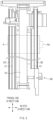


Classifications
-
- H—ELECTRICITY
- H01—ELECTRIC ELEMENTS
- H01M—PROCESSES OR MEANS, e.g. BATTERIES, FOR THE DIRECT CONVERSION OF CHEMICAL ENERGY INTO ELECTRICAL ENERGY
- H01M10/00—Secondary cells; Manufacture thereof
- H01M10/04—Construction or manufacture in general
- H01M10/0404—Machines for assembling batteries
- H01M10/0409—Machines for assembling batteries for cells with wound electrodes
-
- B—PERFORMING OPERATIONS; TRANSPORTING
- B65—CONVEYING; PACKING; STORING; HANDLING THIN OR FILAMENTARY MATERIAL
- B65H—HANDLING THIN OR FILAMENTARY MATERIAL, e.g. SHEETS, WEBS, CABLES
- B65H5/00—Feeding articles separated from piles; Feeding articles to machines
- B65H5/02—Feeding articles separated from piles; Feeding articles to machines by belts or chains, e.g. between belts or chains
- B65H5/021—Feeding articles separated from piles; Feeding articles to machines by belts or chains, e.g. between belts or chains by belts
-
- B—PERFORMING OPERATIONS; TRANSPORTING
- B65—CONVEYING; PACKING; STORING; HANDLING THIN OR FILAMENTARY MATERIAL
- B65H—HANDLING THIN OR FILAMENTARY MATERIAL, e.g. SHEETS, WEBS, CABLES
- B65H5/00—Feeding articles separated from piles; Feeding articles to machines
- B65H5/36—Article guides or smoothers, e.g. movable in operation
- B65H5/38—Article guides or smoothers, e.g. movable in operation immovable in operation
-
- H—ELECTRICITY
- H01—ELECTRIC ELEMENTS
- H01M—PROCESSES OR MEANS, e.g. BATTERIES, FOR THE DIRECT CONVERSION OF CHEMICAL ENERGY INTO ELECTRICAL ENERGY
- H01M10/00—Secondary cells; Manufacture thereof
- H01M10/04—Construction or manufacture in general
-
- H—ELECTRICITY
- H01—ELECTRIC ELEMENTS
- H01M—PROCESSES OR MEANS, e.g. BATTERIES, FOR THE DIRECT CONVERSION OF CHEMICAL ENERGY INTO ELECTRICAL ENERGY
- H01M10/00—Secondary cells; Manufacture thereof
- H01M10/04—Construction or manufacture in general
- H01M10/0404—Machines for assembling batteries
-
- H—ELECTRICITY
- H01—ELECTRIC ELEMENTS
- H01M—PROCESSES OR MEANS, e.g. BATTERIES, FOR THE DIRECT CONVERSION OF CHEMICAL ENERGY INTO ELECTRICAL ENERGY
- H01M10/00—Secondary cells; Manufacture thereof
- H01M10/04—Construction or manufacture in general
- H01M10/0413—Large-sized flat cells or batteries for motive or stationary systems with plate-like electrodes
-
- H—ELECTRICITY
- H01—ELECTRIC ELEMENTS
- H01M—PROCESSES OR MEANS, e.g. BATTERIES, FOR THE DIRECT CONVERSION OF CHEMICAL ENERGY INTO ELECTRICAL ENERGY
- H01M10/00—Secondary cells; Manufacture thereof
- H01M10/04—Construction or manufacture in general
- H01M10/0463—Cells or batteries with horizontal or inclined electrodes
-
- B—PERFORMING OPERATIONS; TRANSPORTING
- B65—CONVEYING; PACKING; STORING; HANDLING THIN OR FILAMENTARY MATERIAL
- B65H—HANDLING THIN OR FILAMENTARY MATERIAL, e.g. SHEETS, WEBS, CABLES
- B65H2701/00—Handled material; Storage means
- B65H2701/10—Handled articles or webs
- B65H2701/19—Specific article or web
-
- B—PERFORMING OPERATIONS; TRANSPORTING
- B65—CONVEYING; PACKING; STORING; HANDLING THIN OR FILAMENTARY MATERIAL
- B65H—HANDLING THIN OR FILAMENTARY MATERIAL, e.g. SHEETS, WEBS, CABLES
- B65H2801/00—Application field
- B65H2801/72—Fuel cell manufacture
-
- Y—GENERAL TAGGING OF NEW TECHNOLOGICAL DEVELOPMENTS; GENERAL TAGGING OF CROSS-SECTIONAL TECHNOLOGIES SPANNING OVER SEVERAL SECTIONS OF THE IPC; TECHNICAL SUBJECTS COVERED BY FORMER USPC CROSS-REFERENCE ART COLLECTIONS [XRACs] AND DIGESTS
- Y02—TECHNOLOGIES OR APPLICATIONS FOR MITIGATION OR ADAPTATION AGAINST CLIMATE CHANGE
- Y02E—REDUCTION OF GREENHOUSE GAS [GHG] EMISSIONS, RELATED TO ENERGY GENERATION, TRANSMISSION OR DISTRIBUTION
- Y02E60/00—Enabling technologies; Technologies with a potential or indirect contribution to GHG emissions mitigation
- Y02E60/10—Energy storage using batteries
-
- Y—GENERAL TAGGING OF NEW TECHNOLOGICAL DEVELOPMENTS; GENERAL TAGGING OF CROSS-SECTIONAL TECHNOLOGIES SPANNING OVER SEVERAL SECTIONS OF THE IPC; TECHNICAL SUBJECTS COVERED BY FORMER USPC CROSS-REFERENCE ART COLLECTIONS [XRACs] AND DIGESTS
- Y02—TECHNOLOGIES OR APPLICATIONS FOR MITIGATION OR ADAPTATION AGAINST CLIMATE CHANGE
- Y02P—CLIMATE CHANGE MITIGATION TECHNOLOGIES IN THE PRODUCTION OR PROCESSING OF GOODS
- Y02P70/00—Climate change mitigation technologies in the production process for final industrial or consumer products
- Y02P70/50—Manufacturing or production processes characterised by the final manufactured product
Definitions
- the present invention relates to a transfer device for a unit cell, which transfers unit cells, in which electrode (negative electrode and positive electrode) and separators are stacked in a predetermined number and order, and more particularly, to a transfer device for a unit cell, in which the unit cell is capable of being minimized in wear and damage due to frictional force generated at a contact portion with a rail during the transferring.
- GB 912 498 A and KR 2019 0092018 A refer to conveyor systems having protrusions on one or more rails.
- the demands for high-efficiency secondary batteries are rapidly increasing in the mobile device and electric vehicle fields.
- a lithium secondary battery having high energy density, maintaining a relatively high voltage, and having a low self-discharge rate is commercially widely used, and research and development for improving performance is actively being conducted.
- the secondary battery has a structure in which an electrode assembly and an electrolyte are embedded in a case such as a can or a pouch.
- the electrode assembly has a structure in which positive electrodes, separators, and negative electrodes are repeatedly stacked.
- the electrode assembly may be classified into a winding type electrode assembly in which positive electrodes, separators, and negative electrodes, which are in the stacked state, are rolled to be embedded in a case and a stack type electrode assembly in which positive electrodes, separators, and negative electrodes, each of which is cut to a predetermined size, are stacked.
- the winding type electrode assembly Since the winding type electrode assembly has a spirally wound structure, the winding type electrode assembly is suitable for being mounted on a cylindrical battery, but is disadvantageous in space utilization for a prismatic or pouch type battery. On the other hand, since the stack type electrode assembly is adjusted in size when the electrode and the separator are cut, the prismatic shape fitted with the case is easily obtained, but a manufacturing process is relatively complicated, and the stack type electrode assembly is relatively vulnerable to an external impact.
- a bicell having a stacked structure of positive electrode/separator/negative electrode, wherein electrodes disposed at the uppermost end and the lowermost end are the same
- a half-cell having a stacked structure of positive electrode/separator/negative electrode, wherein electrodes disposed at the uppermost end and the lowermost end are different from each other
- unit cells each of which has an appropriate size
- the unit cells are transferred one by one from a starting position, at which the unit cells are stored, to a target position, and then, the unit cells are placed on the folding separator so as to be put into a manufacturing device for folding the folding separator.
- the unit cells are transferred through a transfer device.
- FIGS. 1a and 1b that schematically illustrates a transfer device for a unit cell according to the related art
- the unit cell is gripped by a gripper 5 having a clamp structure and then additionally moves by the gripper 5 and is put into a roller 6 provided at an inlet of the manufacturing device.
- the transfer device 1 comprises a conveyor 2, which travels to one side to transfer the seated unit cell 4 when the unit cell 4 is seated, and first and second rails 3a and 3b respectively disposed at one side and the other side of the conveyor 2.
- the conveyor 2 has a structure in which a belt is coupled to wind a plurality of rollers, which are similar to a caterpillar track, at once, and the belt is configured to continuously rotate while the rollers rotate.
- the unit cell 4 moves by the belt.
- a middle portion of the unit cell 4 is seated on the belt, and both sides facing each other with the middle portion therebetween are transferred while being mounted on the first rail 3a and the second rail 3b.
- each of the first rail 3a and the second rail 3b is made of a metal material and has a plate shape
- the unit cell 4 has a problem that friction occurs at the contact portion of the first rail 3a and the second rail 3b during the transferring.
- the friction may wear a surface of the unit cell, and the unit cell may be damaged by the wear.
- the separator is often disposed on the surface of the conveyor, on which the unit cell 4 is seated.
- the separator is manufactured as thin as possible so as to increase in capacity, as a length of the transfer device 1 becomes longer, the wear of the separator occurs by the friction to cause various problems (occurrence of short circuit, deterioration of yield, and the like).
- a main object of the present invention is to provide a transfer device for a unit cell, in which a contact area between rails (first rail and second rail) and a unit cell is minimized to reduce frictional force generated therebetween, thereby solving the problem caused by friction that may occur during transferring of the unit cell.
- the second rail has a length less than that of the first rail and, and when the unit cell is transferred, a tab guide through which the electrode tab protruding from each of the electrodes passes to prevent sagging of the electrode tab is disposed to continue along the traveling direction of the unit cell.
- the protrusion may protrude continuously along a longitudinal direction of the first rail and the second rail.
- At least two or more protrusions may be disposed to be spaced apart from and parallel to each other on each of the first rail and the second rail.
- the first rail and the second rail may be movable away from or close to the conveyor along a width direction perpendicular to the traveling direction of the unit cell.
- Each of the first rail and the second rail may be movable to ascend or descend along a vertical direction.
- a lower arm disposed below the electrode tab and an upper arm disposed above the electrode tab may be disposed in parallel to each other to form a guide groove, into which the electrode tab enters to restrict vertical separation of the electrode tab while the unit cell is transferred, between the upper arm and the lower arm.
- Each of the lower arm and the upper arm may have an inclined surface so that the guide groove increases in size at an end at which the electrode tab starts to enter.
- a height of each of the lower arm and the upper arm which is fixed in a vertical direction, may be adjustable so that a distance and height between the lower arm and the upper arm are adjustable.
- the rail may be made of a synthetic resin to minimize an occurrence of friction.
- the synthetic resin may comprise an acetal resin
- the tab guide may also be made of an acetal resin.
- the wear and damage due to the friction may be maximally suppressed or prevented to reduce the rate of the occurrence of the defects.
- the second rail has the length less than that of the first rail, and when the unit cell is transferred, the tab guide through which the electrode tab passes to prevent the sagging from occurring is disposed along the traveling direction of the unit cell to prevent the sagging of the electrode tab from occurring.
- At least two or more protrusions may be disposed to be spaced apart from each other on each of the first rail and the second rail, thereby distributing the load.
- the first rail and the second rail may be configured to move away from or close to the conveyor along the width direction perpendicular to the traveling direction of the unit cell, and thus, the unit cells having various sizes may be transferred.
- each of the first rail and the second rail is movable to ascend or descend in the vertical direction, the load of the unit cell, which is applied to the protrusion, may be adjusted.
- the tab guide may guide the electrode tab having the various sizes and shapes because the distance and height between the lower arm and the upper arm are adjusted, and each of the lower arm and the upper arm may have the inclined surface to increase in size of the guide groove at the end at which the electrode tab starts to enter so that the electrode tab is smoothly guided between the lower arm and the upper arm without the impact or bending.
- each of the rail and the tab guide may be made of the acetal resin having the low frictional force to minimize the wear of the unit cell.
- the present invention relates to a transfer device for a unit cell, which transfers unit cells, in which negative electrodes, separators, and positive electrodes are stacked by the predetermined number, from a starting position, at which the unit cells are seated, to the predetermined specific target position (e.g., the position at which the gripper stands by).
- the transfer device for the unit cell according to embodiments of the present invention will be described in more detail with reference to the accompanying drawings.
- FIG. 2 is a perspective view of a transfer device for a unit cell according to a preferred embodiment of the present invention
- FIG. 3 is a plan view of the transfer device for the unit cell according to the preferred embodiment of the present invention.
- the transfer device of the present invention comprises a conveyor 10 and first and second rails 20 and 30, which are disposed at one side and the other side of the conveyor 10, respectively.
- the conveyor 10 is configured so that a belt continuously rotates along a longitudinal direction (traveling direction illustrated in FIG. 2 ) by rotation of rollers (not shown), and when the unit cell 4 is seated on the belt, the seated unit cell 4 is transferred. That is, a length of each of the conveyor 10 and the first and second rails 20 and 30 is determined so that the unit cell 4 is transferred to a target point.
- first rail 20 is disposed at one side of the conveyor 10 so as to be parallel to the conveyor 10
- second rail 30 is disposed at the other side of the conveyor 10 with the conveyor 10 therebetween so as to be parallel to the conveyor 10.
- protrusions 21 and 31 protrude from a surface of each of the first rail 20 and the second rail 30 along the traveling direction of the unit cell 4.
- each of the first rail 20 and the second rail 30 has the same or almost similar length as the conveyor 10, and each of the protrusions 21 and 31 protrudes in all sections in which the unit cell 4 travels on each of the first rail 20 and the second rail 30.
- each of the protrusions 21 and 31 protrudes to have a height and size at which a bottom surface of the unit cell 4 is not in contact with a remaining area expect for the protrusions.
- both ends of the unit cell 4 are supported by both the protrusions 21 and 31 and then are transferred. That is, while the unit cell 4 is transferred by the conveyor 10, only the projections 21 and 31 are supported on the first rail 20 and the second rail 30, respectively, and then are transferred.
- the protrusions 21 and 31 protrude continuously along the longitudinal direction of the first rail 20 and the second rail 30 (continuously continuous along the traveling direction), but the protrusions 21 and 31 may be discontinuously formed so as not to be continuous at one or more points.
- the non-continuous section may be determined according to the width of the unit cell.
- each of ends of the protrusions 21 and 31 is formed in a round shape having an appropriate size so that the unit cell 4 is smoothly transferred without scratches.
- At least two or more protrusions 21 and 31 may be disposed to be spaced apart from and parallel to each other on each of the first rail 20 and the second rail 30.
- a gap between the protrusions adjacent to each other is maximally spaced apart from each other along the width direction to distribute a load of the unit cell 4.
- first rail 20 and the second rail 30 may be configured to move away from or close to the conveyor 10 along the width direction perpendicular to the traveling direction of the unit cell 4.
- first rail 20 and the second rail 30 may be adjusted along the width direction according to the size of the unit cell 4.
- each of the first rail 20 and the second rail 30 is movable to ascend or descend in the vertical direction.
- the load applied to the first rail 20 and the second rail 30 may be reduced to minimize an occurrence of frictional force.
- each of the first rail 20 and the second rail 30 may be accomplished by known methods and combinations thereof, such as a combination of a motor and a link device or a combination of a pneumatic device and a gear device.
- the transfer device for a unit cell additionally comprises a tab guide 40 to prevent sagging of an electrode tab 4a from occurring.
- a second rail 30 has a length less than that of the first rail 20, and when the unit cell 4 is transferred, a tab guide 40 through which the electrode tab 4a passes to prevent sagging of the electrode tab 4a from occurring is disposed to continue along a traveling direction of the unit cell 4.
- FIG. 4 is a perspective view of the tab guide 40
- FIG. 5 is a side view of the tab guide 40.
- the tab guide 40 is configured by coupling a lower arm 41 to an upper arm 42, and a guide groove is formed between the lower arm 41 and the upper arm 42 so that the electrode tab 4a enters to be slidable.
- the lower arm 41 is disposed under the electrode tab 4a, which is either a positive electrode tab protruding from a positive electrode provided in the unit cell 4 or a negative electrode tab protruding from a negative electrode provided in the unit cell 4, and the upper arm 42 is spaced apart from the lower arm 41 in parallel to the lower arm 41 to form a guide groove 43 into which the electrode tab 4a enters while the unit cell 4 is transferred.
- the tab guide 40 is disposed only on the second rail 30 as illustrated in FIG. 3 , however if the positive electrode tab and the negative electrode tab are unit cells protruding in directions opposite to each other, in a non-claimed alternative, the tab guide 40 may be installed on the first rail 20 as well as the second rail 30. In such an alternative, each of the first rail 20 and the second rail 30 would be configured to have the same length as a conveyor 10, which comprises a length connected to the tab guide 40.
- the upper arm 42 may be formed shorter along the traveling direction than the lower arm 41 and be configured so that the unit cell 4 does not interfere with the upper arm 42 at a point at which a gripper (not shown) grips the unit cell 4 when the unit cell 4 is picked up.
- a height of each of the lower arm 41 and the upper arm 42 which is fixed in a vertical direction, may be adjusted so that a distance and height between the lower arm 41 and the upper arm 42 are adjustable.
- the lower arm 41 and the upper arm 42 may be configured to increase in area (increase in size of the guide groove) through which the electrode tab 4a is accessible from an end at which the electrode tab 4a starts to enter. Therefore, even if slight bending occurs in the electrode tab 4a, the electrode tab 4a may easily enter the guide groove 43 along inclined surfaces 41a and 42a.
- the rails (the first rail and the second rail) is made of a synthetic resin to minimize generation of frictional force.
- the synthetic resin material is made of an acetal resin
- the tab guide 40 is also made of an acetal resin.
- protrusions 21 and 31 protrude from the first rail 20 and the second rail 30, respectively, and since the unit cell 4 is in contact with only the protrusions 21 and 31 of the first and second rails 20 and 30 during the traveling, wear and damage due to friction may be maximally suppressed or prevented.
- At least two or more protrusions 21 and 31 may be disposed to be spaced apart from each other on each of the first rail and the second rail, thereby distributing the load.
- the first rail 20 and the second rail 30 may be configured to move away from or close to the conveyor 10 along a width direction perpendicular to the traveling direction of the unit cell 4, thereby transferring unit cells having various sizes.
- each of the first rail 20 and the second rail 30 is movable to ascend or descend in the vertical direction, the load of the unit cell, which is applied to the protrusions 21 and 31, may be adjusted.
- the second rail 30 has a length less than that of the first rail 20, and when the unit cell 4 is transferred, a tab guide 40 through which the electrode tab 4a passes to prevent sagging of the electrode tab 4a from occurring is disposed to continue along a traveling direction of the unit cell 4, thereby preventing the electrode tab from sagging.
- the tab guide 40 may guide the electrode tabs 4a having various sizes and shapes because a distance and height between the lower arm 41 and the upper arm 42 are adjusted, and the lower arm 41 and the upper arm 42 may have inclined surfaces 41a and 42a to increase in size of the guide groove 43 at the end at which the electrode tab 4a starts to enter so that the electrode tab 4a is guided between the lower arm 31 and the upper arm 42 without an impact.
- each of the rail (the first rail and the second rail) and the tab guide may be made of the acetal resin having the low frictional force to minimize the wear of the unit cell.
Landscapes
- Engineering & Computer Science (AREA)
- Manufacturing & Machinery (AREA)
- Chemical & Material Sciences (AREA)
- Chemical Kinetics & Catalysis (AREA)
- Electrochemistry (AREA)
- General Chemical & Material Sciences (AREA)
- Mechanical Engineering (AREA)
- Secondary Cells (AREA)
- Intermediate Stations On Conveyors (AREA)
- Apparatus Associated With Microorganisms And Enzymes (AREA)
Description
- The present application claims the benefit of the priority of
Korean Patent Application No. 10-2021-0024397, filed on February 23, 2021 - The present invention relates to a transfer device for a unit cell, which transfers unit cells, in which electrode (negative electrode and positive electrode) and separators are stacked in a predetermined number and order, and more particularly, to a transfer device for a unit cell, in which the unit cell is capable of being minimized in wear and damage due to frictional force generated at a contact portion with a rail during the transferring.
- The prior art pertinent to the present invention is given particularly by
GB 912 498 A KR 2019 0092018 A
The demands for high-efficiency secondary batteries are rapidly increasing in the mobile device and electric vehicle fields. Among such the secondary batteries, a lithium secondary battery having high energy density, maintaining a relatively high voltage, and having a low self-discharge rate is commercially widely used, and research and development for improving performance is actively being conducted. - The secondary battery has a structure in which an electrode assembly and an electrolyte are embedded in a case such as a can or a pouch. The electrode assembly has a structure in which positive electrodes, separators, and negative electrodes are repeatedly stacked. In general, the electrode assembly may be classified into a winding type electrode assembly in which positive electrodes, separators, and negative electrodes, which are in the stacked state, are rolled to be embedded in a case and a stack type electrode assembly in which positive electrodes, separators, and negative electrodes, each of which is cut to a predetermined size, are stacked.
- Since the winding type electrode assembly has a spirally wound structure, the winding type electrode assembly is suitable for being mounted on a cylindrical battery, but is disadvantageous in space utilization for a prismatic or pouch type battery. On the other hand, since the stack type electrode assembly is adjusted in size when the electrode and the separator are cut, the prismatic shape fitted with the case is easily obtained, but a manufacturing process is relatively complicated, and the stack type electrode assembly is relatively vulnerable to an external impact.
- In addition, after a bicell (having a stacked structure of positive electrode/separator/negative electrode, wherein electrodes disposed at the uppermost end and the lowermost end are the same) and/or a half-cell (having a stacked structure of positive electrode/separator/negative electrode, wherein electrodes disposed at the uppermost end and the lowermost end are different from each other) are manufactured into unit cells, each of which has an appropriate size, so that advantages of the winding type electrode assembly and advantages of the stack type electrode assembly are combined with each other, a stack & folding process of manufacturing an electrode assembly by folding a folding separator after the unit cells are arranged at intervals on the folding separator has been developed.
- In the stack & folding process, after pre-manufacturing a unit cell having a pre-planned structure, the unit cells are transferred one by one from a starting position, at which the unit cells are stored, to a target position, and then, the unit cells are placed on the folding separator so as to be put into a manufacturing device for folding the folding separator.
- Here, the unit cells are transferred through a transfer device. Referring to
FIGS. 1a and1b that schematically illustrates a transfer device for a unit cell according to the related art, when aunit cell 4 seated on atransfer device 1 is transferred up to a target position, the unit cell is gripped by agripper 5 having a clamp structure and then additionally moves by thegripper 5 and is put into a roller 6 provided at an inlet of the manufacturing device. - Here, the
transfer device 1 comprises aconveyor 2, which travels to one side to transfer theseated unit cell 4 when theunit cell 4 is seated, and first andsecond rails conveyor 2. - The
conveyor 2 has a structure in which a belt is coupled to wind a plurality of rollers, which are similar to a caterpillar track, at once, and the belt is configured to continuously rotate while the rollers rotate. Thus, when theunit cell 4 is seated on the belt, theunit cell 4 moves by the belt. Here, a middle portion of theunit cell 4 is seated on the belt, and both sides facing each other with the middle portion therebetween are transferred while being mounted on thefirst rail 3a and thesecond rail 3b. - In the structure according to the related art, since each of the
first rail 3a and thesecond rail 3b is made of a metal material and has a plate shape, theunit cell 4 has a problem that friction occurs at the contact portion of thefirst rail 3a and thesecond rail 3b during the transferring. The friction may wear a surface of the unit cell, and the unit cell may be damaged by the wear. - Particularly, in the
unit cell 4, the separator is often disposed on the surface of the conveyor, on which theunit cell 4 is seated. Thus, when the separator is manufactured as thin as possible so as to increase in capacity, as a length of thetransfer device 1 becomes longer, the wear of the separator occurs by the friction to cause various problems (occurrence of short circuit, deterioration of yield, and the like). - Accordingly, a main object of the present invention is to provide a transfer device for a unit cell, in which a contact area between rails (first rail and second rail) and a unit cell is minimized to reduce frictional force generated therebetween, thereby solving the problem caused by friction that may occur during transferring of the unit cell.
- The second rail has a length less than that of the first rail and, and when the unit cell is transferred, a tab guide through which the electrode tab protruding from each of the electrodes passes to prevent sagging of the electrode tab is disposed to continue along the traveling direction of the unit cell.
- The present invention is defined by the subject matter of the appending
claim 1. Particular examples are given by the features of the dependent claims. - According to a preferred embodiment, the protrusion may protrude continuously along a longitudinal direction of the first rail and the second rail.
- At least two or more protrusions may be disposed to be spaced apart from and parallel to each other on each of the first rail and the second rail.
- The first rail and the second rail may be movable away from or close to the conveyor along a width direction perpendicular to the traveling direction of the unit cell.
- Each of the first rail and the second rail may be movable to ascend or descend along a vertical direction.
- In the tab guide, a lower arm disposed below the electrode tab and an upper arm disposed above the electrode tab may be disposed in parallel to each other to form a guide groove, into which the electrode tab enters to restrict vertical separation of the electrode tab while the unit cell is transferred, between the upper arm and the lower arm.
- Each of the lower arm and the upper arm may have an inclined surface so that the guide groove increases in size at an end at which the electrode tab starts to enter.
- A height of each of the lower arm and the upper arm, which is fixed in a vertical direction, may be adjustable so that a distance and height between the lower arm and the upper arm are adjustable.
- In addition, it is preferable that the rail may be made of a synthetic resin to minimize an occurrence of friction. Particularly, it is preferable that the synthetic resin may comprise an acetal resin, and also, the tab guide may also be made of an acetal resin.
- According to the present invention having the above configuration, since the protrusion protrudes from each of the first rail and the second rail, and the unit cell is in contact with only the protrusion of each of the first rail and the second rail during the traveling, the wear and damage due to the friction may be maximally suppressed or prevented to reduce the rate of the occurrence of the defects.
- The second rail has the length less than that of the first rail, and when the unit cell is transferred, the tab guide through which the electrode tab passes to prevent the sagging from occurring is disposed along the traveling direction of the unit cell to prevent the sagging of the electrode tab from occurring.
- At least two or more protrusions may be disposed to be spaced apart from each other on each of the first rail and the second rail, thereby distributing the load.
- The first rail and the second rail may be configured to move away from or close to the conveyor along the width direction perpendicular to the traveling direction of the unit cell, and thus, the unit cells having various sizes may be transferred.
- Since each of the first rail and the second rail is movable to ascend or descend in the vertical direction, the load of the unit cell, which is applied to the protrusion, may be adjusted.
- The tab guide may guide the electrode tab having the various sizes and shapes because the distance and height between the lower arm and the upper arm are adjusted, and each of the lower arm and the upper arm may have the inclined surface to increase in size of the guide groove at the end at which the electrode tab starts to enter so that the electrode tab is smoothly guided between the lower arm and the upper arm without the impact or bending.
- In addition, in the present invention, each of the rail and the tab guide may be made of the acetal resin having the low frictional force to minimize the wear of the unit cell.
-
-
FIG. 1a is a schematic side view of a transfer device for a unit cell according to a related art. -
FIG. 1b is a schematic plan view of the transfer device for the unit cell according to the related art. -
FIG. 2 is a perspective view of a transfer device for a unit cell according to a preferred embodiment of the present invention. -
FIG. 3 is a plan view of the transfer device for the unit cell according to the preferred embodiment of the present invention. -
FIG. 4 is a perspective view of a tab guide. -
FIG. 5 is a side view of the tab guide. - Hereinafter, preferred embodiments of the present invention will be described in detail with reference to the accompanying drawings in such a manner that the technical idea of the present invention may easily be carried out by a person with ordinary skill in the art to which the invention pertains. The present invention may, however, be embodied in different forms and should not be construed as limited to the embodiments set forth herein.
- In order to clearly describe the present invention, parts irrelevant to the description are omitted, and the same reference numerals are assigned to the same or similar components throughout the specification.
- Also, terms or words used in this specification and claims should not be restrictively interpreted as ordinary meanings or dictionary-based meanings, but should be interpreted as meanings and concepts conforming to the scope of the present invention on the basis of the principle that an inventor can properly define the concept of a term to describe and explain his or her invention in the best ways.
- The present invention relates to a transfer device for a unit cell, which transfers unit cells, in which negative electrodes, separators, and positive electrodes are stacked by the predetermined number, from a starting position, at which the unit cells are seated, to the predetermined specific target position (e.g., the position at which the gripper stands by). Hereinafter, the transfer device for the unit cell according to embodiments of the present invention will be described in more detail with reference to the accompanying drawings.
-
FIG. 2 is a perspective view of a transfer device for a unit cell according to a preferred embodiment of the present invention, andFIG. 3 is a plan view of the transfer device for the unit cell according to the preferred embodiment of the present invention. - Referring to
FIGS. 2 and3 , the transfer device of the present invention comprises aconveyor 10 and first andsecond rails conveyor 10, respectively. - The
conveyor 10 is configured so that a belt continuously rotates along a longitudinal direction (traveling direction illustrated inFIG. 2 ) by rotation of rollers (not shown), and when theunit cell 4 is seated on the belt, the seatedunit cell 4 is transferred. That is, a length of each of theconveyor 10 and the first andsecond rails unit cell 4 is transferred to a target point. - In addition, the
first rail 20 is disposed at one side of theconveyor 10 so as to be parallel to theconveyor 10, and thesecond rail 30 is disposed at the other side of theconveyor 10 with theconveyor 10 therebetween so as to be parallel to theconveyor 10. - In addition, in the present invention,
protrusions first rail 20 and thesecond rail 30 along the traveling direction of theunit cell 4. Here, each of thefirst rail 20 and thesecond rail 30 has the same or almost similar length as theconveyor 10, and each of theprotrusions unit cell 4 travels on each of thefirst rail 20 and thesecond rail 30. - When the
unit cell 4 is seated on each of theprotrusions protrusions unit cell 4 is not in contact with a remaining area expect for the protrusions. - Thus, while the
unit cell 4 is transferred through theconveyor 10, both ends of theunit cell 4 are supported by both theprotrusions unit cell 4 is transferred by theconveyor 10, only theprojections first rail 20 and thesecond rail 30, respectively, and then are transferred. - It is preferable that the
protrusions first rail 20 and the second rail 30 (continuously continuous along the traveling direction), but theprotrusions protrusions unit cell 4 is smoothly transferred without scratches. - In addition, at least two or
more protrusions first rail 20 and thesecond rail 30. In each of thefirst rail 20 and thesecond rail 30, it is preferable that a gap between the protrusions adjacent to each other is maximally spaced apart from each other along the width direction to distribute a load of theunit cell 4. - Furthermore, the
first rail 20 and thesecond rail 30 may be configured to move away from or close to theconveyor 10 along the width direction perpendicular to the traveling direction of theunit cell 4. Thus, when theunit cell 4 is seated as illustrated inFIG. 3 , thefirst rail 20 and thesecond rail 30 may be adjusted along the width direction according to the size of theunit cell 4. - In addition, each of the
first rail 20 and thesecond rail 30 is movable to ascend or descend in the vertical direction. Thus, since the distribution of the load of theunit cell 4, which is applied to theconveyor 10 and the first andsecond rails first rail 20 and thesecond rail 30 may be reduced to minimize an occurrence of frictional force. - For reference, movement of each of the
first rail 20 and thesecond rail 30 may be accomplished by known methods and combinations thereof, such as a combination of a motor and a link device or a combination of a pneumatic device and a gear device. - The transfer device for a unit cell, additionally comprises a
tab guide 40 to prevent sagging of anelectrode tab 4a from occurring. - As illustrated in
FIG. 3 , asecond rail 30 has a length less than that of thefirst rail 20, and when theunit cell 4 is transferred, atab guide 40 through which theelectrode tab 4a passes to prevent sagging of theelectrode tab 4a from occurring is disposed to continue along a traveling direction of theunit cell 4. -
FIG. 4 is a perspective view of thetab guide 40, andFIG. 5 is a side view of thetab guide 40. As illustrated inFIGS. 4 and5 , thetab guide 40 is configured by coupling alower arm 41 to anupper arm 42, and a guide groove is formed between thelower arm 41 and theupper arm 42 so that theelectrode tab 4a enters to be slidable. - That is, the
lower arm 41 is disposed under theelectrode tab 4a, which is either a positive electrode tab protruding from a positive electrode provided in theunit cell 4 or a negative electrode tab protruding from a negative electrode provided in theunit cell 4, and theupper arm 42 is spaced apart from thelower arm 41 in parallel to thelower arm 41 to form aguide groove 43 into which theelectrode tab 4a enters while theunit cell 4 is transferred. According to the present invention, thetab guide 40 is disposed only on thesecond rail 30 as illustrated inFIG. 3 , however if the positive electrode tab and the negative electrode tab are unit cells protruding in directions opposite to each other, in a non-claimed alternative, thetab guide 40 may be installed on thefirst rail 20 as well as thesecond rail 30. In such an alternative, each of thefirst rail 20 and thesecond rail 30 would be configured to have the same length as aconveyor 10, which comprises a length connected to thetab guide 40. - In addition, as illustrated in
FIG. 4 , theupper arm 42 may be formed shorter along the traveling direction than thelower arm 41 and be configured so that theunit cell 4 does not interfere with theupper arm 42 at a point at which a gripper (not shown) grips theunit cell 4 when theunit cell 4 is picked up. - In addition, a height of each of the
lower arm 41 and theupper arm 42, which is fixed in a vertical direction, may be adjusted so that a distance and height between thelower arm 41 and theupper arm 42 are adjustable. - In addition, as illustrated more clearly in
FIG. 5 , thelower arm 41 and theupper arm 42 may be configured to increase in area (increase in size of the guide groove) through which theelectrode tab 4a is accessible from an end at which theelectrode tab 4a starts to enter. Therefore, even if slight bending occurs in theelectrode tab 4a, theelectrode tab 4a may easily enter theguide groove 43 alonginclined surfaces - In the present invention, it is preferable that the rails (the first rail and the second rail) is made of a synthetic resin to minimize generation of frictional force. Particularly, it is preferable that the synthetic resin material is made of an acetal resin, and also, the
tab guide 40 is also made of an acetal resin. - In the present invention having the above configuration,
protrusions first rail 20 and thesecond rail 30, respectively, and since theunit cell 4 is in contact with only theprotrusions second rails - At least two or
more protrusions - The
first rail 20 and thesecond rail 30 may be configured to move away from or close to theconveyor 10 along a width direction perpendicular to the traveling direction of theunit cell 4, thereby transferring unit cells having various sizes. - Since each of the
first rail 20 and thesecond rail 30 is movable to ascend or descend in the vertical direction, the load of the unit cell, which is applied to theprotrusions - The
second rail 30 has a length less than that of thefirst rail 20, and when theunit cell 4 is transferred, atab guide 40 through which theelectrode tab 4a passes to prevent sagging of theelectrode tab 4a from occurring is disposed to continue along a traveling direction of theunit cell 4, thereby preventing the electrode tab from sagging. - The
tab guide 40 may guide theelectrode tabs 4a having various sizes and shapes because a distance and height between thelower arm 41 and theupper arm 42 are adjusted, and thelower arm 41 and theupper arm 42 may haveinclined surfaces guide groove 43 at the end at which theelectrode tab 4a starts to enter so that theelectrode tab 4a is guided between thelower arm 31 and theupper arm 42 without an impact. - In addition, in the present invention, each of the rail (the first rail and the second rail) and the tab guide may be made of the acetal resin having the low frictional force to minimize the wear of the unit cell.
-
- 4: Unit cell
- 4a: Electrode tab
- 10: Conveyor
- 20: First rail
- 21, 31: Protrusion
- 30: Second rail
- 40: Tab guide
Claims (11)
- A transfer device for a unit cell (4) , in which electrodes and separators are stacked by a predetermined number, the transfer device comprising:a conveyor (10) configured to travel in one direction and transfer the seated unit cell (4) when the unit cell (4) is seated;a first rail (20) disposed at one side of the conveyor (10) in parallel to the conveyor (10); anda second rail (30) disposed at the other side of the conveyor (10) in parallel to the conveyor (10),wherein a protrusion (21, 31) protrudes from a surface of each of the first rail (20) and the second rail (30) along the traveling direction of the unit cell (4), and the unit cell (4) is supported by the protrusion (21, 31) and transferred while being transferred through the conveyor (10),wherein the second rail (30) has a length less than that of the first rail (30), and is continued along the traveling direction of the unit cell (4) by a tab guide (40), through which the electrode tab (4a) protruding from each of the electrodes passes when the unit cell (4) is transferred, in order to prevent sagging of the electrode tab (4a).
- The transfer device of claim 1, wherein the protrusion (21, 31) protrudes continuously along a longitudinal direction of the first rail (20) and the second rail (30).
- The transfer device of claim 2, wherein at least two or more protrusions (21, 31) are disposed to be spaced apart from and parallel to each other on each of the first rail (20) and the second rail (30).
- The transfer device of claim 1, wherein the first rail (20) and the second rail (30) are movable away from or close to the conveyor (10) along a width direction perpendicular to the traveling direction of the unit cell (4).
- The transfer device of claim 1, wherein each of the first rail (20) and the second rail (30) is movable to ascend or descend along a vertical direction.
- The transfer device of claim 1, wherein, in the tab guide (40), a lower arm (41) disposed to be below the electrode tab (4a) and an upper arm (42) disposed to be above the electrode tab (4a) are disposed in parallel to each other to form a guide groove (43), into which the electrode tab (4a) enters to restrict vertical separation of the electrode tab (4a) while the unit cell (4) is transferred, between the upper arm (42) and the lower arm (41).
- The transfer device of claim 6, wherein each of the lower arm (41) and the upper arm (42) has an inclined surface (41a, 42a) so that the guide groove (43) increases in size at an end at which the electrode tab (4a) starts to enter.
- The transfer device of claim 6, wherein a height of each of the lower arm (41) and the upper arm (42), which is fixed in a vertical direction, is adjustable so that a distance and height between the lower arm (41) and the upper arm (42) are adjustable.
- The transfer device of any one of claims 1 to 8, wherein the rail (20, 30) is made of a synthetic resin.
- The transfer device of claim 9, wherein the synthetic resin comprises an acetal resin.
- The transfer device of any one of the preceding claims, wherein the tab guide (40) is made of an acetal resin.
Applications Claiming Priority (2)
| Application Number | Priority Date | Filing Date | Title |
|---|---|---|---|
| KR1020210024397A KR102852651B1 (en) | 2021-02-23 | 2021-02-23 | Transport apparatus for unit cell |
| PCT/KR2022/002535 WO2022182085A1 (en) | 2021-02-23 | 2022-02-21 | Unit cell transfer device |
Publications (3)
| Publication Number | Publication Date |
|---|---|
| EP4203127A1 EP4203127A1 (en) | 2023-06-28 |
| EP4203127A4 EP4203127A4 (en) | 2024-04-03 |
| EP4203127B1 true EP4203127B1 (en) | 2025-05-28 |
Family
ID=83049463
Family Applications (1)
| Application Number | Title | Priority Date | Filing Date |
|---|---|---|---|
| EP22760003.8A Active EP4203127B1 (en) | 2021-02-23 | 2022-02-21 | Unit cell transfer device |
Country Status (7)
| Country | Link |
|---|---|
| US (1) | US20230307689A1 (en) |
| EP (1) | EP4203127B1 (en) |
| KR (1) | KR102852651B1 (en) |
| CN (1) | CN116264833B (en) |
| ES (1) | ES3038274T3 (en) |
| HU (1) | HUE072229T2 (en) |
| WO (1) | WO2022182085A1 (en) |
Family Cites Families (18)
| Publication number | Priority date | Publication date | Assignee | Title |
|---|---|---|---|---|
| GB912498A (en) * | 1959-03-11 | 1962-12-12 | Rapids Standard Co Inc | Conveyor |
| JPH09286551A (en) * | 1996-04-22 | 1997-11-04 | Shin Kobe Electric Mach Co Ltd | Method and device for adsorbing, conveying and accumulating electrode plates |
| KR20100113780A (en) * | 2009-04-14 | 2010-10-22 | 삼성테크윈 주식회사 | Conveyor system capable of rail width and stopper position control |
| KR101241928B1 (en) | 2010-12-13 | 2013-03-11 | (주)열린기술 | Apparatus for manufacturing pocketed electrode plate |
| KR101738724B1 (en) | 2013-12-03 | 2017-05-22 | 주식회사 엘지화학 | Unit cell supplying system |
| JP6569297B2 (en) | 2015-05-22 | 2019-09-04 | 株式会社豊田自動織機 | Conveying device for manufacturing electrode plate and method for manufacturing electrode plate |
| KR101940149B1 (en) * | 2015-07-03 | 2019-01-18 | 주식회사 엘지화학 | Secondary battery and manufacturing method of thereof |
| KR102002315B1 (en) * | 2015-08-17 | 2019-10-01 | 주식회사 엘지화학 | Electrode Assembly of Irregular Structure Comprising Unit Cells with Different Capacity and Size and Battery Cell Having the Same |
| KR102018849B1 (en) * | 2015-11-11 | 2019-09-05 | 주식회사 엘지화학 | Battery Cell Comprising Electrode Lead Having Protruding Extension Part and Tab Connection Part |
| CN109789973B (en) * | 2016-09-26 | 2021-06-25 | 阿自倍尔株式会社 | Conveyor |
| JP2018114571A (en) * | 2017-01-17 | 2018-07-26 | 日特エンジニアリング株式会社 | Pallet transport device and method for transporting pallet |
| KR102521066B1 (en) * | 2018-01-30 | 2023-04-13 | 주식회사 엘지에너지솔루션 | Transport method and apparatus for unit cell |
| KR102439126B1 (en) * | 2018-01-30 | 2022-09-02 | 주식회사 엘지에너지솔루션 | Unit cell transfer method and transfer device |
| JP6879282B2 (en) * | 2018-11-06 | 2021-06-02 | トヨタ自動車株式会社 | Laminated body manufacturing equipment for sheet-shaped electrodes |
| JP6879283B2 (en) * | 2018-11-13 | 2021-06-02 | トヨタ自動車株式会社 | Laminated body manufacturing equipment for sheet-shaped electrodes |
| KR102602209B1 (en) * | 2018-11-21 | 2023-11-14 | (주)이티에스 | Apparatus for forming a pouch of secondary cell |
| JP6888645B2 (en) * | 2019-05-08 | 2021-06-16 | トヨタ自動車株式会社 | Transfer device and transfer method |
| KR20210024397A (en) | 2019-08-25 | 2021-03-05 | 석봉수 | Batter including chicken breast powder and its manufacturing method |
-
2021
- 2021-02-23 KR KR1020210024397A patent/KR102852651B1/en active Active
-
2022
- 2022-02-21 ES ES22760003T patent/ES3038274T3/en active Active
- 2022-02-21 WO PCT/KR2022/002535 patent/WO2022182085A1/en not_active Ceased
- 2022-02-21 CN CN202280006691.9A patent/CN116264833B/en active Active
- 2022-02-21 EP EP22760003.8A patent/EP4203127B1/en active Active
- 2022-02-21 HU HUE22760003A patent/HUE072229T2/en unknown
- 2022-02-21 US US18/031,792 patent/US20230307689A1/en active Pending
Also Published As
| Publication number | Publication date |
|---|---|
| ES3038274T3 (en) | 2025-10-10 |
| US20230307689A1 (en) | 2023-09-28 |
| WO2022182085A1 (en) | 2022-09-01 |
| EP4203127A4 (en) | 2024-04-03 |
| CN116264833B (en) | 2026-03-17 |
| CN116264833A (en) | 2023-06-16 |
| KR20220120373A (en) | 2022-08-30 |
| HUE072229T2 (en) | 2025-11-28 |
| EP4203127A1 (en) | 2023-06-28 |
| KR102852651B1 (en) | 2025-08-29 |
Similar Documents
| Publication | Publication Date | Title |
|---|---|---|
| KR101291063B1 (en) | Stacking system and method for Secondary Battery | |
| US10897058B2 (en) | Secondary battery, apparatus for manufacturing the same, and method of manufacturing the same | |
| KR101604052B1 (en) | Removal equipment for a electric conduction plate of electric double layer capacitors battery for electric vehicle | |
| KR101759570B1 (en) | Notching Device Having Roller Fixing Electrode Sheet | |
| KR20140035646A (en) | Cell stacking method for secondary battery and cell stack for using the same | |
| KR20180023230A (en) | cutting apparatus for manufacturing secondary battery | |
| US12046739B2 (en) | Electrode notching device for secondary battery, electrode for secondary battery manufactured therethrough, and secondary battery | |
| EP4203127B1 (en) | Unit cell transfer device | |
| JP7835511B2 (en) | Battery cell stacking jig for secondary batteries | |
| KR20220122400A (en) | Fixing device for cylindrical electrode assembly | |
| KR102405345B1 (en) | Unit cell and manufacturing method thereof | |
| EP3694025B1 (en) | Roll press apparatus comprising stepped revision member and method for pressing using the same | |
| KR20230055782A (en) | Notching system for electrode sheet | |
| US11955591B2 (en) | Method for manufacturing secondary battery and apparatus for manufacturing secondary battery | |
| CN106953115A (en) | Li-ion batteries for accumulators, Li-ion accumulators | |
| KR102872082B1 (en) | Apparatus for aligning a stacked electrode assembly for manufacturing a battery | |
| EP4685893A1 (en) | Electrode assembly manufacturing apparatus and electrode assembly manufacturing method | |
| EP4714880A1 (en) | Lamination tape feeding system for an electrode plate substrate | |
| US20250233191A1 (en) | Electrode assembly and rechargeable battery including the same | |
| KR20260050649A (en) | Holding device for cylindrical electrode assembly | |
| KR20240054791A (en) | Electrode assembly manufacturing method with improved processability and electrode assembly manufactured by using the same | |
| KR20250167438A (en) | Notching tab scrap suction apparatus | |
| KR20250109335A (en) | Folding system for folding terrace of secondary battery cell | |
| KR20230115465A (en) | Linear movement system | |
| KR20260038074A (en) | Electrode notching device |
Legal Events
| Date | Code | Title | Description |
|---|---|---|---|
| STAA | Information on the status of an ep patent application or granted ep patent |
Free format text: STATUS: THE INTERNATIONAL PUBLICATION HAS BEEN MADE |
|
| PUAI | Public reference made under article 153(3) epc to a published international application that has entered the european phase |
Free format text: ORIGINAL CODE: 0009012 |
|
| STAA | Information on the status of an ep patent application or granted ep patent |
Free format text: STATUS: REQUEST FOR EXAMINATION WAS MADE |
|
| 17P | Request for examination filed |
Effective date: 20230321 |
|
| AK | Designated contracting states |
Kind code of ref document: A1 Designated state(s): AL AT BE BG CH CY CZ DE DK EE ES FI FR GB GR HR HU IE IS IT LI LT LU LV MC MK MT NL NO PL PT RO RS SE SI SK SM TR |
|
| A4 | Supplementary search report drawn up and despatched |
Effective date: 20240304 |
|
| RIC1 | Information provided on ipc code assigned before grant |
Ipc: B65H 5/38 20060101ALI20240227BHEP Ipc: B65H 5/02 20060101ALI20240227BHEP Ipc: H01M 10/04 20060101AFI20240227BHEP |
|
| DAV | Request for validation of the european patent (deleted) | ||
| DAX | Request for extension of the european patent (deleted) | ||
| GRAP | Despatch of communication of intention to grant a patent |
Free format text: ORIGINAL CODE: EPIDOSNIGR1 |
|
| STAA | Information on the status of an ep patent application or granted ep patent |
Free format text: STATUS: GRANT OF PATENT IS INTENDED |
|
| INTG | Intention to grant announced |
Effective date: 20250214 |
|
| P01 | Opt-out of the competence of the unified patent court (upc) registered |
Free format text: CASE NUMBER: APP_9290/2025 Effective date: 20250225 |
|
| GRAS | Grant fee paid |
Free format text: ORIGINAL CODE: EPIDOSNIGR3 |
|
| GRAA | (expected) grant |
Free format text: ORIGINAL CODE: 0009210 |
|
| STAA | Information on the status of an ep patent application or granted ep patent |
Free format text: STATUS: THE PATENT HAS BEEN GRANTED |
|
| AK | Designated contracting states |
Kind code of ref document: B1 Designated state(s): AL AT BE BG CH CY CZ DE DK EE ES FI FR GB GR HR HU IE IS IT LI LT LU LV MC MK MT NL NO PL PT RO RS SE SI SK SM TR |
|
| REG | Reference to a national code |
Ref country code: GB Ref legal event code: FG4D |
|
| REG | Reference to a national code |
Ref country code: CH Ref legal event code: EP |
|
| REG | Reference to a national code |
Ref country code: IE Ref legal event code: FG4D Ref country code: DE Ref legal event code: R096 Ref document number: 602022015252 Country of ref document: DE |
|
| REG | Reference to a national code |
Ref country code: NL Ref legal event code: MP Effective date: 20250528 |
|
| PG25 | Lapsed in a contracting state [announced via postgrant information from national office to epo] |
Ref country code: FI Free format text: LAPSE BECAUSE OF FAILURE TO SUBMIT A TRANSLATION OF THE DESCRIPTION OR TO PAY THE FEE WITHIN THE PRESCRIBED TIME-LIMIT Effective date: 20250528 |
|
| REG | Reference to a national code |
Ref country code: LT Ref legal event code: MG9D Ref country code: ES Ref legal event code: FG2A Ref document number: 3038274 Country of ref document: ES Kind code of ref document: T3 Effective date: 20251010 |
|
| PG25 | Lapsed in a contracting state [announced via postgrant information from national office to epo] |
Ref country code: GR Free format text: LAPSE BECAUSE OF FAILURE TO SUBMIT A TRANSLATION OF THE DESCRIPTION OR TO PAY THE FEE WITHIN THE PRESCRIBED TIME-LIMIT Effective date: 20250829 Ref country code: NO Free format text: LAPSE BECAUSE OF FAILURE TO SUBMIT A TRANSLATION OF THE DESCRIPTION OR TO PAY THE FEE WITHIN THE PRESCRIBED TIME-LIMIT Effective date: 20250828 |
|
| PG25 | Lapsed in a contracting state [announced via postgrant information from national office to epo] |
Ref country code: PL Free format text: LAPSE BECAUSE OF FAILURE TO SUBMIT A TRANSLATION OF THE DESCRIPTION OR TO PAY THE FEE WITHIN THE PRESCRIBED TIME-LIMIT Effective date: 20250528 Ref country code: NL Free format text: LAPSE BECAUSE OF FAILURE TO SUBMIT A TRANSLATION OF THE DESCRIPTION OR TO PAY THE FEE WITHIN THE PRESCRIBED TIME-LIMIT Effective date: 20250528 |
|
| PG25 | Lapsed in a contracting state [announced via postgrant information from national office to epo] |
Ref country code: BG Free format text: LAPSE BECAUSE OF FAILURE TO SUBMIT A TRANSLATION OF THE DESCRIPTION OR TO PAY THE FEE WITHIN THE PRESCRIBED TIME-LIMIT Effective date: 20250528 |
|
| PG25 | Lapsed in a contracting state [announced via postgrant information from national office to epo] |
Ref country code: HR Free format text: LAPSE BECAUSE OF FAILURE TO SUBMIT A TRANSLATION OF THE DESCRIPTION OR TO PAY THE FEE WITHIN THE PRESCRIBED TIME-LIMIT Effective date: 20250528 |
|
| PG25 | Lapsed in a contracting state [announced via postgrant information from national office to epo] |
Ref country code: RS Free format text: LAPSE BECAUSE OF FAILURE TO SUBMIT A TRANSLATION OF THE DESCRIPTION OR TO PAY THE FEE WITHIN THE PRESCRIBED TIME-LIMIT Effective date: 20250828 |
|
| PG25 | Lapsed in a contracting state [announced via postgrant information from national office to epo] |
Ref country code: IS Free format text: LAPSE BECAUSE OF FAILURE TO SUBMIT A TRANSLATION OF THE DESCRIPTION OR TO PAY THE FEE WITHIN THE PRESCRIBED TIME-LIMIT Effective date: 20250928 |
|
| PG25 | Lapsed in a contracting state [announced via postgrant information from national office to epo] |
Ref country code: LV Free format text: LAPSE BECAUSE OF FAILURE TO SUBMIT A TRANSLATION OF THE DESCRIPTION OR TO PAY THE FEE WITHIN THE PRESCRIBED TIME-LIMIT Effective date: 20250528 |
|
| REG | Reference to a national code |
Ref country code: HU Ref legal event code: AG4A Ref document number: E072229 Country of ref document: HU |
|
| REG | Reference to a national code |
Ref country code: AT Ref legal event code: MK05 Ref document number: 1799177 Country of ref document: AT Kind code of ref document: T Effective date: 20250528 |
|
| PG25 | Lapsed in a contracting state [announced via postgrant information from national office to epo] |
Ref country code: SM Free format text: LAPSE BECAUSE OF FAILURE TO SUBMIT A TRANSLATION OF THE DESCRIPTION OR TO PAY THE FEE WITHIN THE PRESCRIBED TIME-LIMIT Effective date: 20250528 Ref country code: AT Free format text: LAPSE BECAUSE OF FAILURE TO SUBMIT A TRANSLATION OF THE DESCRIPTION OR TO PAY THE FEE WITHIN THE PRESCRIBED TIME-LIMIT Effective date: 20250528 Ref country code: DK Free format text: LAPSE BECAUSE OF FAILURE TO SUBMIT A TRANSLATION OF THE DESCRIPTION OR TO PAY THE FEE WITHIN THE PRESCRIBED TIME-LIMIT Effective date: 20250528 |
|
| PG25 | Lapsed in a contracting state [announced via postgrant information from national office to epo] |
Ref country code: CZ Free format text: LAPSE BECAUSE OF FAILURE TO SUBMIT A TRANSLATION OF THE DESCRIPTION OR TO PAY THE FEE WITHIN THE PRESCRIBED TIME-LIMIT Effective date: 20250528 |
|
| PG25 | Lapsed in a contracting state [announced via postgrant information from national office to epo] |
Ref country code: EE Free format text: LAPSE BECAUSE OF FAILURE TO SUBMIT A TRANSLATION OF THE DESCRIPTION OR TO PAY THE FEE WITHIN THE PRESCRIBED TIME-LIMIT Effective date: 20250528 |
|
| PG25 | Lapsed in a contracting state [announced via postgrant information from national office to epo] |
Ref country code: SK Free format text: LAPSE BECAUSE OF FAILURE TO SUBMIT A TRANSLATION OF THE DESCRIPTION OR TO PAY THE FEE WITHIN THE PRESCRIBED TIME-LIMIT Effective date: 20250528 |
|
| PG25 | Lapsed in a contracting state [announced via postgrant information from national office to epo] |
Ref country code: IT Free format text: LAPSE BECAUSE OF FAILURE TO SUBMIT A TRANSLATION OF THE DESCRIPTION OR TO PAY THE FEE WITHIN THE PRESCRIBED TIME-LIMIT Effective date: 20250528 |
|
| REG | Reference to a national code |
Ref country code: DE Ref legal event code: R097 Ref document number: 602022015252 Country of ref document: DE |
|
| PGFP | Annual fee paid to national office [announced via postgrant information from national office to epo] |
Ref country code: HU Payment date: 20260227 Year of fee payment: 5 |
|
| PLBE | No opposition filed within time limit |
Free format text: ORIGINAL CODE: 0009261 |
|
| STAA | Information on the status of an ep patent application or granted ep patent |
Free format text: STATUS: NO OPPOSITION FILED WITHIN TIME LIMIT |
|
| PGFP | Annual fee paid to national office [announced via postgrant information from national office to epo] |
Ref country code: GB Payment date: 20260122 Year of fee payment: 5 |
|
| REG | Reference to a national code |
Ref country code: CH Ref legal event code: L10 Free format text: ST27 STATUS EVENT CODE: U-0-0-L10-L00 (AS PROVIDED BY THE NATIONAL OFFICE) Effective date: 20260409 |
|
| PGFP | Annual fee paid to national office [announced via postgrant information from national office to epo] |
Ref country code: ES Payment date: 20260324 Year of fee payment: 5 |
|
| PGFP | Annual fee paid to national office [announced via postgrant information from national office to epo] |
Ref country code: DE Payment date: 20260120 Year of fee payment: 5 |
|
| PGFP | Annual fee paid to national office [announced via postgrant information from national office to epo] |
Ref country code: BE Payment date: 20260121 Year of fee payment: 5 |
|
| PGFP | Annual fee paid to national office [announced via postgrant information from national office to epo] |
Ref country code: FR Payment date: 20260121 Year of fee payment: 5 |