EP4202917A1 - Sound radiation appratus, electronic musical instrument, and sound radiation appratus fabrication method - Google Patents
Sound radiation appratus, electronic musical instrument, and sound radiation appratus fabrication method Download PDFInfo
- Publication number
- EP4202917A1 EP4202917A1 EP22213833.1A EP22213833A EP4202917A1 EP 4202917 A1 EP4202917 A1 EP 4202917A1 EP 22213833 A EP22213833 A EP 22213833A EP 4202917 A1 EP4202917 A1 EP 4202917A1
- Authority
- EP
- European Patent Office
- Prior art keywords
- sound radiation
- cover
- adhesive
- opening area
- bonded
- Prior art date
- Legal status (The legal status is an assumption and is not a legal conclusion. Google has not performed a legal analysis and makes no representation as to the accuracy of the status listed.)
- Granted
Links
Images



Classifications
-
- G—PHYSICS
- G10—MUSICAL INSTRUMENTS; ACOUSTICS
- G10H—ELECTROPHONIC MUSICAL INSTRUMENTS; INSTRUMENTS IN WHICH THE TONES ARE GENERATED BY ELECTROMECHANICAL MEANS OR ELECTRONIC GENERATORS, OR IN WHICH THE TONES ARE SYNTHESISED FROM A DATA STORE
- G10H1/00—Details of electrophonic musical instruments
- G10H1/32—Constructional details
-
- G—PHYSICS
- G10—MUSICAL INSTRUMENTS; ACOUSTICS
- G10K—SOUND-PRODUCING DEVICES; METHODS OR DEVICES FOR PROTECTING AGAINST, OR FOR DAMPING, NOISE OR OTHER ACOUSTIC WAVES IN GENERAL; ACOUSTICS NOT OTHERWISE PROVIDED FOR
- G10K11/00—Methods or devices for transmitting, conducting or directing sound in general; Methods or devices for protecting against, or for damping, noise or other acoustic waves in general
- G10K11/16—Methods or devices for protecting against, or for damping, noise or other acoustic waves in general
- G10K11/172—Methods or devices for protecting against, or for damping, noise or other acoustic waves in general using resonance effects
-
- H—ELECTRICITY
- H04—ELECTRIC COMMUNICATION TECHNIQUE
- H04R—LOUDSPEAKERS, MICROPHONES, GRAMOPHONE PICK-UPS OR LIKE ACOUSTIC ELECTROMECHANICAL TRANSDUCERS; ELECTRIC HEARING AIDS; PUBLIC ADDRESS SYSTEMS
- H04R1/00—Details of transducers, loudspeakers or microphones
- H04R1/02—Casings; Cabinets ; Supports therefor; Mountings therein
- H04R1/023—Screens for loudspeakers
-
- H—ELECTRICITY
- H04—ELECTRIC COMMUNICATION TECHNIQUE
- H04R—LOUDSPEAKERS, MICROPHONES, GRAMOPHONE PICK-UPS OR LIKE ACOUSTIC ELECTROMECHANICAL TRANSDUCERS; ELECTRIC HEARING AIDS; PUBLIC ADDRESS SYSTEMS
- H04R1/00—Details of transducers, loudspeakers or microphones
- H04R1/02—Casings; Cabinets ; Supports therefor; Mountings therein
- H04R1/025—Arrangements for fixing loudspeaker transducers, e.g. in a box, furniture
-
- H—ELECTRICITY
- H04—ELECTRIC COMMUNICATION TECHNIQUE
- H04R—LOUDSPEAKERS, MICROPHONES, GRAMOPHONE PICK-UPS OR LIKE ACOUSTIC ELECTROMECHANICAL TRANSDUCERS; ELECTRIC HEARING AIDS; PUBLIC ADDRESS SYSTEMS
- H04R1/00—Details of transducers, loudspeakers or microphones
- H04R1/20—Arrangements for obtaining desired frequency or directional characteristics
- H04R1/22—Arrangements for obtaining desired frequency or directional characteristics for obtaining desired frequency characteristic only
- H04R1/28—Transducer mountings or enclosures modified by provision of mechanical or acoustic impedances, e.g. resonator, damping means
- H04R1/2869—Reduction of undesired resonances, i.e. standing waves within enclosure, or of undesired vibrations, i.e. of the enclosure itself
-
- H—ELECTRICITY
- H04—ELECTRIC COMMUNICATION TECHNIQUE
- H04R—LOUDSPEAKERS, MICROPHONES, GRAMOPHONE PICK-UPS OR LIKE ACOUSTIC ELECTROMECHANICAL TRANSDUCERS; ELECTRIC HEARING AIDS; PUBLIC ADDRESS SYSTEMS
- H04R1/00—Details of transducers, loudspeakers or microphones
- H04R1/20—Arrangements for obtaining desired frequency or directional characteristics
- H04R1/32—Arrangements for obtaining desired frequency or directional characteristics for obtaining desired directional characteristic only
- H04R1/40—Arrangements for obtaining desired frequency or directional characteristics for obtaining desired directional characteristic only by combining a number of identical transducers
- H04R1/403—Arrangements for obtaining desired frequency or directional characteristics for obtaining desired directional characteristic only by combining a number of identical transducers loud-speakers
-
- H—ELECTRICITY
- H04—ELECTRIC COMMUNICATION TECHNIQUE
- H04R—LOUDSPEAKERS, MICROPHONES, GRAMOPHONE PICK-UPS OR LIKE ACOUSTIC ELECTROMECHANICAL TRANSDUCERS; ELECTRIC HEARING AIDS; PUBLIC ADDRESS SYSTEMS
- H04R31/00—Apparatus or processes specially adapted for the manufacture of transducers or diaphragms therefor
-
- H—ELECTRICITY
- H04—ELECTRIC COMMUNICATION TECHNIQUE
- H04R—LOUDSPEAKERS, MICROPHONES, GRAMOPHONE PICK-UPS OR LIKE ACOUSTIC ELECTROMECHANICAL TRANSDUCERS; ELECTRIC HEARING AIDS; PUBLIC ADDRESS SYSTEMS
- H04R31/00—Apparatus or processes specially adapted for the manufacture of transducers or diaphragms therefor
- H04R31/006—Interconnection of transducer parts
-
- G—PHYSICS
- G10—MUSICAL INSTRUMENTS; ACOUSTICS
- G10H—ELECTROPHONIC MUSICAL INSTRUMENTS; INSTRUMENTS IN WHICH THE TONES ARE GENERATED BY ELECTROMECHANICAL MEANS OR ELECTRONIC GENERATORS, OR IN WHICH THE TONES ARE SYNTHESISED FROM A DATA STORE
- G10H2220/00—Input/output interfacing specifically adapted for electrophonic musical tools or instruments
- G10H2220/461—Transducers, i.e. details, positioning or use of assemblies to detect and convert mechanical vibrations or mechanical strains into an electrical signal, e.g. audio, trigger or control signal
-
- H—ELECTRICITY
- H04—ELECTRIC COMMUNICATION TECHNIQUE
- H04R—LOUDSPEAKERS, MICROPHONES, GRAMOPHONE PICK-UPS OR LIKE ACOUSTIC ELECTROMECHANICAL TRANSDUCERS; ELECTRIC HEARING AIDS; PUBLIC ADDRESS SYSTEMS
- H04R2400/00—Loudspeakers
- H04R2400/11—Aspects regarding the frame of loudspeaker transducers
-
- H—ELECTRICITY
- H04—ELECTRIC COMMUNICATION TECHNIQUE
- H04R—LOUDSPEAKERS, MICROPHONES, GRAMOPHONE PICK-UPS OR LIKE ACOUSTIC ELECTROMECHANICAL TRANSDUCERS; ELECTRIC HEARING AIDS; PUBLIC ADDRESS SYSTEMS
- H04R3/00—Circuits for transducers
- H04R3/12—Circuits for transducers for distributing signals to two or more loudspeakers
Definitions
- the present disclosure relates to a sound radiation apparatus, an electronic musical instrument, and a sound radiation apparatus fabrication method.
- JP-A-2019-68146 discloses a sound radiation structure in which a covering member, which can transmit sound, is fixed to a sound radiation body.
- a groove portion is provided in the sound radiation body so that a fixing member is pushed thereinto.
- a sound radiation apparatus including a sound radiation unit, a first member having an opening area which is provided in such a manner as to be superposed above at least a sound radiation port of the sound radiation unit and which is made up of multiple opening portions at a location which is superposed above the sound radiation port, a second member provided to be superposed on a side of the first member which is opposite to a side thereof which faces the sound radiation unit in such a manner as to surround the opening area of the first member, and a covering member configured to cover the first member and a side of the second member which is opposite to a side thereof which faces the sound radiation unit and bonded to the second member, wherein the second member and the covering member are bonded together at an area on the second member which excludes a portion surrounding a circumference of the opening area of the first member with a first adhesive and at an area on the second member which surrounds the circumference of the opening area of the first member with a second adhesive having a higher bonding strength than a bonding strength of the
- an electronic musical instrument comprising the above-described sound radiation apparatus.
- a sound radiation apparatus fabrication method including a first disposition step of disposing a first member having an opening area made up of multiple opening portions in such a manner that the opening area is superposed above a sound radiation port of a sound radiation unit, a second disposition step of disposing a second member to be disposed on a side of the first member which is opposite to a side thereof which faces the sound radiation unit in such a manner as to surround the opening area of the first member, and a bonding step of bonding a covering member to the second member in such a manner as to cover the first member and a side of the second member which is opposite to a side thereof which faces the sound radiation unit, wherein in the bonding step, the second member and the covering member are bonded together at an area on the second member which excludes a portion surrounding a circumference of the opening area of the first member with a first adhesive and an area on the second member which surrounds the circumference of the opening area of the first member with a second adhesive having a higher bonding
- an electronic keyboard instrument 100 (an electronic musical instrument) which is an acoustic device comprises a keyboard 130 consisting of sixty-one keys and an instrument case 119.
- An operating section 131 having an adjustment knob 113 is provided at the upper surface 111 of the electronic musical instrument 100.
- the back side of the instrument case 119 is formed as a sound radiation apparatus having a plurality of speakers 10.
- FIG. 2 is an overall perspective view showing a main part of a speaker apparatus (a sound radiation apparatus) 1 according to the application example of the present disclosure.
- the speaker apparatus 1 includes four speakers (sound radiation units) 10, which are disposed in such a manner that sound radiation sides are oriented substantially to a front side (a nearer side in FIG. 2 ).
- an upside of the speaker apparatus 1 in FIGS. 2 and 3 is referred to as an upper side, and an opposite side is referred to a lower side.
- a nearer side of the speaker apparatus 1 (a sound radiation side of each speaker 10) is referred to as a front side (a front side), and an opposite side is referred to as a rear side (a back side).
- the speaker apparatus 1 includes, on a front side thereof, a first cover (a first member) 50, a second cover (a second member) 60, which is disposed at a front of the first cover 50, the four speakers 10, and a saran net 70, which is configured to cover the first cover 50 and a front side of the second cover 60 (refer to FIGS. 2 and 5 ).
- the speaker apparatus 1 has an external appearance of a horizontally elongated rectangular parallelepiped shape and the portion excluding a front side thereof is made up of a housing which is the instrument case 119 of the electronic keyboard instrument 100(an electronic musical instrument) .
- a control circuit board or the like, not shown, for controlling the speaker apparatus 1 is disposed in an interior portion of the housing.
- FIG. 2 only a portion (an upper panel 20) of the housing, which makes up the external appearance of the speaker apparatus 1, is shown in FIG. 2 .
- the other portions of the housing of the speaker apparatus 1 are made up of the instrument case 119 constituted by general panel members or the like which then make up a rear side, both left and right sides, and a lower side of the speaker apparatus 1.
- the four speakers 10 each have a sound radiation port 10a, which defines a horizontally elongated oval shape as viewed from a front side thereof, and two speakers 10 are disposed side by side at each of left- and right-side portions of the speaker apparatus 1.
- a power supply switch 24 for switching on and off a power supply for the two speakers 10 disposed on the left-side portion of the speaker apparatus 1 is provided at a right upper portion relative to the relevant two speakers 10, and a power supply switch 24 for switching on and off a power supply for the two speakers 10 disposed on the right-side portion of the speaker apparatus 1 is provided at a left upper portion relative to the relevant two speakers 10.
- a terminal panel 30, into which various types of terminals are inserted, is provided at a centrally lower side on the front side of the speaker apparatus 1.
- each speaker 10 is a general cone-type speaker and is provided at a front portion of the speaker apparatus 1 in such a state that the sound radiation port 10a is oriented to the front side.
- Each speaker 10 has a magnet portion 12 disposed at a rear side, a coil portion 14 disposed at a central portion lying inwards of the magnet portion 12, a cap portion 16 disposed at a central portion on the front side, a substantially circular truncated cone-shaped vibration plate 18 which expands radially outwards as it extends to the front, a frame portion 19 which supports an external side of the vibration plate 18, and the like.
- An outer circumferential edge portion of the vibration plate 18 is formed into an edge portion 18a.
- a sound radiation center C is positioned on an upper portion of the cap portion 16.
- the first cover 50 is a horizontally elongated rectangular plate-shaped member made of a synthetic resin and is disposed in such a manner as to cover the front sides of the two adjacent speakers 10, which are disposed side by side at each of the right- and left-side portions of the speaker apparatus 1. That is, the speaker apparatus 1 includes two first covers 50. Each first cover 50 has two mesh portions 52, which are provided in such a manner as to be superposed above the corresponding sound radiation ports 10a of the two speakers 10, a frame-shaped portion 54 provided in such a manner as to surround a circumference of each of the mesh portions 52 in a frame-like fashion, and a plate-shaped portion 56 of a horizontally elongated plate-like shape provided outside the frame-shaped portion 54.
- the plate-shaped portion 56 is attached to the upper panel 20, the control circuit board in an interior portion of the speaker apparatus 1, and the like with machine screws or the like in such a state that both plate surfaces thereof are oriented in a front-rear direction.
- the frame-shaped portion 54 protrudes forwards from a front surface of the plate-shaped portion 56 in a step-like fashion and is provided in such a manner as to surround a circumference of each of the mesh portions 52 within a horizontally elongated substantially regular octagonal shape.
- Each mesh portion 52 is provided in such a manner as to protrude forwards slightly from a front surface of the frame-shaped portion 54, and an outer edge portion 52a of the mesh portion 52 defines a horizontally elongated substantially oval shape similar to that of the sound radiation port 10a of each speaker 10.
- the first cover 50 is disposed in such a manner that the outer edge portion 52a of the mesh portion 52 surrounds the edge portion 18a of the vibration plate 18 of the speaker 10.
- Each mesh portion 52 constitutes an opening area 53 which is made up of multiple opening portions which are defined by a first beam 52b, which is laid out from the outer edge portion 52a into a so-called honeycomb structure of a network of substantially hexagonal meshes, and a second beam 52c, which is laid out from the outer edge portion 52a to extend in vertical and horizontal directions.
- the opening area 53 includes an opening portion 53a which is provided in a position which is superposed above the sound radiation center C of the speaker 10.
- a thin vertically elongated substantially rectangular cushion member (a buffer member) 80 whose shape follows the first beam 52b and the second beam 52c, is disposed on a front surface of a substantially central portion of the opening area 53 (between the first cover 50 and the saran net 70, which will be described later) . That is, the cushion member 80 is disposed in such a manner as to lie along a non-opening portion of the opening area 53 and has, at a central portion thereof, a bent beam-shaped portion (a beam-shaped portion) 80a, which is bent substantially into a collapsed V-shape along the non-opening portion of the opening area 53 at the sound radiation center C of the speaker 10.
- the cushion member 80 is disposed in the position which is superposed above the sound radiation center C of the speaker 10.
- the cushion member 80 is formed of a foamed urethane, elastomer, silicone, or the like, and has a thickness of, for example, 1 mm.
- the cushion member 80 is affixed to the first beam 52b and the second beam 52c with an adhesive or the like.
- the cushion member 80 can increase an in-plane strength in a plan view by incorporating the bent beam-shaped portion 80a described above, thereby making it possible to improve the working efficiency in affixing the cushion member 80 to the first cover 50.
- the second cover 60 is made of a synthetic resin, constitutes a horizontally elongated rectangular plate-shaped member whose front surface is made into a flat plane, and is disposed in such a manner as to cover the front side of the speaker apparatus 1 excluding portions corresponding to the power supply switches 24, the terminal panel 30, and the sound radiation ports 10a of the four speakers 10. Then, the second cover 60 has sound radiation port opening portions 60a formed in positions which are superposed above the sound radiation ports 10a of the four speakers 10 in such a manner as to face individually the corresponding sound radiation ports .
- the second cover 60 is provided to surround individually the opening areas 53 in the first covers 50 in such a manner as to be superposed on sides of the first cover 50 which are opposite to the sides thereof which face the speakers 10. As a result, sound radiated from each speaker 10 is prevented from being interrupted by the second cover 60.
- the second cover 60 is disposed so that the second cover 60 is brought into abutment with front surfaces of the plate-shaped portion 56 and the frame-shaped portion 54 of the first cover 50 and that the sound radiation port opening portions 60a thereof lie in the vicinity of the outer edge portions 52a of the mesh portions 52 of the first cover 50.
- a front surface of the second cover 60 is positioned further forwards (further upwards in FIG. 5 ) than the mesh portions 52 of the first cover 50.
- the saran net 70 is formed of chemical fibers of, for example, polyester or the like, so that the saran net 70 constitutes a member whose transmission loss of sound radiated from each speaker 10 is small (a member having a superior sound transmission capability) .
- the saran net 70 has a horizontally elongated rectangular shape and is one size larger than the second cover 60 as a whole. As shown in FIGS.
- the saran net 70 is provided in such a manner as to be bonded to the front surface of the second cover 60, which is formed into the flat plane, side surfaces of the second cover 60, and a part of a rear surface of the second cover 60, whereby the saran net 70 covers the front surface and side surfaces of the second cover 60 and the mesh portions 52 (the sound radiation ports 10a of the speakers 10) of the first cover 50.
- the saran net 70 and the mesh portions 52 of the first cover 50 are spaced apart from each other (over an area where the saran net 70 and the first cover 50 are superposed on each other) to thereby define a gap D1 of, for example, 2 mm therebetween.
- the saran net 70 and the cushion member 80 lie close to each other to thereby define a gap of, for example, 1 mm therebetween.
- the saran net 70 is supported on a side thereof which faces the sound radiation ports 10a of the speakers 10 by the two members of the first cover 50 and the second cover 60.
- the first adhesive B1 is, for example, an adhesive in the form of a solvent of a styrene-butadiene rubber family having a low viscosity.
- areas A2 on the front surface of the second member 60 which correspond to the areas surrounding the sound radiation port opening portions 60a (the portions which are superposed on the opening areas 53 in the first cover 50) and the saran net 70 are bonded together with a second adhesive B2, which has a bonding strength higher than that of the adhesive B1.
- the second adhesive B2 is, for example, an adhesive in the form of a solvent of a chloroprene rubber family having a high viscosity.
- the fact that an adhesive has a higher bonding strength means that one has to have more difficulty in separating things bonded together with the adhesive once it has set.
- States of the first adhesive B1 and the second adhesive B2 include states before and after the adhesives have set.
- portions of the saran net 70 which are superposed above the sound radiation port opening portions 60a that is, areas A3 of the saran net 70 which are surrounded by the portions bonded with the second adhesive B2 are in such a state that a saran material is stretched due to tension exerted thereon.
- the state in which the saran net 70 is stretched due to tension exerted thereon means a state in which almost no wrinkle or looseness is visible on the saran net 70, which exhibits a large spring-back force (resilient restoration force) when the saran net 70 is depressed down.
- the first cover 50 is disposed in front of the speakers 10 in such a manner that the opening areas 53 in the first cover 50 are superposed above the sound radiation ports 10a of the speakers 10 and is then assembled to the housing of the speaker apparatus 1 (a first disposition step).
- the second cover 60 is disposed in front of the first cover 50 in such a manner as to surround the opening areas 53 of the first cover 50 (a second disposition step) . That is, the second cover 60 is disposed in front of the first cover 50 in such a manner that the sound radiation port opening portions 60a of the second cover 60 are superposed above the opening areas 53 of the first cover 50 and is then assembled to the first cover 50.
- the first adhesive B1 is sprayed on to the area A1 and the areas A2 (refer to FIGS. 6A and 6B ) using a spray device.
- the second adhesive B2 whose bonding strength is higher than that of the first adhesive B1, is applied to the areas A2 (refer to FIGS. 6A and 6B ) surrounding the sound radiation port opening portions 60a on the front surface of the second cover 60 using a brush or the like.
- the saran net 70 is bonded to the area A1 to which the first adhesive B1 is applied and the areas A2 to which the first adhesive B1 and the second adhesive B2 are applied, and the front sides of the first cover 50 and the second cover 60 are covered by the saran net 70 so bonded (a bonding step).
- the saran net 70 is bonded to the second cover 60 in such a state that the portions of the saran net 70 which are superposed above the sound radiation port opening portions 60a, that is, the areas A3 (refer to FIGS. 6A and 6B ) surrounded by the portions which are bonded with the second adhesive B2 are stretched due to tension exerted thereto.
- the exertion of tension on to the saran net 70 can be executed, for example, by stretching the saran net 70 with a uniform force exerted from the circumferences of the areas A2 to which the second adhesive B2 is applied.
- the working efficiency of the step of bonding the saran net 70 is deteriorated.
- the step of bonding the saran net 70 is not such a step that tension is exerted on the whole surface of the saran net 70 so as to bond the saran net 70 altogether at one time, but in an actual step of bonding the saran net 70, tension is exerted manually on to portions of the saran net 70 a bit by a bit.
- the adhesive is erroneously applied to portions of the saran net 70 which are not desired to be bonded, in the event that the adhesive used is the second adhesive B2 having the high bonding strength, the resulting bonding effect will become too strong undesirably.
- the first adhesive B1 having the low bonding strength although large tension is required to prevent an occurrence of resonance in the saran net 70, the required large tension cannot be secured only with the first adhesive B1 having the low bonding strength. Then, large tension can be exerted on to the saran net 70 while securing the working efficiency of the bonding step of the saran net 70 by using the two types of adhesives in the way described above.
- the first cover 50 is provided in such a manner that the opening areas 53 are superposed above the sound radiation ports 10a of the speakers 10
- the second cover 60 is provided on the side of the first cover 50 which is opposite to the side thereof which faces the speakers 10 in such a manner that the sound radiation port opening portions 60a are superposed above the opening areas 53
- the saran net 70 is provided to cover the first cover 50 and the side (the front side) of the second cover 60 which is opposite to the side thereof which faces the speakers 10 while being bonded to the second cover 60.
- the saran net 70 is supported on the side thereof which faces the sound radiation ports 10a of the speakers 10 by the two members of the first cover 50 and the second cover 60.
- the sufficient gap is secured between the sound radiation ports 10a of the speakers 10 and the opening areas 53 of the first cover 50, and the saran net 70.
- the second cover 60 and the saran net 70 are bonded together with the first adhesive B1 at the area A1, and the second cover 60 and the saran net 70 are bonded together with the second adhesive B2, which has the higher bonding strength than that of the first adhesive B1, at the areas A2 on the front surface of the second cover 60 which surround the circumferences the sound radiation port opening portions 60a.
- the large tension is exerted on the areas A3 which are surrounded by the portions bonded with the second adhesive B2, compared with the area A1 which is bonded with the first adhesive B1.
- the large tension can be exerted on the saran net 70 while securing the sufficient gap between the sound radiation ports 10a of the speakers 10 and the saran net 70, thereby making it possible to prevent or suppress the occurrence of resonance in the saran net 70.
- the saran net 70 is bonded to the second cover 60 with the tension exerted on at least the areas A3 which are surrounded by the portions bonded with the second adhesive B2.
- the larger tension can be exerted on the saran net 70 at the areas A3, thereby making it possible to prevent or suppress the occurrence of resonance in the speaker apparatus 1 more effectively.
- the areas of the saran net 70 which are superposed above the opening areas 53 of the first cover 50 are spaced apart from the relevant opening areas 53.
- the specific configuration to secure the sufficient gap between the opening areas 53 of the first cover 50 and the saran net 70 can be provided.
- the opening area 53 of the first member or the first cover 50 includes the opening portion 53a which is provided in the position which is superposed above the sound radiation center C of the speaker 10.
- the cushion member 80 is provided to be disposed between the first cover 50 and the saran net 70 while being bonded to the first cover 50.
- vibrations of the first cover 50 generated by sound radiated from the speakers 10 can be suppressed by the cushion member 80, thereby making it possible to prevent or suppress the occurrence of resonance in the speaker apparatus 1 effectively.
- the cushion member 80 is bonded to the first cover 50 in such a manner as to lie along the non-opening portion of the opening area 53 of the first cover 50.
- the opening area 53 of the first cover 50 is provided by the first beam 52b and the second beam 52c, and the cushion member 80 is bonded to the first cover while lying along the first beam 52b and the second beam 52c.
- This can provide the specific configuration to dispose the cushion member 80 in such a manner as to lie along the non-opening portion of the opening portion 53.
- the cushion member 80 has the bent beam-shaped portion 80a which is provided to lie along the non-opening portion at the sound radiation center C of the speaker 10.
- the bent beam-shaped portion 80a functions as a beam on the cushion member 80, the in-plane strength of the cushion member 80 in the plan view can be increased, and further, the working efficiency in affixing the cushion member 80 to the first cover 50 can also be improved.
- the cushion member 80 and the saran net 70 are disposed close to each other.
- the saran net 70 comes to interfere with the cushion member 80, whereby the vibration of the saran net 70 is absorbed by the cushion member 80, thereby making it possible to prevent or suppress the occurrence of resonance in the saran net 70 more effectively.
- the electronic keyboard instrument 100 which constitutes an electronic musical instrument having the speaker apparatus 1 can prevent or suppress the occurrence of resonance effectively at the time of sound radiation, thereby making it possible to make sound radiation of good quality.
- the fabrication method of the speaker apparatus 1 includes the first disposition step of disposing the first cover 50 having the opening areas 53 each made up of the multiple opening portions in such a manner that the opening areas 53 are superposed above the corresponding sound radiation ports 10a of the speakers 10, the second disposition step of disposing the second cover 60 to be superposed on the side of the first cover 50 which is opposite to the side thereof which faces the speakers 10 in such a manner as to surround the opening areas 53 of the first cover 50, and the bonding step of bonding the saran net 70 to the second cover 60 in such a manner as to cover the first cover 50 and the side of the second cover 60 which is opposite to the side thereof which faces the speakers 10.
- the second cover 60 and the saran net 70 are bonded together at the area A1 with the first adhesive B1 and at the areas A2 which surround the opening areas 53 of the first cover 50 with the second adhesive B2 having the higher bonding strength than that of the first adhesive B1.
- the first cover 50, the second cover 60, and the saran net 70 can be assembled together with the sufficient gap secured between the sound radiation ports 10a of the speakers 10 and the opening areas 53 of the first cover 50, and the saran net 70 in the position where the saran net 70 is superposed above the sound radiation ports 10a of the speakers 10.
- the bonding step the saran net 70 can be bonded to the second cover 60 with the large tension exerted on the areas A3 which are surrounded by the portions bonded with the second adhesive B2, compared with the area A1 bonded with the first adhesive B1.
- the large tension is exerted on the saran net 70 while securing the gap between the sound radiation ports 10a of the speakers 10 and the saran net 70, whereby the speaker apparatus 1 can be fabricated which can prevent or suppress the occurrence of resonance therein.
- the saran net 70 is bonded to the second cover 60 with the tension exerted on at least the areas A3 of the saran net 70 which are surrounded by the portions bonded with the second adhesive B2.
- the larger tension can be exerted on the saran net 70 at the areas A3, thereby making it possible to fabricate the speaker apparatus 1 which can prevent or suppress the occurrence of resonance therein more effectively.
- a speaker apparatus (sound radiation apparatus)1 according to a modified example of the present disclosure will be described.
- the modified example of the present disclosure differs in that a cushion member 180 has a different shape from that of the cushion member 80 according to the application example of the present disclosure.
- the other configurations of the modified example are similar to those of the application example of the present disclosure, and hence, the description thereof will be omitted here. As shown in FIG.
- a portion of the opening area 53 which surrounds the opening portion 53a provided in the position which is superposed above the sound radiation center C of the speaker 10 does not have the shape that follows the second beam 52c but is formed into a straight beam-shaped portion (a beam-shaped portion) 180a having a straight-line shape extending in a left-right direction.
- the cushion member 180 according to the modified example of the present disclosure can provide the same advantageous effect as that of the cushion member 80 according to the application example of the present disclosure.
- the cushion member 180 of the modified example of the present disclosure incorporates the straight beam-shaped portion 180a described above, thereby making it possible not only to increase the in-plane strength in the plan view but also to improve the working efficiency in affixing the cushion member 180 to the first cover 50.
Landscapes
- Engineering & Computer Science (AREA)
- Physics & Mathematics (AREA)
- Acoustics & Sound (AREA)
- Signal Processing (AREA)
- Health & Medical Sciences (AREA)
- Otolaryngology (AREA)
- Multimedia (AREA)
- Manufacturing & Machinery (AREA)
- Details Of Audible-Bandwidth Transducers (AREA)
- Electrophonic Musical Instruments (AREA)
Abstract
Description
- The present disclosure relates to a sound radiation apparatus, an electronic musical instrument, and a sound radiation apparatus fabrication method.
- There have conventionally been proposed covering members made up of a saran net or the like and configured to be provided on a sound radiation side of a sound radiation apparatus such as a speaker apparatus or the like provided in an acoustic device such as an electronic musical instrument to cover a sound radiation port thereof. For example,
Japanese Patent Laid-Open No. 2019-68146 JP-A-2019-68146 - According to an aspect of the present disclosure, there is provided a sound radiation apparatus including a sound radiation unit, a first member having an opening area which is provided in such a manner as to be superposed above at least a sound radiation port of the sound radiation unit and which is made up of multiple opening portions at a location which is superposed above the sound radiation port, a second member provided to be superposed on a side of the first member which is opposite to a side thereof which faces the sound radiation unit in such a manner as to surround the opening area of the first member, and a covering member configured to cover the first member and a side of the second member which is opposite to a side thereof which faces the sound radiation unit and bonded to the second member, wherein the second member and the covering member are bonded together at an area on the second member which excludes a portion surrounding a circumference of the opening area of the first member with a first adhesive and at an area on the second member which surrounds the circumference of the opening area of the first member with a second adhesive having a higher bonding strength than a bonding strength of the first adhesive.
- According to another aspect of the present disclosure, there is provided an electronic musical instrument comprising the above-described sound radiation apparatus.
- According to yet another aspect of the present disclosure, there is provided a sound radiation apparatus fabrication method including a first disposition step of disposing a first member having an opening area made up of multiple opening portions in such a manner that the opening area is superposed above a sound radiation port of a sound radiation unit, a second disposition step of disposing a second member to be disposed on a side of the first member which is opposite to a side thereof which faces the sound radiation unit in such a manner as to surround the opening area of the first member, and a bonding step of bonding a covering member to the second member in such a manner as to cover the first member and a side of the second member which is opposite to a side thereof which faces the sound radiation unit, wherein in the bonding step, the second member and the covering member are bonded together at an area on the second member which excludes a portion surrounding a circumference of the opening area of the first member with a first adhesive and an area on the second member which surrounds the circumference of the opening area of the first member with a second adhesive having a higher bonding strength than a bonding strength of the first adhesive.
-
-
FIG. 1 is a perspective view showing an external appearance of an electronic musical instrument according to the application example of the present disclosure; -
FIG. 2 is an overall perspective view showing a main part of a speaker apparatus according to an application example of the present disclosure; -
FIG. 3 is a front view showing a nearby area of a speaker according to the application example of the present disclosure in an enlarged fashion; -
FIG. 4 is a perspective view showing a first cover as viewed from a front side thereof with a saran net, a second member, and a cushion member removed therefrom in the speaker apparatus according to the application example of the present disclosure; -
FIG. 5 is a horizontal sectional view of the speaker taken along a line IV-IV inFIG. 3 ; -
FIG. 6A is a front view showing a bonding mode of bonding support members and the saran net together in the application example of the present disclosure; -
FIG. 6B is a back view showing the bonding mode of bonding the support members and the saran net together in the application example of the present disclosure; -
FIG. 7 is a front view showing in an enlarged fashion the speaker of the application example of the present disclosure, the front view specifically showing a disposition mode of a cushion member in an opening area; and -
FIG. 8 is a front view showing in an enlarged fashion a speaker in a modified example of the present disclosure, the front view specifically showing a disposition mode of a cushion member in an opening area. - Hereinafter, an application example of the present disclosure will be described based on drawings. As shown in
FIG. 1 , an electronic keyboard instrument 100 (an electronic musical instrument) which is an acoustic device comprises akeyboard 130 consisting of sixty-one keys and aninstrument case 119. Anoperating section 131 having anadjustment knob 113 is provided at theupper surface 111 of the electronicmusical instrument 100. As shown inFIG.2 , the back side of theinstrument case 119 is formed as a sound radiation apparatus having a plurality ofspeakers 10. - Referring to
FIGS. 2 to 7 , an embodiment or application example of the present disclosure will be described.FIG. 2 is an overall perspective view showing a main part of a speaker apparatus (a sound radiation apparatus) 1 according to the application example of the present disclosure. As shown inFIG. 2 , thespeaker apparatus 1 includes four speakers (sound radiation units) 10, which are disposed in such a manner that sound radiation sides are oriented substantially to a front side (a nearer side inFIG. 2 ). In the following description, an upside of thespeaker apparatus 1 inFIGS. 2 and3 is referred to as an upper side, and an opposite side is referred to a lower side. A right side of thespeaker apparatus 1 inFIGS. 2 and3 is referred to as a right side, and an opposite side is referred to as a left side. A nearer side of the speaker apparatus 1 (a sound radiation side of each speaker 10) is referred to as a front side (a front side), and an opposite side is referred to as a rear side (a back side). - The
speaker apparatus 1 includes, on a front side thereof, a first cover (a first member) 50, a second cover (a second member) 60, which is disposed at a front of thefirst cover 50, the fourspeakers 10, and asaran net 70, which is configured to cover thefirst cover 50 and a front side of the second cover 60 (refer toFIGS. 2 and5 ). Thespeaker apparatus 1 has an external appearance of a horizontally elongated rectangular parallelepiped shape and the portion excluding a front side thereof is made up of a housing which is theinstrument case 119 of the electronic keyboard instrument 100(an electronic musical instrument) . A control circuit board or the like, not shown, for controlling thespeaker apparatus 1 is disposed in an interior portion of the housing. Here, only a portion (an upper panel 20) of the housing, which makes up the external appearance of thespeaker apparatus 1, is shown inFIG. 2 . The other portions of the housing of thespeaker apparatus 1 are made up of theinstrument case 119 constituted by general panel members or the like which then make up a rear side, both left and right sides, and a lower side of thespeaker apparatus 1. - The
upper panel 20, which makes up a part of the housing and which has a horizontally elongated rectangular plate shape, is provided on an upper side of thespeaker apparatus 1. The fourspeakers 10 each have asound radiation port 10a, which defines a horizontally elongated oval shape as viewed from a front side thereof, and twospeakers 10 are disposed side by side at each of left- and right-side portions of thespeaker apparatus 1. On the front side of thespeaker apparatus 1, apower supply switch 24 for switching on and off a power supply for the twospeakers 10 disposed on the left-side portion of thespeaker apparatus 1 is provided at a right upper portion relative to the relevant twospeakers 10, and apower supply switch 24 for switching on and off a power supply for the twospeakers 10 disposed on the right-side portion of thespeaker apparatus 1 is provided at a left upper portion relative to the relevant twospeakers 10. In addition, aterminal panel 30, into which various types of terminals are inserted, is provided at a centrally lower side on the front side of thespeaker apparatus 1. - The four
speakers 10 provided in thespeaker apparatus 1 have the same configuration. As shown inFIG. 5 , eachspeaker 10 is a general cone-type speaker and is provided at a front portion of thespeaker apparatus 1 in such a state that thesound radiation port 10a is oriented to the front side. Eachspeaker 10 has amagnet portion 12 disposed at a rear side, acoil portion 14 disposed at a central portion lying inwards of themagnet portion 12, acap portion 16 disposed at a central portion on the front side, a substantially circular truncated cone-shaped vibration plate 18 which expands radially outwards as it extends to the front, aframe portion 19 which supports an external side of thevibration plate 18, and the like. An outer circumferential edge portion of thevibration plate 18 is formed into anedge portion 18a. In eachspeaker 10, a sound radiation center C is positioned on an upper portion of thecap portion 16. - As shown in
FIG. 4 , thefirst cover 50 is a horizontally elongated rectangular plate-shaped member made of a synthetic resin and is disposed in such a manner as to cover the front sides of the twoadjacent speakers 10, which are disposed side by side at each of the right- and left-side portions of thespeaker apparatus 1. That is, thespeaker apparatus 1 includes twofirst covers 50. Eachfirst cover 50 has twomesh portions 52, which are provided in such a manner as to be superposed above the correspondingsound radiation ports 10a of the twospeakers 10, a frame-shaped portion 54 provided in such a manner as to surround a circumference of each of themesh portions 52 in a frame-like fashion, and a plate-shaped portion 56 of a horizontally elongated plate-like shape provided outside the frame-shaped portion 54. - The plate-
shaped portion 56 is attached to theupper panel 20, the control circuit board in an interior portion of thespeaker apparatus 1, and the like with machine screws or the like in such a state that both plate surfaces thereof are oriented in a front-rear direction. The frame-shaped portion 54 protrudes forwards from a front surface of the plate-shaped portion 56 in a step-like fashion and is provided in such a manner as to surround a circumference of each of themesh portions 52 within a horizontally elongated substantially regular octagonal shape. - Each
mesh portion 52 is provided in such a manner as to protrude forwards slightly from a front surface of the frame-shaped portion 54, and anouter edge portion 52a of themesh portion 52 defines a horizontally elongated substantially oval shape similar to that of thesound radiation port 10a of eachspeaker 10. Thefirst cover 50 is disposed in such a manner that theouter edge portion 52a of themesh portion 52 surrounds theedge portion 18a of thevibration plate 18 of thespeaker 10. Eachmesh portion 52 constitutes anopening area 53 which is made up of multiple opening portions which are defined by afirst beam 52b, which is laid out from theouter edge portion 52a into a so-called honeycomb structure of a network of substantially hexagonal meshes, and asecond beam 52c, which is laid out from theouter edge portion 52a to extend in vertical and horizontal directions. As shown inFIGS. 3 and the like, theopening area 53 includes anopening portion 53a which is provided in a position which is superposed above the sound radiation center C of thespeaker 10. - Here, as shown in
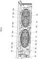
FIGS. 3 and7 , a thin vertically elongated substantially rectangular cushion member (a buffer member) 80, whose shape follows thefirst beam 52b and thesecond beam 52c, is disposed on a front surface of a substantially central portion of the opening area 53 (between thefirst cover 50 and thesaran net 70, which will be described later) . That is, thecushion member 80 is disposed in such a manner as to lie along a non-opening portion of theopening area 53 and has, at a central portion thereof, a bent beam-shaped portion (a beam-shaped portion) 80a, which is bent substantially into a collapsed V-shape along the non-opening portion of theopening area 53 at the sound radiation center C of thespeaker 10. As a result, thecushion member 80 is disposed in the position which is superposed above the sound radiation center C of thespeaker 10. Thecushion member 80 is formed of a foamed urethane, elastomer, silicone, or the like, and has a thickness of, for example, 1 mm. Thecushion member 80 is affixed to thefirst beam 52b and thesecond beam 52c with an adhesive or the like. Thus, thecushion member 80 can increase an in-plane strength in a plan view by incorporating the bent beam-shaped portion 80a described above, thereby making it possible to improve the working efficiency in affixing thecushion member 80 to thefirst cover 50. - As shown in
FIGS. 2 and7 , thesecond cover 60 is made of a synthetic resin, constitutes a horizontally elongated rectangular plate-shaped member whose front surface is made into a flat plane, and is disposed in such a manner as to cover the front side of thespeaker apparatus 1 excluding portions corresponding to thepower supply switches 24, theterminal panel 30, and thesound radiation ports 10a of the fourspeakers 10. Then, thesecond cover 60 has sound radiation port openingportions 60a formed in positions which are superposed above thesound radiation ports 10a of the fourspeakers 10 in such a manner as to face individually the corresponding sound radiation ports . In other words, thesecond cover 60 is provided to surround individually the openingareas 53 in the first covers 50 in such a manner as to be superposed on sides of thefirst cover 50 which are opposite to the sides thereof which face thespeakers 10. As a result, sound radiated from eachspeaker 10 is prevented from being interrupted by thesecond cover 60. - As shown in
FIG. 5 , specifically speaking, thesecond cover 60 is disposed so that thesecond cover 60 is brought into abutment with front surfaces of the plate-shapedportion 56 and the frame-shapedportion 54 of thefirst cover 50 and that the sound radiationport opening portions 60a thereof lie in the vicinity of theouter edge portions 52a of themesh portions 52 of thefirst cover 50. With thesecond cover 60 disposed on the front surface side of thefirst cover 50, a front surface of thesecond cover 60 is positioned further forwards (further upwards inFIG. 5 ) than themesh portions 52 of thefirst cover 50. - The
saran net 70 is formed of chemical fibers of, for example, polyester or the like, so that thesaran net 70 constitutes a member whose transmission loss of sound radiated from eachspeaker 10 is small (a member having a superior sound transmission capability) . Thesaran net 70 has a horizontally elongated rectangular shape and is one size larger than thesecond cover 60 as a whole. As shown inFIGS. 6A and 6B , thesaran net 70 is provided in such a manner as to be bonded to the front surface of thesecond cover 60, which is formed into the flat plane, side surfaces of thesecond cover 60, and a part of a rear surface of thesecond cover 60, whereby thesaran net 70 covers the front surface and side surfaces of thesecond cover 60 and the mesh portions 52 (thesound radiation ports 10a of the speakers 10) of thefirst cover 50. Thesaran net 70 and themesh portions 52 of thefirst cover 50 are spaced apart from each other (over an area where thesaran net 70 and thefirst cover 50 are superposed on each other) to thereby define a gap D1 of, for example, 2 mm therebetween. Thesaran net 70 and thecushion member 80 lie close to each other to thereby define a gap of, for example, 1 mm therebetween. Thus, as is described above, thesaran net 70 is supported on a side thereof which faces thesound radiation ports 10a of thespeakers 10 by the two members of thefirst cover 50 and thesecond cover 60. - Next, referring to
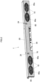
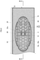
FIGS. 6A and 6B , a bonding mode of bonding thesaran net 70 to thesecond cover 60 will be described in detail. An area A1 on the front surface of thesecond cover 60 which excludes areas surrounding the sound radiationport opening portions 60a (portions which are superposed on the openingareas 53 in the first cover 50) and thesaran net 70 are bonded together with a first adhesive B1. The first adhesive B1 is, for example, an adhesive in the form of a solvent of a styrene-butadiene rubber family having a low viscosity. On the other hand, areas A2 on the front surface of thesecond member 60 which correspond to the areas surrounding the sound radiationport opening portions 60a (the portions which are superposed on the openingareas 53 in the first cover 50) and thesaran net 70 are bonded together with a second adhesive B2, which has a bonding strength higher than that of the adhesive B1. The second adhesive B2 is, for example, an adhesive in the form of a solvent of a chloroprene rubber family having a high viscosity. Here, the fact that an adhesive has a higher bonding strength means that one has to have more difficulty in separating things bonded together with the adhesive once it has set. States of the first adhesive B1 and the second adhesive B2 include states before and after the adhesives have set. - Since the areas A2 on the front surface of the
second cover 60 which surround the sound radiationport opening portions 60a and thesaran net 70 are bonded together with the adhesive B2 having the superior bonding strength in the way described above, portions of thesaran net 70 which are superposed above the sound radiationport opening portions 60a, that is, areas A3 of thesaran net 70 which are surrounded by the portions bonded with the second adhesive B2 are in such a state that a saran material is stretched due to tension exerted thereon. Here, the state in which thesaran net 70 is stretched due to tension exerted thereon means a state in which almost no wrinkle or looseness is visible on thesaran net 70, which exhibits a large spring-back force (resilient restoration force) when thesaran net 70 is depressed down. - Next, a fabrication method of the
speaker apparatus 1 according to the present application example will be described. A known speaker apparatus fabrication method can be applied to a step of assembling the housing including theupper panel 20 and a step of assembling the control circuit board and the like into thespeaker apparatus 1, and hence, the description of those steps will be omitted here. In the present fabrication method, firstly, thefirst cover 50 is disposed in front of thespeakers 10 in such a manner that the openingareas 53 in thefirst cover 50 are superposed above thesound radiation ports 10a of thespeakers 10 and is then assembled to the housing of the speaker apparatus 1 (a first disposition step). Subsequently, thesecond cover 60 is disposed in front of thefirst cover 50 in such a manner as to surround theopening areas 53 of the first cover 50 (a second disposition step) . That is, thesecond cover 60 is disposed in front of thefirst cover 50 in such a manner that the sound radiationport opening portions 60a of thesecond cover 60 are superposed above the openingareas 53 of thefirst cover 50 and is then assembled to thefirst cover 50. - Next, the first adhesive B1 is sprayed on to the area A1 and the areas A2 (refer to
FIGS. 6A and 6B ) using a spray device. Subsequently, the second adhesive B2, whose bonding strength is higher than that of the first adhesive B1, is applied to the areas A2 (refer toFIGS. 6A and 6B ) surrounding the sound radiationport opening portions 60a on the front surface of thesecond cover 60 using a brush or the like. Subsequently, thesaran net 70 is bonded to the area A1 to which the first adhesive B1 is applied and the areas A2 to which the first adhesive B1 and the second adhesive B2 are applied, and the front sides of thefirst cover 50 and thesecond cover 60 are covered by thesaran net 70 so bonded (a bonding step). - In bonding the
saran net 70, thesaran net 70 is bonded to thesecond cover 60 in such a state that the portions of thesaran net 70 which are superposed above the sound radiationport opening portions 60a, that is, the areas A3 (refer toFIGS. 6A and 6B ) surrounded by the portions which are bonded with the second adhesive B2 are stretched due to tension exerted thereto. The exertion of tension on to thesaran net 70 can be executed, for example, by stretching thesaran net 70 with a uniform force exerted from the circumferences of the areas A2 to which the second adhesive B2 is applied. - Here, in the case that only the second adhesive B2 having the high bonding strength is used, the working efficiency of the step of bonding the
saran net 70 is deteriorated. The step of bonding thesaran net 70 is not such a step that tension is exerted on the whole surface of the saran net 70 so as to bond thesaran net 70 altogether at one time, but in an actual step of bonding thesaran net 70, tension is exerted manually on to portions of the saran net 70 a bit by a bit. In the case that the adhesive is erroneously applied to portions of thesaran net 70 which are not desired to be bonded, in the event that the adhesive used is the second adhesive B2 having the high bonding strength, the resulting bonding effect will become too strong undesirably. On the other hand, in the case that only the first adhesive B1 having the low bonding strength is used, although large tension is required to prevent an occurrence of resonance in thesaran net 70, the required large tension cannot be secured only with the first adhesive B1 having the low bonding strength. Then, large tension can be exerted on to thesaran net 70 while securing the working efficiency of the bonding step of thesaran net 70 by using the two types of adhesives in the way described above. - As described heretofore, with the
speaker apparatus 1 according to the present application example, thefirst cover 50 is provided in such a manner that the openingareas 53 are superposed above thesound radiation ports 10a of thespeakers 10, thesecond cover 60 is provided on the side of thefirst cover 50 which is opposite to the side thereof which faces thespeakers 10 in such a manner that the sound radiationport opening portions 60a are superposed above the openingareas 53, and thesaran net 70 is provided to cover thefirst cover 50 and the side (the front side) of thesecond cover 60 which is opposite to the side thereof which faces thespeakers 10 while being bonded to thesecond cover 60. As a result, thesaran net 70 is supported on the side thereof which faces thesound radiation ports 10a of thespeakers 10 by the two members of thefirst cover 50 and thesecond cover 60. By adopting this configuration, the sufficient gap is secured between thesound radiation ports 10a of thespeakers 10 and the openingareas 53 of thefirst cover 50, and thesaran net 70. - Further, with the
speaker apparatus 1 according to the present application example, thesecond cover 60 and thesaran net 70 are bonded together with the first adhesive B1 at the area A1, and thesecond cover 60 and thesaran net 70 are bonded together with the second adhesive B2, which has the higher bonding strength than that of the first adhesive B1, at the areas A2 on the front surface of thesecond cover 60 which surround the circumferences the sound radiationport opening portions 60a. By adopting this configuration, the large tension is exerted on the areas A3 which are surrounded by the portions bonded with the second adhesive B2, compared with the area A1 which is bonded with the first adhesive B1. Thus, with thespeaker apparatus 1 according to the present application example, the large tension can be exerted on thesaran net 70 while securing the sufficient gap between thesound radiation ports 10a of thespeakers 10 and thesaran net 70, thereby making it possible to prevent or suppress the occurrence of resonance in thesaran net 70. - In addition, with the
speaker apparatus 1, thesaran net 70 is bonded to thesecond cover 60 with the tension exerted on at least the areas A3 which are surrounded by the portions bonded with the second adhesive B2. As a result, the larger tension can be exerted on thesaran net 70 at the areas A3, thereby making it possible to prevent or suppress the occurrence of resonance in thespeaker apparatus 1 more effectively. - With the
speaker apparatus 1, the areas of thesaran net 70 which are superposed above the openingareas 53 of thefirst cover 50 are spaced apart from therelevant opening areas 53. As a result, the specific configuration to secure the sufficient gap between the openingareas 53 of thefirst cover 50 and thesaran net 70 can be provided. - With the
speaker apparatus 1, theopening area 53 of the first member or thefirst cover 50 includes theopening portion 53a which is provided in the position which is superposed above the sound radiation center C of thespeaker 10. As a result, since sound radiated from the sound radiation center C where sound becomes largest in magnitude passes through thisopening portion 53a, sound radiated from thespeaker 10 can be prevented from being lost or interrupted by thefirst cover 50. - With the
speaker apparatus 1, thecushion member 80 is provided to be disposed between thefirst cover 50 and thesaran net 70 while being bonded to thefirst cover 50. As a result, vibrations of thefirst cover 50 generated by sound radiated from thespeakers 10 can be suppressed by thecushion member 80, thereby making it possible to prevent or suppress the occurrence of resonance in thespeaker apparatus 1 effectively. - In addition, with the
speaker apparatus 1, thecushion member 80 is bonded to thefirst cover 50 in such a manner as to lie along the non-opening portion of theopening area 53 of thefirst cover 50. As a result, vibrations of thefirst cover 50 in association with sound radiated from thespeakers 10 can be suppressed further by thecushion member 80, thereby making it possible to prevent or suppress the occurrence of resonance in thespeaker apparatus 1 more effectively. - With the
speaker apparatus 1, theopening area 53 of thefirst cover 50 is provided by thefirst beam 52b and thesecond beam 52c, and thecushion member 80 is bonded to the first cover while lying along thefirst beam 52b and thesecond beam 52c. This can provide the specific configuration to dispose thecushion member 80 in such a manner as to lie along the non-opening portion of the openingportion 53. - With the
speaker apparatus 1, thecushion member 80 has the bent beam-shapedportion 80a which is provided to lie along the non-opening portion at the sound radiation center C of thespeaker 10. As a result, since the bent beam-shapedportion 80a functions as a beam on thecushion member 80, the in-plane strength of thecushion member 80 in the plan view can be increased, and further, the working efficiency in affixing thecushion member 80 to thefirst cover 50 can also be improved. - In addition, with the
speaker apparatus 1, thecushion member 80 and thesaran net 70 are disposed close to each other. As a result, in the case that thesaran net 70 vibrates, thesaran net 70 comes to interfere with thecushion member 80, whereby the vibration of thesaran net 70 is absorbed by thecushion member 80, thereby making it possible to prevent or suppress the occurrence of resonance in thesaran net 70 more effectively. - Further, the
electronic keyboard instrument 100 which constitutes an electronic musical instrument having thespeaker apparatus 1 can prevent or suppress the occurrence of resonance effectively at the time of sound radiation, thereby making it possible to make sound radiation of good quality. - The fabrication method of the
speaker apparatus 1 includes the first disposition step of disposing thefirst cover 50 having the openingareas 53 each made up of the multiple opening portions in such a manner that the openingareas 53 are superposed above the correspondingsound radiation ports 10a of thespeakers 10, the second disposition step of disposing thesecond cover 60 to be superposed on the side of thefirst cover 50 which is opposite to the side thereof which faces thespeakers 10 in such a manner as to surround theopening areas 53 of thefirst cover 50, and the bonding step of bonding thesaran net 70 to thesecond cover 60 in such a manner as to cover thefirst cover 50 and the side of thesecond cover 60 which is opposite to the side thereof which faces thespeakers 10. In the bonding step, thesecond cover 60 and thesaran net 70 are bonded together at the area A1 with the first adhesive B1 and at the areas A2 which surround theopening areas 53 of thefirst cover 50 with the second adhesive B2 having the higher bonding strength than that of the first adhesive B1. - With the fabrication method described above, by executing the first disposition step and the second disposition step, the
first cover 50, thesecond cover 60, and thesaran net 70 can be assembled together with the sufficient gap secured between thesound radiation ports 10a of thespeakers 10 and the openingareas 53 of thefirst cover 50, and thesaran net 70 in the position where thesaran net 70 is superposed above thesound radiation ports 10a of thespeakers 10. Further, by executing the bonding step, thesaran net 70 can be bonded to thesecond cover 60 with the large tension exerted on the areas A3 which are surrounded by the portions bonded with the second adhesive B2, compared with the area A1 bonded with the first adhesive B1. As a result, the large tension is exerted on thesaran net 70 while securing the gap between thesound radiation ports 10a of thespeakers 10 and thesaran net 70, whereby thespeaker apparatus 1 can be fabricated which can prevent or suppress the occurrence of resonance therein. - With the fabrication method of the
speaker apparatus 1, in the bonding step, thesaran net 70 is bonded to thesecond cover 60 with the tension exerted on at least the areas A3 of thesaran net 70 which are surrounded by the portions bonded with the second adhesive B2. As a result, in the bonding step, the larger tension can be exerted on thesaran net 70 at the areas A3, thereby making it possible to fabricate thespeaker apparatus 1 which can prevent or suppress the occurrence of resonance therein more effectively. - Next, referring to
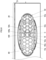
FIG. 8 , a speaker apparatus (sound radiation apparatus)1 according to a modified example of the present disclosure will be described. The modified example of the present disclosure differs in that acushion member 180 has a different shape from that of thecushion member 80 according to the application example of the present disclosure. The other configurations of the modified example are similar to those of the application example of the present disclosure, and hence, the description thereof will be omitted here. As shown inFIG. 8 , in thecushion member 180 according to the modified example of the present disclosure, a portion of theopening area 53 which surrounds theopening portion 53a provided in the position which is superposed above the sound radiation center C of thespeaker 10 does not have the shape that follows thesecond beam 52c but is formed into a straight beam-shaped portion (a beam-shaped portion) 180a having a straight-line shape extending in a left-right direction. Although given the straight-line shape, thecushion member 180 according to the modified example of the present disclosure can provide the same advantageous effect as that of thecushion member 80 according to the application example of the present disclosure. Further, thecushion member 180 of the modified example of the present disclosure incorporates the straight beam-shapedportion 180a described above, thereby making it possible not only to increase the in-plane strength in the plan view but also to improve the working efficiency in affixing thecushion member 180 to thefirst cover 50. - The application example and the modified example which have been described heretofore are presented as the examples, and hence, there is no intention to limit the scope of the present invention by the examples. The novel application example or modified example can be carried out in other various forms, and various omissions, replacements and modifications can be made thereto without departing from the spirit and scope of the present invention. Those resulting application examples and modified examples thereof are included in the scope and gist of the present invention and are also included in the scope of inventions claimed for patent under claims below and their equivalents. For example, in the application example or the modified example, the configuration is exemplified in which the cushion member is disposed above the opening area; however, the application example or the modified example may be applied to a configuration in which the speaker apparatus includes no cushion member. Even with the speaker apparatus having this configuration, large tension can be exerted on the saran net while securing the gap between the sound radiation ports of the speakers and the saran net, thereby making it possible to prevent or suppress the occurrence of resonance in the saran net and thereby provide an electronic musical instrument making sound radiation of good quality.
Claims (15)
- A sound radiation apparatus, comprising:a sound radiation unit (10);a first member (50) having an opening area (53) which is provided in such a manner as to be superposed above at least a sound radiation port (10a) of the sound radiation unit (10) and which is made up of multiple opening portions at a location which is superposed above the sound radiation port (10a);a second member (60) provided to be superposed on a side of the first member (50) which is opposite to a side thereof which faces the sound radiation unit in such a manner as to surround the opening area (53) of the first member (50); anda covering member (70) configured to cover the first member (50) and a side of the second member (60) which is opposite to a side thereof which faces the sound radiation unit and bonded to the second member (60),wherein the second member (60) and the covering member (70) are bonded together at an area (A1) on the second member (60) which excludes a portion surrounding a circumference of the opening area (53) of the first member (50) with a first adhesive (B1) and at an area (A2) on the second member (60) which surrounds the circumference of the opening area (53) of the first member (50) with a second adhesive (B2) having a higher bonding strength than a bonding strength of the first adhesive (B1) .
- The sound radiation apparatus according to claim 1,
wherein the covering member (70) is bonded to the second member (60) with tension exerted on at least an area which is surrounded by a location bonded with the second adhesive (B2) . - The sound radiation apparatus according to claim 1,
wherein the first member (50) comprises:multiple mesh portions (52) provided individually to be superposed above sound radiation ports (10a) of the multiple sound radiation units (10);multiple frame-shaped portions (54) provided individually to surround circumferences of the multiple mesh portions (52) in a frame-like fashion; anda plate-shaped portion (56) of a horizontally elongated plate shape which is provided outside the frame-shaped portions (54) . - The sound radiation apparatus according to claim 3,
wherein the mesh portion (52) comprises:an outer edge portion (52a);a first beam (52b) laid out from the outer edge portion (52a) into a honeycomb structure of a network of meshes of a substantially regular hexagonal shape; anda second beam (52c) laid out from the outer edge portion (52a) in vertical and horizontal directions. - The sound radiation apparatus according to claim 1,
wherein a location of the covering member (70) which is superposed above the opening area (53) of the first member (50) and the first member (50) are spaced apart from each other. - The sound radiation apparatus according to claim 2,
wherein a location of the covering member (70) which is superposed above the opening area (53) of the first member (50) and the first member (50) are spaced apart from each other. - The sound radiation apparatus according to claim 1,
wherein the opening area (53) of the first member (50) comprises an opening portion (53a) provided in a position superposed above a sound radiation center (C) of the sound radiation unit (10). - The sound radiation apparatus according to claim 1, comprising:
a cushion member (80) disposed between the first member (50) and the covering member (70) and bonded to the first member (50) . - The sound radiation apparatus according to claim 8,
wherein the cushion member (80) is bonded to the first member (50) in such a manner as to lie along a non-opening portion of the opening area (53) of the first member (50). - The sound radiation apparatus according to claim 9,wherein the opening area (53) of the first member (50) is provided by a beam, andwherein the cushion member (80) is bonded to the first member (50) in such a manner as to lie along the beam of the first member (50).
- The sound radiation apparatus according to claim 9,
wherein the cushion member (80) has a beam-shaped portion (80a) provided to lie along the non-opening portion at the sound radiation center (C) of the sound radiation unit (10). - The sound radiation apparatus according to claim 8,
wherein the cushion member (80) and the covering member (70) are disposed close to each other. - An electronic musical instrument comprising the sound radiation apparatus according to any one of claims 1 to 12.
- A sound radiation apparatus fabrication method, comprising:a first disposition step of disposing a first member (50) having an opening area (53) made up of multiple opening portions in such a manner that the opening area (53) is superposed above a sound radiation port (10a) of a sound radiation unit (10);a second disposition step of disposing a second member (60) to be disposed on a side of the first member (50) which is opposite to a side thereof which faces the sound radiation unit in such a manner as to surround the opening area (53) of the first member (50); anda bonding step of bonding a covering member (70) to the second member (60) in such a manner as to cover the first member (50) and a side of the second member (60) which is opposite to a side thereof which faces the sound radiation unit,wherein in the bonding step, the second member (60) and the covering member (70) are bonded together at an area (A1) on the second member (60) which excludes a portion surrounding a circumference of the opening area (53) of the first member (50) with a first adhesive and an area (A2) on the second member (60) which surrounds the circumference of the opening area (53) of the first member (50) with a second adhesive (B2) having a higher bonding strength than a bonding strength of the first adhesive (B1).
- The sound radiation apparatus fabrication method according to claim 14,
wherein in the bonding step, the covering member (70) is bonded to the second member (60) with tension exerted on at least an area of the covering member (70) which is surrounded by a location bonded with the second adhesive (B2).
Applications Claiming Priority (2)
| Application Number | Priority Date | Filing Date | Title |
|---|---|---|---|
| JP2021207671 | 2021-12-22 | ||
| JP2022172172A JP7400920B2 (en) | 2021-12-22 | 2022-10-27 | Sound emitting device, electronic musical instrument, and method for manufacturing the sound emitting device |
Publications (2)
| Publication Number | Publication Date |
|---|---|
| EP4202917A1 true EP4202917A1 (en) | 2023-06-28 |
| EP4202917B1 EP4202917B1 (en) | 2024-10-16 |
Family
ID=84537027
Family Applications (1)
| Application Number | Title | Priority Date | Filing Date |
|---|---|---|---|
| EP22213833.1A Active EP4202917B1 (en) | 2021-12-22 | 2022-12-15 | Sound radiation appratus, electronic musical instrument, and sound radiation appratus fabrication method |
Country Status (3)
| Country | Link |
|---|---|
| US (1) | US12185041B2 (en) |
| EP (1) | EP4202917B1 (en) |
| CN (1) | CN116343727A (en) |
Families Citing this family (2)
| Publication number | Priority date | Publication date | Assignee | Title |
|---|---|---|---|---|
| US12003918B2 (en) * | 2020-03-17 | 2024-06-04 | Casio Computer Co., Ltd. | Electronic musical instrument and electronic keyboard instrument |
| JP7452566B2 (en) * | 2022-03-24 | 2024-03-19 | カシオ計算機株式会社 | Cases and keyboard instruments |
Citations (4)
| Publication number | Priority date | Publication date | Assignee | Title |
|---|---|---|---|---|
| US20120134518A1 (en) * | 2010-11-25 | 2012-05-31 | Kyocera Corporation | Cover unit covering openings and an electronic device provided with the cover unit |
| US8939252B2 (en) * | 2012-11-11 | 2015-01-27 | David Sanborn | Protective material for acoustic transmission |
| JP2019068146A (en) | 2017-09-28 | 2019-04-25 | ヤマハ株式会社 | Sound emission structure |
| US20200213692A1 (en) * | 2018-12-28 | 2020-07-02 | AAC Technologies Pte. Ltd. | Speaker box and mobile terminal device using same |
Family Cites Families (23)
| Publication number | Priority date | Publication date | Assignee | Title |
|---|---|---|---|---|
| JPS6189798A (en) * | 1984-10-08 | 1986-05-07 | Nishida Tekko Kk | Acoustic device with loudspeaker |
| JPH09331592A (en) * | 1996-06-10 | 1997-12-22 | Harumitsu Matsushita | Speaker and saran net or cover for speaker |
| JP3512714B2 (en) * | 2000-07-03 | 2004-03-31 | Necビューテクノロジー株式会社 | Speaker system |
| JP2004147125A (en) * | 2002-10-24 | 2004-05-20 | Sanyo Electric Co Ltd | Speaker |
| JP2005266176A (en) * | 2004-03-17 | 2005-09-29 | Kawai Musical Instr Mfg Co Ltd | Electronic keyboard instrument |
| JP4239971B2 (en) * | 2004-12-28 | 2009-03-18 | ヤマハ株式会社 | Electronic keyboard instrument |
| JP4390760B2 (en) * | 2005-09-30 | 2009-12-24 | シャープ株式会社 | Speaker device and display device |
| JP5200450B2 (en) * | 2006-09-21 | 2013-06-05 | ヤマハ株式会社 | Electronic keyboard instrument |
| JP2008310055A (en) * | 2007-06-14 | 2008-12-25 | Kawai Musical Instr Mfg Co Ltd | Musical sound device and production method and modification method of musical sound device |
| JP2010176110A (en) * | 2009-01-30 | 2010-08-12 | Kunio Kido | Voice correcting apparatus |
| JP4930802B2 (en) * | 2009-05-18 | 2012-05-16 | カシオ計算機株式会社 | Keyboard instrument |
| US8502062B2 (en) * | 2010-07-12 | 2013-08-06 | Yamaha Corporation | Electronic keyboard musical instrument |
| JP5658648B2 (en) * | 2011-11-17 | 2015-01-28 | 富士通フロンテック株式会社 | Speaker mounting apparatus and information processing apparatus |
| EP2615606A3 (en) * | 2012-01-13 | 2016-08-10 | Yamaha Corporation | Speaker unit for musical instrument |
| JP5909146B2 (en) * | 2012-04-27 | 2016-04-26 | 株式会社河合楽器製作所 | Electronic keyboard instrument |
| JP5516646B2 (en) * | 2012-05-17 | 2014-06-11 | カシオ計算機株式会社 | Keyboard device |
| JP2014143465A (en) * | 2013-01-22 | 2014-08-07 | Sanyo Electric Co Ltd | Grille for speaker, speaker device, and acoustic device |
| JP2015132641A (en) * | 2014-01-09 | 2015-07-23 | ヤマハ株式会社 | Electronic keyboard instrument |
| JP6413594B2 (en) * | 2014-10-10 | 2018-10-31 | ヤマハ株式会社 | Speaker box structure of electronic equipment |
| JP6541988B2 (en) * | 2015-02-25 | 2019-07-10 | 京セラ株式会社 | Electronics |
| JP6555644B2 (en) * | 2016-12-22 | 2019-08-07 | カシオ計算機株式会社 | Keyboard instrument |
| CN211052771U (en) * | 2019-10-29 | 2020-07-21 | 泰州双华数控机床有限公司 | Novel fast wire cutting machine tool |
| JP7509163B2 (en) * | 2022-03-24 | 2024-07-02 | カシオ計算機株式会社 | Electronic keyboard instruments |
-
2022
- 2022-12-15 EP EP22213833.1A patent/EP4202917B1/en active Active
- 2022-12-16 CN CN202211623640.9A patent/CN116343727A/en active Pending
- 2022-12-16 US US18/082,741 patent/US12185041B2/en active Active
Patent Citations (4)
| Publication number | Priority date | Publication date | Assignee | Title |
|---|---|---|---|---|
| US20120134518A1 (en) * | 2010-11-25 | 2012-05-31 | Kyocera Corporation | Cover unit covering openings and an electronic device provided with the cover unit |
| US8939252B2 (en) * | 2012-11-11 | 2015-01-27 | David Sanborn | Protective material for acoustic transmission |
| JP2019068146A (en) | 2017-09-28 | 2019-04-25 | ヤマハ株式会社 | Sound emission structure |
| US20200213692A1 (en) * | 2018-12-28 | 2020-07-02 | AAC Technologies Pte. Ltd. | Speaker box and mobile terminal device using same |
Non-Patent Citations (2)
| Title |
|---|
| DATABASE COMPENDEX [online] ENGINEERING INFORMATION, INC., NEW YORK, NY, US; 2 March 2021 (2021-03-02), ROSKOWICZ M ET AL: "The effect of adhesive layer thickness on joint static strength", XP002809265, Database accession no. E20211410167498 * |
| ROSKOWICZ M ET AL: "The effect of adhesive layer thickness on joint static strength", MATERIALS 20210302 MDPI AG CHE, vol. 14, no. 6, 2 March 2021 (2021-03-02), DOI: 10.3390/MA14061499 * |
Also Published As
| Publication number | Publication date |
|---|---|
| CN116343727A (en) | 2023-06-27 |
| US20230199352A1 (en) | 2023-06-22 |
| JP2024020618A (en) | 2024-02-14 |
| US12185041B2 (en) | 2024-12-31 |
| EP4202917B1 (en) | 2024-10-16 |
Similar Documents
| Publication | Publication Date | Title |
|---|---|---|
| US8818006B2 (en) | Speaker system, electronic apparatus using same, and mobile body device | |
| EP4202917B1 (en) | Sound radiation appratus, electronic musical instrument, and sound radiation appratus fabrication method | |
| KR20190074540A (en) | Display apparatus | |
| US20120051557A1 (en) | Voice coil for speaker device, and speaker device | |
| KR20180062320A (en) | Display device | |
| KR20070084055A (en) | Display devices, including panel acoustic transducers, and transparent panel acoustic transducers | |
| US11962972B2 (en) | Display device and speaker | |
| JP2004343362A (en) | Planar speaker | |
| JP4437106B2 (en) | Flat speaker and speaker-integrated display device | |
| JP7784482B2 (en) | Acoustic devices and transportation devices containing the same | |
| JP7861775B2 (en) | Sound emission device, electronic musical instrument, and method for manufacturing a sound emission device | |
| JP7400920B2 (en) | Sound emitting device, electronic musical instrument, and method for manufacturing the sound emitting device | |
| KR20240177256A (en) | Sound apparatus and vehicular apparatus comprising the same | |
| KR20240177257A (en) | Sound apparatus and vehicular apparatus comprising the same | |
| EP1408717B1 (en) | Combination loudspeaker unit | |
| JP7847181B2 (en) | Acoustic devices and transport devices including the same | |
| US20250159391A1 (en) | Sound apparatus and vehicular apparatus including the same | |
| US20250159392A1 (en) | Sound apparatus and vehicular apparatus including the same | |
| JPH11205881A (en) | Loudspeaker system | |
| KR102195130B1 (en) | Sound producing actuator | |
| KR20250072758A (en) | Sound apparatus and vehicular apparatus comprising the same | |
| KR20240177255A (en) | Sound apparatus and vehicular apparatus comprising the same | |
| KR20240177258A (en) | Sound apparatus and vehicular apparatus comprising the same | |
| WO2022186307A1 (en) | Electronic musical instrument | |
| KR20250146880A (en) | Sound apparatus and vehicular apparatus comprising the same |
Legal Events
| Date | Code | Title | Description |
|---|---|---|---|
| PUAI | Public reference made under article 153(3) epc to a published international application that has entered the european phase |
Free format text: ORIGINAL CODE: 0009012 |
|
| STAA | Information on the status of an ep patent application or granted ep patent |
Free format text: STATUS: REQUEST FOR EXAMINATION WAS MADE |
|
| 17P | Request for examination filed |
Effective date: 20221220 |
|
| AK | Designated contracting states |
Kind code of ref document: A1 Designated state(s): AL AT BE BG CH CY CZ DE DK EE ES FI FR GB GR HR HU IE IS IT LI LT LU LV MC ME MK MT NL NO PL PT RO RS SE SI SK SM TR |
|
| GRAP | Despatch of communication of intention to grant a patent |
Free format text: ORIGINAL CODE: EPIDOSNIGR1 |
|
| STAA | Information on the status of an ep patent application or granted ep patent |
Free format text: STATUS: GRANT OF PATENT IS INTENDED |
|
| INTG | Intention to grant announced |
Effective date: 20240522 |
|
| GRAS | Grant fee paid |
Free format text: ORIGINAL CODE: EPIDOSNIGR3 |
|
| GRAA | (expected) grant |
Free format text: ORIGINAL CODE: 0009210 |
|
| STAA | Information on the status of an ep patent application or granted ep patent |
Free format text: STATUS: THE PATENT HAS BEEN GRANTED |
|
| AK | Designated contracting states |
Kind code of ref document: B1 Designated state(s): AL AT BE BG CH CY CZ DE DK EE ES FI FR GB GR HR HU IE IS IT LI LT LU LV MC ME MK MT NL NO PL PT RO RS SE SI SK SM TR |
|
| REG | Reference to a national code |
Ref country code: GB Ref legal event code: FG4D |
|
| REG | Reference to a national code |
Ref country code: DE Ref legal event code: R096 Ref document number: 602022006861 Country of ref document: DE Ref country code: CH Ref legal event code: EP |
|
| REG | Reference to a national code |
Ref country code: IE Ref legal event code: FG4D |
|
| REG | Reference to a national code |
Ref country code: LT Ref legal event code: MG9D |
|
| REG | Reference to a national code |
Ref country code: NL Ref legal event code: MP Effective date: 20241016 |
|
| REG | Reference to a national code |
Ref country code: AT Ref legal event code: MK05 Ref document number: 1733600 Country of ref document: AT Kind code of ref document: T Effective date: 20241016 |
|
| PG25 | Lapsed in a contracting state [announced via postgrant information from national office to epo] |
Ref country code: NL Free format text: LAPSE BECAUSE OF FAILURE TO SUBMIT A TRANSLATION OF THE DESCRIPTION OR TO PAY THE FEE WITHIN THE PRESCRIBED TIME-LIMIT Effective date: 20241016 |
|
| PG25 | Lapsed in a contracting state [announced via postgrant information from national office to epo] |
Ref country code: NL Free format text: LAPSE BECAUSE OF FAILURE TO SUBMIT A TRANSLATION OF THE DESCRIPTION OR TO PAY THE FEE WITHIN THE PRESCRIBED TIME-LIMIT Effective date: 20241016 |
|
| PG25 | Lapsed in a contracting state [announced via postgrant information from national office to epo] |
Ref country code: IS Free format text: LAPSE BECAUSE OF FAILURE TO SUBMIT A TRANSLATION OF THE DESCRIPTION OR TO PAY THE FEE WITHIN THE PRESCRIBED TIME-LIMIT Effective date: 20250216 Ref country code: PT Free format text: LAPSE BECAUSE OF FAILURE TO SUBMIT A TRANSLATION OF THE DESCRIPTION OR TO PAY THE FEE WITHIN THE PRESCRIBED TIME-LIMIT Effective date: 20250217 Ref country code: HR Free format text: LAPSE BECAUSE OF FAILURE TO SUBMIT A TRANSLATION OF THE DESCRIPTION OR TO PAY THE FEE WITHIN THE PRESCRIBED TIME-LIMIT Effective date: 20241016 |
|
| PG25 | Lapsed in a contracting state [announced via postgrant information from national office to epo] |
Ref country code: FI Free format text: LAPSE BECAUSE OF FAILURE TO SUBMIT A TRANSLATION OF THE DESCRIPTION OR TO PAY THE FEE WITHIN THE PRESCRIBED TIME-LIMIT Effective date: 20241016 |
|
| PG25 | Lapsed in a contracting state [announced via postgrant information from national office to epo] |
Ref country code: BG Free format text: LAPSE BECAUSE OF FAILURE TO SUBMIT A TRANSLATION OF THE DESCRIPTION OR TO PAY THE FEE WITHIN THE PRESCRIBED TIME-LIMIT Effective date: 20241016 |
|
| PG25 | Lapsed in a contracting state [announced via postgrant information from national office to epo] |
Ref country code: ES Free format text: LAPSE BECAUSE OF FAILURE TO SUBMIT A TRANSLATION OF THE DESCRIPTION OR TO PAY THE FEE WITHIN THE PRESCRIBED TIME-LIMIT Effective date: 20241016 |
|
| PG25 | Lapsed in a contracting state [announced via postgrant information from national office to epo] |
Ref country code: NO Free format text: LAPSE BECAUSE OF FAILURE TO SUBMIT A TRANSLATION OF THE DESCRIPTION OR TO PAY THE FEE WITHIN THE PRESCRIBED TIME-LIMIT Effective date: 20250116 |
|
| PG25 | Lapsed in a contracting state [announced via postgrant information from national office to epo] |
Ref country code: LV Free format text: LAPSE BECAUSE OF FAILURE TO SUBMIT A TRANSLATION OF THE DESCRIPTION OR TO PAY THE FEE WITHIN THE PRESCRIBED TIME-LIMIT Effective date: 20241016 Ref country code: AT Free format text: LAPSE BECAUSE OF FAILURE TO SUBMIT A TRANSLATION OF THE DESCRIPTION OR TO PAY THE FEE WITHIN THE PRESCRIBED TIME-LIMIT Effective date: 20241016 Ref country code: GR Free format text: LAPSE BECAUSE OF FAILURE TO SUBMIT A TRANSLATION OF THE DESCRIPTION OR TO PAY THE FEE WITHIN THE PRESCRIBED TIME-LIMIT Effective date: 20250117 |
|
| PG25 | Lapsed in a contracting state [announced via postgrant information from national office to epo] |
Ref country code: PL Free format text: LAPSE BECAUSE OF FAILURE TO SUBMIT A TRANSLATION OF THE DESCRIPTION OR TO PAY THE FEE WITHIN THE PRESCRIBED TIME-LIMIT Effective date: 20241016 |
|
| PG25 | Lapsed in a contracting state [announced via postgrant information from national office to epo] |
Ref country code: RS Free format text: LAPSE BECAUSE OF FAILURE TO SUBMIT A TRANSLATION OF THE DESCRIPTION OR TO PAY THE FEE WITHIN THE PRESCRIBED TIME-LIMIT Effective date: 20250116 |
|
| PG25 | Lapsed in a contracting state [announced via postgrant information from national office to epo] |
Ref country code: SM Free format text: LAPSE BECAUSE OF FAILURE TO SUBMIT A TRANSLATION OF THE DESCRIPTION OR TO PAY THE FEE WITHIN THE PRESCRIBED TIME-LIMIT Effective date: 20241016 |
|
| PG25 | Lapsed in a contracting state [announced via postgrant information from national office to epo] |
Ref country code: MC Free format text: LAPSE BECAUSE OF FAILURE TO SUBMIT A TRANSLATION OF THE DESCRIPTION OR TO PAY THE FEE WITHIN THE PRESCRIBED TIME-LIMIT Effective date: 20241016 |
|
| PG25 | Lapsed in a contracting state [announced via postgrant information from national office to epo] |
Ref country code: DK Free format text: LAPSE BECAUSE OF FAILURE TO SUBMIT A TRANSLATION OF THE DESCRIPTION OR TO PAY THE FEE WITHIN THE PRESCRIBED TIME-LIMIT Effective date: 20241016 |
|
| REG | Reference to a national code |
Ref country code: DE Ref legal event code: R097 Ref document number: 602022006861 Country of ref document: DE |
|
| PG25 | Lapsed in a contracting state [announced via postgrant information from national office to epo] |
Ref country code: EE Free format text: LAPSE BECAUSE OF FAILURE TO SUBMIT A TRANSLATION OF THE DESCRIPTION OR TO PAY THE FEE WITHIN THE PRESCRIBED TIME-LIMIT Effective date: 20241016 |
|
| PG25 | Lapsed in a contracting state [announced via postgrant information from national office to epo] |
Ref country code: RO Free format text: LAPSE BECAUSE OF FAILURE TO SUBMIT A TRANSLATION OF THE DESCRIPTION OR TO PAY THE FEE WITHIN THE PRESCRIBED TIME-LIMIT Effective date: 20241016 |
|
| PG25 | Lapsed in a contracting state [announced via postgrant information from national office to epo] |
Ref country code: SK Free format text: LAPSE BECAUSE OF FAILURE TO SUBMIT A TRANSLATION OF THE DESCRIPTION OR TO PAY THE FEE WITHIN THE PRESCRIBED TIME-LIMIT Effective date: 20241016 |
|
| PG25 | Lapsed in a contracting state [announced via postgrant information from national office to epo] |
Ref country code: CZ Free format text: LAPSE BECAUSE OF FAILURE TO SUBMIT A TRANSLATION OF THE DESCRIPTION OR TO PAY THE FEE WITHIN THE PRESCRIBED TIME-LIMIT Effective date: 20241016 |
|
| PG25 | Lapsed in a contracting state [announced via postgrant information from national office to epo] |
Ref country code: IT Free format text: LAPSE BECAUSE OF FAILURE TO SUBMIT A TRANSLATION OF THE DESCRIPTION OR TO PAY THE FEE WITHIN THE PRESCRIBED TIME-LIMIT Effective date: 20241016 |
|
| PG25 | Lapsed in a contracting state [announced via postgrant information from national office to epo] |
Ref country code: LU Free format text: LAPSE BECAUSE OF NON-PAYMENT OF DUE FEES Effective date: 20241215 |
|
| PLBE | No opposition filed within time limit |
Free format text: ORIGINAL CODE: 0009261 |
|
| STAA | Information on the status of an ep patent application or granted ep patent |
Free format text: STATUS: NO OPPOSITION FILED WITHIN TIME LIMIT |
|
| PG25 | Lapsed in a contracting state [announced via postgrant information from national office to epo] |
Ref country code: SE Free format text: LAPSE BECAUSE OF FAILURE TO SUBMIT A TRANSLATION OF THE DESCRIPTION OR TO PAY THE FEE WITHIN THE PRESCRIBED TIME-LIMIT Effective date: 20241016 |
|
| 26N | No opposition filed |
Effective date: 20250717 |
|
| REG | Reference to a national code |
Ref country code: BE Ref legal event code: MM Effective date: 20241231 |
|
| PG25 | Lapsed in a contracting state [announced via postgrant information from national office to epo] |
Ref country code: BE Free format text: LAPSE BECAUSE OF NON-PAYMENT OF DUE FEES Effective date: 20241231 |
|
| PG25 | Lapsed in a contracting state [announced via postgrant information from national office to epo] |
Ref country code: IE Free format text: LAPSE BECAUSE OF NON-PAYMENT OF DUE FEES Effective date: 20241215 |
|
| PGFP | Annual fee paid to national office [announced via postgrant information from national office to epo] |
Ref country code: DE Payment date: 20251028 Year of fee payment: 4 |
|
| PGFP | Annual fee paid to national office [announced via postgrant information from national office to epo] |
Ref country code: FR Payment date: 20251110 Year of fee payment: 4 |