EP4202601A1 - Electronic apparatus - Google Patents
Electronic apparatus Download PDFInfo
- Publication number
- EP4202601A1 EP4202601A1 EP22199788.5A EP22199788A EP4202601A1 EP 4202601 A1 EP4202601 A1 EP 4202601A1 EP 22199788 A EP22199788 A EP 22199788A EP 4202601 A1 EP4202601 A1 EP 4202601A1
- Authority
- EP
- European Patent Office
- Prior art keywords
- chassis
- electronic apparatus
- fin
- fan
- processing device
- Prior art date
- Legal status (The legal status is an assumption and is not a legal conclusion. Google has not performed a legal analysis and makes no representation as to the accuracy of the status listed.)
- Pending
Links
Images





Classifications
-
- H—ELECTRICITY
- H05—ELECTRIC TECHNIQUES NOT OTHERWISE PROVIDED FOR
- H05K—PRINTED CIRCUITS; CASINGS OR CONSTRUCTIONAL DETAILS OF ELECTRIC APPARATUS; MANUFACTURE OF ASSEMBLAGES OF ELECTRICAL COMPONENTS
- H05K7/00—Constructional details common to different types of electric apparatus
- H05K7/20—Modifications to facilitate cooling, ventilating, or heating
- H05K7/20009—Modifications to facilitate cooling, ventilating, or heating using a gaseous coolant in electronic enclosures
- H05K7/20136—Forced ventilation, e.g. by fans
- H05K7/20172—Fan mounting or fan specifications
-
- H—ELECTRICITY
- H05—ELECTRIC TECHNIQUES NOT OTHERWISE PROVIDED FOR
- H05K—PRINTED CIRCUITS; CASINGS OR CONSTRUCTIONAL DETAILS OF ELECTRIC APPARATUS; MANUFACTURE OF ASSEMBLAGES OF ELECTRICAL COMPONENTS
- H05K7/00—Constructional details common to different types of electric apparatus
- H05K7/14—Mounting supporting structure in casing or on frame or rack
-
- G—PHYSICS
- G06—COMPUTING OR CALCULATING; COUNTING
- G06F—ELECTRIC DIGITAL DATA PROCESSING
- G06F1/00—Details not covered by groups G06F3/00 - G06F13/00 and G06F21/00
- G06F1/16—Constructional details or arrangements
- G06F1/20—Cooling means
-
- G—PHYSICS
- G06—COMPUTING OR CALCULATING; COUNTING
- G06F—ELECTRIC DIGITAL DATA PROCESSING
- G06F1/00—Details not covered by groups G06F3/00 - G06F13/00 and G06F21/00
- G06F1/16—Constructional details or arrangements
- G06F1/18—Packaging or power distribution
- G06F1/181—Enclosures
-
- G—PHYSICS
- G06—COMPUTING OR CALCULATING; COUNTING
- G06F—ELECTRIC DIGITAL DATA PROCESSING
- G06F1/00—Details not covered by groups G06F3/00 - G06F13/00 and G06F21/00
- G06F1/16—Constructional details or arrangements
- G06F1/18—Packaging or power distribution
- G06F1/183—Internal mounting support structures, e.g. for supporting printed circuit boards
- G06F1/184—Mounting of motherboards
-
- H—ELECTRICITY
- H04—ELECTRIC COMMUNICATION TECHNIQUE
- H04R—LOUDSPEAKERS, MICROPHONES, GRAMOPHONE PICK-UPS OR LIKE ACOUSTIC ELECTROMECHANICAL TRANSDUCERS; ELECTRIC HEARING AIDS; PUBLIC ADDRESS SYSTEMS
- H04R1/00—Details of transducers, loudspeakers or microphones
- H04R1/02—Casings; Cabinets ; Supports therefor; Mountings therein
- H04R1/021—Casings; Cabinets ; Supports therefor; Mountings therein incorporating only one transducer
-
- H—ELECTRICITY
- H04—ELECTRIC COMMUNICATION TECHNIQUE
- H04R—LOUDSPEAKERS, MICROPHONES, GRAMOPHONE PICK-UPS OR LIKE ACOUSTIC ELECTROMECHANICAL TRANSDUCERS; ELECTRIC HEARING AIDS; PUBLIC ADDRESS SYSTEMS
- H04R1/00—Details of transducers, loudspeakers or microphones
- H04R1/02—Casings; Cabinets ; Supports therefor; Mountings therein
- H04R1/026—Supports for loudspeaker casings
-
- H—ELECTRICITY
- H05—ELECTRIC TECHNIQUES NOT OTHERWISE PROVIDED FOR
- H05K—PRINTED CIRCUITS; CASINGS OR CONSTRUCTIONAL DETAILS OF ELECTRIC APPARATUS; MANUFACTURE OF ASSEMBLAGES OF ELECTRICAL COMPONENTS
- H05K7/00—Constructional details common to different types of electric apparatus
- H05K7/18—Construction of rack or frame
-
- H—ELECTRICITY
- H05—ELECTRIC TECHNIQUES NOT OTHERWISE PROVIDED FOR
- H05K—PRINTED CIRCUITS; CASINGS OR CONSTRUCTIONAL DETAILS OF ELECTRIC APPARATUS; MANUFACTURE OF ASSEMBLAGES OF ELECTRICAL COMPONENTS
- H05K7/00—Constructional details common to different types of electric apparatus
- H05K7/20—Modifications to facilitate cooling, ventilating, or heating
- H05K7/20009—Modifications to facilitate cooling, ventilating, or heating using a gaseous coolant in electronic enclosures
- H05K7/20136—Forced ventilation, e.g. by fans
-
- H—ELECTRICITY
- H05—ELECTRIC TECHNIQUES NOT OTHERWISE PROVIDED FOR
- H05K—PRINTED CIRCUITS; CASINGS OR CONSTRUCTIONAL DETAILS OF ELECTRIC APPARATUS; MANUFACTURE OF ASSEMBLAGES OF ELECTRICAL COMPONENTS
- H05K7/00—Constructional details common to different types of electric apparatus
- H05K7/20—Modifications to facilitate cooling, ventilating, or heating
- H05K7/20009—Modifications to facilitate cooling, ventilating, or heating using a gaseous coolant in electronic enclosures
- H05K7/20136—Forced ventilation, e.g. by fans
- H05K7/20145—Means for directing air flow, e.g. ducts, deflectors, plenum or guides
-
- H—ELECTRICITY
- H05—ELECTRIC TECHNIQUES NOT OTHERWISE PROVIDED FOR
- H05K—PRINTED CIRCUITS; CASINGS OR CONSTRUCTIONAL DETAILS OF ELECTRIC APPARATUS; MANUFACTURE OF ASSEMBLAGES OF ELECTRICAL COMPONENTS
- H05K7/00—Constructional details common to different types of electric apparatus
- H05K7/20—Modifications to facilitate cooling, ventilating, or heating
- H05K7/20009—Modifications to facilitate cooling, ventilating, or heating using a gaseous coolant in electronic enclosures
- H05K7/20136—Forced ventilation, e.g. by fans
- H05K7/20154—Heat dissipaters coupled to components
-
- H—ELECTRICITY
- H05—ELECTRIC TECHNIQUES NOT OTHERWISE PROVIDED FOR
- H05K—PRINTED CIRCUITS; CASINGS OR CONSTRUCTIONAL DETAILS OF ELECTRIC APPARATUS; MANUFACTURE OF ASSEMBLAGES OF ELECTRICAL COMPONENTS
- H05K7/00—Constructional details common to different types of electric apparatus
- H05K7/20—Modifications to facilitate cooling, ventilating, or heating
- H05K7/2029—Modifications to facilitate cooling, ventilating, or heating using a liquid coolant with phase change in electronic enclosures
- H05K7/20336—Heat pipes, e.g. wicks or capillary pumps
-
- H—ELECTRICITY
- H05—ELECTRIC TECHNIQUES NOT OTHERWISE PROVIDED FOR
- H05K—PRINTED CIRCUITS; CASINGS OR CONSTRUCTIONAL DETAILS OF ELECTRIC APPARATUS; MANUFACTURE OF ASSEMBLAGES OF ELECTRICAL COMPONENTS
- H05K7/00—Constructional details common to different types of electric apparatus
- H05K7/20—Modifications to facilitate cooling, ventilating, or heating
- H05K7/2039—Modifications to facilitate cooling, ventilating, or heating characterised by the heat transfer by conduction from the heat generating element to a dissipating body
- H05K7/20409—Outer radiating structures on heat dissipating housings, e.g. fins integrated with the housing
-
- H—ELECTRICITY
- H05—ELECTRIC TECHNIQUES NOT OTHERWISE PROVIDED FOR
- H05K—PRINTED CIRCUITS; CASINGS OR CONSTRUCTIONAL DETAILS OF ELECTRIC APPARATUS; MANUFACTURE OF ASSEMBLAGES OF ELECTRICAL COMPONENTS
- H05K7/00—Constructional details common to different types of electric apparatus
- H05K7/20—Modifications to facilitate cooling, ventilating, or heating
- H05K7/2039—Modifications to facilitate cooling, ventilating, or heating characterised by the heat transfer by conduction from the heat generating element to a dissipating body
- H05K7/20436—Inner thermal coupling elements in heat dissipating housings, e.g. protrusions or depressions integrally formed in the housing
- H05K7/20445—Inner thermal coupling elements in heat dissipating housings, e.g. protrusions or depressions integrally formed in the housing the coupling element being an additional piece, e.g. thermal standoff
Definitions
- the present invention relates to an electronic apparatus available as a terminal device for teleconferencing.
- this type of electronic apparatus may contain a substrate with a processing device for control, a cooling device for cooling the processing device, and the like, and these parts need to be housed in the chassis within the depth dimension limitations.
- this type of electronic apparatus it is also desirable for this type of electronic apparatus to have a small depth dimension in the case where it is placed on a desk or the like.
- the present invention has been made in consideration of the above problem of the conventional techniques, and it is an object of the present invention to provide an electronic apparatus capable of reducing the depth dimension of the chassis while housing a plurality of parts.
- An electronic apparatus includes: a chassis; a substrate housed in the chassis and with a processing device mounted thereon; a speaker device housed in the chassis and having a speaker unit and a speaker box; and a cooling device housed in the chassis and used to cool the processing device, wherein the substrate is placed vertically along the vertical direction of the chassis, and wherein the cooling device includes: a fan having air intake ports provided on upper and lower surfaces, exhaust ports provided on side surfaces, and an impeller, and being placed horizontally in the chassis with a rotating shaft of the impeller placed along the vertical direction of the chassis; a fin placed facing the exhaust port of the fan and placed horizontally in the chassis; and a heat pipe with a first end connected to the processing device and a second end connected to the fin.
- An electronic apparatus includes: a chassis; a substrate housed in the chassis and with a processing device mounted thereon; a speaker device housed in the chassis and having a speaker unit and a speaker box; and a cooling device housed in the chassis and used to cool the processing device, wherein the cooling device includes: a fan having air intake ports provided on upper and lower surfaces, exhaust ports provided on side surfaces, and an impeller, with a rotating shaft of the impeller placed along the vertical direction of the chassis; a fin placed facing the exhaust port of the fan; a heat pipe with a first end connected to the processing device and a second end connected to the fin; and a duct part placed facing the fin under the speaker box and used to distribute air having left the exhaust port and passed through the fin to the outside of the chassis.
- the cooling device includes: a fan having air intake ports provided on upper and lower surfaces, exhaust ports provided on side surfaces, and an impeller, with a rotating shaft of the impeller placed along the vertical direction of the chassis; a fin placed facing the exhaust port of the fan; a
- FIG. 1 is a system diagram illustrating one mode of using an electronic apparatus 10 according to one embodiment.
- the electronic apparatus 10 of this embodiment is a terminal device capable of being used, for example, in an online conference system for conducting conferences and calls using audio and video between remote locations connected via the Internet.
- the online conference system illustrated in FIG. 1 includes an electronic apparatus 10 according to this embodiment, a touch panel operation unit 12, an external display 14, and a personal computer 16. As illustrated in FIG. 1 , the electronic apparatus 10 is fixed on a wall above or below the external display 14, which is fixed on the wall in a conference room, for example. The electronic apparatus 10 is also able to be placed on a table or the like when it is used.
- the touch panel operation unit 12 is a touch panel terminal for input operation to the electronic apparatus 10.
- the external display 14 is able to display, for example, information from the personal computer 20 of the other party of the conference connected to the electronic apparatus 10 via the Internet 18 and the cloud server 19. Specifically, the external display 14 displays the face images and documents of the other party of the conference under the control of the electronic apparatus 10.
- the personal computer 16 is able to transmit, for example, documents or the like from a user of the electronic apparatus 10 to the external display 14 and the other party's personal computer 20.
- the personal computer 16 may be used for input operation to the electronic apparatus 10 instead of the touch panel operation unit 12.
- the electronic apparatus 10 is connected to the touch panel operation unit 12, the external display 14, and the personal computer 16 by using connectors and cables conforming to prescribed connection standards, such as, for example, USB and HDMI (registered trademark) standards.
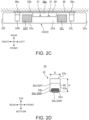
- FIGS. 2A, 2B , 2C, and 2D are a front view, a rear view, a bottom view, and a side view of the electronic apparatus 10, respectively.
- FIG. 2D illustrates the left side view of the electronic apparatus 10, while the right-side view is symmetrical to the left-side view.
- the electronic apparatus 10 has a chassis 22.
- the electronic apparatus 10 and the elements thereof are described by referring to the direction of the height of the chassis 22 as the top and bottom, the direction of the width of the chassis 22 as the left and right, and the direction of the depth of the chassis 22 as the front and back, with reference to the direction of the front view illustrated in FIG. 2A .
- the chassis 22 is a substantially rectangular parallelepiped box body with a horizontal bar shape. Specifically, the front surface 22a and the rear surface 22b of the chassis 22 each have a horizontally-long width dimension W and a height dimension H, which is smaller than the width dimension W.
- the upper surface 22c and the lower surface 22d of the chassis 22 each have a horizontally-long width dimension W and a depth dimension D, which is smaller than the width dimension W and narrower in the front-back direction.
- the left side surface 22e and the right side surface 22f of the chassis 22 each have a narrow depth dimension D in the front-back direction and a vertical height dimension H slightly larger than the depth dimension D.
- a camera 24, a microphone 25, and a light 26 are provided on the front surface 22a.
- the camera 24 is a camera device for capturing images of a user located on the front side of the electronic apparatus 10.
- the camera 24 is placed in the upper part of the front surface 22a, roughly in the center of the left and right sides thereof.
- a reference numeral 24a in FIG. 2a indicates a sliding shutter capable of physically shielding the camera 24.
- the microphone 25 is a microphone device that collects the voice and other sounds of the user of the electronic apparatus 10.
- the microphone 25 faces the front surface 22a through a plurality of microphone holes arranged in the horizontal direction below the camera 24.
- the light 26 is a light notification portion for notifying the user of the operating state of the electronic apparatus 10 and the sound collection state of the microphone 25 or the like, and is also called a smart light.
- the light 26 faces the front surface 2a through a horizontally-long narrow light-transmitting window provided between the camera 24 and the microphone 25.
- On the front surface 22a there is also provided a power light or the like of the electronic apparatus 10.
- a pair of left and right rear air intake ports 27L and 27R and a cover plate 28 are provided on the rear surface 22b.
- the rear air intake ports 27L and 27R are openings that communicate the inside and outside of the chassis 22.
- the rear air intake ports 27L and 27R have, for example, a mesh structure with a large number of holes or a structure with a plurality of slits arranged in parallel.
- the rear air intake port 27L is provided on the left side and the rear air intake port 27R is provided on the right side, relative to the horizontal center of the rear surface 22b.
- the cover plate 28 is a removable plate for hiding a concave portion 28a formed at the left-to-right center of the rear surface 22b as illustrated in FIG. 2C .
- a connection terminal portion 30 is arranged (see FIG. 3 ).
- the connection terminal portion 30 is an external terminal group to which a connector 30a is connected to connect the electronic apparatus 10 to the touch panel operation unit 12, the external display 14, the personal computer 16, and the Internet 18 or the like.
- the cables 30b and connectors 30a from these external devices are housed in the concave portion 28a and hidden by the cover plate 28.
- the reference numeral 31 in FIG. 3 is a pedestal on which a cable tie band is hooked for bundling the cables 30b.
- a power cable for connecting the electronic apparatus 10 to an external power supply is connected to the connection terminal portion 30.
- the upper surface 22c has an outline substantially identical to the outline of the lower surface 22d, but is formed of a flat plate.
- Bottom air intake ports 32L and 32R are openings that communicate the inside and outside of the chassis 22.
- the bottom air intake ports 32L and 32R may have a mesh or slit structure similar to that of the rear air intake ports 27L and 27R.
- the bottom air intake port 32L is provided at substantially the same position as the rear air intake port 27L
- the bottom air intake port 32R is provided at substantially the same position as the rear air intake port 27R (see also FIG. 8 ).
- the rubber feet 33L and 33R are legs for using the electronic apparatus 10 placed on a table or the like.
- the rubber feet 33L and 33R are placed to straddle the left and right bottom air intake ports 32L and 32R, and are fixed at positions somewhat closer to the center of the lower surface 22d than the left and right ends of the lower surface 22d.
- the rubber feet 33L and 33R are required to prevent the bottom air intake ports 32L and 32R from being blocked when the electronic apparatus 10 is placed on a table or the like.
- the rubber feet 33L and 33R need to be high enough to secure the air passage to the bottom air intake ports 32L and 32R.
- the height of the rubber feet 33L and 33R is, for example, about 5 mm.
- a side exhaust port 34L is provided on the left side surface 22e.
- the side exhaust port 34L is an opening that communicates the inside and outside of the chassis 22.
- the side exhaust port 34L may have a mesh or slit structure similar to that of the rear air intake ports 27L and 27R.
- the side exhaust port 34L is provided at the lowermost part of the left side surface 22e.
- the right side surface 22f is symmetrical to the left side surface 22e illustrated in FIG. 2D and is provided with a side exhaust port 34R (see FIG. 3 ) .
- the electronic apparatus 10 is able to be mounted on a wall of a conference room or the like without using the rubber feet 33L and 33R.
- the electronic apparatus 10 is used after attaching a bracket plate 36 to the rear surface 22b, as illustrated in FIG. 2C .
- the bracket plate 36 is a metal plate long in the horizontal direction, and the connecting plates 36a and 36b protruding from the left and right surfaces are fixed to the rear surface 22b with screws or the like.
- the connecting plates 36a and 36b are connected to cooling devices 40L and 40R and to speaker devices 42L and 42R described later in overlapping positions with reference to the horizontal direction of the chassis 22 (see FIG. 3 ). This allows the electronic apparatus 10 to be easily installed on a wall by fixing the bracket plate 36 to the wall with screws or the like.
- FIG. 3 is a plan view schematically illustrating the internal structure of the electronic apparatus 10.
- FIG. 3 is a top view of the inside of the chassis 22 with the plate forming the upper surface 22c of the chassis 22 removed.
- the electronic apparatus 10 houses a substrate 38, a pair of left and right cooling devices 40L and 40R, and a pair of left and right speaker devices 42L and 42R inside the chassis 22.
- the substrate 38 is a motherboard of the electronic apparatus 10.
- various electronic components such as a memory, a solid state drive (SSD), and the like are mounted on the substrate 38.
- the processing device 38a is, for example, a central processing unit (CPU).
- a bracket 44 is fixed to the inside of the chassis 22 with screws or the like.
- the substrate 38 is fixed to the bracket 44, which supports the substrate 38 in the chassis 22.
- the bracket 44 is a metal plate having a horizontal bracket 44a and a vertical bracket 44b, and is configured substantially in a T-shape.
- the horizontal bracket 44a is a plate-like member that is placed horizontally along a bottom surface 22g in the chassis 22.
- the vertical bracket 44b is a plate-like member that rises upward from the upper surface of the horizontal bracket 44a and is placed vertically along the front surface 22a and the rear surface 22b.
- the substrate 38 is fixed to the back surface of the vertical bracket 44b by screws or the like. This allows the substrate 38 to be placed vertically along a downward direction in the chassis 22 (see also FIG. 4 ). In other words, the substrate 38 is installed with its plane directions along the vertical and horizontal directions and its thickness direction along the front-back direction.
- the fore surface of the substrate 38 serves as the attachment surface for the bracket 44, and the back surface of the substrate 38 serves as the mounting surface for the processing device 38a and the like.
- a sub card 38b is connected to the mounting surface of the substrate 38 at a predetermined distance.
- the sub card 38b is also supported by the vertical bracket 44b and placed vertically in the chassis 22.
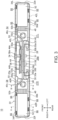
- FIG. 4 is a schematic cross section along line IV-IV in FIG. 3 .
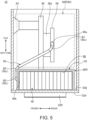
- FIG. 5 is a schematic cross section along line V-V in FIG. 3 .
- FIGS. 4 and 5 each illustrate the configuration of the right-side cooling device 40R and its surroundings illustrated in FIG. 3 .
- the bracket 44, the sub card 38b, and the like are not illustrated in FIGS. 4 and 5 .
- FIG. 6 is a schematic front cross sectional view of the right-side cooling device 40R and its surroundings illustrated in FIG. 3 .
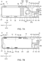
- FIG. 7A is a schematic enlarged view of the right-side cooling device 40R and its surroundings illustrated in FIG. 3 .
- the bracket 44 and other parts are not illustrated in FIG. 6 .
- the cooling devices 40L and 40R are symmetrical, and the speaker devices 42L and 42R are similarly symmetrical. Therefore, the following typically describes the right-side cooling device 40R and speaker device 42R, and omits detailed descriptions of the left-side cooling device 40L and speaker device 42L.
- the cooling devices 40L and 40R cool the processing device 38a and other electronic components mounted on the substrate 38.
- the cooling device 40R has a fan 46, a fin 48, a heat pipe 50, and a duct part 52.
- the fan 46 has a fan chassis 46a, a rotating shaft portion 46b and an impeller 46c housed in the fan chassis 46a.
- the fan 46 is a centrifugal fan in which the impeller 46c provided on the outer peripheral side rotates by the rotation of the rotating shaft portion 46b caused by a motor.
- the fan 46 is placed horizontally in the chassis 22, with the axis of rotation of the impeller 46c, in other words, the axis direction of the rotating shaft portion 46b, aligned with the vertical direction of the chassis 22. More specifically, the fan 46 is fixed to the lower surface of the horizontal bracket 44a of the bracket 44, and is placed horizontally along the bottom surface 22g of the chassis 22, with only a small gap formed between the fan 46 and the bottom surface 22g.
- the fan 46 may be placed on the bottom surface 22g.
- the fan 46 has an upper air intake port 54, a lower air intake port 55, and an exhaust port 56.
- the upper air intake port 54 is an opening formed in the upper surface of the fan chassis 46a.
- the lower air intake port 55 is an opening formed in the lower surface of the fan chassis 46a.
- the air intake ports 54 and 55 are through holes that are, for example, circular, doughnut-shaped, or have a shape with a plurality of ellipses arranged in a circumferential direction.
- the upper air intake port 54 overlaps the rear air intake port 27R in the horizontal direction, and air is mainly drawn through the rear air intake port 27R.
- the lower air intake port 55 is opposite to the bottom air intake port 32R and air is mainly drawn through the bottom air intake port 32R.
- the exhaust port 56 is an opening formed in the side surface of the fan chassis 46a facing the opposite side of the substrate 38 in the horizontal direction. In other words, the exhaust port 56 is formed in the right side surface of the fan chassis 46a for the cooling device 46R and formed in the left side surface of the fan chassis 46a for the cooling device 46L.
- the fin 48 is a heat sink made of a plurality of thin metal plates arranged at equal intervals.
- the fin 48 is placed facing the exhaust port 56 of the fan 46.
- the fin 48 faces the right side surface of the fan chassis 46a for the cooling device 46R and faces the left side surface of the fan chassis 46a for the cooling device 46L.
- the metal plates constituting the fin 48 are erected in the vertical direction and extended in the horizontal direction, so as to be parallel to each other in the front-back direction. This forms a gap between adjacent metal plates through which air from the fan 46 passes.
- the heat pipe 50 is a pipe-type heat transport device.
- the heat pipe 50 is made of a metal pipe that is flattened and formed into an oval cross section, and the working fluid is sealed in a sealed space inside.
- a first end 50a of the heat pipe 50 is connected to the processing device 38a via a heat receiving plate 58, and a second end 50b is connected to the fin 48.
- the heat receiving plate 58 is formed of a metal with high thermal conductivity such as copper or aluminum. The heat receiving plate 58 is used to bring the processing device 38a or the like and the heat pipe 50 into close contact with each other without any gap, so as to increase the heat transfer efficiency.
- the substrate 38 is placed vertically, and the fin 48 is placed horizontally along with the fan 46 so as to be close to the bottom surface 22g.
- the processing device 38a is placed above the fin 48 in the vertical direction of the chassis 22.
- the processing device 38a and the heat receiving plate 58 are located substantially in the center of the chassis 22 in the front-back direction.
- the fin 48 extends substantially over the entire length of the inside dimension of the chassis 22 in the front-back direction to maximize the heat dissipation area of the fin 48.
- the first end 50a of the heat pipe 50 is fitted into a groove formed in the back surface of the heat receiving plate 58, and is practically connected to the side end surface of the heat receiving plate 58.
- the second end 50b is connected to the front end surface of the fin 48.
- the positional relationship between the first end 50a and the second end 50b of the heat pipe 50 is out of alignment in the vertical, horizontal, and front-back directions. Therefore, the heat pipe 50 has a bending portion 50c three-dimensionally curved in the vertical, horizontal, and front-back directions between the ends 50a and 50b.
- the bending portion 50c in this embodiment has a first bending portion B1, a second bending portion B2, and a third bending portion B3, in order from the first end 50a to the second end 50b.
- the bending direction at the bending portion 50c is described below by illustrating how the extension direction of the heat pipe 50, that is, the axis direction of the pipes constituting the heat pipe 50, varies in the vertical, horizontal, front-back directions of the chassis 22.
- the following description is an example of the bending direction of the heat pipe 50 of the right-side cooling device 50R.
- the bending direction of the heat pipe 50 of the left-side cooling device 50L is left-right reversed to the bending direction of the heat pipe 50 of the right-side cooling device 50R.
- the first end 50a is connected to the right side end surface of the heat receiving plate 58 placed vertically and extends along the horizontal direction.
- the first bending portion B1 is curved in the direction from the first end 50a to the second end 50b (hereinafter, referred to as "first direction") so as to be gradually twisted to the right, forward, and downward at the same time.
- the second bending portion B2 is curved in the first direction, gradually twisting to the right and down at the same time.
- the third bending portion B3 is curved in the first direction so as to be gradually twisted to the right, backward, and downward at the same time.
- the second end 50b extends shortly in the front-back direction and is connected to the front side surface of the fin 48 placed horizontally.
- the bending direction of the bending portion 50c is not limited to the bending direction with the bending portions B1 to B3 described above.
- the bending direction of the bending portion 50c may be changed to each direction on the basis of the positional relationship between the heat receiving plate 58 and the fin 48 and the positional relationship with other parts.
- the number of bends in the bending portion 50c may be other than 3.
- the bending portion 50c is not bent at a right angle, for example, in order to avoid the collapse of the sealed space inside the heat pipe 50. It is also preferable to make the entire length of the heat pipe 50 as short as possible.
- the configuration with the bending portions B1 to B3 described above is preferable.
- the duct part 52 forms an air duct for directing air having passed through the fin 48 from the exhaust port 56 of the fan 46 to the side exhaust port 34R.
- the duct part 52 is a plastic or metal part.
- the duct part 52 includes a substantially U-shaped plate with three sides perpendicular to each other, for example.
- the height of the duct formed by the duct part 52 is the same as or slightly higher than the height of the fin 48.
- the front-to-back width of the duct formed by the duct part 52 is the same as or slightly wider than the front-to-back width of the fin 48.
- the duct part 52 may be formed of a square tube with a rectangular cross section.
- the bottom surface 22g of the flat chassis 22 serves as a bottom wall of the duct formed by the duct part 52, and therefore the duct part 52 has an approximate U-shape without a bottom plate.
- FIG. 7B illustrates a state where a speaker device 42R is installed above the right-side cooling device 40R illustrated in FIG. 7A .
- FIG. 8 is an exploded perspective view of the right-side speaker device 42R just before being attached to the chassis 22.
- the speaker devices 42L and 42R are devices that output sound to the outside of the chassis 22. Specifically, the speaker devices 42L and 42R emit sound through a saran net 60 provided on the outer surface of the chassis 22 (see FIGS 2A to 2D ).
- the saran net 60 is a net member that allows the sound from the speaker devices 42L and 42R to pass through to the outside of the chassis 22.
- a large number of holes provided in the chassis 22 may be substituted for the saran net 60.
- the saran net 60 is provided, for example, on the substantially lower half of the front surface 22a and side surfaces 22e and 22f of the chassis 22, and on the substantially lower half of the left and right ends of the rear surface 22b.
- the speaker device 42R has a speaker unit 62 and a speaker box 64.
- the speaker unit 62 is a part that actually outputs sound.
- the speaker unit 62 is, for example, a combination of a diaphragm, a magnet, and a voice coil, and may be the same as or similar to a known speaker unit.
- the speaker box 64 is a box body in which a cavity is formed to serve as a back chamber of the speaker unit 62, and is also referred to as an enclosure.
- the speaker unit 62 is attached to the fore surface of the speaker box 64.
- the speaker box 64 is installed above the fan 46, the fin 48, and the duct part 52 in such a way as to cover them.
- the speaker box 64 has the front-to-back and left-to-right widths large enough to cover the substantially entire fan 46, fin 48, and duct part 52. This allows the speaker box 64 to securely have a volume as large as possible within the chassis 22.
- a pair of mounting rods 64a and 64a are fixed to the fore surface and to the back surface of the speaker box 64.
- the mounting rods 64a are strip-shaped support members for supporting the speaker device 42R in the chassis 22.
- the mounting rod 64a needs to be able to prevent the transmission of vibration of the speaker device 42R to the chassis 22, and is made of rubber, for example.
- the mounting rod 64a is inserted into a pocket portion 66 formed along the upward direction on the inner surface of the chassis 22, and its lower surface is supported by the bottom surface 22g.
- the speaker box 64 has a predetermined gap between the inner surface of the chassis 22 and the fan 46, the fin 48, and the duct part 52. In other words, the speaker box 64 is elastically supported in the chassis 22 in a practically floating state.
- the lower surface of the speaker box 64 is provided with a relief portion 64b whose lower surface is concave above the other portions.
- the relief portion 64b is provided just above the fan 46 and is offset one step above the duct part 52.
- the relief portion 64b is intended to avoid blocking the upper air intake port 54 of the fan 46 while minimizing the reduction of the volume of the speaker box 64.
- the cooling devices 40L and 40R thus configured absorb heat from the processing device 38a and the like mounted on the substrate 38 by the heat pipe 50 via the heat receiving plate 58.
- the left and right cooling devices 40L and 40R share one heat receiving plate 58 (see FIG. 3 ).
- One heat receiving plate 58 may be installed exclusively for each of the cooling devices 40L and 40R.
- the heat transferred from the heat receiving plate 58 to the heat pipe 50 is efficiently transported by the heat pipe 50 to the fin 48 and transferred to the fin 48.
- the heat transferred to the fin 48 is efficiently dissipated by receiving air from the exhaust port 56 of the fan 46.
- the high-temperature exhaust gas that has passed through the fin 48 passes through an air duct formed by the duct part 52 and the bottom surface 22g of the chassis 22, and is discharged to the outside of the chassis 22 through the side exhaust ports 34L and 34R.
- the arrows illustrated in FIGS. 4 and 6 with one-dotted lines schematically represent the flows of air drawn by the fan 46 and air discharged by the fan 46.
- the fan 46 draws air from the outside of the chassis 22 through the bottom air intake ports 32L and 32R and from the lower air intake port 55.
- the fan 46 draws air from the outside of the chassis 22 through the rear air intake ports 27L and 27R and from the upper air intake port 54.
- the speaker box 64 has a relief portion 64b on the lower surface just above the fan 46 (see FIG. 6 ). Therefore, the air is smoothly drawn through the rear air intake ports 27L and 27R to the upper air intake port 54.
- the electronic apparatus 10 of this embodiment includes the chassis 22, the substrate 38 on which the processing device 38a is mounted, the speaker devices 42L and 42R, and the cooling devices 40L and 40R that cool the processing device 38a.
- the substrate 38 is placed vertically along the vertical direction of the chassis 22.
- the cooling devices 40L and 40R have the fan 46 and the fin 48 placed horizontally in the chassis 22, and the heat pipe 50 that connects the processing device 38a and the fin 48. Note that only one of the cooling devices 40L and 40R may be provided. Similarly, only one of the speaker devices 42L and 42R may be provided.
- the electronic apparatus 10 houses the substrate 38, the speaker devices 42L and 42R, and the cooling devices 40L and 40R in the chassis 22.
- the electronic apparatus 10 has the substrate 38 that is placed vertically and has the fan 46 and the fin 48 that are placed horizontally, wherein the processing device 38a mounted on the substrate 38 is connected to the fin 48 by the heat pipe 50.
- This allows the electronic apparatus 10 to minimize the depth dimension D of the chassis 22 by vertically placing the substrate 38, which requires a large surface area to avoid the influence of the substrate 38 on the depth dimension D of the chassis 22.
- the depth dimension D of the electronic apparatus 10 of this embodiment is 90 mm or less.
- the fan 46 and fin 48 of the electronic apparatus 10 are placed horizontally. Therefore, a large space is secured above the fan 46 and the fin 48, and the installation space for the speaker box 64 is secured here, which contributes to the increase in the volume of the speaker box 64.
- the processing device 38a is placed above the fin 48.
- the heat pipe 50 connects the processing device 38a to the fin 48. That is, the heat pipe 50 has the bending portion 50c, which is curved in the vertical, horizontal, and front-back directions of the chassis 22, between the first end 50a and the second end 50b. This allows the heat pipe 50 to securely connect the processing device 38a and the fin 48, which are in different positions in the vertical, horizontal, and front-back directions, in the chassis 22 having a narrow depth dimension D.
- the heat pipe 50 has the three-dimensional bending portion 50c, which prevents the pipe from being forcibly bent and the sealed space inside the pipe from being blocked, which reduces the heat transfer performance.
- the cooling devices 40L and 40R have the duct part 52 that is placed facing the fin 48 under the speaker box 64 to distribute air, which has left the exhaust port 56 of the fan 46 and has passed through the fin 48, to the outside of the chassis 22. This prevents the air that has discharged from the fan 46 from leaking into the chassis 22 and reducing the air volume. This also reduces the so-called air noise and its influence on the microphone 25.
- the duct part 52 may be omitted if, for example, the speaker box 64 is able to be used instead.
- the electronic apparatus 10 of this embodiment also includes the chassis 22, the substrate 38 on which the processing device 38a is mounted, the speaker devices 42L and 42R, and the cooling devices 40L and 40R that cool the processing device 38a.
- the cooling devices 40L and 40R have the fan 46 with the rotating shaft portion 46b of the impeller 46c placed along the vertical direction of the chassis 22, the fin 48, the heat pipe 50 that connects the processing device 38a to the fin 48, and the duct part 52.
- the duct part 52 is placed facing the fin 48 under the speaker box 64, and forms an air duct that distributes the air that has left the exhaust port 56 of the fan 46 and has passed through the fin 48 to the outside of the chassis 22.
- the electronic apparatus 10 is provided with the exhaust port 56 on the side surface of the fan 46, with the fin 48 and the duct part 52 placed on the side of the exhaust port 56, and with the speaker box 64 placed thereabove.
- the parts of the cooling devices 40L and 40R are placed along the horizontal direction of the chassis 22, and the speaker box 64 is placed thereabove.
- the electronic apparatus 10 is able to efficiently house the parts within the chassis 22 while minimizing the depth dimension D of the chassis 22.
- the electronic apparatus 10 of this embodiment includes a pair of speaker devices 42L and 42R and a pair of cooling devices 40L and 40R, by which good sound quality and high cooling performance are obtained.
- the speaker devices 42L and 42R and the cooling devices 40L and 40R are placed on the left and right sides of the substrate 38 in the center, respectively, and therefore there is no need to increase the depth dimension D of the chassis 22.
- the electronic apparatus 10 has a good weight balance since the speaker devices 42L and 42R and the cooling devices 40L and 40R are placed equally on the left and right sides of the substrate 38 in the center.
- the electronic apparatus 10 is provided with a concave portion 28a on the rear surface 22b on the back side of the substrate 38, where there are not placed the speaker devices 42L and 42R and the cooling devices 40L and 40R and where a space is relatively easy to secure in the chassis 22, and the connection terminal portion 30 is provided here. Therefore, as illustrated in FIG. 2C , the practical depth dimension of the electronic apparatus 10 does not increase due to the connector 30a and cable 30b connected to the connection terminal portion 30 when the electronic apparatus 10 is fixed by wall-hanging.
- the bracket plate 36 for fixing the electronic apparatus 10 by wall-hanging has the connecting plates 36a and 36b that are connected in the positions overlapping the cooling devices 40L and 40R and the speaker devices 42L and 42R with reference to the horizontal direction of the chassis 22. Therefore, the chassis 22 is able to directly bear the weights of the cooling devices 40L and 40R and the speaker devices 42L and 42R, which are heavier than the substrate 38, on the bracket plate 36. Therefore, in the case where the electronic apparatus 10 is fixed on the wall, the left and right sides of the chassis 22 are able to be suppressed from warping due to the weights of the cooling devices 40L and 40R and the speaker devices 42L and 42R.
- the present invention is not limited to the embodiments described above, and naturally may be freely modified to the extent not to depart from the gist of the present invention.
Landscapes
- Engineering & Computer Science (AREA)
- Microelectronics & Electronic Packaging (AREA)
- Physics & Mathematics (AREA)
- Thermal Sciences (AREA)
- Theoretical Computer Science (AREA)
- General Engineering & Computer Science (AREA)
- Human Computer Interaction (AREA)
- General Physics & Mathematics (AREA)
- Signal Processing (AREA)
- Acoustics & Sound (AREA)
- Computer Hardware Design (AREA)
- Power Engineering (AREA)
- Cooling Or The Like Of Electrical Apparatus (AREA)
Abstract
Description
- The present invention relates to an electronic apparatus available as a terminal device for teleconferencing.
- Currently, there are used electronic apparatuses that allow remote conferences and calls via audio and video by using the Internet, telephone lines, or the like. This type of electronic apparatus is equipped with a speaker device for outputting audio and other sounds from the other party (for example, refer to
Japanese Unexamined Patent Application Publication No. 2020-178244 - In recent years, a demand for online conferencing using displays has been increasing. For this reason, there is a request for using the above-mentioned electronic apparatus on a wall above or below a large wall-mounted display, for example. In this case, the electronic apparatus is required to minimize the depth dimension of a chassis to reduce the protrusion length from the wall.
- In addition to a speaker device, however, this type of electronic apparatus may contain a substrate with a processing device for control, a cooling device for cooling the processing device, and the like, and these parts need to be housed in the chassis within the depth dimension limitations. Naturally, it is also desirable for this type of electronic apparatus to have a small depth dimension in the case where it is placed on a desk or the like.
- The present invention has been made in consideration of the above problem of the conventional techniques, and it is an object of the present invention to provide an electronic apparatus capable of reducing the depth dimension of the chassis while housing a plurality of parts.
- An electronic apparatus according to the first aspect of the present invention includes: a chassis; a substrate housed in the chassis and with a processing device mounted thereon; a speaker device housed in the chassis and having a speaker unit and a speaker box; and a cooling device housed in the chassis and used to cool the processing device, wherein the substrate is placed vertically along the vertical direction of the chassis, and wherein the cooling device includes: a fan having air intake ports provided on upper and lower surfaces, exhaust ports provided on side surfaces, and an impeller, and being placed horizontally in the chassis with a rotating shaft of the impeller placed along the vertical direction of the chassis; a fin placed facing the exhaust port of the fan and placed horizontally in the chassis; and a heat pipe with a first end connected to the processing device and a second end connected to the fin. This allows the electronic apparatus to minimize the depth dimension of the chassis by placing the substrate vertically and the fan and the fin horizontally, while housing the substrate, the speaker device, and the cooling device inside the chassis.
- An electronic apparatus according to the second aspect of the present invention includes: a chassis; a substrate housed in the chassis and with a processing device mounted thereon; a speaker device housed in the chassis and having a speaker unit and a speaker box; and a cooling device housed in the chassis and used to cool the processing device, wherein the cooling device includes: a fan having air intake ports provided on upper and lower surfaces, exhaust ports provided on side surfaces, and an impeller, with a rotating shaft of the impeller placed along the vertical direction of the chassis; a fin placed facing the exhaust port of the fan; a heat pipe with a first end connected to the processing device and a second end connected to the fin; and a duct part placed facing the fin under the speaker box and used to distribute air having left the exhaust port and passed through the fin to the outside of the chassis. This allows the electronic apparatus to efficiently house the parts in the chassis while minimizing the depth dimension D of the chassis, since the parts of the cooling device are placed along the horizontal direction of the chassis and the speaker box is placed thereabove.
- According to the above-described aspects of the present invention, it is an object of the present invention to provide an electronic apparatus capable of reducing the depth dimension of the chassis while housing a plurality of parts.
-
-
FIG. 1 is a system diagram illustrating one mode of using an electronic apparatus according to one embodiment. -
FIG. 2A is a front view of the electronic apparatus. -
FIG. 2B is a rear view of the electronic apparatus. -
FIG. 2C is a bottom view of the electronic apparatus. -
FIG. 2D is a side view of the electronic apparatus. -
FIG. 3 is a plan view schematically illustrating the internal structure of the electronic apparatus. -
FIG. 4 is a schematic cross section along line IV-IV inFIG. 3 . -
FIG. 5 is a schematic cross section along line V-V inFIG. 3 . -
FIG. 6 is a schematic front cross-sectional view of a right-side cooling device and its surroundings illustrated inFIG. 3 . -
FIG. 7A is a schematic enlarged view of the right-side cooling device and its surroundings illustrated inFIG. 3 . -
FIG. 7B is a diagram illustrating a state where a speaker device is installed above the right-side cooling device illustrated inFIG. 7A . -
FIG. 8 is an exploded perspective view of the right-side speaker device just before being attached to the chassis. - An electronic apparatus according to the present invention will be described in detail below with reference to the accompanying drawings, by giving preferable embodiments.
-
FIG. 1 is a system diagram illustrating one mode of using anelectronic apparatus 10 according to one embodiment. Theelectronic apparatus 10 of this embodiment is a terminal device capable of being used, for example, in an online conference system for conducting conferences and calls using audio and video between remote locations connected via the Internet. - The online conference system illustrated in
FIG. 1 includes anelectronic apparatus 10 according to this embodiment, a touchpanel operation unit 12, anexternal display 14, and apersonal computer 16. As illustrated inFIG. 1 , theelectronic apparatus 10 is fixed on a wall above or below theexternal display 14, which is fixed on the wall in a conference room, for example. Theelectronic apparatus 10 is also able to be placed on a table or the like when it is used. - The touch
panel operation unit 12 is a touch panel terminal for input operation to theelectronic apparatus 10. Theexternal display 14 is able to display, for example, information from thepersonal computer 20 of the other party of the conference connected to theelectronic apparatus 10 via the Internet 18 and thecloud server 19. Specifically, theexternal display 14 displays the face images and documents of the other party of the conference under the control of theelectronic apparatus 10. Thepersonal computer 16 is able to transmit, for example, documents or the like from a user of theelectronic apparatus 10 to theexternal display 14 and the other party'spersonal computer 20. Thepersonal computer 16 may be used for input operation to theelectronic apparatus 10 instead of the touchpanel operation unit 12. - The
electronic apparatus 10 is connected to the touchpanel operation unit 12, theexternal display 14, and thepersonal computer 16 by using connectors and cables conforming to prescribed connection standards, such as, for example, USB and HDMI (registered trademark) standards. - First, the external structure of the
electronic apparatus 10 is described. -
FIGS. 2A, 2B ,2C, and 2D are a front view, a rear view, a bottom view, and a side view of theelectronic apparatus 10, respectively.FIG. 2D illustrates the left side view of theelectronic apparatus 10, while the right-side view is symmetrical to the left-side view. - As illustrated in
FIGS. 2A to 2D , theelectronic apparatus 10 has achassis 22. Hereinafter, theelectronic apparatus 10 and the elements thereof are described by referring to the direction of the height of thechassis 22 as the top and bottom, the direction of the width of thechassis 22 as the left and right, and the direction of the depth of thechassis 22 as the front and back, with reference to the direction of the front view illustrated inFIG. 2A . - The
chassis 22 is a substantially rectangular parallelepiped box body with a horizontal bar shape. Specifically, thefront surface 22a and therear surface 22b of thechassis 22 each have a horizontally-long width dimension W and a height dimension H, which is smaller than the width dimension W. Theupper surface 22c and thelower surface 22d of thechassis 22 each have a horizontally-long width dimension W and a depth dimension D, which is smaller than the width dimension W and narrower in the front-back direction. Theleft side surface 22e and theright side surface 22f of thechassis 22 each have a narrow depth dimension D in the front-back direction and a vertical height dimension H slightly larger than the depth dimension D. - As illustrated in
FIG. 2A , acamera 24, amicrophone 25, and alight 26 are provided on thefront surface 22a. - The
camera 24 is a camera device for capturing images of a user located on the front side of theelectronic apparatus 10. Thecamera 24 is placed in the upper part of thefront surface 22a, roughly in the center of the left and right sides thereof. Areference numeral 24a inFIG. 2a indicates a sliding shutter capable of physically shielding thecamera 24. Themicrophone 25 is a microphone device that collects the voice and other sounds of the user of theelectronic apparatus 10. Themicrophone 25 faces thefront surface 22a through a plurality of microphone holes arranged in the horizontal direction below thecamera 24. The light 26 is a light notification portion for notifying the user of the operating state of theelectronic apparatus 10 and the sound collection state of themicrophone 25 or the like, and is also called a smart light. The light 26 faces the front surface 2a through a horizontally-long narrow light-transmitting window provided between thecamera 24 and themicrophone 25. On thefront surface 22a, there is also provided a power light or the like of theelectronic apparatus 10. - As illustrated in
FIG. 2B , on therear surface 22b, there are provided a pair of left and right rearair intake ports cover plate 28. - The rear
air intake ports chassis 22. The rearair intake ports air intake port 27L is provided on the left side and the rearair intake port 27R is provided on the right side, relative to the horizontal center of therear surface 22b. - The
cover plate 28 is a removable plate for hiding aconcave portion 28a formed at the left-to-right center of therear surface 22b as illustrated inFIG. 2C . In theconcave portion 28a, aconnection terminal portion 30 is arranged (seeFIG. 3 ). Theconnection terminal portion 30 is an external terminal group to which aconnector 30a is connected to connect theelectronic apparatus 10 to the touchpanel operation unit 12, theexternal display 14, thepersonal computer 16, and theInternet 18 or the like. Thecables 30b andconnectors 30a from these external devices are housed in theconcave portion 28a and hidden by thecover plate 28. Thereference numeral 31 inFIG. 3 is a pedestal on which a cable tie band is hooked for bundling thecables 30b. In addition, a power cable for connecting theelectronic apparatus 10 to an external power supply is connected to theconnection terminal portion 30. - As illustrated in
FIG. 2C , there are provided a pair of left and right bottomair intake ports right rubber feet lower surface 22d. Theupper surface 22c has an outline substantially identical to the outline of thelower surface 22d, but is formed of a flat plate. - Bottom
air intake ports chassis 22. The bottomair intake ports air intake ports chassis 22, the bottomair intake port 32L is provided at substantially the same position as the rearair intake port 27L, and the bottomair intake port 32R is provided at substantially the same position as the rearair intake port 27R (see alsoFIG. 8 ). - The
rubber feet electronic apparatus 10 placed on a table or the like. Therubber feet air intake ports lower surface 22d than the left and right ends of thelower surface 22d. Therubber feet air intake ports electronic apparatus 10 is placed on a table or the like. In other words, therubber feet air intake ports rubber feet - As illustrated in
FIG. 2D , aside exhaust port 34L is provided on theleft side surface 22e. - The
side exhaust port 34L is an opening that communicates the inside and outside of thechassis 22. Theside exhaust port 34L may have a mesh or slit structure similar to that of the rearair intake ports side exhaust port 34L is provided at the lowermost part of theleft side surface 22e. Theright side surface 22f is symmetrical to theleft side surface 22e illustrated inFIG. 2D and is provided with aside exhaust port 34R (seeFIG. 3 ) . - As described above, the
electronic apparatus 10 is able to be mounted on a wall of a conference room or the like without using therubber feet electronic apparatus 10 is used after attaching abracket plate 36 to therear surface 22b, as illustrated inFIG. 2C . Thebracket plate 36 is a metal plate long in the horizontal direction, and the connectingplates rear surface 22b with screws or the like. The connectingplates devices speaker devices FIG. 3 ). This allows theelectronic apparatus 10 to be easily installed on a wall by fixing thebracket plate 36 to the wall with screws or the like. - The internal structure of the
electronic apparatus 10 is then described. -
FIG. 3 is a plan view schematically illustrating the internal structure of theelectronic apparatus 10.FIG. 3 is a top view of the inside of thechassis 22 with the plate forming theupper surface 22c of thechassis 22 removed. - As illustrated in
FIG. 3 , theelectronic apparatus 10 houses asubstrate 38, a pair of left andright cooling devices right speaker devices chassis 22. - The
substrate 38 is a motherboard of theelectronic apparatus 10. In addition to aprocessing device 38a, various electronic components such as a memory, a solid state drive (SSD), and the like are mounted on thesubstrate 38. Theprocessing device 38a is, for example, a central processing unit (CPU). - A
bracket 44 is fixed to the inside of thechassis 22 with screws or the like. Thesubstrate 38 is fixed to thebracket 44, which supports thesubstrate 38 in thechassis 22. Thebracket 44 is a metal plate having ahorizontal bracket 44a and avertical bracket 44b, and is configured substantially in a T-shape. Thehorizontal bracket 44a is a plate-like member that is placed horizontally along abottom surface 22g in thechassis 22. Thevertical bracket 44b is a plate-like member that rises upward from the upper surface of thehorizontal bracket 44a and is placed vertically along thefront surface 22a and therear surface 22b. - The
substrate 38 is fixed to the back surface of thevertical bracket 44b by screws or the like. This allows thesubstrate 38 to be placed vertically along a downward direction in the chassis 22 (see alsoFIG. 4 ). In other words, thesubstrate 38 is installed with its plane directions along the vertical and horizontal directions and its thickness direction along the front-back direction. - The fore surface of the
substrate 38 serves as the attachment surface for thebracket 44, and the back surface of thesubstrate 38 serves as the mounting surface for theprocessing device 38a and the like. Asub card 38b is connected to the mounting surface of thesubstrate 38 at a predetermined distance. Thesub card 38b is also supported by thevertical bracket 44b and placed vertically in thechassis 22. -
FIG. 4 is a schematic cross section along line IV-IV inFIG. 3 .FIG. 5 is a schematic cross section along line V-V inFIG. 3 .FIGS. 4 and5 each illustrate the configuration of the right-side cooling device 40R and its surroundings illustrated inFIG. 3 . Thebracket 44, thesub card 38b, and the like are not illustrated inFIGS. 4 and5 .FIG. 6 is a schematic front cross sectional view of the right-side cooling device 40R and its surroundings illustrated inFIG. 3 .FIG. 7A is a schematic enlarged view of the right-side cooling device 40R and its surroundings illustrated inFIG. 3 . Thebracket 44 and other parts are not illustrated inFIG. 6 . - As illustrated in
FIG. 3 , thecooling devices speaker devices side cooling device 40R andspeaker device 42R, and omits detailed descriptions of the left-side cooling device 40L andspeaker device 42L. - The
cooling devices processing device 38a and other electronic components mounted on thesubstrate 38. - As illustrated in
FIGS. 3 to 7A , thecooling device 40R has afan 46, afin 48, aheat pipe 50, and aduct part 52. - The
fan 46 has afan chassis 46a, arotating shaft portion 46b and animpeller 46c housed in thefan chassis 46a. Thefan 46 is a centrifugal fan in which theimpeller 46c provided on the outer peripheral side rotates by the rotation of therotating shaft portion 46b caused by a motor. Thefan 46 is placed horizontally in thechassis 22, with the axis of rotation of theimpeller 46c, in other words, the axis direction of therotating shaft portion 46b, aligned with the vertical direction of thechassis 22. More specifically, thefan 46 is fixed to the lower surface of thehorizontal bracket 44a of thebracket 44, and is placed horizontally along thebottom surface 22g of thechassis 22, with only a small gap formed between thefan 46 and thebottom surface 22g. Thefan 46 may be placed on thebottom surface 22g. - The
fan 46 has an upperair intake port 54, a lowerair intake port 55, and anexhaust port 56. - The upper
air intake port 54 is an opening formed in the upper surface of thefan chassis 46a. The lowerair intake port 55 is an opening formed in the lower surface of thefan chassis 46a. Theair intake ports air intake port 54 overlaps the rearair intake port 27R in the horizontal direction, and air is mainly drawn through the rearair intake port 27R. The lowerair intake port 55 is opposite to the bottomair intake port 32R and air is mainly drawn through the bottomair intake port 32R. Theexhaust port 56 is an opening formed in the side surface of thefan chassis 46a facing the opposite side of thesubstrate 38 in the horizontal direction. In other words, theexhaust port 56 is formed in the right side surface of thefan chassis 46a for the cooling device 46R and formed in the left side surface of thefan chassis 46a for the cooling device 46L. - The
fin 48 is a heat sink made of a plurality of thin metal plates arranged at equal intervals. Thefin 48 is placed facing theexhaust port 56 of thefan 46. In other words, thefin 48 faces the right side surface of thefan chassis 46a for the cooling device 46R and faces the left side surface of thefan chassis 46a for the cooling device 46L. The metal plates constituting thefin 48 are erected in the vertical direction and extended in the horizontal direction, so as to be parallel to each other in the front-back direction. This forms a gap between adjacent metal plates through which air from thefan 46 passes. - The
heat pipe 50 is a pipe-type heat transport device. Theheat pipe 50 is made of a metal pipe that is flattened and formed into an oval cross section, and the working fluid is sealed in a sealed space inside. Afirst end 50a of theheat pipe 50 is connected to theprocessing device 38a via aheat receiving plate 58, and asecond end 50b is connected to thefin 48. Theheat receiving plate 58 is formed of a metal with high thermal conductivity such as copper or aluminum. Theheat receiving plate 58 is used to bring theprocessing device 38a or the like and theheat pipe 50 into close contact with each other without any gap, so as to increase the heat transfer efficiency. - In the
electronic apparatus 10 of this embodiment, thesubstrate 38 is placed vertically, and thefin 48 is placed horizontally along with thefan 46 so as to be close to thebottom surface 22g. In other words, theprocessing device 38a is placed above thefin 48 in the vertical direction of thechassis 22. In addition, theprocessing device 38a and theheat receiving plate 58 are located substantially in the center of thechassis 22 in the front-back direction. On the other hand, thefin 48 extends substantially over the entire length of the inside dimension of thechassis 22 in the front-back direction to maximize the heat dissipation area of thefin 48. Thefirst end 50a of theheat pipe 50 is fitted into a groove formed in the back surface of theheat receiving plate 58, and is practically connected to the side end surface of theheat receiving plate 58. Thesecond end 50b is connected to the front end surface of thefin 48. - Therefore, the positional relationship between the
first end 50a and thesecond end 50b of theheat pipe 50 is out of alignment in the vertical, horizontal, and front-back directions. Therefore, theheat pipe 50 has a bendingportion 50c three-dimensionally curved in the vertical, horizontal, and front-back directions between theends - As illustrated in
FIGS. 4 ,6 and7A , the bendingportion 50c in this embodiment has a first bending portion B1, a second bending portion B2, and a third bending portion B3, in order from thefirst end 50a to thesecond end 50b. - The bending direction at the bending
portion 50c is described below by illustrating how the extension direction of theheat pipe 50, that is, the axis direction of the pipes constituting theheat pipe 50, varies in the vertical, horizontal, front-back directions of thechassis 22. In addition, as described above, the following description is an example of the bending direction of theheat pipe 50 of the right-side cooling device 50R. The bending direction of theheat pipe 50 of the left-side cooling device 50L is left-right reversed to the bending direction of theheat pipe 50 of the right-side cooling device 50R. - The
first end 50a is connected to the right side end surface of theheat receiving plate 58 placed vertically and extends along the horizontal direction. The first bending portion B1 is curved in the direction from thefirst end 50a to thesecond end 50b (hereinafter, referred to as "first direction") so as to be gradually twisted to the right, forward, and downward at the same time. - Between the first bending portion B1 and the second bending portion B2, there is a straight-line portion going to the right in the first direction while going forward diagonally down. The second bending portion B2 is curved in the first direction, gradually twisting to the right and down at the same time.
- Between the second bending portion B2 and the third bending portion B3, there is a straight-line portion which is diagonally rightward and downward in the first direction. The third bending portion B3 is curved in the first direction so as to be gradually twisted to the right, backward, and downward at the same time. The
second end 50b extends shortly in the front-back direction and is connected to the front side surface of thefin 48 placed horizontally. - Needless to say, the bending direction of the bending
portion 50c is not limited to the bending direction with the bending portions B1 to B3 described above. In other words, the bending direction of the bendingportion 50c may be changed to each direction on the basis of the positional relationship between theheat receiving plate 58 and thefin 48 and the positional relationship with other parts. The number of bends in the bendingportion 50c may be other than 3. Preferably, however, the bendingportion 50c is not bent at a right angle, for example, in order to avoid the collapse of the sealed space inside theheat pipe 50. It is also preferable to make the entire length of theheat pipe 50 as short as possible. In this respect, in the arrangement of theheat receiving plate 58 and thefin 48 in the present embodiment, the configuration with the bending portions B1 to B3 described above is preferable. - As illustrated in
FIGS. 5 to 7A , theduct part 52 forms an air duct for directing air having passed through thefin 48 from theexhaust port 56 of thefan 46 to theside exhaust port 34R. Theduct part 52 is a plastic or metal part. Theduct part 52 includes a substantially U-shaped plate with three sides perpendicular to each other, for example. The height of the duct formed by theduct part 52 is the same as or slightly higher than the height of thefin 48. The front-to-back width of the duct formed by theduct part 52 is the same as or slightly wider than the front-to-back width of thefin 48. - The
duct part 52 may be formed of a square tube with a rectangular cross section. In this embodiment, thebottom surface 22g of theflat chassis 22 serves as a bottom wall of the duct formed by theduct part 52, and therefore theduct part 52 has an approximate U-shape without a bottom plate. -
FIG. 7B illustrates a state where aspeaker device 42R is installed above the right-side cooling device 40R illustrated inFIG. 7A .FIG. 8 is an exploded perspective view of the right-side speaker device 42R just before being attached to thechassis 22. - The
speaker devices chassis 22. Specifically, thespeaker devices saran net 60 provided on the outer surface of the chassis 22 (seeFIGS 2A to 2D ). - The
saran net 60 is a net member that allows the sound from thespeaker devices chassis 22. A large number of holes provided in thechassis 22 may be substituted for thesaran net 60. As illustrated inFIGS. 2A to 2D , in this embodiment, thesaran net 60 is provided, for example, on the substantially lower half of thefront surface 22a andside surfaces chassis 22, and on the substantially lower half of the left and right ends of therear surface 22b. - As illustrated in
FIGS. 7B and8 , thespeaker device 42R has aspeaker unit 62 and aspeaker box 64. - The
speaker unit 62 is a part that actually outputs sound. Thespeaker unit 62 is, for example, a combination of a diaphragm, a magnet, and a voice coil, and may be the same as or similar to a known speaker unit. - The
speaker box 64 is a box body in which a cavity is formed to serve as a back chamber of thespeaker unit 62, and is also referred to as an enclosure. Thespeaker unit 62 is attached to the fore surface of thespeaker box 64. As illustrated inFIGS. 7A and 7B , thespeaker box 64 is installed above thefan 46, thefin 48, and theduct part 52 in such a way as to cover them. In other words, thespeaker box 64 has the front-to-back and left-to-right widths large enough to cover the substantiallyentire fan 46,fin 48, andduct part 52. This allows thespeaker box 64 to securely have a volume as large as possible within thechassis 22. - A pair of mounting
rods speaker box 64. The mountingrods 64a are strip-shaped support members for supporting thespeaker device 42R in thechassis 22. The mountingrod 64a needs to be able to prevent the transmission of vibration of thespeaker device 42R to thechassis 22, and is made of rubber, for example. The mountingrod 64a is inserted into apocket portion 66 formed along the upward direction on the inner surface of thechassis 22, and its lower surface is supported by thebottom surface 22g. In this case, thespeaker box 64 has a predetermined gap between the inner surface of thechassis 22 and thefan 46, thefin 48, and theduct part 52. In other words, thespeaker box 64 is elastically supported in thechassis 22 in a practically floating state. - As illustrated in
FIG. 6 , the lower surface of thespeaker box 64 is provided with arelief portion 64b whose lower surface is concave above the other portions. Therelief portion 64b is provided just above thefan 46 and is offset one step above theduct part 52. Therelief portion 64b is intended to avoid blocking the upperair intake port 54 of thefan 46 while minimizing the reduction of the volume of thespeaker box 64. - The
cooling devices processing device 38a and the like mounted on thesubstrate 38 by theheat pipe 50 via theheat receiving plate 58. In this embodiment, the left andright cooling devices FIG. 3 ). Oneheat receiving plate 58 may be installed exclusively for each of thecooling devices - The heat transferred from the
heat receiving plate 58 to theheat pipe 50 is efficiently transported by theheat pipe 50 to thefin 48 and transferred to thefin 48. The heat transferred to thefin 48 is efficiently dissipated by receiving air from theexhaust port 56 of thefan 46. The high-temperature exhaust gas that has passed through thefin 48 passes through an air duct formed by theduct part 52 and thebottom surface 22g of thechassis 22, and is discharged to the outside of thechassis 22 through theside exhaust ports FIGS. 4 and6 with one-dotted lines schematically represent the flows of air drawn by thefan 46 and air discharged by thefan 46. - In this case, the
fan 46 draws air from the outside of thechassis 22 through the bottomair intake ports air intake port 55. In addition, thefan 46 draws air from the outside of thechassis 22 through the rearair intake ports air intake port 54. Although the space between the rearair intake ports air intake port 54 is mostly blocked by thespeaker box 64, air is drawn into the upperair intake port 54 through the gap around thespeaker box 64. In this case, thespeaker box 64 has arelief portion 64b on the lower surface just above the fan 46 (seeFIG. 6 ). Therefore, the air is smoothly drawn through the rearair intake ports air intake port 54. - As described above, the
electronic apparatus 10 of this embodiment includes thechassis 22, thesubstrate 38 on which theprocessing device 38a is mounted, thespeaker devices cooling devices processing device 38a. Note here that thesubstrate 38 is placed vertically along the vertical direction of thechassis 22. Thecooling devices fan 46 and thefin 48 placed horizontally in thechassis 22, and theheat pipe 50 that connects theprocessing device 38a and thefin 48. Note that only one of thecooling devices speaker devices - Thus, the
electronic apparatus 10 houses thesubstrate 38, thespeaker devices cooling devices chassis 22. Theelectronic apparatus 10, however, has thesubstrate 38 that is placed vertically and has thefan 46 and thefin 48 that are placed horizontally, wherein theprocessing device 38a mounted on thesubstrate 38 is connected to thefin 48 by theheat pipe 50. This allows theelectronic apparatus 10 to minimize the depth dimension D of thechassis 22 by vertically placing thesubstrate 38, which requires a large surface area to avoid the influence of thesubstrate 38 on the depth dimension D of thechassis 22. For example, the depth dimension D of theelectronic apparatus 10 of this embodiment is 90 mm or less. As a result, when theelectronic apparatus 10 is installed on a wall, the protrusion length from the wall is suppressed (seeFIG. 2C ). Moreover, thefan 46 andfin 48 of theelectronic apparatus 10 are placed horizontally. Therefore, a large space is secured above thefan 46 and thefin 48, and the installation space for thespeaker box 64 is secured here, which contributes to the increase in the volume of thespeaker box 64. - In the
electronic apparatus 10, theprocessing device 38a is placed above thefin 48. Theheat pipe 50 connects theprocessing device 38a to thefin 48. That is, theheat pipe 50 has the bendingportion 50c, which is curved in the vertical, horizontal, and front-back directions of thechassis 22, between thefirst end 50a and thesecond end 50b. This allows theheat pipe 50 to securely connect theprocessing device 38a and thefin 48, which are in different positions in the vertical, horizontal, and front-back directions, in thechassis 22 having a narrow depth dimension D. Moreover, theheat pipe 50 has the three-dimensional bending portion 50c, which prevents the pipe from being forcibly bent and the sealed space inside the pipe from being blocked, which reduces the heat transfer performance. - The
cooling devices duct part 52 that is placed facing thefin 48 under thespeaker box 64 to distribute air, which has left theexhaust port 56 of thefan 46 and has passed through thefin 48, to the outside of thechassis 22. This prevents the air that has discharged from thefan 46 from leaking into thechassis 22 and reducing the air volume. This also reduces the so-called air noise and its influence on themicrophone 25. Theduct part 52 may be omitted if, for example, thespeaker box 64 is able to be used instead. - The
electronic apparatus 10 of this embodiment also includes thechassis 22, thesubstrate 38 on which theprocessing device 38a is mounted, thespeaker devices cooling devices processing device 38a. Thecooling devices fan 46 with therotating shaft portion 46b of theimpeller 46c placed along the vertical direction of thechassis 22, thefin 48, theheat pipe 50 that connects theprocessing device 38a to thefin 48, and theduct part 52. Theduct part 52 is placed facing thefin 48 under thespeaker box 64, and forms an air duct that distributes the air that has left theexhaust port 56 of thefan 46 and has passed through thefin 48 to the outside of thechassis 22. - Thus, the
electronic apparatus 10 is provided with theexhaust port 56 on the side surface of thefan 46, with thefin 48 and theduct part 52 placed on the side of theexhaust port 56, and with thespeaker box 64 placed thereabove. In other words, in theelectronic apparatus 10, the parts of thecooling devices chassis 22, and thespeaker box 64 is placed thereabove. As a result, theelectronic apparatus 10 is able to efficiently house the parts within thechassis 22 while minimizing the depth dimension D of thechassis 22. - Moreover, the
electronic apparatus 10 of this embodiment includes a pair ofspeaker devices cooling devices speaker devices cooling devices substrate 38 in the center, respectively, and therefore there is no need to increase the depth dimension D of thechassis 22. In addition, theelectronic apparatus 10 has a good weight balance since thespeaker devices cooling devices substrate 38 in the center. - In this case, the
electronic apparatus 10 is provided with aconcave portion 28a on therear surface 22b on the back side of thesubstrate 38, where there are not placed thespeaker devices cooling devices chassis 22, and theconnection terminal portion 30 is provided here. Therefore, as illustrated inFIG. 2C , the practical depth dimension of theelectronic apparatus 10 does not increase due to theconnector 30a andcable 30b connected to theconnection terminal portion 30 when theelectronic apparatus 10 is fixed by wall-hanging. - Moreover, the
bracket plate 36 for fixing theelectronic apparatus 10 by wall-hanging has the connectingplates cooling devices speaker devices chassis 22. Therefore, thechassis 22 is able to directly bear the weights of thecooling devices speaker devices substrate 38, on thebracket plate 36. Therefore, in the case where theelectronic apparatus 10 is fixed on the wall, the left and right sides of thechassis 22 are able to be suppressed from warping due to the weights of thecooling devices speaker devices - The present invention is not limited to the embodiments described above, and naturally may be freely modified to the extent not to depart from the gist of the present invention.
-
- 10
- electronic apparatus
- 22
- chassis
- 27L, 27R
- rear air intake port
- 30
- connection terminal portion
- 32L, 32R
- bottom air intake port
- 34L, 34R
- side exhaust port
- 36
- bracket plate
- 38
- substrate
- 38a
- processing device
- 40L, 40R
- cooling device
- 42L, 42R
- speaker device
- 46
- fan
- 48
- fin
- 50
- heat pipe
- 50c
- bending portion
- 52
- duct part
- 62
- speaker unit
- 64
- speaker box
Claims (10)
- An electronic apparatus, comprising:a chassis;a substrate housed in the chassis and with a processing device mounted thereon;a speaker device housed in the chassis and having a speaker unit and a speaker box; anda cooling device housed in the chassis and used to cool the processing device,wherein the substrate is placed vertically along the vertical direction of the chassis, andwherein the cooling device includes:a fan having air intake ports provided on upper and lower surfaces, exhaust ports provided on side surfaces, and an impeller, and being placed horizontally in the chassis with a rotating shaft of the impeller placed along the vertical direction of the chassis;a fin placed facing the exhaust port of the fan and placed horizontally in the chassis; anda heat pipe with a first end connected to the processing device and a second end connected to the fin.
- The electronic apparatus according to claim 1, wherein:the processing device is placed above the fin in the vertical direction of the chassis; andthe heat pipe has a bending portion curved in the vertical, horizontal, and front-back directions of the chassis between the first end and the second end.
- The electronic apparatus according to claim 1 or 2, wherein the speaker box is placed above the fan and the fin.
- The electronic apparatus according to claim 1, 2 or 3, wherein the cooling device further has a duct part, placed facing the fin under the speaker box and used to distribute air having left the exhaust port and passed through the fin to the outside of the chassis.
- The electronic apparatus according to any of claims 1 to 4, wherein the chassis includes:a bottom air intake port being formed on a bottom surface and opposite to the air intake port provided on the lower surface of the fan;a rear air intake port being formed on the rear surface perpendicular to the bottom surface and communicated with the air intake port on the upper surface of the fan; anda side exhaust port being formed on the side surface perpendicular to the bottom surface and to the rear surface and being opposite to an outlet of the duct part.
- An electronic apparatus, comprising:a chassis;a substrate housed in the chassis and with a processing device mounted thereon;a speaker device housed in the chassis and having a speaker unit and a speaker box; anda cooling device housed in the chassis and used to cool the processing device,wherein the cooling device includes:a fan having air intake ports provided on upper and lower surfaces, exhaust ports provided on side surfaces, and an impeller, with a rotating shaft of the impeller placed along the vertical direction of the chassis;a fin placed facing the exhaust port of the fan;a heat pipe with a first end connected to the processing device and a second end connected to the fin; anda duct part placed facing the fin under the speaker box and used to distribute air having left the exhaust port and passed through the fin to the outside of the chassis.
- The electronic apparatus according to claim 6, wherein:the fan and the fin are placed horizontally along the bottom surface of the chassis; andthe substrate is placed vertically along the vertical direction of the chassis.
- The electronic apparatus according to claim 6 or 7, wherein:the processing device is placed above the fin in the vertical direction of the chassis; andthe heat pipe has a bending portion curved in the vertical, horizontal, and front-back directions of the chassis between the first end and the second end.
- The electronic apparatus according to any one of claims 1 to 8, wherein:the substrate is placed in a position including the center of the chassis in the horizontal direction; andthe speaker devices and the cooling devices are provided in pairs on the left and right sides of the substrate.
- The electronic apparatus according to any of claims 1 to 9, further comprising a connection terminal portion placed behind the substrate, wherein the connection terminal portion is placed in a concave portion formed on a part of the rear surface of the chassis.
Applications Claiming Priority (1)
| Application Number | Priority Date | Filing Date | Title |
|---|---|---|---|
| JP2021210601A JP7297859B1 (en) | 2021-12-24 | 2021-12-24 | Electronics |
Publications (1)
| Publication Number | Publication Date |
|---|---|
| EP4202601A1 true EP4202601A1 (en) | 2023-06-28 |
Family
ID=83598386
Family Applications (1)
| Application Number | Title | Priority Date | Filing Date |
|---|---|---|---|
| EP22199788.5A Pending EP4202601A1 (en) | 2021-12-24 | 2022-10-05 | Electronic apparatus |
Country Status (4)
| Country | Link |
|---|---|
| US (1) | US12250787B2 (en) |
| EP (1) | EP4202601A1 (en) |
| JP (1) | JP7297859B1 (en) |
| CN (1) | CN116347834B (en) |
Families Citing this family (2)
| Publication number | Priority date | Publication date | Assignee | Title |
|---|---|---|---|---|
| TWI817473B (en) * | 2022-04-28 | 2023-10-01 | 宏碁股份有限公司 | Heat dissipation system |
| CN117791385B (en) * | 2024-02-28 | 2024-05-10 | 凯钟电气集团有限公司 | High-voltage switch cabinet |
Citations (5)
| Publication number | Priority date | Publication date | Assignee | Title |
|---|---|---|---|---|
| US6637505B1 (en) * | 1999-08-18 | 2003-10-28 | The Furukawa Electric Co., Ltd. | Apparatus for cooling a box with heat generating elements received therein and a method for cooling same |
| US20110310557A1 (en) * | 2010-06-18 | 2011-12-22 | Toshio Ooe | Display Apparatus and Electronic Apparatus |
| US20120120593A1 (en) * | 2010-03-23 | 2012-05-17 | Mark Senatori | Apparatus and article for separating intake air from exhaust air |
| JP2020178244A (en) | 2019-04-18 | 2020-10-29 | レノボ・シンガポール・プライベート・リミテッド | Electronic device |
| US20200409436A1 (en) * | 2019-06-27 | 2020-12-31 | Lenovo (Singapore) Pte. Ltd. | Electronic apparatus |
Family Cites Families (36)
| Publication number | Priority date | Publication date | Assignee | Title |
|---|---|---|---|---|
| US5339214A (en) * | 1993-02-12 | 1994-08-16 | Intel Corporation | Multiple-fan microprocessor cooling through a finned heat pipe |
| JP3663706B2 (en) * | 1995-01-27 | 2005-06-22 | 株式会社日立製作所 | Personal computer |
| US6038128A (en) * | 1998-07-14 | 2000-03-14 | Dell U.S.A., L.P. | Computer and computer/docking assembly with improved internal cooling |
| JP2000124646A (en) * | 1998-10-15 | 2000-04-28 | Pfu Ltd | Cooling structure of printed circuit board |
| JP2001015968A (en) * | 1999-06-28 | 2001-01-19 | Fujitsu Ltd | Electronic device cooling structure and cooling fan mounting structure |
| JP2001156480A (en) * | 1999-11-29 | 2001-06-08 | Matsushita Electric Ind Co Ltd | Electronic equipment housing device |
| CN1759643B (en) * | 2003-03-12 | 2011-06-08 | 富士通株式会社 | Cooling structure for electronic equipment |
| JP2007094648A (en) * | 2005-09-28 | 2007-04-12 | Toshiba Corp | Electronics |
| JP4131334B2 (en) * | 2005-10-19 | 2008-08-13 | 船井電機株式会社 | Electronic equipment |
| JP2007134825A (en) * | 2005-11-08 | 2007-05-31 | Funai Electric Co Ltd | Plasma display device and plasma television |
| JP4199795B2 (en) * | 2006-10-30 | 2008-12-17 | レノボ・シンガポール・プライベート・リミテッド | Electronic device casing temperature suppression structure and portable computer |
| TWM317606U (en) * | 2007-01-31 | 2007-08-21 | Cooler Master Co Ltd | Easy-to-assemble-and-dismantle heat dissipation device |
| TWM320288U (en) * | 2007-01-31 | 2007-10-01 | Cooler Master Co Ltd | Heat radiator assembling and disassembling easily |
| JP4908355B2 (en) * | 2007-09-06 | 2012-04-04 | 株式会社東芝 | Electronic equipment and daughter board |
| JP5061068B2 (en) * | 2008-09-02 | 2012-10-31 | レノボ・シンガポール・プライベート・リミテッド | Electronics |
| US20110108250A1 (en) * | 2009-11-09 | 2011-05-12 | Alex Horng | Heat Dissipating device |
| JP5678451B2 (en) * | 2010-03-29 | 2015-03-04 | セイコーエプソン株式会社 | projector |
| JP5702962B2 (en) * | 2010-07-20 | 2015-04-15 | 株式会社東芝 | Heat dissipation structure of electronic equipment |
| CN103140717B (en) * | 2010-08-04 | 2016-05-04 | 三菱电机株式会社 | Indoor unit of air conditioner and air conditioner |
| JP5927539B2 (en) * | 2011-07-25 | 2016-06-01 | パナソニックIpマネジメント株式会社 | Electronics |
| JP5897478B2 (en) * | 2013-01-31 | 2016-03-30 | 株式会社東芝 | Electronic equipment enclosure |
| JP6011513B2 (en) * | 2013-10-29 | 2016-10-19 | 日立金属株式会社 | Optical amplifier module |
| JP6567894B2 (en) * | 2015-06-26 | 2019-08-28 | 古野電気株式会社 | Substrate storage structure, and electronic device and detection device having substrate storage structure |
| KR102484981B1 (en) * | 2015-11-24 | 2023-01-05 | 엘지전자 주식회사 | Speaker module, electronic device and display device comprising it |
| CN106812728B (en) * | 2015-11-27 | 2019-04-16 | 英业达科技有限公司 | Radiator fan device |
| JP6400635B2 (en) * | 2016-06-30 | 2018-10-03 | ファナック株式会社 | Cooling structure for electronic equipment |
| WO2018123119A1 (en) * | 2016-12-26 | 2018-07-05 | パナソニックIpマネジメント株式会社 | Electronic device |
| JP6636975B2 (en) * | 2017-03-09 | 2020-01-29 | 株式会社コスミックエンジニアリング | Module system |
| JP6613283B2 (en) * | 2017-10-31 | 2019-11-27 | ファナック株式会社 | Cooling structure and housing |
| US10852788B2 (en) * | 2018-12-12 | 2020-12-01 | George Anthony Edwards | Computer component cooling device and method |
| US11618268B2 (en) * | 2019-01-30 | 2023-04-04 | Kyocera Corporation | Light irradiator and printing device |
| JP2020140406A (en) * | 2019-02-27 | 2020-09-03 | レノボ・シンガポール・プライベート・リミテッド | Electronics |
| US11116117B2 (en) * | 2020-01-31 | 2021-09-07 | Dell Products, Lp | System and method for elecromagnetic interference mitigation for an antenna element and speaker co-located within a cavity formed behind a speaker grill |
| TWI726731B (en) * | 2020-05-27 | 2021-05-01 | 宏碁股份有限公司 | Display device |
| US11262822B1 (en) * | 2020-12-07 | 2022-03-01 | Dell Products L.P. | Information handling system dynamic cooling fan articulation to manage thermal parameters |
| US11665869B2 (en) * | 2021-04-30 | 2023-05-30 | Apple Inc. | Internal component architecture for a display |
-
2021
- 2021-12-24 JP JP2021210601A patent/JP7297859B1/en active Active
-
2022
- 2022-10-05 EP EP22199788.5A patent/EP4202601A1/en active Pending
- 2022-10-14 US US18/046,507 patent/US12250787B2/en active Active
- 2022-12-22 CN CN202211654851.9A patent/CN116347834B/en active Active
Patent Citations (5)
| Publication number | Priority date | Publication date | Assignee | Title |
|---|---|---|---|---|
| US6637505B1 (en) * | 1999-08-18 | 2003-10-28 | The Furukawa Electric Co., Ltd. | Apparatus for cooling a box with heat generating elements received therein and a method for cooling same |
| US20120120593A1 (en) * | 2010-03-23 | 2012-05-17 | Mark Senatori | Apparatus and article for separating intake air from exhaust air |
| US20110310557A1 (en) * | 2010-06-18 | 2011-12-22 | Toshio Ooe | Display Apparatus and Electronic Apparatus |
| JP2020178244A (en) | 2019-04-18 | 2020-10-29 | レノボ・シンガポール・プライベート・リミテッド | Electronic device |
| US20200409436A1 (en) * | 2019-06-27 | 2020-12-31 | Lenovo (Singapore) Pte. Ltd. | Electronic apparatus |
Also Published As
| Publication number | Publication date |
|---|---|
| JP7297859B1 (en) | 2023-06-26 |
| CN116347834A (en) | 2023-06-27 |
| CN116347834B (en) | 2025-12-26 |
| US12250787B2 (en) | 2025-03-11 |
| JP2023094973A (en) | 2023-07-06 |
| US20230209766A1 (en) | 2023-06-29 |
Similar Documents
| Publication | Publication Date | Title |
|---|---|---|
| US12250787B2 (en) | Electronic apparatus | |
| CN101971120B (en) | The blade server that processing power increases | |
| TW201249282A (en) | Rack mounted computer system and cable management mechanism thereof | |
| CN103262569B (en) | Modular Acoustic Horns and Horn Arrays | |
| JP4468364B2 (en) | Module for use in acoustic devices and acoustic enclosures | |
| EP3646616B1 (en) | Electro-acoustical transducer arrangements of a sound system | |
| US11950036B2 (en) | Speaker assembly | |
| JP2013542463A6 (en) | Modular horn and horn array | |
| JP4982590B2 (en) | Display device and electronic device | |
| CN103491746A (en) | Network communication device | |
| US20180192172A1 (en) | Electronic device | |
| JP7455196B2 (en) | Electronics | |
| US10418955B2 (en) | Process for acoustic amplification in a mobile device application | |
| US20130070159A1 (en) | Television receiver and electronic apparatus | |
| JP7337223B1 (en) | Anti-vibration materials and electronic equipment | |
| CN104320601B (en) | A kind of flat panel TV | |
| US9071804B2 (en) | Television receiver and electronic apparatus housing with support | |
| JP2003060374A (en) | Electronic apparatus and rack housing the same | |
| CN103200487A (en) | Information processing apparatus and speaker | |
| US11079791B2 (en) | Electronic device | |
| CN115933294A (en) | projector | |
| JP2001344044A (en) | Integral supercomputer | |
| CN106454170B (en) | Design method of labyrinth type sound box and flat-panel television | |
| JP2018185488A (en) | Electronic apparatus | |
| JP3232547U (en) | Speaker stand |
Legal Events
| Date | Code | Title | Description |
|---|---|---|---|
| PUAI | Public reference made under article 153(3) epc to a published international application that has entered the european phase |
Free format text: ORIGINAL CODE: 0009012 |
|
| STAA | Information on the status of an ep patent application or granted ep patent |
Free format text: STATUS: THE APPLICATION HAS BEEN PUBLISHED |
|
| AK | Designated contracting states |
Kind code of ref document: A1 Designated state(s): AL AT BE BG CH CY CZ DE DK EE ES FI FR GB GR HR HU IE IS IT LI LT LU LV MC ME MK MT NL NO PL PT RO RS SE SI SK SM TR |
|
| STAA | Information on the status of an ep patent application or granted ep patent |
Free format text: STATUS: REQUEST FOR EXAMINATION WAS MADE |
|
| 17P | Request for examination filed |
Effective date: 20231221 |
|
| RBV | Designated contracting states (corrected) |
Designated state(s): AL AT BE BG CH CY CZ DE DK EE ES FI FR GB GR HR HU IE IS IT LI LT LU LV MC ME MK MT NL NO PL PT RO RS SE SI SK SM TR |
|
| STAA | Information on the status of an ep patent application or granted ep patent |
Free format text: STATUS: EXAMINATION IS IN PROGRESS |
|
| 17Q | First examination report despatched |
Effective date: 20250718 |