EP4202570A1 - Mouvement horloger comprenant une fonction « stop seconde » actionnable à partir de deux organes de commande distincts - Google Patents
Mouvement horloger comprenant une fonction « stop seconde » actionnable à partir de deux organes de commande distincts Download PDFInfo
- Publication number
- EP4202570A1 EP4202570A1 EP21217365.2A EP21217365A EP4202570A1 EP 4202570 A1 EP4202570 A1 EP 4202570A1 EP 21217365 A EP21217365 A EP 21217365A EP 4202570 A1 EP4202570 A1 EP 4202570A1
- Authority
- EP
- European Patent Office
- Prior art keywords
- rocker
- transmission
- hammer
- satellite
- stop lever
- Prior art date
- Legal status (The legal status is an assumption and is not a legal conclusion. Google has not performed a legal analysis and makes no representation as to the accuracy of the status listed.)
- Granted
Links
Images

Classifications
-
- G—PHYSICS
- G04—HOROLOGY
- G04B—MECHANICALLY-DRIVEN CLOCKS OR WATCHES; MECHANICAL PARTS OF CLOCKS OR WATCHES IN GENERAL; TIME PIECES USING THE POSITION OF THE SUN, MOON OR STARS
- G04B33/00—Calibers
-
- G—PHYSICS
- G04—HOROLOGY
- G04B—MECHANICALLY-DRIVEN CLOCKS OR WATCHES; MECHANICAL PARTS OF CLOCKS OR WATCHES IN GENERAL; TIME PIECES USING THE POSITION OF THE SUN, MOON OR STARS
- G04B27/00—Mechanical devices for setting the time indicating means
- G04B27/02—Mechanical devices for setting the time indicating means by making use of the winding means
- G04B27/04—Mechanical devices for setting the time indicating means by making use of the winding means with clutch wheel
-
- G—PHYSICS
- G04—HOROLOGY
- G04B—MECHANICALLY-DRIVEN CLOCKS OR WATCHES; MECHANICAL PARTS OF CLOCKS OR WATCHES IN GENERAL; TIME PIECES USING THE POSITION OF THE SUN, MOON OR STARS
- G04B19/00—Indicating the time by visual means
- G04B19/02—Back-gearing arrangements between gear train and hands
-
- G—PHYSICS
- G04—HOROLOGY
- G04B—MECHANICALLY-DRIVEN CLOCKS OR WATCHES; MECHANICAL PARTS OF CLOCKS OR WATCHES IN GENERAL; TIME PIECES USING THE POSITION OF THE SUN, MOON OR STARS
- G04B1/00—Driving mechanisms
-
- G—PHYSICS
- G04—HOROLOGY
- G04B—MECHANICALLY-DRIVEN CLOCKS OR WATCHES; MECHANICAL PARTS OF CLOCKS OR WATCHES IN GENERAL; TIME PIECES USING THE POSITION OF THE SUN, MOON OR STARS
- G04B27/00—Mechanical devices for setting the time indicating means
-
- G—PHYSICS
- G04—HOROLOGY
- G04B—MECHANICALLY-DRIVEN CLOCKS OR WATCHES; MECHANICAL PARTS OF CLOCKS OR WATCHES IN GENERAL; TIME PIECES USING THE POSITION OF THE SUN, MOON OR STARS
- G04B27/00—Mechanical devices for setting the time indicating means
- G04B27/001—Internal gear therefor, e.g. for setting the second hand or for setting several clockworks
-
- G—PHYSICS
- G04—HOROLOGY
- G04B—MECHANICALLY-DRIVEN CLOCKS OR WATCHES; MECHANICAL PARTS OF CLOCKS OR WATCHES IN GENERAL; TIME PIECES USING THE POSITION OF THE SUN, MOON OR STARS
- G04B27/00—Mechanical devices for setting the time indicating means
- G04B27/004—Mechanical devices for setting the time indicating means having several simultaneous functions, e.g. stopping or starting the clockwork or the hands
-
- G—PHYSICS
- G04—HOROLOGY
- G04B—MECHANICALLY-DRIVEN CLOCKS OR WATCHES; MECHANICAL PARTS OF CLOCKS OR WATCHES IN GENERAL; TIME PIECES USING THE POSITION OF THE SUN, MOON OR STARS
- G04B33/00—Calibers
- G04B33/10—Calibers with seconds hand arranged in the centre of the dial
-
- G—PHYSICS
- G04—HOROLOGY
- G04B—MECHANICALLY-DRIVEN CLOCKS OR WATCHES; MECHANICAL PARTS OF CLOCKS OR WATCHES IN GENERAL; TIME PIECES USING THE POSITION OF THE SUN, MOON OR STARS
- G04B3/00—Normal winding of clockworks by hand or mechanically; Winding up several mainsprings or driving weights simultaneously
- G04B3/001—Normal winding of clockworks by hand or mechanically; Winding up several mainsprings or driving weights simultaneously by push button
-
- G—PHYSICS
- G04—HOROLOGY
- G04B—MECHANICALLY-DRIVEN CLOCKS OR WATCHES; MECHANICAL PARTS OF CLOCKS OR WATCHES IN GENERAL; TIME PIECES USING THE POSITION OF THE SUN, MOON OR STARS
- G04B3/00—Normal winding of clockworks by hand or mechanically; Winding up several mainsprings or driving weights simultaneously
- G04B3/006—Mechanical winding up; winding up with special equipment
-
- G—PHYSICS
- G04—HOROLOGY
- G04D—APPARATUS OR TOOLS SPECIALLY DESIGNED FOR MAKING OR MAINTAINING CLOCKS OR WATCHES
- G04D7/00—Measuring, counting, calibrating, testing or regulating apparatus
- G04D7/006—Testing apparatus for complete clockworks with regard to external influences or general good working
- G04D7/009—Testing apparatus for complete clockworks with regard to external influences or general good working with regard to the functioning of the automatic winding-up device
Definitions
- the invention relates to the field of watchmaking, and in particular watch movements.
- the invention relates to a watch movement comprising a “stop seconds” function operable from two separate control members.
- stop seconds function is a well-known horological complication and makes it possible to immobilize the seconds display in order to be able to set the time of a watch more precisely.
- This function is implemented by the immobilization of the regulator of the watch by a suitable stop mechanism, following the request by a user of a crown of the watch. Once the watch has been set, the regulator is released by pressing the crown again.
- the "stop seconds" function is associated with setting the seconds display to a reference position, the reference position generally corresponding to the zero position, i.e. i.e. 12:00 p.m.
- the invention solves the aforementioned drawbacks.
- the present invention relates to a horological movement comprising a moving part of a display of a time value, such as a seconds moving part, an energy source connected to this moving part of a display to drive it in rotation, and a regulator intended to regulate the movement of this moving part of a display, said watch movement comprising a control mechanism adapted to occupy an active state in which it cooperates with the regulator to immobilize it, and an inactive state in which it releases the regulator so that the latter is capable of regulating the movement of the mobile of a display of a time value.
- a time value such as a seconds moving part
- an energy source connected to this moving part of a display to drive it in rotation
- a regulator intended to regulate the movement of this moving part of a display
- said watch movement comprising a control mechanism adapted to occupy an active state in which it cooperates with the regulator to immobilize it, and an inactive state in which it releases the regulator so that the latter is capable of regulating the movement of the mobile of a display of a
- the control mechanism comprises two motion transmission modules each intended to be connected to its own control member, each of said modules being configured to drive the control mechanism between its inactive state and its active state on request from the control member to which it is connected.
- the invention may also include one or more of the following characteristics, taken separately or in all technically possible combinations.
- control mechanism is suitable for occupying an active state in which it cooperates with the mobile of a display of a time value to drive it in rotation in a predefined position, and an inactive state in which it releases the mobile from a display of a time value so as to authorize its movement.
- control mechanism comprises a hammer arranged mobile in rotation, the satellite rocker being configured so as to connect the transmission modules and the hammer so that said hammer occupies an active position in which it rests against a heart cam secured to the moving part of a display of a time value when the satellite flip-flop occupies the active position.
- the stop lever, the hammer and the transmission rocker are rotatable around the same axis of rotation.
- the hammer and the stop lever are urged towards their respective active position by a spring and arranged in abutment against a retaining element of the satellite rocker.
- one of the transmission modules comprises a transmission lever extending between two ends, said lever being rotatable at one of its ends and comprising at the other end a protrusion by which it cooperates with the transmission rocker so as to drive it in rotation when it is acted upon by one of the control members, called the “first control member”, to which it is connected.
- the transmission lever is arranged to bear against an arm of the shift rocker. transmission so as to oppose the force exerted by the spring tending to drive said stop lever and said hammer into their active position.
- one of the transmission modules comprises a link rocker intended to be connected to one of the control members, called “second control member”, the link rocker and the satellite rocker being connected to each other by a connecting rod, so that the actuation of the second control member causes the rotation of the satellite rocker.
- the connecting rod is fixed to a first wing of the satellite rocker, said first wing being opposite a second wing comprising the retaining element against which the hammer and the stop lever are arranged to bear.
- the stop lever and the hammer are arranged to bear against a tenon extending from a surface of the second wing of the satellite rocker, said tenon being arranged so as to constitute the retaining element.
- the tenon is engaged in a cavity that includes the stop lever, the spring being arranged in abutment only against the hammer.
- the present invention relates to a watch comprising a horological movement as described above, and in which the control members are constituted by a crown and by a pusher.
- the pusher is adapted to cooperate with an actuator of a sympathetic pendulum, so as to act on the transmission module with which it is connected upon request from said actuator.
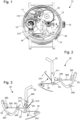
- the present invention relates to a watch 10 comprising a watch movement provided with a “stop seconds” function as shown schematically in the figure 1 .
- the watch 10 in a preferred application of the present invention, is a sympathetic watch intended to cooperate with a sympathetic clock.
- the horological movement according to the present invention comprises a wheel set for a time value display, such as a seconds wheel set, intended to carry a seconds display 11, such as a seconds hand.
- the watch movement further comprises an energy source, such as a barrel 12, connected to the seconds wheel to drive it in rotation, in a manner known to those skilled in the art, and a regulator 13 intended to regulate the movement of the seconds wheel, as seen on the figure 1 .
- an energy source such as a barrel 12
- a regulator 13 intended to regulate the movement of the seconds wheel, as seen on the figure 1 .
- the watch movement also includes a control mechanism 20, as illustrated in the figures 2 to 6 , adapted to occupy an active state in which it cooperates, on the one hand, with the regulator 13 to immobilize it, and on the other hand, with the mobile of the seconds to drive it in rotation in a predefined position.
- the control mechanism 20 is also suitable for occupying an inactive state in which it releases, on the one hand, the regulator 13 so that the latter is capable of regulating the movement of the seconds mobile, and on the other hand, the mobile seconds so as to authorize its movement.
- control mechanism 20 comprises two motion transmission modules each intended to be connected to its own control member, said transmission modules being both configured to drive the control mechanism 20 between its inactive state and its active state, upon request from the control device to which they are connected.
- control mechanism 20 comprises a stop lever 21 arranged in a rotatable manner and occupying an active position in which it bears against the regulator 13 when the control mechanism 20 is in the active state. More specifically, as shown by the figures 1 to 6 , the stop lever 21 comprises a support arm 210 intended to bear by its free end against a balance of the regulator 13, and a transmission arm 211 intended to receive forces causing the movement of the stop lever 21.
- the control mechanism 20 also comprises a hammer 22 arranged in a rotatable manner, and occupying an active position in which it rests against a heart cam 110 integral with the seconds wheel set when the control mechanism 20 is in the active state.
- control mechanism 20 comprises a transmission rocker 23 carrying a satellite rocker 261 configured so as to connect the transmission modules with the stop lever 21 and the hammer 22, and so as to occupy an active position when the mechanism of control 20 occupies the active state in which said rocker drives said stop lever 21 and said hammer 22 into their active position.
- the control members when one of the control members is activated, it causes the movement of the transmission module to which it is connected, and the driving of the stop lever 21 and of the hammer 22 via the rocker of the satellite rocker. 261.
- the satellite rocker 261 is fixed in a rotatable manner on the transmission rocker 23.
- the stop lever 21, the hammer 22 and the transmission rocker 23 are rotatable around the same axis of rotation. This characteristic advantageously makes it possible to simplify the control mechanism 20.
- the control mechanism 20 comprises a spring 24 making it possible to force the control mechanism 20 towards its active state. More specifically, the spring 24 is configured so as to urge the hammer 22 and the stop lever 21 towards their respective active position, the latter being arranged in abutment against a retaining element carried by the satellite rocker 261. In other words, the spring 24 applies a return force to the hammer 22 which transmits it to the stop lever 21 and to the transmission lever 23 via the retaining element.
- the hammer 22 is interposed between the stop lever 21 and the transmission rocker 23.
- first transmission module comprises a transmission lever 25 extending between two ends and being connected to one of the control members, called “first control member” at the level of a pivot 250 arranged between said ends. It should be noted that the characteristics of the first transmission module are identical in the two exemplary embodiments of the invention shown in the figures.
- the first control member is preferably formed by an actuator of the watch 10, such as a pusher 14, adapted to cooperate with an actuator of a sympathetic clock.
- actuators are not described in more detail in this text insofar as they do not constitute as such the object of the present invention.
- the transmission lever 25 is rotatable at one of its ends and comprises at its other end a protrusion 251 by which it cooperates with the transmission rocker 23 so as to drive it in rotation when it is urged by the first controller.
- the protrusion 251 can take the form of a tenon and rests, as shown in the figures, on one of the arms, called “first arm” 230, of the transmission rocker 23 so as to oppose the force exerted by the spring 24 tending to drive said stop lever 21 and said hammer 22 into their active position.
- the other transmission module is arranged opposite to the first transmission module relative to the transmission rocker 23, to the hammer 22 and to the stop lever 21.
- the transmission rocker 23, the hammer 22 and the stop lever 21 are interposed between the two transmission modules.
- the second transmission module comprises a link rocker 260 intended to be connected to one of the control elements, called the “second control element”.
- link rocker 260 and the satellite rocker 261 are connected to each other by a connecting rod 262, said connecting rod 262 making it possible to transmit to the satellite rocker 261 a movement of the connecting rocker 260 generated by the actuation of the second order.
- the second control member is preferably formed by a crown 15 of the watch 10, intended to be manipulated by the user of said watch 10.
- the crown 15 can be connected by a rod movable in translation to a pull tab, not shown in the figures.
- the pull tab is advantageously configured to transmit a rotational movement to the link rocker 260 following a translation of the crown 15.
- the pull tab can be connected to the link rocker 260 by a pivot.
- the satellite rocker 261 is arranged to cooperate with the hammer 22 and the stop lever 21 so that, when the second control member is urged to drive the control mechanism 20 in its inactive state, it opposes the force exerted by the spring 24 tending to drive said stop lever 21 and said hammer 22 into their inactive position, and this, without causing the rotation of the transmission rocker 23.
- the satellite rocker 261 is arranged to cooperate with the hammer 22 and the stop lever 21 so that, when the second control member is urged to drive the control mechanism 20 into its active state, it allows the release said stop lever 21 and said hammer 22 towards their active position under the effect of the force exerted by the spring 24, and this, without causing the rotation of the transmission rocker 23.
- the satellite rocker 261 is fixed in a rotatable manner, for example in the manner of a mobile satellite, on the transmission rocker 23, and more particularly on one of the arms of the latter called "second arm" 231.
- the two transmission modules are linked to the hammer 22 and to the stop lever 21 by the transmission rocker 23 and by the satellite rocker 261, for example in the manner of a differential gear train.
- the connecting rod 262 is hinged to a first wing 263 of the satellite rocker 261, said first wing 263 being opposed to a second wing 264 comprising the retaining element against which the hammer 22 and the stop lever 21 are arranged in support.
- the first control member is arranged so as to cause the pivoting of the transmission rocker 23, while the connecting rod 262 and the connecting rocker 260 are stationary, which constrains the rotation of the satellite rocker 261 relative to the end of the connecting rod 262 to which the first wing 263 is connected, and causes the hammer 22 and the stop lever 21 by the tenon 270.
- the actuation of the link rocker 260 by the second control member so as to drive the control mechanism 20 in the active state, releases the pivoting, relative to the transmission rocker 23 and in a first direction of rotation, of the satellite rocker 261 by means of the connecting rod 262, allowing to release the rotation of the hammer 22 and of the lever stop 21 under the effect of the force generated by the spring 24.
- the second control member is arranged so as to cause the pivoting of the link rocker 260, while the transmission lever 25 and the transmission rocker 23 are stationary, which constrains the rotation of the rocker satellite 261 with respect to the transmission rocker 23 and drives the hammer 22 and the stop lever 21 by the tenon 270.
- the retaining element is formed by a tenon 270 extending from a surface of the second wing 264 of the satellite rocker 261 and engaging in a cavity 271 that comprises the transmission arm 211 of the stop lever 21.
- the cavity 271 is oblong in shape so as to allow the sliding of the tenon 270 within said cavity 271.
- Such a translation is caused for example when the satellite rocker 261 is rotated relative to the transmission rocker 23, under the influence of the second control member.
- the cavity in other exemplary embodiments, can be made on the second wing 264 of the satellite rocker 261 and that the tenon 270 can extend from a surface of the transmission arm 211 of the stop lever 21.
- first and the second control member can be formed by any appropriate element, such as a bezel, a pusher, a lever, etc.
- the arrangement of the hammer 22 and of the stop lever 21 can be reversed in the sense that the stop lever 21 can be interposed between the hammer 22 and the transmission rocker 23, the tenon then being engaged in a cavity made in the hammer. 22 and the spring 24 pressing against the stop lever 21.
Landscapes
- Physics & Mathematics (AREA)
- General Physics & Mathematics (AREA)
- Measurement Of Unknown Time Intervals (AREA)
- Percussion Or Vibration Massage (AREA)
- Electric Clocks (AREA)
- Electromechanical Clocks (AREA)
Abstract
Description
- L'invention relève du domaine de l'horlogerie, et notamment des mouvements horlogers.
- Plus particulièrement, l'invention concerne un mouvement horloger comportant une fonction « stop seconde » actionnable à partir de deux organes de commande distincts.
- La fonction « stop seconde » est une complication horlogère bien connue et permet d'immobiliser l'afficheur des secondes afin de pouvoir mettre à l'heure une montre de façon plus précise.
- Cette fonction est mise en œuvre par l'immobilisation du régulateur de la montre par un mécanisme d'arrêt adapté, suite à la sollicitation par un utilisateur d'une couronne de la montre. Une fois la montre mise à l'heure, le régulateur est libéré, par une autre sollicitation de la couronne.
- Dans certains mouvements horlogers de l'état de la technique, la fonction « stop seconde » est associée à une mise à une position de référence de l'afficheur des secondes, la position de référence correspondant généralement à la position zéro, c'est-à-dire 12h00.
- L'association de ces fonctions permet de mettre à l'heure encore plus précisément la montre.
- Il existe toutefois un besoin, pour certaines applications, non couvert par les dispositifs de l'état de la technique, consistant à disposer d'une montre dont les fonctions stop seconde et de remise à zéro de l'afficheur des secondes puissent être mise en œuvre par des moyens distincts, et ce dans une conception la plus simple possible.
- L'invention résout les inconvénients précités.
- À cet effet, la présente invention concerne un mouvement horloger comprenant un mobile d'un afficheur d'une valeur temporelle, tel qu'un mobile des secondes, une source d'énergie reliée à ce mobile d'un afficheur pour l'entraîner en rotation, et un régulateur destiné à réguler le mouvement de ce mobile d'un afficheur, ledit mouvement horloger comprenant un mécanisme de contrôle adapté à occuper un état actif dans lequel il coopère avec le régulateur pour l'immobiliser, et un état inactif dans lequel il libère le régulateur de sorte que ce dernier soit apte à régulariser le mouvement du mobile d'un afficheur d'une valeur temporelle.
- Le mécanisme de contrôle comporte deux modules de transmission de mouvement chacun destiné à être relié à un organe de commande propre, chacun desdits modules étant configuré pour entraîner le mécanisme de contrôle entre son état inactif et son état actif sur sollicitation de l'organe de commande auquel il est relié.
- Dans des modes particuliers de réalisation, l'invention peut comporter en outre l'une ou plusieurs des caractéristiques suivantes, prises isolément ou selon toutes les combinaisons techniquement possibles.
- Dans des modes particuliers de réalisation, le mécanisme de contrôle est adapté à occuper un état actif dans lequel il coopère avec le mobile d'un afficheur d'une valeur temporelle pour l'entraîner en rotation dans une position prédéfinie, et un état inactif dans lequel il libère le mobile d'un afficheur d'une valeur temporelle de sorte à autoriser son déplacement.
- Dans des modes particuliers de réalisation, le mécanisme de contrôle comporte :
- un levier stop agencé mobile en rotation et occupant une position active dans laquelle il repose en appui contre le régulateur lorsque le mécanisme de contrôle occupe l'état actif ;
- une bascule de transmission portant une bascule satellite configurée de sorte à relier les modules de transmission avec le levier stop et à occuper une position active, lorsque le mécanisme de contrôle occupe l'état actif, dans laquelle ladite bascule satellite entraîne ledit levier stop dans sa position active.
- Dans des modes particuliers de réalisation, le mécanisme de contrôle comporte un marteau agencé mobile en rotation, la bascule satellite étant configurée de sorte à relier les modules de transmission et le marteau de sorte que ledit marteau occupe une position active dans laquelle il repose en appui contre une came cœur solidaire du mobile d'un afficheur d'une valeur temporelle lorsque la bascule satellite occupe la position active.
- Dans des modes particuliers de réalisation, le levier stop, le marteau et la bascule de transmission sont mobiles en rotation autour d'un même axe de rotation.
- Dans des modes particuliers de réalisation, le marteau et le levier stop sont sollicités vers leur position active respective par un ressort et agencés en butée contre un élément de retenu de la bascule satellite.
- Dans des modes particuliers de réalisation, l'un des modules de transmission, dit « premier module de transmission », comporte un levier de transmission s'étendant entre deux extrémités, ledit levier étant mobile en rotation au niveau d'une de ses extrémités et comprenant à l'autre extrémité une excroissance par laquelle il coopère avec la bascule de transmission de sorte à l'entraîner en rotation lorsqu'il est sollicité par l'un des organe de commande, dit « premier organe de commande », auquel il est relié.
- Dans des modes particuliers de réalisation, le levier de transmission est agencé en appui contre un bras de la bascule de transmission de sorte à s'opposer à l'effort exercé par le ressort tendant à entraîner ledit levier stop et ledit marteau dans leur position active.
- Dans des modes particuliers de réalisation, l'un des modules de transmission, dit « second module de transmission », comporte une bascule de liaison destinée à être reliée à l'un des organes de commande, dit « second organe de commande », la bascule de liaison et la bascule satellite étant reliées l'une à l'autre par une bielle, de sorte que la sollicitation du second organe de commande provoque la rotation de la bascule satellite.
- Dans des modes particuliers de réalisation, la bielle est fixée sur une première aile de la bascule satellite, ladite première aile étant opposée à une seconde aile comprenant l'élément de retenu contre lequel le marteau et le levier stop sont agencés en appui.
- Dans des modes particuliers de réalisation, le levier stop et le marteau sont agencés en appui contre un tenon s'étendant depuis une surface de la seconde aile de la bascule satellite, ledit tenon étant agencé de sorte à constituer l'élément de retenu.
- Dans des modes particuliers de réalisation, le tenon est engagé dans une cavité que comporte le levier stop, le ressort étant agencé en appui seulement contre le marteau.
- Selon un autre objet, la présente invention concerne une montre comprenant un mouvement horloger tel que décrit précédemment, et dans laquelle les organes de commande sont constitués par une couronne et par un poussoir.
- Dans des modes particuliers de réalisation de l'invention, le poussoir est adapté à coopérer avec un actionneur d'une pendule sympathique, de sorte à agir sur le module de transmission avec lequel il est relié sur sollicitation dudit actionneur.
- D'autres caractéristiques et avantages de l'invention apparaîtront à la lecture de la description détaillée suivante donnée à titre d'exemple nullement limitatif, en référence aux dessins annexés dans lesquels :
- la
figure 1 représente schématiquement une vue de face d'une montre comprenant un mouvement horloger selon un exemple de réalisation de la présente l'invention ; - la
figure 2 représente une vue de face d'un mécanisme de contrôle du mouvement horloger de lafigure 1 ; - la
figure 3 représente une vue de derrière du mécanisme de contrôle du mouvement horloger de lafigure 2 ; - la
figure 4 représente une vue de face du mécanisme de contrôle du mouvement horloger selon un autre exemple de réalisation de la présente invention ; - la
figure 5 représente une vue de derrière du mécanisme de contrôle du mouvement horloger de lafigure 4 ; - la
figure 6 représente une vue en perspective d'un détail du mécanisme de contrôle du mouvement horloger illustré sur lesfigures 4 et 5 . - La présente invention concerne une montre 10 comprenant un mouvement horloger doté d'une fonction « stop seconde » tel que schématiquement représenté sur la
figure 1 . Il y a lieu de noter que la montre 10, dans une application préférée de la présente invention, est une montre sympathique destinée à coopérer avec une pendule sympathique. - Le mouvement horloger selon la présente invention comprend un mobile d'un afficheur d'une valeur temporelle, tel qu'un mobile des secondes, destiné à porter un afficheur des secondes 11, tel qu'une aiguille des secondes.
- Le mouvement horloger comprend, en outre, une source d'énergie, tel qu'un barillet 12, reliée au mobile des secondes pour l'entraîner en rotation, de façon connue par l'homme du métier, et un régulateur 13 destiné à réguler le mouvement du mobile des secondes, comme visible sur la
figure 1 . - Le mouvement horloger comprend également un mécanisme de contrôle 20, tel qu'illustré sur les
figures 2 à 6 , adapté à occuper un état actif dans lequel il coopère, d'une part, avec le régulateur 13 pour l'immobiliser, et d'autre part, avec le mobile des secondes pour l'entraîner en rotation dans une position prédéfinie. Le mécanisme de contrôle 20 est par ailleurs adapté à occuper un état inactif dans lequel il libère, d'une part, le régulateur 13 de sorte que ce dernier soit apte à régulariser le mouvement du mobile des secondes, et d'autre part, le mobile des secondes de sorte à autoriser son déplacement. - Avantageusement, le mécanisme de contrôle 20 comporte deux modules de transmission de mouvement chacun destiné à être relié à un organe de commande propre, lesdits modules de transmission étant l'un et l'autre configurés pour entraîner le mécanisme de contrôle 20 entre son état inactif et son état actif, sur sollicitation de l'organe de commande auquel ils sont reliés.
- Plus particulièrement, le mécanisme de contrôle 20 comporte un levier stop 21 agencé de façon mobile en rotation et occupant une position active dans laquelle il repose en appui contre le régulateur 13 lorsque le mécanisme de contrôle 20 occupe l'état actif. Plus précisément, comme le montrent les
figures 1 à 6 , le levier stop 21 comprend un bras d'appui 210 destiné à reposer en appui par son extrémité libre contre un balancier du régulateur 13, et un bras de transmission 211 destiné à recevoir des efforts entraînant le déplacement du levier stop 21. - Le mécanisme de contrôle 20 comporte également un marteau 22 agencé de manière mobile en rotation, et occupant une position active dans laquelle il repose en appui contre une came cœur 110 solidaire du mobile des secondes lorsque le mécanisme de contrôle 20 occupe l'état actif.
- Par ailleurs, le mécanisme de contrôle 20 comprend une bascule de transmission 23 portant une bascule satellite 261 configurée de sorte à relier les modules de transmission avec le levier stop 21 et le marteau 22, et de sorte à occuper une position active lorsque le mécanisme de contrôle 20 occupe l'état actif dans laquelle ladite bascule entraîne ledit levier stop 21 et ledit marteau 22 dans leur position active. Autrement dit, lorsque l'un des organes de commande est sollicité, il entraîne le déplacement du module de transmission auquel il est relié, et l'entraînement du levier stop 21 et du marteau 22 par l'intermédiaire de la bascule de la bascule satellite 261.
- La bascule satellite 261 est fixée de manière mobile en rotation sur la bascule de transmission 23.
- Préférentiellement, tel que représenté sur les
figures 1 à 6 , le levier stop 21, le marteau 22 et la bascule de transmission 23 sont mobiles en rotation autour d'un même axe de rotation. Cette caractéristique permet avantageusement de simplifier le mécanisme de contrôle 20. - Le mécanisme de contrôle 20 comprend un ressort 24 permettant de contraindre le mécanisme de contrôle 20 vers son état actif. Plus précisément, le ressort 24 est configuré de sorte à solliciter le marteau 22 et le levier stop 21 vers leur position active respective, ces derniers étant agencés en butée contre un élément de retenu porté par la bascule satellite 261. Autrement dit, le ressort 24 applique un effort de rappel sur le marteau 22 qui le transmet au levier stop 21 et à la bascule de transmission 23 par le biais de l'élément de retenu.
- Par ailleurs, dans ces exemples de réalisation de l'invention, le marteau 22 est interposé entre le levier stop 21 et la bascule de transmission 23.
- L'un des modules de transmission, dit « premier module de transmission », comporte un levier de transmission 25 s'étendant entre deux extrémités et étant relié à l'un des organes de commande, dit « premier organe de commande » au niveau d'un pivot 250 agencé entre lesdites extrémités. Il y a lieu de noter que les caractéristiques du premier module de transmission sont identiques dans les deux exemples de réalisation de l'invention représentés sur les figures.
- Le premier organe de commande est préférentiellement formé par un actionneur de la montre 10, tel qu'un poussoir 14, adapté à coopérer avec un actionneur d'une pendule sympathique. Ces actionneurs ne sont pas décrits plus en détail dans le présent texte dans la mesure où ils ne constituent pas en tant que tels l'objet de la présente invention.
- Le levier de transmission 25 est mobile en rotation au niveau d'une de ses extrémités et comprend à son autre extrémité une excroissance 251 par laquelle il coopère avec la bascule de transmission 23 de sorte à l'entraîner en rotation lorsqu'il est sollicité par le premier organe de commande. L'excroissance 251 peut prendre la forme d'un tenon et prend appui, comme l'illustrent les figures, sur l'un des bras, dit « premier bras » 230, de la bascule de transmission 23 de sorte à s'opposer à l'effort exercé par le ressort 24 tendant à entraîner ledit levier stop 21 et ledit marteau 22 dans leur position active.
- Dans les exemples de réalisation de l'invention représentés sur les figures, l'autre module de transmission, dit « second module de transmission », est agencé de façon opposé au premier module de transmission relativement à la bascule de transmission 23, au marteau 22 et au levier stop 21. Autrement dit, la bascule de transmission 23, le marteau 22 et le levier stop 21 sont interposés entre les deux modules de transmission.
- Comme représenté sur les
figures 3 et5 , le second module de transmission comporte une bascule de liaison 260 destinée à être reliée à l'un des organes de commande, dit « second organe de commande ». La bascule de liaison 260 et la bascule satellite 261 sont reliées l'une à l'autre par une bielle 262, ladite bielle 262 permettant de transmettre à la bascule satellite 261 un mouvement de la bascule de liaison 260 généré par la sollicitation du second organe de commande. - Le second organe de commande est préférentiellement formé par une couronne 15 de la montre 10, destinée à être manipulée par l'utilisateur de ladite montre 10. De façon connue en soi, la couronne 15 peut être reliée par une tige mobile en translation à une tirette, non représentées sur les figures. La tirette est avantageusement configurée pour transmettre un mouvement de rotation à la bascule de liaison 260 suite à une translation de la couronne 15. Par exemple la tirette peut être reliée à la bascule de liaison 260 par un pivot.
- La bascule satellite 261 est agencée pour coopérer avec le marteau 22 et le levier stop 21 de sorte que, lorsque le second organe de commande est sollicité pour entraîner le mécanisme de contrôle 20 dans son état inactif, elle s'oppose à l'effort exercé par le ressort 24 tendant à entraîner ledit levier stop 21 et ledit marteau 22 dans leur position inactive, et ce, sans provoquer la rotation de la bascule de transmission 23.
- A l'inverse, la bascule satellite 261 est agencée pour coopérer avec le marteau 22 et le levier stop 21 de sorte que, lorsque le second organe de commande est sollicité pour entraîner le mécanisme de contrôle 20 dans son état actif, elle permette la libération dudit levier stop 21 et dudit marteau 22 vers leur position active sous l'effet de l'effort exercé par le ressort 24, et ce, sans provoquer la rotation de la bascule de transmission 23.
- Plus précisément, dans les exemples de réalisation représentés sur les
figures 2 à 6 , la bascule satellite 261 est fixée de manière mobile en rotation, par exemple à la manière d'un mobile satellite, sur la bascule de transmission 23, et plus particulièrement sur un des bras de cette dernière dit « second bras » 231. - En résumé, les deux modules de transmission sont liés au marteau 22 et au levier stop 21 par la bascule de transmission 23 et par la bascule satellite 261, par exemple à la manière d'un rouage différentiel.
- Avantageusement, comme l'illustrent les
figures 3 et5 , la bielle 262 est articulée à une première aile 263 de la bascule satellite 261, ladite première aile 263 étant opposée à une seconde aile 264 comprenant l'élément de retenu contre lequel le marteau 22 et le levier stop 21 sont agencés en appui. - On comprend ici que la sollicitation du levier de transmission 25 par le premier organe de commande, de sorte à libérer le mécanisme de contrôle 20 dans vers son état actif, libère ledit levier pour un déplacement angulaire dans un premier sens de rotation permettant la rotation de la bascule de transmission 23 sous l'effet de l'effort généré par le ressort 24, ledit effort étant transmis à ladite bascule de transmission 23 par l'appui du marteau 22 sur la seconde aile 264 de la bascule satellite 261.
- En d'autres termes, le premier organe de commande est agencé de sorte à provoquer le pivotement de la bascule de transmission 23, alors que la bielle 262 et la bascule de liaison 260 sont immobiles, ce qui contraint la rotation de la bascule satellite 261 par rapport à l'extrémité de la bielle 262 à laquelle la première aile 263 est reliée, et entraine le marteau 22 et le levier stop 21 par le tenon 270.
- A l'inverse, la sollicitation du levier de transmission 25 par le premier organe de commande, de sorte à entraîner le mécanisme de contrôle 20 dans l'état inactif, contraint ledit levier à un déplacement angulaire dans un second sens de rotation ayant pour effet d'entraîner la rotation de la bascule de transmission 23 à l'encontre de l'effort généré par le ressort 24, ledit effort étant transmis à ladite bascule de transmission 23 par l'appui du marteau 22 sur la seconde aile 264 de la bascule satellite 261.
- Par ailleurs, la sollicitation de la bascule de liaison 260 par le second organe de commande, de sorte à entraîner le mécanisme de contrôle 20 dans l'état actif, libère le pivotement, par rapport à la bascule de transmission 23 et dans un premier sens de rotation, de la bascule satellite 261 par le biais de la bielle 262, permettant libérer la rotation du marteau 22 et du levier stop 21 sous l'effet de l'effort généré par le ressort 24.
- En d'autres termes, le second organe de commande est agencé de sorte à provoquer le pivotement de la bascule de liaison 260, alors que le levier de transmission 25 et la bascule de transmission 23 sont immobiles, ce qui contraint la rotation de la bascule satellite 261 par rapport à la bascule de transmission 23 et entraine le marteau 22 et le levier stop 21 par le tenon 270.
- A l'inverse, la sollicitation de la bascule de liaison 260 par le second organe de commande, de sorte à entraîner le mécanisme de contrôle 20 dans l'état inactif, contraint le pivotement, par rapport à la bascule de transmission 23 et dans un second sens de rotation, de la bascule satellite 261 par le biais de la bielle 262, permettant d'entraîner la rotation du marteau 22 et du levier stop 21 à l'encontre de l'effort généré par le ressort 24.
- En particulier, dans l'exemple de réalisation représenté sur les
figures 4 à 6 , l'élément de retenu est formé par un tenon 270 s'étendant depuis une surface de la seconde aile 264 de la bascule satellite 261 et s'engageant dans une cavité 271 que comporte le bras de transmission 211 du levier stop 21. - Plus précisément, comme le montre en détail la
figure 6 , dans cet exemple de réalisation, la cavité 271 est de forme oblongue de sorte à autoriser le coulissement du tenon 270 au sein de ladite cavité 271. Une telle translation est occasionnée par exemple lorsque la bascule satellite 261 est entraînée en rotation par rapport à la bascule de transmission 23, sous la sollicitation du second organe de commande. - Il y a lieu de noter que la cavité, dans d'autres exemples de réalisation, peut être réalisée sur seconde aile 264 de la bascule satellite 261 et que le tenon 270 peut s'étendre depuis une surface du bras de transmission 211 du levier stop 21.
- De manière plus générale, il est à noter que les exemples de réalisation considérés ci-dessus ont été décrits à titre d'exemples non limitatifs, et que d'autres variantes sont par conséquent envisageables.
- Notamment, le premier et le second organe de commande peuvent être formés par tout élément approprié, tel qu'une lunette, un poussoir, un levier, etc.
- Par ailleurs, la disposition du marteau 22 et du levier stop 21 peut être inversée dans le sens où le levier stop 21 peut être interposé entre le marteau 22 et la bascule de transmission 23, le tenon étant lors engagé dans une cavité réalisée dans le marteau 22 et le ressort 24 prenant appuis contre le levier stop 21.
Claims (14)
- Mouvement horloger comprenant un mobile d'un afficheur d'une valeur temporelle (11), une source d'énergie reliée à ce mobile d'un afficheur pour l'entraîner en rotation, et un régulateur (13) destiné à réguler le mouvement de ce mobile d'un afficheur, ledit mouvement horloger comprenant un mécanisme de contrôle (20) adapté à occuper un état actif dans lequel il coopère avec le régulateur (13) pour l'immobiliser, et un état inactif dans lequel il libère le régulateur (13) de sorte que ce dernier soit apte à régulariser le mouvement du mobile d'un afficheur d'une valeur temporelle (11), le mouvement horloger étant caractérisé en ce que le mécanisme de contrôle (20) comporte deux modules de transmission de mouvement chacun destiné à être relié à un organe de commande propre, chacun desdits modules étant configuré pour entraîner le mécanisme de contrôle (20) entre son état inactif et son état actif sur sollicitation de l'organe de commande auquel il est relié.
- Mouvement horloger selon la revendication 1, dans laquelle le mécanisme de contrôle (20) est adapté à occuper un état actif dans lequel il coopère avec le mobile d'un afficheur d'une valeur temporelle (11) pour l'entraîner en rotation dans une position prédéfinie, et un état inactif dans lequel il libère ledit mobile de sorte à autoriser son déplacement.
- Mouvement horloger selon la revendication 1 ou 2, dans lequel le mécanisme de contrôle (20) comporte :- un levier stop (21) agencé mobile en rotation et occupant une position active dans laquelle il repose en appui contre le régulateur (13) lorsque le mécanisme de contrôle (20) occupe l'état actif ;- une bascule de transmission (23) portant une bascule satellite (261) configurée de sorte à relier les modules de transmission avec le levier stop (21) et à occuper une position active, lorsque le mécanisme de contrôle (20) occupe l'état actif, dans laquelle ladite bascule satellite (261) entraîne ledit levier stop (21) dans sa position active.
- Mouvement horloger selon les revendications 2 et 3, dans lequel le mécanisme de contrôle (20) comporte un marteau (22) agencé mobile en rotation, la bascule satellite (261) étant configurée de sorte à relier les modules de transmission et le marteau (22) de sorte que ledit marteau (22) occupe une position active dans laquelle il repose en appui contre une came cœur (110) solidaire du mobile d'un afficheur d'une valeur temporelle (11) lorsque la bascule satellite (261) occupe la position active.
- Mouvement horloger selon les revendications 3 et 4, dans lequel. le levier stop (21), le marteau (22) et la bascule de transmission (23) sont mobiles en rotation autour d'un même axe de rotation.
- Mouvement horloger selon les revendications 3 et 4, dans lequel le marteau (22) et le levier stop (21) sont sollicités vers leur position active respective par un ressort (24) et agencés en butée contre un élément de retenu de la bascule satellite (261).
- Mouvement horloger selon l'une des revendications 3 à 6, dans lequel l'un des modules de transmission, dit « premier module de transmission », comporte un levier de transmission (25) s'étendant entre deux extrémités, ledit levier étant mobile en rotation au niveau d'une de ses extrémités et comprenant à l'autre extrémité une excroissance (251) par laquelle il coopère avec la bascule de transmission (23) de sorte à l'entraîner en rotation lorsqu'il est sollicité par l'un des organe de commande, dit « premier organe de commande », auquel il est relié.
- Mouvement horloger selon les revendications 6 et 7, dans lequel le levier de transmission (25) est agencé en appui contre un bras (230) de la bascule de transmission (23) de sorte à s'opposer à l'effort exercé par le ressort (24) tendant à entraîner ledit levier stop (21) et ledit marteau (22) dans leur position active.
- Mouvement horloger selon l'une des revendications 3 à 8, dans lequel l'un des modules de transmission, dit « second module de transmission », comporte une bascule de liaison (260) destinée à être reliée à l'un des organes de commande, dit « second organe de commande », la bascule de liaison (260) et la bascule satellite (261) étant reliées l'une à l'autre par une bielle (262), de sorte que la sollicitation du second organe de commande provoque la rotation de la bascule satellite (261).
- Mouvement horloger selon les revendications 6 et 9, dans lequel la bielle (262) est fixée sur une première aile (263) de la bascule satellite (261), ladite première aile (263) étant opposée à une seconde aile (264) comprenant l'élément de retenu contre lequel le marteau (22) et le levier stop (21) sont agencés en appui.
- Mouvement horloger selon la revendication 10, dans lequel le levier stop (21) et le marteau (22) sont agencés en appui contre un tenon (270) s'étendant depuis une surface de la seconde aile (264) de la bascule satellite (261), ledit tenon (270) étant agencé de sorte à constituer l'élément de retenu.
- Mouvement horloger selon la revendication 11, dans lequel le tenon (270) est engagé dans une cavité (271) que comporte le levier stop (21), le ressort (24) étant agencé en appui seulement contre le marteau (22).
- Montre (10) comprenant un mouvement horloger selon l'une des revendications 1 à 12, caractérisée en ce que les organes de commande sont constitués par une couronne (15) et par un poussoir (14).
- Montre (10) selon la revendication 13, dans laquelle le poussoir (14) est adapté à coopérer avec un actionneur d'une pendule sympathique, de sorte à agir sur le module de transmission avec lequel il est relié, sur sollicitation dudit actionneur.
Priority Applications (4)
| Application Number | Priority Date | Filing Date | Title |
|---|---|---|---|
| EP21217365.2A EP4202570B1 (fr) | 2021-12-23 | 2021-12-23 | Mouvement horloger comprenant une fonction « stop seconde » actionnable à partir de deux organes de commande distincts |
| JP2022162144A JP7454026B2 (ja) | 2021-12-23 | 2022-10-07 | 2つの別個の作動部材により作動可能な「ストップセコンド」機能を備える時計ムーブメント |
| US17/965,287 US12339624B2 (en) | 2021-12-23 | 2022-10-13 | Horological movement comprising a stop-seconds function that can be operated from two separate actuating members |
| CN202211663389.9A CN116339106A (zh) | 2021-12-23 | 2022-12-23 | 包括可由两个分开的致动构件操作的“停秒”功能的钟表机芯 |
Applications Claiming Priority (1)
| Application Number | Priority Date | Filing Date | Title |
|---|---|---|---|
| EP21217365.2A EP4202570B1 (fr) | 2021-12-23 | 2021-12-23 | Mouvement horloger comprenant une fonction « stop seconde » actionnable à partir de deux organes de commande distincts |
Publications (2)
| Publication Number | Publication Date |
|---|---|
| EP4202570A1 true EP4202570A1 (fr) | 2023-06-28 |
| EP4202570B1 EP4202570B1 (fr) | 2024-07-03 |
Family
ID=79024574
Family Applications (1)
| Application Number | Title | Priority Date | Filing Date |
|---|---|---|---|
| EP21217365.2A Active EP4202570B1 (fr) | 2021-12-23 | 2021-12-23 | Mouvement horloger comprenant une fonction « stop seconde » actionnable à partir de deux organes de commande distincts |
Country Status (4)
| Country | Link |
|---|---|
| US (1) | US12339624B2 (fr) |
| EP (1) | EP4202570B1 (fr) |
| JP (1) | JP7454026B2 (fr) |
| CN (1) | CN116339106A (fr) |
Citations (2)
| Publication number | Priority date | Publication date | Assignee | Title |
|---|---|---|---|---|
| CH698878B1 (fr) * | 2006-03-28 | 2009-11-30 | Chopard Manufacture Sa | Remise à zéro de l'aiguille des secondes dans une pièce d'horlogerie. |
| EP3407142B1 (fr) * | 2017-05-22 | 2020-01-29 | Officine Panerai AG | Mouvement horloger à fonction "stop second" |
Family Cites Families (8)
| Publication number | Priority date | Publication date | Assignee | Title |
|---|---|---|---|---|
| ATE316663T1 (de) * | 2002-10-07 | 2006-02-15 | Vaucher Mft Fleurier Sa | Chronographenuhrwerk |
| ATE457480T1 (de) * | 2002-10-07 | 2010-02-15 | Vaucher Mft Fleurier Sa | Chronographuhr |
| EP2453322B1 (fr) * | 2010-11-16 | 2013-07-17 | Omega SA | Correcteur rapide d'indicateur d'une grandeur temporelle pour pièce d'horlogerie |
| EP2701015B1 (fr) * | 2012-08-21 | 2018-11-14 | Blancpain SA. | Dispositif de correction de fonctions affichées par une pièce d'horlogerie |
| US8923096B1 (en) * | 2013-10-17 | 2014-12-30 | Timex Group Usa, Inc. | Method of displaying elapsed time on a wristworn device and wristworn device displaying same |
| JP6485779B2 (ja) * | 2014-02-19 | 2019-03-20 | ショパール テクノロジーズ エスエー | 計時器用の時打ち機構 |
| JP6121023B2 (ja) * | 2016-04-22 | 2017-04-26 | シチズン時計株式会社 | 多機能時計用ムーブメントおよび多機能時計 |
| CH714362A2 (fr) * | 2017-11-23 | 2019-05-31 | Blancpain Sa | Montre avec mécanisme de sonnerie à régulateur et sécurité de mise à l'heure. |
-
2021
- 2021-12-23 EP EP21217365.2A patent/EP4202570B1/fr active Active
-
2022
- 2022-10-07 JP JP2022162144A patent/JP7454026B2/ja active Active
- 2022-10-13 US US17/965,287 patent/US12339624B2/en active Active
- 2022-12-23 CN CN202211663389.9A patent/CN116339106A/zh active Pending
Patent Citations (2)
| Publication number | Priority date | Publication date | Assignee | Title |
|---|---|---|---|---|
| CH698878B1 (fr) * | 2006-03-28 | 2009-11-30 | Chopard Manufacture Sa | Remise à zéro de l'aiguille des secondes dans une pièce d'horlogerie. |
| EP3407142B1 (fr) * | 2017-05-22 | 2020-01-29 | Officine Panerai AG | Mouvement horloger à fonction "stop second" |
Also Published As
| Publication number | Publication date |
|---|---|
| US20230205138A1 (en) | 2023-06-29 |
| US12339624B2 (en) | 2025-06-24 |
| CN116339106A (zh) | 2023-06-27 |
| JP7454026B2 (ja) | 2024-03-21 |
| EP4202570B1 (fr) | 2024-07-03 |
| JP2023094530A (ja) | 2023-07-05 |
Similar Documents
| Publication | Publication Date | Title |
|---|---|---|
| EP2073078B1 (fr) | Marteau bistable pour mécanisme de chronographe | |
| EP2945024B1 (fr) | Bascule d'horlogerie | |
| EP3483663B1 (fr) | Dispositif d'entraînement pour système de calendrier horloger | |
| EP2010971A2 (fr) | Mouvement pour piece d'horlogerie a affichage retrograde | |
| EP2269119B1 (fr) | Dispositif antichoc pour un organe de commande d'une pièce d'horlogerie | |
| EP2541346A2 (fr) | Dispositif de remise dans une position prédéterminée d'un organe indicateur d'une grandeur liée au temps | |
| EP2073079A2 (fr) | Mécanisme de chronographe, mouvement horloger et pièce d'horlogerie comprenant un tel mécanisme | |
| EP3144743A1 (fr) | Mouvement horloger comprenant un mécanisme de correction de la date | |
| EP4202570B1 (fr) | Mouvement horloger comprenant une fonction « stop seconde » actionnable à partir de deux organes de commande distincts | |
| CH719312A2 (fr) | Mouvement horloger comprenant une fonction „stop seconde“ actionnable à partir de deux organes de commande distincts. | |
| CH718458A9 (fr) | Mécanisme d'actionnement pour mouvement horloger, en particulier mécanisme de chronographe comportant un tel mécanisme d'actionnement. | |
| CH716422B1 (fr) | Ensemble limiteur d'horlogerie pour une montre comportant au moins un tourbillon ou un carrousel. | |
| EP2639656A1 (fr) | Dispositif de commande pour montre de plongée | |
| EP2244138B1 (fr) | Dispositif de remontage d'une montre automatique comportant un système de débrayage | |
| EP3770694A1 (fr) | Stop-cage d'horlogerie comportant deux elements elastiques d'arret | |
| CH706108B1 (fr) | Dispositif stop-secondes simplifié pour mouvement horloger. | |
| EP3407142A1 (fr) | Mouvement horloger a fonction "stop second" | |
| EP4414792A1 (fr) | Mécanisme de correction d'au moins un premier et un deuxième dispositif indicateur d'une pièce d'horlogerie | |
| EP1960848B1 (fr) | Marteau pour piece d'horlogerie | |
| EP4254075B1 (fr) | Dispositif de commande déporté d'un mouvement horloger d'une montre et montre comprenant ledit dispositif de commande | |
| EP1890202A1 (fr) | Dispositif de commande pour pièce d'horlogerie | |
| CH702733B1 (fr) | Dispositif indicateur de réserve de marche intégré dans la masse oscillante d'un mouvement à remontage automatique. | |
| EP1791041A1 (fr) | Mouvement d'horlogerie | |
| CH722011A2 (fr) | Mécanisme de liaison cinématique pour mouvement horloger | |
| CH719563A2 (fr) | Dispositif de commande déporté d'un mouvement horloger d'une montre et montre comprenant ledit dispositif de commande. |
Legal Events
| Date | Code | Title | Description |
|---|---|---|---|
| PUAI | Public reference made under article 153(3) epc to a published international application that has entered the european phase |
Free format text: ORIGINAL CODE: 0009012 |
|
| STAA | Information on the status of an ep patent application or granted ep patent |
Free format text: STATUS: THE APPLICATION HAS BEEN PUBLISHED |
|
| AK | Designated contracting states |
Kind code of ref document: A1 Designated state(s): AL AT BE BG CH CY CZ DE DK EE ES FI FR GB GR HR HU IE IS IT LI LT LU LV MC MK MT NL NO PL PT RO RS SE SI SK SM TR |
|
| P01 | Opt-out of the competence of the unified patent court (upc) registered |
Effective date: 20231109 |
|
| STAA | Information on the status of an ep patent application or granted ep patent |
Free format text: STATUS: REQUEST FOR EXAMINATION WAS MADE |
|
| GRAP | Despatch of communication of intention to grant a patent |
Free format text: ORIGINAL CODE: EPIDOSNIGR1 |
|
| STAA | Information on the status of an ep patent application or granted ep patent |
Free format text: STATUS: GRANT OF PATENT IS INTENDED |
|
| 17P | Request for examination filed |
Effective date: 20240102 |
|
| RBV | Designated contracting states (corrected) |
Designated state(s): AL AT BE BG CH CY CZ DE DK EE ES FI FR GB GR HR HU IE IS IT LI LT LU LV MC MK MT NL NO PL PT RO RS SE SI SK SM TR |
|
| RIC1 | Information provided on ipc code assigned before grant |
Ipc: G04D 7/00 20060101ALN20240112BHEP Ipc: G04B 3/00 20060101ALN20240112BHEP Ipc: G04B 27/04 20060101AFI20240112BHEP |
|
| INTG | Intention to grant announced |
Effective date: 20240202 |
|
| RIC1 | Information provided on ipc code assigned before grant |
Ipc: G04D 7/00 20060101ALN20240122BHEP Ipc: G04B 3/00 20060101ALN20240122BHEP Ipc: G04B 27/04 20060101AFI20240122BHEP |
|
| GRAS | Grant fee paid |
Free format text: ORIGINAL CODE: EPIDOSNIGR3 |
|
| GRAA | (expected) grant |
Free format text: ORIGINAL CODE: 0009210 |
|
| STAA | Information on the status of an ep patent application or granted ep patent |
Free format text: STATUS: THE PATENT HAS BEEN GRANTED |
|
| AK | Designated contracting states |
Kind code of ref document: B1 Designated state(s): AL AT BE BG CH CY CZ DE DK EE ES FI FR GB GR HR HU IE IS IT LI LT LU LV MC MK MT NL NO PL PT RO RS SE SI SK SM TR |
|
| REG | Reference to a national code |
Ref country code: CH Ref legal event code: EP |
|
| REG | Reference to a national code |
Ref country code: DE Ref legal event code: R096 Ref document number: 602021015118 Country of ref document: DE |
|
| REG | Reference to a national code |
Ref country code: LT Ref legal event code: MG9D |
|
| REG | Reference to a national code |
Ref country code: NL Ref legal event code: MP Effective date: 20240703 |
|
| PG25 | Lapsed in a contracting state [announced via postgrant information from national office to epo] |
Ref country code: PT Free format text: LAPSE BECAUSE OF FAILURE TO SUBMIT A TRANSLATION OF THE DESCRIPTION OR TO PAY THE FEE WITHIN THE PRESCRIBED TIME-LIMIT Effective date: 20241104 |
|
| REG | Reference to a national code |
Ref country code: AT Ref legal event code: MK05 Ref document number: 1700457 Country of ref document: AT Kind code of ref document: T Effective date: 20240703 |
|
| PG25 | Lapsed in a contracting state [announced via postgrant information from national office to epo] |
Ref country code: NL Free format text: LAPSE BECAUSE OF FAILURE TO SUBMIT A TRANSLATION OF THE DESCRIPTION OR TO PAY THE FEE WITHIN THE PRESCRIBED TIME-LIMIT Effective date: 20240703 |
|
| PG25 | Lapsed in a contracting state [announced via postgrant information from national office to epo] |
Ref country code: PT Free format text: LAPSE BECAUSE OF FAILURE TO SUBMIT A TRANSLATION OF THE DESCRIPTION OR TO PAY THE FEE WITHIN THE PRESCRIBED TIME-LIMIT Effective date: 20241104 Ref country code: NL Free format text: LAPSE BECAUSE OF FAILURE TO SUBMIT A TRANSLATION OF THE DESCRIPTION OR TO PAY THE FEE WITHIN THE PRESCRIBED TIME-LIMIT Effective date: 20240703 |
|
| PG25 | Lapsed in a contracting state [announced via postgrant information from national office to epo] |
Ref country code: NO Free format text: LAPSE BECAUSE OF FAILURE TO SUBMIT A TRANSLATION OF THE DESCRIPTION OR TO PAY THE FEE WITHIN THE PRESCRIBED TIME-LIMIT Effective date: 20241003 |
|
| PG25 | Lapsed in a contracting state [announced via postgrant information from national office to epo] |
Ref country code: GR Free format text: LAPSE BECAUSE OF FAILURE TO SUBMIT A TRANSLATION OF THE DESCRIPTION OR TO PAY THE FEE WITHIN THE PRESCRIBED TIME-LIMIT Effective date: 20241004 Ref country code: FI Free format text: LAPSE BECAUSE OF FAILURE TO SUBMIT A TRANSLATION OF THE DESCRIPTION OR TO PAY THE FEE WITHIN THE PRESCRIBED TIME-LIMIT Effective date: 20240703 Ref country code: PL Free format text: LAPSE BECAUSE OF FAILURE TO SUBMIT A TRANSLATION OF THE DESCRIPTION OR TO PAY THE FEE WITHIN THE PRESCRIBED TIME-LIMIT Effective date: 20240703 |
|
| PG25 | Lapsed in a contracting state [announced via postgrant information from national office to epo] |
Ref country code: BG Free format text: LAPSE BECAUSE OF FAILURE TO SUBMIT A TRANSLATION OF THE DESCRIPTION OR TO PAY THE FEE WITHIN THE PRESCRIBED TIME-LIMIT Effective date: 20240703 |
|
| PG25 | Lapsed in a contracting state [announced via postgrant information from national office to epo] |
Ref country code: LV Free format text: LAPSE BECAUSE OF FAILURE TO SUBMIT A TRANSLATION OF THE DESCRIPTION OR TO PAY THE FEE WITHIN THE PRESCRIBED TIME-LIMIT Effective date: 20240703 |
|
| PG25 | Lapsed in a contracting state [announced via postgrant information from national office to epo] |
Ref country code: IS Free format text: LAPSE BECAUSE OF FAILURE TO SUBMIT A TRANSLATION OF THE DESCRIPTION OR TO PAY THE FEE WITHIN THE PRESCRIBED TIME-LIMIT Effective date: 20241103 Ref country code: AT Free format text: LAPSE BECAUSE OF FAILURE TO SUBMIT A TRANSLATION OF THE DESCRIPTION OR TO PAY THE FEE WITHIN THE PRESCRIBED TIME-LIMIT Effective date: 20240703 |
|
| PG25 | Lapsed in a contracting state [announced via postgrant information from national office to epo] |
Ref country code: HR Free format text: LAPSE BECAUSE OF FAILURE TO SUBMIT A TRANSLATION OF THE DESCRIPTION OR TO PAY THE FEE WITHIN THE PRESCRIBED TIME-LIMIT Effective date: 20240703 Ref country code: CZ Free format text: LAPSE BECAUSE OF FAILURE TO SUBMIT A TRANSLATION OF THE DESCRIPTION OR TO PAY THE FEE WITHIN THE PRESCRIBED TIME-LIMIT Effective date: 20240703 |
|
| PG25 | Lapsed in a contracting state [announced via postgrant information from national office to epo] |
Ref country code: RS Free format text: LAPSE BECAUSE OF FAILURE TO SUBMIT A TRANSLATION OF THE DESCRIPTION OR TO PAY THE FEE WITHIN THE PRESCRIBED TIME-LIMIT Effective date: 20241003 Ref country code: ES Free format text: LAPSE BECAUSE OF FAILURE TO SUBMIT A TRANSLATION OF THE DESCRIPTION OR TO PAY THE FEE WITHIN THE PRESCRIBED TIME-LIMIT Effective date: 20240703 |
|
| PG25 | Lapsed in a contracting state [announced via postgrant information from national office to epo] |
Ref country code: RS Free format text: LAPSE BECAUSE OF FAILURE TO SUBMIT A TRANSLATION OF THE DESCRIPTION OR TO PAY THE FEE WITHIN THE PRESCRIBED TIME-LIMIT Effective date: 20241003 Ref country code: PL Free format text: LAPSE BECAUSE OF FAILURE TO SUBMIT A TRANSLATION OF THE DESCRIPTION OR TO PAY THE FEE WITHIN THE PRESCRIBED TIME-LIMIT Effective date: 20240703 Ref country code: NO Free format text: LAPSE BECAUSE OF FAILURE TO SUBMIT A TRANSLATION OF THE DESCRIPTION OR TO PAY THE FEE WITHIN THE PRESCRIBED TIME-LIMIT Effective date: 20241003 Ref country code: LV Free format text: LAPSE BECAUSE OF FAILURE TO SUBMIT A TRANSLATION OF THE DESCRIPTION OR TO PAY THE FEE WITHIN THE PRESCRIBED TIME-LIMIT Effective date: 20240703 Ref country code: IS Free format text: LAPSE BECAUSE OF FAILURE TO SUBMIT A TRANSLATION OF THE DESCRIPTION OR TO PAY THE FEE WITHIN THE PRESCRIBED TIME-LIMIT Effective date: 20241103 Ref country code: HR Free format text: LAPSE BECAUSE OF FAILURE TO SUBMIT A TRANSLATION OF THE DESCRIPTION OR TO PAY THE FEE WITHIN THE PRESCRIBED TIME-LIMIT Effective date: 20240703 Ref country code: GR Free format text: LAPSE BECAUSE OF FAILURE TO SUBMIT A TRANSLATION OF THE DESCRIPTION OR TO PAY THE FEE WITHIN THE PRESCRIBED TIME-LIMIT Effective date: 20241004 Ref country code: FI Free format text: LAPSE BECAUSE OF FAILURE TO SUBMIT A TRANSLATION OF THE DESCRIPTION OR TO PAY THE FEE WITHIN THE PRESCRIBED TIME-LIMIT Effective date: 20240703 Ref country code: ES Free format text: LAPSE BECAUSE OF FAILURE TO SUBMIT A TRANSLATION OF THE DESCRIPTION OR TO PAY THE FEE WITHIN THE PRESCRIBED TIME-LIMIT Effective date: 20240703 Ref country code: CZ Free format text: LAPSE BECAUSE OF FAILURE TO SUBMIT A TRANSLATION OF THE DESCRIPTION OR TO PAY THE FEE WITHIN THE PRESCRIBED TIME-LIMIT Effective date: 20240703 Ref country code: BG Free format text: LAPSE BECAUSE OF FAILURE TO SUBMIT A TRANSLATION OF THE DESCRIPTION OR TO PAY THE FEE WITHIN THE PRESCRIBED TIME-LIMIT Effective date: 20240703 Ref country code: AT Free format text: LAPSE BECAUSE OF FAILURE TO SUBMIT A TRANSLATION OF THE DESCRIPTION OR TO PAY THE FEE WITHIN THE PRESCRIBED TIME-LIMIT Effective date: 20240703 |
|
| REG | Reference to a national code |
Ref country code: DE Ref legal event code: R097 Ref document number: 602021015118 Country of ref document: DE |
|
| PG25 | Lapsed in a contracting state [announced via postgrant information from national office to epo] |
Ref country code: DK Free format text: LAPSE BECAUSE OF FAILURE TO SUBMIT A TRANSLATION OF THE DESCRIPTION OR TO PAY THE FEE WITHIN THE PRESCRIBED TIME-LIMIT Effective date: 20240703 Ref country code: SM Free format text: LAPSE BECAUSE OF FAILURE TO SUBMIT A TRANSLATION OF THE DESCRIPTION OR TO PAY THE FEE WITHIN THE PRESCRIBED TIME-LIMIT Effective date: 20240703 Ref country code: RO Free format text: LAPSE BECAUSE OF FAILURE TO SUBMIT A TRANSLATION OF THE DESCRIPTION OR TO PAY THE FEE WITHIN THE PRESCRIBED TIME-LIMIT Effective date: 20240703 |
|
| PG25 | Lapsed in a contracting state [announced via postgrant information from national office to epo] |
Ref country code: EE Free format text: LAPSE BECAUSE OF FAILURE TO SUBMIT A TRANSLATION OF THE DESCRIPTION OR TO PAY THE FEE WITHIN THE PRESCRIBED TIME-LIMIT Effective date: 20240703 |
|
| PG25 | Lapsed in a contracting state [announced via postgrant information from national office to epo] |
Ref country code: IT Free format text: LAPSE BECAUSE OF FAILURE TO SUBMIT A TRANSLATION OF THE DESCRIPTION OR TO PAY THE FEE WITHIN THE PRESCRIBED TIME-LIMIT Effective date: 20240703 Ref country code: SK Free format text: LAPSE BECAUSE OF FAILURE TO SUBMIT A TRANSLATION OF THE DESCRIPTION OR TO PAY THE FEE WITHIN THE PRESCRIBED TIME-LIMIT Effective date: 20240703 |
|
| PLBE | No opposition filed within time limit |
Free format text: ORIGINAL CODE: 0009261 |
|
| STAA | Information on the status of an ep patent application or granted ep patent |
Free format text: STATUS: NO OPPOSITION FILED WITHIN TIME LIMIT |
|
| 26N | No opposition filed |
Effective date: 20250404 |
|
| PG25 | Lapsed in a contracting state [announced via postgrant information from national office to epo] |
Ref country code: MC Free format text: LAPSE BECAUSE OF FAILURE TO SUBMIT A TRANSLATION OF THE DESCRIPTION OR TO PAY THE FEE WITHIN THE PRESCRIBED TIME-LIMIT Effective date: 20240703 |
|
| PG25 | Lapsed in a contracting state [announced via postgrant information from national office to epo] |
Ref country code: LU Free format text: LAPSE BECAUSE OF NON-PAYMENT OF DUE FEES Effective date: 20241223 |
|
| PG25 | Lapsed in a contracting state [announced via postgrant information from national office to epo] |
Ref country code: SE Free format text: LAPSE BECAUSE OF FAILURE TO SUBMIT A TRANSLATION OF THE DESCRIPTION OR TO PAY THE FEE WITHIN THE PRESCRIBED TIME-LIMIT Effective date: 20240703 |
|
| REG | Reference to a national code |
Ref country code: BE Ref legal event code: MM Effective date: 20241231 |
|
| PG25 | Lapsed in a contracting state [announced via postgrant information from national office to epo] |
Ref country code: BE Free format text: LAPSE BECAUSE OF NON-PAYMENT OF DUE FEES Effective date: 20241231 |
|
| PG25 | Lapsed in a contracting state [announced via postgrant information from national office to epo] |
Ref country code: IE Free format text: LAPSE BECAUSE OF NON-PAYMENT OF DUE FEES Effective date: 20241223 |
|
| REG | Reference to a national code |
Ref country code: CH Ref legal event code: U11 Free format text: ST27 STATUS EVENT CODE: U-0-0-U10-U11 (AS PROVIDED BY THE NATIONAL OFFICE) Effective date: 20260101 |
|
| PGFP | Annual fee paid to national office [announced via postgrant information from national office to epo] |
Ref country code: DE Payment date: 20251126 Year of fee payment: 5 |
|
| PGFP | Annual fee paid to national office [announced via postgrant information from national office to epo] |
Ref country code: GB Payment date: 20251119 Year of fee payment: 5 |
|
| PGFP | Annual fee paid to national office [announced via postgrant information from national office to epo] |
Ref country code: FR Payment date: 20251119 Year of fee payment: 5 |
|
| PGFP | Annual fee paid to national office [announced via postgrant information from national office to epo] |
Ref country code: CH Payment date: 20260101 Year of fee payment: 5 |
|
| PG25 | Lapsed in a contracting state [announced via postgrant information from national office to epo] |
Ref country code: CY Free format text: LAPSE BECAUSE OF FAILURE TO SUBMIT A TRANSLATION OF THE DESCRIPTION OR TO PAY THE FEE WITHIN THE PRESCRIBED TIME-LIMIT Effective date: 20240703 |