EP4202490A1 - Radar signaling for emergency scenarios - Google Patents
Radar signaling for emergency scenarios Download PDFInfo
- Publication number
- EP4202490A1 EP4202490A1 EP22207796.8A EP22207796A EP4202490A1 EP 4202490 A1 EP4202490 A1 EP 4202490A1 EP 22207796 A EP22207796 A EP 22207796A EP 4202490 A1 EP4202490 A1 EP 4202490A1
- Authority
- EP
- European Patent Office
- Prior art keywords
- signal
- frequency
- phase
- frequency range
- radio
- Prior art date
- Legal status (The legal status is an assumption and is not a legal conclusion. Google has not performed a legal analysis and makes no representation as to the accuracy of the status listed.)
- Granted
Links
Images



Classifications
-
- G—PHYSICS
- G01—MEASURING; TESTING
- G01S—RADIO DIRECTION-FINDING; RADIO NAVIGATION; DETERMINING DISTANCE OR VELOCITY BY USE OF RADIO WAVES; LOCATING OR PRESENCE-DETECTING BY USE OF THE REFLECTION OR RERADIATION OF RADIO WAVES; ANALOGOUS ARRANGEMENTS USING OTHER WAVES
- G01S13/00—Systems using the reflection or reradiation of radio waves, e.g. radar systems; Analogous systems using reflection or reradiation of waves whose nature or wavelength is irrelevant or unspecified
- G01S13/74—Systems using reradiation of radio waves, e.g. secondary radar systems; Analogous systems
-
- G—PHYSICS
- G01—MEASURING; TESTING
- G01S—RADIO DIRECTION-FINDING; RADIO NAVIGATION; DETERMINING DISTANCE OR VELOCITY BY USE OF RADIO WAVES; LOCATING OR PRESENCE-DETECTING BY USE OF THE REFLECTION OR RERADIATION OF RADIO WAVES; ANALOGOUS ARRANGEMENTS USING OTHER WAVES
- G01S13/00—Systems using the reflection or reradiation of radio waves, e.g. radar systems; Analogous systems using reflection or reradiation of waves whose nature or wavelength is irrelevant or unspecified
- G01S13/02—Systems using reflection of radio waves, e.g. primary radar systems; Analogous systems
- G01S13/06—Systems determining position data of a target
- G01S13/08—Systems for measuring distance only
- G01S13/32—Systems for measuring distance only using transmission of continuous waves, whether amplitude-, frequency-, or phase-modulated, or unmodulated
- G01S13/34—Systems for measuring distance only using transmission of continuous waves, whether amplitude-, frequency-, or phase-modulated, or unmodulated using transmission of continuous, frequency-modulated waves while heterodyning the received signal, or a signal derived therefrom, with a locally-generated signal related to the contemporaneously transmitted signal
-
- G—PHYSICS
- G01—MEASURING; TESTING
- G01S—RADIO DIRECTION-FINDING; RADIO NAVIGATION; DETERMINING DISTANCE OR VELOCITY BY USE OF RADIO WAVES; LOCATING OR PRESENCE-DETECTING BY USE OF THE REFLECTION OR RERADIATION OF RADIO WAVES; ANALOGOUS ARRANGEMENTS USING OTHER WAVES
- G01S13/00—Systems using the reflection or reradiation of radio waves, e.g. radar systems; Analogous systems using reflection or reradiation of waves whose nature or wavelength is irrelevant or unspecified
- G01S13/88—Radar or analogous systems specially adapted for specific applications
- G01S13/93—Radar or analogous systems specially adapted for specific applications for anti-collision purposes
- G01S13/931—Radar or analogous systems specially adapted for specific applications for anti-collision purposes of land vehicles
-
- G—PHYSICS
- G01—MEASURING; TESTING
- G01S—RADIO DIRECTION-FINDING; RADIO NAVIGATION; DETERMINING DISTANCE OR VELOCITY BY USE OF RADIO WAVES; LOCATING OR PRESENCE-DETECTING BY USE OF THE REFLECTION OR RERADIATION OF RADIO WAVES; ANALOGOUS ARRANGEMENTS USING OTHER WAVES
- G01S7/00—Details of systems according to groups G01S13/00, G01S15/00, G01S17/00
- G01S7/02—Details of systems according to groups G01S13/00, G01S15/00, G01S17/00 of systems according to group G01S13/00
- G01S7/021—Auxiliary means for detecting or identifying radar signals or the like, e.g. radar jamming signals
-
- G—PHYSICS
- G01—MEASURING; TESTING
- G01S—RADIO DIRECTION-FINDING; RADIO NAVIGATION; DETERMINING DISTANCE OR VELOCITY BY USE OF RADIO WAVES; LOCATING OR PRESENCE-DETECTING BY USE OF THE REFLECTION OR RERADIATION OF RADIO WAVES; ANALOGOUS ARRANGEMENTS USING OTHER WAVES
- G01S13/00—Systems using the reflection or reradiation of radio waves, e.g. radar systems; Analogous systems using reflection or reradiation of waves whose nature or wavelength is irrelevant or unspecified
- G01S13/88—Radar or analogous systems specially adapted for specific applications
- G01S13/93—Radar or analogous systems specially adapted for specific applications for anti-collision purposes
- G01S13/931—Radar or analogous systems specially adapted for specific applications for anti-collision purposes of land vehicles
- G01S2013/9316—Radar or analogous systems specially adapted for specific applications for anti-collision purposes of land vehicles combined with communication equipment with other vehicles or with base stations
Definitions
- Automobiles and other transportation platforms e.g., trucks, boats, barges
- vehicles and other transportation platforms e.g., trucks, boats, barges
- multiple lights that, among other things, allow other vehicles, or operators of the other vehicles, to more easily locate and identify vehicles in their operating environment.
- traditional lighting-based mechanisms suffer from limited range and other shortcomings.
- the components and techniques described herein can be used, for example, with an automobile as a roadside incident safety mechanism.
- the mechanisms described herein function as a warning beacon in a similar manner that flashing hazard lights on a vehicle serve as a warning signal.
- a vehicle radiates an emergency signal that can notify other vehicles having automotive radar that the radiating vehicle is under distress and/or is stationary or moving at a lower than expected speed.
- the described safety mechanisms can function in all-weather and/or lighting conditions and can provide a greater range than light-based systems.
- Vehicles occasionally experience significant malfunctions and must park on the side of a road.
- the disabled vehicle could also be obstructing a roadway. This can be a dangerous situation for passengers (if any) in the disabled vehicle as well as for non-disabled vehicles traveling along the road.
- a vehicle operator automated or human
- a disabled vehicle may cause confusion for a vehicle operator (automated or human) because the presence of the disabled vehicle can be unexpected. This can lead to overcorrections or other reactions can cause accidents or other unsafe conditions.
- a radar waveform sensing, amplification and repeating architecture can provide the emission of an extreme early warning signal that can provide vehicles a much earlier (and possibly more informational) notification as compared to current light-based systems.
- the architecture can provide range and/or speed information about a vehicle in a disabled or distressed condition.
- FIG. 1 is a block diagram of an example autonomous vehicle.
- Autonomous vehicle 102 has the functionality to navigate roads without a human driver by utilizing sensors 104 and autonomous vehicle control systems 106.
- Autonomous vehicle 102 can include, for example, sensor systems 108 including any number of sensor systems (e.g., sensor system 110, sensor system 112). Sensor systems 108 can include various types of sensors that can be arranged throughout autonomous vehicle 102.
- sensor system 110 can be a camera sensor system.
- sensor system 112 can be a light detection and ranging (LIDAR) sensor system.
- LIDAR light detection and ranging
- one of sensor systems 108 can be a radio detection and ranging (RADAR) sensor system, an electromagnetic detection and ranging (EmDAR) sensor system, a sound navigation and ranging (SONAR) sensor system, a sound detection and ranging (SODAR) sensor system, a global navigation satellite system (GNSS) receiver system, a global positioning system (GPS) receiver system, accelerometers, gyroscopes, inertial measurement unit (IMU) systems, infrared sensor systems, laser rangefinder systems, microphones, etc.
- RADAR radio detection and ranging
- EmDAR electromagnetic detection and ranging
- SONAR sound navigation and ranging
- SODAR sound detection and ranging
- GNSS global navigation satellite system
- GPS global positioning system
- accelerometers gyroscopes
- IMU inertial measurement unit
- Autonomous vehicle 102 can further include mechanical systems to control and manage operation of autonomous vehicle 102.
- the mechanical systems can include vehicle propulsion system 114, braking system 116, steering system 118, cabin system 120 and safety system 122.
- Vehicle propulsion system 114 can include, for example, an electric motor, an internal combustion engine, or both.
- Braking system 116 can include an engine brake, brake pads, actuators and/or other components to control deceleration of autonomous vehicle 102.
- Steering system 118 can include components that control the direction of autonomous vehicle 102.
- Cabin system 120 can include, for example, cabin temperature control systems, in-cabin infotainment systems and other internal elements.
- Safety system 122 can include various lights, signal indicators, airbags, systems that detect and react to other vehicles.
- safety system 122 can include a waveform sensing, amplification and repeating system that can provide early warning functionality.
- safety system 122 can function to modify received radar signals that have been transmitted by other vehicles.
- LRR systems can be used, for example, to detect objects that are farther away (e.g., 200 meters, 300 meters) from the vehicle transmitting the signal.
- LRR systems typically operate in the 77 GHz band (e.g., 76-81 GHz).
- SRR systems can be used, for example, for blind spot detection or collision avoidance.
- SRR systems typically operate in the 24 GHz band.
- MRR systems can operate in either the 24 GHz band or the 77 GHz band. Other frequency bands can also be supported.
- Internal computing system 124 can include control service 126, which functions to control operation of autonomous vehicle 102 via, for example, the mechanical systems as well as interacting with sensor systems 108.
- Control service 126 can interact with other systems (e.g., constraint service 128, communication service 130, latency service 132, user interface service 134) to control operation of autonomous vehicle 102.
- Internal computing system 124 can also include constraint service 128, which functions to control operation of autonomous vehicle 102 through application of rule-based restrictions or other constraints on operation of autonomous vehicle 102.
- Constraint service 128 can interact with other systems (e.g., control service 126, communication service 130, latency service 132, user interface service 134) to control operation of autonomous vehicle 102.
- Internal computing system 124 can further include communication service 130, which functions to control transmission of signals from, and receipt of signals by, autonomous vehicle 102.
- Communication service 130 can interact with safety system 122 to provide the waveform sensing, amplification and repeating functionality described herein.
- Communication service 130 can interact with other systems (e.g., control service 126, constraint service 128, latency service 132, user interface service 134) to control operation of autonomous vehicle 102.
- Internal computing system 124 can also include latency service 132, which functions to provide and/or utilize timestamp information on communications to help manage and coordinate time-sensitive operations within internal computing system 124 and autonomous vehicle 102.
- latency service 132 can interact with other systems (e.g., control service 126, constraint service 128, communication service 130, user interface service 134) to control operation of autonomous vehicle 102.
- Internal computing system 124 can further include user interface service 134, which functions to provide information to, and receive inputs from, human passengers within autonomous vehicle 102. This can include, for example, receiving a desired destination for one or more passengers and providing status and timing information with respect to arrival at the desired destination.
- User interface service 134 can interact with other systems (e.g., control service 126, constraint service 128, communication service 130, latency service 132) to control operation of autonomous vehicle 102.
- Internal computing system 124 can function to send and receive signals from autonomous vehicle 102 regarding reporting data for training and evaluating machine learning algorithms, requesting assistance from a remote computing system or a human operator, software updates, rideshare information (e.g., pickup, dropoff), etc.
- rideshare information e.g., pickup, dropoff
- autonomous vehicle 102 becomes disabled (e.g., engine/motor malfunction, flat tire, collision) internal computing system 124, safety system 122 and/or other components of autonomous vehicle 102 can utilize an early warning signaling system that can modify radar signals received from other vehicles.
- disabled e.g., engine/motor malfunction, flat tire, collision
- safety system 122 and/or other components of autonomous vehicle 102 can utilize an early warning signaling system that can modify radar signals received from other vehicles.
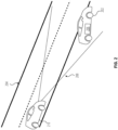
- FIG. 2 illustrates an example situation in which a disabled vehicle may utilize a waveform sensing, amplification and repeating system that can provide early warning functionality.
- disabled vehicle 202 may be next to, or obstructing, road 204.
- Disabled vehicle 202 may include the systems and sensors described with respect to FIG. 1 . Further, disabled vehicle 202 can provided the early warning functionality described with respect to FIG. 3 , FIG. 4 and/or FIG. 5 .
- disabled vehicle 202 may engage the warning functionality described herein as provided by warning system 206 (which can be, for example, responsive to cabin system 120). This may be accomplished automatically by one or more sensors within disabled vehicle 202, or manually be a passenger in disabled vehicle 202.
- warning system 206 which can be, for example, responsive to cabin system 120. This may be accomplished automatically by one or more sensors within disabled vehicle 202, or manually be a passenger in disabled vehicle 202.
- disabled vehicle 202 may receive radar signals 208 from remote vehicle 210.
- disabled vehicle 202 can use warning system 206 to modify received radar signals (e.g., radar signals 208) and transmit the modified radar signals back to remote vehicle 210, which can result in remote vehicle 210 taking sufficient precautions to safely navigate conditions caused by disabled vehicle 202.
- Disabled vehicle 202 can contemporaneously respond to multiple remote vehicles (e.g., 210).
- Various example techniques and architectures for providing the modified radar signals are discussed below with respect to FIG. 3 , FIG. 4 and FIG. 5 .
- Receiver RF front end 302 can function to receive high-frequency received radar signal 304 from remote sources (not illustrated in FIG. 3 ) via receiver antenna 306.
- High-frequency received radar signal 304 can be, for example, radar signals from an AV or radar signals from a vehicle having an ADAS.
- High-frequency received radar signal 304 received by receiver RF front end 302 are sent to receiver heterodyne mixer 308, which functions as a downmixer stage.
- receiver heterodyne mixer 308 converts high-frequency received radar signal 304 waveforms to lower-frequency baseband signal 310 for signal augmentation.
- lower-frequency baseband signal 310 can be between 20 MHz and 100 MHz.
- lower-frequency baseband signal 310 can be between 20 MHz to 4 GHz.
- the choice of frequencies for lower-frequency baseband signal 310 can depend on, for example, a radar waveform being used and/or other factors.
- Phase augmenter 312 is coupled to receive lower-frequency baseband signal 310 from receiver heterodyne mixer 308. Phase augmenter 312 is also coupled to receive emergency parameters 314, which can provide inputs on augmentation operations to be performed by phase augmenter 312. In one example, phase augmenter 312 can add a user defined phase (e.g., Doppler) offset to lower-frequency baseband signal 310 received from receiver heterodyne mixer 308. The phase offset is one type of parameter that can be included in emergency parameters 314. The additional information added to lower-frequency baseband signal 310 by phase augmenter 312, for example, phase offset can modify the output signal from the architecture of FIG. 3 sufficiently that a remote receiving vehicle (not illustrated in FIG. 3 ) will not consider the host vehicle an inactive element.
- phase augmenter 312 can add a user defined phase (e.g., Doppler) offset to lower-frequency baseband signal 310 received from receiver heterodyne mixer 308.
- the phase offset is one type of parameter that can be included in emergency parameters 314.
- Lower-frequency augmented signal 316 from phase augmenter 312 can be sent to transmitter up mixer 318 to convert lower-frequency augmented signal 316 from the lower frequency band to the original automotive radar band.
- both receiver heterodyne mixer 308 and transmitter up mixer 318 are coupled with, and utilize, local oscillator 320 to provide reference frequency information.
- High-frequency augmented signal 322 from transmitter up mixer 318 is sent to programmable amplifier 324 for amplification.
- programmable amplifier 324 is coupled to receive emergency parameters 314, which can indicate an amount of amplification to be provided by programmable amplifier 324.
- the amplification is a user-defined amount indicated by emergency parameters 314.
- High-frequency augmented signal 322 from programmable amplifier 324 is sent to transmitter RF front end 326 to be transmitted via transmitter antenna 328.
- the resulting transmitted waveform includes a distinguishable set of features to allow AVs and/or ADAS-equipped vehicles to acquire enough information to avoid a collision with the host vehicle and/or pedestrians associated with the host vehicle.
- the nature of the transmitted waveform allows the system to operate effectively in adverse weather conditions and low-light scenarios with minimal or no performance degradation.
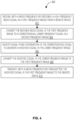
- Figure 4 is an example technique that can provide control of waveform sensing, amplification and repeating to provide early warning functionality.
- the following functionality 400 can be provided via, for example, the architectures of FIG. 1 and FIG. 3 .
- a radio frequency (RF) receiver receives a high-frequency radio signal in a first frequency range from a remote device.
- the first frequency range can correspond to an automotive radar range. In other examples different frequency ranges can be supported.
- the RF receiver can be part of a control system of an autonomous vehicle (AV). In other examples, the RF receiver can be part of a driver assistance system of a human-operated vehicle.
- AV autonomous vehicle
- the received high-frequency radio signal is converted from the first frequency range to a corresponding lower-frequency signal in a second frequency range by, for example, a heterodyne mixer (e.g., receiver heterodyne mixer 308).
- a heterodyne mixer e.g., receiver heterodyne mixer 308
- Various frequency ranges can be supported for the lower-frequency signal.
- the second frequency range can be 20 MHz to 100 MHz.
- the second frequency range can be 20 MHz to 4 GHz.
- phase information in the lower-frequency signal is modified (e.g., by phase augmenter 312) to generate a modified signal in the lower frequency range.
- a phase shift is added to the lower-frequency signal to simulate a low-velocity movement of the host vehicle.
- different phase modifications can be utilized.
- the phase modification can prevent the response signal transmitted by the host vehicle from being filtered out by the receiving vehicle. For example, some ADAS radars filter out responses that correspond to stationary objects. Such filtering could cause the host vehicle to "disappear" from the remote vehicle radar.
- the phase-modified signal in the lower frequency range is converted back to the higher first frequency range.
- the phase-modified high-frequency signal can provide the appearance of low-velocity movement of the host vehicle. Because the phase-modified high-frequency signal mimics a a slow-moving vehicle, the receiving vehicle can take appropriate evasive actions to avoid a collision with the host vehicle or with pedestrians associated with the host vehicle.
- Figure 5 is a block diagram of one example of a processing system that can provide control of waveform sensing, amplification and repeating to provide early warning functionality.
- system 512 can be part of an autonomous vehicle (e.g., autonomous vehicle 102 as part of internal computing system 124) that utilizes various sensors including radar sensors.
- system 512 can be part of a human-operated vehicle having an advanced driver assistance system (ADAS) that can utilized various sensors including radar sensors.
- ADAS advanced driver assistance system
- system 512 can include processor(s) 514 and non-transitory computer readable storage medium 516.
- Non-transitory computer readable storage medium 516 may store instructions 502, 504, 506, 508 and 410 that, when executed by processor(s) 514, cause processor(s) 514 to perform various functions.
- Examples of processor(s) 514 may include a microcontroller, a microprocessor, a central processing unit (CPU), a graphics processing unit (GPU), a data processing unit (DPU), an application-specific integrated circuit (ASIC), an field programmable gate array (FPGA), a system on a chip (SoC), etc.
- Examples of a non-transitory computer readable storage medium 516 include tangible media such as random access memory (RAM), read-only memory (ROM), electrically erasable programmable read-only memory (EEPROM), flash memory, a hard disk drive, etc.
- Instructions 502 cause processor(s) 514 to control a radio frequency (RF) receiver (e.g., receiver RF front end 302) to receive a high-frequency radio signal in a first frequency range (e.g., automotive radar range) from a remote device.
- RF radio frequency
- the received high-frequency radio signal can be sent to a heterodyne mixer.
- Instructions 504 cause processor(s) 514 to control the heterodyne mixer (e.g., receiver heterodyne mixer 308) to convert the received high-frequency radio signal the first frequency range to a corresponding lower-frequency signal in a second frequency range.
- the heterodyne mixer e.g., receiver heterodyne mixer 308
- the second frequency range can be 20 MHz to 100 MHz.
- the second frequency range can be 20 MHz to 4 GHz.
- Instructions 506 cause processor(s) 514 to control a phase augmenter (e.g., phase augmenter 312) to modify/augment phase information in the lower-frequency signal to generate a modified signal in the lower frequency range.
- a phase shift is added to the lower-frequency signal to simulate a low-velocity movement of the host vehicle.
- different phase modifications can be utilized.
- Instructions 508 cause processor(s) 514 to control an upmixer (e.g., transmitter up mixer 318) to convert the phase-modified signal in the lower frequency range to the higher, first frequency range.
- the resulting phase-modified high-frequency signal can provide the appearance of low-velocity movement of the host vehicle.
- Instructions 510 cause processor(s) 514 to control a transmitter (e.g., transmitter RF front end 326) to transmit the phase-modified high-frequency signal to the remote vehicle from which the original signal as received.
- a transmitter e.g., transmitter RF front end 326
- a method is performed by a radio detection and ranging (RADAR) system (110, 112) of a vehicle, the method comprising receiving, with a receiver radio frequency (RF) front end (302), a high-frequency radio signal (304) in a first frequency range, converting the received high-frequency radio signal (304) to a corresponding signal (310) in a second frequency range that is lower than the first frequency range, modifying, with a phase augmenter circuit (312), signal phase information in the corresponding signal to generate a lower-frequency augmented signal (316) in the second frequency range, converting the lower-frequency augmented signal (316) in the second frequency range to the first frequency range to generate a high-frequency augmented signal (322), and transmitting, with a transmitter radio frequency (RF) front end (326), the high-frequency augmented signal (322) in the first frequency range.
- RF radio frequency
- the modification to the signal phase information by the phase augmenter circuit (312) is based on one or more emergency parameters (314) and cause an indication of movement of the vehicle.
- a programmable amplifier (324) amplifies the modified signal (322) in the first frequency range.
- the vehicle comprises an autonomous vehicle.
- a system comprises a receiver radio frequency (RF) front end (302) to receive a radio signal from a remote source, a phase augmenter circuit (312) coupled with the receiver RF front end (302) to modify signal phase information in the received radio signal (304) based on one or more emergency parameters (314) to generate a modified signal (316) in response to a detected emergency condition, and a transmitter radio frequency (RF) front end (326) coupled with the phase augmenter circuit (312) to transmit the modified signal (322).
- RF radio frequency
- the system further comprises a receiver heterodyne mixer (308) coupled with the receiver RF front end (302) and with the phase augmenter circuit (312), the receiver heterodyne mixer (308) to convert the received radio signal (304) from a radio detection and ranging (RADAR) range to a lower baseband range, wherein the phase augmenter circuit (312) modifies signal phase information in the lower baseband range to generate the modified signal (316), a transmitter up mixer (318) coupled with the phase augmenter circuit (312) to convert the modified signal (316) from the lower baseband range to the RADAR range, a programmable amplifier (324) coupled with the transmitter up mixer (318) and to receive one or more pre-selected amplification parameters, the programmable amplifier (324) to amplify the modified signal (322) based on the received one or more pre-selected amplification parameters.
- RADAR radio detection and ranging
- the emergency condition corresponds to a host autonomous vehicle.
- the modification to the signal phase information indicates movement of a host vehicle.
- a radio detection and ranging (RADAR) system (110, 112) comprises means for receiving, with a receiver radio frequency (RF) front end (302), a high-frequency radio signal (304) in a first frequency range, means for converting the received high-frequency radio signal (304) to a corresponding signal (310) in a second frequency range that is lower than the first frequency range, means for modifying, with a phase augmenter circuit (312), signal phase information in the corresponding signal to generate a lower-frequency augmented signal (316) in the second frequency range, means for converting the lower-frequency augmented signal (316) in the second frequency range to the first frequency range to generate a high-frequency augmented signal (322), and means for transmitting, with a transmitter radio frequency (RF) front end (326), the high-frequency augmented signal (322) in the first frequency range.
- RF radio frequency
- the modification to the signal phase information by the phase augmenter circuit (312) is performed in response to detection of an emergency condition within an autonomous vehicle (102).
- the RADAR system further causes a programmable amplifier (324) to amplify the modified signal (322) in the first frequency range.
- Various examples may include various processes. These processes may be performed by hardware components or may be embodied in computer program or machine-executable instructions, which may be used to cause processor or logic circuits programmed with the instructions to perform the processes. Alternatively, the processes may be performed by a combination of hardware and software.
- Portions of various examples may be provided as a computer program product, which may include a non-transitory computer-readable medium having stored thereon computer program instructions, which may be used to program a computer (or other electronic devices) for execution by one or more processors to perform a process according to certain examples.
- the computer-readable medium may include, but is not limited to, magnetic disks, optical disks, read-only memory (ROM), random access memory (RAM), erasable programmable read-only memory (EPROM), electrically-erasable programmable read-only memory (EEPROM), magnetic or optical cards, flash memory, or other type of computer-readable medium suitable for storing electronic instructions.
- non-transitory computer readable storage medium 516 has stored thereon data representing sequences of instructions that, when executed by a processor(s) 514, cause the processor(s) 514 to perform certain operations.
- An example is an example or example.
- Reference in the specification to "an example,” “one example,” “some examples,” or “other examples” means that a particular feature, structure, or characteristic described in connection with the examples is included in at least some examples, but not necessarily all examples. Additionally, such feature, structure, or characteristics described in connection with “an example,” “one example,” “some examples,” or “other examples” should not be construed to be limited or restricted to those example(s), but may be, for example, combined with other examples.
- the various appearances of "an example,” “one example,” or “some examples” are not necessarily all referring to the same examples.
Landscapes
- Engineering & Computer Science (AREA)
- Radar, Positioning & Navigation (AREA)
- Remote Sensing (AREA)
- Physics & Mathematics (AREA)
- Computer Networks & Wireless Communication (AREA)
- General Physics & Mathematics (AREA)
- Electromagnetism (AREA)
- Radar Systems Or Details Thereof (AREA)
- Traffic Control Systems (AREA)
Abstract
Description
- This application claims the benefit of
US Application No. 17/560,428, filed on December 23, 2021 - Automobiles and other transportation platforms (e.g., trucks, boats, barges) generally include multiple lights that, among other things, allow other vehicles, or operators of the other vehicles, to more easily locate and identify vehicles in their operating environment. However, traditional lighting-based mechanisms suffer from limited range and other shortcomings.
- To easily identify the discussion of any particular element or act, the most significant digit or digits in a reference number refer to the figure number in which that element is first introduced.
-
FIG. 1 is a block diagram of an example autonomous vehicle. -
FIG. 2 illustrates an example situation in which a disabled vehicle may utilize a waveform sensing, amplification and repeating system that can provide early warning functionality. -
FIG. 3 is a block diagram of an example waveform sensing, amplification and repeating system that can provide early warning functionality. -
FIG. 4 is an example technique that can provide control of waveform sensing, amplification and repeating to provide early warning functionality. -
FIG. 5 is a block diagram of one example of a processing system that can provide control of waveform sensing, amplification and repeating to provide early warning functionality. - The components and techniques described herein can be used, for example, with an automobile as a roadside incident safety mechanism. Conceptually, the mechanisms described herein function as a warning beacon in a similar manner that flashing hazard lights on a vehicle serve as a warning signal. In various examples, a vehicle radiates an emergency signal that can notify other vehicles having automotive radar that the radiating vehicle is under distress and/or is stationary or moving at a lower than expected speed. As described in greater detail below, the described safety mechanisms can function in all-weather and/or lighting conditions and can provide a greater range than light-based systems.
- Vehicles (autonomous or human-operated) occasionally experience significant malfunctions and must park on the side of a road. The disabled vehicle could also be obstructing a roadway. This can be a dangerous situation for passengers (if any) in the disabled vehicle as well as for non-disabled vehicles traveling along the road. For example, at high speeds it may be difficult for a vehicle operator (automated or human) to detect a vehicle and/or a pedestrian on the side of the road. This can be exacerbated by bad weather and/or lighting conditions (e.g., dusk, fog, rain). As another example, a disabled vehicle may cause confusion for a vehicle operator (automated or human) because the presence of the disabled vehicle can be unexpected. This can lead to overcorrections or other reactions can cause accidents or other unsafe conditions.
- In various examples described below, a radar waveform sensing, amplification and repeating architecture is provided that can provide the emission of an extreme early warning signal that can provide vehicles a much earlier (and possibly more informational) notification as compared to current light-based systems. In some examples, the architecture can provide range and/or speed information about a vehicle in a disabled or distressed condition.
-
Figure 1 is a block diagram of an example autonomous vehicle. Autonomous vehicle 102 has the functionality to navigate roads without a human driver by utilizingsensors 104 and autonomous vehicle control systems 106. - Autonomous vehicle 102 can include, for example,
sensor systems 108 including any number of sensor systems (e.g.,sensor system 110, sensor system 112).Sensor systems 108 can include various types of sensors that can be arranged throughout autonomous vehicle 102. For example,sensor system 110 can be a camera sensor system. As another example,sensor system 112 can be a light detection and ranging (LIDAR) sensor system. As a further example, one ofsensor systems 108 can be a radio detection and ranging (RADAR) sensor system, an electromagnetic detection and ranging (EmDAR) sensor system, a sound navigation and ranging (SONAR) sensor system, a sound detection and ranging (SODAR) sensor system, a global navigation satellite system (GNSS) receiver system, a global positioning system (GPS) receiver system, accelerometers, gyroscopes, inertial measurement unit (IMU) systems, infrared sensor systems, laser rangefinder systems, microphones, etc. - Autonomous vehicle 102 can further include mechanical systems to control and manage operation of autonomous vehicle 102. For example, the mechanical systems can include
vehicle propulsion system 114,braking system 116,steering system 118,cabin system 120 andsafety system 122.Vehicle propulsion system 114 can include, for example, an electric motor, an internal combustion engine, or both.Braking system 116 can include an engine brake, brake pads, actuators and/or other components to control deceleration of autonomous vehicle 102.Steering system 118 can include components that control the direction of autonomous vehicle 102.Cabin system 120 can include, for example, cabin temperature control systems, in-cabin infotainment systems and other internal elements. -
Safety system 122 can include various lights, signal indicators, airbags, systems that detect and react to other vehicles. In the examples that follow,safety system 122 can include a waveform sensing, amplification and repeating system that can provide early warning functionality. In the examples that follow,safety system 122 can function to modify received radar signals that have been transmitted by other vehicles. - Automobiles can utilize different types of radar systems, for example, long-range radar (LRR), mid-range radar (MRR) and/or short-range radar (SRR). LRR systems can be used, for example, to detect objects that are farther away (e.g., 200 meters, 300 meters) from the vehicle transmitting the signal. LRR systems typically operate in the 77 GHz band (e.g., 76-81 GHz). SRR systems can be used, for example, for blind spot detection or collision avoidance. SRR systems typically operate in the 24 GHz band. MRR systems can operate in either the 24 GHz band or the 77 GHz band. Other frequency bands can also be supported.
- Autonomous vehicle 102 can further include
internal computing system 124 that can interact withsensor systems 108 as well as the mechanical systems (e.g.,vehicle propulsion system 114,braking system 116,steering system 118,cabin system 120, safety system 122).Internal computing system 124 includes at least one processor and at least one memory system that can store executable instructions to be executed by the processor.Internal computing system 124 can include any number of computing sub-systems that can function to control autonomous vehicle 102.Internal computing system 124 can receive inputs from passengers and/or human drivers within autonomous vehicle 102. -
Internal computing system 124 can includecontrol service 126, which functions to control operation of autonomous vehicle 102 via, for example, the mechanical systems as well as interacting withsensor systems 108.Control service 126 can interact with other systems (e.g.,constraint service 128,communication service 130,latency service 132, user interface service 134) to control operation of autonomous vehicle 102. -
Internal computing system 124 can also includeconstraint service 128, which functions to control operation of autonomous vehicle 102 through application of rule-based restrictions or other constraints on operation of autonomous vehicle 102.Constraint service 128 can interact with other systems (e.g.,control service 126,communication service 130,latency service 132, user interface service 134) to control operation of autonomous vehicle 102. -
Internal computing system 124 can further includecommunication service 130, which functions to control transmission of signals from, and receipt of signals by, autonomous vehicle 102.Communication service 130 can interact withsafety system 122 to provide the waveform sensing, amplification and repeating functionality described herein.Communication service 130 can interact with other systems (e.g.,control service 126,constraint service 128,latency service 132, user interface service 134) to control operation of autonomous vehicle 102. -
Internal computing system 124 can also includelatency service 132, which functions to provide and/or utilize timestamp information on communications to help manage and coordinate time-sensitive operations withininternal computing system 124 and autonomous vehicle 102. Thus,latency service 132 can interact with other systems (e.g.,control service 126,constraint service 128,communication service 130, user interface service 134) to control operation of autonomous vehicle 102. -
Internal computing system 124 can further include user interface service 134, which functions to provide information to, and receive inputs from, human passengers within autonomous vehicle 102. This can include, for example, receiving a desired destination for one or more passengers and providing status and timing information with respect to arrival at the desired destination. User interface service 134 can interact with other systems (e.g.,control service 126,constraint service 128,communication service 130, latency service 132) to control operation of autonomous vehicle 102. -
Internal computing system 124 can function to send and receive signals from autonomous vehicle 102 regarding reporting data for training and evaluating machine learning algorithms, requesting assistance from a remote computing system or a human operator, software updates, rideshare information (e.g., pickup, dropoff), etc. - As discussed in greater detail below, if autonomous vehicle 102 becomes disabled (e.g., engine/motor malfunction, flat tire, collision)
internal computing system 124,safety system 122 and/or other components of autonomous vehicle 102 can utilize an early warning signaling system that can modify radar signals received from other vehicles. -
Figure 2 illustrates an example situation in which a disabled vehicle may utilize a waveform sensing, amplification and repeating system that can provide early warning functionality. In the example ofFIG. 2 ,disabled vehicle 202 may be next to, or obstructing,road 204.Disabled vehicle 202 may include the systems and sensors described with respect toFIG. 1 . Further,disabled vehicle 202 can provided the early warning functionality described with respect toFIG. 3 ,FIG. 4 and/orFIG. 5 . - In response to becoming disabled,
disabled vehicle 202 may engage the warning functionality described herein as provided by warning system 206 (which can be, for example, responsive to cabin system 120). This may be accomplished automatically by one or more sensors withindisabled vehicle 202, or manually be a passenger indisabled vehicle 202. - After engaging the warning functionality,
disabled vehicle 202 may receiveradar signals 208 fromremote vehicle 210. In response to receivingradar signals 208,disabled vehicle 202 can usewarning system 206 to modify received radar signals (e.g., radar signals 208) and transmit the modified radar signals back toremote vehicle 210, which can result inremote vehicle 210 taking sufficient precautions to safely navigate conditions caused bydisabled vehicle 202.Disabled vehicle 202 can contemporaneously respond to multiple remote vehicles (e.g., 210). Various example techniques and architectures for providing the modified radar signals are discussed below with respect toFIG. 3 ,FIG. 4 andFIG. 5 . -
Figure 3 is a block diagram of an example waveform sensing, amplification and repeating system that can provide early warning functionality. In various examples, the system ofFIG. 3 can augment radio frequency (RF) signals (e.g., radar signals) received from other vehicles (e.g., radar signals 208) to provide a distinguishable set of features to allow a remote automated driving system (e.g, 210), or an advanced driver assistance system (ADAS), enough information to avoid a collision. The example system ofFIG. 3 can be part of, for example, an autonomous vehicle (AV) as illustrated inFIG. 1 and can be part of, for example,warning system 206. - Receiver RF
front end 302 can function to receive high-frequency receivedradar signal 304 from remote sources (not illustrated inFIG. 3 ) viareceiver antenna 306. High-frequency receivedradar signal 304 can be, for example, radar signals from an AV or radar signals from a vehicle having an ADAS. High-frequency receivedradar signal 304 received by receiver RFfront end 302 are sent to receiverheterodyne mixer 308, which functions as a downmixer stage. Thus,receiver heterodyne mixer 308 converts high-frequency receivedradar signal 304 waveforms to lower-frequency baseband signal 310 for signal augmentation. - The example downmixer architecture of
FIG. 3 allows the architecture ofFIG. 3 to be waveform agnostic and process any type of radar waveform. In one example, lower-frequency baseband signal 310 can be between 20 MHz and 100 MHz. As another example, lower-frequency baseband signal 310 can be between 20 MHz to 4 GHz. The choice of frequencies for lower-frequency baseband signal 310 can depend on, for example, a radar waveform being used and/or other factors. -
Phase augmenter 312 is coupled to receive lower-frequency baseband signal 310 from receiverheterodyne mixer 308.Phase augmenter 312 is also coupled to receiveemergency parameters 314, which can provide inputs on augmentation operations to be performed byphase augmenter 312. In one example,phase augmenter 312 can add a user defined phase (e.g., Doppler) offset to lower-frequency baseband signal 310 received from receiverheterodyne mixer 308. The phase offset is one type of parameter that can be included inemergency parameters 314. The additional information added to lower-frequency baseband signal 310 byphase augmenter 312, for example, phase offset can modify the output signal from the architecture ofFIG. 3 sufficiently that a remote receiving vehicle (not illustrated inFIG. 3 ) will not consider the host vehicle an inactive element. - Lower-frequency
augmented signal 316 fromphase augmenter 312 can be sent to transmitter upmixer 318 to convert lower-frequencyaugmented signal 316 from the lower frequency band to the original automotive radar band. In one example, both receiverheterodyne mixer 308 and transmitter upmixer 318 are coupled with, and utilize,local oscillator 320 to provide reference frequency information. - High-frequency
augmented signal 322 from transmitter upmixer 318 is sent toprogrammable amplifier 324 for amplification. In one example,programmable amplifier 324 is coupled to receiveemergency parameters 314, which can indicate an amount of amplification to be provided byprogrammable amplifier 324. In one example, the amplification is a user-defined amount indicated byemergency parameters 314. - High-frequency
augmented signal 322 fromprogrammable amplifier 324 is sent to transmitter RFfront end 326 to be transmitted viatransmitter antenna 328. Thus, the resulting transmitted waveform includes a distinguishable set of features to allow AVs and/or ADAS-equipped vehicles to acquire enough information to avoid a collision with the host vehicle and/or pedestrians associated with the host vehicle. The nature of the transmitted waveform allows the system to operate effectively in adverse weather conditions and low-light scenarios with minimal or no performance degradation. -
Figure 4 is an example technique that can provide control of waveform sensing, amplification and repeating to provide early warning functionality. In response to a vehicle operator (automated or human) activating a warning system, the followingfunctionality 400 can be provided via, for example, the architectures ofFIG. 1 andFIG. 3 . - In
block 402, a radio frequency (RF) receiver (e.g., receiver RF front end 302) receives a high-frequency radio signal in a first frequency range from a remote device. In one example, the first frequency range can correspond to an automotive radar range. In other examples different frequency ranges can be supported. In one example, the RF receiver can be part of a control system of an autonomous vehicle (AV). In other examples, the RF receiver can be part of a driver assistance system of a human-operated vehicle. - In
block 404, the received high-frequency radio signal is converted from the first frequency range to a corresponding lower-frequency signal in a second frequency range by, for example, a heterodyne mixer (e.g., receiver heterodyne mixer 308). Various frequency ranges can be supported for the lower-frequency signal. In one example, the second frequency range can be 20 MHz to 100 MHz. As another example, the second frequency range can be 20 MHz to 4 GHz. - In
block 406, phase information in the lower-frequency signal is modified (e.g., by phase augmenter 312) to generate a modified signal in the lower frequency range. In one example, a phase shift is added to the lower-frequency signal to simulate a low-velocity movement of the host vehicle. In other examples, different phase modifications can be utilized. The phase modification can prevent the response signal transmitted by the host vehicle from being filtered out by the receiving vehicle. For example, some ADAS radars filter out responses that correspond to stationary objects. Such filtering could cause the host vehicle to "disappear" from the remote vehicle radar. - In
block 408, the phase-modified signal in the lower frequency range is converted back to the higher first frequency range. Thus, the phase-modified high-frequency signal can provide the appearance of low-velocity movement of the host vehicle. Because the phase-modified high-frequency signal mimics a a slow-moving vehicle, the receiving vehicle can take appropriate evasive actions to avoid a collision with the host vehicle or with pedestrians associated with the host vehicle. - In
block 410, the phase-modified high-frequency signal in the first frequency range is transmitted to the remote device. Because the signaling provided is in the automotive radar range, the functionality described can function effectively in many weather conditions as well as low-visibility conditions. Further, because the received signal and the transmitted signal are in the automotive radar range, the functionality is compatible with many (if not all) current automotive radar systems without the need for modification. -
Figure 5 is a block diagram of one example of a processing system that can provide control of waveform sensing, amplification and repeating to provide early warning functionality. In one example,system 512 can be part of an autonomous vehicle (e.g., autonomous vehicle 102 as part of internal computing system 124) that utilizes various sensors including radar sensors. In other examples,system 512 can be part of a human-operated vehicle having an advanced driver assistance system (ADAS) that can utilized various sensors including radar sensors. - In an example,
system 512 can include processor(s) 514 and non-transitory computerreadable storage medium 516. Non-transitory computerreadable storage medium 516 may storeinstructions readable storage medium 516 include tangible media such as random access memory (RAM), read-only memory (ROM), electrically erasable programmable read-only memory (EEPROM), flash memory, a hard disk drive, etc. -
Instructions 502 cause processor(s) 514 to control a radio frequency (RF) receiver (e.g., receiver RF front end 302) to receive a high-frequency radio signal in a first frequency range (e.g., automotive radar range) from a remote device. The received high-frequency radio signal can be sent to a heterodyne mixer. -
Instructions 504 cause processor(s) 514 to control the heterodyne mixer (e.g., receiver heterodyne mixer 308) to convert the received high-frequency radio signal the first frequency range to a corresponding lower-frequency signal in a second frequency range. Various frequency ranges can be supported for the lower-frequency signal. In one example, the second frequency range can be 20 MHz to 100 MHz. As another example, the second frequency range can be 20 MHz to 4 GHz. -
Instructions 506 cause processor(s) 514 to control a phase augmenter (e.g., phase augmenter 312) to modify/augment phase information in the lower-frequency signal to generate a modified signal in the lower frequency range. In one example, a phase shift is added to the lower-frequency signal to simulate a low-velocity movement of the host vehicle. In other examples, different phase modifications can be utilized. -
Instructions 508 cause processor(s) 514 to control an upmixer (e.g., transmitter up mixer 318) to convert the phase-modified signal in the lower frequency range to the higher, first frequency range. The resulting phase-modified high-frequency signal can provide the appearance of low-velocity movement of the host vehicle. -
Instructions 510 cause processor(s) 514 to control a transmitter (e.g., transmitter RF front end 326) to transmit the phase-modified high-frequency signal to the remote vehicle from which the original signal as received. - In an example, a method is performed by a radio detection and ranging (RADAR) system (110, 112) of a vehicle, the method comprising receiving, with a receiver radio frequency (RF) front end (302), a high-frequency radio signal (304) in a first frequency range, converting the received high-frequency radio signal (304) to a corresponding signal (310) in a second frequency range that is lower than the first frequency range, modifying, with a phase augmenter circuit (312), signal phase information in the corresponding signal to generate a lower-frequency augmented signal (316) in the second frequency range, converting the lower-frequency augmented signal (316) in the second frequency range to the first frequency range to generate a high-frequency augmented signal (322), and transmitting, with a transmitter radio frequency (RF) front end (326), the high-frequency augmented signal (322) in the first frequency range.
- In another example, the modification to the signal phase information by the phase augmenter circuit (312) is performed in response to detection of an emergency condition within an autonomous vehicle (102).
- In another example, the modification to the signal phase information by the phase augmenter circuit (312) is based on one or more emergency parameters (314) and cause an indication of movement of the vehicle.
- In another example, a programmable amplifier (324) amplifies the modified signal (322) in the first frequency range.
- In another example, the vehicle comprises an autonomous vehicle.
- In another example, a system comprises a receiver radio frequency (RF) front end (302) to receive a radio signal from a remote source, a phase augmenter circuit (312) coupled with the receiver RF front end (302) to modify signal phase information in the received radio signal (304) based on one or more emergency parameters (314) to generate a modified signal (316) in response to a detected emergency condition, and a transmitter radio frequency (RF) front end (326) coupled with the phase augmenter circuit (312) to transmit the modified signal (322).
- In another example, the system further comprises a receiver heterodyne mixer (308) coupled with the receiver RF front end (302) and with the phase augmenter circuit (312), the receiver heterodyne mixer (308) to convert the received radio signal (304) from a radio detection and ranging (RADAR) range to a lower baseband range, wherein the phase augmenter circuit (312) modifies signal phase information in the lower baseband range to generate the modified signal (316), a transmitter up mixer (318) coupled with the phase augmenter circuit (312) to convert the modified signal (316) from the lower baseband range to the RADAR range, a programmable amplifier (324) coupled with the transmitter up mixer (318) and to receive one or more pre-selected amplification parameters, the programmable amplifier (324) to amplify the modified signal (322) based on the received one or more pre-selected amplification parameters.
- In another example, the emergency condition corresponds to a host autonomous vehicle.
- In another example, the modification to the signal phase information indicates movement of a host vehicle.
- In another example, the signal augmentation agent adds a user-defined phase offset to the received radio signal.
- In another example, a radio detection and ranging (RADAR) system (110, 112) comprises means for receiving, with a receiver radio frequency (RF) front end (302), a high-frequency radio signal (304) in a first frequency range, means for converting the received high-frequency radio signal (304) to a corresponding signal (310) in a second frequency range that is lower than the first frequency range, means for modifying, with a phase augmenter circuit (312), signal phase information in the corresponding signal to generate a lower-frequency augmented signal (316) in the second frequency range, means for converting the lower-frequency augmented signal (316) in the second frequency range to the first frequency range to generate a high-frequency augmented signal (322), and means for transmitting, with a transmitter radio frequency (RF) front end (326), the high-frequency augmented signal (322) in the first frequency range.
- In another example, the modification to the signal phase information by the phase augmenter circuit (312) is performed in response to detection of an emergency condition within an autonomous vehicle (102).
- In another example, the modification to the signal phase information by the phase augmenter circuit (312) is based on one or more emergency parameters (314) and cause an indication of movement of the vehicle.
- In another example, the RADAR system further causes a programmable amplifier (324) to amplify the modified signal (322) in the first frequency range.
- In the description above, for the purposes of explanation, numerous specific details are set forth in order to provide a thorough understanding of the described examples. It will be apparent, however, to one skilled in the art that examples may be practiced without some of these specific details. In other instances, well-known structures and devices are shown in block diagram form. There may be intermediate structures between illustrated components. The components described or illustrated herein may have additional inputs or outputs that are not illustrated or described.
- Various examples may include various processes. These processes may be performed by hardware components or may be embodied in computer program or machine-executable instructions, which may be used to cause processor or logic circuits programmed with the instructions to perform the processes. Alternatively, the processes may be performed by a combination of hardware and software.
- Portions of various examples may be provided as a computer program product, which may include a non-transitory computer-readable medium having stored thereon computer program instructions, which may be used to program a computer (or other electronic devices) for execution by one or more processors to perform a process according to certain examples. The computer-readable medium may include, but is not limited to, magnetic disks, optical disks, read-only memory (ROM), random access memory (RAM), erasable programmable read-only memory (EPROM), electrically-erasable programmable read-only memory (EEPROM), magnetic or optical cards, flash memory, or other type of computer-readable medium suitable for storing electronic instructions. Moreover, examples may also be downloaded as a computer program product, wherein the program may be transferred from a remote computer to a requesting computer. In some examples, non-transitory computer
readable storage medium 516 has stored thereon data representing sequences of instructions that, when executed by a processor(s) 514, cause the processor(s) 514 to perform certain operations. - An example is an example or example. Reference in the specification to "an example," "one example," "some examples," or "other examples" means that a particular feature, structure, or characteristic described in connection with the examples is included in at least some examples, but not necessarily all examples. Additionally, such feature, structure, or characteristics described in connection with "an example," "one example," "some examples," or "other examples" should not be construed to be limited or restricted to those example(s), but may be, for example, combined with other examples. The various appearances of "an example," "one example," or "some examples" are not necessarily all referring to the same examples.
Claims (15)
- A method performed by a radio detection and ranging (RADAR) system (110, 112) of a vehicle, the method comprising:receiving, with a receiver radio frequency (RF) front end (302), a high-frequency radio signal (304) in a first frequency range;converting the received high-frequency radio signal (304) to a corresponding signal (310) in a second frequency range that is lower than the first frequency range;modifying, with a phase augmenter circuit (312), signal phase information in the corresponding signal to generate a lower-frequency augmented signal (316) in the second frequency range;converting the lower-frequency augmented signal (316) in the second frequency range to the first frequency range to generate a high-frequency augmented signal (322);transmitting, with a transmitter radio frequency (RF) front end (326), the high-frequency augmented signal (322) in the first frequency range.
- The method of claim 1 wherein the modification to the signal phase information by the phase augmenter circuit (312) is performed in response to detection of an emergency condition within an autonomous vehicle (102).
- The method of claim 1 wherein the modification to the signal phase information by the phase augmenter circuit (312) is based on one or more emergency parameters (314) and cause an indication of movement of the vehicle.
- The method of claim 1 further comprising causing a programmable amplifier (324) to amplify the modified signal (322) in the first frequency range.
- The method of claim 1 wherein the vehicle comprises an autonomous vehicle.
- A system comprising:a receiver radio frequency (RF) front end (302) to receive a radio signal from a remote source;a phase augmenter circuit (312) coupled with the receiver RF front end (302) to modify signal phase information in the received radio signal (304) based on one or more emergency parameters (314) to generate a modified signal (316) in response to a detected emergency condition;a transmitter radio frequency (RF) front end (326) coupled with the phase augmenter circuit (312) to transmit the modified signal (322).
- The system of claim 6 further comprising:a receiver heterodyne mixer (308) coupled with the receiver RF front end (302) and with the phase augmenter circuit (312), the receiver heterodyne mixer (308) to convert the received radio signal (304) from a radio detection and ranging (RADAR) range to a lower baseband range, wherein the phase augmenter circuit (312) modifies signal phase information in the lower baseband range to generate the modified signal (316);a transmitter up mixer (318) coupled with the phase augmenter circuit (312) to convert the modified signal (316) from the lower baseband range to the RADAR range;a programmable amplifier (324) coupled with the transmitter up mixer (318) and to receive one or more pre-selected amplification parameters, the programmable amplifier (324) to amplify the modified signal (322) based on the received one or more pre-selected amplification parameters.
- The system of claim 7 wherein the emergency condition corresponds to a host autonomous vehicle.
- The system of claim 6 wherein the modification to the signal phase information indicates movement of a host vehicle.
- The system of claim 6 wherein the signal augmentation agent adds a user-defined phase offset to the received radio signal.
- A radio detection and ranging (RADAR) system (110, 112) comprising:means for receiving, with a receiver radio frequency (RF) front end (302), a high-frequency radio signal (304) in a first frequency range;means for converting the received high-frequency radio signal (304) to a corresponding signal (310) in a second frequency range that is lower than the first frequency range;means for modifying, with a phase augmenter circuit (312), signal phase information in the corresponding signal to generate a lower-frequency augmented signal (316) in the second frequency range;means for converting the lower-frequency augmented signal (316) in the second frequency range to the first frequency range to generate a high-frequency augmented signal (322);means for transmitting, with a transmitter radio frequency (RF) front end (326), the high-frequency augmented signal (322) in the first frequency range.
- The RADAR system of claim 11 wherein the modification to the signal phase information by the phase augmenter circuit (312) is performed in response to detection of an emergency condition within an autonomous vehicle (102).
- The RADAR system of claim 11 wherein the modification to the signal phase information by the phase augmenter circuit (312) is based on one or more emergency parameters (314) and cause an indication of movement of the vehicle.
- The RADAR system of claim 11 further comprising causing a programmable amplifier (324) to amplify the modified signal (322) in the first frequency range.
- A computer-readable storage medium including computer-readable instructions that, when executed, cause a computer to implement a method as claimed in any of claims 1-5.
Applications Claiming Priority (1)
| Application Number | Priority Date | Filing Date | Title |
|---|---|---|---|
| US17/560,428 US12111383B2 (en) | 2021-12-23 | 2021-12-23 | Radar signaling for emergency scenarios |
Publications (2)
| Publication Number | Publication Date |
|---|---|
| EP4202490A1 true EP4202490A1 (en) | 2023-06-28 |
| EP4202490B1 EP4202490B1 (en) | 2026-05-27 |
Family
ID=84359310
Family Applications (1)
| Application Number | Title | Priority Date | Filing Date |
|---|---|---|---|
| EP22207796.8A Active EP4202490B1 (en) | 2021-12-23 | 2022-11-16 | Radar signaling for emergency scenarios |
Country Status (2)
| Country | Link |
|---|---|
| US (1) | US12111383B2 (en) |
| EP (1) | EP4202490B1 (en) |
Cited By (1)
| Publication number | Priority date | Publication date | Assignee | Title |
|---|---|---|---|---|
| US12111383B2 (en) | 2021-12-23 | 2024-10-08 | Gm Cruise Holdings Llc | Radar signaling for emergency scenarios |
Citations (1)
| Publication number | Priority date | Publication date | Assignee | Title |
|---|---|---|---|---|
| DE102019008530A1 (en) * | 2019-12-09 | 2020-08-20 | Daimler Ag | Method for the improved detection of stationary or slowly moving vehicles |
Family Cites Families (45)
| Publication number | Priority date | Publication date | Assignee | Title |
|---|---|---|---|---|
| US3801979A (en) * | 1972-04-26 | 1974-04-02 | J Chisholm | Integrated collision avoidance, dme, telemetry, and synchronization system |
| US3864662A (en) * | 1973-05-18 | 1975-02-04 | France Etat | Telemetry systems employing active transponders |
| GB1500289A (en) * | 1974-06-03 | 1978-02-08 | Rca Corp | Homodyne communication system |
| US4068232A (en) * | 1976-02-12 | 1978-01-10 | Fairchild Industries, Inc. | Passive encoding microwave transponder |
| ATE98025T1 (en) * | 1987-07-31 | 1993-12-15 | Texas Instruments Deutschland | TRANSPONDER ARRANGEMENT. |
| US5451959A (en) * | 1988-07-08 | 1995-09-19 | Texas Instruments Deutschland Gmbh | Transponder arrangement |
| WO1991010290A1 (en) * | 1989-12-28 | 1991-07-11 | Kabushiki Kaisha Toyota Chuo Kenkyusho | Mobile communication system and mobile communication equipment |
| NL9002683A (en) * | 1990-12-06 | 1992-07-01 | Nedap Nv | RETRO-REFLECTIVE MICROWAVE TRANSPONDER. |
| US5387916A (en) * | 1992-07-31 | 1995-02-07 | Westinghouse Electric Corporation | Automotive navigation system and method |
| US5745049A (en) * | 1995-07-20 | 1998-04-28 | Yokogawa Electric Corporation | Wireless equipment diagnosis system |
| US5712628A (en) * | 1995-08-31 | 1998-01-27 | Northrop Grumman Corporation | Digitally programmable radio modules for transponder systems |
| US5847661A (en) * | 1996-03-15 | 1998-12-08 | Intelligent Ideation, Inc. | Vehicle data acquisition system |
| US5945938A (en) * | 1996-11-14 | 1999-08-31 | National University Of Singapore | RF identification transponder |
| US5825302A (en) * | 1996-11-20 | 1998-10-20 | Texas Instruments Incorporated | System and method for transmitting data using reflected electromagnetic radiation |
| SE508835C2 (en) * | 1996-11-26 | 1998-11-09 | Tagmaster Ab | transponder |
| US6107910A (en) * | 1996-11-29 | 2000-08-22 | X-Cyte, Inc. | Dual mode transmitter/receiver and decoder for RF transponder tags |
| JP4588220B2 (en) * | 1999-03-26 | 2010-11-24 | アイシス・イノベーション・リミテッド | transponder |
| US6963301B2 (en) * | 2002-08-19 | 2005-11-08 | G-Track Corporation | System and method for near-field electromagnetic ranging |
| JP3979246B2 (en) * | 2002-09-30 | 2007-09-19 | ブラザー工業株式会社 | Communication system interrogator and interrogator |
| US7683760B2 (en) * | 2005-03-01 | 2010-03-23 | I.D. Systems, Inc. | Mobile portal for RFID applications |
| US7221308B2 (en) * | 2005-04-19 | 2007-05-22 | Northrop Grumman Corporation | Joint stars embedded data link |
| US8466776B2 (en) * | 2010-07-01 | 2013-06-18 | The United States Of America As Represented By The Administrator Of The National Aeronautics And Space Administration | Extended range passive wireless tag system and method |
| DE102012211809A1 (en) * | 2012-07-06 | 2014-01-09 | Siemens Aktiengesellschaft | Method and arrangement for relative position detection of stations by means of radio location |
| US9612325B2 (en) * | 2014-06-02 | 2017-04-04 | Ensco, Inc. | Unwrapping and prediction of distance and velocity measurements using carrier signals |
| FI126136B (en) * | 2014-09-03 | 2016-07-15 | Metso Flow Control Oy | Integrated passive RFID transponder chip and passive RFID sensor tag |
| US9720080B1 (en) * | 2014-11-25 | 2017-08-01 | Sandia Corporation | Combined radar and telemetry system |
| US10422870B2 (en) * | 2015-06-15 | 2019-09-24 | Humatics Corporation | High precision time of flight measurement system for industrial automation |
| DE102015015036A1 (en) * | 2015-11-23 | 2017-05-24 | race result AG | Position tracking at sports events |
| WO2017120110A1 (en) * | 2016-01-06 | 2017-07-13 | Russell David Wayne | Utilization of national cellular infrastructure for uav command and control |
| US9954955B2 (en) * | 2016-04-25 | 2018-04-24 | Uhnder, Inc. | Vehicle radar system with a shared radar and communication system |
| US9931976B1 (en) * | 2016-10-05 | 2018-04-03 | Dell Products L.P. | Truck safety zone using a vehicle gateway |
| US20190080612A1 (en) * | 2017-09-14 | 2019-03-14 | Qualcomm Incorporated | Navigation techniques for autonomous and semi-autonomous vehicles |
| US11112498B2 (en) * | 2018-02-12 | 2021-09-07 | Magna Electronics Inc. | Advanced driver-assistance and autonomous vehicle radar and marking system |
| WO2020180077A1 (en) * | 2019-03-01 | 2020-09-10 | Lg Electronics Inc. | Joint frequency-and-phase modulation for multi-antenna backscatter vehicular position |
| US11275181B2 (en) * | 2019-05-15 | 2022-03-15 | Rtr Technologies | Radio frequency (RF) ranging in propagation limited RF environments utilizing aerial vehicles |
| US11754669B2 (en) * | 2019-09-30 | 2023-09-12 | Qualcomm Incorporated | Radar coordination for multi-radar coexistence |
| US12210109B2 (en) * | 2019-12-06 | 2025-01-28 | Lg Electronics Inc. | Method and apparatus for positioning using backscatter tag |
| JP2023513264A (en) * | 2020-02-10 | 2023-03-30 | パーセプティブ・インコーポレイテッド | Centralized object detection sensor network system |
| US11822003B2 (en) * | 2021-03-01 | 2023-11-21 | Qualcomm Incorporated | Methods and systems for adjusting radar parameters based on congestion measurements |
| US12442891B2 (en) * | 2021-04-28 | 2025-10-14 | Qualcomm Incorporated | Radar interference mitigation |
| US12369106B2 (en) * | 2021-09-23 | 2025-07-22 | Intel Corporation | Occupancy grid map computation, V2X complementary sensing, and coordination of cooperative perception data transmission in wireless networks |
| EP4170389A1 (en) * | 2021-10-22 | 2023-04-26 | Aptiv Services Poland S.A. | Methods and apparatuses for supporting vehicle-to-infrastructure, v2i, communication |
| EP4170284A1 (en) * | 2021-10-22 | 2023-04-26 | Aptiv Services Poland S.A. | Methods and devices for determining a position of a vehicle within a v2i infrastructure |
| US12481061B2 (en) * | 2021-12-16 | 2025-11-25 | Gm Cruise Holdings Llc | Frequency modulated continuous wave (FMCW) waveform generator/decoder |
| US12111383B2 (en) | 2021-12-23 | 2024-10-08 | Gm Cruise Holdings Llc | Radar signaling for emergency scenarios |
-
2021
- 2021-12-23 US US17/560,428 patent/US12111383B2/en active Active
-
2022
- 2022-11-16 EP EP22207796.8A patent/EP4202490B1/en active Active
Patent Citations (1)
| Publication number | Priority date | Publication date | Assignee | Title |
|---|---|---|---|---|
| DE102019008530A1 (en) * | 2019-12-09 | 2020-08-20 | Daimler Ag | Method for the improved detection of stationary or slowly moving vehicles |
Cited By (1)
| Publication number | Priority date | Publication date | Assignee | Title |
|---|---|---|---|---|
| US12111383B2 (en) | 2021-12-23 | 2024-10-08 | Gm Cruise Holdings Llc | Radar signaling for emergency scenarios |
Also Published As
| Publication number | Publication date |
|---|---|
| US20230204747A1 (en) | 2023-06-29 |
| EP4202490B1 (en) | 2026-05-27 |
| US12111383B2 (en) | 2024-10-08 |
Similar Documents
| Publication | Publication Date | Title |
|---|---|---|
| US11021172B2 (en) | System for controlling host vehicle and method for controlling host vehicle | |
| US12246714B2 (en) | Advanced driver assistance system, and vehicle having the same | |
| EP3196089B1 (en) | Vehicle safety assist system, vehicle comprising a vehicle safety assist system and a method for providing driver warning or performing autonomous braking | |
| JP4939564B2 (en) | Vehicle information providing device | |
| US11529967B2 (en) | Driver assistance apparatus and method of thereof | |
| US20170038466A1 (en) | Detection of an object by use of a 3d camera and a radar | |
| CN115616952A (en) | Sensor control method, device and sensor | |
| US8946990B1 (en) | Vehicle headlight detection system | |
| US20220113402A1 (en) | Apparatus, system, and method of processing point cloud radar information | |
| US12174293B2 (en) | Low phase noise radar system | |
| US20210025970A1 (en) | Electronic apparatus, control method for electronic apparatus, and control program for electronic apparatus | |
| EP4254380A1 (en) | Electronic apparatus, control method for electronic apparatus, and program | |
| US20210373151A1 (en) | Electronic device, control method of electronic device, and control program of electronic device | |
| US12111383B2 (en) | Radar signaling for emergency scenarios | |
| JP2025119434A (en) | Vehicle control device | |
| EP4230492B1 (en) | Determination device, determination method, and program | |
| US20190161007A1 (en) | Unilluminated vehicle indication based on communication | |
| JP7072665B2 (en) | Electronic devices, control methods for electronic devices, and control programs for electronic devices | |
| US12248063B2 (en) | Electronic device, method for controlling electronic device, and program for controlling electronic device | |
| Singh et al. | Review on vehicular radar for road safety | |
| US20220208005A1 (en) | Electronic device, method for controlling electronic device, and program | |
| EP4194884A1 (en) | Electronic device, method for controlling electronic device, and program | |
| JP2019066290A (en) | Radar device and method for detecting target | |
| CN118215612A (en) | Information processing method and device | |
| JP7843795B2 (en) | Control device, control method, and program |
Legal Events
| Date | Code | Title | Description |
|---|---|---|---|
| PUAI | Public reference made under article 153(3) epc to a published international application that has entered the european phase |
Free format text: ORIGINAL CODE: 0009012 |
|
| STAA | Information on the status of an ep patent application or granted ep patent |
Free format text: STATUS: THE APPLICATION HAS BEEN PUBLISHED |
|
| AK | Designated contracting states |
Kind code of ref document: A1 Designated state(s): AL AT BE BG CH CY CZ DE DK EE ES FI FR GB GR HR HU IE IS IT LI LT LU LV MC ME MK MT NL NO PL PT RO RS SE SI SK SM TR |
|
| P01 | Opt-out of the competence of the unified patent court (upc) registered |
Effective date: 20230628 |
|
| STAA | Information on the status of an ep patent application or granted ep patent |
Free format text: STATUS: REQUEST FOR EXAMINATION WAS MADE |
|
| 17P | Request for examination filed |
Effective date: 20231220 |
|
| RBV | Designated contracting states (corrected) |
Designated state(s): AL AT BE BG CH CY CZ DE DK EE ES FI FR GB GR HR HU IE IS IT LI LT LU LV MC ME MK MT NL NO PL PT RO RS SE SI SK SM TR |
|
| STAA | Information on the status of an ep patent application or granted ep patent |
Free format text: STATUS: EXAMINATION IS IN PROGRESS |
|
| 17Q | First examination report despatched |
Effective date: 20250127 |
|
| GRAP | Despatch of communication of intention to grant a patent |
Free format text: ORIGINAL CODE: EPIDOSNIGR1 |
|
| STAA | Information on the status of an ep patent application or granted ep patent |
Free format text: STATUS: GRANT OF PATENT IS INTENDED |
|
| INTG | Intention to grant announced |
Effective date: 20260107 |
|
| GRAS | Grant fee paid |
Free format text: ORIGINAL CODE: EPIDOSNIGR3 |
|
| GRAA | (expected) grant |
Free format text: ORIGINAL CODE: 0009210 |
|
| STAA | Information on the status of an ep patent application or granted ep patent |
Free format text: STATUS: THE PATENT HAS BEEN GRANTED |
|
| AK | Designated contracting states |
Kind code of ref document: B1 Designated state(s): AL AT BE BG CH CY CZ DE DK EE ES FI FR GB GR HR HU IE IS IT LI LT LU LV MC ME MK MT NL NO PL PT RO RS SE SI SK SM TR |
|
| REG | Reference to a national code |
Ref country code: CH Ref legal event code: F10 Free format text: ST27 STATUS EVENT CODE: U-0-0-F10-F00 (AS PROVIDED BY THE NATIONAL OFFICE) Effective date: 20260527 Ref country code: GB Ref legal event code: FG4D |
|
| REG | Reference to a national code |
Ref country code: DE Ref legal event code: R096 Ref document number: 602022037463 Country of ref document: DE |