EP4202298B1 - Burner module - Google Patents
Burner module Download PDFInfo
- Publication number
- EP4202298B1 EP4202298B1 EP22214828.0A EP22214828A EP4202298B1 EP 4202298 B1 EP4202298 B1 EP 4202298B1 EP 22214828 A EP22214828 A EP 22214828A EP 4202298 B1 EP4202298 B1 EP 4202298B1
- Authority
- EP
- European Patent Office
- Prior art keywords
- burner
- nozzles
- attachment
- plane
- modular
- Prior art date
- Legal status (The legal status is an assumption and is not a legal conclusion. Google has not performed a legal analysis and makes no representation as to the accuracy of the status listed.)
- Active
Links
Images
Classifications
-
- F—MECHANICAL ENGINEERING; LIGHTING; HEATING; WEAPONS; BLASTING
- F23—COMBUSTION APPARATUS; COMBUSTION PROCESSES
- F23D—BURNERS
- F23D14/00—Burners for combustion of a gas, e.g. of a gas stored under pressure as a liquid
- F23D14/46—Details
- F23D14/48—Nozzles
-
- F—MECHANICAL ENGINEERING; LIGHTING; HEATING; WEAPONS; BLASTING
- F23—COMBUSTION APPARATUS; COMBUSTION PROCESSES
- F23D—BURNERS
- F23D14/00—Burners for combustion of a gas, e.g. of a gas stored under pressure as a liquid
- F23D14/46—Details
- F23D14/48—Nozzles
- F23D14/58—Nozzles characterised by the shape or arrangement of the outlet or outlets from the nozzle, e.g. of annular configuration
-
- F—MECHANICAL ENGINEERING; LIGHTING; HEATING; WEAPONS; BLASTING
- F23—COMBUSTION APPARATUS; COMBUSTION PROCESSES
- F23D—BURNERS
- F23D14/00—Burners for combustion of a gas, e.g. of a gas stored under pressure as a liquid
- F23D14/46—Details
-
- F—MECHANICAL ENGINEERING; LIGHTING; HEATING; WEAPONS; BLASTING
- F23—COMBUSTION APPARATUS; COMBUSTION PROCESSES
- F23D—BURNERS
- F23D2900/00—Special features of, or arrangements for burners using fluid fuels or solid fuels suspended in a carrier gas
- F23D2900/14—Special features of gas burners
- F23D2900/14641—Special features of gas burners with gas distribution manifolds or bars provided with a plurality of nozzles
Definitions
- the present invention relates to a burner module, usable for example in a wall boiler.
- a burner module normally comprises a manifold for combustible gas.
- a manifold for combustible gas.
- Such a manifold is typically tubular in shape and essentially comprises a cylindrical conduit closed at the ends.
- the manifold is provided with a plurality of nozzles, i.e. calibrated openings that put the inside of the manifold in communication with the external environment.
- the nozzles are placed side by side with each other and are aligned along a generatrix of the outer surface of the manifold.
- a plurality of burner modules are juxtaposed one another to define a modular burner.
- the nozzles are intended to allow the emission of combustible gas outside the manifold, so that combustion can take place.
- the combustible gas which flows out of the collector through the nozzles, feeds the burner and the flame develops above the burner module.
- Additional comburent air called secondary air, is fed to the flame from the surrounding environment.
- Combustion products comprise, among other compounds, carbon monoxide (CO) and nitrogen oxides (NOx). These two compounds, as known, should be reduced as much as possible.
- the amount of CO and NOx produced by combustion depends on various parameters, including the ratio of fuel to primary air, as well as the amount of secondary air in relation to the flow rate emitted by the nozzles.
- a limited primary air supply results in a significant lowering of the lamba of the combustible air mixture.
- the flame temperature, in the sections closest to the flame diffuser is above the critical value for the formation of nitrogen oxides (NOx). This phenomenon is particularly accentuated towards low power regimes of the boiler and is certainly undesirable for obvious reasons tied to the containment of harmful emissions.
- the design of the burner module is therefore very important to achieve optimal combustion conditions, with low emissions of harmful compounds.
- the diameter of the nozzles, their number and the pitch of separation between them, the collector section must be chosen with extreme care in order to contain the emissions of harmful compounds.
- the current design is therefore relatively slow and laborious. Furthermore, in case of modifications required for one or more parameters of the burner module, it does not allow to readily adapt the other parameters for optimal operation.
- the object of the present invention is to offer a burner module that allows to obtain optimal operating conditions, with low emissions of harmful compounds, and that can be quickly designed according to different construction and/or installation needs.
- the burner module according to the present invention comprises a manifold (10), provided with a tubular body (11) that delimits an internal cavity (12).
- the manifold (10) is provided with an inlet opening (13), through which a combustible gas can be introduced into the tubular body (11).
- each nozzle comprises a threaded body (22), through which a calibrated through opening is obtained, at one end of which an outlet opening (21) of the nozzle (20) is arranged.
- the threaded body (22) is screwed into a corresponding through opening obtained through the wall of the tubular body (11).
- the outlet openings (21) have the same diameter (D).
- the outlet openings (21) of the nozzles (20) lie on a common emission plane (P).
- the nozzles (20) are aligned along a direction parallel to a longitudinal axis (X) of the tubular body (11).
- the nozzles (20) are space apart from one another by a constant pitch (P).
- This step (P) is substantially the distance separating the outlet openings (21) from each other.
- each outlet opening (21) is separated from the two adjacent openings by the pitch (P).
- the burner module also comprises a pair of brackets (30), provided to enable the attachment of the manifold (10) to a support structure, not shown.
- a support structure for example, is a suitable attachment element provided in a wall boiler or in a water heater or, in general, an attachment element provided in the device in which the burner module is installed.
- the brackets (30) are positioned at the ends of the tubular body (11).
- the brackets (30) have a joint portion (32), at which they are connected to the tubular body (11), closing the ends thereof.
- the brackets (30) also have an attachment portion (31), provided to enable the connection to said support structure of the device in which the installation of the burner module is envisaged.
- the attachment portions lie on the same connection plane (S), parallel to the emission plane (E).
- the attachment to said support structure is located on said connection plane.
- connection plane (S) and the emission plane (E) are spaced apart by a main height (H).
- main height (H) is the distance separating the connection plane (S) and the emission plane (P).
- R dimensional parameter
- the dimensional parameter (R) is given by the product between said main height (H), said pitch (P) and the diameter (D) of the outlet openings (21) of the nozzles (20).
- the dimensional parameter (R) is therefore a volume.
- nOx emissions remain well below 90 mg/kWh, and CO emissions remain well below 1000 ppm.
- the diameter of the outlet openings (21) which is typically a function of the type of fuel used and depends on the conformation of the nozzles (20), and the main height (H) being known, which depends on the position and on the installation required for the burner module, obtaining the optimal pitch (P) at which to place the nozzles (20) is immediate.
- the diameter of the openings (21) is comprised between about 0.9 and 1.5 mm, as a function of the operating pressure.
- the dimensional parameter (R) allows the optimal main height (H) to be obtained.
- said dimensional parameter (R) is comprised between 75 and 80, i.e.: 75 ⁇ R ⁇ 80 .
- NOx remains below 85mg/kWh, while CO remains below 800 ppm.
- a plurality of burner modules according to the present invention may be arranged to form a modular burner.
- the burner modules are arranged side by side with each other with the same emission plane (P) and the same connection plane (S).
- the modular burner comprises twenty-one burner modules.
- Examples of further particularly effective configurations for a modular burner comprising a plurality of burner modules according to the present invention, provide for nineteen or thirty-one burner modules. In all cases, the combustion conditions are optimal, with reduced emissions of harmful compounds.
- the burner module according to the present invention has important advantages over the prior art.
- the burner module allows to obtain optimal combustion conditions, containing the amount of harmful compounds emitted, in particular NOx and CO.
- the definition of the dimensional parameter (R) allows to greatly simplify the design of the burner module, ensuring the certainty of containing the amount of harmful compounds emitted, without the need to make prototypes to test the operation thereof.
Landscapes
- Engineering & Computer Science (AREA)
- Chemical & Material Sciences (AREA)
- Combustion & Propulsion (AREA)
- Mechanical Engineering (AREA)
- General Engineering & Computer Science (AREA)
- Gas Burners (AREA)
- Medicines Containing Material From Animals Or Micro-Organisms (AREA)
Description
- The present invention relates to a burner module, usable for example in a wall boiler.
- A burner module normally comprises a manifold for combustible gas. Such a manifold is typically tubular in shape and essentially comprises a cylindrical conduit closed at the ends.
- The manifold is provided with a plurality of nozzles, i.e. calibrated openings that put the inside of the manifold in communication with the external environment. The nozzles are placed side by side with each other and are aligned along a generatrix of the outer surface of the manifold.
- A plurality of burner modules are juxtaposed one another to define a modular burner.
- The nozzles are intended to allow the emission of combustible gas outside the manifold, so that combustion can take place. In particular, the combustible gas, which flows out of the collector through the nozzles, feeds the burner and the flame develops above the burner module. Additional comburent air, called secondary air, is fed to the flame from the surrounding environment.
- Combustion products comprise, among other compounds, carbon monoxide (CO) and nitrogen oxides (NOx). These two compounds, as known, should be reduced as much as possible.
- The amount of CO and NOx produced by combustion depends on various parameters, including the ratio of fuel to primary air, as well as the amount of secondary air in relation to the flow rate emitted by the nozzles. For example, a limited primary air supply results in a significant lowering of the lamba of the combustible air mixture. This means that the flame temperature, in the sections closest to the flame diffuser, is above the critical value for the formation of nitrogen oxides (NOx). This phenomenon is particularly accentuated towards low power regimes of the boiler and is certainly undesirable for obvious reasons tied to the containment of harmful emissions.
- The design of the burner module is therefore very important to achieve optimal combustion conditions, with low emissions of harmful compounds. In particular, the diameter of the nozzles, their number and the pitch of separation between them, the collector section, must be chosen with extreme care in order to contain the emissions of harmful compounds.
- Currently, the design of the burner modules is substantially done in an empirical manner, developing a model and testing the behaviour thereof during operation. In case of unsatisfactory behaviour, it is necessary to modify the model in one or more geometric parameters, for subsequent tests, until a satisfactory configuration is obtained. Each of
US1863100 ,US20190257253A1 , andEP3795899A1 discloses a burner module for a gaseous mixture according to the preamble of claim 1. - The current design is therefore relatively slow and laborious. Furthermore, in case of modifications required for one or more parameters of the burner module, it does not allow to readily adapt the other parameters for optimal operation.
- The object of the present invention is to offer a burner module that allows to obtain optimal operating conditions, with low emissions of harmful compounds, and that can be quickly designed according to different construction and/or installation needs.
- Features and advantages of the present invention will more fully emerge from the following detailed description of an embodiment of the present invention, as illustrated in a non-limiting example in the accompanying figures, in which:
-
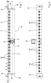
figure 1 shows a schematic view of the burner module according to the present invention, in vertical elevation; -
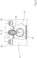
figure 2 shows a top view of the burner module offigure 1 ; -
figure 3 shows a sectional view on plane A-A offigure 2 . - The burner module according to the present invention comprises a manifold (10), provided with a tubular body (11) that delimits an internal cavity (12). The manifold (10) is provided with an inlet opening (13), through which a combustible gas can be introduced into the tubular body (11).
- A plurality of nozzles (20) are arranged so as to pass through the tubular body (11). In a manner known in the art, each nozzle comprises a threaded body (22), through which a calibrated through opening is obtained, at one end of which an outlet opening (21) of the nozzle (20) is arranged. The threaded body (22) is screwed into a corresponding through opening obtained through the wall of the tubular body (11). The outlet openings (21) have the same diameter (D).
- The outlet openings (21) of the nozzles (20) lie on a common emission plane (P). In particular, the nozzles (20) are aligned along a direction parallel to a longitudinal axis (X) of the tubular body (11). Furthermore, the nozzles (20) are space apart from one another by a constant pitch (P). This step (P) is substantially the distance separating the outlet openings (21) from each other. In practice, each outlet opening (21) is separated from the two adjacent openings by the pitch (P).
- The burner module also comprises a pair of brackets (30), provided to enable the attachment of the manifold (10) to a support structure, not shown. Such a support structure, for example, is a suitable attachment element provided in a wall boiler or in a water heater or, in general, an attachment element provided in the device in which the burner module is installed. Preferably, but not necessarily, the brackets (30) are positioned at the ends of the tubular body (11). In the embodiment depicted, the brackets (30) have a joint portion (32), at which they are connected to the tubular body (11), closing the ends thereof.
- The brackets (30) also have an attachment portion (31), provided to enable the connection to said support structure of the device in which the installation of the burner module is envisaged. The attachment portions lie on the same connection plane (S), parallel to the emission plane (E). The attachment to said support structure is located on said connection plane.
- The connection plane (S) and the emission plane (E) are spaced apart by a main height (H). In other words, the main height (H) is the distance separating the connection plane (S) and the emission plane (P).
- Following extensive research, the Applicant has identified a dimensional parameter (R) that is extremely relevant for the correct design of the burner module, i.e. for the containment of the compounds emitted by the combustion of the mixture.
- The dimensional parameter (R) is given by the product between said main height (H), said pitch (P) and the diameter (D) of the outlet openings (21) of the nozzles (20). The dimensional parameter (R) is therefore a volume.
- If the dimensions (H,P,D) whose product defines the dimensional parameter (R) are measured in millimetres, the Applicant has found that a value of (R) comprised between 71 and 84 mm3 allows NOx emissions to be contained well below 90 mg/kWh, and CO emissions to be contained well below 1000 ppm.
- In practice, if:


- nOx emissions remain well below 90 mg/kWh, and CO emissions remain well below 1000 ppm.
- Thanks to the identification of the dimensional parameter (R), the design of a burner module is considerably simplified.
- For example, given the diameter of the outlet openings (21), which is typically a function of the type of fuel used and depends on the conformation of the nozzles (20), and the main height (H) being known, which depends on the position and on the installation required for the burner module, obtaining the optimal pitch (P) at which to place the nozzles (20) is immediate. For example, in the case of natural gas, the diameter of the openings (21) is comprised between about 0.9 and 1.5 mm, as a function of the operating pressure.
- Conversely, if the conformation of the nozzles (20) requires a predetermined mounting pitch (P), the dimensional parameter (R) allows the optimal main height (H) to be obtained.
- Preferably, said dimensional parameter (R) is comprised between 75 and 80, i.e.:

- Within this range comprised between 75 and 80, NOx remains below 85mg/kWh, while CO remains below 800 ppm.
- A plurality of burner modules according to the present invention may be arranged to form a modular burner. The burner modules are arranged side by side with each other with the same emission plane (P) and the same connection plane (S). In a preferred embodiment, the modular burner comprises twenty-one burner modules.
- Examples of further particularly effective configurations for a modular burner, comprising a plurality of burner modules according to the present invention, provide for nineteen or thirty-one burner modules. In all cases, the combustion conditions are optimal, with reduced emissions of harmful compounds.
- The burner module according to the present invention has important advantages over the prior art.
- First of all, the burner module allows to obtain optimal combustion conditions, containing the amount of harmful compounds emitted, in particular NOx and CO.
- In addition, the definition of the dimensional parameter (R) allows to greatly simplify the design of the burner module, ensuring the certainty of containing the amount of harmful compounds emitted, without the need to make prototypes to test the operation thereof.
Claims (6)
- A burner module for a gaseous mixture, comprising:a manifold (10), provided with a tubular body (11) that delimits an internal cavity (12);a plurality of nozzles (20), arranged so as to pass through the tubular body (11), each of which has an outlet opening (21);an emission plane (P), on which the outlet openings (21) of the nozzles (12) lie;a pair of brackets (30), provided to enable the attachment of the manifold (10) to a support structure, and which have an attachment portion (31) for attaching to said support structure;a connection plane (S), on which the attachment portions (31) lie and on which the attachment to said support structure is located;wherein the outlet openings (21) of the nozzles have an equal diameter (D);wherein the nozzles (20) are spaced apart from one another by a constant pitch (P);wherein the connection plane (S) and the emission plane (P) are parallel to each other and are spaced apart by a main height (H);characterised in that:
a dimensional parameter (R) given by the product between said main height (H), said pitch (P) and the diameter (D) of the outlet openings (21) of the nozzles (20), measured in millimetres, is comprised between 71 and 84, i.e.:

- The burner module according to claim 1, wherein said dimensional parameter (R) is comprised between 75 and 80, i.e.:

- A modular burner, comprising a plurality of burner modules according to one of the preceding claims, arranged side by side with a same emission plane (P) and a same connection plane (S).
- The modular burner according to claim 3, comprising twenty-one burner modules according to claim 1 or 2.
- The modular burner according to claim 3, comprising nineteen burner modules according to claim 1 or 2.
- The modular burner according to claim 3, comprising thirty-one burner modules according to claim 1 or 2.
Applications Claiming Priority (1)
| Application Number | Priority Date | Filing Date | Title |
|---|---|---|---|
| IT102021000032039A IT202100032039A1 (en) | 2021-12-21 | 2021-12-21 | Burner module |
Publications (3)
| Publication Number | Publication Date |
|---|---|
| EP4202298A1 EP4202298A1 (en) | 2023-06-28 |
| EP4202298C0 EP4202298C0 (en) | 2024-03-20 |
| EP4202298B1 true EP4202298B1 (en) | 2024-03-20 |
Family
ID=80625117
Family Applications (1)
| Application Number | Title | Priority Date | Filing Date |
|---|---|---|---|
| EP22214828.0A Active EP4202298B1 (en) | 2021-12-21 | 2022-12-20 | Burner module |
Country Status (3)
| Country | Link |
|---|---|
| EP (1) | EP4202298B1 (en) |
| CN (1) | CN116293684A (en) |
| IT (1) | IT202100032039A1 (en) |
Citations (7)
| Publication number | Priority date | Publication date | Assignee | Title |
|---|---|---|---|---|
| US1536590A (en) | 1923-04-13 | 1925-05-05 | Whitaker Glessner Company | Burner for gas heaters |
| US1689798A (en) | 1925-11-05 | 1928-10-30 | Margaret H Nieberding | Burner |
| US1863100A (en) | 1931-09-21 | 1932-06-14 | Thomas A Coleman | Gas burner |
| US2134972A (en) | 1934-10-23 | 1938-11-01 | Roy L Haney | Gas burner |
| EP1028287A1 (en) | 1999-02-12 | 2000-08-16 | Robert Bosch Gmbh | Atmospheric gas burner and gas distribution manifold for a gas burner |
| US20190257523A1 (en) | 2018-02-21 | 2019-08-22 | Paul Dusky | Modular Linear Fireplace Gas Burner System |
| EP3795899A1 (en) | 2018-05-15 | 2021-03-24 | Wuhu Midea Kitchen And Bath Appliances Mfg. Co, Ltd. | Burner and water heater |
-
2021
- 2021-12-21 IT IT102021000032039A patent/IT202100032039A1/en unknown
-
2022
- 2022-12-20 EP EP22214828.0A patent/EP4202298B1/en active Active
- 2022-12-21 CN CN202211648338.9A patent/CN116293684A/en active Pending
Patent Citations (7)
| Publication number | Priority date | Publication date | Assignee | Title |
|---|---|---|---|---|
| US1536590A (en) | 1923-04-13 | 1925-05-05 | Whitaker Glessner Company | Burner for gas heaters |
| US1689798A (en) | 1925-11-05 | 1928-10-30 | Margaret H Nieberding | Burner |
| US1863100A (en) | 1931-09-21 | 1932-06-14 | Thomas A Coleman | Gas burner |
| US2134972A (en) | 1934-10-23 | 1938-11-01 | Roy L Haney | Gas burner |
| EP1028287A1 (en) | 1999-02-12 | 2000-08-16 | Robert Bosch Gmbh | Atmospheric gas burner and gas distribution manifold for a gas burner |
| US20190257523A1 (en) | 2018-02-21 | 2019-08-22 | Paul Dusky | Modular Linear Fireplace Gas Burner System |
| EP3795899A1 (en) | 2018-05-15 | 2021-03-24 | Wuhu Midea Kitchen And Bath Appliances Mfg. Co, Ltd. | Burner and water heater |
Non-Patent Citations (12)
Also Published As
| Publication number | Publication date |
|---|---|
| EP4202298C0 (en) | 2024-03-20 |
| IT202100032039A1 (en) | 2023-06-21 |
| EP4202298A1 (en) | 2023-06-28 |
| CN116293684A (en) | 2023-06-23 |
Similar Documents
| Publication | Publication Date | Title |
|---|---|---|
| US20250060101A1 (en) | METHODS AND SYSTEMS FOR MINIMIZING NOx AND CO EMISSIONS IN NATURAL DRAFT HEATERS | |
| EP0146976A1 (en) | A heating boiler having a vertical burner tube | |
| KR100892460B1 (en) | COMPACT LOW NOx GAS BURNER APPARATUS AND METHODS | |
| DE2746810C2 (en) | Torch burner | |
| US9587854B2 (en) | Low NOx burner for a water heater | |
| CA1046875A (en) | Gas boiler, particularly for central heating | |
| US5199384A (en) | Quadrangular type multi-tube once-through boiler | |
| US20120300577A1 (en) | Method and system for improved reactant mixing and distribution | |
| PL172727B1 (en) | Fuel combusting method and apparatus | |
| EP4202298B1 (en) | Burner module | |
| ES2362203T3 (en) | ASSEMBLY OF BURNERS FOR FAT TYPE FAT. | |
| US5437248A (en) | Fire tube boiler | |
| US4623310A (en) | Vaporized liquid fuel combustion apparatus | |
| CA1271122A (en) | Burner for gaseous fuel, particularly for a boiler, as well as method for burning gaseous fuel | |
| US4664620A (en) | Heater with zone-controlled radiant burners | |
| US7052273B2 (en) | Premixed fuel burner assembly | |
| US5273001A (en) | Quadrangular type multi-tube once-through boiler | |
| US3632286A (en) | Dual fuel grid burner | |
| CN217899830U (en) | Full-premixing condensation gas steam generator | |
| US8714096B2 (en) | Pulverized coal boiler | |
| CN101672475B (en) | Core lift type petroleum burner | |
| AU2008201792B2 (en) | Burner | |
| CN209655584U (en) | A kind of detachable condensate and heat exchanger shell | |
| EP1634018B1 (en) | Burner with diffuser resistant to high operating temperatures | |
| WO2004048850A2 (en) | A boiler, a method of controlling the combustion in a boiler and a heat exchanger tube for use in a boiler |
Legal Events
| Date | Code | Title | Description |
|---|---|---|---|
| PUAI | Public reference made under article 153(3) epc to a published international application that has entered the european phase |
Free format text: ORIGINAL CODE: 0009012 |
|
| STAA | Information on the status of an ep patent application or granted ep patent |
Free format text: STATUS: THE APPLICATION HAS BEEN PUBLISHED |
|
| AK | Designated contracting states |
Kind code of ref document: A1 Designated state(s): AL AT BE BG CH CY CZ DE DK EE ES FI FR GB GR HR HU IE IS IT LI LT LU LV MC ME MK MT NL NO PL PT RO RS SE SI SK SM TR |
|
| STAA | Information on the status of an ep patent application or granted ep patent |
Free format text: STATUS: REQUEST FOR EXAMINATION WAS MADE |
|
| 17P | Request for examination filed |
Effective date: 20230725 |
|
| RBV | Designated contracting states (corrected) |
Designated state(s): AL AT BE BG CH CY CZ DE DK EE ES FI FR GB GR HR HU IE IS IT LI LT LU LV MC ME MK MT NL NO PL PT RO RS SE SI SK SM TR |
|
| P01 | Opt-out of the competence of the unified patent court (upc) registered |
Effective date: 20230727 |
|
| GRAP | Despatch of communication of intention to grant a patent |
Free format text: ORIGINAL CODE: EPIDOSNIGR1 |
|
| STAA | Information on the status of an ep patent application or granted ep patent |
Free format text: STATUS: GRANT OF PATENT IS INTENDED |
|
| RIC1 | Information provided on ipc code assigned before grant |
Ipc: F23D 14/48 20060101AFI20231109BHEP |
|
| INTG | Intention to grant announced |
Effective date: 20231205 |
|
| GRAS | Grant fee paid |
Free format text: ORIGINAL CODE: EPIDOSNIGR3 |
|
| GRAA | (expected) grant |
Free format text: ORIGINAL CODE: 0009210 |
|
| STAA | Information on the status of an ep patent application or granted ep patent |
Free format text: STATUS: THE PATENT HAS BEEN GRANTED |
|
| AK | Designated contracting states |
Kind code of ref document: B1 Designated state(s): AL AT BE BG CH CY CZ DE DK EE ES FI FR GB GR HR HU IE IS IT LI LT LU LV MC ME MK MT NL NO PL PT RO RS SE SI SK SM TR |
|
| REG | Reference to a national code |
Ref country code: GB Ref legal event code: FG4D |
|
| REG | Reference to a national code |
Ref country code: CH Ref legal event code: EP |
|
| REG | Reference to a national code |
Ref country code: IE Ref legal event code: FG4D |
|
| REG | Reference to a national code |
Ref country code: DE Ref legal event code: R096 Ref document number: 602022002460 Country of ref document: DE |
|
| U01 | Request for unitary effect filed |
Effective date: 20240321 |
|
| U07 | Unitary effect registered |
Designated state(s): AT BE BG DE DK EE FI FR IT LT LU LV MT NL PT SE SI Effective date: 20240328 |
|
| P04 | Withdrawal of opt-out of the competence of the unified patent court (upc) registered |
Effective date: 20240412 |
|
| PG25 | Lapsed in a contracting state [announced via postgrant information from national office to epo] |
Ref country code: GR Free format text: LAPSE BECAUSE OF FAILURE TO SUBMIT A TRANSLATION OF THE DESCRIPTION OR TO PAY THE FEE WITHIN THE PRESCRIBED TIME-LIMIT Effective date: 20240621 |
|
| PG25 | Lapsed in a contracting state [announced via postgrant information from national office to epo] |
Ref country code: RS Free format text: LAPSE BECAUSE OF FAILURE TO SUBMIT A TRANSLATION OF THE DESCRIPTION OR TO PAY THE FEE WITHIN THE PRESCRIBED TIME-LIMIT Effective date: 20240620 Ref country code: HR Free format text: LAPSE BECAUSE OF FAILURE TO SUBMIT A TRANSLATION OF THE DESCRIPTION OR TO PAY THE FEE WITHIN THE PRESCRIBED TIME-LIMIT Effective date: 20240320 |
|
| PG25 | Lapsed in a contracting state [announced via postgrant information from national office to epo] |
Ref country code: RS Free format text: LAPSE BECAUSE OF FAILURE TO SUBMIT A TRANSLATION OF THE DESCRIPTION OR TO PAY THE FEE WITHIN THE PRESCRIBED TIME-LIMIT Effective date: 20240620 Ref country code: NO Free format text: LAPSE BECAUSE OF FAILURE TO SUBMIT A TRANSLATION OF THE DESCRIPTION OR TO PAY THE FEE WITHIN THE PRESCRIBED TIME-LIMIT Effective date: 20240620 Ref country code: HR Free format text: LAPSE BECAUSE OF FAILURE TO SUBMIT A TRANSLATION OF THE DESCRIPTION OR TO PAY THE FEE WITHIN THE PRESCRIBED TIME-LIMIT Effective date: 20240320 Ref country code: GR Free format text: LAPSE BECAUSE OF FAILURE TO SUBMIT A TRANSLATION OF THE DESCRIPTION OR TO PAY THE FEE WITHIN THE PRESCRIBED TIME-LIMIT Effective date: 20240621 |
|
| PG25 | Lapsed in a contracting state [announced via postgrant information from national office to epo] |
Ref country code: IS Free format text: LAPSE BECAUSE OF FAILURE TO SUBMIT A TRANSLATION OF THE DESCRIPTION OR TO PAY THE FEE WITHIN THE PRESCRIBED TIME-LIMIT Effective date: 20240720 |
|
| PG25 | Lapsed in a contracting state [announced via postgrant information from national office to epo] |
Ref country code: SM Free format text: LAPSE BECAUSE OF FAILURE TO SUBMIT A TRANSLATION OF THE DESCRIPTION OR TO PAY THE FEE WITHIN THE PRESCRIBED TIME-LIMIT Effective date: 20240320 |
|
| PG25 | Lapsed in a contracting state [announced via postgrant information from national office to epo] |
Ref country code: ES Free format text: LAPSE BECAUSE OF FAILURE TO SUBMIT A TRANSLATION OF THE DESCRIPTION OR TO PAY THE FEE WITHIN THE PRESCRIBED TIME-LIMIT Effective date: 20240320 |
|
| PG25 | Lapsed in a contracting state [announced via postgrant information from national office to epo] |
Ref country code: CZ Free format text: LAPSE BECAUSE OF FAILURE TO SUBMIT A TRANSLATION OF THE DESCRIPTION OR TO PAY THE FEE WITHIN THE PRESCRIBED TIME-LIMIT Effective date: 20240320 |
|
| PG25 | Lapsed in a contracting state [announced via postgrant information from national office to epo] |
Ref country code: PL Free format text: LAPSE BECAUSE OF FAILURE TO SUBMIT A TRANSLATION OF THE DESCRIPTION OR TO PAY THE FEE WITHIN THE PRESCRIBED TIME-LIMIT Effective date: 20240320 |
|
| PG25 | Lapsed in a contracting state [announced via postgrant information from national office to epo] |
Ref country code: SK Free format text: LAPSE BECAUSE OF FAILURE TO SUBMIT A TRANSLATION OF THE DESCRIPTION OR TO PAY THE FEE WITHIN THE PRESCRIBED TIME-LIMIT Effective date: 20240320 |
|
| PG25 | Lapsed in a contracting state [announced via postgrant information from national office to epo] |
Ref country code: SM Free format text: LAPSE BECAUSE OF FAILURE TO SUBMIT A TRANSLATION OF THE DESCRIPTION OR TO PAY THE FEE WITHIN THE PRESCRIBED TIME-LIMIT Effective date: 20240320 Ref country code: SK Free format text: LAPSE BECAUSE OF FAILURE TO SUBMIT A TRANSLATION OF THE DESCRIPTION OR TO PAY THE FEE WITHIN THE PRESCRIBED TIME-LIMIT Effective date: 20240320 Ref country code: RO Free format text: LAPSE BECAUSE OF FAILURE TO SUBMIT A TRANSLATION OF THE DESCRIPTION OR TO PAY THE FEE WITHIN THE PRESCRIBED TIME-LIMIT Effective date: 20240320 Ref country code: PL Free format text: LAPSE BECAUSE OF FAILURE TO SUBMIT A TRANSLATION OF THE DESCRIPTION OR TO PAY THE FEE WITHIN THE PRESCRIBED TIME-LIMIT Effective date: 20240320 Ref country code: IS Free format text: LAPSE BECAUSE OF FAILURE TO SUBMIT A TRANSLATION OF THE DESCRIPTION OR TO PAY THE FEE WITHIN THE PRESCRIBED TIME-LIMIT Effective date: 20240720 Ref country code: ES Free format text: LAPSE BECAUSE OF FAILURE TO SUBMIT A TRANSLATION OF THE DESCRIPTION OR TO PAY THE FEE WITHIN THE PRESCRIBED TIME-LIMIT Effective date: 20240320 Ref country code: CZ Free format text: LAPSE BECAUSE OF FAILURE TO SUBMIT A TRANSLATION OF THE DESCRIPTION OR TO PAY THE FEE WITHIN THE PRESCRIBED TIME-LIMIT Effective date: 20240320 |
|
| REG | Reference to a national code |
Ref country code: DE Ref legal event code: R026 Ref document number: 602022002460 Country of ref document: DE |
|
| PLBI | Opposition filed |
Free format text: ORIGINAL CODE: 0009260 |
|
| PLAX | Notice of opposition and request to file observation + time limit sent |
Free format text: ORIGINAL CODE: EPIDOSNOBS2 |
|
| 26 | Opposition filed |
Opponent name: POLIDORO S.P.A. Effective date: 20241219 |
|
| U20 | Renewal fee for the european patent with unitary effect paid |
Year of fee payment: 3 Effective date: 20241220 |
|
| PLBB | Reply of patent proprietor to notice(s) of opposition received |
Free format text: ORIGINAL CODE: EPIDOSNOBS3 |
|
| PG25 | Lapsed in a contracting state [announced via postgrant information from national office to epo] |
Ref country code: MC Free format text: LAPSE BECAUSE OF FAILURE TO SUBMIT A TRANSLATION OF THE DESCRIPTION OR TO PAY THE FEE WITHIN THE PRESCRIBED TIME-LIMIT Effective date: 20240320 |
|
| PG25 | Lapsed in a contracting state [announced via postgrant information from national office to epo] |
Ref country code: IE Free format text: LAPSE BECAUSE OF NON-PAYMENT OF DUE FEES Effective date: 20241220 |
|
| PGFP | Annual fee paid to national office [announced via postgrant information from national office to epo] |
Ref country code: TR Payment date: 20251215 Year of fee payment: 4 |
|
| U20 | Renewal fee for the european patent with unitary effect paid |
Year of fee payment: 4 Effective date: 20251223 |