EP3795899A1 - Burner and water heater - Google Patents
Burner and water heater Download PDFInfo
- Publication number
- EP3795899A1 EP3795899A1 EP18919331.1A EP18919331A EP3795899A1 EP 3795899 A1 EP3795899 A1 EP 3795899A1 EP 18919331 A EP18919331 A EP 18919331A EP 3795899 A1 EP3795899 A1 EP 3795899A1
- Authority
- EP
- European Patent Office
- Prior art keywords
- flame
- burner
- fire grate
- gas
- side plate
- Prior art date
- Legal status (The legal status is an assumption and is not a legal conclusion. Google has not performed a legal analysis and makes no representation as to the accuracy of the status listed.)
- Granted
Links
Images


Classifications
-
- F—MECHANICAL ENGINEERING; LIGHTING; HEATING; WEAPONS; BLASTING
- F23—COMBUSTION APPARATUS; COMBUSTION PROCESSES
- F23D—BURNERS
- F23D14/00—Burners for combustion of a gas, e.g. of a gas stored under pressure as a liquid
- F23D14/46—Details
- F23D14/72—Safety devices, e.g. operative in case of failure of gas supply
- F23D14/78—Cooling burner parts
-
- F—MECHANICAL ENGINEERING; LIGHTING; HEATING; WEAPONS; BLASTING
- F23—COMBUSTION APPARATUS; COMBUSTION PROCESSES
- F23D—BURNERS
- F23D14/00—Burners for combustion of a gas, e.g. of a gas stored under pressure as a liquid
- F23D14/02—Premix gas burners, i.e. in which gaseous fuel is mixed with combustion air upstream of the combustion zone
- F23D14/04—Premix gas burners, i.e. in which gaseous fuel is mixed with combustion air upstream of the combustion zone induction type, e.g. Bunsen burner
- F23D14/045—Premix gas burners, i.e. in which gaseous fuel is mixed with combustion air upstream of the combustion zone induction type, e.g. Bunsen burner with a plurality of burner bars assembled together, e.g. in a grid-like arrangement
-
- F—MECHANICAL ENGINEERING; LIGHTING; HEATING; WEAPONS; BLASTING
- F23—COMBUSTION APPARATUS; COMBUSTION PROCESSES
- F23D—BURNERS
- F23D14/00—Burners for combustion of a gas, e.g. of a gas stored under pressure as a liquid
- F23D14/46—Details
-
- F—MECHANICAL ENGINEERING; LIGHTING; HEATING; WEAPONS; BLASTING
- F23—COMBUSTION APPARATUS; COMBUSTION PROCESSES
- F23D—BURNERS
- F23D14/00—Burners for combustion of a gas, e.g. of a gas stored under pressure as a liquid
- F23D14/46—Details
- F23D14/62—Mixing devices; Mixing tubes
- F23D14/64—Mixing devices; Mixing tubes with injectors
-
- F—MECHANICAL ENGINEERING; LIGHTING; HEATING; WEAPONS; BLASTING
- F23—COMBUSTION APPARATUS; COMBUSTION PROCESSES
- F23D—BURNERS
- F23D14/00—Burners for combustion of a gas, e.g. of a gas stored under pressure as a liquid
- F23D14/46—Details
- F23D14/70—Baffles or like flow-disturbing devices
-
- F—MECHANICAL ENGINEERING; LIGHTING; HEATING; WEAPONS; BLASTING
- F24—HEATING; RANGES; VENTILATING
- F24H—FLUID HEATERS, e.g. WATER OR AIR HEATERS, HAVING HEAT-GENERATING MEANS, e.g. HEAT PUMPS, IN GENERAL
- F24H9/00—Details
- F24H9/18—Arrangement or mounting of grates or heating means
- F24H9/1809—Arrangement or mounting of grates or heating means for water heaters
- F24H9/1832—Arrangement or mounting of combustion heating means, e.g. grates or burners
- F24H9/1836—Arrangement or mounting of combustion heating means, e.g. grates or burners using fluid fuel
-
- F—MECHANICAL ENGINEERING; LIGHTING; HEATING; WEAPONS; BLASTING
- F23—COMBUSTION APPARATUS; COMBUSTION PROCESSES
- F23D—BURNERS
- F23D14/00—Burners for combustion of a gas, e.g. of a gas stored under pressure as a liquid
- F23D14/46—Details
- F23D14/84—Flame spreading or otherwise shaping
-
- F—MECHANICAL ENGINEERING; LIGHTING; HEATING; WEAPONS; BLASTING
- F23—COMBUSTION APPARATUS; COMBUSTION PROCESSES
- F23D—BURNERS
- F23D2203/00—Gaseous fuel burners
- F23D2203/007—Mixing tubes, air supply regulation
-
- F—MECHANICAL ENGINEERING; LIGHTING; HEATING; WEAPONS; BLASTING
- F23—COMBUSTION APPARATUS; COMBUSTION PROCESSES
- F23D—BURNERS
- F23D2212/00—Burner material specifications
- F23D2212/20—Burner material specifications metallic
-
- F—MECHANICAL ENGINEERING; LIGHTING; HEATING; WEAPONS; BLASTING
- F23—COMBUSTION APPARATUS; COMBUSTION PROCESSES
- F23D—BURNERS
- F23D2900/00—Special features of, or arrangements for burners using fluid fuels or solid fuels suspended in a carrier gas
- F23D2900/14—Special features of gas burners
- F23D2900/14003—Special features of gas burners with more than one nozzle
-
- F—MECHANICAL ENGINEERING; LIGHTING; HEATING; WEAPONS; BLASTING
- F23—COMBUSTION APPARATUS; COMBUSTION PROCESSES
- F23D—BURNERS
- F23D2900/00—Special features of, or arrangements for burners using fluid fuels or solid fuels suspended in a carrier gas
- F23D2900/14—Special features of gas burners
- F23D2900/14041—Segmented or straight line assembly of burner bars
-
- F—MECHANICAL ENGINEERING; LIGHTING; HEATING; WEAPONS; BLASTING
- F23—COMBUSTION APPARATUS; COMBUSTION PROCESSES
- F23D—BURNERS
- F23D2900/00—Special features of, or arrangements for burners using fluid fuels or solid fuels suspended in a carrier gas
- F23D2900/14—Special features of gas burners
- F23D2900/14641—Special features of gas burners with gas distribution manifolds or bars provided with a plurality of nozzles
-
- F—MECHANICAL ENGINEERING; LIGHTING; HEATING; WEAPONS; BLASTING
- F23—COMBUSTION APPARATUS; COMBUSTION PROCESSES
- F23K—FEEDING FUEL TO COMBUSTION APPARATUS
- F23K5/00—Feeding or distributing other fuel to combustion apparatus
- F23K5/02—Liquid fuel
- F23K5/06—Liquid fuel from a central source to a plurality of burners
Definitions
- the present application relates to the field of household appliances, in particular a burner, and a water heater using such burner.
- a burner is a general term for a device for ejecting, mixing, and burning fuel and air in a certain manner.
- a burner is mostly used in household appliances such as a water heater or a wall-hanging furnace to provide domestic hot water or heat for residents at home.
- the existing burner has the problems of being installed not securely enough, inadequate ejection, and insufficient combustion heat intensity, tending to generate a large amount of nitrogen oxides.
- the present application provides a burner, which comprises a plurality of flame distributors each provided with at least three ejection tubes and arranged in parallel with each other; a fastener passing through the plurality of the flame distributors and connecting the plurality of the flame distributors into a fire grate; and a compressing piece provided at a protruding end of the fastener relative to the fire grate and compressing the fire grate.
- the fastener comprises at least one pair of fasteners, each pair of fasteners are symmetrically arranged relative to a symmetry axis of the flame distributor in a plumb direction.
- a first side plate is provided on either side of the fire grate, both ends of the fastener respectively pass through their corresponding first side plates, and the first side plates and the fire grate are compressed by the compressing piece.
- lower ends of the first side plates respectively bend towards outsides of the fire grates and extend horizontally, forming first side platforms.
- the burner further comprises a gas distribution device arranged below the ejection tubes; a plurality of gas passages are provided in the gas distribution device and the gas passages are in communication with their corresponding ejection tubes; a second side plate is provided on two sides of the gas distribution device, and upper ends of the second side plate faces respectively bend towards outsides of the gas distribution device and extend horizontally, forming second side platforms; the gas distribution device is fixedly connected to the fire grate at the first side platforms and the second side platforms.
- a front side plate is provided on a front side of the fire grate, an igniter is provided on an upper portion of the front side plate, and an ignition portion of the igniter is arranged towards a gas outlet end of the flame distributors.
- the ignition portion comprises a first ignition end and a second ignition end; the first ignition end protrudes towards top of the front side plate, and bends and extends towards rear of the front side plate; and the second ignition end protrudes towards the top of the front side plate, and bends and extends towards the rear of the front side plate, with its extending tip bent towards the gas outlet end.
- the burner further comprises a cooling water pipe which is U-shaped; the flame distributor is provided with at least two first through-holes, and two ends of the cooling water pipe respectively pass through corresponding first through-holes and throughout the fire grate; and the first through-holes are arranged between adjacent ejection tubes.
- a top plate is snap-fitted with a top of the flame distributor, and the top plate has a plurality of fire holes; and the first through-holes are arranged adjacent to the top plate.
- an embodiment of the present application provides a water heater which comprises the above-mentioned burner.
- the burner of the present application is installed integrally, which makes operation easy and is fixed securely, and also increases combustion intensity, reduces nitrogen oxide emissions, and ensures its safety during use.
- a burner is provided.
- the burner of the present application comprises a plurality of flame distributors 1 that are arranged in parallel with each other.
- at least three ejection tubes 101 are provided on each flame distributor 1, and the flame distributor 1 of this embodiment is further provided with a gas mixing cavity 102.
- a plurality of ejection tubes 101 are independent of each other, and each ejection tube 101 is in communication with the air mixing cavity 102.
- a plurality of ejection tubes 101 can eject a larger amount of gas, thereby increasing the combustion intensity, reducing nitrogen oxides emissions, and ensuring its safety during use.
- a fastener 2 can be used, passing through multiple flame distributors 1 to connect flame distributors 1 into a whole so as to form a fire grate 10.
- a plurality of independent flame distributors 1 can be connected into a whole through the connection by fastener 2 to achieve integral installation, and the connection by fastener 2 is easy to operate and such fixation is secure.
- both ends of fastener 2 may protrude relative to fire grate 10, i.e., fastener 2 has a protruding end.
- a compressing piece 3 may be arranged at the protruding end of fastener 2, and it may compress fire grate 10, thereby reducing the shaking of the flame distributors relative to each other and enhancing the stability of the connection among the plurality of flame distributors.
- fastener 2 may be a bolt fastener
- compressing piece 3 may be a nut
- the bolt may be locked by the nut after passing through the fire grate, but the selection and connection form of fastener 2 and compressing piece 3 are not limited thereto.
- the fastener 2 may be in one pair, or in multiple pairs as desired. Wherein, each pair of fasteners 2 may be symmetrically arranged relative to the symmetry axis 106 of the flame distributors 1 in the plumb direction (in combination with reference to FIG. 4 ), whereby the stability of the connection is further ensured.
- a first side plate 4 is provided on either side of the fire grate 10.
- both ends of the fastener 2 respectively pass through the corresponding first side plates 4, so that the first side plates 4 and the fire grate 10 may be connected into a whole.
- both ends (protruding ends) of the fastener 2 may also protrude relative to the first side plates 4, so that the first side plate 4 and the fire grate 10 may be compressed by the compressing piece 3.
- the fire grate 10 can be simply connected to other components through the first side plate 4.
- the lower ends of the first side plates 4 respectively bend towards the outsides of the fire grate 10 and extend horizontally, thereby forming first side platforms 401.
- the first side platform 401 may be used as a connection for connecting the fire grate 10 to other components, the specific manner of which will be described below.
- the burner further comprises a gas distribution device 5 for supplying gas to the flame distributors 1.
- the gas distribution device 5 is arranged below the ejection tubes 101, the gas may enter into the ejection tubes 101 through the gas distribution device 5 and be injected and ejected to the top of the flame distributors 1 through the ejection tubes 101.
- a plurality of gas passages 501 is provided in the gas distribution device 5, and the number and the distribution mode of the gas passages 501 should correspond to that of the ejection tubes 101. Also, the gas passage 501 may be in communication with the ejection tube 101 corresponding to its position.
- the ejection tubes 101 comprises a first ejection tube 101A, a second ejection tube 101B, and a third ejection tube 101C.
- the gas distribution device 501 may comprise a first gas passage 501A, a second gas passage 501B, and a third gas passage 501C.
- the first gas passage 501A is in communication with the first ejection tube 101A corresponding to its position through a first nozzle 502A;
- the second gas passage 501B is in communication with the second ejection tube 101B corresponding to its position through a second nozzle 502B;
- the third gas passage 501C is in communication with the third ejection tube 101C corresponding to its position through a third nozzle 502C.
- a second side plate 6 is provided at two sides of the gas distribution device 5, and the second side plate 6 is fixedly connected to the gas distribution device 5, wherein the secure connection manner is not specifically defined here.
- the upper ends of the second side plates 6 respectively bend towards the outsides of the gas distribution device 5 and extend horizontally, thereby forming second side platforms 601.
- the gas distribution device 5 and the fire grate 10 may be fixedly connected at the first side platforms 401 and the second side platforms 601.
- a bolt 11 or a screw may be used to pass through the first side platform 401 and the second side platform 601, and be locked by a nut at its protruding end, so that the gas distribution device 5 is fixedly connected to the fire grate 10.
- the part used for secure connection is not limited to bolt or screw, and other parts capable of playing a fastening role may be used here; the part for locking is not limited to nut, and other parts capable of playing a locking role may be used here.
- a front side plate 7 is provided on the front side of the fire grate 10, and an igniter 8 is provided on the upper portion of the front side plate 7.
- An ignition portion 80 of the igniter 8 is arranged towards the gas outlet end 103 of the flame distributors 1. In this way, the gas ejected from the gas outlet end 103 of the flame distributors 1 may be ignited by the ignition portion 80, thereby achieving combustion.
- the ignition portion 80 comprises a first ignition end 801 and a second ignition end 802.
- the first ignition end 801 protrudes towards the top of the front side plate 7, and then bends and continues to extend towards the rear of the front side plate 7. In this way, the first ignition end 801 is located above the gas outlet end 103, and the gas ejected from the gas outlet end 103 may be ignited in a larger range, improving the gas utilization rate.
- the second ignition end 802 protrudes towards the top of the front side plate 7, and then bends and extends towards the rear of the front side plate 7, with its extending tip bent towards the gas outlet end 103, that is, bent downward. In this way, the second ignition end 802 is arranged towards the gas outlet end 103, and the gas may be ignited in time when the gas is ejected from the gas outlet end 103, thereby increasing the combustion intensity.
- the burner further comprises a cooling water pipe 9, and the cooling water pipe 9 may be U-shaped.
- the flame distributor 1 is provided with at least two first through-holes 104, and two ends of the cooling water pipe 9 respectively pass through the corresponding first through-holes 104 and pass throughout the fire grate 10. In this way, the cooling water pipe 9 may be in close contact with the flame distributors 1, thereby lowering the temperature of the flame distributors 1 (fire grate 10), and further reducing the generated nitrogen oxides.
- each ejection tube 101 (the first ejection tube 101A, the second ejection tube 101B, and the third ejection tube 101C) may be adjacent to the cooling water pipe 9, and thus cooled by the cooling liquid in the cooling water pipe 9. Thereby, the temperature of the gas in each ejection tube 101 may be lowered, enabling the temperature of the gas lower when it is ejected from the gas outlet end 103, and thus further reducing the generated nitrogen oxides and also lowering the nitrogen oxides emissions.
- a top plate 105 is snap-fitted with a top of the flame distributor 1. Furthermore, in combination with reference to FIG. 5 , the top plate 105 has a plurality of fire holes 1051, and the fire holes 1051 may be in communication with the gas outlet end 103, so that the gas ejected from the gas outlet end 103 may be output outwards through the fire holes 1051.
- the fire holes 1051 may be irregularly arranged on the top plate 105, and the length of the fire holes 1051 are not exactly the same to each other, including a first fire hole 1051A having a longer length and a second fire hole 1051B having a shorter length.
- the second fire hole 1051B having a shorter length outputs a smaller gas flow, therefore, when the gas is ignited by the igniter 8, the height of the flame generated there is thus lower, and the temperature of the flame is also lower.
- the first through-holes 104 are arranged adjacent to the top plate 105, so that the cooling water pipe 9 may bring better cooling effect to the top plate 105, and thus the gas temperature at the gas output location is further reduced, thereby further reducing the generated nitrogen oxides.
- the flame distributor 1 comprises a first housing 107A and a second housing 107B that are forward-backward symmetrically arranged, that is, the ejection tube 101 is formed by the first housing 107A and the second housing 107B, and the cavity of the ejection tube 101 is enclosed and formed by the first housing 107A and the second housing 107B. Also, the air mixing cavity 102 is enclosed and formed by the first housing 107A and the second housing 107B.
- the second housing 107B is provided with an edge covering 1071 at its edge, and after the second housing 107B is snap-fitted to the first housing 107A, the edge covering 1071 is pressed onto the surface of the first housing 107A, the first housing 107 A and the second housing 107 B are securely riveted at the edge covering 1071, with more secure fixation and better sealing effect.
- the top plate 105 is provided with a downward extending flange 1052 at its edge, and when the top plate 105 is snap-fitted to the flame distributor 1, the flange 1052 is lapped outside the first housing 107A and the second housing 107B and surrounds them, so that the top plate 105 and the first housing 107A and the second housing 107B may be sealingly secured, and therefore, the heat generated by the cooling water pipe 9 may be kept between the top plate 105 and the flame distributor 1 without flowing outwards, and then, the cooling effect on the flame distributor 1 may be enhanced.
- the ejection tube 101 may be divided into a negative pressure section 1011, a pressure expansion section 1012, and a gas mixing section 1013 from bottom to top.
- the gas enters into the ejection tube 101 from the negative pressure section 1011, and then passes through the pressure expansion section 1012 and the gas mixing section 1013.
- the negative pressure section 1011 is provided with an outwardly curved arc-shaped flow guiding face 1014 at its lower end.
- the arc-shaped flow guiding face 1014 may reduce the collision between the gas and the inner wall of the ejection tube 101, allowing the gas to flow smoothly in the ejection tube 101.
- the gas mixing section 1013 is in communication with the pressure expansion section 1012, and the gas mixing sections 1013 of adjacent ejection tubes 101 are in communication with each other, thereby forming a gas mixing cavity 102 to help uniformly mix the gas therein.
- the end faces of the gas mixing cavity 102 are inclined towards either side to form flow guiding slopes 1015, guiding the gas ejected from the mixer 102 to either side, so as to reduce the injection pressure of the gas.
- the surfaces of the first housing 107A and the second housing 107B at the position of the air mixing cavity 102 are respectively recessed towards the inside of the ejection tube 101, and correspondingly form a first concave portion 1071A and a second concave portion 1071B.
- the first concave portion 1071A and the second concave portion 1071B may depress the gas flow, uniformly mixing the gas.
- first concave portion 1071A and the second concave portion 1071B are in the shape of triangles, and the vertex angle thereof are on the axis of the ejection tube 101, and the angular value of the vertex angle may be between 35° ⁇ 70°.
- the first concave portion 1071A and the second concave portion 1071B may sufficiently break up the gas in the gas mixing cavity 102, reducing the gas flow resistance, and thus the gas may be fully ejected outward, improving the combustion intensity.
- the surfaces of the first housing 107A and the second housing 107B at the top position of the pressure expansion section 1012 respectively protrude towards the outside of the ejection tube 101, and correspondingly form a first protrusion portion 1072A and a second protrusion portion 1072B.
- two adjacent flame distributors 1 may be positioned by and tightened against the first protrusion portion 1072A and the second protrusion portion 1072B, so that the plurality of flame distributors 1 would not shake upon secured.
- a water heater is provided.
- the water heater in the present application comprises the above-mentioned burner.
- Other components of the water heater of this embodiment can be adopted in various technical solutions known to those of ordinary skill in the art now and in the future, and will not be described in detail here.
- references to the term "one embodiment,” “some embodiments,” “an example,” “a specific example,” or “some examples” or the like means that the specific features, structures, materials or characteristics described in combination with the embodiment(s) or example(s) are included in at least one embodiment or example of the present application.
- the particular features, structures, materials or characteristics described may be combined in any suitable manner in any one or more embodiments or examples.
- those skilled in the art may combine different embodiments or examples described herein or features in different embodiments or examples without causing any contradiction.
- first and second are used only for the purpose of description and cannot be understood as indicating or implying relative importance or implicitly indicating the number of technical features indicated. Therefore, the feature defined by “first” or “second” may explicitly or implicitly include at least one of that feature. In the description of the present application, "a plurality of' means two or more, unless otherwise specifically defined.
Landscapes
- Engineering & Computer Science (AREA)
- Chemical & Material Sciences (AREA)
- Combustion & Propulsion (AREA)
- Mechanical Engineering (AREA)
- General Engineering & Computer Science (AREA)
- Physics & Mathematics (AREA)
- Thermal Sciences (AREA)
- Gas Burners (AREA)
Abstract
Description
- This application claims priority to Chinese Patent Application No.
201810461505.6 - The present application relates to the field of household appliances, in particular a burner, and a water heater using such burner.
- A burner is a general term for a device for ejecting, mixing, and burning fuel and air in a certain manner. At present, a burner is mostly used in household appliances such as a water heater or a wall-hanging furnace to provide domestic hot water or heat for residents at home.
- However, the existing burner has the problems of being installed not securely enough, inadequate ejection, and insufficient combustion heat intensity, tending to generate a large amount of nitrogen oxides.
- In order to solve or alleviate one or more technical problems in the prior art, at least one beneficial choice or condition is provided.
- The present application provides a burner, which comprises a plurality of flame distributors each provided with at least three ejection tubes and arranged in parallel with each other;
a fastener passing through the plurality of the flame distributors and connecting the plurality of the flame distributors into a fire grate; and
a compressing piece provided at a protruding end of the fastener relative to the fire grate and compressing the fire grate. - Preferably or optionally, the fastener comprises at least one pair of fasteners, each pair of fasteners are symmetrically arranged relative to a symmetry axis of the flame distributor in a plumb direction.
- Preferably or optionally, a first side plate is provided on either side of the fire grate, both ends of the fastener respectively pass through their corresponding first side plates, and the first side plates and the fire grate are compressed by the compressing piece.
- Preferably or optionally, lower ends of the first side plates respectively bend towards outsides of the fire grates and extend horizontally, forming first side platforms.
- Preferably or optionally, the burner further comprises a gas distribution device arranged below the ejection tubes;
a plurality of gas passages are provided in the gas distribution device and the gas passages are in communication with their corresponding ejection tubes;
a second side plate is provided on two sides of the gas distribution device, and upper ends of the second side plate faces respectively bend towards outsides of the gas distribution device and extend horizontally, forming second side platforms;
the gas distribution device is fixedly connected to the fire grate at the first side platforms and the second side platforms. - Preferably or optionally, a front side plate is provided on a front side of the fire grate, an igniter is provided on an upper portion of the front side plate, and an ignition portion of the igniter is arranged towards a gas outlet end of the flame distributors.
- Preferably or optionally, the ignition portion comprises a first ignition end and a second ignition end;
the first ignition end protrudes towards top of the front side plate, and bends and extends towards rear of the front side plate; and
the second ignition end protrudes towards the top of the front side plate, and bends and extends towards the rear of the front side plate, with its extending tip bent towards the gas outlet end. - Preferably or optionally, the burner further comprises a cooling water pipe which is U-shaped;
the flame distributor is provided with at least two first through-holes, and two ends of the cooling water pipe respectively pass through corresponding first through-holes and throughout the fire grate; and
the first through-holes are arranged between adjacent ejection tubes. - Preferably or optionally, a top plate is snap-fitted with a top of the flame distributor, and the top plate has a plurality of fire holes; and
the first through-holes are arranged adjacent to the top plate. - According to another aspect of the present application, an embodiment of the present application provides a water heater which comprises the above-mentioned burner.
- Some of the above technical solutions have the following advantages or beneficial effects: the burner of the present application is installed integrally, which makes operation easy and is fixed securely, and also increases combustion intensity, reduces nitrogen oxide emissions, and ensures its safety during use.
- The above summary is only for the purpose of description and is not intended to limiting in any way. In addition to the illustrative aspects, implementations, and features described above, further aspects, implementations, and features of the present application will become readily apparent by reference to the drawings and the following detailed description.
-
-
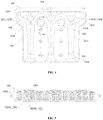
FIG. 1 is a front view of a burner according to an embodiment of the present application; -
FIG. 2 is a top view of a burner according to an embodiment of the present application; -
FIG. 3 is a right view of a burner according to an embodiment of the present application; -
FIG. 4 is a front view of a flame distributor according to an embodiment of the present application; -
FIG. 5 is a top view of a flame distributor according to an embodiment of the present application; and -
FIG. 6 is a cross-sectional view taken along line A-A inFIG. 4 . - In the following, only certain exemplary embodiments are briefly described. As those skilled in the art can realize, the described embodiments may be modified in various different ways without departing from the spirit or scope of the present application. Accordingly, the drawings and description are to be regarded as illustrative in nature and not as restrictive.
- In the first aspect of the present application, a burner is provided.
- The burner of the present application is described below with reference to
FIGS. 1-3 . - Referring to
FIG. 1 , in an embodiment, the burner of the present application comprises a plurality of flame distributors 1 that are arranged in parallel with each other. In combination with reference toFIG. 4 , at least threeejection tubes 101 are provided on each flame distributor 1, and the flame distributor 1 of this embodiment is further provided with agas mixing cavity 102. Wherein, a plurality ofejection tubes 101 are independent of each other, and eachejection tube 101 is in communication with theair mixing cavity 102. A plurality ofejection tubes 101 can eject a larger amount of gas, thereby increasing the combustion intensity, reducing nitrogen oxides emissions, and ensuring its safety during use. - Furthermore, a
fastener 2 can be used, passing through multiple flame distributors 1 to connect flame distributors 1 into a whole so as to form afire grate 10. In this way, a plurality of independent flame distributors 1 can be connected into a whole through the connection byfastener 2 to achieve integral installation, and the connection byfastener 2 is easy to operate and such fixation is secure. - Preferably, both ends of
fastener 2 may protrude relative tofire grate 10, i.e.,fastener 2 has a protruding end. Also, a compressing piece 3 may be arranged at the protruding end offastener 2, and it may compressfire grate 10, thereby reducing the shaking of the flame distributors relative to each other and enhancing the stability of the connection among the plurality of flame distributors. Wherein,fastener 2 may be a bolt fastener, compressing piece 3 may be a nut, and the bolt may be locked by the nut after passing through the fire grate, but the selection and connection form offastener 2 and compressing piece 3 are not limited thereto. - Referring to
FIG. 3 , in an embodiment, thefastener 2 may be in one pair, or in multiple pairs as desired. Wherein, each pair offasteners 2 may be symmetrically arranged relative to thesymmetry axis 106 of the flame distributors 1 in the plumb direction (in combination with reference toFIG. 4 ), whereby the stability of the connection is further ensured. - Referring to
FIGS. 1 and3 , in an embodiment, a first side plate 4 is provided on either side of thefire grate 10. Wherein, both ends of thefastener 2 respectively pass through the corresponding first side plates 4, so that the first side plates 4 and thefire grate 10 may be connected into a whole. Also, both ends (protruding ends) of thefastener 2 may also protrude relative to the first side plates 4, so that the first side plate 4 and thefire grate 10 may be compressed by the compressing piece 3. Thus, after the first side plate 4 and thefire grate 10 are connected and fixed, thefire grate 10 can be simply connected to other components through the first side plate 4. - Referring to
FIGS. 1 and3 , in an embodiment, the lower ends of the first side plates 4 respectively bend towards the outsides of thefire grate 10 and extend horizontally, thereby formingfirst side platforms 401. In this way, thefirst side platform 401 may be used as a connection for connecting the fire grate 10 to other components, the specific manner of which will be described below. - Referring to
FIGS. 1 and3 , in an embodiment, the burner further comprises agas distribution device 5 for supplying gas to the flame distributors 1. Referring toFIG. 3 , thegas distribution device 5 is arranged below theejection tubes 101, the gas may enter into theejection tubes 101 through thegas distribution device 5 and be injected and ejected to the top of the flame distributors 1 through theejection tubes 101. - Furthermore, a plurality of
gas passages 501 is provided in thegas distribution device 5, and the number and the distribution mode of thegas passages 501 should correspond to that of theejection tubes 101. Also, thegas passage 501 may be in communication with theejection tube 101 corresponding to its position. - Specifically, in an embodiment, the
ejection tubes 101 comprises afirst ejection tube 101A, asecond ejection tube 101B, and a third ejection tube 101C. Thegas distribution device 501 may comprise afirst gas passage 501A, asecond gas passage 501B, and a third gas passage 501C. Thefirst gas passage 501A is in communication with thefirst ejection tube 101A corresponding to its position through afirst nozzle 502A; thesecond gas passage 501B is in communication with thesecond ejection tube 101B corresponding to its position through asecond nozzle 502B; the third gas passage 501C is in communication with the third ejection tube 101C corresponding to its position through athird nozzle 502C. - Furthermore, a
second side plate 6 is provided at two sides of thegas distribution device 5, and thesecond side plate 6 is fixedly connected to thegas distribution device 5, wherein the secure connection manner is not specifically defined here. The upper ends of thesecond side plates 6 respectively bend towards the outsides of thegas distribution device 5 and extend horizontally, thereby formingsecond side platforms 601. - Preferably, the
gas distribution device 5 and thefire grate 10 may be fixedly connected at thefirst side platforms 401 and thesecond side platforms 601. Specifically, in an embodiment, abolt 11 or a screw may be used to pass through thefirst side platform 401 and thesecond side platform 601, and be locked by a nut at its protruding end, so that thegas distribution device 5 is fixedly connected to thefire grate 10. Wherein, the part used for secure connection is not limited to bolt or screw, and other parts capable of playing a fastening role may be used here; the part for locking is not limited to nut, and other parts capable of playing a locking role may be used here. - Referring to
FIGS. 1-3 , in an embodiment, a front side plate 7 is provided on the front side of thefire grate 10, and anigniter 8 is provided on the upper portion of the front side plate 7. Anignition portion 80 of theigniter 8 is arranged towards the gas outlet end 103 of the flame distributors 1. In this way, the gas ejected from the gas outlet end 103 of the flame distributors 1 may be ignited by theignition portion 80, thereby achieving combustion. - Furthermore, referring to
FIG. 3 , in an embodiment, theignition portion 80 comprises a first ignition end 801 and a second ignition end 802. - In combination with reference to
FIG. 1 , based on the orientations shown inFIG. 1 , wherein the first ignition end 801 protrudes towards the top of the front side plate 7, and then bends and continues to extend towards the rear of the front side plate 7. In this way, the first ignition end 801 is located above thegas outlet end 103, and the gas ejected from thegas outlet end 103 may be ignited in a larger range, improving the gas utilization rate. - The second ignition end 802 protrudes towards the top of the front side plate 7, and then bends and extends towards the rear of the front side plate 7, with its extending tip bent towards the
gas outlet end 103, that is, bent downward. In this way, the second ignition end 802 is arranged towards thegas outlet end 103, and the gas may be ignited in time when the gas is ejected from thegas outlet end 103, thereby increasing the combustion intensity. - Referring to
FIGS. 1-3 , in an embodiment, the burner further comprises a cooling water pipe 9, and the cooling water pipe 9 may be U-shaped. - During the long-time combustion of the burner, the fire grate would turn red, its temperature would increase, and nitrogen oxides would also be generated. In combination with reference to
FIG. 4 , the flame distributor 1 is provided with at least two first through-holes 104, and two ends of the cooling water pipe 9 respectively pass through the corresponding first through-holes 104 and pass throughout thefire grate 10. In this way, the cooling water pipe 9 may be in close contact with the flame distributors 1, thereby lowering the temperature of the flame distributors 1 (fire grate 10), and further reducing the generated nitrogen oxides. - Furthermore, the first through-
holes 104 are arranged betweenadjacent ejection tubes 101. In this way, each ejection tube 101 (thefirst ejection tube 101A, thesecond ejection tube 101B, and the third ejection tube 101C) may be adjacent to the cooling water pipe 9, and thus cooled by the cooling liquid in the cooling water pipe 9. Thereby, the temperature of the gas in eachejection tube 101 may be lowered, enabling the temperature of the gas lower when it is ejected from thegas outlet end 103, and thus further reducing the generated nitrogen oxides and also lowering the nitrogen oxides emissions. - Referring to
FIG. 4 , in an embodiment, atop plate 105 is snap-fitted with a top of the flame distributor 1. Furthermore, in combination with reference toFIG. 5 , thetop plate 105 has a plurality of fire holes 1051, and the fire holes 1051 may be in communication with thegas outlet end 103, so that the gas ejected from thegas outlet end 103 may be output outwards through the fire holes 1051. - Referring to
FIG. 5 , the fire holes 1051 may be irregularly arranged on thetop plate 105, and the length of the fire holes 1051 are not exactly the same to each other, including a first fire hole 1051A having a longer length and a second fire hole 1051B having a shorter length. Wherein, the second fire hole 1051B having a shorter length outputs a smaller gas flow, therefore, when the gas is ignited by theigniter 8, the height of the flame generated there is thus lower, and the temperature of the flame is also lower. - Preferably, the first through-
holes 104 are arranged adjacent to thetop plate 105, so that the cooling water pipe 9 may bring better cooling effect to thetop plate 105, and thus the gas temperature at the gas output location is further reduced, thereby further reducing the generated nitrogen oxides. - Referring to
FIGS. 4-6 , in an embodiment, the flame distributor 1 comprises afirst housing 107A and asecond housing 107B that are forward-backward symmetrically arranged, that is, theejection tube 101 is formed by thefirst housing 107A and thesecond housing 107B, and the cavity of theejection tube 101 is enclosed and formed by thefirst housing 107A and thesecond housing 107B. Also, theair mixing cavity 102 is enclosed and formed by thefirst housing 107A and thesecond housing 107B. Wherein, thesecond housing 107B is provided with an edge covering 1071 at its edge, and after thesecond housing 107B is snap-fitted to thefirst housing 107A, the edge covering 1071 is pressed onto the surface of thefirst housing 107A, thefirst housing 107 A and thesecond housing 107 B are securely riveted at the edge covering 1071, with more secure fixation and better sealing effect. - Furthermore, the
top plate 105 is provided with a downward extendingflange 1052 at its edge, and when thetop plate 105 is snap-fitted to the flame distributor 1, theflange 1052 is lapped outside thefirst housing 107A and thesecond housing 107B and surrounds them, so that thetop plate 105 and thefirst housing 107A and thesecond housing 107B may be sealingly secured, and therefore, the heat generated by the cooling water pipe 9 may be kept between thetop plate 105 and the flame distributor 1 without flowing outwards, and then, the cooling effect on the flame distributor 1 may be enhanced. - Referring to
FIGS. 4 and6 , in an embodiment, theejection tube 101 may be divided into anegative pressure section 1011, apressure expansion section 1012, and agas mixing section 1013 from bottom to top. - Wherein, the gas enters into the
ejection tube 101 from thenegative pressure section 1011, and then passes through thepressure expansion section 1012 and thegas mixing section 1013. Thenegative pressure section 1011 is provided with an outwardly curved arc-shapedflow guiding face 1014 at its lower end. When the gas enters into theejection tube 101, the arc-shapedflow guiding face 1014 may reduce the collision between the gas and the inner wall of theejection tube 101, allowing the gas to flow smoothly in theejection tube 101. - The
gas mixing section 1013 is in communication with thepressure expansion section 1012, and thegas mixing sections 1013 ofadjacent ejection tubes 101 are in communication with each other, thereby forming agas mixing cavity 102 to help uniformly mix the gas therein. The end faces of thegas mixing cavity 102 are inclined towards either side to formflow guiding slopes 1015, guiding the gas ejected from themixer 102 to either side, so as to reduce the injection pressure of the gas. - Preferably, the surfaces of the
first housing 107A and thesecond housing 107B at the position of theair mixing cavity 102 are respectively recessed towards the inside of theejection tube 101, and correspondingly form a firstconcave portion 1071A and a secondconcave portion 1071B. Wherein, the firstconcave portion 1071A and the secondconcave portion 1071B may depress the gas flow, uniformly mixing the gas. - Further preferably, the first
concave portion 1071A and the secondconcave portion 1071B are in the shape of triangles, and the vertex angle thereof are on the axis of theejection tube 101, and the angular value of the vertex angle may be between 35° ∼ 70°. Thereby, the firstconcave portion 1071A and the secondconcave portion 1071B may sufficiently break up the gas in thegas mixing cavity 102, reducing the gas flow resistance, and thus the gas may be fully ejected outward, improving the combustion intensity. - Preferably, the surfaces of the
first housing 107A and thesecond housing 107B at the top position of thepressure expansion section 1012 respectively protrude towards the outside of theejection tube 101, and correspondingly form afirst protrusion portion 1072A and asecond protrusion portion 1072B. In combination with reference toFIG. 1 , when arranging the flame distributors 1, two adjacent flame distributors 1 may be positioned by and tightened against thefirst protrusion portion 1072A and thesecond protrusion portion 1072B, so that the plurality of flame distributors 1 would not shake upon secured. - In the second aspect of the present application, a water heater is provided.
- The water heater in the present application comprises the above-mentioned burner. Other components of the water heater of this embodiment can be adopted in various technical solutions known to those of ordinary skill in the art now and in the future, and will not be described in detail here.
- In the description of the present application, reference to the term "one embodiment," "some embodiments," "an example," "a specific example," or "some examples" or the like means that the specific features, structures, materials or characteristics described in combination with the embodiment(s) or example(s) are included in at least one embodiment or example of the present application. Moreover, the particular features, structures, materials or characteristics described may be combined in any suitable manner in any one or more embodiments or examples. In addition, those skilled in the art may combine different embodiments or examples described herein or features in different embodiments or examples without causing any contradiction.
- Moreover, the terms such as "first" and "second" are used only for the purpose of description and cannot be understood as indicating or implying relative importance or implicitly indicating the number of technical features indicated. Therefore, the feature defined by "first" or "second" may explicitly or implicitly include at least one of that feature. In the description of the present application, "a plurality of' means two or more, unless otherwise specifically defined.
- The above are only the preferred implementations of the present application. It should be noted that the above preferred implementations should not be regarded as limiting the present application, and the protection scope of the present application should be subject to the scope defined by the claims. For those of ordinary skill in the art, without departing from the spirit and scope of the present application, several improvements and modifications can be made, and these improvements and modifications should also be regarded as the protection scope of the present application.
Claims (10)
- A burner, characterized in that the burner comprises a plurality of flame distributors each flame distributor provided with at least three ejection tubes and the flame distributors arranged in parallel with each other;
a fastener passing through the plurality of the flame distributors and connecting the plurality of the flame distributors into a fire grate; and
a compressing piece provided at an end of the fastener protruding from the fire grate and the compressing piece compressing the fire grate. - The burner according to claim 1, characterized in that the fastener comprises at least one pair of fasteners, each pair of fasteners are symmetrically arranged relative to a symmetry axis of the flame distributors in a plumb direction.
- The burner according to claim 2, characterized in that a first side plate is provided on two sides of the fire grate, two ends of the fastener respectively pass through their corresponding first side plates, and the first side plates and the fire grate are compressed by the compressing piece.
- The burner according to claim 3, characterized in that lower ends of the first side plates respectively bend towards an outside of the fire grate and the lower ends of the first side plates extend horizontally, forming first side platforms.
- The burner according to claim 4, characterized in that the burner further comprises a gas distribution device arranged below the ejection tubes;
a plurality of gas passages are provided in the gas distribution device and the gas passages are in communication with the ejection tubes corresponding to their positions;
a second side plate is provided on two sides of the gas distribution device, and upper ends of the second side plates respectively bend towards an outside of the gas distribution device and the upped ends of the second side plates extend horizontally, forming second side platforms; and
the gas distribution device is fixedly connected to the fire grate at the first side platforms and at the second side platforms. - The burner according to any one of claims 1 to 5, characterized in that a front side plate is provided on a front side of the fire grate, an igniter is provided on an upper portion of the front side plate, and an ignition portion of the igniter is arranged towards a gas outlet end of the flame distributor.
- The burner according to claim 6, characterized in that the ignition portion comprises a first ignition end and a second ignition end;
the first ignition end protrudes towards a top of the front side plate, and the first ignition end bends and extends towards a rear of the front side plate; and
the second ignition end protrudes towards the top of the front side plate, and bends and extends towards the rear of the front side plate, and an extending tip of the second ignition end bends towards the gas outlet end. - The burner according to any one of claims 1 to 5, characterized in that the burner further comprises a cooling water pipe, and the cooling water pipe is U-shaped;
the flame distributor is provided with at least two first through-holes, and two ends of the cooling water pipe respectively pass through the corresponding first through-holes and the two ends of the cooling water pipe pass throughout the fire grate; and
the first through-holes are arranged between adjacent ejection tubes. - The burner according to claim 8, characterized in that wherein a top plate is snap-fitted with a top of the flame distributor, and the top plate is provided with a plurality of fire holes; and
the first through-holes are arranged adjacent to the top plate. - A water heater, characterized in that the water heater comprises a burner according to any one of claims 1 to 9.
Applications Claiming Priority (2)
| Application Number | Priority Date | Filing Date | Title |
|---|---|---|---|
| CN201810461505.6A CN108534139A (en) | 2018-05-15 | 2018-05-15 | Burner and water heater |
| PCT/CN2018/091096 WO2019218413A1 (en) | 2018-05-15 | 2018-06-13 | Burner and water heater |
Publications (3)
| Publication Number | Publication Date |
|---|---|
| EP3795899A1 true EP3795899A1 (en) | 2021-03-24 |
| EP3795899A4 EP3795899A4 (en) | 2021-05-05 |
| EP3795899B1 EP3795899B1 (en) | 2022-05-18 |
Family
ID=63477110
Family Applications (1)
| Application Number | Title | Priority Date | Filing Date |
|---|---|---|---|
| EP18919331.1A Active EP3795899B1 (en) | 2018-05-15 | 2018-06-13 | Burner and water heater |
Country Status (4)
| Country | Link |
|---|---|
| US (1) | US11371698B2 (en) |
| EP (1) | EP3795899B1 (en) |
| CN (1) | CN108534139A (en) |
| WO (1) | WO2019218413A1 (en) |
Cited By (1)
| Publication number | Priority date | Publication date | Assignee | Title |
|---|---|---|---|---|
| IT202100032039A1 (en) * | 2021-12-21 | 2023-06-21 | Beckett Thermal Solutions S R L | Burner module |
Families Citing this family (7)
| Publication number | Priority date | Publication date | Assignee | Title |
|---|---|---|---|---|
| ES2989707T3 (en) * | 2019-04-25 | 2024-11-27 | Wuhu Midea Kitchen & Bath Appliances Mfg Co Ltd | Burner and water heating device |
| CN111981475A (en) * | 2019-05-23 | 2020-11-24 | 广东万家乐燃气具有限公司 | Distributor, combustor and gas hot water equipment of riveted structure |
| CN110274229B (en) * | 2019-06-11 | 2024-11-05 | 广东万家乐燃气具有限公司 | Burner monolithic chip, burner and gas water heater |
| CN111156507A (en) * | 2019-12-23 | 2020-05-15 | 杨斌 | Gas and air mix formula fire entirely and arrange combustor in advance |
| CN113137748B (en) * | 2020-01-19 | 2024-11-01 | 芜湖美的厨卫电器制造有限公司 | Combustor and gas water heater with same |
| CN113137747B (en) * | 2020-01-19 | 2024-11-12 | 芜湖美的厨卫电器制造有限公司 | Burner and gas water heater having the same |
| CN111503896A (en) * | 2020-04-21 | 2020-08-07 | 杨斌 | A fully premixed gas combustion heat exchange integrated device |
Family Cites Families (14)
| Publication number | Priority date | Publication date | Assignee | Title |
|---|---|---|---|---|
| US1935705A (en) * | 1929-09-30 | 1933-11-21 | John S Fuller | Low pressure gas burner |
| US5379750A (en) | 1993-09-16 | 1995-01-10 | Carrier Corporation | Burner mounting assembly for gas furnace |
| FR2740202B1 (en) * | 1995-10-19 | 1997-12-12 | Leblanc Sa E L M | IMPROVEMENTS TO A WATER HEATER, BATH HEATER, GAS BOILER |
| CN104566372A (en) | 2015-01-13 | 2015-04-29 | 天津城建大学 | Water-cooled fully premixed burner |
| CN205037302U (en) * | 2015-06-04 | 2016-02-17 | 芜湖美的厨卫电器制造有限公司 | Distributor and gas heater |
| WO2016193904A1 (en) | 2015-06-04 | 2016-12-08 | Polidoro S.P.A. | Plate gas burner for boiler |
| CN204901764U (en) * | 2015-07-28 | 2015-12-23 | 芜湖美的厨卫电器制造有限公司 | Distributor of combustor and water heater that has it |
| CN205026669U (en) * | 2015-08-06 | 2016-02-10 | 广州迪森家用锅炉制造有限公司 | A combustor for gas heating water heater or gas heater |
| CN107816737A (en) * | 2016-09-11 | 2018-03-20 | 王颖智 | A kind of igniter for being used to separate the infrared burner of tray for combustion |
| CN107270289A (en) * | 2017-07-10 | 2017-10-20 | 广东万和新电气股份有限公司 | A kind of burner and gas heater |
| CN207065570U (en) * | 2017-08-16 | 2018-03-02 | 芜湖美的厨卫电器制造有限公司 | Burner and gas heater |
| CN107477578A (en) * | 2017-10-09 | 2017-12-15 | 珠海格力电器股份有限公司 | Combustor and water heater |
| CN107620963A (en) * | 2017-11-01 | 2018-01-23 | 芜湖美的厨卫电器制造有限公司 | Burner and water heater having same |
| CN208269127U (en) * | 2018-05-15 | 2018-12-21 | 芜湖美的厨卫电器制造有限公司 | Burner and water heater |
-
2018
- 2018-05-15 CN CN201810461505.6A patent/CN108534139A/en active Pending
- 2018-06-13 EP EP18919331.1A patent/EP3795899B1/en active Active
- 2018-06-13 US US17/055,126 patent/US11371698B2/en active Active
- 2018-06-13 WO PCT/CN2018/091096 patent/WO2019218413A1/en not_active Ceased
Cited By (3)
| Publication number | Priority date | Publication date | Assignee | Title |
|---|---|---|---|---|
| IT202100032039A1 (en) * | 2021-12-21 | 2023-06-21 | Beckett Thermal Solutions S R L | Burner module |
| EP4202298A1 (en) * | 2021-12-21 | 2023-06-28 | Beckett Thermal Solutions S.R.L. | Burner module |
| EP4202298B1 (en) | 2021-12-21 | 2024-03-20 | Beckett Thermal Solutions S.R.L. | Burner module |
Also Published As
| Publication number | Publication date |
|---|---|
| US11371698B2 (en) | 2022-06-28 |
| CN108534139A (en) | 2018-09-14 |
| US20210215336A1 (en) | 2021-07-15 |
| EP3795899B1 (en) | 2022-05-18 |
| WO2019218413A1 (en) | 2019-11-21 |
| EP3795899A4 (en) | 2021-05-05 |
Similar Documents
| Publication | Publication Date | Title |
|---|---|---|
| EP3795899A1 (en) | Burner and water heater | |
| US8157189B2 (en) | Premixing direct injector | |
| CN110762526B (en) | Combustor and water heater using same | |
| CN104676591B (en) | Burner and gas stove with same | |
| CN109404905A (en) | Burners and Gas Water Heaters | |
| CN207065570U (en) | Burner and gas heater | |
| KR20100006606A (en) | A coal burner of unnecessary preheating coal dust by combustion method | |
| CN215411868U (en) | Cyclone flue gas recirculation gas burner | |
| JP2000346316A (en) | Combustion equipment | |
| KR102398157B1 (en) | Gas burner | |
| CN208205002U (en) | Burner and the water heater for applying it | |
| CN108443880B (en) | Flame distributor and burners and water heaters using it | |
| CN215062041U (en) | Multistage burning nozzle case | |
| JP3454441B2 (en) | Method and apparatus for low nitrogen oxide combustion combustion | |
| CN212408659U (en) | Infrared burner | |
| CN110375298B (en) | Combustor assembly and gas water heater | |
| CN208269127U (en) | Burner and water heater | |
| CN222798986U (en) | Burners and cooking appliances | |
| CN222992891U (en) | A premix burner | |
| CN220728237U (en) | Combustion head and low-nitrogen combustor | |
| CN221375666U (en) | Burner and domestic electrical appliance | |
| WO2019219037A1 (en) | Distributor and combustor and water heater having same | |
| CN210979834U (en) | A kind of burner | |
| JP3891531B2 (en) | Gas combustion heating device | |
| CN114353071A (en) | Combustor and gas water heater |
Legal Events
| Date | Code | Title | Description |
|---|---|---|---|
| STAA | Information on the status of an ep patent application or granted ep patent |
Free format text: STATUS: THE INTERNATIONAL PUBLICATION HAS BEEN MADE |
|
| PUAI | Public reference made under article 153(3) epc to a published international application that has entered the european phase |
Free format text: ORIGINAL CODE: 0009012 |
|
| STAA | Information on the status of an ep patent application or granted ep patent |
Free format text: STATUS: REQUEST FOR EXAMINATION WAS MADE |
|
| 17P | Request for examination filed |
Effective date: 20201214 |
|
| AK | Designated contracting states |
Kind code of ref document: A1 Designated state(s): AL AT BE BG CH CY CZ DE DK EE ES FI FR GB GR HR HU IE IS IT LI LT LU LV MC MK MT NL NO PL PT RO RS SE SI SK SM TR |
|
| AX | Request for extension of the european patent |
Extension state: BA ME |
|
| A4 | Supplementary search report drawn up and despatched |
Effective date: 20210401 |
|
| RIC1 | Information provided on ipc code assigned before grant |
Ipc: F23D 14/04 20060101AFI20210326BHEP Ipc: F24H 9/18 20060101ALI20210326BHEP Ipc: F23D 14/78 20060101ALI20210326BHEP |
|
| DAV | Request for validation of the european patent (deleted) | ||
| DAX | Request for extension of the european patent (deleted) | ||
| REG | Reference to a national code |
Ref country code: DE Ref legal event code: R079 Ref document number: 602018035886 Country of ref document: DE Free format text: PREVIOUS MAIN CLASS: F23D0014040000 Ipc: F23D0014640000 |
|
| GRAP | Despatch of communication of intention to grant a patent |
Free format text: ORIGINAL CODE: EPIDOSNIGR1 |
|
| STAA | Information on the status of an ep patent application or granted ep patent |
Free format text: STATUS: GRANT OF PATENT IS INTENDED |
|
| RIC1 | Information provided on ipc code assigned before grant |
Ipc: F23D 14/78 20060101ALI20211104BHEP Ipc: F23D 14/04 20060101ALI20211104BHEP Ipc: F23D 14/84 20060101ALI20211104BHEP Ipc: F23D 14/70 20060101ALI20211104BHEP Ipc: F23D 14/64 20060101AFI20211104BHEP |
|
| INTG | Intention to grant announced |
Effective date: 20211125 |
|
| GRAJ | Information related to disapproval of communication of intention to grant by the applicant or resumption of examination proceedings by the epo deleted |
Free format text: ORIGINAL CODE: EPIDOSDIGR1 |
|
| STAA | Information on the status of an ep patent application or granted ep patent |
Free format text: STATUS: REQUEST FOR EXAMINATION WAS MADE |
|
| GRAP | Despatch of communication of intention to grant a patent |
Free format text: ORIGINAL CODE: EPIDOSNIGR1 |
|
| STAA | Information on the status of an ep patent application or granted ep patent |
Free format text: STATUS: GRANT OF PATENT IS INTENDED |
|
| GRAS | Grant fee paid |
Free format text: ORIGINAL CODE: EPIDOSNIGR3 |
|
| GRAA | (expected) grant |
Free format text: ORIGINAL CODE: 0009210 |
|
| STAA | Information on the status of an ep patent application or granted ep patent |
Free format text: STATUS: THE PATENT HAS BEEN GRANTED |
|
| INTC | Intention to grant announced (deleted) | ||
| INTG | Intention to grant announced |
Effective date: 20220412 |
|
| RAP3 | Party data changed (applicant data changed or rights of an application transferred) |
Owner name: MIDEA GROUP CO., LTD. Owner name: WUHU MIDEA KITCHEN AND BATH APPLIANCES MFG. CO, LTD. |
|
| AK | Designated contracting states |
Kind code of ref document: B1 Designated state(s): AL AT BE BG CH CY CZ DE DK EE ES FI FR GB GR HR HU IE IS IT LI LT LU LV MC MK MT NL NO PL PT RO RS SE SI SK SM TR |
|
| REG | Reference to a national code |
Ref country code: GB Ref legal event code: FG4D |
|
| REG | Reference to a national code |
Ref country code: CH Ref legal event code: EP |
|
| REG | Reference to a national code |
Ref country code: IE Ref legal event code: FG4D |
|
| REG | Reference to a national code |
Ref country code: DE Ref legal event code: R096 Ref document number: 602018035886 Country of ref document: DE |
|
| REG | Reference to a national code |
Ref country code: AT Ref legal event code: REF Ref document number: 1493348 Country of ref document: AT Kind code of ref document: T Effective date: 20220615 |
|
| REG | Reference to a national code |
Ref country code: LT Ref legal event code: MG9D |
|
| REG | Reference to a national code |
Ref country code: NL Ref legal event code: MP Effective date: 20220518 |
|
| REG | Reference to a national code |
Ref country code: AT Ref legal event code: MK05 Ref document number: 1493348 Country of ref document: AT Kind code of ref document: T Effective date: 20220518 |
|
| PG25 | Lapsed in a contracting state [announced via postgrant information from national office to epo] |
Ref country code: SE Free format text: LAPSE BECAUSE OF FAILURE TO SUBMIT A TRANSLATION OF THE DESCRIPTION OR TO PAY THE FEE WITHIN THE PRESCRIBED TIME-LIMIT Effective date: 20220518 Ref country code: PT Free format text: LAPSE BECAUSE OF FAILURE TO SUBMIT A TRANSLATION OF THE DESCRIPTION OR TO PAY THE FEE WITHIN THE PRESCRIBED TIME-LIMIT Effective date: 20220919 Ref country code: NO Free format text: LAPSE BECAUSE OF FAILURE TO SUBMIT A TRANSLATION OF THE DESCRIPTION OR TO PAY THE FEE WITHIN THE PRESCRIBED TIME-LIMIT Effective date: 20220818 Ref country code: NL Free format text: LAPSE BECAUSE OF FAILURE TO SUBMIT A TRANSLATION OF THE DESCRIPTION OR TO PAY THE FEE WITHIN THE PRESCRIBED TIME-LIMIT Effective date: 20220518 Ref country code: LT Free format text: LAPSE BECAUSE OF FAILURE TO SUBMIT A TRANSLATION OF THE DESCRIPTION OR TO PAY THE FEE WITHIN THE PRESCRIBED TIME-LIMIT Effective date: 20220518 Ref country code: HR Free format text: LAPSE BECAUSE OF FAILURE TO SUBMIT A TRANSLATION OF THE DESCRIPTION OR TO PAY THE FEE WITHIN THE PRESCRIBED TIME-LIMIT Effective date: 20220518 Ref country code: GR Free format text: LAPSE BECAUSE OF FAILURE TO SUBMIT A TRANSLATION OF THE DESCRIPTION OR TO PAY THE FEE WITHIN THE PRESCRIBED TIME-LIMIT Effective date: 20220819 Ref country code: FI Free format text: LAPSE BECAUSE OF FAILURE TO SUBMIT A TRANSLATION OF THE DESCRIPTION OR TO PAY THE FEE WITHIN THE PRESCRIBED TIME-LIMIT Effective date: 20220518 Ref country code: BG Free format text: LAPSE BECAUSE OF FAILURE TO SUBMIT A TRANSLATION OF THE DESCRIPTION OR TO PAY THE FEE WITHIN THE PRESCRIBED TIME-LIMIT Effective date: 20220818 Ref country code: AT Free format text: LAPSE BECAUSE OF FAILURE TO SUBMIT A TRANSLATION OF THE DESCRIPTION OR TO PAY THE FEE WITHIN THE PRESCRIBED TIME-LIMIT Effective date: 20220518 |
|
| PG25 | Lapsed in a contracting state [announced via postgrant information from national office to epo] |
Ref country code: RS Free format text: LAPSE BECAUSE OF FAILURE TO SUBMIT A TRANSLATION OF THE DESCRIPTION OR TO PAY THE FEE WITHIN THE PRESCRIBED TIME-LIMIT Effective date: 20220518 Ref country code: PL Free format text: LAPSE BECAUSE OF FAILURE TO SUBMIT A TRANSLATION OF THE DESCRIPTION OR TO PAY THE FEE WITHIN THE PRESCRIBED TIME-LIMIT Effective date: 20220518 Ref country code: LV Free format text: LAPSE BECAUSE OF FAILURE TO SUBMIT A TRANSLATION OF THE DESCRIPTION OR TO PAY THE FEE WITHIN THE PRESCRIBED TIME-LIMIT Effective date: 20220518 Ref country code: IS Free format text: LAPSE BECAUSE OF FAILURE TO SUBMIT A TRANSLATION OF THE DESCRIPTION OR TO PAY THE FEE WITHIN THE PRESCRIBED TIME-LIMIT Effective date: 20220918 |
|
| PG25 | Lapsed in a contracting state [announced via postgrant information from national office to epo] |
Ref country code: SM Free format text: LAPSE BECAUSE OF FAILURE TO SUBMIT A TRANSLATION OF THE DESCRIPTION OR TO PAY THE FEE WITHIN THE PRESCRIBED TIME-LIMIT Effective date: 20220518 Ref country code: SK Free format text: LAPSE BECAUSE OF FAILURE TO SUBMIT A TRANSLATION OF THE DESCRIPTION OR TO PAY THE FEE WITHIN THE PRESCRIBED TIME-LIMIT Effective date: 20220518 Ref country code: RO Free format text: LAPSE BECAUSE OF FAILURE TO SUBMIT A TRANSLATION OF THE DESCRIPTION OR TO PAY THE FEE WITHIN THE PRESCRIBED TIME-LIMIT Effective date: 20220518 Ref country code: ES Free format text: LAPSE BECAUSE OF FAILURE TO SUBMIT A TRANSLATION OF THE DESCRIPTION OR TO PAY THE FEE WITHIN THE PRESCRIBED TIME-LIMIT Effective date: 20220518 Ref country code: EE Free format text: LAPSE BECAUSE OF FAILURE TO SUBMIT A TRANSLATION OF THE DESCRIPTION OR TO PAY THE FEE WITHIN THE PRESCRIBED TIME-LIMIT Effective date: 20220518 Ref country code: DK Free format text: LAPSE BECAUSE OF FAILURE TO SUBMIT A TRANSLATION OF THE DESCRIPTION OR TO PAY THE FEE WITHIN THE PRESCRIBED TIME-LIMIT Effective date: 20220518 Ref country code: CZ Free format text: LAPSE BECAUSE OF FAILURE TO SUBMIT A TRANSLATION OF THE DESCRIPTION OR TO PAY THE FEE WITHIN THE PRESCRIBED TIME-LIMIT Effective date: 20220518 |
|
| REG | Reference to a national code |
Ref country code: CH Ref legal event code: PL |
|
| REG | Reference to a national code |
Ref country code: BE Ref legal event code: MM Effective date: 20220630 |
|
| REG | Reference to a national code |
Ref country code: DE Ref legal event code: R097 Ref document number: 602018035886 Country of ref document: DE |
|
| PG25 | Lapsed in a contracting state [announced via postgrant information from national office to epo] |
Ref country code: MC Free format text: LAPSE BECAUSE OF FAILURE TO SUBMIT A TRANSLATION OF THE DESCRIPTION OR TO PAY THE FEE WITHIN THE PRESCRIBED TIME-LIMIT Effective date: 20220518 |
|
| PLBE | No opposition filed within time limit |
Free format text: ORIGINAL CODE: 0009261 |
|
| STAA | Information on the status of an ep patent application or granted ep patent |
Free format text: STATUS: NO OPPOSITION FILED WITHIN TIME LIMIT |
|
| PG25 | Lapsed in a contracting state [announced via postgrant information from national office to epo] |
Ref country code: AL Free format text: LAPSE BECAUSE OF FAILURE TO SUBMIT A TRANSLATION OF THE DESCRIPTION OR TO PAY THE FEE WITHIN THE PRESCRIBED TIME-LIMIT Effective date: 20220518 |
|
| 26N | No opposition filed |
Effective date: 20230221 |
|
| PG25 | Lapsed in a contracting state [announced via postgrant information from national office to epo] |
Ref country code: LU Free format text: LAPSE BECAUSE OF NON-PAYMENT OF DUE FEES Effective date: 20220613 Ref country code: LI Free format text: LAPSE BECAUSE OF NON-PAYMENT OF DUE FEES Effective date: 20220630 Ref country code: IE Free format text: LAPSE BECAUSE OF NON-PAYMENT OF DUE FEES Effective date: 20220613 Ref country code: CH Free format text: LAPSE BECAUSE OF NON-PAYMENT OF DUE FEES Effective date: 20220630 |
|
| PG25 | Lapsed in a contracting state [announced via postgrant information from national office to epo] |
Ref country code: SI Free format text: LAPSE BECAUSE OF FAILURE TO SUBMIT A TRANSLATION OF THE DESCRIPTION OR TO PAY THE FEE WITHIN THE PRESCRIBED TIME-LIMIT Effective date: 20220518 Ref country code: BE Free format text: LAPSE BECAUSE OF NON-PAYMENT OF DUE FEES Effective date: 20220630 |
|
| P01 | Opt-out of the competence of the unified patent court (upc) registered |
Effective date: 20230526 |
|
| PG25 | Lapsed in a contracting state [announced via postgrant information from national office to epo] |
Ref country code: IT Free format text: LAPSE BECAUSE OF FAILURE TO SUBMIT A TRANSLATION OF THE DESCRIPTION OR TO PAY THE FEE WITHIN THE PRESCRIBED TIME-LIMIT Effective date: 20220518 |
|
| PG25 | Lapsed in a contracting state [announced via postgrant information from national office to epo] |
Ref country code: MK Free format text: LAPSE BECAUSE OF FAILURE TO SUBMIT A TRANSLATION OF THE DESCRIPTION OR TO PAY THE FEE WITHIN THE PRESCRIBED TIME-LIMIT Effective date: 20220511 Ref country code: CY Free format text: LAPSE BECAUSE OF FAILURE TO SUBMIT A TRANSLATION OF THE DESCRIPTION OR TO PAY THE FEE WITHIN THE PRESCRIBED TIME-LIMIT Effective date: 20220511 |
|
| PG25 | Lapsed in a contracting state [announced via postgrant information from national office to epo] |
Ref country code: HU Free format text: LAPSE BECAUSE OF FAILURE TO SUBMIT A TRANSLATION OF THE DESCRIPTION OR TO PAY THE FEE WITHIN THE PRESCRIBED TIME-LIMIT; INVALID AB INITIO Effective date: 20180613 |
|
| PG25 | Lapsed in a contracting state [announced via postgrant information from national office to epo] |
Ref country code: TR Free format text: LAPSE BECAUSE OF FAILURE TO SUBMIT A TRANSLATION OF THE DESCRIPTION OR TO PAY THE FEE WITHIN THE PRESCRIBED TIME-LIMIT Effective date: 20220511 |
|
| PG25 | Lapsed in a contracting state [announced via postgrant information from national office to epo] |
Ref country code: MT Free format text: LAPSE BECAUSE OF FAILURE TO SUBMIT A TRANSLATION OF THE DESCRIPTION OR TO PAY THE FEE WITHIN THE PRESCRIBED TIME-LIMIT Effective date: 20220511 |
|
| PG25 | Lapsed in a contracting state [announced via postgrant information from national office to epo] |
Ref country code: BG Free format text: LAPSE BECAUSE OF FAILURE TO SUBMIT A TRANSLATION OF THE DESCRIPTION OR TO PAY THE FEE WITHIN THE PRESCRIBED TIME-LIMIT Effective date: 20220518 |
|
| PG25 | Lapsed in a contracting state [announced via postgrant information from national office to epo] |
Ref country code: BG Free format text: LAPSE BECAUSE OF FAILURE TO SUBMIT A TRANSLATION OF THE DESCRIPTION OR TO PAY THE FEE WITHIN THE PRESCRIBED TIME-LIMIT Effective date: 20220518 |
|
| PGFP | Annual fee paid to national office [announced via postgrant information from national office to epo] |
Ref country code: DE Payment date: 20250625 Year of fee payment: 8 |
|
| PGFP | Annual fee paid to national office [announced via postgrant information from national office to epo] |
Ref country code: GB Payment date: 20250620 Year of fee payment: 8 |
|
| PGFP | Annual fee paid to national office [announced via postgrant information from national office to epo] |
Ref country code: FR Payment date: 20250620 Year of fee payment: 8 |