EP4202132A1 - Sanitäranordnung - Google Patents
Sanitäranordnung Download PDFInfo
- Publication number
- EP4202132A1 EP4202132A1 EP21216752.2A EP21216752A EP4202132A1 EP 4202132 A1 EP4202132 A1 EP 4202132A1 EP 21216752 A EP21216752 A EP 21216752A EP 4202132 A1 EP4202132 A1 EP 4202132A1
- Authority
- EP
- European Patent Office
- Prior art keywords
- contact
- spacer
- pipe
- stop surface
- flange
- Prior art date
- Legal status (The legal status is an assumption and is not a legal conclusion. Google has not performed a legal analysis and makes no representation as to the accuracy of the status listed.)
- Granted
Links
Images


Classifications
-
- E—FIXED CONSTRUCTIONS
- E03—WATER SUPPLY; SEWERAGE
- E03C—DOMESTIC PLUMBING INSTALLATIONS FOR FRESH WATER OR WASTE WATER; SINKS
- E03C1/00—Domestic plumbing installations for fresh water or waste water; Sinks
- E03C1/02—Plumbing installations for fresh water
- E03C1/021—Devices for positioning or connecting of water supply lines
-
- E—FIXED CONSTRUCTIONS
- E03—WATER SUPPLY; SEWERAGE
- E03C—DOMESTIC PLUMBING INSTALLATIONS FOR FRESH WATER OR WASTE WATER; SINKS
- E03C1/00—Domestic plumbing installations for fresh water or waste water; Sinks
- E03C1/02—Plumbing installations for fresh water
- E03C1/025—Water supply lines as such, e.g. shower hoses
-
- E—FIXED CONSTRUCTIONS
- E03—WATER SUPPLY; SEWERAGE
- E03C—DOMESTIC PLUMBING INSTALLATIONS FOR FRESH WATER OR WASTE WATER; SINKS
- E03C1/00—Domestic plumbing installations for fresh water or waste water; Sinks
- E03C1/02—Plumbing installations for fresh water
- E03C2001/028—Alignment aids for plumbing installations
Definitions
- the present invention relates to a sanitary arrangement according to claim 1, a wall arrangement according to claim 15 and a method according to claim 16.
- a water-carrying connection element is attached to the back of a wall and guided through the wall.
- the pipe section protrudes a little further or less far from the front or only protrudes into the opening in the wall but no longer.
- the object of the invention is to specify a sanitary arrangement which has improved properties with regard to the placement of a pipe connection piece with respect to an opening in a wall structure.
- a sanitary arrangement comprises a pipe connection piece with a pipe housing, which delimits at least one pipe duct, and a flange section protruding from the pipe housing with a Flange surface, wherein the pipe connecting piece extends from the flange surface with a pipe section extending along a straight central axis to a pipe end, and a spacer with a contact surface for direct or indirect mounting of the spacer on a wall structure, and with a first stop surface and with a second stop surface.
- the distance between the first stop surface and the contact surface seen in the direction of the surface normal of the contact surface is different from the distance between the second stop surface and the contact surface.
- the spacer can be brought into contact either with the first stop surface or with the second stop surface with the flange surface in such a way that the distance between the contact surface of the spacer and the pipe end when contacting the first stop surface is different from the distance between the contact surface of the Spacer and the pipe end is in contact with the second stop surface.
- the distance is in each case the distance viewed in the direction of the central axis of the pipe section or in the direction of the surface normals mentioned.
- the spacer can be placed on the flange surface in two different positions, so that the pipe end protruding freely from the contact surface has a different length.
- the advantage of the spacer with its two stop surfaces is that two different lengths of the pipe end protruding freely from the contact surface can be achieved with one spacer.
- the sanitary arrangement can be very easily adapted to different wall thicknesses.
- the adjustment can be made in such a way that the freely protruding length of the tube end essentially corresponds to the thickness of the wall, so that the tube end can be mounted flush with one of the two wall surfaces.
- the distances between the stop surfaces can be selected so that the spacer can be used for common wall thicknesses.
- the pipe end is preferably designed on the outside as a cylinder with a constant diameter. On the inside, the pipe end preferably has an internal thread for connecting a pipe.
- the spacer includes in addition to the first and the second stop surface further stop surfaces, which allow the provision of other different distances.
- the spacer includes a central opening through which the pipe section is passed.
- the opening preferably has a diameter which is larger than the outer diameter of the pipe section.
- the tube section and the central opening preferably have a circular diameter.
- the central axis of the central opening is collinear with the central axis of the pipe section.
- the stop surfaces preferably run parallel to the contact surface.
- the second abutment surface is preferably provided by at least one elevation which protrudes from the first abutment surface. If there are several stop surfaces, preferably several elevations extending away from the first stop surface are arranged.
- the at least one elevation particularly preferably has a large number of incisions, the incisions preferably extending as far as the first stop surface.
- each of the elevations is arranged opposite one another as seen with respect to the central axis, each of the elevations having at least one surface section which provides part of the second stop surface.
- the flange section preferably has at least one recess, with the recess and said at least one elevation being formed in such a way that in a first relative position between spacer and flange section, the elevation protrudes into the at least one recess, and the first stop surface can be brought into contact with the flange surface and that in a second relative position between the spacer and the flange section, the elevation with the second stop surface can be brought into contact with the flange surface.
- a particularly preferred embodiment is characterized in that the Flange portion has at least one first recess and at least one second recess, wherein the shape of the first recess is different from the shape of the second recess.
- the elevation in a first relative position between the spacer and the flange section, the elevation is formed with the second abutment surface and the second recess is formed in such a way that the elevation protrudes into the second recess and the first abutment surface can then be brought into contact with the contact surface, and in In a second relative position between the spacer and the flange section, the elevation with the second stop surface and the first recess are designed in such a way that the second stop surface does not lie in the area of the first recess, but can be brought into contact with the flange surface.
- the particularly preferred embodiment is further characterized in that the flange section has two opposite first recesses with respect to the center axis of the tube section and two second recesses opposite with respect to the center axis of the tube section, the shape of the first recesses being different from the shape of the second recesses.
- the recesses are preferably arranged in respective angular segments. There are preferably four angle segments of 90° each and a recess is arranged in each of the angle segments.
- the recesses are preferably distributed at regular intervals around the central axis of the pipe section.
- the spacer preferably also has two recesses arranged opposite one another.
- the flange section and the spacer preferably have a plurality of through-openings through which a fastening element for fastening the sanitary arrangement to a supporting structure can be guided.
- the hole pattern of the through-openings in the flange section is designed to match the hole pattern of the through-openings in the spacer, so that the two hole patterns match one another in every relative position.
- the pipe connection piece preferably has at least one further pipe section on the side opposite the pipe section, the further pipe section preferably comprising a pressing contour via which the pipe connection piece can be connected to a pipe.
- the further pipe section can be of any desired design. Especially as a pipe bend, a T-piece, a straight pipe section, etc.
- At least one of the abutment surfaces mentioned is preferably provided by a plurality of surface sections. Preferably at least one of said abutment surfaces is provided by a continuous surface.
- the first stop surface is preferably provided as a continuous surface and the second stop surface is provided by a plurality of surface sections.
- the sanitary arrangement preferably also has a damping element which can be placed on the contact surface of the spacer, the damping element having a bearing surface with which the damping element can rest on a wall structure.
- the contact surface of the spacer lies indirectly on the wall structure.
- the damping element is preferably designed as a thin disk and has a thickness of 2 to 4 millimeters.
- the damping element is preferably made of a soft material, such as ethylene-propylene-diene rubber, in particular EPDM 60 IRHD.
- the outline of the contact surface, seen in the direction of the surface normal of the contact surface, and the outline of the damping element, seen in the same direction, have the same shape.
- the damping element extends over the entire contact area.
- the damping element and the contact surface each have a coding element, so that the damping element can be placed on the contact surface in an aligned and determined position.
- the coding element is a recess on the side of the damping element and the coding element on the side of the spacer is preferably a cam which protrudes into the recess when the damping element is on the contact surface rests.
- the recess can also be arranged on the spacer and the cam can be arranged on the damping element.
- each area mentioned can be enlarged or reduced by 1 to 10 millimeters. This is subject to the condition that the distance when it rests on the first stop surface is different from the distance when it rests on the second stop surface.
- a wall arrangement comprises a sanitary arrangement according to the above description and a wall structure with a front side and a rear side, the spacer resting directly or indirectly via the mentioned damping element with the contact surface on the rear side and the pipe section with the pipe end extending through the wall structure, the The end of the pipe should preferably be flush with the front.
- a method for installing a wall arrangement is characterized in that, in a first step, the distance between the front side and the rear side is determined, that in a subsequent step, based on the determined distance, the spacer is connected either to the first stop surface or to the second stop surface Flange surface is connected to the pipe connection piece, and that in a further step the sanitary arrangement is guided with the pipe section through the wall structure until the contact surface rests on the back.
- the sanitary arrangement 1 comprises a pipe connection piece 2 and a spacer 9 which can be connected to the pipe connection piece 2 .
- the spacer 9 can be positioned in two different positions relative to the pipe connection piece 2 . Due to the different positioning, the distance between a contact surface 10 of the spacer 9 and the pipe end 8 of the pipe connection piece 2 can be adjusted.
- the pipe connection piece 2 has a pipe housing 3 which delimits at least one pipe channel 4 . Furthermore, the pipe connection piece 2 has a flange section 5 which extends outwards away from the pipe housing 3 . The flange section 5 has a flange surface 6 . The pipe connection piece 2 extends from the flange surface 6 with a pipe section 7 along a straight central axis M to the pipe end 6.
- the pipe section 7 preferably has an internal thread for connecting a pipe which can be routed to a sanitary article.
- another pipe section 18 is arranged on the side opposite the pipe section 7, another pipe section 18 is arranged.
- the further pipe section 18 here has the shape of a pipe bend, which deflects the pipe channel 4 by 90°. However, the further pipe section 18 can also be designed in a different way. For example, as a straight pipe section, as a T-piece, etc.
- the further pipe section 18 preferably has a pressing contour 19, via which the pipe connection piece 2 can be connected to a pipe.
- the spacer 9 has a contact surface 10 , a first stop surface 11 and a second stop surface 12 . With the contact surface 10, the spacer 9 can rest directly on a wall structure in the installed state or indirectly via the damping element 20 described below.
- the first stop surface 11 and the second stop surface 12 are arranged at different distances from the contact surface 20 .
- the distance A1 between the first stop surface 11 and the contact surface 10 or the bearing surface 26 of the damping element 20 seen in the direction of the surface normal F of the contact surface 10 is different from the distance A2 between the second stop surface 12 and the contact surface 10 or the bearing surface 26 of the Damping element 20.
- the distances A1 and A2 are in the figures 4 and 5 as well as 9 and 10 drawn.
- the spacer 9 can be brought into contact either with the first stop surface 11 or with the second stop surface 12 with the flange surface 6 in such a way that the distance D1 seen in the direction of the central axis M between the contact surface 10 of the spacer 9 or the bearing surface 26 of the Damping element 20 and the pipe end 8 when making contact with the first stop surface 11 differs from the distance D2 seen in the direction of the central axis M between the contact surface 10 of the spacer 9 or the bearing surface 26 of the damping element 20 and the pipe end 8 when making contact with the second Stop surface 12 is.
- the distances D1 and D2 are in the figures 4 and 5 as well as 9 and 10 drawn.
- the distances D1 and D2 essentially correspond to the wall thickness of a wall structure W through which the pipe section 7 is passed. Consequently, depending on the relative position of the spacer 9, the distance D1 and D2 can be adjusted according to the wall thickness.
- the spacer 9 is preferably made of plastic. In the embodiment shown, the spacer 9 has a central opening 13 through which the pipe section 7 can be passed.
- the first stop surface 11 is provided by the rear side of the spacer 9 opposite the contact surface 10 .
- the second stop surface 12 is part of an elevation 14 which extends away from the first stop surface 11 .
- two elevations 14 are arranged, which are diametrically opposite one another with respect to the central axis M or the central opening 13 .
- the elevations 14 also have a large number of incisions 22 which extend into the elevations 14 from the second stop surface 12 .
- the second stop surface 12 is provided by a multiplicity of surface sections.
- Figures 1 to 5 the first relative position between spacer 9 and flange section 5 and the Figures 6 to 10 show the second relative position between spacer 9 and flange section 5.
- first recesses 15 are present in the embodiment shown, namely two first recesses 15 and two second recesses 16.
- Two first recesses 15 are arranged opposite one another and two second ones Recesses 16 are also arranged opposite one another.
- the first recesses 15 have a different shape than the second recesses 16 .
- the elevation 14 is formed with the second abutment surface 12 and the second recess 16 in such a way that the elevation 14 protrudes into the second recess 16 and the first abutment surface 11 then makes contact with the contact surface 10 is bringable.
- the elevation 14 is formed with the second stop surface 12 and the first recess 15 in such a way that the second stop surface 12 does not lie in the area of the first recess 11, but rather with the flange surface 6 in Contact can be brought.
- the recesses 15, 16 are preferably arranged in respective angular segments. There are preferably four angle segments of 90° each and a recess 15, 16 is arranged in each of the angle segments.
- the spacer 9 has two recesses 23 which are arranged opposite one another.
- the flange section 5 and the spacer 9 have a plurality of through openings 17 .
- the hole pattern of the through-openings 17 in the flange section 5 is designed to match the hole pattern of the through-openings 17 in the spacer 9, so that the two hole patterns match one another in every relative position.
- a fastening element for fastening the sanitary arrangement 1 to a supporting structure can be passed through the through-openings 17 .
- the sanitary arrangement also has a damping element 20 which can be placed on the contact surface of the spacer 9 .
- the damping element 20 has a thickness of 2 to 4 millimeters.
- the outline of the contact surface 10 in the direction of the surface normal of the contact surface 10 seen and the outline of the cushioning element 20 seen in the same direction have the same shape. Furthermore, the damping element 20 and the contact surface 10 each have a coding element 21, so that the damping element 20 can be placed on the contact surface 10 in an aligned and determined position.
- the coding element 21 is a recess on the side of the damping element and the coding element 21 is a cam on the side of the spacer.
- a wall structure W is also shown.
- the wall structure W is part of a wall arrangement, which further includes the sanitary arrangement 1 according to the above description.
- the wall structure W has a front 24 and a back 25 .
- the tube section 7 extends through the wall structure W with the tube end 8 .
- the pipe end 8 is preferably flush with the front side 24 to lie.
- the sanitary arrangement 1 is in indirect contact with the rear side 25 via the damping element 20.
- the distance between the front and rear is determined in a first step, so that in a subsequent step, based on the determined distance, the spacer 9 is connected either to the first stop surface 11 or to the second stop surface 12 to the flange surface 6 towards is connected to the pipe connection piece 2, and that in a further step the sanitary arrangement is guided with the pipe section 7 through the wall structure until the contact surface 10 rests on the back.
Landscapes
- Health & Medical Sciences (AREA)
- Life Sciences & Earth Sciences (AREA)
- Engineering & Computer Science (AREA)
- Hydrology & Water Resources (AREA)
- Public Health (AREA)
- Water Supply & Treatment (AREA)
- Sanitary Device For Flush Toilet (AREA)
Abstract
Description
- Die vorliegende Erfindung betrifft eine Sanitäranordnung nach Anspruch 1, eine Wandanordnung nach Anspruch 15 und ein Verfahren nach Anspruch 16.
- Im Bereich der Sanitärtechnik werden vermehrt vorfabrizierte Badezimmer eingesetzt. Solche Badezimmer werden als Kabinen gefertigt und mit Sanitärartikeln, wie Toiletten, Duschen, Waschtische, etc, werkseitig vollständig ausgerüstet. An den Aussenseiten der Kabinen werden Rohrleitungen angeordnet, welche dann durch die Wände der Kabinen hindurchgeführt werden.
- Aus der
EP 1 348 815 ist eine Befestigungsstruktur für derartige Wanddurchführungen bekannt geworden. Dabei wird ein wasserführendes Anschlusselement an der Rückseite einer Wand zur Wand befestigt und durch die Wand hindurch geführt. Je nach Dicke der Wand ragt der Rohrabschnitt etwas weiter oder weniger weit von der Vorderseite weg oder ragt lediglich in die Öffnung in die Wand hinein, aber nicht mehr hinaus. - Ausgehend von diesem Stand der Technik liegt der Erfindung eine Aufgabe zugrunde, eine Sanitäranordnung anzugeben, welche verbesserte Eigenschaften bezüglich der Platzierung eines Rohranschlussstücks bezüglich eines Durchbruchs in einer Wandstruktur aufweist.
- Diese Aufgabe löst der Gegenstand nach Anspruch 1. Demgemäss umfasst eine Sanitäranordnung ein Rohranschlussstück mit einem Rohrgehäuse, das mindestens einen Rohrkanal begrenzt, und einem vom Rohrgehäuse abstehenden Flanschabschnitt mit einer Flanschfläche, wobei sich das Rohranschlussstück von der Flanschfläche mit einem sich entlang einer geraden Mittelachse erstreckenden Rohrabschnitt bis zu einem Rohrende erstreckt, und einen Distanzhalter mit einer Kontaktfläche zur direkten oder indirekten Lagerung des Distanzhalters auf einer Wandstruktur, sowie mit einer ersten Anschlagsfläche und mit einer zweiten Anschlagsfläche. Der Abstand zwischen der ersten Anschlagsfläche und der Kontaktfläche in Richtung der Flächennormalen der Kontaktfläche gesehen ist unterschiedlich zum Abstand zwischen der zweiten Anschlagsfläche und der Kontaktfläche. Der Distanzhalter kann entweder mit der ersten Anschlagsfläche oder mit der zweiten Anschlagsfläche mit der Flanschfläche in Kontakt gebracht werden kann, derart, dass die Distanz zwischen der Kontaktfläche des Distanzhalters und dem Rohrende bei der Kontaktierung mit der ersten Anschlagsfläche unterschiedlich von der Distanz zwischen der Kontaktfläche des Distanzhalters und dem Rohrende bei der Kontaktierung mit der zweiten Anschlagfläche ist. Die Distanz ist jeweils die Distanz in Richtung der Mittelachse des Rohrabschnitts gesehen bzw. in Richtung der genannten Flächennormalen.
- Mit anderen Worten gesagt kann der Distanzhalter in zwei unterschiedlichen Positionen auf die Flanschfläche aufgesetzt werden, so dass das frei von der Kontaktfläche abstehende Rohrende eine unterschiedliche Länge aufweist.
- Durch den Distanzhalter mit seinen zwei Anschlagsfläche ergeht der Vorteil, dass mit einem Distanzhalter zwei unterschiedliche Länge des frei von der Kontaktfläche abstehenden Rohrendes erreicht werden kann. Hierdurch kann die Sanitäranordnung an unterschiedliche Wanddicken sehr einfach angepasst werden. Insbesondere kann die Anpassung so erfolgen, dass die frei abstehende Länge des Rohrendes im Wesentlichen der Dicke der Wand entspricht, so dass das Rohrende bündig mit einer der beiden Wandflächen montiert werden kann.
- Gerade bei Standardwanddicken können die Abstände der Anschlagsflächen so gewählt werden, dass der Distanzhalter für gängige Wandstärken eingesetzt werden kann.
- Vorzugsweise ist das Rohrende aussenseitig als Zylinder mit konstantem Durchmesser ausgebildet. Innenseitig weist das Rohrende vorzugsweise ein Innengewinde zum Anschliessen eines Rohrs auf.
- In einer bevorzugten Weiterbildung umfasst der Distanzhalter zusätzlich zu der ersten und der zweiten Anschlagsfläche noch weitere Anschlagsflächen, welche die Bereitstellung von weiteren unterschiedlichen Distanzen erlauben.
- Vorzugsweise umfasst der Distanzhalter eine zentrale Öffnung, durch welche der Rohrabschnitt hindurchgeführt wird.
- Vorzugsweise weist die Öffnung einen Durchmesser auf, welcher grösser ist als der Aussendurchmesser des Rohrabschnitts. Vorzugsweise weisen der Rohrabschnitt und die zentrale Öffnung einen kreisrunden Durchmesser auf.
- Im montierten Zustand verläuft die Mittelachse der zentralen Öffnung kollinear zur Mittelachse des Rohrabschnitts.
- Vorzugsweise verlaufen die Anschlagsflächen parallel zur Kontaktfläche.
- Vorzugsweise wird die zweite Anschlagsfläche durch mindestens eine Erhebung, die von der ersten Anschlagsfläche absteht, bereitgestellt. Bei mehreren Anschlagsflächen sind vorzugsweise mehrere sich von der ersten Anschlagsfläche wegerstreckende Erhebungen angeordnet.
- Besonders bevorzugt weist die mindestens eine Erhebung eine Vielzahl von Einschnitten auf, wobei die Einschnitte sich vorzugsweise bis zur ersten Anschlagsfläche hin erstrecken.
- Vorzugsweise sind bezüglich der Mittelachse gesehen zwei Erhebungen gegenüber einander angeordnet, wobei jede der Erhebungen jeweils mindestens einen Flächenabschnitt aufweist, welcher einen Teil der zweiten Anschlagsfläche bereitstellt.
- Vorzugsweise weist der Flanschabschnitt mindestens eine Ausnehmung auf, wobei die Ausnehmung und die besagte mindestens eine Erhebung derart ausgebildet sind, dass in einer ersten Relativlage zwischen Distanzhalter und Flanschabschnitt die Erhebung in die mindestens eine Ausnehmung einragt, und die erste Anschlagsfläche mit der Flanschfläche in Kontakt bringbar ist, und dass in einer zweiten Relativlage zwischen Distanzhalter und Flanschabschnitt die Erhebung mit der zweiten Anschlagsfläche mit der Flanschfläche in Kontakt bringbar ist.
- Eine besonders bevorzugte Ausführungsform ist dadurch charakterisiert, dass der Flanschabschnitt mindestens eine erste Ausnehmung und mindestens eine zweite Ausnehmung aufweist, wobei die Form der ersten Ausnehmung unterschiedlich zur Form der zweiten Ausnehmung ist. In dieser Ausführungsform ist in einer ersten Relativlage zwischen Distanzhalter und Flanschabschnitt die Erhebung mit der zweiten Anschlagsfläche und die zweite Ausnehmung so ausgebildet ist, dass die Erhebung in die zweite Ausnehmung einragt, und die erste Anschlagsfläche dann mit der Kontaktfläche in Kontakt bringbar ist, und in einer zweiten Relativlage zwischen Distanzhalter und Flanschabschnitt ist die Erhebung mit der zweiten Anschlagsfläche und die erste Ausnehmung so ausgebildet, dass die zweite Anschlagsfläche nicht in den Bereich der ersten Ausnehmung zu liegen kommt, sondern mit der Flanschfläche in Kontakt bringbar ist.
- Die besonders bevorzugte Ausführungsform ist weiter dadurch charakterisiert, dass der Flanschabschnitt zwei bezüglich der Mittelachse des Rohrabschnitts gegenüberliegende erste Ausnehmungen und zwei bezüglich der Mittelachse des Rohrabschnitts gegenüberliegende zweite Ausnehmungen aufweist, wobei die Form der ersten Ausnehmungen unterschiedlich zur Form der zweiten Ausnehmungen ist.
- Die Ausnehmungen sind vorzugsweise in jeweiligen Winkelsegmenten angeordnet. Vorzugsweise sind vier Winkelsegmente von jeweils 90° vorhanden und in jedem der Winkelsegmente ist jeweils je eine Ausnehmung angeordnet.
- Vorzugsweise sind die Ausnehmungen in regelmässigen Abständen um die Mittelachse des Rohrabschnitts herum verteilt angeordnet.
- Vorzugsweise weist der Distanzhalter weiter zwei gegenüberliegend zueinander angeordnete Ausnehmungen auf.
- Vorzugsweise weisen der Flanschabschnitt und der Distanzhalter mehrere Durchgangsöffnungen auf, durch welche ein Befestigungselement zur Befestigung der Sanitäranordnung an einer Tragstruktur hindurchführbar ist.
- Das Lochbild der Durchgangsöffnungen im Flanschabschnitt ist dabei passend zum Lochbild der Durchgangsöffnungen im Distanzhalter ausgebildet, so dass die beiden Lochbilder in jeder Relativlage zueinander übereinstimmen.
- Vorzugsweise weist das Rohranschlussstück auf der dem Rohrabschnitt gegenüberliegenden Seite mindestens einen weiteren Rohrabschnitt auf, wobei der weitere Rohrabschnitt vorzugsweise eine Presskontur umfasst, über welche das Rohranschlussstück mit einem Rohr verbindbar ist.
- Der weitere Rohrabschnitt kann beliebig ausgebildet sein. Insbesondere als Rohrbogen, als T-Stück, als gerade verlaufender Rohrabschnitt, etc.
- Vorzugsweise wird mindestens eine der genannten Anschlagsflächen durch mehrere Flächenabschnitte bereitgestellt. Vorzugsweise wird mindestens eine der genannten Anschlagsflächen durch eine durchgehende Fläche bereitgestellt.
- Vorzugsweise wird die erste Anschlagsfläche als durchgehenden Fläche bereitgestellt und die zweite Anschlagsfläche wird durch mehrere Flächenabschnitte bereitgestellt.
- Vorzugsweise weist die Sanitäranordnung weiterhin ein Dämpfungselement auf, welches auf die Kontaktfläche des Distanzhalters auflegbar ist, wobei das Dämpfungselement eine Lagerfläche aufweist, mit welcher das Dämpfungselement auf einer Wandstruktur aufliegen kann. Dabei liegt die Kontaktfläche des Distanzhalters indirekt auf der Wandstruktur auf.
- Vorzugsweise ist das Dämpfungselemente als dünne Scheibe ausgebildet und weist eine Dicke von 2 bis 4 Millimetern auf. Vorzugsweise ist das Dämpfungselement aus einem weichen Werkstoff, wie Ethylen-Propylen-Dien-Kautschuk, insbesondere EPDM 60 IRHD.
- Vorzugsweise weisen der Umriss der Kontaktfläche in Richtung der Flächennormalen der Kontaktfläche gesehen und der Umriss des Dämpfungselements in die gleiche Richtung gesehen die gleiche Form auf. Das Dämpfungselement erstreckt sich über die gesamte Kontaktfläche.
- Vorzugsweise weisen das Dämpfungselement und die Kontaktfläche je ein Codierungselement auf, so dass das Dämpfungselement in einer ausgerichteten und determinierten Lage auf die Kontaktfläche auflegbar ist.
- Vorzugsweise ist das Codierungselement auf Seiten des Dämpfungselements eine Ausnehmung und das Codierungselement auf Seiten des Distanzhalters ist vorzugsweise eine Nocke, welche in die Ausnehmung einragt, wenn das Dämpfungselement auf der Kontaktfläche aufliegt. In einer anderen Variante kann die Ausnehmung auch am Distanzhalter und die Nocke kann am Dämpfungselement angeordnet sein.
- Bei der indirekten Auflage ist die Distanz vorzugsweise zwischen der Lagerfläche des Dämpfungselements und dem Rohrende
- bei der Kontaktierung zwischen der Flanschfläche und der ersten Anschlagsfläche im Bereich von 31 bis 33 Millimetern und
- bei der Kontaktierung zwischen der Flanschfläche und der zweiten Anschlagsfläche im Bereich von 26 bis 29 Millimetern ist.
- Bei der direkten Auflage ist die Distanz vorzugsweise zwischen der Kontaktfläche des Distanzhalters und dem Rohrende
- bei der Kontaktierung zwischen der Flanschfläche und der ersten Anschlagsfläche im Bereich von 34 bis 36 Millimetern und
- bei der Kontaktierung zwischen der Flanschfläche und der zweiten Anschlagsfläche im Bereich von 29 bis 31 Millimetern ist.
- Andere Distanzen sind auch denkbar. Beispielsweise ist es denkbar, dass jeder genannte Bereich um 1 bis 10 Millimeter vergrössert oder verkleinert werden kann. Dies unter Massgabe, dass die Distanz bei der Auflage auf der ersten Anschlagsfläche unterschiedlich zur Distanz bei der Auflage auf der zweiten Anschlagsfläche ist.
- Eine Wandanordnung umfasst eine Sanitäranordnung nach obiger Beschreibung und eine Wandstruktur mit einer Frontseite und einer Rückseite, wobei der Distanzhalter direkt oder indirekt über das genannte Dämpfungselement mit der Kontaktfläche auf der Rückseite aufliegt und wobei sich der Rohrabschnitt mit dem Rohrende durch die Wandstruktur hindurcherstreckt, wobei das Rohrende vorzugsweise bündig zur Frontseite zu liegen kommt.
- Ein Verfahren zur Montage einer genannten Wandanordnung ist dadurch charakterisiert, dass in einem ersten Schritt die Distanz zwischen der Frontseite und der Rückseite ermittelt wird, dass in einem nachfolgenden Schritt der Distanzhalter basierend auf der ermittelten Distanz entweder mit der ersten Anschlagsfläche oder mit der zweiten Anschlagsfläche zur Flanschfläche hin mit dem Rohranschlussstück verbunden wird, und dass in einem weiteren Schritt die Sanitäranordnung mit dem Rohrabschnitt durch die Wandstruktur geführt wird, bis die Kontaktfläche auf der Rückseite anliegt.
- Weitere Ausführungsformen sind in den abhängigen Ansprüchen angegeben.
- Bevorzugte Ausführungsformen der Erfindung werden im Folgenden anhand der Zeichnungen beschrieben, die lediglich zur Erläuterung dienen und nicht einschränkend auszulegen sind. In den Zeichnungen zeigen:
- Fig. 1
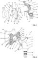
- eine perspektivische Explosionsansicht der Sanitäranordnung nach einer bevorzugten Ausführungsform, wobei ein Distanzhalter in einer ersten Relativlage gezeigt wird;
- Fig. 2
- die Ansicht nach
Figur 1 von hinten; - Fig. 3
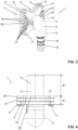
- eine perspektivische Ansicht der Ausführungsform nach den
Figuren 1 und 2 im montierten Zustand; - Fig. 4
- eine Draufsicht der
Figur 3 ; - Fig. 5
- eine Schnittdarstellung der
Figur 3 bzw. 4; - Fig. 6
- eine perspektivische Explosionsansicht der Sanitäranordnung nach der bevorzugten Ausführungsform, wobei ein Distanzhalter in einer zweiten Relativlage gezeigt wird;
- Fig. 7
- die Ansicht nach
Figur 6 von hinten; - Fig. 8
- eine perspektivische Ansicht der Ausführungsform nach den
Figuren 6 und 7 im montierten Zustand; - Fig. 9
- eine Draufsicht der
Figur 8 ; und - Fig. 10
- eine Schnittdarstellung der
Figur 8 bzw. 9. - In den Figuren wird eine bevorzugte Ausführungsform einer Sanitäranordnung 1 gezeigt. Die Sanitäranordnung 1 umfasst ein Rohranschlussstück 2 und einen Distanzhalter 9, welcher mit dem Rohranschlussstück 2 verbindbar ist. Der Distanzhalter 9 ist in zwei unterschiedlichen Relativlagen zum Rohranschlussstück 2 positionierbar. Durch die unterschiedliche Positionierung kann die Distanz zwischen einer Kontaktfläche 10 des Distanzhalters 9 und dem Rohrende 8 des Rohranschlussstücks 2 eingestellt werden.
- Das Rohranschlussstück 2 weist ein Rohrgehäuse 3 auf, welches mindestens einen Rohrkanal 4 begrenzt. Weiter weist das Rohranschlussstück 2 einen Flanschabschnitt 5 auf, welcher sich vom Rohrgehäuse 3 nach aussen hin weg erstreckt. Der Flanschabschnitt 5 weist eine Flanschfläche 6 auf. Von der Flanschfläche 6 erstreckt sich das Rohranschlussstück 2 mit einem Rohrabschnitt 7 entlang einer geraden Mittelachse M bis hin zum Rohrende 6. Der Rohrabschnitt 7 weist vorzugsweise ein Innengewinde zum Anschluss eines Rohrs auf, welches zu einem Sanitärartikel geführt werden kann. Auf der Seite, die dem Rohrabschnitt 7 gegenüberliegt, ist ein weiterer Rohrabschnitt 18 angeordnet. Der weitere Rohrabschnitt 18 hat hier die Form eines Rohrbogens, welcher den Rohrkanal 4 um 90° umlenkt. Der weitere Rohrabschnitt 18 kann aber auch anderweitig ausgebildet sein. Beispielsweise als gerade verlaufender Rohrabschnitt, als T-Stück, etc. Vorzugsweise weist der weitere Rohrabschnitt 18 eine Presskontur 19 auf, über welche das Rohranschlussstück 2 mit einem Rohr verbindbar ist.
- Der Distanzhalter 9 weist eine Kontaktfläche 10, eine erste Anschlagsfläche 11 und eine zweite Anschlagsfläche 12 auf. Mit der Kontaktfläche 10 kann der Distanzhalter 9 im eingebauten Zustand an einer Wandstruktur direkt oder über das unten beschriebene Dämpfungselement 20 indirekt anliegen.
- Die erste Anschlagsfläche 11 und die zweite Anschlagsfläche 12 sind in unterschiedlichen Abständen zur Kontaktfläche 20 angeordnet. Der Abstand A1 zwischen der ersten Anschlagsfläche 11 und der Kontaktfläche 10 bzw. der Lagerfläche 26 des Dämpfungselements 20 in Richtung der Flächennormalen F der Kontaktfläche 10 gesehen ist dabei unterschiedlich zum Abstand A2 zwischen der zweiten Anschlagsfläche 12 und der Kontaktfläche 10 bzw. der Lagerfläche 26 des Dämpfungselements 20. Die Abstände A1 und A2 sind in den
Figuren 4 und5 sowie 9 und 10 eingezeichnet. Der Distanzhalter 9 kann entweder mit der ersten Anschlagsfläche 11 oder mit der zweiten Anschlagsfläche 12 mit der Flanschfläche 6 in Kontakt gebracht werden, derart, dass die in Richtung der Mittelachse M gesehene Distanz D1 zwischen der Kontaktfläche 10 des Distanzhalters 9 bzw. der Lagerfläche 26 des Dämpfungselements 20 und dem Rohrende 8 bei der Kontaktierung mit der ersten Anschlagsfläche 11 unterschiedlich von der in Richtung der Mittelachse M gesehenen Distanz D2 zwischen der Kontaktfläche 10 des Distanzhalters 9 bzw. der Lagerfläche 26 des Dämpfungselements 20 und dem Rohrende 8 bei der Kontaktierung mit der zweiten Anschlagfläche 12 ist. In denFiguren 1 bis 5 wird die Kontaktierung über die erste Kontaktfläche 11 und in denFiguren 6 bis 10 wird die Kontaktierung über die zweite Kontaktfläche 12 gezeigt. Die Distanzen D1 und D2 sind in denFiguren 4 und5 sowie 9 und 10 eingezeichnet. - In einer Wandanordnung ist es wünschenswert, dass die Distanzen D1 und D2 im Wesentlichen der Wanddicke einer Wandstruktur W, durch welche der Rohrabschnitt 7 hindurchgeführt wird, entsprechen. Folglich kann je nach Relativlage des Distanzhalters 9 die Distanz D1 und D2 der Wandstärke entsprechend eingestellt werden.
- Der Distanzhalter 9 ist vorzugsweise aus Kunststoff hergestellt. In der gezeigten Ausführungsform weist der Distanzhalter 9 eine zentrale Öffnung 13 auf, durch welche der Rohrabschnitt 7 hindurchgeführt werden kann.
- In der gezeigten Ausführungsform wird die erste Anschlagsfläche 11 durch die Rückseite des Distanzhalters 9 gegenüber der Kontaktfläche 10 bereitgestellt. Die zweite Anschlagsfläche 12 ist Teil einer Erhebung 14, welche sich von der ersten Anschlagsfläche 11 weg erstreckt. In der gezeigten Ausführungsform sind zwei Erhebungen 14 angeordnet, welche bezüglich der Mittelachse M bzw. der zentralen Öffnung 13 einander diametral gegenüberliegen. Die Erhebungen 14 weist weiter eine Vielzahl von Einschnitten 22 auf, welche sich von der zweiten Anschlagsfläche 12 her in die Erhebungen 14 hineinerstrecken. Die zweite Anschlagsfläche 12 wird in der gezeigten Ausführungsform durch eine Vielzahl von Flächenabschnitten bereitgestellt.
- In der gezeigten Ausführungsform weist der Flanschabschnitt 5 mindestens eine, hier vier, Ausnehmungen 15 auf. Die mindestens eine Ausnehmung 15 und die mindestens eine Erhebung 14 sind dabei derart ausgebildet, dass
- in der ersten Relativlage die Erhebung 14 in die mindestens eine Ausnehmung 16 einragt, und die erste Anschlagsfläche 11 mit der Flanschfläche 6 in Kontakt bringbar ist, und
- in der zweiten Relativlage die Erhebung 14 mit der zweiten Anschlagsfläche 12 mit der Flanschfläche 6 in Kontakt bringbar ist.
- Wie eingangs erläutert zeigen die
Figuren 1 bis 5 die erste Relativlage zwischen Distanzhalter 9 und Flanschabschnitt 5 und dieFiguren 6 bis 10 zeigen die zweite Relativlage zwischen Distanzhalter 9 und Flanschabschnitt 5. - In der gezeigten Ausführungsform sind, wie erwähnt, vier Ausnehmungen vorhanden, nämlich zwei erste Ausnehmungen 15 und zwei zweite Ausnehmungen 16. Dabei sind jeweils zwei erste Ausnehmungen 15 gegenübereinander angeordnet und zwei zweite Ausnehmungen 16 sind ebenfalls gegenübereinander angeordnet. Die ersten Ausnehmungen 15 weisen dabei eine andere Form als die zweiten Ausnehmungen 16 auf. In der ersten Relativlage zwischen Distanzhalter 9 und Flanschabschnitt 5 ist die Erhebung 14 mit der zweiten Anschlagsfläche 12 und die zweite Ausnehmung 16 so ausgebildet, dass die Erhebung 14 in die zweite Ausnehmung 16 einragt, und die erste Anschlagsfläche 11 dann mit der Kontaktfläche 10 in Kontakt bringbar ist. In der zweiten Relativlage zwischen Distanzhalter 9 und Flanschabschnitt 5 ist die Erhebung 14 mit der zweiten Anschlagsfläche 12 und die erste Ausnehmung 15 so ausgebildet, dass die zweite Anschlagsfläche 12 nicht in den Bereich der ersten Ausnehmung 11 zu liegen kommt, sondern mit der Flanschfläche 6 in Kontakt bringbar ist. Die Ausnehmungen 15, 16 sind vorzugsweise in jeweiligen Winkelsegmenten angeordnet. Vorzugsweise sind vier Winkelsegmente von jeweils 90° vorhanden und in jedem der Winkelsegmente ist jeweils je eine Ausnehmung 15, 16 angeordnet.
- Der Distanzhalter 9 weist in der gezeigten Ausführungsform zwei Ausnehmungen 23 auf, welche gegenüberliegend zueinander angeordnet sind.
- Der Flanschabschnitt 5 und der Distanzhalter 9 weisen mehrere Durchgangsöffnungen 17 auf. Das Lochbild der Durchgangsöffnungen 17 im Flanschabschnitt 5 ist dabei passend zum Lochbild der Durchgangsöffnungen 17 im Distanzhalter 9 ausgebildet, so dass die beiden Lochbilder in jeder Relativlage zueinander übereinstimmen. Über die Durchgangsöffnungen 17 ist ein Befestigungselement zur Befestigung der Sanitäranordnung 1 an einer Tragstruktur hindurchführbar.
- In der gezeigten Ausführungsform weist die Sanitäranordnung weiterhin ein Dämpfungselement 20 auf, welches auf die Kontaktfläche des Distanzhalters 9 auflegbar ist. Das Dämpfungselement 20 weist eine Dicke von 2 bis 4 Millimeter auf.
- Die Distanz D1, D2 zwischen der Lagerfläche 26 des Dämpfungselements 20 und dem Rohrende 8 ist
- bei der Kontaktierung zwischen der Flanschfläche 6 und der ersten Anschlagsfläche 11 im Bereich von 31 bis 33 Millimetern und
- bei der Kontaktierung zwischen der Flanschfläche 6 und der zweiten Anschlagsfläche 12 im Bereich von 29 bis 31 Millimetern ist.
- Der Umriss der Kontaktfläche 10 in Richtung der Flächennormalen der Kontaktfläche 10 gesehen und der Umriss des Dämpfungselements 20 in die gleiche Richtung gesehen weisen die gleiche Form auf. Ferner weisen das Dämpfungselement 20 und die Kontaktfläche 10 je ein Codierungselement 21 auf, so dass das Dämpfungselement 20 in einer ausgerichteten und determinierten Lage auf die Kontaktfläche 10 auflegbar ist. In der gezeigten Variante ist das Codierungselement 21 auf Seiten des Dämpfungselements eine Ausnehmung und auf Seiten des Distanzhalters ist das Codierungselement 21 eine Nocke.
- Bei einer direkten Auflage ohne Dämpfungselement 20 werden die gleichen Distanzen D1, D2 vorgesehen, wobei dann der Rohrabschnitt 7 kürzer ausgebildet ist.
- In den
Figuren 5 und10 wird weiterhin eine Wandstruktur W gezeigt. Die Wandstruktur W ist dabei Teil einer Wandanordnung, welche weiter die Sanitäranordnung 1 nach obiger Beschreibung umfasst. Die Wandstruktur W weist eine Frontseite 24 und eine Rückseite 25 auf. Der Rohrabschnitt 7 erstreckt sich mit dem Rohrende 8 durch die Wandstruktur W hindurch. Das Rohrende 8 kommt vorzugsweise bündig mit der Frontseite 24 zu liegen. Die Sanitäranordnung 1 liegt über das Dämpfungselement 20 in indirektem Kontakt mit der Rückseite 25. - Bei einem Verfahren zur Montage der Wandanordnung wird in einem ersten Schritt die Distanz zwischen der Frontseite und der Rückseite ermittelt, dass in einem nachfolgenden Schritt der Distanzhalter 9 basierend auf der ermittelten Distanz entweder mit der ersten Anschlagsfläche 11 oder mit der zweiten Anschlagsfläche 12 zur Flanschfläche 6 hin mit dem Rohranschlussstück 2 verbunden wird, und dass in einem weiteren Schritt die Sanitäranordnung mit dem Rohrabschnitt 7 durch die Wandstruktur geführt wird, bis die Kontaktfläche 10 auf der Rückseite anliegt.
-
1 Sanitäranordnung D1 Distanz 2 Rohranschlussstück D2 Distanz 3 Rohrgehäuse M Mittelachse 4 Rohrkanal W Wandstruktur 5 Flanschabschnitt 6 Flanschfläche 7 Rohrabschnitt 8 Rohrende 9 Distanzhalter 10 Kontaktfläche 11 erste Anschlagsfläche 12 zweite Anschlagsfläche 13 zentrale Öffnung 14 Erhebung 15 erste Ausnehmung 16 zweite Ausnehmung 17 Durchgangsöffnungen 18 weiterer Rohrabschnitt 19 Presskontur 20 Dämpfungselement 21 Codierungselement 22 Einschnitte 23 Ausnehmungen 24 Frontseite 25 Rückseite 26 Lagerfläche A1 Abstand A2 Abstand
Claims (16)
- Sanitäranordnung (1) umfassendein Rohranschlussstück (2) mit einem Rohrgehäuse (3), das mindestens einen Rohrkanal (4) begrenzt, und einem vom Rohrgehäuse (3) abstehenden Flanschabschnitt (5) mit einer Flanschfläche (6), wobei sich das Rohranschlussstück (2) von der Flanschfläche (6) mit einem sich entlang einer geraden Mittelachse (M) erstreckenden Rohrabschnitt (7) bis zu einem Rohrende (8) erstreckt, undeinen Distanzhalter (9) mit einer Kontaktfläche (10) zur direkten oder indirekten Lagerung des Distanzhalters (9) auf einer Wandstruktur, sowie mit einer ersten Anschlagsfläche (11) und mit einer zweiten Anschlagsfläche (12),wobei der Abstand (A1) zwischen der ersten Anschlagsfläche (11) und der Kontaktfläche (10) in Richtung der Flächennormalen (F) der Kontaktfläche (10) gesehen unterschiedlich zum Abstand (A2) zwischen der zweiten Anschlagsfläche (12) und der Kontaktfläche (10) ist,wobei der Distanzhalter (9) entweder mit der ersten Anschlagsfläche (11) oder mit der zweiten Anschlagsfläche (12) mit der Flanschfläche (6) in Kontakt gebracht werden kann, derart,dass die in Richtung der Mittelachse (M) gesehene Distanz (D1) zwischen der Kontaktfläche (10) des Distanzhalters (9) und dem Rohrende (8) bei der Kontaktierung mit der ersten Anschlagsfläche (11) unterschiedlich von der in Richtung der Mittelachse (M) gesehenen Distanz (D2) zwischen der Kontaktfläche (10) des Distanzhalters (9) und dem Rohrende (8) bei der Kontaktierung mit der zweiten Anschlagfläche (12) ist.
- Sanitäranordnung (1) nach Anspruch 1, dadurch gekennzeichnet, dass der Distanzhalter (9) eine zentrale Öffnung (13) aufweist, durch welche der Rohrabschnitt (7) hindurchgeführt wird.
- Sanitäranordnung (1) nach einem der vorhergehenden Ansprüche, dadurch gekennzeichnet, dass die zweite Anschlagsfläche (12) durch mindestens eine Erhebung (14), die von der ersten Anschlagsfläche (11) absteht, bereitgestellt wird.
- Sanitäranordnung (1) nach Anspruch 3, dadurch gekennzeichnet, dass die mindestens eine Erhebung (14) eine Vielzahl von Einschnitten (22) aufweist, wobei die Einschnitte (22) sich vorzugsweise bis zur ersten Anschlagsfläche (11) hin erstrecken.
- Sanitäranordnung (1) nach Anspruch 3 oder 4, dadurch gekennzeichnet, dass bezüglich der Mittelachse (M) gesehen zwei Erhebungen (14) gegenüber einander angeordnet sind, wobei jede der Erhebungen (14) jeweils mindestens einen Flächenabschnitt aufweist, welcher einen Teil der zweiten Anschlagsfläche (12) bereitstellt.
- Sanitäranordnung (1) nach einem der Ansprüche 3 bis 5, dadurch gekennzeichnet, dass der Flanschabschnitt (5) mindestens eine Ausnehmung (15, 16) aufweist, wobei die Ausnehmung (15, 16) und die mindestens eine Erhebung (14) derart ausgebildet sind,dass in einer ersten Relativlage zwischen Distanzhalter (9) und Flanschabschnitt (5) die Erhebung (14) in die Ausnehmung (15, 16) einragt, und die erste Anschlagsfläche (11) mit der Flanschfläche (6) in Kontakt bringbar ist, unddass in einer zweiten Relativlage zwischen Distanzhalter (9) und Flanschabschnitt (5) die Erhebung (14) mit der zweiten Anschlagsfläche (12) mit der Flanschfläche (6) in Kontakt bringbar ist.
- Sanitäranordnung (1) nach einem der vorhergehenden Ansprüche, dadurch gekennzeichnet, dass der Distanzhalter (9) weiter zwei gegenüberliegend zueinander angeordnete Ausnehmungen (23) aufweist.
- Sanitäranordnung (1) nach einem der vorhergehenden Ansprüche, dadurch gekennzeichnet, dass der Flanschabschnitt (5) und der Distanzhalter (9) mehrere Durchgangsöffnungen (17) aufweisen, durch welche ein Befestigungselement zur Befestigung der Sanitäranordnung (1) an einer Tragstruktur hindurchführbar ist.
- Sanitäranordnung (1) nach einem der vorhergehenden Ansprüche, dadurch gekennzeichnet, dass auf der dem Rohrabschnitt (7) gegenüberliegenden Seite das Rohranschlussstück (2) mindestens einen weiteren Rohrabschnitt (18) aufweist, wobei der weitere Rohrabschnitt (18) vorzugsweise eine Presskontur (19) umfasst, über welche das Rohranschlussstück (2) mit einem Rohr verbindbar ist.
- Sanitäranordnung (1) nach einem der vorhergehenden Ansprüche, dadurch gekennzeichnet, dass mindestens eine der genannten Anschlagsflächen (11, 12) durch mehrere Flächenabschnitte (5) bereitgestellt wird; und/oder dass mindestens eine der genannten Anschlagsflächen (11, 12) durch eine durchgehende Fläche bereitgestellt wird.
- Sanitäranordnung (1) nach einem der vorhergehenden Ansprüche, dadurch gekennzeichnet, dass die Sanitäranordnung (1) weiterhin ein Dämpfungselement (20) aufweist, welches auf die Kontaktfläche (10) des Distanzhalters (9) auflegbar ist, und dass das Dämpfungselement eine Lagerfläche (26) aufweist, mit welcher das Dämpfungselement auf einer Wandstruktur aufliegen kann.
- Sanitäranordnung (1) nach Anspruch 11, dadurch gekennzeichnet, dass der Umriss der Kontaktfläche (10) in Richtung der Flächennormalen der Kontaktfläche (10) gesehen und der Umriss des Dämpfungselements (20) in die gleiche Richtung gesehen die gleiche Form aufweisen; und/oder dass das Dämpfungselement (20) und die Kontaktfläche (10) je ein Codierungselement (21) aufweisen, so dass das Dämpfungselement (20) in einer ausgerichteten und determinierten Lage auf die Kontaktfläche (10) auflegbar ist.
- Sanitäranordnung (1) nach einem der vorhergehenden Ansprüche, dadurch gekennzeichnet, dass die Distanz (D1, D2) zwischen der Lagerfläche (26) des Dämpfungselements (20) und dem Rohrende (8)bei der Kontaktierung zwischen der Flanschfläche (6) und der ersten Anschlagsfläche (11) im Bereich von 31 bis 33 Millimetern undbei der Kontaktierung zwischen der Flanschfläche (6) und der zweiten Anschlagsfläche (12) im Bereich von 26 bis 29 Millimetern ist.
- Sanitäranordnung (1) nach einem der vorhergehenden Ansprüche 1 bis 10, dadurch gekennzeichnet, dass die Distanz (D1, D2) zwischen der Kontaktfläche (10) des Distanzhalters (9) und dem Rohrende (8)bei der Kontaktierung zwischen der Flanschfläche (6) und der ersten Anschlagsfläche (11) im Bereich von 34 bis 36 Millimetern undbei der Kontaktierung zwischen der Flanschfläche (6) und der zweiten Anschlagsfläche (12) im Bereich von 29 bis 31 Millimetern ist.
- Wandanordnung umfassend eine Sanitäranordnung (1) nach einem der vorhergehenden Ansprüche und eine Wandstruktur mit einer Frontseite und einer Rückseite, wobei der Distanzhalter (9) mit der Kontaktfläche (10) direkt oder indirekt auf der Rückseite aufliegt und wobei sich der Rohrabschnitt (7) mit dem Rohrende (8) durch die Wandstruktur hindurcherstreckt, wobei das Rohrende (8) vorzugsweise bündig zur Frontseite zu liegen kommt.
- Verfahren zur Montage einer Wandanordnung nach Anspruch 14, dadurch gekennzeichnet, dass in einem ersten Schritt die Distanz zwischen der Frontseite und der Rückseite ermittelt wird, dass in einem nachfolgenden Schritt der Distanzhalter (9) basierend auf der ermittelten Distanz entweder mit der ersten Anschlagsfläche (11) oder mit der zweiten Anschlagsfläche (12) zur Flanschfläche (6) hin mit dem Rohranschlussstück (2) verbunden wird, und dass in einem weiteren Schritt die Sanitäranordnung mit dem Rohrabschnitt (7) durch die Wandstruktur geführt wird, bis die Kontaktfläche (10) auf der Rückseite anliegt.
Priority Applications (2)
| Application Number | Priority Date | Filing Date | Title |
|---|---|---|---|
| EP21216752.2A EP4202132B1 (de) | 2021-12-22 | 2021-12-22 | Sanitäranordnung, wandanordnung umfassend eine solche sanitäranordnung und verfahren zur montage einer solchen wandanordnung |
| CN202211502564.6A CN116335239A (zh) | 2021-12-22 | 2022-11-28 | 洁具装置 |
Applications Claiming Priority (1)
| Application Number | Priority Date | Filing Date | Title |
|---|---|---|---|
| EP21216752.2A EP4202132B1 (de) | 2021-12-22 | 2021-12-22 | Sanitäranordnung, wandanordnung umfassend eine solche sanitäranordnung und verfahren zur montage einer solchen wandanordnung |
Publications (2)
| Publication Number | Publication Date |
|---|---|
| EP4202132A1 true EP4202132A1 (de) | 2023-06-28 |
| EP4202132B1 EP4202132B1 (de) | 2025-04-09 |
Family
ID=79025123
Family Applications (1)
| Application Number | Title | Priority Date | Filing Date |
|---|---|---|---|
| EP21216752.2A Active EP4202132B1 (de) | 2021-12-22 | 2021-12-22 | Sanitäranordnung, wandanordnung umfassend eine solche sanitäranordnung und verfahren zur montage einer solchen wandanordnung |
Country Status (2)
| Country | Link |
|---|---|
| EP (1) | EP4202132B1 (de) |
| CN (1) | CN116335239A (de) |
Cited By (1)
| Publication number | Priority date | Publication date | Assignee | Title |
|---|---|---|---|---|
| DE102024131734A1 (de) | 2024-10-30 | 2026-04-30 | Viega Technology Gmbh & Co. Kg | Wanddurchführung |
Citations (5)
| Publication number | Priority date | Publication date | Assignee | Title |
|---|---|---|---|---|
| EP0824170B1 (de) * | 1996-08-13 | 2000-07-05 | POLYTHERM VERTRIEBSGESELLSCHAFT HAUSTECHNISCHER ARTIKEL mbH | Befestigungsvorrichtung für einen zur Wandmontage von sanitären Elementen verwendeten Anchlussfitting |
| EP1348815A1 (de) | 2002-03-28 | 2003-10-01 | Gripp | Anordnung, Verfahren und Vorrichtung für Montage und Anschluss einer sanitären Installationsleitung |
| KR200382026Y1 (ko) * | 2005-02-01 | 2005-04-18 | 강철 | 수전이음쇠의 고정장치 |
| CN105780870A (zh) * | 2016-04-22 | 2016-07-20 | 中冶天工集团天津有限公司 | 用于控制暗敷管道预留丝头出墙长度的控制装置及方法 |
| EP3477007A1 (de) * | 2017-10-31 | 2019-05-01 | Hesperia Developpement | Montageverfahren eines befestigungskits eines hahns an einer trennwand, insbesondere einer trennwand aus gipskartonplatten |
-
2021
- 2021-12-22 EP EP21216752.2A patent/EP4202132B1/de active Active
-
2022
- 2022-11-28 CN CN202211502564.6A patent/CN116335239A/zh active Pending
Patent Citations (5)
| Publication number | Priority date | Publication date | Assignee | Title |
|---|---|---|---|---|
| EP0824170B1 (de) * | 1996-08-13 | 2000-07-05 | POLYTHERM VERTRIEBSGESELLSCHAFT HAUSTECHNISCHER ARTIKEL mbH | Befestigungsvorrichtung für einen zur Wandmontage von sanitären Elementen verwendeten Anchlussfitting |
| EP1348815A1 (de) | 2002-03-28 | 2003-10-01 | Gripp | Anordnung, Verfahren und Vorrichtung für Montage und Anschluss einer sanitären Installationsleitung |
| KR200382026Y1 (ko) * | 2005-02-01 | 2005-04-18 | 강철 | 수전이음쇠의 고정장치 |
| CN105780870A (zh) * | 2016-04-22 | 2016-07-20 | 中冶天工集团天津有限公司 | 用于控制暗敷管道预留丝头出墙长度的控制装置及方法 |
| EP3477007A1 (de) * | 2017-10-31 | 2019-05-01 | Hesperia Developpement | Montageverfahren eines befestigungskits eines hahns an einer trennwand, insbesondere einer trennwand aus gipskartonplatten |
Cited By (2)
| Publication number | Priority date | Publication date | Assignee | Title |
|---|---|---|---|---|
| DE102024131734A1 (de) | 2024-10-30 | 2026-04-30 | Viega Technology Gmbh & Co. Kg | Wanddurchführung |
| EP4737654A1 (de) | 2024-10-30 | 2026-05-06 | Viega Technology GmbH & Co. KG | Wanddurchführung |
Also Published As
| Publication number | Publication date |
|---|---|
| EP4202132B1 (de) | 2025-04-09 |
| CN116335239A (zh) | 2023-06-27 |
Similar Documents
| Publication | Publication Date | Title |
|---|---|---|
| EP3746609B1 (de) | Anschlussvorrichtung für eine toilettenschüssel | |
| DE102004021245B4 (de) | Abstandshalter (Spacer) für koaxial ummantelte Kraftstoffrohre | |
| EP4202132B1 (de) | Sanitäranordnung, wandanordnung umfassend eine solche sanitäranordnung und verfahren zur montage einer solchen wandanordnung | |
| EP1834090A1 (de) | Kolbenpumpe, insbesondere hochdruck-kraftstoffpumpe f]r eine brennkraftmaschine eines kraftfahrzeugs | |
| EP3064663B1 (de) | Sanitäreinrichtung | |
| EP2837861B1 (de) | Absperrventilgehäuse und Absperrventil | |
| EP3695748B1 (de) | Einbauschrankanordnung | |
| EP3825481B1 (de) | Spülwasserverteiler | |
| EP1812167B1 (de) | Strahlaustrittselement für sanitärarmaturen | |
| EP3913758B1 (de) | Hohlwanddose | |
| DE102016124797A1 (de) | Vorrichtung zur Befestigung an einem Befestigungsvorsprung eines Trägerbauteils | |
| EP3896234B1 (de) | Armaturenanordnung | |
| EP4399371B1 (de) | Montagevorrichtung für einen sanitärartikel | |
| EP4080069B1 (de) | System zur befestigung | |
| EP3708727B1 (de) | Sanitärartikelanordnung und verfahren zur montage dieser | |
| EP4223946B1 (de) | Montagesystem für sanitärartikel | |
| EP4259882B1 (de) | Montagevorrichtung | |
| DE20105250U1 (de) | Flachdichtung | |
| EP3964655B1 (de) | Befestigungselement | |
| EP3933129A1 (de) | Sanitäres installationssystem | |
| EP4474658B1 (de) | Wandankeranordnung | |
| EP3933130B1 (de) | Sanitäres installationssystem | |
| EP4194625B1 (de) | Rohranschlussanordnung | |
| EP4043655A1 (de) | Fusseinheit und montagevorrichtung mit solch einer fusseinheit | |
| EP4600509A1 (de) | Verbindungselement |
Legal Events
| Date | Code | Title | Description |
|---|---|---|---|
| PUAI | Public reference made under article 153(3) epc to a published international application that has entered the european phase |
Free format text: ORIGINAL CODE: 0009012 |
|
| STAA | Information on the status of an ep patent application or granted ep patent |
Free format text: STATUS: THE APPLICATION HAS BEEN PUBLISHED |
|
| AK | Designated contracting states |
Kind code of ref document: A1 Designated state(s): AL AT BE BG CH CY CZ DE DK EE ES FI FR GB GR HR HU IE IS IT LI LT LU LV MC MK MT NL NO PL PT RO RS SE SI SK SM TR |
|
| STAA | Information on the status of an ep patent application or granted ep patent |
Free format text: STATUS: REQUEST FOR EXAMINATION WAS MADE |
|
| 17P | Request for examination filed |
Effective date: 20231030 |
|
| RBV | Designated contracting states (corrected) |
Designated state(s): AL AT BE BG CH CY CZ DE DK EE ES FI FR GB GR HR HU IE IS IT LI LT LU LV MC MK MT NL NO PL PT RO RS SE SI SK SM TR |
|
| RAP1 | Party data changed (applicant data changed or rights of an application transferred) |
Owner name: GEBERIT INTERNATIONAL AG |
|
| GRAP | Despatch of communication of intention to grant a patent |
Free format text: ORIGINAL CODE: EPIDOSNIGR1 |
|
| STAA | Information on the status of an ep patent application or granted ep patent |
Free format text: STATUS: GRANT OF PATENT IS INTENDED |
|
| INTG | Intention to grant announced |
Effective date: 20241112 |
|
| GRAS | Grant fee paid |
Free format text: ORIGINAL CODE: EPIDOSNIGR3 |
|
| GRAA | (expected) grant |
Free format text: ORIGINAL CODE: 0009210 |
|
| STAA | Information on the status of an ep patent application or granted ep patent |
Free format text: STATUS: THE PATENT HAS BEEN GRANTED |
|
| AK | Designated contracting states |
Kind code of ref document: B1 Designated state(s): AL AT BE BG CH CY CZ DE DK EE ES FI FR GB GR HR HU IE IS IT LI LT LU LV MC MK MT NL NO PL PT RO RS SE SI SK SM TR |
|
| P01 | Opt-out of the competence of the unified patent court (upc) registered |
Free format text: CASE NUMBER: APP_65898/2024 Effective date: 20250227 |
|
| REG | Reference to a national code |
Ref country code: GB Ref legal event code: FG4D Free format text: NOT ENGLISH |
|
| REG | Reference to a national code |
Ref country code: CH Ref legal event code: EP |
|
| REG | Reference to a national code |
Ref country code: DE Ref legal event code: R096 Ref document number: 502021007160 Country of ref document: DE |
|
| REG | Reference to a national code |
Ref country code: IE Ref legal event code: FG4D Free format text: LANGUAGE OF EP DOCUMENT: GERMAN |
|
| REG | Reference to a national code |
Ref country code: NL Ref legal event code: MP Effective date: 20250409 |
|
| PG25 | Lapsed in a contracting state [announced via postgrant information from national office to epo] |
Ref country code: NL Free format text: LAPSE BECAUSE OF FAILURE TO SUBMIT A TRANSLATION OF THE DESCRIPTION OR TO PAY THE FEE WITHIN THE PRESCRIBED TIME-LIMIT Effective date: 20250409 |
|
| PG25 | Lapsed in a contracting state [announced via postgrant information from national office to epo] |
Ref country code: PT Free format text: LAPSE BECAUSE OF FAILURE TO SUBMIT A TRANSLATION OF THE DESCRIPTION OR TO PAY THE FEE WITHIN THE PRESCRIBED TIME-LIMIT Effective date: 20250811 Ref country code: ES Free format text: LAPSE BECAUSE OF FAILURE TO SUBMIT A TRANSLATION OF THE DESCRIPTION OR TO PAY THE FEE WITHIN THE PRESCRIBED TIME-LIMIT Effective date: 20250409 Ref country code: FI Free format text: LAPSE BECAUSE OF FAILURE TO SUBMIT A TRANSLATION OF THE DESCRIPTION OR TO PAY THE FEE WITHIN THE PRESCRIBED TIME-LIMIT Effective date: 20250409 |
|
| REG | Reference to a national code |
Ref country code: LT Ref legal event code: MG9D |
|
| PG25 | Lapsed in a contracting state [announced via postgrant information from national office to epo] |
Ref country code: NO Free format text: LAPSE BECAUSE OF FAILURE TO SUBMIT A TRANSLATION OF THE DESCRIPTION OR TO PAY THE FEE WITHIN THE PRESCRIBED TIME-LIMIT Effective date: 20250709 Ref country code: GR Free format text: LAPSE BECAUSE OF FAILURE TO SUBMIT A TRANSLATION OF THE DESCRIPTION OR TO PAY THE FEE WITHIN THE PRESCRIBED TIME-LIMIT Effective date: 20250710 |
|
| PG25 | Lapsed in a contracting state [announced via postgrant information from national office to epo] |
Ref country code: PL Free format text: LAPSE BECAUSE OF FAILURE TO SUBMIT A TRANSLATION OF THE DESCRIPTION OR TO PAY THE FEE WITHIN THE PRESCRIBED TIME-LIMIT Effective date: 20250409 |
|
| PG25 | Lapsed in a contracting state [announced via postgrant information from national office to epo] |
Ref country code: BG Free format text: LAPSE BECAUSE OF FAILURE TO SUBMIT A TRANSLATION OF THE DESCRIPTION OR TO PAY THE FEE WITHIN THE PRESCRIBED TIME-LIMIT Effective date: 20250409 |
|
| PG25 | Lapsed in a contracting state [announced via postgrant information from national office to epo] |
Ref country code: HR Free format text: LAPSE BECAUSE OF FAILURE TO SUBMIT A TRANSLATION OF THE DESCRIPTION OR TO PAY THE FEE WITHIN THE PRESCRIBED TIME-LIMIT Effective date: 20250409 |
|
| PG25 | Lapsed in a contracting state [announced via postgrant information from national office to epo] |
Ref country code: RS Free format text: LAPSE BECAUSE OF FAILURE TO SUBMIT A TRANSLATION OF THE DESCRIPTION OR TO PAY THE FEE WITHIN THE PRESCRIBED TIME-LIMIT Effective date: 20250709 |
|
| PG25 | Lapsed in a contracting state [announced via postgrant information from national office to epo] |
Ref country code: IS Free format text: LAPSE BECAUSE OF FAILURE TO SUBMIT A TRANSLATION OF THE DESCRIPTION OR TO PAY THE FEE WITHIN THE PRESCRIBED TIME-LIMIT Effective date: 20250809 |
|
| PG25 | Lapsed in a contracting state [announced via postgrant information from national office to epo] |
Ref country code: LV Free format text: LAPSE BECAUSE OF FAILURE TO SUBMIT A TRANSLATION OF THE DESCRIPTION OR TO PAY THE FEE WITHIN THE PRESCRIBED TIME-LIMIT Effective date: 20250409 |
|
| REG | Reference to a national code |
Ref country code: CH Ref legal event code: U11 Free format text: ST27 STATUS EVENT CODE: U-0-0-U10-U11 (AS PROVIDED BY THE NATIONAL OFFICE) Effective date: 20260101 |
|
| PGFP | Annual fee paid to national office [announced via postgrant information from national office to epo] |
Ref country code: DE Payment date: 20251211 Year of fee payment: 5 |
|
| REG | Reference to a national code |
Ref country code: DE Ref legal event code: R097 Ref document number: 502021007160 Country of ref document: DE |
|
| PG25 | Lapsed in a contracting state [announced via postgrant information from national office to epo] |
Ref country code: DK Free format text: LAPSE BECAUSE OF FAILURE TO SUBMIT A TRANSLATION OF THE DESCRIPTION OR TO PAY THE FEE WITHIN THE PRESCRIBED TIME-LIMIT Effective date: 20250409 Ref country code: SM Free format text: LAPSE BECAUSE OF FAILURE TO SUBMIT A TRANSLATION OF THE DESCRIPTION OR TO PAY THE FEE WITHIN THE PRESCRIBED TIME-LIMIT Effective date: 20250409 |
|
| PGFP | Annual fee paid to national office [announced via postgrant information from national office to epo] |
Ref country code: AT Payment date: 20260113 Year of fee payment: 5 |
|
| PGFP | Annual fee paid to national office [announced via postgrant information from national office to epo] |
Ref country code: BE Payment date: 20251219 Year of fee payment: 5 |
|
| PG25 | Lapsed in a contracting state [announced via postgrant information from national office to epo] |
Ref country code: CZ Free format text: LAPSE BECAUSE OF FAILURE TO SUBMIT A TRANSLATION OF THE DESCRIPTION OR TO PAY THE FEE WITHIN THE PRESCRIBED TIME-LIMIT Effective date: 20250409 |
|
| PG25 | Lapsed in a contracting state [announced via postgrant information from national office to epo] |
Ref country code: EE Free format text: LAPSE BECAUSE OF FAILURE TO SUBMIT A TRANSLATION OF THE DESCRIPTION OR TO PAY THE FEE WITHIN THE PRESCRIBED TIME-LIMIT Effective date: 20250409 |
|
| PG25 | Lapsed in a contracting state [announced via postgrant information from national office to epo] |
Ref country code: SK Free format text: LAPSE BECAUSE OF FAILURE TO SUBMIT A TRANSLATION OF THE DESCRIPTION OR TO PAY THE FEE WITHIN THE PRESCRIBED TIME-LIMIT Effective date: 20250409 |
|
| PG25 | Lapsed in a contracting state [announced via postgrant information from national office to epo] |
Ref country code: IT Free format text: LAPSE BECAUSE OF FAILURE TO SUBMIT A TRANSLATION OF THE DESCRIPTION OR TO PAY THE FEE WITHIN THE PRESCRIBED TIME-LIMIT Effective date: 20250409 |
|
| PLBE | No opposition filed within time limit |
Free format text: ORIGINAL CODE: 0009261 |
|
| STAA | Information on the status of an ep patent application or granted ep patent |
Free format text: STATUS: NO OPPOSITION FILED WITHIN TIME LIMIT |
|
| REG | Reference to a national code |
Ref country code: CH Ref legal event code: L10 Free format text: ST27 STATUS EVENT CODE: U-0-0-L10-L00 (AS PROVIDED BY THE NATIONAL OFFICE) Effective date: 20260218 |
|
| PG25 | Lapsed in a contracting state [announced via postgrant information from national office to epo] |
Ref country code: RO Free format text: LAPSE BECAUSE OF FAILURE TO SUBMIT A TRANSLATION OF THE DESCRIPTION OR TO PAY THE FEE WITHIN THE PRESCRIBED TIME-LIMIT Effective date: 20250409 |
|
| 26N | No opposition filed |
Effective date: 20260112 |
|
| PGFP | Annual fee paid to national office [announced via postgrant information from national office to epo] |
Ref country code: CH Payment date: 20260101 Year of fee payment: 5 |