EP4201896A1 - Glass tube for pharmaceutical containers and process for the production of a glass tube - Google Patents
Glass tube for pharmaceutical containers and process for the production of a glass tube Download PDFInfo
- Publication number
- EP4201896A1 EP4201896A1 EP21216969.2A EP21216969A EP4201896A1 EP 4201896 A1 EP4201896 A1 EP 4201896A1 EP 21216969 A EP21216969 A EP 21216969A EP 4201896 A1 EP4201896 A1 EP 4201896A1
- Authority
- EP
- European Patent Office
- Prior art keywords
- glass tube
- glass
- signal
- mol
- less
- Prior art date
- Legal status (The legal status is an assumption and is not a legal conclusion. Google has not performed a legal analysis and makes no representation as to the accuracy of the status listed.)
- Pending
Links
- 239000011521 glass Substances 0.000 title claims abstract description 373
- 238000000034 method Methods 0.000 title claims abstract description 36
- 238000004519 manufacturing process Methods 0.000 title claims abstract description 22
- 239000000203 mixture Substances 0.000 claims description 79
- GWEVSGVZZGPLCZ-UHFFFAOYSA-N Titan oxide Chemical compound O=[Ti]=O GWEVSGVZZGPLCZ-UHFFFAOYSA-N 0.000 claims description 42
- VYPSYNLAJGMNEJ-UHFFFAOYSA-N Silicium dioxide Chemical compound O=[Si]=O VYPSYNLAJGMNEJ-UHFFFAOYSA-N 0.000 claims description 36
- 238000009423 ventilation Methods 0.000 claims description 33
- 238000002042 time-of-flight secondary ion mass spectrometry Methods 0.000 claims description 29
- 229910052681 coesite Inorganic materials 0.000 claims description 18
- 229910052906 cristobalite Inorganic materials 0.000 claims description 18
- 239000000377 silicon dioxide Substances 0.000 claims description 18
- 229910052682 stishovite Inorganic materials 0.000 claims description 18
- 229910052905 tridymite Inorganic materials 0.000 claims description 18
- KKCBUQHMOMHUOY-UHFFFAOYSA-N Na2O Inorganic materials [O-2].[Na+].[Na+] KKCBUQHMOMHUOY-UHFFFAOYSA-N 0.000 claims description 15
- PNEYBMLMFCGWSK-UHFFFAOYSA-N aluminium oxide Inorganic materials [O-2].[O-2].[O-2].[Al+3].[Al+3] PNEYBMLMFCGWSK-UHFFFAOYSA-N 0.000 claims description 15
- 229910052593 corundum Inorganic materials 0.000 claims description 15
- JEIPFZHSYJVQDO-UHFFFAOYSA-N iron(III) oxide Inorganic materials O=[Fe]O[Fe]=O JEIPFZHSYJVQDO-UHFFFAOYSA-N 0.000 claims description 15
- 229910001845 yogo sapphire Inorganic materials 0.000 claims description 15
- 239000000156 glass melt Substances 0.000 claims description 13
- 230000008018 melting Effects 0.000 claims description 13
- 238000002844 melting Methods 0.000 claims description 13
- 150000001642 boronic acid derivatives Chemical class 0.000 claims description 10
- 230000003301 hydrolyzing effect Effects 0.000 claims description 9
- 238000012216 screening Methods 0.000 claims description 6
- 239000003513 alkali Substances 0.000 claims description 5
- 230000000694 effects Effects 0.000 claims description 5
- 238000010438 heat treatment Methods 0.000 claims description 5
- 239000002994 raw material Substances 0.000 claims description 5
- 238000007789 sealing Methods 0.000 claims description 3
- 239000005354 aluminosilicate glass Substances 0.000 claims description 2
- 239000005388 borosilicate glass Substances 0.000 claims description 2
- 239000005361 soda-lime glass Substances 0.000 claims description 2
- 239000011734 sodium Substances 0.000 description 44
- 230000005284 excitation Effects 0.000 description 36
- 238000005011 time of flight secondary ion mass spectroscopy Methods 0.000 description 28
- 239000000463 material Substances 0.000 description 23
- 150000002500 ions Chemical class 0.000 description 15
- MCMNRKCIXSYSNV-UHFFFAOYSA-N Zirconium dioxide Chemical compound O=[Zr]=O MCMNRKCIXSYSNV-UHFFFAOYSA-N 0.000 description 12
- -1 NaCI and/or NaF Chemical class 0.000 description 10
- GOLCXWYRSKYTSP-UHFFFAOYSA-N Arsenious Acid Chemical compound O1[As]2O[As]1O2 GOLCXWYRSKYTSP-UHFFFAOYSA-N 0.000 description 8
- 238000004458 analytical method Methods 0.000 description 8
- 238000005259 measurement Methods 0.000 description 8
- 238000003271 compound fluorescence assay Methods 0.000 description 6
- XLYOFNOQVPJJNP-UHFFFAOYSA-N water Substances O XLYOFNOQVPJJNP-UHFFFAOYSA-N 0.000 description 6
- 229910021538 borax Inorganic materials 0.000 description 5
- 238000011109 contamination Methods 0.000 description 5
- 239000006025 fining agent Substances 0.000 description 5
- 159000000000 sodium salts Chemical class 0.000 description 5
- 235000010339 sodium tetraborate Nutrition 0.000 description 5
- BSVBQGMMJUBVOD-UHFFFAOYSA-N trisodium borate Chemical compound [Na+].[Na+].[Na+].[O-]B([O-])[O-] BSVBQGMMJUBVOD-UHFFFAOYSA-N 0.000 description 5
- FAPWRFPIFSIZLT-UHFFFAOYSA-M Sodium chloride Chemical compound [Na+].[Cl-] FAPWRFPIFSIZLT-UHFFFAOYSA-M 0.000 description 4
- CETPSERCERDGAM-UHFFFAOYSA-N ceric oxide Chemical compound O=[Ce]=O CETPSERCERDGAM-UHFFFAOYSA-N 0.000 description 4
- 229910000422 cerium(IV) oxide Inorganic materials 0.000 description 4
- 230000008020 evaporation Effects 0.000 description 4
- 238000001704 evaporation Methods 0.000 description 4
- 239000000047 product Substances 0.000 description 4
- 229920002379 silicone rubber Polymers 0.000 description 4
- 239000004945 silicone rubber Substances 0.000 description 4
- 239000000356 contaminant Substances 0.000 description 3
- 230000010354 integration Effects 0.000 description 3
- NOTVAPJNGZMVSD-UHFFFAOYSA-N potassium monoxide Inorganic materials [K]O[K] NOTVAPJNGZMVSD-UHFFFAOYSA-N 0.000 description 3
- CHWRSCGUEQEHOH-UHFFFAOYSA-N potassium oxide Chemical compound [O-2].[K+].[K+] CHWRSCGUEQEHOH-UHFFFAOYSA-N 0.000 description 3
- 238000012360 testing method Methods 0.000 description 3
- IKWTVSLWAPBBKU-UHFFFAOYSA-N a1010_sial Chemical compound O=[As]O[As]=O IKWTVSLWAPBBKU-UHFFFAOYSA-N 0.000 description 2
- 229910000410 antimony oxide Inorganic materials 0.000 description 2
- 229910000413 arsenic oxide Inorganic materials 0.000 description 2
- 229960002594 arsenic trioxide Drugs 0.000 description 2
- 150000003841 chloride salts Chemical class 0.000 description 2
- 238000001514 detection method Methods 0.000 description 2
- 238000010884 ion-beam technique Methods 0.000 description 2
- 238000000386 microscopy Methods 0.000 description 2
- 238000012544 monitoring process Methods 0.000 description 2
- VTRUBDSFZJNXHI-UHFFFAOYSA-N oxoantimony Chemical compound [Sb]=O VTRUBDSFZJNXHI-UHFFFAOYSA-N 0.000 description 2
- 238000007670 refining Methods 0.000 description 2
- 239000011780 sodium chloride Substances 0.000 description 2
- 239000000126 substance Substances 0.000 description 2
- 150000003467 sulfuric acid derivatives Chemical class 0.000 description 2
- XOLBLPGZBRYERU-UHFFFAOYSA-N tin dioxide Chemical compound O=[Sn]=O XOLBLPGZBRYERU-UHFFFAOYSA-N 0.000 description 2
- 229910001887 tin oxide Inorganic materials 0.000 description 2
- 238000012369 In process control Methods 0.000 description 1
- 239000005030 aluminium foil Substances 0.000 description 1
- 238000003556 assay Methods 0.000 description 1
- 230000015572 biosynthetic process Effects 0.000 description 1
- 238000007664 blowing Methods 0.000 description 1
- 229910000420 cerium oxide Inorganic materials 0.000 description 1
- 150000001875 compounds Chemical class 0.000 description 1
- 238000009833 condensation Methods 0.000 description 1
- 230000005494 condensation Effects 0.000 description 1
- 239000000470 constituent Substances 0.000 description 1
- 238000005520 cutting process Methods 0.000 description 1
- 238000011157 data evaluation Methods 0.000 description 1
- 238000013461 design Methods 0.000 description 1
- 230000006866 deterioration Effects 0.000 description 1
- 238000004090 dissolution Methods 0.000 description 1
- 239000012153 distilled water Substances 0.000 description 1
- 239000003814 drug Substances 0.000 description 1
- 230000008030 elimination Effects 0.000 description 1
- 238000003379 elimination reaction Methods 0.000 description 1
- 230000003628 erosive effect Effects 0.000 description 1
- 239000012467 final product Substances 0.000 description 1
- 238000001917 fluorescence detection Methods 0.000 description 1
- 238000001506 fluorescence spectroscopy Methods 0.000 description 1
- 238000002189 fluorescence spectrum Methods 0.000 description 1
- 238000012203 high throughput assay Methods 0.000 description 1
- 238000000265 homogenisation Methods 0.000 description 1
- 239000012535 impurity Substances 0.000 description 1
- 238000010965 in-process control Methods 0.000 description 1
- 238000013507 mapping Methods 0.000 description 1
- 238000004949 mass spectrometry Methods 0.000 description 1
- 239000000155 melt Substances 0.000 description 1
- BMMGVYCKOGBVEV-UHFFFAOYSA-N oxo(oxoceriooxy)cerium Chemical compound [Ce]=O.O=[Ce]=O BMMGVYCKOGBVEV-UHFFFAOYSA-N 0.000 description 1
- 230000035515 penetration Effects 0.000 description 1
- 239000000825 pharmaceutical preparation Substances 0.000 description 1
- 229940127557 pharmaceutical product Drugs 0.000 description 1
- 238000001556 precipitation Methods 0.000 description 1
- 230000002265 prevention Effects 0.000 description 1
- 238000003908 quality control method Methods 0.000 description 1
- 238000005070 sampling Methods 0.000 description 1
- 238000000926 separation method Methods 0.000 description 1
- 230000003595 spectral effect Effects 0.000 description 1
- 238000000859 sublimation Methods 0.000 description 1
- 230000008022 sublimation Effects 0.000 description 1
- 238000005211 surface analysis Methods 0.000 description 1
- 230000003746 surface roughness Effects 0.000 description 1
- 229910052724 xenon Inorganic materials 0.000 description 1
- FHNFHKCVQCLJFQ-UHFFFAOYSA-N xenon atom Chemical compound [Xe] FHNFHKCVQCLJFQ-UHFFFAOYSA-N 0.000 description 1
Images


Classifications
-
- F—MECHANICAL ENGINEERING; LIGHTING; HEATING; WEAPONS; BLASTING
- F16—ENGINEERING ELEMENTS AND UNITS; GENERAL MEASURES FOR PRODUCING AND MAINTAINING EFFECTIVE FUNCTIONING OF MACHINES OR INSTALLATIONS; THERMAL INSULATION IN GENERAL
- F16L—PIPES; JOINTS OR FITTINGS FOR PIPES; SUPPORTS FOR PIPES, CABLES OR PROTECTIVE TUBING; MEANS FOR THERMAL INSULATION IN GENERAL
- F16L9/00—Rigid pipes
- F16L9/10—Rigid pipes of glass or ceramics, e.g. clay, clay tile, porcelain
- F16L9/105—Rigid pipes of glass or ceramics, e.g. clay, clay tile, porcelain of glass
-
- B—PERFORMING OPERATIONS; TRANSPORTING
- B65—CONVEYING; PACKING; STORING; HANDLING THIN OR FILAMENTARY MATERIAL
- B65D—CONTAINERS FOR STORAGE OR TRANSPORT OF ARTICLES OR MATERIALS, e.g. BAGS, BARRELS, BOTTLES, BOXES, CANS, CARTONS, CRATES, DRUMS, JARS, TANKS, HOPPERS, FORWARDING CONTAINERS; ACCESSORIES, CLOSURES, OR FITTINGS THEREFOR; PACKAGING ELEMENTS; PACKAGES
- B65D1/00—Containers having bodies formed in one piece, e.g. by casting metallic material, by moulding plastics, by blowing vitreous material, by throwing ceramic material, by moulding pulped fibrous material, by deep-drawing operations performed on sheet material
- B65D1/40—Details of walls
-
- C—CHEMISTRY; METALLURGY
- C03—GLASS; MINERAL OR SLAG WOOL
- C03B—MANUFACTURE, SHAPING, OR SUPPLEMENTARY PROCESSES
- C03B17/00—Forming molten glass by flowing-out, pushing-out, extruding or drawing downwardly or laterally from forming slits or by overflowing over lips
- C03B17/04—Forming tubes or rods by drawing from stationary or rotating tools or from forming nozzles
-
- B—PERFORMING OPERATIONS; TRANSPORTING
- B07—SEPARATING SOLIDS FROM SOLIDS; SORTING
- B07C—POSTAL SORTING; SORTING INDIVIDUAL ARTICLES, OR BULK MATERIAL FIT TO BE SORTED PIECE-MEAL, e.g. BY PICKING
- B07C5/00—Sorting according to a characteristic or feature of the articles or material being sorted, e.g. by control effected by devices which detect or measure such characteristic or feature; Sorting by manually actuated devices, e.g. switches
- B07C5/34—Sorting according to other particular properties
- B07C5/342—Sorting according to other particular properties according to optical properties, e.g. colour
-
- C—CHEMISTRY; METALLURGY
- C03—GLASS; MINERAL OR SLAG WOOL
- C03B—MANUFACTURE, SHAPING, OR SUPPLEMENTARY PROCESSES
- C03B23/00—Re-forming shaped glass
- C03B23/04—Re-forming tubes or rods
- C03B23/09—Reshaping the ends, e.g. as grooves, threads or mouths
- C03B23/099—Reshaping the ends, e.g. as grooves, threads or mouths by fusing, e.g. flame sealing
-
- C—CHEMISTRY; METALLURGY
- C03—GLASS; MINERAL OR SLAG WOOL
- C03C—CHEMICAL COMPOSITION OF GLASSES, GLAZES OR VITREOUS ENAMELS; SURFACE TREATMENT OF GLASS; SURFACE TREATMENT OF FIBRES OR FILAMENTS MADE FROM GLASS, MINERALS OR SLAGS; JOINING GLASS TO GLASS OR OTHER MATERIALS
- C03C3/00—Glass compositions
- C03C3/04—Glass compositions containing silica
- C03C3/076—Glass compositions containing silica with 40% to 90% silica, by weight
- C03C3/078—Glass compositions containing silica with 40% to 90% silica, by weight containing an oxide of a divalent metal, e.g. an oxide of zinc
-
- C—CHEMISTRY; METALLURGY
- C03—GLASS; MINERAL OR SLAG WOOL
- C03C—CHEMICAL COMPOSITION OF GLASSES, GLAZES OR VITREOUS ENAMELS; SURFACE TREATMENT OF GLASS; SURFACE TREATMENT OF FIBRES OR FILAMENTS MADE FROM GLASS, MINERALS OR SLAGS; JOINING GLASS TO GLASS OR OTHER MATERIALS
- C03C3/00—Glass compositions
- C03C3/04—Glass compositions containing silica
- C03C3/076—Glass compositions containing silica with 40% to 90% silica, by weight
- C03C3/089—Glass compositions containing silica with 40% to 90% silica, by weight containing boron
- C03C3/091—Glass compositions containing silica with 40% to 90% silica, by weight containing boron containing aluminium
-
- G—PHYSICS
- G01—MEASURING; TESTING
- G01N—INVESTIGATING OR ANALYSING MATERIALS BY DETERMINING THEIR CHEMICAL OR PHYSICAL PROPERTIES
- G01N21/00—Investigating or analysing materials by the use of optical means, i.e. using sub-millimetre waves, infrared, visible or ultraviolet light
- G01N21/62—Systems in which the material investigated is excited whereby it emits light or causes a change in wavelength of the incident light
- G01N21/63—Systems in which the material investigated is excited whereby it emits light or causes a change in wavelength of the incident light optically excited
- G01N21/64—Fluorescence; Phosphorescence
- G01N21/6428—Measuring fluorescence of fluorescent products of reactions or of fluorochrome labelled reactive substances, e.g. measuring quenching effects, using measuring "optrodes"
- G01N21/643—Measuring fluorescence of fluorescent products of reactions or of fluorochrome labelled reactive substances, e.g. measuring quenching effects, using measuring "optrodes" non-biological material
-
- B—PERFORMING OPERATIONS; TRANSPORTING
- B65—CONVEYING; PACKING; STORING; HANDLING THIN OR FILAMENTARY MATERIAL
- B65D—CONTAINERS FOR STORAGE OR TRANSPORT OF ARTICLES OR MATERIALS, e.g. BAGS, BARRELS, BOTTLES, BOXES, CANS, CARTONS, CRATES, DRUMS, JARS, TANKS, HOPPERS, FORWARDING CONTAINERS; ACCESSORIES, CLOSURES, OR FITTINGS THEREFOR; PACKAGING ELEMENTS; PACKAGES
- B65D2575/00—Packages comprising articles or materials partially or wholly enclosed in strips, sheets, blanks, tubes or webs of flexible sheet material, e.g. in folded wrappers
- B65D2575/52—Details
-
- G—PHYSICS
- G01—MEASURING; TESTING
- G01N—INVESTIGATING OR ANALYSING MATERIALS BY DETERMINING THEIR CHEMICAL OR PHYSICAL PROPERTIES
- G01N21/00—Investigating or analysing materials by the use of optical means, i.e. using sub-millimetre waves, infrared, visible or ultraviolet light
- G01N21/62—Systems in which the material investigated is excited whereby it emits light or causes a change in wavelength of the incident light
- G01N21/63—Systems in which the material investigated is excited whereby it emits light or causes a change in wavelength of the incident light optically excited
- G01N21/64—Fluorescence; Phosphorescence
- G01N21/6428—Measuring fluorescence of fluorescent products of reactions or of fluorochrome labelled reactive substances, e.g. measuring quenching effects, using measuring "optrodes"
- G01N2021/6439—Measuring fluorescence of fluorescent products of reactions or of fluorochrome labelled reactive substances, e.g. measuring quenching effects, using measuring "optrodes" with indicators, stains, dyes, tags, labels, marks
Definitions
- the invention relates to a glass tube for pharmaceutical containers and a process for the production of a glass tube.
- Glass tubes for pharmaceutical containers are known and widely encountered in hospitals and doctor's offices. There are high and continuously increasing demands on these glass tubes in order to guarantee the quality and integrity of the pharmaceuticals they contain.
- Glass tubes for pharmaceutical containers are typically manufactured from a glass melt which is drawn into a glass tube. During subsequent steps the drawn glass tube is cut into portions which are further processed into e.g. glass vials, glass ampoules, glass cartridges or glass syringes. In some glass tubes a ventilation hole is introduced.
- Glass tubes for pharmaceutical containers are a mass product. Despite their putative simplicity and low cost, high-quality demands are placed on them and need to be ensured during and after manufacture and are thus subject to quality control before sale. In particular, contaminations are not acceptable, as even miniscule amounts of contaminants may have inferior negative effect on the quality of pharmaceutical products.
- Glass tubes for pharmaceutical containers are made from glass compositions melting at high temperatures.
- excellent hydrolytic resistance i.e. one of the fundamental requirements of glass for pharmaceutical containers, is based on glass constituents with very high melting points, e.g. SiO 2 and Al 2 O 3 .
- high melting temperatures may be necessary to achieve melt viscosities sufficient for homogenization and removal of bubbles from the melt.
- high melting temperatures also put high demands on the material of the melting furnace and refining tank. For example, the dissolution of material from the melting and/or refining furnace into the glass melt should be avoided by all means.
- the invention relates to a glass tube for pharmaceutical containers, the glass tube having an inner surface and an outer surface, the glass tube having an inner diameter d i and an outer diameter d o , the glass tube having a first end and a second end, the glass tube having a first location, wherein the first location is at a distance of 400 mm from the first end, the glass tube having a first intermediate location, wherein the first intermediate location is at a distance of 15 mm from the first end, wherein the first end is formed into a first closed end, wherein preferably also the second end is formed into a second closed end, wherein a ventilation hole is located within a first vicinity of the first closed end, wherein the first vicinity is between the first intermediate location and the first location, wherein ToF-SIMS signals are measurable on the inner surface in the first vicinity, including an Na 2 F + signal and an 30 Si + signal, wherein an area on the inner surface in the first vicinity, having a ratio of an integrated Na 2 F + signal to an integrated 30 Si
- the invention in a second and/or related aspect, relates to a glass tube for pharmaceutical containers, the glass tube having an inner surface and an outer surface, the glass tube having an inner diameter d i and an outer diameter d o , the glass tube having a first end and a second end, the glass tube having a first location, wherein the first location is at a distance of 400 mm from the first end, the glass tube having a first intermediate location, wherein the first intermediate location is at a distance of 15 mm from the first end, wherein the first end is formed into a first closed end, wherein preferably also the second end is formed into a second closed end, wherein a ventilation hole is located within a first vicinity of the first closed end, wherein the first vicinity is between the first intermediate location and the first location, the glass tube having a length l a along its longitudinal axis, the glass tube further having a middle section, wherein the middle section extends to a distance of 5 d i centred around the position of 0.5 l a along the longitudinal
- the invention thus provides a glass tube for pharmaceutical containers with a ventilation hole which allows high-throughput in-process screening via a fluorescence assay.
- the glass tubes of this disclosure have an improved fluorescence level as compared to conventional glass tubes.
- the inventors assume that this improved fluorescence level is due to a reduced level of deposited material on the inner surface of the first vicinity of the glass tube. It appears that the reduced level of contaminants increases the length of a travel path of light of an excitation wavelength within the glass tube wall because the portion of excitation light that is reflected at the inner surface of the glass tube is increased.
- This reflected portion of excitation light incident upon the glass tube via the outer surface enters the glass tube wall and is reflected at the inner surface so that the light passes through the glass tube wall twice and achieves stronger excitation of fluorescent species. It was found that a certain level of the contamination at the inner surface within the first vicinity appears to reduce the amount of light reflected at the inner surface, thereby reducing the emission of fluorescence from any fluorescent compounds of the glass tube.
- the glass tubes of this disclosure have reduced contamination at the inner surface of the first vicinity thereby increasing a fluorescence signal, or, phrased differently, reducing the negative impact of any contamination on fluorescence signal intensity. A stronger signal means that smaller amounts of fluorescent components can be detected in a fluorescence assay.
- glass tubes of this invention allow high-throughput in-process screening via a fluorescence assay.
- the glass tubes of this invention show a residual fluorescence caused by fluorescent components intentionally present in the glass composition, such as e.g. Fe 2 O 3 , TiO 2 , ZrO 2 , CeO 2 , As 2 O 3 , K 2 O.
- ToF-SIMS Time-of-Flight Secondary-Ion-Mass-Spectrometry
- ToF-SIMS is a sensitive means to characterise glass surfaces and thereby lends itself to assess the inner surface of glass tubes.
- the inventors have established conditions and accordingly provided a glass tube for pharmaceutical containers with a ventilation hole, wherein deposited material resulting from manufacturing have been minimised compared to glass tubes known in the art.
- An integrated Na 2 F + signal to an integrated 30 Si + signal serves as a fingerprint and/or an indication of deposited material on the inner glass surface which is characteristic of a glass tube for pharmaceutical containers.
- the glass tube according to the invention advantageously minimises the area in the vicinity of the first ventilation hole, where a characteristic signal can be detected, and hence for an increased fluorescence signal in the first vicinity.
- Fluorescent impurities from the glass melt for example ZrO 2 which may stem from the melting tank during the melting of a batch of glass raw materials, display fluorescence which can be detected in the obtained glass tube.
- An excitation light beam can be directed on the outer surface of a glass tube and will be refracted into the glass and totally internally reflected at the glass-air interface towards the inner part of the glass tube.
- (residual) fluorescent components will be excited whose fluorescence can be detected orthogonally from the excitation beam.
- the inner surface of the glass tube is affected by deposited material resulting from manufacturing, total internal reflection of the excitation light beam will be frustrated which leads to a loss of excitation light at the glass-air interface and/or a reduction excitation light intensity.
- This loss in excitation light (intensity) directly correlates with a loss in fluorescence emission which is readily detectable by a fluorescence detector.
- a suitable fluorescence detector can be integrated into the manufacturing apparatus and serves as a direct way of integrated product control.
- the absence of deposited material in the first vicinity can be confirmed by ToF-SIMS measurement and/or by comparing the residual fluorescence of the middle section of the glass tube with the residual fluorescence in the first vicinity. If the first vicinity displays deposited material originating from e.g. the introduction of the ventilation hole, fluorescence intensity will be low in the first vicinity compared to the middle section.
- the ToF-SIMS signal can be used to confirm absence of deposited material even in glass tubes without residual fluorescence.
- the invention relates to a process for the production of a glass tube for pharmaceutical containers comprising the steps of
- the inventors have thus established a process for the production of a glass tube for pharmaceutical containers which allows high-throughput in-process screening via a fluorescence assay.
- the process according to the invention provides a glass tube for pharmaceutical containers in which one of the open ends is formed into a closed end and wherein a ventilation hole is introduced into the glass tube and ensures an improvement in the inner surface conditions by means of employing suction during at least part of the introduction step and/or directly after the introduction step. It has been observed that due to the high temperatures needed for the introduction of a ventilation hole into the glass tube, parts of the glass composition may evaporate and subsequently condense on the inner surface of the glass tube, foremost in the vicinity near the closed end. In rare and extreme cases even visible deposits, such as e.g. micron-sized water stains, have been observed.
- the process according to the invention thus provides an effective counter-measure against deposited material on the inner surface of glass tubes.
- the invention relates to a glass tube for pharmaceutical containers, the glass tube having an inner surface and an outer surface, the glass tube having an inner diameter d i and an outer diameter d o , the glass tube having a first end and a second end, the glass tube having a first location, wherein the first location is at a distance of 400 mm from the first end, the glass tube having a first intermediate location, wherein the first intermediate location is at a distance of 15 mm from the first end, wherein the first end is formed into a first closed end, wherein preferably also the second end is formed into a second closed end, wherein a ventilation hole is located within a first vicinity of the first closed end, wherein the first vicinity is between the first intermediate location and the first location, wherein ToF-SIMS signals are measurable on the inner surface in the first vicinity, including an Na 2 F + signal and an 30 Si + signal, wherein an area on the inner surface in the first vicinity, having a ratio of an integrated Na 2 F + signal to an integrated 30 Si
- ToF-SIMS Time-of-Flight Secondary-Ion-Mass-Spectrometry
- ToF-SIMS is a sensitive means to assess glass surfaces and thereby lends itself to assess the inner surface of glass tubes.
- the inventors have established conditions and accordingly provided a glass tube for pharmaceutical containers with a ventilation hole, wherein deposited material resulting from manufacturing has been minimised compared to glass tubes known in the art.
- An integrated Na 2 F + signal to an integrated 30 Si + signal serves as a fingerprint and/or an indication of deposited material on the inner glass surface which is characteristic of a glass tube for pharmaceutical containers.
- the Na 2 F + signal was integrated over a depth of 100 nm and has been normalised to the 30 Si signal in the same depth range.
- the 30 Si isotope has been chosen to avoid detector saturation of the 28 Si signal.
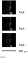
- Three-dimensional (3D) ToF-SIMS analysis allows the measurement of maps on an inner glass surface.
- the area resolution of 3D ToF-SIMS analyses has been estimated to around 4 x 4 ⁇ m, i.e. 16 ⁇ m 2 (cf. Figure 2 ).
- the first vicinity is characterised by a ToF-SIMS signal, wherein an area, having a ratio of an integrated Na 2 F + signal to an integrated 30 Si + signal of at least 0.10, wherein the Na 2 F + signal and the 30 Si + signal are integrated over a depth of 100 nm, is 36 mm 2 or less, 25 mm 2 or less, 20 mm 2 or less, 16 mm 2 or less, 10 mm 2 or less, 5 mm 2 or less, 3 mm 2 or less, or 1 mm 2 or less.
- the glass tube may only display small areas of deposited material above a detection threshold of an integrated Na 2 F + signal to an integrated 30 Si + signal of at least 0.10.
- the first vicinity is characterised by a ToF-SIMS signal, wherein an area, having a ratio of an integrated Na 2 F + signal to an integrated 30 Si + signal of at least 0.10 and not more than 0.50, wherein the Na 2 F + signal and the 30 Si + signal are integrated over a depth of 100 nm, is 36 mm 2 or less, 25 mm 2 or less, 20 mm 2 or less, 16 mm 2 or less 10 mm 2 or less, 5 mm 2 or less, 3 mm 2 or less, or 1 mm 2 or less.
- a ToF-SIMS signal wherein an area, having a ratio of an integrated Na 2 F + signal to an integrated 30 Si + signal of at least 0.10 and not more than 0.50, wherein the Na 2 F + signal and the 30 Si + signal are integrated over a depth of 100 nm, is 36 mm 2 or less, 25 mm 2 or less, 20 mm 2 or less, 16 mm 2 or less 10 mm 2 or less, 5 mm 2 or less, 3 mm
- the first vicinity is characterised by a ToF-SIMS signal, wherein an area, having a ratio of an integrated Na 2 F + signal to an integrated 30 Si + signal of at least 0.10 and not more than 0.50, wherein the Na 2 F + signal and the 30 Si + signal are integrated over a depth of 100 nm, is between 36 mm 2 and 0.0001 mm 2 , between 10 mm 2 and 0.001 mm 2 , between 3 mm 2 and 0.01 mm 2 , or between 1 mm 2 and 0.1 mm 2 .
- the first vicinity is characterised by a ToF-SIMS signal, wherein an area, having a ratio of an integrated Na 2 F + signal to an integrated 30 Si + signal of at least 0.10, wherein the Na 2 F + signal and the 30 Si + signal are integrated over a depth of 100 nm, is 0 mm 2 .
- the first vicinity is characterised by a ToF-SIMS signal, wherein an area, having a ratio of an integrated Na 2 F + signal to an integrated 30 Si + signal of at least 0.10 and not more than 0.50, wherein the Na 2 F + signal and the 30 Si + signal are integrated over a depth of 100 nm, is 0 mm 2 .
- the glass tube may be fully devoid of deposited material above a detection threshold of an integrated Na 2 F + signal to an integrated 30 Si + signal of at least 0.10.
- the ToF-SIMS signal is generated using Ga + at 25 keV as a primary ion source and at a primary ion current of 1pA, preferably at a mass resolution ⁇ m/m at a mass 65 of >5000, an analysis area of 50 x 50 ⁇ m 2 , using O 2 + at 1 keV as a sputter ion at a sputter ion current of 300 nA and a sputter area of 300 x 300 ⁇ m 2 , optionally using an electron floodgun for charge compensation.
- the ToF-SIMS signal is determined by normalising the counts of the detected ion species, such as e.g. Na 2 F + , to the counts of 30 Si + ions which are, by definition, set to 1, determining the sputter depth by measurement of the crater depth using white-light microscopy, and calculating the quotient between the integrated intensities of Na 2 F + and 30 Si + within the outer 100 nm of the inner surface.
- the quotient between the integrated intensities of Na 2 F + and 30 Si + within the outer 100 nm of the inner surface may be expressed as ⁇ Na 2 F + / ⁇ 30 Si + .
- the invention in a second aspect, relates to a glass tube for pharmaceutical containers, the glass tube having an inner surface and an outer surface, the glass tube having an inner diameter d i and an outer diameter d o , the glass tube having a first end and a second end, the glass tube having a first location, wherein the first location is at a distance of 400 mm from the first end, the glass tube having a first intermediate location, wherein the first intermediate location is at a distance of 15 mm from the first end, wherein the first end is formed into a first closed end, wherein preferably also the second end is formed into a second closed end, wherein a ventilation hole is located within a first vicinity of the first closed end, wherein the first vicinity is between the first intermediate location and the first location, the glass tube having a length l a along its longitudinal axis, the glass tube further having a middle section, wherein the middle section extends to a distance of 5 d i centred around the position of 0.5 l a along the longitudinal axis,
- the inventors have established that fluorescent components which are intentionally present in the glass composition, such as e.g. Fe 2 O 3 , TiO 2 , ZrO 2 , CeO 2 , As 2 O 3 , K 2 O, provide for fluorescence of the obtained glass tube.
- fluorescent components which are intentionally present in the glass composition, such as e.g. Fe 2 O 3 , TiO 2 , ZrO 2 , CeO 2 , As 2 O 3 , K 2 O
- One of these fluorescing oxide components for example ZrO 2
- the invention provides a glass tube for pharmaceutical containers with a ventilation hole, wherein deposited material on the inner glass surface of the glass tube is minimised and/or avoided compared to glass tubes known in the art, which allows high-throughput in-process screening via a fluorescence assay.
- An excitation light beam can be directed on the outer surface of a glass tube and will be refracted into the glass tube and totally internally reflected at the glass-air interface inside the glass tube.
- fluorescent components will be excited whose fluorescence can be detected orthogonally from the excitation beam.
- the inner surface of the glass tube has deposited material by e.g. components resulting from manufacturing, total internal reflection of the excitation light beam will be frustrated which leads to a loss of excitation light at the glass-air interface and/or a reduction excitation light intensity.
- This loss in excitation light (intensity) directly correlates with a loss in fluorescence emission which is readily detectable by a fluorescence detector.
- a suitable fluorescence detector can be integrated into the manufacturing apparatus and serves as a direct way of integrated product control.
- fluorescence emission is measured at an excitation wavelength of 290 nm and at an emission wavelength of 370 nm, wherein the slit width for excitation is 10 nm, and wherein the slit width for emission is 10 nm, wherein optionally the integration is 100 ms, wherein the glass tube is positioned in such a way that an angle between an incident excitation light beam and a reflected excitation light beam is around 90°, wherein fluorescence emission is detected at an angle of around 90°.
- a glass tube for pharmaceutical containers having an inner surface and an outer surface, the glass tube having an inner diameter d i and an outer diameter d o , the glass tube having a first end and a second end, the glass tube having a first location, wherein the first location is at a distance of 400 mm from the first end, the glass tube having a first intermediate location, wherein the first intermediate location is at a distance of 15 mm from the first end, wherein the first end is formed into a first closed end, wherein preferably also the second end is formed into a second closed end, wherein a ventilation hole is located within a first vicinity of the first closed end, wherein the first vicinity is between the first first intermediate location and the first location, the glass tube having a length l a along its longitudinal axis, the glass tube further having a middle section, wherein the middle section extends to a distance of 5 d i centred around the position of 0.5 l a along the longitudinal axis, wherein the glass tube has
- the glass tube has a ratio between the fluorescence emission determined at the first vicinity and the fluorescence emission determined at the middle section of at least 0.6, at least 0.7, at least 0.8, at least 0.9, or at least 0.95. In one embodiment, the glass tube has a ratio between the fluorescence emission determined at the first vicinity and the fluorescence emission determined at the middle section of 1.0 or less, 0.99 or less, 0.98 or less, 0.97 or less, or 0.96 or less. In one embodiment, the glass tube has a ratio between the fluorescence emission determined at the first vicinity and the fluorescence emission determined at the middle section of 0.6 to 1.0, 0.7 to 0.99, 0.8 to 0.98, 0.9 to 0.97, or 0.95 to 0.96.
- the glass tube has an inner surface at the first vicinity which resembles the inner surface of the middle section.
- the glass tube may display similar surface properties in both the first vicinity and the middle section reflecting a reduction and/or complete elimination of deposited material which may be found on the inner surface at the first vicinity.
- the inner surface comprises a deposit located in the first vicinity, wherein the deposit has a deposit area extending parallel to the inner surface of the glass tube, wherein the deposit area is 0.01 mm 2 to 36 mm 2 , and wherein the deposit has a ratio of an integrated Na 2 F + signal to an integrated 30 Si + signal of 0.0002 to less than 0.10, wherein the Na 2 F + signal and the 30 Si + signal are integrated over a depth of 100 nm.
- the deposit located in the first vicinity of the inner surface extends parallel to the inner surface of the glass tube, having a deposit area of 0.01 mm 2 to 36 mm 2 , and is identifiable and/or detectable by a ratio of an integrated Na 2 F + signal to an integrated 30 Si + signal of 0.0002 to less than 0.10, wherein the Na 2 F + signal and the 30 Si + signal are integrated over a depth of 100 nm.
- a deposit results from condensates and/or sublimates, such as sodium salts, e.g. NaCI and/or NaF, and/or borates, e.g. sodium borate, which may emanate through evaporation from the glass during the introduction of ventilation holes into the glass tube.
- condensates and/or sublimates such as sodium salts, e.g. NaCI and/or NaF
- borates e.g. sodium borate
- the deposit area is 0.01 mm 2 to 1 mm 2 and the deposit comprises a ratio of an integrated Na 2 F + signal to an integrated 30 Si signal of 0.0002 to less than 0.025, or the deposit area is 0.01 mm 2 to 36 mm 2 and the deposit comprises a ratio of an integrated Na 2 F + signal to an integrated 30 Si signal of 0.0002 to less than 0.025.
- the deposit area is at least 0.01 mm 2 , at least 0.03 mm 2 , at least 0.1 mm 2 , at least 0.2 mm 2 , at least 0.3 mm 2 , or at least 0.5 mm 2 . In one embodiment, the deposit area is 36 mm 2 or less, 25 mm 2 or less, 20 mm 2 or less, 16 mm 2 or less, 10 mm 2 or less, 5 mm 2 or less, 3 mm 2 or less, or 1 mm 2 or less.
- the deposit area is between 36 mm 2 and 0.01 mm 2 , between 25 mm 2 and 0.03 mm 2 , between 20 mm 2 and 0.05 mm 2 , between 16 mm 2 and 0.07 mm 2 , between 10 mm 2 and 0.1 mm 2 , between 5 mm 2 and 0.2 mm 2 , between 3 mm 2 and 0.3 mm 2 , or between 1 mm 2 and 0.5 mm 2 .
- the deposit comprises a ratio of an integrated Na 2 F + signal to an integrated 30 Si signal of at least 0.0002, at least 0.0005, at least 0.001, at least 0.002, at least 0.005, or at least 0.01. In one embodiment, the deposit comprises a ratio of an integrated Na 2 F + signal to an integrated 30 Si signal of 0.2 or less, 0.1 or less, 0.08 or less, 0.06 or less, 0.05 or less, 0.04 or less, or 0.025 or less. In one embodiment, the deposit comprises a ratio of an integrated Na 2 F + signal to an integrated 30 Si signal of 0.0002 to 0.2, 0.0005 to 0.1, 0.001 to 0.08, 0.002 to 0.06, 0.005 to 0.04, or 0.01 to 0.025.
- the deposit area is 0.01 mm 2 to 1 mm 2 and the deposit comprises a ratio of an integrated Na 2 F + signal to an integrated 30 Si signal of 0.0002 to 0.2, 0.0005 to 0.1, 0.001 to 0.08, 0.002 to 0.06, 0.005 to 0.04, or 0.01 to 0.025.
- the deposit comprises a ratio of an integrated Na 2 F + signal to an integrated 30 Si signal of 0.0002 to less than 0.025, wherein the deposit area is between 36 mm 2 and 0.01 mm 2 , between 25 mm 2 and 0.03 mm 2 , between 20 mm 2 and 0.05 mm 2 , between 16 mm 2 and 0.07 mm 2 , between 10 mm 2 and 0.1 mm 2 , between 5 mm 2 and 0.2 mm 2 , between 3 mm 2 and 0.3 mm 2 , or between 1 mm 2 and 0.5 mm 2 .
- At least 90% of the inner surface of the first vicinity, at least 99%, at least 99.9%, or at least 99.99%, are characterised by a ratio of an integrated Na 2 F + signal to an integrated 30 Si signal of 0.0002 to less than 0.025, wherein the Na 2 F + signal and the 30 Si + signal are integrated over a depth of 100 nm.
- At least 99% of the inner surface of the first vicinity are characterised by a ratio of an integrated Na 2 F + signal to an integrated 30 Si signal of 0.0002 to 0.2, 0.0005 to 0.1, 0.001 to 0.08, 0.002 to 0.06, 0.005 to 0.04, or 0.01 to 0.025, wherein the Na 2 F + signal and the 30 Si + signal are integrated over a depth of 100 nm.
- At least 99.99% of the inner surface of the first vicinity are characterised by a ratio of an integrated Na 2 F + signal to an integrated 30 Si signal of 0.0002 to 0.2, 0.0005 to 0.1, 0.001 to 0.08, 0.002 to 0.06, 0.005 to 0.04, or 0.01 to 0.025, wherein the Na 2 F + signal and the 30 Si + signal are integrated over a depth of 100 nm.
- the glass tube has a "hydrolytic resistance" which is defined as the alkali leachability on the middle section of the inner surface, determined as Na 2 O equivalents in an eluate prepared according to ISO 4802-2:2010, wherein the hydrolytic resistance is less than 0.5 ⁇ g cm -2 , less than 0.4 ⁇ g cm -2 , less than 0.3 ⁇ g cm -2 , less than 0.2 ⁇ g cm -2 , or less than 0.1 ⁇ g cm -2 .
- the glass tube has a hydrolytic resistance of at least 0.01 ⁇ g cm -2 , at least 0.02 ⁇ g cm -2 , at least 0.03 ⁇ g cm -2 , at least 0.04 ⁇ g cm -2 , or at least 0.05 ⁇ g cm -2 .
- the glass tube has a hydrolytic resistance from 0.01 to 0.5 ⁇ g cm -2 , 0.02 to 0.4 ⁇ g cm -2 , 0.03 to 0.3 ⁇ g cm -2 , 0.04 to 0.2 ⁇ g cm -2 , or 0.05 to 0.1 ⁇ g cm -2 .
- the glass tube comprises a glass composition selected from the list of soda-lime glass, borosilicate glass, aluminosilicate glass, a glass comprising from 5 to 20 mol% B 2 O 3 , based on all oxides present in the glass composition.
- the glass composition may comprise, among others, oxide species which inherently display at least to some fluorescence upon excitation with UV light, i.e. in the range of 100 to 380 nm, e.g. Fe 2 O 3 , TiO 2 , ZrO 2 , CeO 2 , As 2 O 3 and/or K 2 O.
- oxide species which inherently display at least to some fluorescence upon excitation with UV light, i.e. in the range of 100 to 380 nm, e.g. Fe 2 O 3 , TiO 2 , ZrO 2 , CeO 2 , As 2 O 3 and/or K 2 O.
- the glass tube comprises a glass composition comprising 5 to 20 mol% B 2 O 3 and/or 2 to 10 mol% Na 2 O.
- the glass composition comprises 60 to 85 mol% SiO 2 , 5 to 20 mol% B 2 O 3 , 2 to 10 mol% Al 2 O 3 , 0 to 2 mol% Fe 2 O 3 , 2 to 10 mol% Na 2 O, 0 to 5 mol% K 2 O, 0 to 2 mol% BaO, 0 to 2 mol% CaO, and/or 0 to 10 mol% TiO 2 , based on all oxides present in the glass composition.
- the glass composition comprises at least 60 mol% SiO 2 , at least 62 mol% SiO 2 , at least 64 mol% SiO 2 , at least 66 mol% SiO 2 , or at least 68 mol% SiO 2 , based on all oxides present in the glass composition. In one embodiment, the glass composition comprises 85 mol% SiO 2 or less, 83 mol% SiO 2 or less, 81 mol% SiO 2 or less, 79 mol% SiO 2 or less, or 77 mol% SiO 2 or less, based on all oxides present in the glass composition.
- the glass composition comprises 60 to 85 mol% SiO 2 , 62 to 83 mol% SiO 2 , 64 to 81 mol% SiO 2 , 66 to 79 mol% SiO 2 , or 68 to 77 mol% SiO 2 , based on all oxides present in the glass composition.
- the glass composition comprises at least 5.0 mol% B 2 O 3 , at least 5.5 mol% B 2 O 3 , at least 6.0 mol% B 2 O 3 , at least 6.5 mol% B 2 O 3 , or at least 7.0 mol% B 2 O 3 , based on all oxides present in the glass composition.
- the glass composition comprises 20.0 mol% B 2 O 3 or less, 18.0 mol% B 2 O 3 or less, 16.0 mol% B 2 O 3 or less, 14.0 mol% B 2 O 3 or less, or 12.0 mol% B 2 O 3 or less, based on all oxides present in the glass composition.
- the glass composition comprises 5.0 to 20.0 mol% B 2 O 3 , 5.5 to 18.0 mol% B 2 O 3 , 6.0 to 16.0 mol% B 2 O 3 , 6.5 to 14.0 mol% B 2 O 3 , or 7.0 to 12.0 mol% B 2 O 3 , based on all oxides present in the glass composition.
- the glass composition comprises at least 2.0 mol% Al 2 O 3 , at least 3.0 mol% Al 2 O 3 , at least 4.0 mol% Al 2 O 3 , or at least 5.0 mol% Al 2 O 3 , based on all oxides present in the glass composition. In one embodiment, the glass composition comprises 10.0 mol% Al 2 O 3 or less, 9.0 mol% Al 2 O 3 or less, 8.0 mol% Al 2 O 3 or less, or 7.0 mol% Al 2 O 3 or less, based on all oxides present in the glass composition.
- the glass composition comprises 2.0 to 10.0 mol% Al 2 O 3 , 3.0 to 9.0 mol% Al 2 O 3 , 4.0 to 8.0 mol% Al 2 O 3 , or 5.0 to 7.0 mol% Al 2 O 3 , based on all oxides present in the glass composition.
- the glass composition comprises at least 0 mol% Fe 2 O 3 , at least 0.2 mol% Fe 2 O 3 , or at least 0.5 mol% Fe 2 O 3 , based on all oxides present in the glass composition. In one embodiment, the glass composition comprises 2.0 mol% Fe 2 O 3 or less, 1.5 mol% Fe 2 O 3 or less, or 1.2 mol% Fe 2 O 3 or less, based on all oxides present in the glass composition. In one embodiment, the glass composition comprises 0 to 2.0 mol% Fe 2 O 3 , 0.2 to 1.5 mol% Fe 2 O 3 , or 0.5 to 1.2 mol% Fe 2 O 3 , based on all oxides present in the glass composition.
- the glass composition comprises at least 2 mol% Na 2 O, at least 4 mol% Na 2 O, or at least 6 mol% Na 2 O, based on all oxides present in the glass composition. In one embodiment, the glass composition comprises 10 mol% Na 2 O or less, 9 mol% Na 2 O or less, or 8 mol% Na 2 O or less, based on all oxides present in the glass composition. In one embodiment, the glass composition comprises 2 to 10 mol% Na 2 O, 4 to 9 mol% Na 2 O, or 6 to 8 mol% Na 2 O, based on all oxides present in the glass composition.
- the glass composition comprises at least 0.0 mol% K 2 O, at least 0.2 mol% K 2 O, or at least 0.5 mol% K 2 O, based on all oxides present in the glass composition. In one embodiment, the glass composition comprises 5.0 mol% K 2 O or less, 3.5 mol% K 2 O or less, 2.5 mol% K 2 O or less, 2.0 mol% K 2 O or less, or 1.5 mol% K 2 O or less, based on all oxides present in the glass composition. In one embodiment, the glass composition comprises 0.0 to 5.0 mol% K 2 O, 0.2 to 3.5 mol% K 2 O, or 0.5 to 2.5 mol% K 2 O, based on all oxides present in the glass composition.
- the glass composition comprises at least 0.0 mol% BaO, at least 0.2 mol% BaO, or at least 0.5 mol% BaO, based on all oxides present in the glass composition. In one embodiment, the glass composition comprises 3.0 mol% BaO or less, 2.5 mol% BaO or less, or 2.0 mol% BaO or less, based on all oxides present in the glass composition. In one embodiment, the glass composition comprises 0.0 to 3.0 mol% BaO, 0.2 to 2.5 mol% BaO, or 0.5 to 2.0 mol% BaO, based on all oxides present in the glass composition.
- the glass composition comprises at least 0.0 mol% CaO, at least 0.2 mol% CaO, or at least 0.5 mol% CaO, based on all oxides present in the glass composition. In one embodiment, the glass composition comprises 3.0 mol% CaO or less, 2.5 mol% CaO or less, or 2.0 mol% CaO or less, based on all oxides present in the glass composition. In one embodiment, the glass composition comprises 0.0 to 3.0 mol% CaO, 0.2 to 2.5 mol% CaO, or 0.5 to 2.0 mol% CaO, based on all oxides present in the glass composition.
- the glass composition comprises at least 0.0 mol% TiO 2 , at least 1.0 mol% TiO 2 , at least 2.0 mol% TiO 2 , at least 3.0 mol% TiO 2 , or at least 4.0 mol% TiO 2 , based on all oxides present in the glass composition. In one embodiment, the glass composition comprises 10.0 mol% TiO 2 or less, 9.0 mol% TiO 2 or less, 8.0 mol% TiO 2 or less, 7.0 mol% TiO 2 or less, or 6.0 mol% TiO 2 or less, based on all oxides present in the glass composition.
- the glass composition comprises 0.0 to 10.0 mol% TiO 2 , 1.0 to 9.0 mol% TiO 2 , 2.0 to 8.0 mol% TiO 2 , 3.0 to 7.0 mol% TiO 2 , or 4.0 to 6.0 mol% TiO 2 , based on all oxides present in the glass composition.
- the glass tube comprises a glass composition, wherein the glass composition comprises one or more fining agents, e.g. a fining agent selected from the list of arsenic oxide, antimony oxide, tin oxide, cerium oxide, chlorides, sulfates and combinations thereof.
- a fining agent selected from the list of arsenic oxide, antimony oxide, tin oxide, cerium oxide, chlorides, sulfates and combinations thereof.
- a fining agent in the glass composition to allow for bubble formation and bubble escape from the glass melt during the production process of the glass tube for pharmaceutical containers.
- the glass composition comprises a fining agent selected from the list of arsenic oxide, antimony oxide, and tin oxide.
- the glass composition comprises a fining agent selected from the list of chlorides, sulfates and combinations thereof.
- the glass composition has a viscosity of 10 2 dPas at a temperature above 1580 °C.
- the glass tube has an inner diameter from 5.0 to 49.0 mm, preferably 9.0 to 26 mm, and/or an outer diameter from 6.0 to 50 mm, preferably 8.0 to 30 mm, and/or a glass wall thickness of 0.5 to 2.0 mm, preferably 0.6 to 1.5 mm, and/or a length from 1100 to 5000 mm, preferably 1500 to 2000 mm.
- the glass tube has an inner diameter from 5.0 to 49.0 mm, 6.0 to 45.0 mm, 7.0 to 40.0 mm, 8.0 to 35.0 mm, or 9.0 to 26 mm.
- the glass tube for pharmaceutical containers, has an outer diameter from 6.0 to 50 mm, 7.0 to 40 mm, or 8.0 to 30 mm.
- the glass tube has a glass wall thickness of 0.5 to 2.0 mm, 0.6 to 1.5 mm, 0.7 to 1.3 mm, or 0.8 to 1.2 mm.
- the glass tube has a length from 1100 to 5000 mm, 1200 to 3000 mm, or 1500 to 2000 mm.
- a set comprising at least 50 glass tubes, at least 100 glass tubes, or at least 200 glass tubes. In one embodiment a set is provided comprising 1000 glass tubes or less, 700 glass tubes or less, or 500 glass tubes or less.
- the invention relates to a process for the production of a glass tube for pharmaceutical containers comprising the steps of
- the inventors have thus established a process for the production of a glass tube for pharmaceutical containers which avoids the problems known in the art and thereby provides a glass tube which is devoid of or at least minimises deposited material which may be observed on the inner surface.
- the process according to the invention provides a glass tube for pharmaceutical containers in which one of the open ends is formed into a closed end and wherein a ventilation hole is introduced into the glass tube and ensures an improvement in the inner surface conditions by means of employing suction during at least part of the introduction step and/or directly after the introduction step. It has been observed that during the high temperatures needed for the introduction of a ventilation hole into the glass tube parts of the glass composition may evaporate and subsequently condense on the inner surface of the glass tube, foremost in the vicinity near the closed end. In rare and extreme cases even visible deposits, such as e.g. micron-sized water stains, have been observed.
- the process according to the invention thus provides an effective counter-measure against deterioration of glass tubes during their manufacture into glass vials, glass ampoules, glass cartridges or glass syringes, and concomitantly ensures high-quality glass tubes by withdrawing any unwanted chemicals, species as part of the process.
- the glass tube has an inner surface and an outer surface, an inner diameter d i and an outer diameter d o , a length l a along its longitudinal axis, a first end and a second end, a first location, wherein the first location is at a distance of 400 mm from the first end, the glass tube having a first intermediate location, wherein the first intermediate location is at a distance of 15 mm from the first end, wherein a first vicinity is defined as the inner surface of the glass tube between the first intermediate location and the first location, wherein the introduction of the ventilation hole into the glass tube is in the first vicinity of the glass tube.
- the placement or introduction of the ventilation hole in the first vicinity of the glass tube has a number of practical benefits in the final product.
- the part of the glass tube with the ventilation hole can be easily removed by cutting or burning without substantial loss of glass material.
- the introduction of the ventilation hole in or near the first vicinity is advantageous also from a machine design. That is to say, the machine part providing for suction does not need to be introduced very deeply into the glass tube.
- the employment of suction during the introduction step is accompanied by heating of the glass tube in the first vicinity of the glass tube to a temperature of at least 100 °C, at least 150 °C, or at least 200 °C. In one embodiment of the process, the employment of suction during the introduction step is accompanied by heating of the glass tube in the first vicinity of the glass tube to a temperature of 400 °C or less, 350 °C or less, or 300 °C or less. In one embodiment of the process, the employment of suction during the introduction step is accompanied by heating of the glass tube in the first vicinity of the glass tube to a temperature of 100 °C to 400 °C, 150 °C to 350 °C, or 200 °C to 300 °C.
- heating the glass tube in the first vicinity in combination with the employment of suction provides for an efficient removal of those species that tend to condensate and/or sublimate, such as sodium salts, e.g. NaCI and/or NaF, and/or borates, e.g. sodium borate, which may emanate through evaporation from the glass during the introduction of ventilation holes into the glass tube.
- species that tend to condensate and/or sublimate such as sodium salts, e.g. NaCI and/or NaF
- borates e.g. sodium borate
- the employment of suction under stationary conditions effects an average air flow rate of 5 to 50 m s -1 , preferably 15 to 25 m s -1 inside the glass tube.
- a suitable air flow rate may additionally benefit the efficient removal of those species that tend to condensate and/or sublimate, such as sodium salts, e.g. NaCI and/or NaF, and/or borates, e.g. sodium borate, which may emanate through evaporation from the glass during the introduction of ventilation holes into the glass tube.
- sodium salts e.g. NaCl and/or NaF
- borates e.g. sodium borate
- the introduction of the ventilation hole starts at time point t 0 and ends at time point t 2
- the employment of suction starts at time point t 1 and ends at time point t 3 , wherein t 1 is between to and t 2 , and wherein t 3 is after t 2 .
- the timing between the introduction of the ventilation hole and the employment of suction is optimised in such a way which allows and provides for an efficient removal of those species that tend to condensate and/or sublimate, such as sodium salts, e.g. NaCl and/or NaF, and/or borates, e.g. sodium borate, at a time window when they may typically emanate through evaporation from the glass during the process.
- those species that tend to condensate and/or sublimate such as sodium salts, e.g. NaCl and/or NaF
- borates e.g. sodium borate
- Samples were placed and measured in a 45° geometry, providing for a right angle between excitation and emission beam. Samples were placed in a sample chamber in such a way that the UV light beam enters the glass tube and is reflected inside the wall of the glass tube by way of total internal reflection. Upon passing through the glass wall, UV light excites fluorescent species present in the glass composition, such as Fe 2 O 3 , TiO 2 , ZrO 2 , CeO 2 , As 2 O 3 , K 2 O, whose emission is detected in a right angle with respect to the excitation beam. In case the glass tube shows deviations on the inner surface, such as e.g.
- the following spectrometer settings were employed: a lit width for excitation and emission of 10 nm, integration time for steady state measurements of 0.1 s, and a wavelength sampling of 1 nm.
- the samples were first subjected to an assessment under a 254 nm excitation lamp to visually judge the fluorescence and homogeneity, and to look for areas that appear inhomogeneous which were identified and prepared for the test. Fluorescence emission of six samples was determined to measure the glass-inherent fluorescence.
- the ToF-SIMS technique is based on the erosion of a surface by a sputter ion-beam.
- the secondary ions produced by the primary ion beam are extracted from the surface and detected by mass separation.
- the generated depth profiles provide information on the qualitative surface composition for different ion species.
- a TOF-SIMS IV (ION-TOF GmbH) instrument was employed, using Ga + at 25 keV as primary ion at a primary ion current of 1 pA, at a mass resolution ⁇ m/m at mass 65: >5000, an analysis area of 50 x 50 ⁇ m 2 , and using O 2 + at 1 keV as a sputter ion and at a sputter ion current of 300 nA, a sputter area of 300 x 300 ⁇ m 2 , and employing an electron floodgun for charge compensation.
- the sputter depth was determined by subsequent measurement of the crater depth using white-light microscopy.
- the quotient between integrated intensities of Na 2 F + and 30 Si + was calculated within the outer 100 nm layer of the surface, being ⁇ Na 2 F + / ⁇ 30 Si + .
- ToF-SIMS data were acquired and interpreted applying the standards ASTM E 1829 - 14 (2014; Standard Guide for Handling Specimens Prior to Surface Analysis) and ASTM E 2695 - 09 (2009; Standard Guide for Interpretation of Mass Spectral Data Acquired with Time-of-Flight Secondary Ion Mass Spectroscopy). Specifically, the samples were handled in a way to keep them clean and to avoid the introduction of contaminations. The sampled glass tubes were opened and cracked, glass splinters were removed by blowing air/N 2 before data acquisition.
- the hydrolytic resistance is defined as the alkali leachability on the middle section of the inner surface.
- the alkali leachability on the inner surface is determined as Na 2 O equivalents in an eluate prepared according to ISO 4802-2:2010. This measured parameter is then related to the inner surface that has been in contact with the eluate during the ISO 4802-2:2010 method.
- each segment representing the middle section, each segment having a length of at least 25 mm, while alternatively also lengths of 50 mm and 60 mm are possible.
- each glass tube segment is capped from one open end, by definition referred to as the bottom end, with a silicone rubber plug. After filling with test water, the glass tube segment is capped at the other open end with aluminium foil. Before their first use, the silicone rubber plugs are cleaned, and the lack of alkali leachability from the silicone rubber plugs is confirmed. After each use the silicone rubber plugs are cleaned.
- the filling volume with distilled water is determined according to point 7.2.1 or point 7.2.2 of ISO 4802-2:2010 depending on the inner (or bore) diameter of the glass tube segment, i.e. d i ⁇ 20 mm or d i > 20 mm, respectively.
Abstract
The invention relates to a glass tube for pharmaceutical containers and a process for the production of a glass tube.
Description
- The invention relates to a glass tube for pharmaceutical containers and a process for the production of a glass tube.
- Glass tubes for pharmaceutical containers are known and widely encountered in hospitals and doctor's offices. There are high and continuously increasing demands on these glass tubes in order to guarantee the quality and integrity of the pharmaceuticals they contain.
- Glass tubes for pharmaceutical containers are typically manufactured from a glass melt which is drawn into a glass tube. During subsequent steps the drawn glass tube is cut into portions which are further processed into e.g. glass vials, glass ampoules, glass cartridges or glass syringes. In some glass tubes a ventilation hole is introduced.
- In the art, several problems are known that affect the performance and suitability of the glass tubes for the purpose of being used for pharmaceutical containers.
- Glass tubes for pharmaceutical containers are a mass product. Despite their putative simplicity and low cost, high-quality demands are placed on them and need to be ensured during and after manufacture and are thus subject to quality control before sale. In particular, contaminations are not acceptable, as even miniscule amounts of contaminants may have inferior negative effect on the quality of pharmaceutical products.
- Glass tubes for pharmaceutical containers are made from glass compositions melting at high temperatures. The reason is that excellent hydrolytic resistance, i.e. one of the fundamental requirements of glass for pharmaceutical containers, is based on glass constituents with very high melting points, e.g. SiO2 and Al2O3. Hence, during production, high melting temperatures may be necessary to achieve melt viscosities sufficient for homogenization and removal of bubbles from the melt. However, high melting temperatures also put high demands on the material of the melting furnace and refining tank. For example, the dissolution of material from the melting and/or refining furnace into the glass melt should be avoided by all means.
- Current production processes already provide for good quality standards. Nevertheless, the rare occurrence of contaminants in glass tubes has been reported, so that their prevention remains a constant focus and issue of attention for manufacturers of pharmaceutical containers.
- There remains a need to provide for sufficient and constant product monitoring to ensure the desired high-quality demands. Accordingly, there is a related as well as an independent demand that allows for a low cost, high-throughput and in-process control of the quality of the manufactured glass tubes.
- The above objects are solved by the subject-matter of the claims and by the subject-matter described here below.
- In a first aspect, the invention relates to a glass tube for pharmaceutical containers, the glass tube having an inner surface and an outer surface, the glass tube having an inner diameter di and an outer diameter do, the glass tube having a first end and a second end, the glass tube having a first location, wherein the first location is at a distance of 400 mm from the first end, the glass tube having a first intermediate location, wherein the first intermediate location is at a distance of 15 mm from the first end, wherein the first end is formed into a first closed end, wherein preferably also the second end is formed into a second closed end, wherein a ventilation hole is located within a first vicinity of the first closed end, wherein the first vicinity is between the first intermediate location and the first location, wherein ToF-SIMS signals are measurable on the inner surface in the first vicinity, including an Na2F+ signal and an 30Si+ signal, wherein an area on the inner surface in the first vicinity, having a ratio of an integrated Na2F+ signal to an integrated 30Si+ signal of at least 0.10, is 36 mm2 or less, wherein the Na2F+ signal and the 30Si+ signal are integrated over a depth of 100 nm.
- In a second and/or related aspect, the invention relates to a glass tube for pharmaceutical containers, the glass tube having an inner surface and an outer surface, the glass tube having an inner diameter di and an outer diameter do, the glass tube having a first end and a second end, the glass tube having a first location, wherein the first location is at a distance of 400 mm from the first end, the glass tube having a first intermediate location, wherein the first intermediate location is at a distance of 15 mm from the first end, wherein the first end is formed into a first closed end, wherein preferably also the second end is formed into a second closed end, wherein a ventilation hole is located within a first vicinity of the first closed end, wherein the first vicinity is between the first intermediate location and the first location, the glass tube having a length la along its longitudinal axis, the glass tube further having a middle section, wherein the middle section extends to a distance of 5 di centred around the position of 0.5 la along the longitudinal axis, wherein the glass tube has a ratio between the fluorescence emission determined at the first vicinity and the fluorescence emission determined at the middle section of at least 0.6.
- The invention thus provides a glass tube for pharmaceutical containers with a ventilation hole which allows high-throughput in-process screening via a fluorescence assay. The glass tubes of this disclosure have an improved fluorescence level as compared to conventional glass tubes. The inventors assume that this improved fluorescence level is due to a reduced level of deposited material on the inner surface of the first vicinity of the glass tube. It appears that the reduced level of contaminants increases the length of a travel path of light of an excitation wavelength within the glass tube wall because the portion of excitation light that is reflected at the inner surface of the glass tube is increased. This reflected portion of excitation light incident upon the glass tube via the outer surface enters the glass tube wall and is reflected at the inner surface so that the light passes through the glass tube wall twice and achieves stronger excitation of fluorescent species. It was found that a certain level of the contamination at the inner surface within the first vicinity appears to reduce the amount of light reflected at the inner surface, thereby reducing the emission of fluorescence from any fluorescent compounds of the glass tube. The glass tubes of this disclosure have reduced contamination at the inner surface of the first vicinity thereby increasing a fluorescence signal, or, phrased differently, reducing the negative impact of any contamination on fluorescence signal intensity. A stronger signal means that smaller amounts of fluorescent components can be detected in a fluorescence assay. It also means that a higher signal-to-noise ratio is achieved which allows for a higher reliability in a high-throughput assay. Thus, glass tubes of this invention allow high-throughput in-process screening via a fluorescence assay. The glass tubes of this invention show a residual fluorescence caused by fluorescent components intentionally present in the glass composition, such as e.g. Fe2O3, TiO2, ZrO2, CeO2, As2O3, K2O.
- ToF-SIMS (Time-of-Flight Secondary-Ion-Mass-Spectrometry) is a sensitive means to characterise glass surfaces and thereby lends itself to assess the inner surface of glass tubes. The inventors have established conditions and accordingly provided a glass tube for pharmaceutical containers with a ventilation hole, wherein deposited material resulting from manufacturing have been minimised compared to glass tubes known in the art. An integrated Na2F+ signal to an integrated 30Si+ signal serves as a fingerprint and/or an indication of deposited material on the inner glass surface which is characteristic of a glass tube for pharmaceutical containers. The glass tube according to the invention advantageously minimises the area in the vicinity of the first ventilation hole, where a characteristic signal can be detected, and hence for an increased fluorescence signal in the first vicinity.
- Fluorescent impurities from the glass melt, for example ZrO2 which may stem from the melting tank during the melting of a batch of glass raw materials, display fluorescence which can be detected in the obtained glass tube. The following phenomenon has been considered to explain why the minimisation of deposited material on the inner glass surface of the glass tube improves fluorescence detection: An excitation light beam can be directed on the outer surface of a glass tube and will be refracted into the glass and totally internally reflected at the glass-air interface towards the inner part of the glass tube. Along its light path inside the glass tube, (residual) fluorescent components will be excited whose fluorescence can be detected orthogonally from the excitation beam. In case the inner surface of the glass tube is affected by deposited material resulting from manufacturing, total internal reflection of the excitation light beam will be frustrated which leads to a loss of excitation light at the glass-air interface and/or a reduction excitation light intensity. This loss in excitation light (intensity) directly correlates with a loss in fluorescence emission which is readily detectable by a fluorescence detector. A suitable fluorescence detector can be integrated into the manufacturing apparatus and serves as a direct way of integrated product control. The absence of deposited material in the first vicinity can be confirmed by ToF-SIMS measurement and/or by comparing the residual fluorescence of the middle section of the glass tube with the residual fluorescence in the first vicinity. If the first vicinity displays deposited material originating from e.g. the introduction of the ventilation hole, fluorescence intensity will be low in the first vicinity compared to the middle section. The ToF-SIMS signal can be used to confirm absence of deposited material even in glass tubes without residual fluorescence.
- In a third aspect, the invention relates to a process for the production of a glass tube for pharmaceutical containers comprising the steps of
- providing a glass melt comprising volatile components, such as e.g. borates, preferably melting a batch of raw materials yielding the oxides comprised in the glass melt;
- forming the glass melt into a glass tube, e.g. by drawing;
- forming the glass tube into a glass tube with a first end and a second end;
- forming the first end into a first closed end;
- introducing a ventilation hole into the glass tube;
- employing suction during at least part of the introduction step and/or directly after the introduction step; and
- optionally forming and/or sealing the second end into a second closed end.
- The inventors have thus established a process for the production of a glass tube for pharmaceutical containers which allows high-throughput in-process screening via a fluorescence assay. The process according to the invention provides a glass tube for pharmaceutical containers in which one of the open ends is formed into a closed end and wherein a ventilation hole is introduced into the glass tube and ensures an improvement in the inner surface conditions by means of employing suction during at least part of the introduction step and/or directly after the introduction step. It has been observed that due to the high temperatures needed for the introduction of a ventilation hole into the glass tube, parts of the glass composition may evaporate and subsequently condense on the inner surface of the glass tube, foremost in the vicinity near the closed end. In rare and extreme cases even visible deposits, such as e.g. micron-sized water stains, have been observed. The process according to the invention thus provides an effective counter-measure against deposited material on the inner surface of glass tubes.
-
- Figure 1A
- shows a glass tube manufactured according to a process in the art displaying water stains on the inner surface.
- Figure 1B
- shows a glass tube manufactured according to a process in the art displaying borates deposited on the inner glass surface
- Figure 1C
- shows a glass tube manufactured according to a process of the invention.
- Figure 2
- shows three-dimensional ToF-SIMS mapping analyses acquired on affected inner surface regions of the glass tube shown in
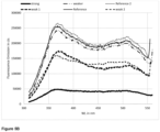
Figure 1A . The analysis is based on positive ion species detectable by ToF-SIMS. - Figure 3
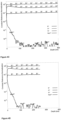
- shows an analysis of ToF-SIMS data obtained from five positions of an inner surface of a glass tube: The data relating to "Reference" and "
Reference 2" are devoid of deposited material; the data designated as "weaker" and "weak" display a signal originating from detectable stains; and the data denoted "strong" displays a signal originating from a severe stain. The monitored ToF-SIMS signal is based on a ratio of an integrated Na2F+ signal to an integrated 30Si+ signal, wherein the Na2F+ signal and the 30Si+ signal are integrated over a depth of 100 nm. - Figures 4A-E
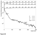
- shows the recording of the underlying ToF-SIMS data over a depth of more than 100 nm using the analysis and sputter parameters given in the Methods section. The recordings relate to the data shown in
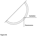
Figure 3 , whereinFigure 4A relates to "Reference 2",Figure 4B to "Reference",Figure 4C to "weaker",Figure 4D to "weak" andFigure 4E to the "strong" signal shown inFigure 3 . - Figure 5A
- shows the principle of the high-throughput fluorescence assay for monitoring the quality of the glass tubes. Excitation light from a xenon lamp was spectrally filtered by a monochromator and shone on a glass tube to allow penetration into the glass wall. Inside the glass wall, the excitation light beam is totally internally reflected. Fluorescence emission is collected in a right angle from the excitation light beam and spectrally filtered by a monochromator.
- Figure 5B
- shows the fluorescence spectra acquired from six positions of an inner surface of a glass tube.
Reference positions Figure 3 and4A to E and classified as 'weak 1', 'weak 2' and 'strong', display significantly reduced fluorescence emission. - In a first aspect, the invention relates to a glass tube for pharmaceutical containers, the glass tube having an inner surface and an outer surface, the glass tube having an inner diameter di and an outer diameter do, the glass tube having a first end and a second end, the glass tube having a first location, wherein the first location is at a distance of 400 mm from the first end, the glass tube having a first intermediate location, wherein the first intermediate location is at a distance of 15 mm from the first end, wherein the first end is formed into a first closed end, wherein preferably also the second end is formed into a second closed end, wherein a ventilation hole is located within a first vicinity of the first closed end, wherein the first vicinity is between the first intermediate location and the first location, wherein ToF-SIMS signals are measurable on the inner surface in the first vicinity, including an Na2F+ signal and an 30Si+ signal, wherein an area on the inner surface in the first vicinity, having a ratio of an integrated Na2F+ signal to an integrated 30Si+ signal of at least 0.10, is 36 mm2 or less, wherein the Na2F+ signal and the 30Si+ signal are integrated over a depth of 100 nm.
- ToF-SIMS (Time-of-Flight Secondary-Ion-Mass-Spectrometry) is a sensitive means to assess glass surfaces and thereby lends itself to assess the inner surface of glass tubes. The inventors have established conditions and accordingly provided a glass tube for pharmaceutical containers with a ventilation hole, wherein deposited material resulting from manufacturing has been minimised compared to glass tubes known in the art. An integrated Na2F+ signal to an integrated 30Si+ signal serves as a fingerprint and/or an indication of deposited material on the inner glass surface which is characteristic of a glass tube for pharmaceutical containers.
- To ensure a rigorous and thorough assessment of the inner surface of the glass tube, the Na2F+ signal was integrated over a depth of 100 nm and has been normalised to the 30Si signal in the same depth range. The 30Si isotope has been chosen to avoid detector saturation of the 28Si signal. Three-dimensional (3D) ToF-SIMS analysis allows the measurement of maps on an inner glass surface. The area resolution of 3D ToF-SIMS analyses has been estimated to around 4 x 4 µm, i.e. 16 µm2 (cf.
Figure 2 ). - In one embodiment of the glass tube, the first vicinity is characterised by a ToF-SIMS signal, wherein an area, having a ratio of an integrated Na2F+ signal to an integrated 30Si+ signal of at least 0.10, wherein the Na2F+ signal and the 30Si+ signal are integrated over a depth of 100 nm, is 36 mm2 or less, 25 mm2 or less, 20 mm2 or less, 16 mm2 or less, 10 mm2 or less, 5 mm2 or less, 3 mm2 or less, or 1 mm2 or less. Advantageously, the glass tube may only display small areas of deposited material above a detection threshold of an integrated Na2F+ signal to an integrated 30Si+ signal of at least 0.10.
- In one embodiment of the glass tube, the first vicinity is characterised by a ToF-SIMS signal, wherein an area, having a ratio of an integrated Na2F+ signal to an integrated 30Si+ signal of at least 0.10 and not more than 0.50, wherein the Na2F+ signal and the 30Si+ signal are integrated over a depth of 100 nm, is 36 mm2 or less, 25 mm2 or less, 20 mm2 or less, 16 mm2 or less 10 mm2 or less, 5 mm2 or less, 3 mm2 or less, or 1 mm2 or less. In one embodiment of the glass tube, the first vicinity is characterised by a ToF-SIMS signal, wherein an area, having a ratio of an integrated Na2F+ signal to an integrated 30Si+ signal of at least 0.10 and not more than 0.50, wherein the Na2F+ signal and the 30Si+ signal are integrated over a depth of 100 nm, is between 36 mm2 and 0.0001 mm2, between 10 mm2 and 0.001 mm2, between 3 mm2 and 0.01 mm2, or between 1 mm2 and 0.1 mm2.
- In one embodiment of the glass tube, the first vicinity is characterised by a ToF-SIMS signal, wherein an area, having a ratio of an integrated Na2F+ signal to an integrated 30Si+ signal of at least 0.10, wherein the Na2F+ signal and the 30Si+ signal are integrated over a depth of 100 nm, is 0 mm2. In one embodiment of the glass tube, the first vicinity is characterised by a ToF-SIMS signal, wherein an area, having a ratio of an integrated Na2F+ signal to an integrated 30Si+ signal of at least 0.10 and not more than 0.50, wherein the Na2F+ signal and the 30Si+ signal are integrated over a depth of 100 nm, is 0 mm2.
- Advantageously, the glass tube may be fully devoid of deposited material above a detection threshold of an integrated Na2F+ signal to an integrated 30Si+ signal of at least 0.10.
- In one embodiment, the ToF-SIMS signal is generated using Ga+ at 25 keV as a primary ion source and at a primary ion current of 1pA, preferably at a mass resolution Δm/m at a mass 65 of >5000, an analysis area of 50 x 50 µm2, using O2 + at 1 keV as a sputter ion at a sputter ion current of 300 nA and a sputter area of 300 x 300 µm2, optionally using an electron floodgun for charge compensation.
- In one embodiment, the ToF-SIMS signal is determined by normalising the counts of the detected ion species, such as e.g. Na2F+, to the counts of 30Si+ ions which are, by definition, set to 1, determining the sputter depth by measurement of the crater depth using white-light microscopy, and calculating the quotient between the integrated intensities of Na2F+ and 30Si+ within the outer 100 nm of the inner surface. The quotient between the integrated intensities of Na2F+ and 30Si+ within the outer 100 nm of the inner surface may be expressed as Σ Na2F+ / Σ 30Si+.
- In a second aspect, the invention relates to a glass tube for pharmaceutical containers, the glass tube having an inner surface and an outer surface, the glass tube having an inner diameter di and an outer diameter do, the glass tube having a first end and a second end, the glass tube having a first location, wherein the first location is at a distance of 400 mm from the first end, the glass tube having a first intermediate location, wherein the first intermediate location is at a distance of 15 mm from the first end, wherein the first end is formed into a first closed end, wherein preferably also the second end is formed into a second closed end, wherein a ventilation hole is located within a first vicinity of the first closed end, wherein the first vicinity is between the first intermediate location and the first location, the glass tube having a length la along its longitudinal axis, the glass tube further having a middle section, wherein the middle section extends to a distance of 5 di centred around the position of 0.5 la along the longitudinal axis, wherein the glass tube has a ratio between the fluorescence emission determined at the first vicinity and the fluorescence emission determined at the middle section of at least 0.6.
- The inventors have established that fluorescent components which are intentionally present in the glass composition, such as e.g. Fe2O3, TiO2, ZrO2, CeO2, As2O3, K2O, provide for fluorescence of the obtained glass tube. One of these fluorescing oxide components, for example ZrO2, may stem from the melting tank during the melting of a batch of glass raw materials. The invention provides a glass tube for pharmaceutical containers with a ventilation hole, wherein deposited material on the inner glass surface of the glass tube is minimised and/or avoided compared to glass tubes known in the art, which allows high-throughput in-process screening via a fluorescence assay.
- The following phenomenon has been found and has been turned into an industrial application: An excitation light beam can be directed on the outer surface of a glass tube and will be refracted into the glass tube and totally internally reflected at the glass-air interface inside the glass tube. Along its light path inside the glass tube, fluorescent components will be excited whose fluorescence can be detected orthogonally from the excitation beam. In case the inner surface of the glass tube has deposited material by e.g. components resulting from manufacturing, total internal reflection of the excitation light beam will be frustrated which leads to a loss of excitation light at the glass-air interface and/or a reduction excitation light intensity. This loss in excitation light (intensity) directly correlates with a loss in fluorescence emission which is readily detectable by a fluorescence detector. A suitable fluorescence detector can be integrated into the manufacturing apparatus and serves as a direct way of integrated product control.
- In one embodiment, fluorescence emission is measured at an excitation wavelength of 290 nm and at an emission wavelength of 370 nm, wherein the slit width for excitation is 10 nm, and wherein the slit width for emission is 10 nm, wherein optionally the integration is 100 ms, wherein the glass tube is positioned in such a way that an angle between an incident excitation light beam and a reflected excitation light beam is around 90°, wherein fluorescence emission is detected at an angle of around 90°.
- In one embodiment a glass tube for pharmaceutical containers is provided, the glass tube having an inner surface and an outer surface, the glass tube having an inner diameter di and an outer diameter do, the glass tube having a first end and a second end, the glass tube having a first location, wherein the first location is at a distance of 400 mm from the first end, the glass tube having a first intermediate location, wherein the first intermediate location is at a distance of 15 mm from the first end, wherein the first end is formed into a first closed end, wherein preferably also the second end is formed into a second closed end, wherein a ventilation hole is located within a first vicinity of the first closed end, wherein the first vicinity is between the first first intermediate location and the first location, the glass tube having a length la along its longitudinal axis, the glass tube further having a middle section, wherein the middle section extends to a distance of 5 di centred around the position of 0.5 la along the longitudinal axis, wherein the glass tube has a ratio between the fluorescence emission determined at the first vicinity and the fluorescence emission determined at the middle section of at least 0.6, wherein fluorescence emission is measured at an excitation wavelength of 290 nm and at an emission wavelength of 370 nm, wherein the slit width for excitation is 10 nm, and wherein the slit width for emission is 10 nm, wherein optionally the integration is 100 ms, wherein the glass tube is positioned in such a way that an angle between an incident excitation light beam and a reflected excitation light beam is around 90°, wherein fluorescence emission is detected at an angle of around 90°.
- In one embodiment, the glass tube has a ratio between the fluorescence emission determined at the first vicinity and the fluorescence emission determined at the middle section of at least 0.6, at least 0.7, at least 0.8, at least 0.9, or at least 0.95. In one embodiment, the glass tube has a ratio between the fluorescence emission determined at the first vicinity and the fluorescence emission determined at the middle section of 1.0 or less, 0.99 or less, 0.98 or less, 0.97 or less, or 0.96 or less. In one embodiment, the glass tube has a ratio between the fluorescence emission determined at the first vicinity and the fluorescence emission determined at the middle section of 0.6 to 1.0, 0.7 to 0.99, 0.8 to 0.98, 0.9 to 0.97, or 0.95 to 0.96.
- Advantageously, the glass tube has an inner surface at the first vicinity which resembles the inner surface of the middle section. In other words, the glass tube may display similar surface properties in both the first vicinity and the middle section reflecting a reduction and/or complete elimination of deposited material which may be found on the inner surface at the first vicinity.
- In one embodiment of the glass tube, the inner surface comprises a deposit located in the first vicinity, wherein the deposit has a deposit area extending parallel to the inner surface of the glass tube, wherein the deposit area is 0.01 mm2 to 36 mm2, and wherein the deposit has a ratio of an integrated Na2F+ signal to an integrated 30Si+ signal of 0.0002 to less than 0.10, wherein the Na2F+ signal and the 30Si+ signal are integrated over a depth of 100 nm.
- In one embodiment, the deposit located in the first vicinity of the inner surface extends parallel to the inner surface of the glass tube, having a deposit area of 0.01 mm2 to 36 mm2, and is identifiable and/or detectable by a ratio of an integrated Na2F+ signal to an integrated 30Si+ signal of 0.0002 to less than 0.10, wherein the Na2F+ signal and the 30Si+ signal are integrated over a depth of 100 nm.
- In one embodiment, a deposit results from condensates and/or sublimates, such as sodium salts, e.g. NaCI and/or NaF, and/or borates, e.g. sodium borate, which may emanate through evaporation from the glass during the introduction of ventilation holes into the glass tube.
- In one embodiment of the glass tube, the deposit area is 0.01 mm2 to 1 mm2 and the deposit comprises a ratio of an integrated Na2F+ signal to an integrated 30Si signal of 0.0002 to less than 0.025, or the deposit area is 0.01 mm2 to 36 mm2 and the deposit comprises a ratio of an integrated Na2F+ signal to an integrated 30Si signal of 0.0002 to less than 0.025.
- In one embodiment, the deposit area is at least 0.01 mm2, at least 0.03 mm2, at least 0.1 mm2, at least 0.2 mm2, at least 0.3 mm2, or at least 0.5 mm2. In one embodiment, the deposit area is 36 mm2 or less, 25 mm2 or less, 20 mm2 or less, 16 mm2 or less, 10 mm2 or less, 5 mm2 or less, 3 mm2 or less, or 1 mm2 or less. In one embodiment, the deposit area is between 36 mm2 and 0.01 mm2, between 25 mm2 and 0.03 mm2, between 20 mm2 and 0.05 mm2, between 16 mm2 and 0.07 mm2, between 10 mm2 and 0.1 mm2, between 5 mm2 and 0.2 mm2, between 3 mm2 and 0.3 mm2, or between 1 mm2 and 0.5 mm2.
- In one embodiment, the deposit comprises a ratio of an integrated Na2F+ signal to an integrated 30Si signal of at least 0.0002, at least 0.0005, at least 0.001, at least 0.002, at least 0.005, or at least 0.01. In one embodiment, the deposit comprises a ratio of an integrated Na2F+ signal to an integrated 30Si signal of 0.2 or less, 0.1 or less, 0.08 or less, 0.06 or less, 0.05 or less, 0.04 or less, or 0.025 or less. In one embodiment, the deposit comprises a ratio of an integrated Na2F+ signal to an integrated 30Si signal of 0.0002 to 0.2, 0.0005 to 0.1, 0.001 to 0.08, 0.002 to 0.06, 0.005 to 0.04, or 0.01 to 0.025.
- In one embodiment of the glass tube, the deposit area is 0.01 mm2 to 1 mm2 and the deposit comprises a ratio of an integrated Na2F+ signal to an integrated 30Si signal of 0.0002 to 0.2, 0.0005 to 0.1, 0.001 to 0.08, 0.002 to 0.06, 0.005 to 0.04, or 0.01 to 0.025.
- In one embodiment of the glass tube, the deposit comprises a ratio of an integrated Na2F+ signal to an integrated 30Si signal of 0.0002 to less than 0.025, wherein the deposit area is between 36 mm2 and 0.01 mm2, between 25 mm2 and 0.03 mm2, between 20 mm2 and 0.05 mm2, between 16 mm2 and 0.07 mm2, between 10 mm2 and 0.1 mm2, between 5 mm2 and 0.2 mm2, between 3 mm2 and 0.3 mm2, or between 1 mm2 and 0.5 mm2.
- In one embodiment of the glass tube, at least 90% of the inner surface of the first vicinity, at least 99%, at least 99.9%, or at least 99.99%, are characterised by a ratio of an integrated Na2F+ signal to an integrated 30Si signal of 0.0002 to less than 0.025, wherein the Na2F+ signal and the 30Si+ signal are integrated over a depth of 100 nm.
- In one embodiment of the glass tube, at least 99% of the inner surface of the first vicinity are characterised by a ratio of an integrated Na2F+ signal to an integrated 30Si signal of 0.0002 to 0.2, 0.0005 to 0.1, 0.001 to 0.08, 0.002 to 0.06, 0.005 to 0.04, or 0.01 to 0.025, wherein the Na2F+ signal and the 30Si+ signal are integrated over a depth of 100 nm.
- In one embodiment of the glass tube, at least 99.99% of the inner surface of the first vicinity are characterised by a ratio of an integrated Na2F+ signal to an integrated 30Si signal of 0.0002 to 0.2, 0.0005 to 0.1, 0.001 to 0.08, 0.002 to 0.06, 0.005 to 0.04, or 0.01 to 0.025, wherein the Na2F+ signal and the 30Si+ signal are integrated over a depth of 100 nm.
- In one embodiment, the glass tube has a "hydrolytic resistance" which is defined as the alkali leachability on the middle section of the inner surface, determined as Na2O equivalents in an eluate prepared according to ISO 4802-2:2010, wherein the hydrolytic resistance is less than 0.5 µg cm-2, less than 0.4 µg cm-2, less than 0.3 µg cm-2, less than 0.2 µg cm-2, or less than 0.1 µg cm-2.
- In one embodiment, the glass tube has a hydrolytic resistance of at least 0.01 µg cm-2, at least 0.02 µg cm-2, at least 0.03 µg cm-2, at least 0.04 µg cm-2, or at least 0.05 µg cm-2.
- In one embodiment, the glass tube has a hydrolytic resistance from 0.01 to 0.5 µg cm-2, 0.02 to 0.4 µg cm-2, 0.03 to 0.3 µg cm-2, 0.04 to 0.2 µg cm-2, or 0.05 to 0.1 µg cm-2.
- In one embodiment of the glass tube for pharmaceutical containers, the glass tube comprises a glass composition selected from the list of soda-lime glass, borosilicate glass, aluminosilicate glass, a glass comprising from 5 to 20 mol% B2O3, based on all oxides present in the glass composition.
- The glass composition may comprise, among others, oxide species which inherently display at least to some fluorescence upon excitation with UV light, i.e. in the range of 100 to 380 nm, e.g. Fe2O3, TiO2, ZrO2, CeO2, As2O3 and/or K2O.
- In one embodiment of the glass tube for pharmaceutical containers, the glass tube comprises a glass composition comprising 5 to 20 mol% B2O3 and/or 2 to 10 mol% Na2O. Optionally, the glass composition comprises 60 to 85 mol% SiO2, 5 to 20 mol% B2O3, 2 to 10 mol% Al2O3, 0 to 2 mol% Fe2O3, 2 to 10 mol% Na2O, 0 to 5 mol% K2O, 0 to 2 mol% BaO, 0 to 2 mol% CaO, and/or 0 to 10 mol% TiO2, based on all oxides present in the glass composition.
- In one embodiment, the glass composition comprises at least 60 mol% SiO2, at least 62 mol% SiO2, at least 64 mol% SiO2, at least 66 mol% SiO2, or at least 68 mol% SiO2, based on all oxides present in the glass composition. In one embodiment, the glass composition comprises 85 mol% SiO2 or less, 83 mol% SiO2 or less, 81 mol% SiO2 or less, 79 mol% SiO2 or less, or 77 mol% SiO2 or less, based on all oxides present in the glass composition. In one embodiment, the glass composition comprises 60 to 85 mol% SiO2, 62 to 83 mol% SiO2, 64 to 81 mol% SiO2, 66 to 79 mol% SiO2, or 68 to 77 mol% SiO2, based on all oxides present in the glass composition.
- In one embodiment, the glass composition comprises at least 5.0 mol% B2O3, at least 5.5 mol% B2O3, at least 6.0 mol% B2O3, at least 6.5 mol% B2O3, or at least 7.0 mol% B2O3, based on all oxides present in the glass composition. In one embodiment, the glass composition comprises 20.0 mol% B2O3 or less, 18.0 mol% B2O3 or less, 16.0 mol% B2O3 or less, 14.0 mol% B2O3 or less, or 12.0 mol% B2O3 or less, based on all oxides present in the glass composition. In one embodiment, the glass composition comprises 5.0 to 20.0 mol% B2O3, 5.5 to 18.0 mol% B2O3, 6.0 to 16.0 mol% B2O3, 6.5 to 14.0 mol% B2O3, or 7.0 to 12.0 mol% B2O3, based on all oxides present in the glass composition.
- In one embodiment, the glass composition comprises at least 2.0 mol% Al2O3, at least 3.0 mol% Al2O3, at least 4.0 mol% Al2O3, or at least 5.0 mol% Al2O3, based on all oxides present in the glass composition. In one embodiment, the glass composition comprises 10.0 mol% Al2O3 or less, 9.0 mol% Al2O3 or less, 8.0 mol% Al2O3 or less, or 7.0 mol% Al2O3 or less, based on all oxides present in the glass composition. In one embodiment, the glass composition comprises 2.0 to 10.0 mol% Al2O3, 3.0 to 9.0 mol% Al2O3, 4.0 to 8.0 mol% Al2O3, or 5.0 to 7.0 mol% Al2O3, based on all oxides present in the glass composition.
- In one embodiment, the glass composition comprises at least 0 mol% Fe2O3, at least 0.2 mol% Fe2O3, or at least 0.5 mol% Fe2O3, based on all oxides present in the glass composition. In one embodiment, the glass composition comprises 2.0 mol% Fe2O3 or less, 1.5 mol% Fe2O3 or less, or 1.2 mol% Fe2O3 or less, based on all oxides present in the glass composition. In one embodiment, the glass composition comprises 0 to 2.0 mol% Fe2O3, 0.2 to 1.5 mol% Fe2O3, or 0.5 to 1.2 mol% Fe2O3, based on all oxides present in the glass composition.
- In one embodiment, the glass composition comprises at least 2 mol% Na2O, at least 4 mol% Na2O, or at least 6 mol% Na2O, based on all oxides present in the glass composition. In one embodiment, the glass composition comprises 10 mol% Na2O or less, 9 mol% Na2O or less, or 8 mol% Na2O or less, based on all oxides present in the glass composition. In one embodiment, the glass composition comprises 2 to 10 mol% Na2O, 4 to 9 mol% Na2O, or 6 to 8 mol% Na2O, based on all oxides present in the glass composition.
- In one embodiment, the glass composition comprises at least 0.0 mol% K2O, at least 0.2 mol% K2O, or at least 0.5 mol% K2O, based on all oxides present in the glass composition. In one embodiment, the glass composition comprises 5.0 mol% K2O or less, 3.5 mol% K2O or less, 2.5 mol% K2O or less, 2.0 mol% K2O or less, or 1.5 mol% K2O or less, based on all oxides present in the glass composition. In one embodiment, the glass composition comprises 0.0 to 5.0 mol% K2O, 0.2 to 3.5 mol% K2O, or 0.5 to 2.5 mol% K2O, based on all oxides present in the glass composition.
- In one embodiment, the glass composition comprises at least 0.0 mol% BaO, at least 0.2 mol% BaO, or at least 0.5 mol% BaO, based on all oxides present in the glass composition. In one embodiment, the glass composition comprises 3.0 mol% BaO or less, 2.5 mol% BaO or less, or 2.0 mol% BaO or less, based on all oxides present in the glass composition. In one embodiment, the glass composition comprises 0.0 to 3.0 mol% BaO, 0.2 to 2.5 mol% BaO, or 0.5 to 2.0 mol% BaO, based on all oxides present in the glass composition.
- In one embodiment, the glass composition comprises at least 0.0 mol% CaO, at least 0.2 mol% CaO, or at least 0.5 mol% CaO, based on all oxides present in the glass composition. In one embodiment, the glass composition comprises 3.0 mol% CaO or less, 2.5 mol% CaO or less, or 2.0 mol% CaO or less, based on all oxides present in the glass composition. In one embodiment, the glass composition comprises 0.0 to 3.0 mol% CaO, 0.2 to 2.5 mol% CaO, or 0.5 to 2.0 mol% CaO, based on all oxides present in the glass composition.
- In one embodiment, the glass composition comprises at least 0.0 mol% TiO2, at least 1.0 mol% TiO2, at least 2.0 mol% TiO2, at least 3.0 mol% TiO2, or at least 4.0 mol% TiO2, based on all oxides present in the glass composition. In one embodiment, the glass composition comprises 10.0 mol% TiO2 or less, 9.0 mol% TiO2 or less, 8.0 mol% TiO2 or less, 7.0 mol% TiO2 or less, or 6.0 mol% TiO2 or less, based on all oxides present in the glass composition. In one embodiment, the glass composition comprises 0.0 to 10.0 mol% TiO2, 1.0 to 9.0 mol% TiO2, 2.0 to 8.0 mol% TiO2, 3.0 to 7.0 mol% TiO2, or 4.0 to 6.0 mol% TiO2, based on all oxides present in the glass composition.
- In one embodiment of the glass tube for pharmaceutical containers, the glass tube comprises a glass composition, wherein the glass composition comprises one or more fining agents, e.g. a fining agent selected from the list of arsenic oxide, antimony oxide, tin oxide, cerium oxide, chlorides, sulfates and combinations thereof.
- It is advantageous to use a fining agent in the glass composition to allow for bubble formation and bubble escape from the glass melt during the production process of the glass tube for pharmaceutical containers.
- In one embodiment of the glass tube for pharmaceutical containers, the glass composition comprises a fining agent selected from the list of arsenic oxide, antimony oxide, and tin oxide.
- In one embodiment of the glass tube for pharmaceutical containers, the glass composition comprises a fining agent selected from the list of chlorides, sulfates and combinations thereof.
- In one embodiment, the glass composition has a viscosity of 102 dPas at a temperature above 1580 °C.
- In one embodiment, the glass tube has an inner diameter from 5.0 to 49.0 mm, preferably 9.0 to 26 mm, and/or an outer diameter from 6.0 to 50 mm, preferably 8.0 to 30 mm, and/or a glass wall thickness of 0.5 to 2.0 mm, preferably 0.6 to 1.5 mm, and/or a length from 1100 to 5000 mm, preferably 1500 to 2000 mm.
- In one embodiment of the glass tube for pharmaceutical containers, the glass tube has an inner diameter from 5.0 to 49.0 mm, 6.0 to 45.0 mm, 7.0 to 40.0 mm, 8.0 to 35.0 mm, or 9.0 to 26 mm.
- In one embodiment of the glass tube for pharmaceutical containers, the glass tube has an outer diameter from 6.0 to 50 mm, 7.0 to 40 mm, or 8.0 to 30 mm.
- In one embodiment of the glass tube for pharmaceutical containers, the glass tube has a glass wall thickness of 0.5 to 2.0 mm, 0.6 to 1.5 mm, 0.7 to 1.3 mm, or 0.8 to 1.2 mm.
- In one embodiment of the glass tube for pharmaceutical containers, the glass tube has a length from 1100 to 5000 mm, 1200 to 3000 mm, or 1500 to 2000 mm.
- In one embodiment a set is provided comprising at least 50 glass tubes, at least 100 glass tubes, or at least 200 glass tubes. In one embodiment a set is provided comprising 1000 glass tubes or less, 700 glass tubes or less, or 500 glass tubes or less.
- In a third aspect, the invention relates to a process for the production of a glass tube for pharmaceutical containers comprising the steps of
- providing a glass melt comprising volatile components, such as e.g. borates, preferably melting a batch of raw materials yielding the oxides comprised in the glass melt;
- forming the glass melt into a glass tube, e.g. by drawing;
- forming the glass tube into a glass tube with a first end and a second end;
- forming the first end into a first closed end;
- introducing a ventilation hole into the glass tube;
- employing suction during at least part of the introduction step and/or directly after the introduction step; and
- optionally forming and/or sealing the second end into a second closed end.
- The inventors have thus established a process for the production of a glass tube for pharmaceutical containers which avoids the problems known in the art and thereby provides a glass tube which is devoid of or at least minimises deposited material which may be observed on the inner surface.
- The process according to the invention provides a glass tube for pharmaceutical containers in which one of the open ends is formed into a closed end and wherein a ventilation hole is introduced into the glass tube and ensures an improvement in the inner surface conditions by means of employing suction during at least part of the introduction step and/or directly after the introduction step. It has been observed that during the high temperatures needed for the introduction of a ventilation hole into the glass tube parts of the glass composition may evaporate and subsequently condense on the inner surface of the glass tube, foremost in the vicinity near the closed end. In rare and extreme cases even visible deposits, such as e.g. micron-sized water stains, have been observed. The process according to the invention thus provides an effective counter-measure against deterioration of glass tubes during their manufacture into glass vials, glass ampoules, glass cartridges or glass syringes, and concomitantly ensures high-quality glass tubes by withdrawing any unwanted chemicals, species as part of the process.
- In one embodiment of the process, the glass tube has an inner surface and an outer surface, an inner diameter di and an outer diameter do, a length la along its longitudinal axis, a first end and a second end, a first location, wherein the first location is at a distance of 400 mm from the first end, the glass tube having a first intermediate location, wherein the first intermediate location is at a distance of 15 mm from the first end, wherein a first vicinity is defined as the inner surface of the glass tube between the first intermediate location and the first location, wherein the introduction of the ventilation hole into the glass tube is in the first vicinity of the glass tube.
- The placement or introduction of the ventilation hole in the first vicinity of the glass tube has a number of practical benefits in the final product. For example, the part of the glass tube with the ventilation hole can be easily removed by cutting or burning without substantial loss of glass material. During the process for the production of a glass tube the introduction of the ventilation hole in or near the first vicinity is advantageous also from a machine design. That is to say, the machine part providing for suction does not need to be introduced very deeply into the glass tube.
- In one embodiment of the process, the employment of suction during the introduction step is accompanied by heating of the glass tube in the first vicinity of the glass tube to a temperature of at least 100 °C, at least 150 °C, or at least 200 °C. In one embodiment of the process, the employment of suction during the introduction step is accompanied by heating of the glass tube in the first vicinity of the glass tube to a temperature of 400 °C or less, 350 °C or less, or 300 °C or less. In one embodiment of the process, the employment of suction during the introduction step is accompanied by heating of the glass tube in the first vicinity of the glass tube to a temperature of 100 °C to 400 °C, 150 °C to 350 °C, or 200 °C to 300 °C.
- Advantageously, heating the glass tube in the first vicinity in combination with the employment of suction provides for an efficient removal of those species that tend to condensate and/or sublimate, such as sodium salts, e.g. NaCI and/or NaF, and/or borates, e.g. sodium borate, which may emanate through evaporation from the glass during the introduction of ventilation holes into the glass tube.
- In one embodiment of the process, the employment of suction under stationary conditions effects an average air flow rate of 5 to 50 m s-1, preferably 15 to 25 m s-1 inside the glass tube. Advantageously, a suitable air flow rate may additionally benefit the efficient removal of those species that tend to condensate and/or sublimate, such as sodium salts, e.g. NaCI and/or NaF, and/or borates, e.g. sodium borate, which may emanate through evaporation from the glass during the introduction of ventilation holes into the glass tube.
- The skilled artisan appreciates that sodium salts, e.g. NaCl and/or NaF, and/or borates, e.g. sodium borate, are typical components of glasses for pharmaceutical containers whose chemical properties bring about sublimation and/or condensation effects during the high temperatures employed for the production of glass tubes, in particular during the introduction of a ventilation hole.
- In one embodiment of the process, the introduction of the ventilation hole starts at time point t0 and ends at time point t2, and wherein the employment of suction starts at time point t1 and ends at time point t3, wherein t1 is between to and t2, and wherein t3 is after t2.
- Advantageously, the timing between the introduction of the ventilation hole and the employment of suction is optimised in such a way which allows and provides for an efficient removal of those species that tend to condensate and/or sublimate, such as sodium salts, e.g. NaCl and/or NaF, and/or borates, e.g. sodium borate, at a time window when they may typically emanate through evaporation from the glass during the process.
- A fluorescence spectrometer FLUOROLOG 3 of Horiba (PE-4-0503) was used.
- Samples were placed and measured in a 45° geometry, providing for a right angle between excitation and emission beam. Samples were placed in a sample chamber in such a way that the UV light beam enters the glass tube and is reflected inside the wall of the glass tube by way of total internal reflection. Upon passing through the glass wall, UV light excites fluorescent species present in the glass composition, such as Fe2O3, TiO2, ZrO2, CeO2, As2O3, K2O, whose emission is detected in a right angle with respect to the excitation beam. In case the glass tube shows deviations on the inner surface, such as e.g. deposits, physical changes affecting the surface roughness, or precipitation of volatile components (such as borates and halogenides), total internal reflection is frustrated which leads to an at least partial loss of excitation light. This loss in excitation light intensity effects a lower fluorescence emission, which thereby serves as a sensitive read-out for any deviations or inhomogeneities on the inner surface of the glass tube.
- The following spectrometer settings were employed: a lit width for excitation and emission of 10 nm, integration time for steady state measurements of 0.1 s, and a wavelength sampling of 1 nm. The measurement uncertainty (k=2) of the assay has been estimated to +/- 2.0% for the fluorescence intensity and +/- 1 nm for the wavelength.
- The samples were first subjected to an assessment under a 254 nm excitation lamp to visually judge the fluorescence and homogeneity, and to look for areas that appear inhomogeneous which were identified and prepared for the test. Fluorescence emission of six samples was determined to measure the glass-inherent fluorescence.
- An excitation wavelength of 290 nm was used which has proven to provide an efficient excitation for the glass compositions used as part of the invention (
Figure 5B ). Differences between the measured intensities between individual samples are larger than the relative measurement uncertainty of +/- 3% during the initial fluorescence measurements. - The ToF-SIMS technique is based on the erosion of a surface by a sputter ion-beam. The secondary ions produced by the primary ion beam are extracted from the surface and detected by mass separation. The generated depth profiles provide information on the qualitative surface composition for different ion species.
- A TOF-SIMS IV (ION-TOF GmbH) instrument was employed, using Ga+ at 25 keV as primary ion at a primary ion current of 1 pA, at a mass resolution Δm/m at mass 65: >5000, an analysis area of 50 x 50 µm2, and using O2 + at 1 keV as a sputter ion and at a sputter ion current of 300 nA, a sputter area of 300 x 300 µm2, and employing an electron floodgun for charge compensation.
- For the data evaluation all counts of ions were normalized to the 30Si+ ions which are, by definition, set to 1.
- The sputter depth was determined by subsequent measurement of the crater depth using white-light microscopy. The quotient between integrated intensities of Na2F+ and 30Si+ was calculated within the outer 100 nm layer of the surface, being Σ Na2F+ / Σ 30Si+.
- ToF-SIMS data were acquired and interpreted applying the standards ASTM E 1829 - 14 (2014; Standard Guide for Handling Specimens Prior to Surface Analysis) and ASTM E 2695 - 09 (2009; Standard Guide for Interpretation of Mass Spectral Data Acquired with Time-of-Flight Secondary Ion Mass Spectroscopy). Specifically, the samples were handled in a way to keep them clean and to avoid the introduction of contaminations. The sampled glass tubes were opened and cracked, glass splinters were removed by blowing air/N2 before data acquisition.
- The hydrolytic resistance is defined as the alkali leachability on the middle section of the inner surface. The alkali leachability on the inner surface is determined as Na2O equivalents in an eluate prepared according to ISO 4802-2:2010. This measured parameter is then related to the inner surface that has been in contact with the eluate during the ISO 4802-2:2010 method.
- To perform the test glass tubes are cut in respective segments, representing the middle section, each segment having a length of at least 25 mm, while alternatively also lengths of 50 mm and 60 mm are possible.
- Referring to point 8.3 of ISO 4802-2:2010, each glass tube segment is capped from one open end, by definition referred to as the bottom end, with a silicone rubber plug. After filling with test water, the glass tube segment is capped at the other open end with aluminium foil. Before their first use, the silicone rubber plugs are cleaned, and the lack of alkali leachability from the silicone rubber plugs is confirmed. After each use the silicone rubber plugs are cleaned. The filling volume with distilled water is determined according to point 7.2.1 or point 7.2.2 of ISO 4802-2:2010 depending on the inner (or bore) diameter of the glass tube segment, i.e. di ≤ 20 mm or di > 20 mm, respectively.
Claims (15)
- Glass tube for pharmaceutical containers, the glass tube having an inner surface and an outer surface, the glass tube having an inner diameter di and an outer diameter do, the glass tube having a first end and a second end, the glass tube having a first location, wherein the first location is at a distance of 400 mm from the first end, the glass tube having a first intermediate location, wherein the first intermediate location is at a distance of 15 mm from the first end,wherein the first end is formed into a first closed end, wherein preferably also the second end is formed into a second closed end,wherein a ventilation hole is located within a first vicinity of the first closed end, wherein the first vicinity is between the first intermediate location and the first location,wherein ToF-SIMS signals are measurable on the inner surface in the first vicinity, including an Na2F+ signal and an 30Si+ signal, wherein an area on the inner surface in the first vicinity, having a ratio of an integrated Na2F+ signal to an integrated 30Si+ signal of at least 0.10, is 36 mm2 or less, wherein the Na2F+ signal and the 30Si+ signal are integrated over a depth of 100 nm.
- Glass tube according to claim 1, wherein the area is 25 mm2 or less, 16 mm2 or less, 1 mm2 or less, and preferably 0 mm2.
- Glass tube for pharmaceutical containers, the glass tube having an inner surface and an outer surface, the glass tube having an inner diameter di and an outer diameter do, the glass tube having a first end and a second end, the glass tube having a first location, wherein the first location is at a distance of 400 mm from the first end, the glass tube having a first intermediate location, wherein the first intermediate location is at a distance of 15 mm from the first end,wherein the first end is formed into a first closed end, wherein preferably also the second end is formed into a second closed end,wherein a ventilation hole is located within a first vicinity of the first closed end, wherein the first vicinity is between the first intermediate location and the first location,the glass tube having a length la along its longitudinal axis, the glass tube further having a middle section, wherein the middle section extends to a distance of 5 di centred around the position of 0.5 la along the longitudinal axis,wherein the glass tube has a ratio between the fluorescence emission determined at the first vicinity and the fluorescence emission determined at the middle section of at least 0.6.
- Glass tube according to any one of the preceding claims, wherein the inner surface comprises a deposit located in the first vicinity, wherein the deposit has a deposit area extending parallel to the inner surface of the glass tube, wherein the deposit area is 0.01 mm2 to 36 mm2, and wherein the deposit has a ToF-SIMS signal measurable on the inner surface in the first vicinity, including an Na2F+ signal and an 30Si+ signal, having a ratio of an integrated Na2F+ signal to an integrated 30Si+ signal of 0.0002 to less than 0.10, wherein the Na2F+ signal and the 30Si+ signal are integrated over a depth of 100 nm.
- Glass tube according to claim 4, wherein the deposit area is 0.01 mm2 to 1 mm2 and wherein the deposit comprises a ratio of an integrated Na2F+ signal to an integrated 30Si signal of 0.0002 to less than 0.025, or wherein the deposit area is 0.01 mm2 to 36 mm2 and wherein the deposit comprises a ratio of an integrated Na2F+ signal to an integrated 30Si signal of 0.0002 to less than 0.025.
- Glass tube according to any one of the preceding claims, wherein at least 90% of the inner surface of the first vicinity, preferably at least 99%, are characterised by a ratio of an integrated Na2F+ signal to an integrated 30Si signal of 0.0002 to less than 0.025, wherein the Na2F+ signal and the 30Si+ signal are integrated over a depth of 100 nm.
- Glass tube according to any one of the preceding claims, the glass tube having a "hydrolytic resistance" which is defined as the alkali leachability on the middle section of the inner surface, determined as Na2O equivalents in an eluate prepared according to ISO 4802-2:2010, wherein the hydrolytic resistance is less than 0.5 µg cm-2, less than 0.4 µg cm-2, less than 0.3 µg cm-2, less than 0.2 µg cm-2, or less than 0.1 µg cm-2.
- Glass tube according to any one of the preceding claims, comprising a glass composition selected from the list of soda-lime glass, borosilicate glass, aluminosilicate glass, a glass comprising from 5 mol% to 20 mol% B2O3, based on all oxides present in the glass composition.
- Glass tube according to any one of the preceding claims, comprising a glass composition comprising 60 to 85 mol% SiO2, 5 to 20 mol% B2O3, 2 to 10 mol% Al2O3, 0 to 2 mol% Fe2O3, 2 to 10 mol% Na2O, 0 to 5 mol% K2O, 0 to 2 mol% BaO, 0 to 2 mol% CaO, 0 to 10 mol% TiO2, based on all oxides present in the glass composition.
- Glass tube according to any one of the preceding claims, wherein the glass tube has- an inner diameter di from 5.0 to 49.0 mm, preferably 9.0 to 26 mm, and/or- an outer diameter do from 6.0 to 50 mm, preferably 8.0 to 30 mm, and/or- a glass wall thickness WT of 0.5 to 2.0 mm, preferably 0.6 to 1.5 mm, and/or- a length la from 1100 to 5000 mm, preferably 1200 to 3000 mm, more preferably 1500 to 2000 mm.
- A set of glass tubes comprising at least 50 glass tubes according to any one of the preceding claims, preferably at least 100 glass tubes.
- Process for the production of a glass tube for pharmaceutical containers comprising the steps of- providing a glass melt comprising volatile components, such as e.g. borates, preferably melting a batch of raw materials yielding the oxides comprised in the glass melt;- forming the glass melt into a glass tube, e.g. by drawing;- forming the glass tube into a glass tube with a first end and a second end;- forming the first end into a first closed end;- introducing a ventilation hole into the glass tube;- employing suction during at least part of the introduction step and/or directly after the introduction step; and- optionally forming and/or sealing the second end into a second closed end.
- Process according to claim 12, the glass tube having an inner surface and an outer surface, the glass tube having an inner diameter di and an outer diameter do, the glass tube having a length la along its longitudinal axis, the glass tube having a first end and a second end, the glass tube having a first location, wherein the first location is at a distance of 400 mm from the first end, the glass tube having a first intermediate location, wherein the first intermediate location is at a distance of 15 mm from the first end, wherein a first vicinity is defined as the inner surface of the glass tube between the first intermediate location and the first location,
wherein the introduction of the ventilation hole into the glass tube is in the first vicinity of the glass tube. - Process according to claim 12 or claim 13, wherein the employment of suction during the introduction step is accompanied by heating of the glass tube in the first vicinity of the glass tube to a temperature of at least 100 °C.
- Process according to any one of claims 12 to 14, wherein the employment of suction under stationary conditions effects an average air flow rate of 5 to 50 m s-1, preferably 15 to 25 m s-1 inside the glass tube, and/orwherein the introduction of the ventilation hole starts at time point t0 and ends at time point t2, and wherein the employment of suction starts at time point t1 and ends at time point t3, wherein t1 is between t0 and t2, and wherein t3 is after t2, and/orcomprising the additional step of screening the glass tube, wherein the screening is performed by measuring fluorescence emission.
Priority Applications (4)
| Application Number | Priority Date | Filing Date | Title |
|---|---|---|---|
| EP21216969.2A EP4201896A1 (en) | 2021-12-22 | 2021-12-22 | Glass tube for pharmaceutical containers and process for the production of a glass tube |
| JP2022205214A JP2023093411A (en) | 2021-12-22 | 2022-12-22 | Glass tube for pharmaceutical container, and process for the production of glass tube |
| US18/145,817 US20230192350A1 (en) | 2021-12-22 | 2022-12-22 | Glass tube for pharmaceutical containers and process for the production of a glass tube |
| CN202211656456.4A CN116336264A (en) | 2021-12-22 | 2022-12-22 | Glass tube for a pharmaceutical container and method for producing a glass tube |
Applications Claiming Priority (1)
| Application Number | Priority Date | Filing Date | Title |
|---|---|---|---|
| EP21216969.2A EP4201896A1 (en) | 2021-12-22 | 2021-12-22 | Glass tube for pharmaceutical containers and process for the production of a glass tube |
Publications (1)
| Publication Number | Publication Date |
|---|---|
| EP4201896A1 true EP4201896A1 (en) | 2023-06-28 |
Family
ID=79025058
Family Applications (1)
| Application Number | Title | Priority Date | Filing Date |
|---|---|---|---|
| EP21216969.2A Pending EP4201896A1 (en) | 2021-12-22 | 2021-12-22 | Glass tube for pharmaceutical containers and process for the production of a glass tube |
Country Status (4)
| Country | Link |
|---|---|
| US (1) | US20230192350A1 (en) |
| EP (1) | EP4201896A1 (en) |
| JP (1) | JP2023093411A (en) |
| CN (1) | CN116336264A (en) |
Families Citing this family (13)
| Publication number | Priority date | Publication date | Assignee | Title |
|---|---|---|---|---|
| JP6500879B2 (en) * | 2016-08-30 | 2019-04-17 | 株式会社三洋物産 | Gaming machine |
| JP7235153B2 (en) * | 2017-12-29 | 2023-03-08 | 株式会社三洋物産 | game machine |
| JP7235154B2 (en) * | 2018-02-15 | 2023-03-08 | 株式会社三洋物産 | game machine |
| JP7231076B2 (en) * | 2018-03-08 | 2023-03-01 | 株式会社三洋物産 | game machine |
| JP2020130466A (en) * | 2019-02-15 | 2020-08-31 | 株式会社三洋物産 | Game machine |
| JP7234740B2 (en) * | 2019-03-28 | 2023-03-08 | 株式会社三洋物産 | game machine |
| JP7234741B2 (en) * | 2019-03-28 | 2023-03-08 | 株式会社三洋物産 | game machine |
| JP7234760B2 (en) * | 2019-04-11 | 2023-03-08 | 株式会社三洋物産 | game machine |
| JP7234761B2 (en) * | 2019-04-11 | 2023-03-08 | 株式会社三洋物産 | game machine |
| JP2023063369A (en) * | 2022-01-07 | 2023-05-09 | 株式会社三洋物産 | game machine |
| JP2023053387A (en) * | 2022-02-04 | 2023-04-12 | 株式会社三洋物産 | game machine |
| JP2023060270A (en) * | 2022-04-01 | 2023-04-27 | 株式会社三洋物産 | game machine |
| JP2023060269A (en) * | 2022-04-01 | 2023-04-27 | 株式会社三洋物産 | game machine |
Citations (4)
| Publication number | Priority date | Publication date | Assignee | Title |
|---|---|---|---|---|
| EP1369389A2 (en) * | 2002-06-05 | 2003-12-10 | Schott Glas | Tube preform and method for producing glass containers from a tube preform |
| DE10332176A1 (en) * | 2002-07-24 | 2004-02-12 | Schott Glas | Reducing alkali compound contamination on the inner surface of glass hollow bodies, e.g. containers used in medicine, during thermal treatment comprises creating an overpressure in the hollow body during thermal treatment |
| DE102011013623A1 (en) * | 2011-03-02 | 2012-09-06 | Schott Ag | Producing glass tube useful for producing ampoules and vials, comprises providing tubular semifinished product in form of tube length with two ends comprising first and second end, and pressing first end with molding tool |
| US20210284566A1 (en) * | 2016-08-16 | 2021-09-16 | Nippon Electric Glass Co., Ltd. | Glass tube production method |
-
2021
- 2021-12-22 EP EP21216969.2A patent/EP4201896A1/en active Pending
-
2022
- 2022-12-22 CN CN202211656456.4A patent/CN116336264A/en active Pending
- 2022-12-22 JP JP2022205214A patent/JP2023093411A/en active Pending
- 2022-12-22 US US18/145,817 patent/US20230192350A1/en active Pending
Patent Citations (4)
| Publication number | Priority date | Publication date | Assignee | Title |
|---|---|---|---|---|
| EP1369389A2 (en) * | 2002-06-05 | 2003-12-10 | Schott Glas | Tube preform and method for producing glass containers from a tube preform |
| DE10332176A1 (en) * | 2002-07-24 | 2004-02-12 | Schott Glas | Reducing alkali compound contamination on the inner surface of glass hollow bodies, e.g. containers used in medicine, during thermal treatment comprises creating an overpressure in the hollow body during thermal treatment |
| DE102011013623A1 (en) * | 2011-03-02 | 2012-09-06 | Schott Ag | Producing glass tube useful for producing ampoules and vials, comprises providing tubular semifinished product in form of tube length with two ends comprising first and second end, and pressing first end with molding tool |
| US20210284566A1 (en) * | 2016-08-16 | 2021-09-16 | Nippon Electric Glass Co., Ltd. | Glass tube production method |
Also Published As
| Publication number | Publication date |
|---|---|
| CN116336264A (en) | 2023-06-27 |
| JP2023093411A (en) | 2023-07-04 |
| US20230192350A1 (en) | 2023-06-22 |
Similar Documents
| Publication | Publication Date | Title |
|---|---|---|
| EP4201896A1 (en) | Glass tube for pharmaceutical containers and process for the production of a glass tube | |
| RU2674269C2 (en) | Delamination resistant glass containers | |
| Gratuze | Glass characterisation using laser ablation inductively coupled plasma mass spectrometry methods | |
| JP5047443B2 (en) | Borosilicate glass with high chemical resistance and use thereof | |
| Ryland | Sheet or container?—Forensic glass comparisons with an emphasis on source classification | |
| Ditter et al. | Impact of vial washing and depyrogenation on surface properties and delamination risk of glass vials | |
| US7521670B2 (en) | Standard for referencing luminescence signals | |
| Almirall | Elemental analysis of glass fragments | |
| Verhaar et al. | Development and validation of an analytical protocol for the sampling and quantitative analysis of ions on the surface of unstable historic glass in museum collections using ion-exchange chromatography | |
| Bottrell | Forensic glass comparison: background information used in data interpretation | |
| Scott et al. | In situ analysis of ancient glass: 17th century painted glass from Christ Church Cathedral, Oxford and Roman glass vessels | |
| Aerts et al. | Trace-level microanalysis of Roman glass from Khirbet Qumran, Israel | |
| Fearn et al. | Moisture attack on museum glass measured by SIMS | |
| Bange et al. | Characterization of defects in glasses and coatings on glasses by microanalytical techniques | |
| Pintori et al. | Insights on surface analysis techniques to study glass primary packaging | |
| Guadagnino et al. | Testing the glass material to predict delamination in pharmaceutical glass containers | |
| Müller et al. | Characterization and identification of local defects in glass | |
| EP3896039B1 (en) | Methods for determining chemical heterogeneity of glass containers | |
| EP4186874A1 (en) | Glass tube for pharmaceutical containers and process for the production of a glass tube | |
| Wilk et al. | Analysis of the elemental composition of glass fragments by LA-ICP-MS method. Part II: subsurface layers in container glass | |
| Winder et al. | Investigation of Liquid Contact Refractory Corrosion Under Oxy‐Fuel Glass Melting Atmospheres | |
| CODE | GUIDELINE FOR QUANTITATIVE ELEMENTAL ANALYSIS OF GLASS SAMPLES USING LA-ICP-MS | |
| Grainger | Categorisation and discrimination of automotive glass fragments by laser ablation inductively coupled plasma mass-spectrometry (LA-ICP-MS) for forensic purposes | |
| Eremin et al. | Conservation and analysis of deteriorating nineteenth and twentieth-century British glass in the National Museums of Scotland | |
| CN109738429A (en) | The rapid detection method of alkali is analysed in a kind of glaze spraying vial |
Legal Events
| Date | Code | Title | Description |
|---|---|---|---|
| STAA | Information on the status of an ep patent application or granted ep patent |
Free format text: STATUS: EXAMINATION IS IN PROGRESS |
|
| PUAI | Public reference made under article 153(3) epc to a published international application that has entered the european phase |
Free format text: ORIGINAL CODE: 0009012 |
|
| 17P | Request for examination filed |
Effective date: 20211222 |
|
| AK | Designated contracting states |
Kind code of ref document: A1 Designated state(s): AL AT BE BG CH CY CZ DE DK EE ES FI FR GB GR HR HU IE IS IT LI LT LU LV MC MK MT NL NO PL PT RO RS SE SI SK SM TR |
|
| RBV | Designated contracting states (corrected) |
Designated state(s): AL AT BE BG CH CY CZ DE DK EE ES FI FR GB GR HR HU IE IS IT LI LT LU LV MC MK MT NL NO PL PT RO RS SE SI SK SM TR |
|
| P01 | Opt-out of the competence of the unified patent court (upc) registered |
Effective date: 20230914 |