EP4201820A1 - Information processing system, method for setting release place, and program - Google Patents
Information processing system, method for setting release place, and program Download PDFInfo
- Publication number
- EP4201820A1 EP4201820A1 EP22211699.8A EP22211699A EP4201820A1 EP 4201820 A1 EP4201820 A1 EP 4201820A1 EP 22211699 A EP22211699 A EP 22211699A EP 4201820 A1 EP4201820 A1 EP 4201820A1
- Authority
- EP
- European Patent Office
- Prior art keywords
- release
- place
- sensing
- article
- information
- Prior art date
- Legal status (The legal status is an assumption and is not a legal conclusion. Google has not performed a legal analysis and makes no representation as to the accuracy of the status listed.)
- Granted
Links
Images






Classifications
-
- G—PHYSICS
- G05—CONTROLLING; REGULATING
- G05D—SYSTEMS FOR CONTROLLING OR REGULATING NON-ELECTRIC VARIABLES
- G05D1/00—Control of position, course, altitude or attitude of land, water, air or space vehicles, e.g. using automatic pilots
- G05D1/10—Simultaneous control of position or course in three dimensions
- G05D1/101—Simultaneous control of position or course in three dimensions specially adapted for aircraft
- G05D1/106—Change initiated in response to external conditions, e.g. avoidance of elevated terrain or of no-fly zones
-
- B—PERFORMING OPERATIONS; TRANSPORTING
- B64—AIRCRAFT; AVIATION; COSMONAUTICS
- B64C—AEROPLANES; HELICOPTERS
- B64C39/00—Aircraft not otherwise provided for
- B64C39/02—Aircraft not otherwise provided for characterised by special use
- B64C39/024—Aircraft not otherwise provided for characterised by special use of the remote controlled vehicle type, i.e. RPV
-
- B—PERFORMING OPERATIONS; TRANSPORTING
- B64—AIRCRAFT; AVIATION; COSMONAUTICS
- B64D—EQUIPMENT FOR FITTING IN OR TO AIRCRAFT; FLIGHT SUITS; PARACHUTES; ARRANGEMENT OR MOUNTING OF POWER PLANTS OR PROPULSION TRANSMISSIONS IN AIRCRAFT
- B64D1/00—Dropping, ejecting, releasing or receiving articles, liquids, or the like, in flight
- B64D1/02—Dropping, ejecting, or releasing articles
-
- B—PERFORMING OPERATIONS; TRANSPORTING
- B64—AIRCRAFT; AVIATION; COSMONAUTICS
- B64U—UNMANNED AERIAL VEHICLES [UAV]; EQUIPMENT THEREFOR
- B64U70/00—Launching, take-off or landing arrangements
-
- G—PHYSICS
- G05—CONTROLLING; REGULATING
- G05D—SYSTEMS FOR CONTROLLING OR REGULATING NON-ELECTRIC VARIABLES
- G05D1/00—Control of position, course, altitude or attitude of land, water, air or space vehicles, e.g. using automatic pilots
- G05D1/0011—Control of position, course, altitude or attitude of land, water, air or space vehicles, e.g. using automatic pilots associated with a remote control arrangement
- G05D1/0038—Control of position, course, altitude or attitude of land, water, air or space vehicles, e.g. using automatic pilots associated with a remote control arrangement by providing the operator with simple or augmented images from one or more cameras located onboard the vehicle, e.g. tele-operation
-
- G—PHYSICS
- G05—CONTROLLING; REGULATING
- G05D—SYSTEMS FOR CONTROLLING OR REGULATING NON-ELECTRIC VARIABLES
- G05D1/00—Control of position, course, altitude or attitude of land, water, air or space vehicles, e.g. using automatic pilots
- G05D1/04—Control of altitude or depth
- G05D1/06—Rate of change of altitude or depth
- G05D1/0607—Rate of change of altitude or depth specially adapted for aircraft
- G05D1/0653—Rate of change of altitude or depth specially adapted for aircraft during a phase of take-off or landing
- G05D1/0676—Rate of change of altitude or depth specially adapted for aircraft during a phase of take-off or landing specially adapted for landing
-
- B—PERFORMING OPERATIONS; TRANSPORTING
- B64—AIRCRAFT; AVIATION; COSMONAUTICS
- B64U—UNMANNED AERIAL VEHICLES [UAV]; EQUIPMENT THEREFOR
- B64U2101/00—UAVs specially adapted for particular uses or applications
- B64U2101/30—UAVs specially adapted for particular uses or applications for imaging, photography or videography
-
- B—PERFORMING OPERATIONS; TRANSPORTING
- B64—AIRCRAFT; AVIATION; COSMONAUTICS
- B64U—UNMANNED AERIAL VEHICLES [UAV]; EQUIPMENT THEREFOR
- B64U2101/00—UAVs specially adapted for particular uses or applications
- B64U2101/60—UAVs specially adapted for particular uses or applications for transporting passengers; for transporting goods other than weapons
- B64U2101/64—UAVs specially adapted for particular uses or applications for transporting passengers; for transporting goods other than weapons for parcel delivery or retrieval
-
- B—PERFORMING OPERATIONS; TRANSPORTING
- B64—AIRCRAFT; AVIATION; COSMONAUTICS
- B64U—UNMANNED AERIAL VEHICLES [UAV]; EQUIPMENT THEREFOR
- B64U2201/00—UAVs characterised by their flight controls
- B64U2201/20—Remote controls
Definitions
- the take-off and landing facility disclosed in Patent Literature 1 includes a fence that defines a take-off/landing place of the unmanned aerial vehicle, a sensor provided on the fence to detect a horizontal position and an altitude of the unmanned aerial vehicle, and a communication unit that transmits position information indicating the horizontal position and the altitude of the unmanned aerial vehicle to the unmanned aerial vehicle, thereby enabling the unmanned aerial vehicle to be appropriately landed.
- Patent Literature 1 WO 2021/210138 A
- one or more embodiments of the present invention are to providing an information processing system, a method for setting a release place, and a program that are capable of more efficiently setting a release place suitable for unmanned aerial vehicle to release an article.
- the information processing system may further include a first control unit configured to cause the unmanned aerial vehicle to start a flight toward the release place after the release place has been set. This makes it possible to set in advance a release place suitable for the unmanned aerial vehicle to release the article.
- the one or more application conditions may include that there is no obstacle in the release candidate place and that the release candidate place has a ground area of a predetermined size or more. This makes it possible to set a highly safe release place for the unmanned aerial vehicle to release the article.
- the information processing system may further include a processing unit configured to perform processing for issuing an alert at the release place in a case where it is determined that an obstacle enters the release place. This makes it possible to enhance safety prior to the release of the article from the unmanned aerial vehicle.
- the information processing system may further include a reception unit configured to receive a request to transport the article to the release place, the article being designated by the user. This makes it possible to promptly transport the article desired by the user to the release place.
- a third aspect of the invention is a program for causing a computer included in a terminal of a user on a ground to execute: acquiring, together with position information of the terminal, first sensing information obtained by sensing a peripheral area around the user including a release candidate place at which an article to be transported by an unmanned aerial vehicle is to be released, the sensing being performed by a sensor provided in the terminal and the release candidate place existing around the user; determining whether the release candidate place satisfies one or more predetermined application conditions as a place at which the article is able to be released on the basis of the first sensing information; and setting a release place suitable for releasing the article from the unmanned aerial vehicle on the basis of the release candidate place and the position information of the terminal in a case where it is determined that the release candidate place satisfies the one or more application conditions.
- the position information indicating the current position detected by the positioning unit 12 is output to the control unit 16. Furthermore, the positioning unit 12 may detect the current position (altitude) of the UAV 1 in the vertical direction by the altitude sensor such as an atmospheric pressure sensor. In this case, the position information includes altitude information indicating the altitude of the UAV 1.
- control unit 16 performs release control for releasing the article from the UAV 1 in a state in which the UAV 1 lands (landing state) in the release place or in a state in which the UAV 1 hovers (hovering state).
- the state of hovering in the release place refers to, for example, a state in which the UAV 1 is stopped at a position (in the air) separated from the ground or the rooftop surface of the building in the release place by several tens of centimeters to several meters in the vertical direction.
- the release candidate place exists around the user of the user terminal 2 (for example, a range of several meters to several tens of meters from the user).
- the peripheral area including the release candidate place means a release candidate place, and a peripheral area of the release candidate place.
- First sensing information obtained by sensing the peripheral area including the release candidate place existing around the user by the optical sensor 23 is output to the control unit 26.
- the terminal information acquisition unit 331 may acquire, from the user terminal 2 via the communication unit 31, the second sensing information obtained by sensing above the release candidate place with the optical sensor 23 provided in the user terminal 2. Furthermore, when the UAV 1 descends to release the article at the release place set by the release place setting unit 334, the terminal information acquisition unit 331 may acquire, from the user terminal 2 via the communication unit 31, the third sensing information obtained by sensing the peripheral area including the release place with the optical sensor 23 provided in the user terminal 2.
- the application condition determination unit 332 determines that the release candidate place does not satisfy the one or more application conditions. Moreover, even in a case where a ground area having a predetermined size or more is able to be extracted from the first sensing information, when an obstacle is detected in the ground area, the application condition determination unit 332 determines that the release candidate place does not satisfy the one or more application conditions.
- the release place setting unit 334 sets a release place suitable for releasing the article from the UAV 1 on the basis of the release candidate place, the position information of the user terminal 2, and the direction information. As a result, it is possible to set the release place more accurately.
- the UAV control unit 338 transmits a descent stop command to the UAV 1 via the communication unit 31 to cause the UAV 1 to stop the descent at the release place.
- step S16 the control unit 33 sets the release place by the release place setting unit 334 on the basis of the release candidate place and the position information of the user terminal 2 extracted in step S4.
- step S17 the control unit 33 transmits an article list related to the transportable article to the user terminal 2 via the communication unit 31 (step S17).
- the article list may indicate the article that has already been requested to be transported to the specific area including the release place.
- the control unit 26 of the user terminal 2 causes the operation/display unit 21 to display the article designation screen on which the article list is posted (step S18).
- control unit 26 of the user terminal 2 transmits the transport request of the article designated by the user to the management server 3 via the communication unit 24 as described above (step S19).
- the transport request includes the article ID and the quantity of the article designated by the user.
- the control unit 33 of the management server 3 selects the UAV 1 having the vehicle size smaller than the predetermined size indicated by the one or more application conditions determined in step S6 from among the UAVs 1 in the operable state as illustrated in FIG. 9 (step S20).
- the latest (newest) UAV 1 may be selected, or the UAV 1 having a low operation frequency may be selected.
- an appropriate UAV 1 may be selected according to at least one of the quantity, type, and size of the article indicated in the transport request.
- the control unit 33 of the management server 3 accesses the UAV 1 in accordance with the access information to the UAV 1 selected in step S20, and transmits a flight start command including the release place information indicating the planar size and position of the release place set in step S16 to the UAV 1 via the communication unit 31 by the UAV control unit 338 (step S22).
- the UAV 1 Upon receiving the flight start command, the UAV 1 takes off from the departure point and starts the flight of the UAV 1 toward the release place, and sequentially transmits the position information and the vehicle ID of the UAV 1 to the management server 3.
- step S24 the control unit 33 transmits, to the user terminal 2 via the communication unit 31, sensing instruction information for instructing to sense the peripheral area including the release place when the UAV 1 descends to release the article at the release place set in step S16.
- the control unit 26 of the user terminal 2 causes the operation/display unit 21 to display the guidance screen G3 for sensing the peripheral area including the release place (step S25).
- the release place frame 73 corresponding to the planar size of the release place set in step S16 is displayed on the guidance screen G3.
- a web page constituting the guidance screen G3 may be transmitted to the user terminal 2. In this case, the web page is displayed by the browser.
- step S28 determines whether an obstacle has entered or will enter the release place on the basis of the third sensing information. In a case where it is determined that the obstacle has entered or will enter the release place (step S28: YES), the processing proceeds to step S29. On the other hand, in a case where it is determined that no obstacle has entered or will enter the release place (step S28: NO), the processing proceeds to step S32.
- the management server 3 acquires the first sensing information obtained by sensing the peripheral area including the release candidate place existing around the user with the optical sensor 23 of the user terminal 2 and the position information of the user terminal 2, determines whether the release candidate place satisfies the one or more application conditions on the basis of the first sensing information, and in a case where it is determined that the release candidate place satisfies the one or more application conditions, sets the release place suitable for releasing the article from the UAV 1 on the basis of the release candidate place and the position information of the user terminal 2. Therefore, it is possible to more efficiently set the release place suitable for releasing the article by the UAV 1.
- the release place can be easily and accurately searched for as compared with the method of searching for the release place by using the UAV 1.
- the release place suitable for the UAV 1 to release the article is able to be set in advance before the UAV 1 takes off. Therefore, the search cost can be reduced as compared with the method of searching for the release place using the UAV 1.
- the user terminal 2 transmits release place information indicating the planar size and the position of the set release place to the management server 3 via the communication unit 24. Then, the management server 3 selects the UAV 1 on the basis of the release place information from the user terminal 2, and transmits a flight start command including the release place information to the selected UAV 1.
- the user terminal 2 may set the release place on the basis of the release candidate place, the position information of the user terminal 2, and the direction information indicating the direction of the optical sensor 23 at the time of sensing.
- the user terminal 2 may further determine, before the release place is set, whether there is an obstacle above the release candidate place on the basis of the second sensing information obtained by sensing above the release candidate place with the optical sensor 23, and in a case where it is determined that there is no obstacle above the release candidate place, may set the release place.
- the user terminal 2 may instruct the user to perform sensing above the release candidate place, and then acquire the second sensing information obtained by sensing above the release candidate place with the optical sensor 23.
Landscapes
- Engineering & Computer Science (AREA)
- Aviation & Aerospace Engineering (AREA)
- Radar, Positioning & Navigation (AREA)
- Remote Sensing (AREA)
- Physics & Mathematics (AREA)
- General Physics & Mathematics (AREA)
- Automation & Control Theory (AREA)
- Control Of Position, Course, Altitude, Or Attitude Of Moving Bodies (AREA)
- Traffic Control Systems (AREA)
Abstract
Description
- One or more embodiments of the present invention relates to a technical field such as a system that sets a place for releasing an article to be transported by an unmanned aerial vehicle on a ground.
- Conventionally, a technique related to a take-off/landing facility for appropriately landing an unmanned aerial vehicle is known. For example, the take-off and landing facility disclosed in
Patent Literature 1 includes a fence that defines a take-off/landing place of the unmanned aerial vehicle, a sensor provided on the fence to detect a horizontal position and an altitude of the unmanned aerial vehicle, and a communication unit that transmits position information indicating the horizontal position and the altitude of the unmanned aerial vehicle to the unmanned aerial vehicle, thereby enabling the unmanned aerial vehicle to be appropriately landed. - Patent Literature 1:
WO 2021/210138 A - However, for example, in a case where an unmanned aerial vehicle transports articles such as relief supplies to an evacuation area at the time of disaster, it is difficult to secure a place ensuring safety such as a take-off/landing facility on the ground in advance as a release place (for example, a place where the unmanned aerial vehicle lands) at which the unmanned aerial vehicle releases the articles. On the other hand, a method is also conceivable in which a predetermined information processing device selects a candidate area having a certain range from map information, causes an unmanned aerial vehicle to fly over the candidate area, and causes a sensor of the unmanned aerial vehicle to sense a lower side from the sky, thereby searching for a release place (for example, a place suitable for landing of an unmanned aerial vehicle) suitable for releasing the articles. However, in this case, since there may be a case where such a place does not exist in the candidate area, there is a possibility that the search using the unmanned aerial vehicle may be futile. Even if there is a release place suitable for releasing the articles from the unmanned aerial vehicle in the candidate area, there is a limit to a method in which the unmanned aerial vehicle performs sensing from the sky while flying at a predetermined speed, and there is a possibility that such a place may not be found.
- Therefore, one or more embodiments of the present invention are to providing an information processing system, a method for setting a release place, and a program that are capable of more efficiently setting a release place suitable for unmanned aerial vehicle to release an article.
- In response to the above issue, a first aspect of the invention is an information processing system including: an acquisition unit configured to acquire, together with position information of a terminal of a user on a ground, first sensing information obtained by sensing a peripheral area around the user including a release candidate place at which an article to be transported by an unmanned aerial vehicle is to be released, the sensing being performed by a sensor provided in the terminal; a first determination unit configured to determine whether the release candidate place satisfies one or more predetermined application conditions as a place at which the article is able to be released on the basis of the first sensing information; and a setting unit configured to set a release place suitable for releasing the article from the unmanned aerial vehicle on a basis of the release candidate place and the position information of the terminal, in a case where it is determined that the release candidate place satisfies the one or more application conditions. This makes it possible to more efficiently set a release place suitable for the unmanned aerial vehicle to release the article.
- The information processing system may further include a first control unit configured to cause the unmanned aerial vehicle to start a flight toward the release place after the release place has been set. This makes it possible to set in advance a release place suitable for the unmanned aerial vehicle to release the article.
- The one or more application conditions may include that there is no obstacle in the release candidate place and that the release candidate place has a ground area of a predetermined size or more. This makes it possible to set a highly safe release place for the unmanned aerial vehicle to release the article.
- The one or more application conditions may include that there is no obstacle in the release candidate place and that the release candidate place has a flat ground area of a predetermined size or more.
- The acquisition unit may be configured to acquire, before the release place is set and in response to an operation of the user, second sensing information obtained by the sensor sensing above the release candidate place, the first determination unit may be configured to determine whether there is an obstacle above the release candidate place on a basis of the second sensing information, and the setting unit may be configured to set the release place in a case where it is determined that there is no obstacle above the release candidate place. This makes it possible to set a release place with higher safety for the unmanned aerial vehicle to release the article.
- The information processing system may further include: an instruction unit configured to instruct the user to perform sensing above the release candidate place before the release place is set in a case where it is determined that the release candidate place satisfies the one or more application conditions, wherein the acquisition unit may be configured to acquire second sensing information obtained by sensing above the release candidate place with the sensor, in response to the operation of the user after the instruction is given to the user. This makes it possible to minimize the sensing above the release candidate place being wastefully performed.
- The acquisition unit may be configured to acquire third sensing information obtained by sensing a peripheral area including the release place with the sensor when the unmanned aerial vehicle descends to release the article at the release place, and the information processing system may further include a second determination unit configured to determine whether an obstacle has enterd or will enter the release place on the basis of the third sensing information. This makes it possible to more safely release the article from the unmanned aerial vehicle.
- The second determination unit may be configured to determine whether the obstacle has entered or will enter the release place by comparing images included in the first sensing information and the third sensing information. This makes it possible to accurately determine whether an obstacle enters the release place.
- The information processing system may further include a second control unit configured to cause the unmanned aerial vehicle to stop descent at the release place in a case where it is determined that the obstacle has entered or will enter the release place. This makes it possible to enhance safety prior to the release of the article from the unmanned aerial vehicle.
- The information processing system may further include a processing unit configured to perform processing for issuing an alert at the release place in a case where it is determined that an obstacle enters the release place. This makes it possible to enhance safety prior to the release of the article from the unmanned aerial vehicle.
- The information processing system may further include a reception unit configured to receive a request to transport the article to the release place, the article being designated by the user. This makes it possible to promptly transport the article desired by the user to the release place.
- The information processing system may further include a presentation unit configured to present to the user, before the user designates the article, information of an article that has already been requested to be transported to a specific area including the release place. This makes it possible to minimize the same article being requested to be transported to the same specific area.
- The acquisition unit may be configured to acquire direction information indicating a direction of the sensor at the time of the sensing, and the setting unit may be configured to set the release place on the basis of the release candidate place, position information of the terminal, and the direction information. This makes it possible to set the release place more accurately.
- A second aspect of the invention is a method for setting release place to be executed by one or more computers. The method includes: a step of acquiring, together with position information of a terminal of a user on a ground, first sensing information obtained by sensing a peripheral area around the user including a release candidate place at which an article to be transported by an unmanned aerial vehicle is to be released, the sensing being performed by a sensor provided in the terminal; a step of determining whether the release candidate place satisfies one or more predetermined application conditions as a place at which the article is able to be released on the basis of the first sensing information; and a step of setting a release place suitable for releasing the article from the unmanned aerial vehicle on the basis of the release candidate place and the position information of the terminal in a case where it is determined that the release candidate place satisfies the one or more application conditions.
- A third aspect of the invention is a program for causing a computer included in a terminal of a user on a ground to execute: acquiring, together with position information of the terminal, first sensing information obtained by sensing a peripheral area around the user including a release candidate place at which an article to be transported by an unmanned aerial vehicle is to be released, the sensing being performed by a sensor provided in the terminal and the release candidate place existing around the user; determining whether the release candidate place satisfies one or more predetermined application conditions as a place at which the article is able to be released on the basis of the first sensing information; and setting a release place suitable for releasing the article from the unmanned aerial vehicle on the basis of the release candidate place and the position information of the terminal in a case where it is determined that the release candidate place satisfies the one or more application conditions.
- According to one or more embodiments of the present invention, it is possible to more efficiently set a release place suitable for the unmanned aerial vehicle to release the article.
-
-
FIG. 1 is a diagram illustrating a schematic configuration example of an article transportation system S. -
FIG. 2 is a diagram illustrating a schematic configuration example of anUAV 1. -
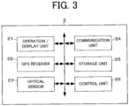
FIG. 3 is a diagram illustrating a schematic configuration example of auser terminal 2. -
FIG. 4 is a diagram illustrating an example of a guidance screen G1 for sensing a peripheral area including a release candidate place existing around a user. -
FIG. 5 is a diagram illustrating an example of a guidance screen G2 for sensing above the release candidate place. -
FIG. 6 is a diagram illustrating an example of a guidance screen G3 for sensing a peripheral area including a release place. -
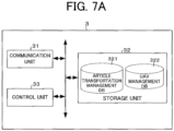
FIG. 7A is a diagram illustrating a schematic configuration example of amanagement server 3. -
FIG. 7B is a diagram illustrating an example of a functional block in acontrol unit 33. -
FIG. 8 is a sequence diagram illustrating an example of an operation of the article transportation system S when transportation of an article is performed. -
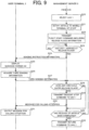
FIG. 9 is a sequence diagram illustrating an example of an operation of the article transportation system S when transportation of the article is performed. - Hereinafter, one or more embodiments of the present invention will be described with reference to the drawings. Incidentally, the following embodiment is an embodiment when the present invention is applied to an article transportation system.
- First, a configuration of an article transportation system S according to an embodiment of the present invention will be described with reference to
FIG 1. FIG. 1 is a diagram illustrating a schematic configuration example of the article transportation system S. As illustrated inFIG. 1 , the article transportation system S includes an unmanned aerial vehicle (hereinafter, referred to as "UAV (Unmanned Aerial Vehicle)") 1, auser terminal 2, and amanagement server 3, which are connectable to the communication network NW. Here, the article transportation system S is an example of an information processing system, and the UAV is an example of an unmanned flying body. The communication network NW includes, for example, the Internet, a mobile communication network, a radio base station thereof, and the like. - The
UAV 1 is also called a drone or a multi-copter, and is capable of flying from the ground according to remote control by an operator or autonomously flying in the air. TheUAV 1 is used to transport one or more articles (for example, rescue supplies and relief supplies) to a specific area having no take-off/landing facility (also referred to as take-off/landing port) prepared in advance for theUAV 1 to take off and land, such as an evacuation area at the time of disaster. Theuser terminal 2 is a terminal used by a user such as a person in need of rescue (disaster-stricken person) or a rescuer on the ground in a specific area. Incidentally, in the present embodiment, the user on the ground means a user who is (for example, standing) in contact with the ground or a rooftop surface of a building. Themanagement server 3 is used to search for a release place suitable for releasing the article from theUAV 1 in the specific area. - Next, the configuration and function of the
UAV 1 will be described with reference toFIG. 2. FIG. 2 is a diagram illustrating a schematic configuration example of theUAV 1. As illustrated inFIG. 2 , theUAV 1 includes adrive unit 11, apositioning unit 12, acommunication unit 13, asensor unit 14, astorage unit 15, acontrol unit 16, and the like. Furthermore, theUAV 1 includes a battery (not illustrated) that supplies power to each unit of theUAV 1, a rotor (propeller) that is a horizontal rotary wing, a holding mechanism for holding the article to be transported, and the like. The holding mechanism may be provided with a storage portion for storing the article.
In this case, an opening/closing door is provided on a side surface or a lower surface of the storage portion. Incidentally, the holding mechanism may include a wire and a reel (winch) for feeding or winding the wire. - The
drive unit 11 includes a motor, a rotation shaft, and the like. Thedrive unit 11 rotates a plurality of rotors by the motor, the rotation shaft, and the like that are driven in accordance with a control signal output from thecontrol unit 16. Thepositioning unit 12 includes a radio wave receiver, an altitude sensor, and the like. Thepositioning unit 12 receives, for example, a radio wave transmitted from a GNSS (global navigation satellite system) satellite by a radio receiver, and detects the current position (latitude and longitude) of theUAV 1 in the horizontal direction on the basis of the radio wave. The current position of theUAV 1 in the horizontal direction may be corrected on the basis of an image captured by a camera of thesensor unit 14. The position information indicating the current position detected by thepositioning unit 12 is output to thecontrol unit 16. Furthermore, thepositioning unit 12 may detect the current position (altitude) of theUAV 1 in the vertical direction by the altitude sensor such as an atmospheric pressure sensor. In this case, the position information includes altitude information indicating the altitude of theUAV 1. - The
communication unit 13 has a wireless communication function and is responsible for controlling communication performed via the communication network NW. Thesensor unit 14 includes various sensors used for flight control of theUAV 1. Examples of the various sensors include an optical sensor, a distance sensor, a triaxial angular velocity sensor, a triaxial acceleration sensor, and a geomagnetic sensor, and the like. The optical sensor includes, for example, a camera, and continuously senses (for example, images) a real space within a range that falls within an angle of view of the camera. Sensing information (for example, an image) obtained by sensing with thesensor unit 14 is output to thecontrol unit 16. Thestorage unit 15 includes a nonvolatile memory or the like, and stores various programs and data. Moreover, thestorage unit 15 stores a vehicle ID (identification information) for identifying theUAV 1. - The
control unit 16 includes at least one CPU (Central Processing Unit), a ROM (Read Only Memory), and a RAM (Random Access Memory), and executes various controls according to a program stored in the ROM (or the storage unit 15). For example, thecontrol unit 16 performs flight control to cause theUAV 1 to fly toward the release place set in the specific area. In this flight control, the rotation speed of the rotor, and the position, the attitude, and the traveling direction of theUAV 1 are controlled using the position information acquired from thepositioning unit 12, the sensing information acquired from thesensor unit 14, the release place information, and the like. As a result, theUAV 1 can autonomously move to the release place. The release place information indicates a planar size (width) and a position (latitude and longitude) of the release place. The release place information may be set at the departure point (flight start point) in theUAV 1, or may be set by being transmitted from themanagement server 3. Incidentally, during the flight of theUAV 1, the position information of theUAV 1 and the vehicle ID of theUAV 1 are sequentially transmitted to themanagement server 3 by thecommunication unit 13. - Moreover, the
control unit 16 performs release control for releasing the article from theUAV 1 in a state in which theUAV 1 lands (landing state) in the release place or in a state in which theUAV 1 hovers (hovering state). The state of hovering in the release place refers to, for example, a state in which theUAV 1 is stopped at a position (in the air) separated from the ground or the rooftop surface of the building in the release place by several tens of centimeters to several meters in the vertical direction. By the release control of thecontrol unit 16, the article is released by being separated from the holding mechanism of theUAV 1, or the article is released by opening the opening/closing door of the storage portion of the holding mechanism. Such release also includes a case where the article is taken out from the storage portion by the user. Incidentally, By feeding the wire by the reel of theUAV 1, the article may be released when the article or the storage portion thereof are lowered in the vertical direction and arrive on the ground or the rooftop surface of the building. - Next, the configuration and function of the
user terminal 2 will be described with reference toFIG. 3 .
FIG. 3 is a diagram illustrating a schematic configuration example of theuser terminal 2. Theuser terminal 2 includes an operation/display unit 21, a GPS (global positioning system)receiver 22, anoptical sensor 23, acommunication unit 24, astorage unit 25, acontrol unit 26, and the like. Incidentally, as theuser terminal 2, for example, a smartphone, a tablet, or the like can be applied. Theuser terminal 2 may include a voice processor and a speaker. The operation/display unit 21 has, for example, an input function of receiving an operation by a user's finger, a pen, or the like, and a display function of displaying various screens. TheGPS receiver 22 receives a radio wave transmitted from a GPS satellite, and detects the current position (latitude and longitude) of theuser terminal 2. The position information indicating the position detected by theGPS receiver 22 is output to thecontrol unit 26. - The
optical sensor 23 includes, for example, a camera, and senses (for example, images) a real space within a range that falls within an angle of view of the camera. Furthermore, theoptical sensor 23 includes a LiDAR (Light Detection and Ranging, or Laser Imaging Detection and Ranging) sensor. The LiDAR sensor can identify the distance and shape to an object by emitting laser light and measuring the time until the laser light is reflected by the object. Since such laser light has a high light flux density and a short wavelength, the shape of the object is able to be identified with high accuracy by the LiDAR sensor. In the present embodiment, theoptical sensor 23 is used to sense a peripheral area including a release candidate place that is a candidate for a release place. Here, the release candidate place exists around the user of the user terminal 2 (for example, a range of several meters to several tens of meters from the user). The peripheral area including the release candidate place means a release candidate place, and a peripheral area of the release candidate place. First sensing information obtained by sensing the peripheral area including the release candidate place existing around the user by theoptical sensor 23 is output to thecontrol unit 26. - Moreover, the
optical sensor 23 is also used to sense above (upper aerial area) the release candidate place in order to determine the presence or absence of an obstacle above the release candidate place. Second sensing information obtained by sensing above the release candidate place by theoptical sensor 23 is output to thecontrol unit 26. Furthermore, theoptical sensor 23 is also used to sense the peripheral area including the release place when theUAV 1 descends to release the article at the release place. Here, "when theUAV 1 descends" refers to immediately before theUAV 1 descends (that is, when theUAV 1 reaches the sky above the release place) or while theUAV 1 is descending. For example, the peripheral area including the release place means the release place, and a peripheral area of the release place. When theUAV 1 descends to release the article at the release place, third sensing information obtained by sensing the release place by theoptical sensor 23 is output to thecontrol unit 26. - The
communication unit 24 has a wireless communication function and is responsible for controlling communication performed via the communication network NW. Thestorage unit 25 includes a nonvolatile memory or the like, and stores various programs and data. The various programs include an operating system (OS), a release place setting application (including the program of the present invention), and a browser. The release place setting application is an application for causing theuser terminal 2 to sense a peripheral area including a release candidate place existing around the user and setting a release place. Incidentally, the release place setting application is downloaded from a predetermined server to theuser terminal 2. - The
control unit 26 includes at least one CPU, a ROM, a RAM, and the like, and executes processing according to a release place setting application stored in a ROM (or the storage unit 25). For example, thecontrol unit 26 causes the operation/display unit 21 to display a guidance screen G1 for sensing a peripheral area including a release candidate place existing around the user.FIG. 4 is a diagram illustrating an example of a guidance screen G1 for sensing a peripheral area including a release candidate place existing around the user. On the guidance screen G1 illustrated inFIG. 4 , a real-timereal space image 51 from theoptical sensor 23, aguidance message 52 of "PLEASE photograph RELEASE CANDIDATE PLACE OF ARTICLE", and adecision button 53 are displayed. In accordance with theguidance message 52, the user moves theuser terminal 2 so that the release candidate place determined to be appropriate by the user himself/herself falls within the guidance screen G1 (that is, the real space image 51), and performs an operation of designating (for example, tapping on the guidance screen G1) thedecision button 53. As a result, a sensing range of theoptical sensor 23 is set. - Then, in response to the user's operation, the
control unit 26 causes theoptical sensor 23 to sense the peripheral area including the release candidate place that falls within the guidance screen G1, for example, acquires the first sensing information obtained by the sensing, and acquires position information (that is, the position information of the user terminal 2) indicating a position detected by theGPS receiver 22 at the sensing timing. The first sensing information and the position information thus acquired are transmitted to themanagement server 3 by thecommunication unit 24. Then, in a case where themanagement server 3 determines that the release candidate place satisfies one or more application conditions (requirements) on the basis of the first sensing information, the release place is set on the basis of the release candidate place and the position information of theuser terminal 2. Incidentally, thecontrol unit 26 acquires direction information indicating the direction (orientation) of theoptical sensor 23 at the time of sensing. Here, the direction of theoptical sensor 23 is, for example, the optical axis direction of the camera or the emission direction of the LiDAR sensor, and is represented by an azimuth. In this case, the direction information is transmitted to themanagement server 3 together with the first sensing information and the position information, and the release place is set on the basis of the release candidate place, the position information, and the direction information. - Moreover, after acquiring the first sensing information, the
control unit 26 may cause the operation/display unit 21 to display a guidance screen G2 for sensing above the release candidate place.FIG. 5 is a diagram illustrating an example of the guidance screen G2 for sensing above the release candidate place. On the guidance screen G2 illustrated inFIG. 5 , a real-timereal space image 61 from theoptical sensor 23, aguidance message 62 of "PLEASE PHOTOGRAPH ABOVE RELEASE CANDIDATE PLACE OF ARTICLE", and adecision button 63 are displayed. In accordance with theguidance message 62, the user moves theuser terminal 2 so that the area above the release candidate place falls within the guidance screen G2 (that is, the real space image 61), and performs an operation of designating thedecision button 63. As a result, a sensing range of theoptical sensor 23 is set. Incidentally, after it is determined that the release candidate place satisfies the one or more application conditions, the guidance screen G2 is displayed according to the sensing instruction information transmitted from themanagement server 3 before the release place is set. Such sensing instruction information is information for instructing sensing above the release candidate place. - Then, in response to the user's operation, the
control unit 26 causes theoptical sensor 23 to sense above the release candidate place that falls within the guidance screen G2, for example, and acquires the second sensing information obtained by the sensing. The second sensing information thus acquired is transmitted to themanagement server 3 by thecommunication unit 24. Then, in a case where themanagement server 3 determines that the release candidate place satisfies the one or more application conditions, and determines that there is no obstacle above the release candidate place on the basis of the second sensing information, the release place is set. - When the release place existing around the user is set, it is possible to accept a transport request for an article that the user wants to be supplied. As a result, the article desired by the user are able to be promptly transported to the release place by the
UAV 1. For example, thecontrol unit 26 displays an article designation screen for designating the names, the quantity, and the like of the article on the operation/display unit 21, and transmits a transport request of the article designated by the user on the article designation screen to themanagement server 3 via thecommunication unit 24. Here, before the user designates the article, thecontrol unit 26 presents the article which have already been requested to be transported (for example, requested to be transported from auser terminal 2 of another user) to the specific area including the release place to the user. As a result, it is possible to minimize the same (that is, duplicated) article being requested to be transported to the same specific area. - Furthermore, after the release place has been set, when the
UAV 1 that transports the article arrives at the release place, thecontrol unit 26 may display a guidance screen G3 for sensing the peripheral area including the release place on the operation/display unit 21.FIG. 6 is a diagram illustrating an example of the guidance screen G3 for sensing the peripheral area including the release place. On the guidance screen G3 illustrated inFIG. 6 , a real-timereal space image 71 from theoptical sensor 23, aguidance message 72 of "ARTICLE HAS ARRIVED, PLEASE PHOTOGRAPH RELEASE PLACE OF ARTICLE", arelease place frame 73 corresponding to the planar size of the release place, and astart button 74 are displayed. In accordance with theguidance message 72, the user moves theuser terminal 2 so that the release candidate place determined to be appropriate by the user himself/herself substantially matches therelease place frame 73 displayed on the guidance screen G3 (that is, the real space image 71), and performs an operation of designating thestart button 74. As a result, the sensing range is set. - Then, in response to the user's operation, when the
UAV 1 descends to release the article at the release place, thecontrol unit 26 causes theoptical sensor 23 to continuously sense the peripheral area including the release place, and acquires the third sensing information obtained by the sensing. The third sensing information thus acquired is transmitted to themanagement server 3 by thecommunication unit 24. Then, in a case where themanagement server 3 determines that an obstacle has entered or will enters the release place on the basis of the third sensing information, thecontrol unit 26 performs an attention calling processing for calling attention (i.e. issuing an alert) to the user at the release place. In the attention calling processing, thecontrol unit 26 causes the operation/display unit 21 to display a message for calling attention to the user at the release place. Moreover, thecontrol unit 26 may cause a speaker to output, by voice, a message for calling attention to the user at the release place. - Next, the configuration and the function of the
management server 3 will be described with reference toFIGS. 7A and7B .FIG. 7A is a diagram illustrating a schematic configuration example of themanagement server 3. As illustrated inFIG. 7A , themanagement server 3 includes acommunication unit 31, astorage unit 32, acontrol unit 33, and the like. Thecommunication unit 31 is responsible for controlling communication performed via the communication network NW. The position information and the vehicle ID transmitted from theUAV 1 are received by thecommunication unit 31. Themanagement server 3 can recognize the current position of theUAV 1 from the position information of theUAV 1. Thestorage unit 32 includes, for example, a hard disk drive or the like, and stores various programs and data. Moreover, thestorage unit 32 stores an article list related to transportable article. The article list includes, for example, an article ID (identification information) of each article, a name, a type, a size, and a photographic image of the article. In thestorage unit 32, an articletransportation management database 321, aUAV management database 322, and the like are constructed. - The article
transportation management database 321 is a database for managing information related to transportation of the article. In the articletransportation management database 321, position information indicating the position of the specific area, the article ID, the name, the quantity, the type, the size, the photographic image, transport date, and the like of the article transported to the specific area are stored (registered) in association with each specific area. Here, the position information indicating the position of the specific area includes, for example, the position (latitude and longitude) of each point included in the specific area. - The
UAV management database 322 is a database for managing information related to theUAV 1. In theUAV management database 322, the vehicle ID of theUAV 1, the position information of theUAV 1, a vehicle size (body size) of theUAV 1, an operation (work) status of theUAV 1, access information to theUAV 1, and the like are stored (registered) in association with eachUAV 1. Here, the vehicle size is, for example, the planar size of the UAV 1 (length ym × width xm). The operation status indicates, for example, whether theUAV 1 is in an operable state for transportation of the article. For example, the operable state means a state in which the charging of the battery of theUAV 1 is completed and the flight can be started. The access information to theUAV 1 is information (for example, an IP address or the like) for thecenter server 3 to access theUAV 1. - The
control unit 33 includes at least one CPU, a ROM, a RAM, and the like.FIG. 7B is a diagram illustrating an example of a functional block in thecontrol unit 33. For example, according to a program (program code group) stored in the ROM or thestorage unit 32, as illustrated inFIG. 7B , thecontrol unit 33 functions as a terminal information acquisition unit 331 (an example of an acquisition unit), an application condition determination unit 332 (an example of a first determination unit), a sensing instruction unit 333 (an example of an instruction unit), a release place setting unit 334 (an example of a setting unit), an article presentation unit 335 (an example of a presentation unit), a transport request reception unit 336 (an example of a reception unit), an obstacle entry determination unit 337 (an example of a second determination unit), a UAV control unit 338 (an example of a first control unit and a second control unit), an attention calling processing unit 339 (an example of a processing unit), and the like. - The terminal
information acquisition unit 331 acquires, from theuser terminal 2 via thecommunication unit 31, the first sensing information obtained by sensing the peripheral area including the release candidate place existing around the user with theoptical sensor 23 provided in theuser terminal 2, and the position information of theuser terminal 2. At this time, the terminalinformation acquisition unit 331 may acquire direction information indicating the direction of theoptical sensor 23 at the time of sensing the first sensing information. - Moreover, before the release place is set by the release
place setting unit 334, the terminalinformation acquisition unit 331 may acquire, from theuser terminal 2 via thecommunication unit 31, the second sensing information obtained by sensing above the release candidate place with theoptical sensor 23 provided in theuser terminal 2. Furthermore, when theUAV 1 descends to release the article at the release place set by the releaseplace setting unit 334, the terminalinformation acquisition unit 331 may acquire, from theuser terminal 2 via thecommunication unit 31, the third sensing information obtained by sensing the peripheral area including the release place with theoptical sensor 23 provided in theuser terminal 2. - The application
condition determination unit 332 determines whether the release candidate place satisfies the one or more application conditions on the basis of the first sensing information acquired by the terminalinformation acquisition unit 331. Here, the one or more application conditions is one or more conditions determined in advance as a place at which the article is able to be released. For example, the application condition is a condition that there is no obstacle in the release candidate place and that the release candidate place includes a ground area of a predetermined size or more. As a result, it is possible to set a highly safe release place for theUAV 1 to release the article. The obstacle here is not particularly limited, but is rubble, trees, or the like that hinders landing of theUAV 1 or arrangement of the article. Moreover, the predetermined size is, for example, a planar size (length ym × width xm) with which theUAV 1 is able to safely release the article (for example, the size sufficient for theUAV 1 to safely land), and may be a fixed value or a variable value. Such a size is set, for example, on the basis of the vehicle size of theUAV 1 in the operable state in theUAV management database 322. Moreover, the ground area is an area on the ground or a rooftop surface of a building. - In a case where a ground area having a predetermined size or more is unable to be extracted from the first sensing information, the application
condition determination unit 332 determines that the release candidate place does not satisfy the one or more application conditions. Moreover, even in a case where a ground area having a predetermined size or more is able to be extracted from the first sensing information, when an obstacle is detected in the ground area, the applicationcondition determination unit 332 determines that the release candidate place does not satisfy the one or more application conditions. Moreover, in a case where the first sensing information is obtained by sensing the release candidate place with the LiDAR sensor of theuser terminal 2, because a shape including the unevenness in the release candidate place can be identified (recognized), an application condition is set that at least there is no obstacle and a flat ground area of a predetermined size or more is included. As a result, it is possible to set a release place with higher safely for theUAV 1 to release the article. - Here, the flat ground area means that there is no unevenness on the ground or the rooftop surface of the building, or even if there is unevenness, the unevenness is equal to or less than a threshold value. In this case, in a case where a flat ground area of a predetermined size or more is unable to be extracted from the first sensing information, the application
condition determination unit 332 determines that the release candidate place does not satisfy the one or more application conditions. Incidentally, the application condition may include a condition that the gradient of the ground area is equal to or less than a threshold value in addition to the above-described condition. - In a case where the application
condition determination unit 332 determines that the release candidate place satisfies the one or more application conditions, thesensing instruction unit 333 transmits sensing instruction information to theuser terminal 2 via thecommunication unit 31 to display the guidance screen G2 before the release place is set by the releaseplace setting unit 334, thereby instructing the user of theuser terminal 2 to perform sensing above the release candidate place. As a result, it is possible to minimize the sensing above the release candidate place being wastefully performed. - Then, in a case where the terminal
information acquisition unit 331 acquires the second sensing information after the user is instructed to perform sensing above the release candidate place (after the instruction is given to the user), the applicationcondition determination unit 332 further determines whether there is an obstacle above the release candidate place on the basis of the second sensing information. As a result, it is possible to set a release place with higher safely for theUAV 1 to release the article. The obstacle here is not particularly limited, but is a tree, an electric wire, or the like that hinders descent of theUAV 1. In a case where an obstacle is detected above the release candidate place from the second sensing information, the applicationcondition determination unit 332 determines that there is an obstacle above the release candidate place. - In a case where the application
condition determination unit 332 determines that the release candidate place satisfies the one or more application conditions, the releaseplace setting unit 334 sets a release place suitable for releasing the article from theUAV 1 on the basis of the release candidate place and the position information of theuser terminal 2. Here, setting the release place means, for example, setting the planar size and position (latitude and longitude) of the release place. For example, the planar size of the release place is set from among the ground areas having no obstacle and a predetermined size or more in the release candidate place indicated by the first sensing information. The planar size of the release place may match the planar size of the release candidate place. The position of the release place may be a current position indicated by the position information of theuser terminal 2. Since theUAV 1 descends while confirming safety and adjusting the position by sensing the lower side with thesensor unit 14, there is no particular problem even if the actual position of the release place slightly deviates from the position of the release place set by the releaseplace setting unit 334. - However, in a case where the terminal
information acquisition unit 331 acquires the position information and the like of theuser terminal 2 and the direction information indicating the direction of theoptical sensor 23 at the time of sensing the first sensing information, the releaseplace setting unit 334 sets a release place suitable for releasing the article from theUAV 1 on the basis of the release candidate place, the position information of theuser terminal 2, and the direction information. As a result, it is possible to set the release place more accurately. In this case, for example, the releaseplace setting unit 334 identifies (calculates) a distance from the current position (that is, the sensing position) indicated in the position information of theuser terminal 2 to the center position (position on the image) in the release place in the first sensing information (for example, an image), and sets the position (latitude and longitude) of the release place according to the distance and the direction (for example, azimuth) indicated in the direction information. - Moreover, in a case where the terminal
information acquisition unit 331 acquires the second sensing information, the releaseplace setting unit 334 sets the release place in a case where the applicationcondition determination unit 332 determines that the release candidate place satisfies the one or more application conditions and the applicationcondition determination unit 332 determines that there is no obstacle above the release candidate place. Incidentally, a condition that there is no obstacle above the release candidate place may be included in the application condition. In this case, the sensing instruction information is not required to be transmitted to theuser terminal 2 by thesensing instruction unit 333. - In a case where the release place has been set by the release
place setting unit 334, thearticle presentation unit 335 transmits the article list to theuser terminal 2 via thecommunication unit 31 and displays an article designation screen including the article list, thereby presenting the article (information of the article) that is able to be transported to the user of theuser terminal 2. At this time, thearticle presentation unit 335 may refer to the articletransportation management database 321 and indicate the article that has already been requested to be transported to the specific area including the set release place. That is, the article is indicated in the article list. As a result, the user of theuser terminal 2 can confirm the article that has already been requested to be transported to the specific area including the release place on the article designation screen. Then, the transportrequest reception unit 336 receives a transport request of the article designated by the user on the article designation screen (transport request to the release place) from theuser terminal 2 via thecommunication unit 31. The article related to the transport request thus received are loaded into theUAV 1 in the operable state. - In a case where the third sensing information is acquired by the terminal
information acquisition unit 331, the obstacleentry determination unit 337 determines whether an obstacle has entered or will enter the release place on the basis of the third sensing information. As a result, the article is able to be more safely released from theUAV 1. The obstacle here is not particularly limited, but is a moving person, animal, or the like that hinders release of the article by theUAV 1. Entry of an obstacle into the release place means that the obstacle is actually entering the release place, or that it is estimated that the obstacle will enter the release place from now on. In the latter case, for example, in a case where the obstacleentry determination unit 337 detects an obstacle moving toward the release place from the third sensing information, the obstacle enteringdetermination unit 337 determines that the obstacle will enter the release place. - Moreover, the obstacle
entry determination unit 337 determines whether an obstacle has entered or will enter the release place by comparing images included in the first sensing information and the third sensing information. As a result, it is possible to accurately determine whether an obstacle enters the release place. For example, in a case where an object detected in the image included in the third sensing information is unable to be detected in the image included in the first sensing information, the obstacleentry determination unit 337 recognizes the object as an obstacle, and determines whether the recognized obstacle has entered or will enter the release place. - The
UAV control unit 338 causes theUAV 1 to start the flight toward the release place set by the releaseplace setting unit 334. For example, theUAV control unit 338 transmits a flight start command including release place information indicating the planar size and position of the release place to theUAV 1 loaded with the article related to the transport request via thecommunication unit 31, thereby causing theUAV 1 to start the flight toward the release place. That is, after the release place has been set by the releaseplace setting unit 334, theUAV 1 is caused to fly out from the departure point. As a result, it is possible to more efficiently set in advance a release place suitable for theUAV 1 to release the article. - Moreover, in a case where the obstacle
entry determination unit 337 determines that an obstacle enters the release place when theUAV 1 descends to release the article at the release place, theUAV control unit 338 transmits a descent stop command to theUAV 1 via thecommunication unit 31 to cause theUAV 1 to stop the descent at the release place. As a result, it is possible to enhance safety prior to the release of the article from theUAV 1. - In a case where the obstacle
entry determination unit 337 determines that an obstacle has entered or will enter the release place when theUAV 1 descends to release the article at the release place, the attention callingprocessing unit 339 performs an attention calling processing for calling attention at the release place. As a result, it is possible to enhance safety prior to the release of the article from theUAV 1. For example, the attention callingprocessing unit 339 transmits a message for calling attention to theuser terminal 2 via thecommunication unit 31 to output (display output or voice output) the message from theuser terminal 2. - Next, the operation of the article transportation system S will be described with reference to
FIGS. 8 and9 .FIGS. 8 and9 are sequence diagrams illustrating an example of the operation of the article transportation system S when transportation of the article is performed. As a premise of such an operation, it is assumed that theuser terminal 2 accesses a site (a site providing a release place setting application) designated by a user's operation using a browser, and downloads and installs the release place setting application. - When the release place setting application is activated in response to the user's operation, as illustrated in
FIG. 8 , thecontrol unit 26 of theuser terminal 2 causes the operation/display unit 21 to display the guidance screen G1 for sensing the peripheral area including the release candidate place existing around the user (step S1). Incidentally, a web page constituting the guidance screen G1 may be transmitted to theuser terminal 2 by accessing the site designated by the user's operation with using a browser. In this case, since the web page is displayed by the browser, the release place setting application does not have to be downloaded. - Next, in response to the user's operation, the
control unit 26 of theuser terminal 2 causes theoptical sensor 23 to sense the peripheral area including the release candidate place that falls within the sensing range of the optical sensor 23 (for example, falls within the guidance screen G1), acquires the first sensing information obtained by the sensing, and acquires position information indicating a position detected by theGPS receiver 22 at the sensing timing (step S2). Next, thecontrol unit 26 transmits the first sensing information and the position information acquired in step S2 to themanagement server 3 via the communication unit 24 (step S3). Incidentally, upon acquiring the direction information indicating the direction of theoptical sensor 23 at the time of sensing, thecontrol unit 26 transmits the direction information together with the first sensing information and the position information to themanagement server 3 via thecommunication unit 24. - Next, when the first sensing information and the position information (or, the first sensing information, the position information, and the direction information) from the
user terminal 2 are acquired (received) by the terminalinformation acquisition unit 331 via thecommunication unit 31, thecontrol unit 33 of themanagement server 3 extracts the release candidate place from the first sensing information (step S4) and identifies the planar size of the release candidate place (step S5). - Next, the
control unit 33 of themanagement server 3 determines whether the release candidate place extracted in step S4 satisfies the one or more application condition by the applicationconditions determination unit 332 on the basis of the first sensing information (step S6). For example, in a case where there is no obstacle in the extracted release candidate place and the release candidate place includes a ground area of a predetermined size or more, it is determined that the release candidate place satisfies the one or more application conditions. Here, the predetermined size is set on the basis of the maximum vehicle size among the vehicle sizes of theUAVs 1 in the operable state. Then, in a case where it is determined that the release candidate place does not satisfy the one or more application conditions (step S6: NO), the processing proceeds to step S7. On the other hand, in a case where it is determined that the release candidate place satisfies the one or more application conditions (step S7: YES), the processing proceeds to step S9. - In step S7, the
control unit 33 transmits an error message indicating that the release candidate place does not satisfy the one or more application conditions to theuser terminal 2 via thecommunication unit 31. Such an error message includes, for example, a message of "There is no release candidate place having sufficient size forUAV 1 to land safely, so please rephotograph(reshoot)". When acquiring the error message from themanagement server 3 via thecommunication unit 24, thecontrol unit 26 of theuser terminal 2 displays the error message on the guidance screen G1 (step S8). As a result, the user of theuser terminal 2 performs an operation for sensing another release candidate place having a certain size, for example. Incidentally, the error message may be output by voice from a speaker (the same applies hereinafter). - On the other hand, in step S9, the
control unit 33 transmits sensing instruction information for instructing sensing above the release candidate place to theuser terminal 2 via thecommunication unit 31. When acquiring the sensing instruction information from themanagement server 3 via thecommunication unit 24, thecontrol unit 26 of theuser terminal 2 causes the operation/display unit 21 to display the guidance screen G2 for sensing above the release candidate place (step S10). Instead of the sensing instruction information, a web page constituting the guidance screen G2 may be transmitted to theuser terminal 2. In this case, the web page is displayed by the browser. - Next, in response to the user's operation, the
control unit 26 of theuser terminal 2 causes theoptical sensor 23 to perform sensing above the release candidate place that falls within the sensing range of the optical sensor 23 (for example, falls within the guidance screen G2), acquires the second sensing information obtained by the sensing (step S11). Next, thecontrol unit 26 transmits the second sensing information acquired in step S11 to themanagement server 3 via the communication unit 24 (step S12) . - Next, when the
control unit 33 of themanagement server 3 acquires the second sensing information from theuser terminal 2 by the terminalinformation acquisition unit 331 via thecommunication unit 31, the applicationcondition determination unit 332 determines whether there is an obstacle above the release candidate place on the basis of the second sensing information (step S13). In a case where it is determined that there is an obstacle above the release candidate place (step S13: YES), the processing proceeds to step S14. On the other hand, in a case where it is determined that there is no obstacle above the release candidate place (step S13: NO), the processing proceeds to step S16. - In step S14, the
control unit 33 transmits an error message indicating that there is an obstacle above the release candidate place to theuser terminal 2 via thecommunication unit 31. When acquiring the error message from themanagement server 3 via thecommunication unit 24, thecontrol unit 26 of theuser terminal 2 displays the error message on the guidance screen G2 (step S15). Such an error message includes, for example, a message "Obstacle is detected above the release candidate place, so please rephotograph (reshoot)". As a result, the user of theuser terminal 2 performs an operation for sensing another release candidate place having no obstacle above, for example. - In step S16, the
control unit 33 sets the release place by the releaseplace setting unit 334 on the basis of the release candidate place and the position information of theuser terminal 2 extracted in step S4. Next, thecontrol unit 33 transmits an article list related to the transportable article to theuser terminal 2 via the communication unit 31 (step S17). The article list may indicate the article that has already been requested to be transported to the specific area including the release place. When acquiring the article list from themanagement server 3 via thecommunication unit 24, thecontrol unit 26 of theuser terminal 2 causes the operation/display unit 21 to display the article designation screen on which the article list is posted (step S18). Next, in response to the operation of the user, thecontrol unit 26 of theuser terminal 2 transmits the transport request of the article designated by the user to themanagement server 3 via thecommunication unit 24 as described above (step S19). The transport request includes the article ID and the quantity of the article designated by the user. - Next, when the transport request from the
user terminal 2 is received by the transportrequest reception unit 336 via thecommunication unit 31, thecontrol unit 33 of themanagement server 3 selects theUAV 1 having the vehicle size smaller than the predetermined size indicated by the one or more application conditions determined in step S6 from among theUAVs 1 in the operable state as illustrated inFIG. 9 (step S20). Here, in a case where there is a plurality ofUAVs 1 having a vehicle size smaller than the predetermined size indicated in the one or more application conditions, for example, the latest (newest)UAV 1 may be selected, or theUAV 1 having a low operation frequency may be selected. Alternatively, anappropriate UAV 1 may be selected according to at least one of the quantity, type, and size of the article indicated in the transport request. - Next, the
control unit 33 of themanagement server 3 notifies the article indicated in the transport request to the mobile terminal of a staff at the departure point (the loading base of the article) of theUAV 1 selected in step S20 (step S21). The notification of the article may be performed by transmitting e-mail to the mail address of the staff, or may be performed by transmitting a message by SMS to the phone number of the staff. As a result, the article related to the transport request are loaded into the selectedUAV 1. - Next, the
control unit 33 of themanagement server 3 accesses theUAV 1 in accordance with the access information to theUAV 1 selected in step S20, and transmits a flight start command including the release place information indicating the planar size and position of the release place set in step S16 to theUAV 1 via thecommunication unit 31 by the UAV control unit 338 (step S22). Upon receiving the flight start command, theUAV 1 takes off from the departure point and starts the flight of theUAV 1 toward the release place, and sequentially transmits the position information and the vehicle ID of theUAV 1 to themanagement server 3. - Then, when the
UAV 1 arrives at the release place, theUAV 1 waits in the sky for a predetermined time and then starts to descend to the release place to release the article. Until then, thecontrol unit 33 determines whether theUAV 1 has arrived at the release place (step S23). In a case where it is determined that theUAV 1 has arrived at the release place (step S23: YES), the processing proceeds to step S24. Incidentally, when theUAV 1 reaches at the point immediately before arriving at the release place (minutes or tens of meters before), the processing may proceed to step S24. - In step S24, the
control unit 33 transmits, to theuser terminal 2 via thecommunication unit 31, sensing instruction information for instructing to sense the peripheral area including the release place when theUAV 1 descends to release the article at the release place set in step S16. When acquiring the sensing instruction information from themanagement server 3 via thecommunication unit 24, thecontrol unit 26 of theuser terminal 2 causes the operation/display unit 21 to display the guidance screen G3 for sensing the peripheral area including the release place (step S25). As illustrated inFIG. 6 , therelease place frame 73 corresponding to the planar size of the release place set in step S16 is displayed on the guidance screen G3. Incidentally, instead of the sensing instruction information, a web page constituting the guidance screen G3 may be transmitted to theuser terminal 2. In this case, the web page is displayed by the browser. - Next, in response to the user's operation, as described above, when the
UAV 1 descends to the release place, thecontrol unit 26 of theuser terminal 2 causes theoptical sensor 23 to perform sensing continuously the peripheral area including the release place that falls within the sensing range of the optical sensor 23 (for example, falls within the guidance screen G3), and acquires the third sensing information obtained by the sensing (step S26). Next, thecontrol unit 26 continuously transmits the third sensing information acquired in step S26 to themanagement server 3 via the communication unit 24 (step S27) . - Next, when the
control unit 33 of themanagement server 3 acquires the third sensing information (for example, successive images) continuously transmitted from theuser terminal 2 by the terminalinformation acquisition unit 331 via thecommunication unit 31, the obstacleentry determination unit 337 determines whether an obstacle has entered or will enter the release place on the basis of the third sensing information (step S28). In a case where it is determined that the obstacle has entered or will enter the release place (step S28: YES), the processing proceeds to step S29. On the other hand, in a case where it is determined that no obstacle has entered or will enter the release place (step S28: NO), the processing proceeds to step S32. - Incidentally, the determination in step S28 is repeatedly performed until the release of the article is completed on the basis of the third sensing information acquired in time series. Moreover, in this determination, for example, even in a case where the sensing range (that is, the sensing range set at the start of sensing) of the
optical sensor 23 fluctuates by a predetermined distance or more (for example, the release place comes out of the guidance screen G3), it may be determined that an obstacle has entered or will enter the release place. - In step S29, the
control unit 33 causes theUAV control unit 338 to transmit the descent stop command to theUAV 1 via thecommunication unit 31. TheUAV 1 that has received the descent stop command maintains the state as it is immediately before the descent, and stops the descent if the descent is in progress. Next, thecontrol unit 33 causes the attention callingprocessing unit 339 to transmit the message for calling attention to theuser terminal 2 via the communication unit 31 (step S30), and advances the processing to step S32. When acquiring the message for calling attention from themanagement server 3 via thecommunication unit 24, thecontrol unit 26 of theuser terminal 2 outputs (display output or voice output) the message (step S31). - In step S32, the
control unit 33 determines whether the release of the article by theUAV 1 has been completed. The information indicating the release completion of the article is transmitted from theUAV 1 to themanagement server 3. In a case where it is determined that the release of the article by theUAV 1 has not been completed (step S32: NO), the processing returns to step S28 to acquire the third sensing information, and it is determined whether an obstacle has entered or will enter the release place. On the other hand, in a case where it is determined that the release of the article by theUAV 1 has been completed (step S32: YES), thecontrol unit 33 transmits a return command to the departure point to theUAV 1 via the communication unit 31 (step S33). TheUAV 1 that has received the return command returns toward the departure point. - As described above, according to the above embodiment, the
management server 3 acquires the first sensing information obtained by sensing the peripheral area including the release candidate place existing around the user with theoptical sensor 23 of theuser terminal 2 and the position information of theuser terminal 2, determines whether the release candidate place satisfies the one or more application conditions on the basis of the first sensing information, and in a case where it is determined that the release candidate place satisfies the one or more application conditions, sets the release place suitable for releasing the article from theUAV 1 on the basis of the release candidate place and the position information of theuser terminal 2. Therefore, it is possible to more efficiently set the release place suitable for releasing the article by theUAV 1. Moreover, the release place can be easily and accurately searched for as compared with the method of searching for the release place by using theUAV 1. In particular, according to the configuration that causes theUAV 1 to start the flight toward the release place after the release place has been set, the release place suitable for theUAV 1 to release the article is able to be set in advance before theUAV 1 takes off. Therefore, the search cost can be reduced as compared with the method of searching for the release place using theUAV 1. - Incidentally, the above-described embodiment is one embodiment of the present invention, and the present invention is not limited to the above-described embodiment, changes from the above-described embodiment can be made on various configurations and the like within a scope not departing from the gist of the present invention, and such cases shall be also included in the technical scope of the present invention. In the above embodiment, while it is configured such that the
UAV 1 starts the flight toward the release place after the release place suitable for releasing the article has been set, it may be configured such that the release place suitable for releasing the article is set after theUAV 1 carrying the predetermined article starts the flight toward the specific area. Moreover, in the above embodiment, while the UAV has been described as an example of the unmanned aerial vehicle, the present invention is also applicable to a flying robot as the unmanned aerial vehicle. - Moreover, in the above embodiment, while it is configured that the
management server 3 determines whether the release candidate place satisfies the one or more application conditions and sets a release place suitable for releasing the article from theUAV 1, this may be performed by theuser terminal 2. That is, it may be configured such that theuser terminal 2 determines whether the release candidate place satisfies the above-described application conditions on the basis of the first sensing information obtained by sensing the peripheral area including the release candidate place existing around the user with theoptical sensor 23 according to the release place setting application, and in a case where it is determined that the release candidate place satisfies the one or more application conditions, sets the release place suitable for releasing the article from theUAV 1 on the basis of the release candidate place and the position information of theuser terminal 2. In this case, theuser terminal 2 transmits release place information indicating the planar size and the position of the set release place to themanagement server 3 via thecommunication unit 24. Then, themanagement server 3 selects theUAV 1 on the basis of the release place information from theuser terminal 2, and transmits a flight start command including the release place information to the selectedUAV 1. Incidentally, similarly to the above embodiment, theuser terminal 2 may set the release place on the basis of the release candidate place, the position information of theuser terminal 2, and the direction information indicating the direction of theoptical sensor 23 at the time of sensing. - Furthermore, similarly to the above embodiment, the
user terminal 2 may further determine, before the release place is set, whether there is an obstacle above the release candidate place on the basis of the second sensing information obtained by sensing above the release candidate place with theoptical sensor 23, and in a case where it is determined that there is no obstacle above the release candidate place, may set the release place. In this case, similarly to the above embodiment, theuser terminal 2 may instruct the user to perform sensing above the release candidate place, and then acquire the second sensing information obtained by sensing above the release candidate place with theoptical sensor 23. Furthermore, similarly to the above embodiment, theuser terminal 2 may determine whether an obstacle has entered or will enter the release place on the basis of the third sensing information obtained by sensing the peripheral area including the release place with theoptical sensor 23 when theUAV 1 descends to release the article at the set release place. Then, in a case where it is determined that the obstacle has entered or will enter the release place, theuser terminal 2 performs processing for calling attention in the release place. -
- S
- Article transportation system
- 1
- UAV
- 2
- User terminal
- 3
- Management server
- 11
- Drive unit
- 12
- Positioning unit
- 13
- Communication unit
- 14
- Sensor unit
- 15
- Storage unit
- 16
- Control unit
- 21
- Operation/display unit
- 22
- GPS receiver
- 23
- Optical sensor
- 24
- Communication unit
- 25
- Storage unit
- 26
- Control unit
- 31
- Communication unit
- 32
- Storage unit
- 33
- Control unit
- 331
- Terminal information acquisition unit
- 332
- Application condition determination unit
- 333
- Sensing instruction unit
- 334
- Release place setting unit
- 335
- Article presentation unit
- 336
- Transport request reception unit
- 337
- Obstacle entry determination unit
- 338
- UAV control unit
- 339
- Attention calling processing unit
Claims (15)
- An information processing system, comprising:an acquisition unit configured to acquire, together with position information of a terminal of a user on a ground, first sensing information obtained by sensing a peripheral area around the user including a release candidate place at which an article to be transported by an unmanned aerial vehicle is to be released, the sensing being performed by a sensor provided in the terminal;a first determination unit configured to determine whether the release candidate place satisfies one or more predetermined application conditions as a place at which the article is able to be released on the basis of the first sensing information; anda setting unit configured to set a release place suitable for releasing the article from the unmanned aerial vehicle on a basis of the release candidate place and the position information of the terminal, in a case where it is determined that the release candidate place satisfies the one or more application conditions.
- The information processing system according to claim 1, further comprising a first control unit configured to cause the unmanned aerial vehicle to start a flight toward the release place after the release place has been set.
- The information processing system according to claim 1 or 2, wherein the one or more application conditions comprise that there is no obstacle in the release candidate place and that the release candidate place has a ground area of a predetermined size or more.
- The information processing system according to claim 1 or 2, wherein the one or more application conditions comprise that there is no obstacle in the release candidate place and that the release candidate place has a flat ground area of a predetermined size or more.
- The information processing system according to any one of claims 1 to 4, whereinthe acquisition unit is configured to acquire, before the release place is set and in response to an operation of the user, second sensing information obtained by the sensor sensing above the release candidate place ,the first determination unit is configured to determine whether there is an obstacle above the release candidate place on a basis of the second sensing information, andthe setting unit is configured to set the release place in a case where it is determined that there is no obstacle above the release candidate place.
- The information processing system according to claim 5, further comprising:an instruction unit configured to instruct the user to perform sensing above the release candidate place before the release place is set, in a case where it is determined that the release candidate place satisfies the one or more application conditions, whereinthe acquisition unit is configured to acquire second sensing information obtained by sensing above the release candidate place with the sensor, in response to the operation of the user after the instruction is given to the user.
- The information processing system according to any one of claims 1 to 6, whereinthe acquisition unit is configured to acquire third sensing information obtained by sensing a peripheral area including the release place with the sensor when the unmanned aerial vehicle descends to release the article at the release place, andthe information processing system further comprises a second determination unit configured to determine whether an obstacle has entered or will enter the release place on the basis of the third sensing information.
- The information processing system according to claim 7, wherein
the second determination unit is configured to determine whether the obstacle has entered or will enter the release place by comparing images included in the first sensing information and the third sensing information. - The information processing system according to claim 7 or 8, further comprising a second control unit configured to cause the unmanned aerial vehicle to stop descent at the release place in a case where it is determined that an obstacle has entered or will enter the release place.
- The information processing system according to any one of claims 7 to 9, further comprising a processing unit configured to perform processing for issuing an alert at the release place in a case where it is determined that an obstacle enters the release place.
- The information processing system according to any one of claims 1 to 10, further comprising a reception unit configured to receive a request to transport the article to the release place, the article being designated by the user.
- The information processing system according to claim 11, further comprising a presentation unit configured to present to the user, before the user designates the article, information of an article that has already been requested to be transported to a specific area including the release place.
- The information processing system according to any one of claims 1 to 12, whereinthe acquisition unit is configured to acquire direction information indicating a direction of the sensor at the time of the sensing, andthe setting unit is configured to set the release place on the basis of the release candidate place, position information of the terminal, and the direction information.
- A method for setting release place to be executed by one or more computers, the method comprising:a step of acquiring, together with position information of a terminal of a user on a ground, first sensing information obtained by sensing a peripheral area around the user including a release candidate place at which an article to be transported by an unmanned aerial vehicle is to be released, the sensing being performed by a sensor provided in the terminal;a step of determining whether the release candidate place satisfies one or more predetermined application conditions as a place at which the article is able to be released on the basis of the first sensing information; anda step of setting a release place suitable for releasing the article from the unmanned aerial vehicle on the basis of the release candidate place and the position information of the terminal in a case where it is determined that the release candidate place satisfies the one or more application conditions.
- A program for causing a computer included in a terminal of a user on a ground to execute:acquiring, together with position information of the terminal, first sensing information obtained by sensing a peripheral area around the user including a release candidate place at which an article to be transported by an unmanned aerial vehicle is to be released, the sensing being performed by a sensor provided in the terminal and the release candidate place existing around the user;determining whether the release candidate place satisfies one or more predetermined application conditions as a place at which the article is able to be released on the basis of the first sensing information; andsetting a release place suitable for releasing the article from the unmanned aerial vehicle on the basis of the release candidate place and the position information of the terminal in a case where it is determined that the release candidate place satisfies the one or more application conditions.
Applications Claiming Priority (1)
| Application Number | Priority Date | Filing Date | Title |
|---|---|---|---|
| JP2021210809A JP7233515B1 (en) | 2021-12-24 | 2021-12-24 | Information processing system, release location setting method, and program |
Publications (2)
| Publication Number | Publication Date |
|---|---|
| EP4201820A1 true EP4201820A1 (en) | 2023-06-28 |
| EP4201820B1 EP4201820B1 (en) | 2025-11-05 |
Family
ID=84766959
Family Applications (1)
| Application Number | Title | Priority Date | Filing Date |
|---|---|---|---|
| EP22211699.8A Active EP4201820B1 (en) | 2021-12-24 | 2022-12-06 | Information processing system, method for setting release place, and program |
Country Status (3)
| Country | Link |
|---|---|
| US (1) | US12524018B2 (en) |
| EP (1) | EP4201820B1 (en) |
| JP (1) | JP7233515B1 (en) |
Citations (4)
| Publication number | Priority date | Publication date | Assignee | Title |
|---|---|---|---|---|
| US20190012640A1 (en) * | 2017-07-07 | 2019-01-10 | United Parcel Service Of America, Inc. | Establishing a Location for Unmanned Delivery/Pickup of a Parcel |
| US20190041852A1 (en) * | 2017-08-02 | 2019-02-07 | X Development Llc | Model for Determining Drop-off Spot at Delivery Location |
| US10922984B1 (en) * | 2016-09-08 | 2021-02-16 | Amazon Technologies, Inc. | Drone marker and landing zone verification |
| WO2021210138A1 (en) | 2020-04-16 | 2021-10-21 | 日本電気株式会社 | Take-off and landing facility, flight vehicle, flight vehicle system, and landing control method |
Family Cites Families (16)
| Publication number | Priority date | Publication date | Assignee | Title |
|---|---|---|---|---|
| US9573684B2 (en) * | 2013-10-26 | 2017-02-21 | Amazon Technologies, Inc. | Unmanned aerial vehicle delivery system |
| US9817396B1 (en) * | 2014-06-09 | 2017-11-14 | X Development Llc | Supervisory control of an unmanned aerial vehicle |
| US9174733B1 (en) * | 2014-08-28 | 2015-11-03 | Google Inc. | Payload-release device and operation thereof |
| US9580173B1 (en) * | 2014-08-28 | 2017-02-28 | X Development Llc | Translational correction of payload-release device based on tracked position |
| US9359074B2 (en) * | 2014-09-08 | 2016-06-07 | Qualcomm Incorporated | Methods, systems and devices for delivery drone security |
| US9969494B1 (en) * | 2015-09-28 | 2018-05-15 | Amazon Technologies, Inc. | Delivery drop platforms, tethers, and stabilization |
| KR20160020454A (en) * | 2016-01-30 | 2016-02-23 | 안범주 | delivery system using drone |
| US9701307B1 (en) * | 2016-04-11 | 2017-07-11 | David E. Newman | Systems and methods for hazard mitigation |
| GB201808075D0 (en) * | 2017-09-13 | 2018-07-04 | Flirtey Holdings Inc | Unmanned aerial vehicle and payload delivery system |
| US11906625B2 (en) * | 2018-01-08 | 2024-02-20 | The Regents Of The University Of California | Surround vehicle tracking and motion prediction |
| JP2020057225A (en) * | 2018-10-02 | 2020-04-09 | パイオニア株式会社 | Information processor, information processing method, and program |
| US11656633B2 (en) | 2018-12-07 | 2023-05-23 | Rakuten Group, Inc. | Determining method of article transfer place, determining method of landing place, article transfer system, and information processing device |
| US10893107B1 (en) * | 2019-07-25 | 2021-01-12 | Amazon Technologies, Inc. | Techniques for managing processing resources |
| WO2021199449A1 (en) * | 2020-04-03 | 2021-10-07 | 株式会社センシンロボティクス | Position calculation method and information processing system |
| EP4264518A4 (en) * | 2020-12-18 | 2024-12-11 | Strong Force VCN Portfolio 2019, LLC | ROBOT FLEET MANAGEMENT AND ADDITIVE MANUFACTURING FOR VALUE CHAIN NETWORKS |
| US20220309932A1 (en) * | 2021-03-26 | 2022-09-29 | Honeywell International Inc. | Systems and methods for identifying landing zones for unmanned aircraft |
-
2021
- 2021-12-24 JP JP2021210809A patent/JP7233515B1/en active Active
-
2022
- 2022-12-06 EP EP22211699.8A patent/EP4201820B1/en active Active
- 2022-12-12 US US18/079,637 patent/US12524018B2/en active Active
Patent Citations (4)
| Publication number | Priority date | Publication date | Assignee | Title |
|---|---|---|---|---|
| US10922984B1 (en) * | 2016-09-08 | 2021-02-16 | Amazon Technologies, Inc. | Drone marker and landing zone verification |
| US20190012640A1 (en) * | 2017-07-07 | 2019-01-10 | United Parcel Service Of America, Inc. | Establishing a Location for Unmanned Delivery/Pickup of a Parcel |
| US20190041852A1 (en) * | 2017-08-02 | 2019-02-07 | X Development Llc | Model for Determining Drop-off Spot at Delivery Location |
| WO2021210138A1 (en) | 2020-04-16 | 2021-10-21 | 日本電気株式会社 | Take-off and landing facility, flight vehicle, flight vehicle system, and landing control method |
Also Published As
| Publication number | Publication date |
|---|---|
| EP4201820B1 (en) | 2025-11-05 |
| US12524018B2 (en) | 2026-01-13 |
| JP2023095113A (en) | 2023-07-06 |
| JP7233515B1 (en) | 2023-03-06 |
| US20230205233A1 (en) | 2023-06-29 |
Similar Documents
| Publication | Publication Date | Title |
|---|---|---|
| US11820507B2 (en) | Methods and systems for transportation using unmanned aerial vehicles | |
| US11656633B2 (en) | Determining method of article transfer place, determining method of landing place, article transfer system, and information processing device | |
| US10249200B1 (en) | Deployable delivery guidance | |
| US11816999B2 (en) | Unmanned aerial vehicle control system, unmanned aerial vehicle control method, and program | |
| US11869370B2 (en) | Control method for unmanned aerial vehicle, management method, control device, management device, and unmanned aerial vehicle system | |
| JP2019006356A (en) | Flight body, collection support device, collection control method, collection support method, program, and recording medium | |
| JP7855873B2 (en) | Delivery drones and delivery methods using delivery drones | |
| JP7835043B2 (en) | Delivery drones and delivery methods using delivery drones | |
| JPWO2020079785A1 (en) | Delivery method, information processing device, and delivery system | |
| CN114819246A (en) | Server device, system, flight object, and system operation method | |
| GB2567142A (en) | Delivery system | |
| CN113056420B (en) | Control device for controlling aircraft, and control method | |
| US20220197314A1 (en) | Travel control system, control method, and control device | |
| JP7441983B2 (en) | Control device, control method, and unmanned aircraft search system | |
| JP7280174B2 (en) | Control method and goods delivery system | |
| JP6637209B1 (en) | Control method, article delivery system, landing system, and information processing device | |
| EP4201820B1 (en) | Information processing system, method for setting release place, and program | |
| US20250172402A1 (en) | Delivery route setting device, delivery route setting method, and non-transitory computer readable memory | |
| WO2023162486A1 (en) | Delivery drone and dlivery method | |
| EP4289730A1 (en) | Unmanned aircraft and delivery system | |
| US20250076901A1 (en) | Information processing device, unmanned aerial vehicle, and method for detecting airframe orientation | |
| US20250022377A1 (en) | Information processing device and display control method |
Legal Events
| Date | Code | Title | Description |
|---|---|---|---|
| PUAI | Public reference made under article 153(3) epc to a published international application that has entered the european phase |
Free format text: ORIGINAL CODE: 0009012 |
|
| STAA | Information on the status of an ep patent application or granted ep patent |
Free format text: STATUS: REQUEST FOR EXAMINATION WAS MADE |
|
| 17P | Request for examination filed |
Effective date: 20221206 |
|
| AK | Designated contracting states |
Kind code of ref document: A1 Designated state(s): AL AT BE BG CH CY CZ DE DK EE ES FI FR GB GR HR HU IE IS IT LI LT LU LV MC ME MK MT NL NO PL PT RO RS SE SI SK SM TR |
|
| RBV | Designated contracting states (corrected) |
Designated state(s): AL AT BE BG CH CY CZ DE DK EE ES FI FR GB GR HR HU IE IS IT LI LT LU LV MC ME MK MT NL NO PL PT RO RS SE SI SK SM TR |
|
| GRAP | Despatch of communication of intention to grant a patent |
Free format text: ORIGINAL CODE: EPIDOSNIGR1 |
|
| STAA | Information on the status of an ep patent application or granted ep patent |
Free format text: STATUS: GRANT OF PATENT IS INTENDED |
|
| INTG | Intention to grant announced |
Effective date: 20250128 |
|
| GRAJ | Information related to disapproval of communication of intention to grant by the applicant or resumption of examination proceedings by the epo deleted |
Free format text: ORIGINAL CODE: EPIDOSDIGR1 |
|
| STAA | Information on the status of an ep patent application or granted ep patent |
Free format text: STATUS: REQUEST FOR EXAMINATION WAS MADE |
|
| GRAP | Despatch of communication of intention to grant a patent |
Free format text: ORIGINAL CODE: EPIDOSNIGR1 |
|
| STAA | Information on the status of an ep patent application or granted ep patent |
Free format text: STATUS: GRANT OF PATENT IS INTENDED |
|
| INTC | Intention to grant announced (deleted) | ||
| INTG | Intention to grant announced |
Effective date: 20250528 |
|
| GRAS | Grant fee paid |
Free format text: ORIGINAL CODE: EPIDOSNIGR3 |
|
| GRAA | (expected) grant |
Free format text: ORIGINAL CODE: 0009210 |
|
| STAA | Information on the status of an ep patent application or granted ep patent |
Free format text: STATUS: THE PATENT HAS BEEN GRANTED |
|
| AK | Designated contracting states |
Kind code of ref document: B1 Designated state(s): AL AT BE BG CH CY CZ DE DK EE ES FI FR GB GR HR HU IE IS IT LI LT LU LV MC ME MK MT NL NO PL PT RO RS SE SI SK SM TR |
|
| REG | Reference to a national code |
Ref country code: CH Ref legal event code: F10 Free format text: ST27 STATUS EVENT CODE: U-0-0-F10-F00 (AS PROVIDED BY THE NATIONAL OFFICE) Effective date: 20251105 Ref country code: GB Ref legal event code: FG4D |
|
| REG | Reference to a national code |
Ref country code: DE Ref legal event code: R096 Ref document number: 602022024345 Country of ref document: DE |
|
| REG | Reference to a national code |
Ref country code: IE Ref legal event code: FG4D |
|
| PGFP | Annual fee paid to national office [announced via postgrant information from national office to epo] |
Ref country code: AT Payment date: 20260113 Year of fee payment: 4 |
|
| PGFP | Annual fee paid to national office [announced via postgrant information from national office to epo] |
Ref country code: FR Payment date: 20251223 Year of fee payment: 4 |
|
| REG | Reference to a national code |
Ref country code: NL Ref legal event code: MP Effective date: 20251105 |
|
| PG25 | Lapsed in a contracting state [announced via postgrant information from national office to epo] |
Ref country code: ES Free format text: LAPSE BECAUSE OF FAILURE TO SUBMIT A TRANSLATION OF THE DESCRIPTION OR TO PAY THE FEE WITHIN THE PRESCRIBED TIME-LIMIT Effective date: 20251105 |
|
| REG | Reference to a national code |
Ref country code: LT Ref legal event code: MG9D |
|
| PG25 | Lapsed in a contracting state [announced via postgrant information from national office to epo] |
Ref country code: NO Free format text: LAPSE BECAUSE OF FAILURE TO SUBMIT A TRANSLATION OF THE DESCRIPTION OR TO PAY THE FEE WITHIN THE PRESCRIBED TIME-LIMIT Effective date: 20260205 |
|
| PGFP | Annual fee paid to national office [announced via postgrant information from national office to epo] |
Ref country code: DE Payment date: 20251229 Year of fee payment: 4 |
|
| PG25 | Lapsed in a contracting state [announced via postgrant information from national office to epo] |
Ref country code: FI Free format text: LAPSE BECAUSE OF FAILURE TO SUBMIT A TRANSLATION OF THE DESCRIPTION OR TO PAY THE FEE WITHIN THE PRESCRIBED TIME-LIMIT Effective date: 20251105 Ref country code: HR Free format text: LAPSE BECAUSE OF FAILURE TO SUBMIT A TRANSLATION OF THE DESCRIPTION OR TO PAY THE FEE WITHIN THE PRESCRIBED TIME-LIMIT Effective date: 20251105 Ref country code: AT Free format text: LAPSE BECAUSE OF FAILURE TO SUBMIT A TRANSLATION OF THE DESCRIPTION OR TO PAY THE FEE WITHIN THE PRESCRIBED TIME-LIMIT Effective date: 20251105 |
|
| REG | Reference to a national code |
Ref country code: AT Ref legal event code: MK05 Ref document number: 1854134 Country of ref document: AT Kind code of ref document: T Effective date: 20251105 |
|
| PG25 | Lapsed in a contracting state [announced via postgrant information from national office to epo] |
Ref country code: NL Free format text: LAPSE BECAUSE OF FAILURE TO SUBMIT A TRANSLATION OF THE DESCRIPTION OR TO PAY THE FEE WITHIN THE PRESCRIBED TIME-LIMIT Effective date: 20251105 |
|
| PG25 | Lapsed in a contracting state [announced via postgrant information from national office to epo] |
Ref country code: RS Free format text: LAPSE BECAUSE OF FAILURE TO SUBMIT A TRANSLATION OF THE DESCRIPTION OR TO PAY THE FEE WITHIN THE PRESCRIBED TIME-LIMIT Effective date: 20260205 |
|
| PG25 | Lapsed in a contracting state [announced via postgrant information from national office to epo] |
Ref country code: IS Free format text: LAPSE BECAUSE OF FAILURE TO SUBMIT A TRANSLATION OF THE DESCRIPTION OR TO PAY THE FEE WITHIN THE PRESCRIBED TIME-LIMIT Effective date: 20260305 |
|
| PG25 | Lapsed in a contracting state [announced via postgrant information from national office to epo] |
Ref country code: PT Free format text: LAPSE BECAUSE OF FAILURE TO SUBMIT A TRANSLATION OF THE DESCRIPTION OR TO PAY THE FEE WITHIN THE PRESCRIBED TIME-LIMIT Effective date: 20260305 |
|
| PG25 | Lapsed in a contracting state [announced via postgrant information from national office to epo] |
Ref country code: PL Free format text: LAPSE BECAUSE OF FAILURE TO SUBMIT A TRANSLATION OF THE DESCRIPTION OR TO PAY THE FEE WITHIN THE PRESCRIBED TIME-LIMIT Effective date: 20251105 |
|
| PG25 | Lapsed in a contracting state [announced via postgrant information from national office to epo] |
Ref country code: LV Free format text: LAPSE BECAUSE OF FAILURE TO SUBMIT A TRANSLATION OF THE DESCRIPTION OR TO PAY THE FEE WITHIN THE PRESCRIBED TIME-LIMIT Effective date: 20251105 |
|
| PG25 | Lapsed in a contracting state [announced via postgrant information from national office to epo] |
Ref country code: BG Free format text: LAPSE BECAUSE OF FAILURE TO SUBMIT A TRANSLATION OF THE DESCRIPTION OR TO PAY THE FEE WITHIN THE PRESCRIBED TIME-LIMIT Effective date: 20251105 |