EP4201750A1 - Control method for hybrid vehicle and control device for hybrid vehicle - Google Patents
Control method for hybrid vehicle and control device for hybrid vehicle Download PDFInfo
- Publication number
- EP4201750A1 EP4201750A1 EP20946534.3A EP20946534A EP4201750A1 EP 4201750 A1 EP4201750 A1 EP 4201750A1 EP 20946534 A EP20946534 A EP 20946534A EP 4201750 A1 EP4201750 A1 EP 4201750A1
- Authority
- EP
- European Patent Office
- Prior art keywords
- electric power
- drive motor
- harnesses
- temperature
- supplied
- Prior art date
- Legal status (The legal status is an assumption and is not a legal conclusion. Google has not performed a legal analysis and makes no representation as to the accuracy of the status listed.)
- Pending
Links
- 238000000034 method Methods 0.000 title claims abstract description 23
- 230000009467 reduction Effects 0.000 claims abstract description 36
- 230000008569 process Effects 0.000 description 12
- 230000008859 change Effects 0.000 description 5
- 230000007423 decrease Effects 0.000 description 5
- 230000017525 heat dissipation Effects 0.000 description 5
- 230000020169 heat generation Effects 0.000 description 5
- 230000009471 action Effects 0.000 description 3
- 230000001172 regenerating effect Effects 0.000 description 3
- 239000013585 weight reducing agent Substances 0.000 description 3
- 238000000576 coating method Methods 0.000 description 2
- 230000000994 depressogenic effect Effects 0.000 description 2
- 238000001514 detection method Methods 0.000 description 2
- 230000000694 effects Effects 0.000 description 2
- 238000005516 engineering process Methods 0.000 description 2
- 239000011248 coating agent Substances 0.000 description 1
- 229920003020 cross-linked polyethylene Polymers 0.000 description 1
- 239000004703 cross-linked polyethylene Substances 0.000 description 1
- 239000000446 fuel Substances 0.000 description 1
- 230000006870 function Effects 0.000 description 1
- 230000004044 response Effects 0.000 description 1
- 230000000630 rising effect Effects 0.000 description 1
- 229920002379 silicone rubber Polymers 0.000 description 1
- 239000004945 silicone rubber Substances 0.000 description 1
Images


Classifications
-
- B—PERFORMING OPERATIONS; TRANSPORTING
- B60—VEHICLES IN GENERAL
- B60W—CONJOINT CONTROL OF VEHICLE SUB-UNITS OF DIFFERENT TYPE OR DIFFERENT FUNCTION; CONTROL SYSTEMS SPECIALLY ADAPTED FOR HYBRID VEHICLES; ROAD VEHICLE DRIVE CONTROL SYSTEMS FOR PURPOSES NOT RELATED TO THE CONTROL OF A PARTICULAR SUB-UNIT
- B60W20/00—Control systems specially adapted for hybrid vehicles
- B60W20/50—Control strategies for responding to system failures, e.g. for fault diagnosis, failsafe operation or limp mode
-
- B—PERFORMING OPERATIONS; TRANSPORTING
- B60—VEHICLES IN GENERAL
- B60K—ARRANGEMENT OR MOUNTING OF PROPULSION UNITS OR OF TRANSMISSIONS IN VEHICLES; ARRANGEMENT OR MOUNTING OF PLURAL DIVERSE PRIME-MOVERS IN VEHICLES; AUXILIARY DRIVES FOR VEHICLES; INSTRUMENTATION OR DASHBOARDS FOR VEHICLES; ARRANGEMENTS IN CONNECTION WITH COOLING, AIR INTAKE, GAS EXHAUST OR FUEL SUPPLY OF PROPULSION UNITS IN VEHICLES
- B60K6/00—Arrangement or mounting of plural diverse prime-movers for mutual or common propulsion, e.g. hybrid propulsion systems comprising electric motors and internal combustion engines ; Control systems therefor, i.e. systems controlling two or more prime movers, or controlling one of these prime movers and any of the transmission, drive or drive units Informative references: mechanical gearings with secondary electric drive F16H3/72; arrangements for handling mechanical energy structurally associated with the dynamo-electric machine H02K7/00; machines comprising structurally interrelated motor and generator parts H02K51/00; dynamo-electric machines not otherwise provided for in H02K see H02K99/00
- B60K6/20—Arrangement or mounting of plural diverse prime-movers for mutual or common propulsion, e.g. hybrid propulsion systems comprising electric motors and internal combustion engines ; Control systems therefor, i.e. systems controlling two or more prime movers, or controlling one of these prime movers and any of the transmission, drive or drive units Informative references: mechanical gearings with secondary electric drive F16H3/72; arrangements for handling mechanical energy structurally associated with the dynamo-electric machine H02K7/00; machines comprising structurally interrelated motor and generator parts H02K51/00; dynamo-electric machines not otherwise provided for in H02K see H02K99/00 the prime-movers consisting of electric motors and internal combustion engines, e.g. HEVs
- B60K6/42—Arrangement or mounting of plural diverse prime-movers for mutual or common propulsion, e.g. hybrid propulsion systems comprising electric motors and internal combustion engines ; Control systems therefor, i.e. systems controlling two or more prime movers, or controlling one of these prime movers and any of the transmission, drive or drive units Informative references: mechanical gearings with secondary electric drive F16H3/72; arrangements for handling mechanical energy structurally associated with the dynamo-electric machine H02K7/00; machines comprising structurally interrelated motor and generator parts H02K51/00; dynamo-electric machines not otherwise provided for in H02K see H02K99/00 the prime-movers consisting of electric motors and internal combustion engines, e.g. HEVs characterised by the architecture of the hybrid electric vehicle
- B60K6/44—Series-parallel type
- B60K6/448—Electrical distribution type
-
- B—PERFORMING OPERATIONS; TRANSPORTING
- B60—VEHICLES IN GENERAL
- B60K—ARRANGEMENT OR MOUNTING OF PROPULSION UNITS OR OF TRANSMISSIONS IN VEHICLES; ARRANGEMENT OR MOUNTING OF PLURAL DIVERSE PRIME-MOVERS IN VEHICLES; AUXILIARY DRIVES FOR VEHICLES; INSTRUMENTATION OR DASHBOARDS FOR VEHICLES; ARRANGEMENTS IN CONNECTION WITH COOLING, AIR INTAKE, GAS EXHAUST OR FUEL SUPPLY OF PROPULSION UNITS IN VEHICLES
- B60K6/00—Arrangement or mounting of plural diverse prime-movers for mutual or common propulsion, e.g. hybrid propulsion systems comprising electric motors and internal combustion engines ; Control systems therefor, i.e. systems controlling two or more prime movers, or controlling one of these prime movers and any of the transmission, drive or drive units Informative references: mechanical gearings with secondary electric drive F16H3/72; arrangements for handling mechanical energy structurally associated with the dynamo-electric machine H02K7/00; machines comprising structurally interrelated motor and generator parts H02K51/00; dynamo-electric machines not otherwise provided for in H02K see H02K99/00
- B60K6/20—Arrangement or mounting of plural diverse prime-movers for mutual or common propulsion, e.g. hybrid propulsion systems comprising electric motors and internal combustion engines ; Control systems therefor, i.e. systems controlling two or more prime movers, or controlling one of these prime movers and any of the transmission, drive or drive units Informative references: mechanical gearings with secondary electric drive F16H3/72; arrangements for handling mechanical energy structurally associated with the dynamo-electric machine H02K7/00; machines comprising structurally interrelated motor and generator parts H02K51/00; dynamo-electric machines not otherwise provided for in H02K see H02K99/00 the prime-movers consisting of electric motors and internal combustion engines, e.g. HEVs
- B60K6/50—Architecture of the driveline characterised by arrangement or kind of transmission units
- B60K6/52—Driving a plurality of drive axles, e.g. four-wheel drive
-
- B—PERFORMING OPERATIONS; TRANSPORTING
- B60—VEHICLES IN GENERAL
- B60L—PROPULSION OF ELECTRICALLY-PROPELLED VEHICLES; SUPPLYING ELECTRIC POWER FOR AUXILIARY EQUIPMENT OF ELECTRICALLY-PROPELLED VEHICLES; ELECTRODYNAMIC BRAKE SYSTEMS FOR VEHICLES IN GENERAL; MAGNETIC SUSPENSION OR LEVITATION FOR VEHICLES; MONITORING OPERATING VARIABLES OF ELECTRICALLY-PROPELLED VEHICLES; ELECTRIC SAFETY DEVICES FOR ELECTRICALLY-PROPELLED VEHICLES
- B60L3/00—Electric devices on electrically-propelled vehicles for safety purposes; Monitoring operating variables, e.g. speed, deceleration or energy consumption
-
- B—PERFORMING OPERATIONS; TRANSPORTING
- B60—VEHICLES IN GENERAL
- B60L—PROPULSION OF ELECTRICALLY-PROPELLED VEHICLES; SUPPLYING ELECTRIC POWER FOR AUXILIARY EQUIPMENT OF ELECTRICALLY-PROPELLED VEHICLES; ELECTRODYNAMIC BRAKE SYSTEMS FOR VEHICLES IN GENERAL; MAGNETIC SUSPENSION OR LEVITATION FOR VEHICLES; MONITORING OPERATING VARIABLES OF ELECTRICALLY-PROPELLED VEHICLES; ELECTRIC SAFETY DEVICES FOR ELECTRICALLY-PROPELLED VEHICLES
- B60L50/00—Electric propulsion with power supplied within the vehicle
- B60L50/10—Electric propulsion with power supplied within the vehicle using propulsion power supplied by engine-driven generators, e.g. generators driven by combustion engines
- B60L50/16—Electric propulsion with power supplied within the vehicle using propulsion power supplied by engine-driven generators, e.g. generators driven by combustion engines with provision for separate direct mechanical propulsion
-
- B—PERFORMING OPERATIONS; TRANSPORTING
- B60—VEHICLES IN GENERAL
- B60R—VEHICLES, VEHICLE FITTINGS, OR VEHICLE PARTS, NOT OTHERWISE PROVIDED FOR
- B60R16/00—Electric or fluid circuits specially adapted for vehicles and not otherwise provided for; Arrangement of elements of electric or fluid circuits specially adapted for vehicles and not otherwise provided for
- B60R16/02—Electric or fluid circuits specially adapted for vehicles and not otherwise provided for; Arrangement of elements of electric or fluid circuits specially adapted for vehicles and not otherwise provided for electric constitutive elements
- B60R16/0207—Wire harnesses
-
- B—PERFORMING OPERATIONS; TRANSPORTING
- B60—VEHICLES IN GENERAL
- B60R—VEHICLES, VEHICLE FITTINGS, OR VEHICLE PARTS, NOT OTHERWISE PROVIDED FOR
- B60R16/00—Electric or fluid circuits specially adapted for vehicles and not otherwise provided for; Arrangement of elements of electric or fluid circuits specially adapted for vehicles and not otherwise provided for
- B60R16/02—Electric or fluid circuits specially adapted for vehicles and not otherwise provided for; Arrangement of elements of electric or fluid circuits specially adapted for vehicles and not otherwise provided for electric constitutive elements
- B60R16/03—Electric or fluid circuits specially adapted for vehicles and not otherwise provided for; Arrangement of elements of electric or fluid circuits specially adapted for vehicles and not otherwise provided for electric constitutive elements for supply of electrical power to vehicle subsystems or for
-
- B—PERFORMING OPERATIONS; TRANSPORTING
- B60—VEHICLES IN GENERAL
- B60W—CONJOINT CONTROL OF VEHICLE SUB-UNITS OF DIFFERENT TYPE OR DIFFERENT FUNCTION; CONTROL SYSTEMS SPECIALLY ADAPTED FOR HYBRID VEHICLES; ROAD VEHICLE DRIVE CONTROL SYSTEMS FOR PURPOSES NOT RELATED TO THE CONTROL OF A PARTICULAR SUB-UNIT
- B60W10/00—Conjoint control of vehicle sub-units of different type or different function
- B60W10/04—Conjoint control of vehicle sub-units of different type or different function including control of propulsion units
- B60W10/08—Conjoint control of vehicle sub-units of different type or different function including control of propulsion units including control of electric propulsion units, e.g. motors or generators
-
- B—PERFORMING OPERATIONS; TRANSPORTING
- B60—VEHICLES IN GENERAL
- B60W—CONJOINT CONTROL OF VEHICLE SUB-UNITS OF DIFFERENT TYPE OR DIFFERENT FUNCTION; CONTROL SYSTEMS SPECIALLY ADAPTED FOR HYBRID VEHICLES; ROAD VEHICLE DRIVE CONTROL SYSTEMS FOR PURPOSES NOT RELATED TO THE CONTROL OF A PARTICULAR SUB-UNIT
- B60W10/00—Conjoint control of vehicle sub-units of different type or different function
- B60W10/24—Conjoint control of vehicle sub-units of different type or different function including control of energy storage means
- B60W10/26—Conjoint control of vehicle sub-units of different type or different function including control of energy storage means for electrical energy, e.g. batteries or capacitors
-
- B—PERFORMING OPERATIONS; TRANSPORTING
- B60—VEHICLES IN GENERAL
- B60W—CONJOINT CONTROL OF VEHICLE SUB-UNITS OF DIFFERENT TYPE OR DIFFERENT FUNCTION; CONTROL SYSTEMS SPECIALLY ADAPTED FOR HYBRID VEHICLES; ROAD VEHICLE DRIVE CONTROL SYSTEMS FOR PURPOSES NOT RELATED TO THE CONTROL OF A PARTICULAR SUB-UNIT
- B60W10/00—Conjoint control of vehicle sub-units of different type or different function
- B60W10/30—Conjoint control of vehicle sub-units of different type or different function including control of auxiliary equipment, e.g. air-conditioning compressors or oil pumps
-
- B—PERFORMING OPERATIONS; TRANSPORTING
- B60—VEHICLES IN GENERAL
- B60W—CONJOINT CONTROL OF VEHICLE SUB-UNITS OF DIFFERENT TYPE OR DIFFERENT FUNCTION; CONTROL SYSTEMS SPECIALLY ADAPTED FOR HYBRID VEHICLES; ROAD VEHICLE DRIVE CONTROL SYSTEMS FOR PURPOSES NOT RELATED TO THE CONTROL OF A PARTICULAR SUB-UNIT
- B60W20/00—Control systems specially adapted for hybrid vehicles
- B60W20/10—Controlling the power contribution of each of the prime movers to meet required power demand
- B60W20/15—Control strategies specially adapted for achieving a particular effect
-
- B—PERFORMING OPERATIONS; TRANSPORTING
- B60—VEHICLES IN GENERAL
- B60W—CONJOINT CONTROL OF VEHICLE SUB-UNITS OF DIFFERENT TYPE OR DIFFERENT FUNCTION; CONTROL SYSTEMS SPECIALLY ADAPTED FOR HYBRID VEHICLES; ROAD VEHICLE DRIVE CONTROL SYSTEMS FOR PURPOSES NOT RELATED TO THE CONTROL OF A PARTICULAR SUB-UNIT
- B60W30/00—Purposes of road vehicle drive control systems not related to the control of a particular sub-unit, e.g. of systems using conjoint control of vehicle sub-units
- B60W30/18—Propelling the vehicle
- B60W30/184—Preventing damage resulting from overload or excessive wear of the driveline
- B60W30/1843—Overheating of driveline components
-
- B—PERFORMING OPERATIONS; TRANSPORTING
- B60—VEHICLES IN GENERAL
- B60W—CONJOINT CONTROL OF VEHICLE SUB-UNITS OF DIFFERENT TYPE OR DIFFERENT FUNCTION; CONTROL SYSTEMS SPECIALLY ADAPTED FOR HYBRID VEHICLES; ROAD VEHICLE DRIVE CONTROL SYSTEMS FOR PURPOSES NOT RELATED TO THE CONTROL OF A PARTICULAR SUB-UNIT
- B60W2510/00—Input parameters relating to a particular sub-units
- B60W2510/08—Electric propulsion units
- B60W2510/087—Temperature
-
- B—PERFORMING OPERATIONS; TRANSPORTING
- B60—VEHICLES IN GENERAL
- B60W—CONJOINT CONTROL OF VEHICLE SUB-UNITS OF DIFFERENT TYPE OR DIFFERENT FUNCTION; CONTROL SYSTEMS SPECIALLY ADAPTED FOR HYBRID VEHICLES; ROAD VEHICLE DRIVE CONTROL SYSTEMS FOR PURPOSES NOT RELATED TO THE CONTROL OF A PARTICULAR SUB-UNIT
- B60W2710/00—Output or target parameters relating to a particular sub-units
- B60W2710/08—Electric propulsion units
- B60W2710/086—Power
-
- B—PERFORMING OPERATIONS; TRANSPORTING
- B60—VEHICLES IN GENERAL
- B60W—CONJOINT CONTROL OF VEHICLE SUB-UNITS OF DIFFERENT TYPE OR DIFFERENT FUNCTION; CONTROL SYSTEMS SPECIALLY ADAPTED FOR HYBRID VEHICLES; ROAD VEHICLE DRIVE CONTROL SYSTEMS FOR PURPOSES NOT RELATED TO THE CONTROL OF A PARTICULAR SUB-UNIT
- B60W2710/00—Output or target parameters relating to a particular sub-units
- B60W2710/24—Energy storage means
- B60W2710/242—Energy storage means for electrical energy
- B60W2710/248—Current for loading or unloading
-
- B—PERFORMING OPERATIONS; TRANSPORTING
- B60—VEHICLES IN GENERAL
- B60W—CONJOINT CONTROL OF VEHICLE SUB-UNITS OF DIFFERENT TYPE OR DIFFERENT FUNCTION; CONTROL SYSTEMS SPECIALLY ADAPTED FOR HYBRID VEHICLES; ROAD VEHICLE DRIVE CONTROL SYSTEMS FOR PURPOSES NOT RELATED TO THE CONTROL OF A PARTICULAR SUB-UNIT
- B60W2710/00—Output or target parameters relating to a particular sub-units
- B60W2710/30—Auxiliary equipments
- B60W2710/305—Auxiliary equipments target power to auxiliaries
-
- B—PERFORMING OPERATIONS; TRANSPORTING
- B60—VEHICLES IN GENERAL
- B60W—CONJOINT CONTROL OF VEHICLE SUB-UNITS OF DIFFERENT TYPE OR DIFFERENT FUNCTION; CONTROL SYSTEMS SPECIALLY ADAPTED FOR HYBRID VEHICLES; ROAD VEHICLE DRIVE CONTROL SYSTEMS FOR PURPOSES NOT RELATED TO THE CONTROL OF A PARTICULAR SUB-UNIT
- B60W2720/00—Output or target parameters relating to overall vehicle dynamics
- B60W2720/40—Torque distribution
- B60W2720/403—Torque distribution between front and rear axle
-
- Y—GENERAL TAGGING OF NEW TECHNOLOGICAL DEVELOPMENTS; GENERAL TAGGING OF CROSS-SECTIONAL TECHNOLOGIES SPANNING OVER SEVERAL SECTIONS OF THE IPC; TECHNICAL SUBJECTS COVERED BY FORMER USPC CROSS-REFERENCE ART COLLECTIONS [XRACs] AND DIGESTS
- Y02—TECHNOLOGIES OR APPLICATIONS FOR MITIGATION OR ADAPTATION AGAINST CLIMATE CHANGE
- Y02T—CLIMATE CHANGE MITIGATION TECHNOLOGIES RELATED TO TRANSPORTATION
- Y02T10/00—Road transport of goods or passengers
- Y02T10/60—Other road transportation technologies with climate change mitigation effect
- Y02T10/62—Hybrid vehicles
-
- Y—GENERAL TAGGING OF NEW TECHNOLOGICAL DEVELOPMENTS; GENERAL TAGGING OF CROSS-SECTIONAL TECHNOLOGIES SPANNING OVER SEVERAL SECTIONS OF THE IPC; TECHNICAL SUBJECTS COVERED BY FORMER USPC CROSS-REFERENCE ART COLLECTIONS [XRACs] AND DIGESTS
- Y02—TECHNOLOGIES OR APPLICATIONS FOR MITIGATION OR ADAPTATION AGAINST CLIMATE CHANGE
- Y02T—CLIMATE CHANGE MITIGATION TECHNOLOGIES RELATED TO TRANSPORTATION
- Y02T10/00—Road transport of goods or passengers
- Y02T10/60—Other road transportation technologies with climate change mitigation effect
- Y02T10/7072—Electromobility specific charging systems or methods for batteries, ultracapacitors, supercapacitors or double-layer capacitors
Definitions
- the present invention relates to a method and device for controlling a hybrid vehicle.
- a temperature of the harness will increase and exceed a heatproof temperature of the harness when the electric power supplied to the drive motor or electrical equipment is high.
- JP 2009-130944 A discloses a vehicle in which electric power is supplied from a power source to a load using a harness (electric wire).
- a temperature of the harness exceeds an upper limit temperature, the harness is protected by stopping the supply of electric power from the power source to the load.
- JP 2009-130944 A because the electric power supply to the load is stopped when the temperature of the harness exceeds the upper limit temperature, there are cases in which, for example, adequate electric power can no longer be supplied to, inter alia, a rear wheel drive motor connected to the electric power source via the harness. In such cases, an adequate driving force cannot be obtained in response to the required torque, and there is a risk that the driver, etc., will experience discomfort or dissatisfaction.
- the present invention was contrived in view of these problems, it being an object of the invention to provide a method and device for controlling a hybrid vehicle in which any discomfort or discontent experienced by the driver, etc., can be minimized while any temperature increase in the harness is minimized.
- a method for controlling a hybrid vehicle comprising an electric power source, and a vehicle electrical equipment and drive motor to which electric power is supplied from the electric power source.
- the vehicle electrical equipment and the drive motor are electrically connected to the electric power source via at least a shared harness.
- a temperature of the harness is equal to or greater than a predetermined temperature
- upper limit values of electric power supplied from the electric power source to the vehicle electrical equipment and the drive motor are both reduced, and a degree of reduction in the upper limit value for the vehicle equipment is greater than a degree of reduction in the upper limit value for the drive motor.
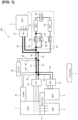
- Figure 1 is a schematic structural view of a device 100 for controlling a hybrid vehicle according to a first embodiment of the present invention.
- the device 100 for controlling a hybrid vehicle is configured from an engine 1, an electric power generator (electric power source) 2, an electric power generator inverter 21, a front drive motor 3, a front inverter 31, a gearbox 4, a rear drive motor (drive motor) 5, a rear inverter 51, a battery device 6, a controller 7, etc.
- the electric power generator 2 and the rear drive motor 5 are electrically connected via a front harness (harness) 81 and a rear harness 82, and the electric power generator 2 and the battery device 6 are electrically connected via the front harness 81.
- the front harness 81 and the rear harness 82 are high-power electric harnesses for connecting electric components of a high-power electric system.
- FIG. 1 shows a structural example in which a control device 100 is used in a "series hybrid vehicle," in which the electric power generator 2 is driven using motive power of the engine 1, electric power generated by the electric power generator 2 is supplied to the battery device 6, and the drive motors 3, 5 are caused to rotate on the basis of the electric power of the battery device 6.
- the engine 1 links to an electric-power-generating motor of the electric power generator 2 via a gear train (not shown) inside the gearbox 4, and transmits motive power for the electric power generator 2 to generate electric power, to the electric-power-generating motor of the electric power generator 2.
- the electric power generator 2 generates electric power due to the electric-power-generating motor (a three-phase AC motor) being rotatably driven by the motive power transmitted from the engine 1.
- the electric power generator 2 is electrically connected to the electric power generator inverter 21, and the electric power generator inverter 21 is electrically connected to the battery device 6.
- the electric power generated by the electric power generator 2 is charged in batteries 61, 62 inside the battery device 6 via the electric power generator inverter 21.
- the electric power charged in the batteries 61, 62 is used for the motive power of the drive motors 3, 5.
- the electric power generator inverter 21 is electrically connected to the front drive motor 3 and the rear drive motor 5, and to the front inverter 31 and the rear inverter 51 respectively electrically connected to the motors.
- the electric power generator 2 is electrically connected to the drive motors 3, 5 via the inverters 21, 31, 51.
- the electric power generated by the electric power generator 2 can thereby be directly supplied to the front drive motor 3 and the rear drive motor 5 without being routed through the battery device 6.
- the electric power generated by the electric power generator 2 is directly supplied to the drive motors 3, 5 in cases such as when there is an electric power requirement for the drive motors 3, 5 while the battery device 6 (the batteries 61, 62) is charging, or when a large amount of driving force is required as in a time of high load and the driving force requirement cannot be satisfied by electric power from the battery device 6 alone.
- the electric power generator inverter 21 is electrically connected to the electric power generator 2, the battery device 6, the front inverter 31, and the rear inverter 51, and the electric power generator inverter 21 converts AC electric power generated by the electric power generator 2 to DC electric power.
- the electric power of the electric power generator 2 converted to DC by the electric power generator inverter 21 is supplied to the battery device 6.
- the electric power of the electric power generator 2 converted to DC by the electric power generator inverter 21 is supplied to the front inverter 31 and the rear inverter 51 and is converted to AC in the inverters 31, 51.
- the electric power converted to AC is supplied to the front drive motor 3 and the rear drive motor 5.
- the electric power generator 2 and the electric power generator inverter 21 function as electric power sources that supply charging electric power for the battery device 6 and driving electric power for the drive motors 3, 5.
- the front drive motor 3 (a three-phase AC motor) electrically connects to the battery device 6 via the front inverter 31, and links to front wheels of the vehicles via a gear train (not shown) separate from the gear train linking the engine 1 and the electric power generator 2 inside the gearbox 4. Electric power is supplied to the front drive motor 3 from the battery device 6, the front drive motor 3 rotates due to the electric power supplied from the battery device 6, and driving force is generated. The driving force generated by this rotation is transmitted to the front wheels via the gear train, and the front wheels are driven.
- a gear train not shown
- the front drive motor 3 electrically connects also to the electric power generator 2 via the electric power generator inverter 21 and the electric power generator inverter 21.
- the electric power generated by the electric power generator 2 is directly supplied to the front drive motor 3 and the front wheels are driven.
- driving force of the front drive motor 3 is regeneratively generated as electric energy, and the regenerative electric power is charged in the battery device 6 (batteries 61, 62) via the front inverter 31.
- the front inverter 31 electrically connects to the front drive motor 3, the battery device 6, and the electric power generator inverter 21.
- the front inverter 31 is a driving inverter that converts DC electric power from the battery device 6, or electric power generated by the electric power generator 2 and converted to DC by the electric power generator inverter 21, to AC and supplies the AC power to the front drive motor 3.
- the front inverter 31 also converts AC electric power regeneratively generated by the front drive motor 3 to DC electric power and supplies the DC power to the battery device 6.
- the gearbox 4 is a gear device that includes gear trains composed of a plurality of gears. Accommodated in the gearbox 4 are a gear train linking the engine 1 and the electric power generator 2, and a gear train linking the front drive motor 3 and the front wheels.
- two gear trains are accommodated within one gearbox 4, whereby oil can be efficiently supplied to the gear trains and oil can be conserved.
- the two gear trains are preferably accommodated within one gearbox 4, but this example is not provided by way of limitation.
- the configuration may be such that the gear train linking the engine 1 and the electric power generator 2 and the gear train linking the front drive motor 3 and the front wheels are accommodated in separate gearboxes.
- the rear drive motor 5 (a three-phase AC motor) electrically connects to the battery device 6 via the rear inverter 51, and links to rear wheels of the vehicle via a gear train (not shown).
- a gear train (not shown).
- the rear drive motor 5 electrically connects also to the electric power generator 2 via the rear inverter 51 and the electric power generator inverter 21, and when necessary, electric power generated by the electric power generator 2 is directly supplied to the rear drive motor 5 and the rear wheels are driven.
- the front drive motor 3 when the vehicle is decelerating, driving force of the rear drive motor 5 is regeneratively generated as electric energy, and the regenerative electric power is charged in the battery device 6 (batteries 61, 62) via the rear inverter 51.
- the rear inverter 51 electrically connects to the rear drive motor 5, the battery device 6, and the electric power generator inverter 21.
- the rear inverter 51 is a driving inverter that converts DC electric power from the battery device 6, or electric power generated by the electric power generator 2 and converted to DC by the electric power generator inverter 21, to AC and supplies the AC power to the rear drive motor 5.
- the rear inverter 51 also converts AC electric power regeneratively generated by the rear drive motor 5 to DC electric power and supplies the DC power to the battery device 6.
- the battery device (vehicle electrical equipment) 6 is a battery pack including batteries 61, 62 of a secondary cell, relays 63, an SD switch 64, etc.
- the batteries 61, 62 are high-power batteries that supply stored electric power to the drive motors 3, 5, and are electrically connected to the electric power generator 2, the front drive motor 3, and the rear drive motor 5.
- the battery 61 and the battery 62 are electrically connected via the SD switch 64.
- the electric power generated by the electric power generator 2 and the regenerative electric power of the drive motors 3, 5 are charged in the batteries 61, 62, and electric power charged in the batteries 61, 62 is supplied to the front drive motor 3 and the rear drive motor 5.
- the front drive motor 3 and the rear drive motor 5 are rotatably driven by the electric power supplied from the batteries 61, 62, and the hybrid vehicle travels due to motive power of the drive motors 3, 5.
- the electric power generated by the electric power generator 2 is directly supplied to the drive motors 3, 5.
- the electric power of the batteries 61, 62 and the electric power generated by the electric power generator 2 are supplied to the drive motors 3, 5 and are both used.
- the relays 63 are installed near the batteries 61, 62 on wiring connecting the batteries 61, 62 with the electric power generator 2, the front drive motor 3, and the rear drive motor 5.
- the relays 63 are capable of opening and closing so as to switch between a state of allowing electrical continuity between the batteries 61, 62 and the electric power generator 2, front drive motor 3, and rear drive motor 5 (an ON state), and a state of electrically cutting off the aforementioned components (an OFF state).
- the SD switch 64 is a switch that manually or automatically sets circuits of the batteries 61, 62 to OFF in times such an emergency, and is provided on the wiring electrically connecting the battery 61 and the battery 62.
- the battery device 6 is provided with an electric current sensor (not shown) that detects electric current values of the batteries 61, 62.
- the electric current values detected by the electric current sensor are sent to the controller 7 (described hereinafter).
- the controller 7 is, for example, a vehicle control module (VCM), and the controller 7 integrally controls, inter alia, the reception of the supply of electric power for the entire hybrid vehicle, and the actions of the engine 1, the electric power generator 2, and the drive motors 3, 5.
- VCM vehicle control module
- the controller 7 is configured from a microcomputer provided with a central processing device (CPU), read-only memory (ROM), random-access memory (RAM), and an input/output interface (I/O interface).
- the controller 7 can also be configured from a plurality of microcomputers. By executing a specific program, the controller 7 executes a process for controlling the entire device 100 for controlling a hybrid vehicle. For example, the controller 7 executes a process for protecting the harness (described hereinafter).
- the electric-power-generating motor of the electric power generator 2, the front drive motor 3, and the rear drive motor 5 are each provided with a resolver, an encoder, or another speed detection device, and the speed detection devices detect the speed of the motors.
- the detected motor speeds are sent to the controller 7.
- electric current sensors (not shown) are installed.
- the electric current sensors detect AC electric currents of the motors, and the detected electric current values are sent to the controller 7.
- the electric current sensors may detect the AC electric currents of the three phases, or may detect the electric currents of any two phases and the electric current of the remaining phase may be computed and determined by the controller 7.
- Voltage sensors (not shown) are attached to DC-end sides of the electric power generator inverter 21, the front inverter 31, and the rear inverter 51, and the voltage sensors detect DC-end voltages of the inverters. The detected voltage values are sent to the controller 7.
- the electric power generator inverter 21 and the front inverter 31 are electrically connected by busbars 83, as shown in Figure 1 . Electric power generated by the electric power generator 2 can thereby be supplied to the front drive motor 3 via the busbars 83.
- the electric power generator inverter 21, the front inverter 31, and the batteries 61, 62 are electrically connected by the busbars 83, busbars 84, and two front harnesses 81 linking the busbars 83 and the busbars 84. Relays 63 are provided in proximity to the batteries 61, 62 on the busbars 84. Furthermore, the electric power generator inverter 21 and the rear inverter 51 are electrically connected by the busbars 83, the busbars 84, the two front harnesses 81 linking the busbars 83 and the busbars 84, and two rear harnesses 82 connected to the busbars 84.
- the batteries 61, 62 and the rear drive motor 5 are connected to the electric power generator 2, which is an electric power source, via the same front harnesses 81. Due to this configuration, the electric power generated by the electric power generator 2 and the electric power regenerated by the front drive motor 3 are charged in the batteries 61, 62 via the front harnesses 81, and the electric power regenerated by the rear drive motor 5 is charged in the batteries 61, 62 via the rear harnesses 82. The electric power charged in the batteries 61, 62 is supplied to the front drive motor 3 via the front harnesses 81 and supplied to the rear drive motor 5 via the rear harnesses 82. In addition, when electric power is supplied from the electric power generator 2 to the rear drive motor 5, the electric power generated by the electric power generator 2 is supplied to the rear drive motor 5 via the front harnesses 81 and the rear harnesses 82.
- An air compressor 91 or another vehicle electrical equipment (auxiliary equipment) may be connected to the busbars 83 via harnesses 85, as shown in Figure 1 .
- a DC/DC converter 92 or another vehicle electrical equipment (auxiliary equipment) may be connected to the busbars 84 via harnesses 86. Electric power generated by the electric power generator 2 may be supplied to the air compressor 91, the DC/DC converter 92, or other vehicle electrical equipment via the electric power generator inverter 21.
- the batteries 61, 62, the rear drive motor 5, and the electric power generator 2, which is an electric power source are connected using high-power electric harnesses (the front harnesses 81 and the rear harnesses 82).
- the harness coating crosslinked polyethylene, silicone rubber, etc.
- the harness coating has a heatproof temperature restriction; when a large amount of electric power is passing through the harnesses, the temperature of the harnesses rises and there is a risk that the heatproof temperature of the harness coatings (referred to below as the heatproof temperature of the harnesses) will be exceeded.
- the batteries 61, 62 and the rear drive motor 5 are connected to the electric power generator 2 via the same front harnesses 81. Accordingly, when charging of the batteries 61, 62 and electric power supply to the rear drive motor 5 must be done simultaneously, the electric power generated by the electric power generator 2 is supplied to the batteries 61, 62 and the rear drive motor 5 via the same front harnesses 81. Therefore, a large amount of electric power passes through the front harnesses 81, the front harnesses 81 rise in temperature, and there is a risk that the heatproof temperature will be exceeded. If busbars are used in all of the wiring, the heatproof temperature restriction is nearly eliminated, but it is difficult to use only busbars in locations where the wiring distance is long (for example, several meters) due to problems of workability and maneuverability.
- the batteries 61, 62 and the rear drive motor 5 can be connected to the electric power generator 2 using separate harnesses, but there would be problems such as more complicated wirings and a greater number of wirings, which is undesirable from a standpoint of vehicle weight reduction, etc.
- Scenarios in which the charging of the batteries 61, 62 and the electric power supply to the rear drive motor 5 must be done simultaneously are by nature limited to cases such as when, for example, the batteries 61, 62 have a low SOC and need charging, the accelerator is depressed by the driver, and there is an electric power requirement for the rear drive motor 5.
- the charging electric power for the batteries 61, 62 and the driving electric power for the rear drive motor 5 do not simultaneously pass through the front harnesses 81.
- the restriction of the electric power supply to the batteries 61, 62 is further increased and the restriction of the electric power supply to the rear drive motor 5 is further reduced. It is thereby possible to maintain electric power supply to the rear drive motor 5 while restricting the electric power passing through the front harnesses 81. Specifically, it is possible to minimize any discomfort or dissatisfaction experienced by the driver, etc., while minimizing the temperature increase of the front harnesses 81.
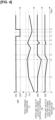
- Figure 2 shows graphs illustrating a control for harness protection according to the present embodiment, and this graph shows the restriction of the electric power supplied from the electric power generator 2 to the rear drive motor 5 and the batteries 61, 62, corresponding to the temperature increase in the front harnesses 81.
- Figure 2 is also graphs illustrating control executed in a scenario in which charging of the batteries 61, 62 and electric power supply to the rear drive motor 5 are done simultaneously.
- Graph (a) in Figure 2 shows the restriction of the upper limit value of electric power outputted to the rear drive motor 5 corresponding to the temperature increase in the front harnesses 81
- graph (b) shows the restriction of the upper limit value of electric power outputted to the battery device 6 corresponding to the temperature increase in the front harnesses 81.
- the curves in these graphs represent upper limit values of electric power outputted from the electric power generator 2 to the rear drive motor 5 and the batteries 61, 62, and the upper limit values of electric power outputted to rear drive motor 5 and the batteries 61, 62 are both 100% when there is no output restriction.
- the predetermined temperature T th mentioned here is a temperature (e.g., a value 5°C lower than the heatproof temperature of the front harnesses 81) at which, if the temperature of the front harnesses 81 continues to rise, there is a risk that a critical value of the heatproof temperature of the front harnesses 81 will be reached within a certain period of time, although not immediately.
- the critical temperature T max is set to a critical value of the heatproof temperature of the front harnesses 81 or to a temperature near the heatproof temperature of the front harnesses 81, which is slightly lower than the heatproof temperature.
- the temperature of the front harnesses 81 is estimated from the value of electric current flowing through the front harnesses 81. The details of estimating the temperature of the front harnesses 81 shall be described hereinafter.
- the restriction of the upper limit value of electric power outputted to the rear drive motor 5 is carried out by reducing the upper limit value of required torque of the rear drive motor 5.
- the upper limit value of required torque of the rear drive motor 5 is reduced as the temperature of the front harnesses 81 rises.
- the upper limit value of electric power outputted to the rear drive motor 5 is thereby reduced as the temperature of the front harnesses 81 increases when the front harnesses 81 are in the range (restriction range R) from the predetermined temperature T th to the critical temperature T max (inclusive), as shown in Figure 2 .
- T max the supply of electric power from the electric power generator 2 is cut off.
- the upper limit value of charging electric power supplied to the batteries 61, 62 is also reduced simultaneously with the reduction of electric power outputted to the rear drive motor 5, as shown in Figure 2 .
- the degree of reduction in the upper limit value of electric power supplied to the batteries 61, 62 is greater than the degree of reduction in the upper limit value of electric power supplied to the rear drive motor 5.
- the degree of reduction mentioned here is, for example, a reduction rate in the upper limit value with respect to the upper limit value of the outputted electric power before the restriction of the outputted electric power is initiated, or a reduction rate in the upper limit value (i.e., the absolute value of the slope of the curve of Figure 2 ) when the temperature of the front harnesses 81 has risen by a unit temperature.
- the upper limit value of the outputted electric power before the restriction of the outputted electric power is initiated is designated as 100%, in the restriction range R, the upper limit value of electric power outputted to the batteries 61, 62 is always smaller (i.e., the reduction rate of the upper limit value is greater) than the upper limit value of electric power outputted to the rear drive motor 5, as shown in Figure 2 .
- the degree of reduction in the upper limit value of electric power supplied to the batteries 61, 62 is greater than the degree of reduction in the upper limit value of electric power supplied to the rear drive motor 5.
- the upper limit value of electric power supplied to the rear drive motor 5 when the temperature of the front harnesses 81 reaches T max is established on the basis of the electric power at which balanced is reached, i.e., the supplied electric power at which heat generation and heat dissipation in the front harnesses 81 are balanced.
- electric power further reduced by such error from the electric power at which balance is reached may be set as the upper limit value of electric power supplied to the rear drive motor 5.
- the upper limit value of required torque of the rear drive motor 5 is reduced on the basis of the temperature of the rear harnesses 82 so that the temperature of the rear harnesses 82 will not exceed the heatproof temperature. Due to this action, the upper limit value of electric power supplied to the rear harnesses 82 is reduced, and the temperature of the rear harnesses 82 is minimized.
- the relays 63 are switched to an OFF state, the electric power supply from the batteries 61, 62 to the rear drive motor 5 is cut off, and the electric power supply from the electric power generator 2 to the rear drive motor 5 is also cut off.
- FIG. 3 is a flowchart illustrating the control for harness protection according to the present embodiment. The following control is executed repeatedly at predetermined time intervals by the controller (VCM) 7.
- VCM controller
- the control for harness protection is initiated by the controller 7 receiving a command to start up the device 100 for controlling a hybrid vehicle. For example, when an ON operation of switching an ignition key of the vehicle from OFF to ON is performed, a startup command is sent to the controller 7.
- Steps S101-S104 are steps for estimating the temperature of the front harnesses 81.
- a temperature change ⁇ T in the temperature T of the harnesses can be determined through the following formula (1), from the difference between a heat generation amount (r/C p )I 2 and a heat dissipation amount (hA/C p ) (T-T ⁇ ) in the harnesses.
- ⁇ t represents time elapsed from the previous temperature estimation
- r/C p represents a heat generation coefficient
- hA/C p represents a heat dissipation coefficient
- T represents an estimated temperature at the time of the previous estimation (previous estimated temperature)
- T ⁇ represents an ambient temperature around the harnesses.
- the heat generation coefficient r/C p and the heat dissipation coefficient hA/C p are constants unique to the harnesses and are fixed values.
- the ambient temperature around the harnesses may be an actually measured value, but a fixed value appropriately determined in advance by experimentation, etc., may be used.
- the temperature change ⁇ T of the harnesses can be estimated from the value I of electric current flowing through the harnesses.
- the temperature of the harnesses can also be determined by adding the previous estimated temperature T and the temperature change ⁇ T in the harnesses.
- the value I of electric current flowing through the harnesses is first estimated, and the temperature of the harnesses is estimated from the estimated value of the electric current.
- step S101 the controller 7 acquires: the speeds of the power-generating motor of the electric power generator 2, the front drive motor 3, and the rear drive motor 5; the electric current values and DC-end voltage values of the electric power generator inverter 21, the front inverter 31, and the rear inverter 51; and the electric current values of the batteries 61, 62.
- the controller 7 also estimates the torques of the motors from the acquired electric current values of the inverters.
- step S102 the controller 7 estimates the DC voltage values of the electric power generator inverter 21, the front inverter 31, and the rear inverter 51 on the basis of the speeds and torques of the motors and the DC-end voltage values of the inverters.
- the DC electric current values of the front inverter 31 and the rear inverter 51 are equivalent to the DC electric current values of the busbars 83 and the rear harnesses 82.
- step S103 the controller 7 estimates the values of DC electric current flowing through the front harnesses 81 and the rear harnesses 82 on the basis of the estimated DC electric current values of the inverters. Specifically, when charging the batteries 61, 62 and supplying electric power to the rear drive motor 5 are done simultaneously, a DC electric current value I FrHAR of the front harnesses 81 is estimated using formula (2) below, in which an input electric current I LBCin of the batteries 61, 62 and an input electric current I Rrin of the rear inverter 51 are added.
- a DC electric current value I RrHAR of the rear harnesses 82 is estimated using formula (3) below, in which input electric currents I Frin , I LBCin of the front inverter 31 and the batteries 61, 62 are subtracted from an output electric current I GENout of the electric power generator inverter 21.
- I FrHAR I LBCin + I Rrin
- I FrHAR I GENout ⁇ I Frin ⁇ I LBCin
- the DC electric current value I FrHAR of the front harnesses 81 is estimated using formula (4) below, in which the input electric current I Rrin of the rear inverter 51 is subtracted from an output electric current I LBCout of the batteries 61, 62.
- the DC electric current value I RrHAR of the rear harnesses 82 is estimated using formula (5) below, in which the input electric current I Frin of the front inverter 31 is subtracted from the output electric current I LBCout of the batteries 61, 62.
- the DC electric current value I FrHAR of one the front harnesses 81 is estimated using formula (6) below, in which the input electric current I Frin of the front inverter 31 is subtracted from the output electric current I GENout of the electric power generator inverter 21, and the same value of the other of the front harnesses 81 is estimated using formula (7) below, in which the input electric current I Rrin of the rear inverter 51 is subtracted from the output electric current I LBCout of the batteries 61, 62.
- the DC electric current value I RrHAR of the rear harnesses 82 is estimated using formula (8) below, in which the which the input electric current I Frin of the front inverter 31 is subtracted from the sum of the output electric current I LBCout of the batteries 61, 62 and the output electric current I GENout of the electric power generator 2.
- I FrHAR I GENout ⁇ I Frin
- I FrHAR I LBCout ⁇ I Rrin
- I RrHAR I LBCout + I GENout ⁇ I Frin
- step S103 when the values I FrHAR , I RrHAR of DC electric current flowing through the front harnesses 81 and the rear harnesses 82 are estimated, the controller 7 executes the process of step S104.
- step S104 the controller 7 estimates the temperatures of the harnesses 81, 82 on the basis of the values I FrHAR , I RrHAR of DC electric current flowing through the front harnesses 81 and the rear harnesses 82. Specifically, formula (1) previously described is used to calculate the temperature changes ⁇ T in the harnesses 81, 82, and the previous estimated temperatures T and the temperature changes ⁇ T are added to estimate the temperatures of the harnesses 81, 82.
- the ambient temperature T ⁇ around the harnesses is used for an initial value of the previous estimated temperature T.
- the heat dissipation amount (hA/C p ) (T-T ⁇ ) is zero. Accordingly, a value obtained by multiplying an elapsed time ⁇ t since startup of the control device 100 by the heat generation amount (r/C p )I 2 in the harnesses 81, 82 is the temperature change ⁇ T, and a value obtained by adding the temperature change ⁇ T and the ambient temperature T ⁇ around the harnesses (the previous estimated temperature T) is a harness estimated temperature.
- Steps S105-S107 are steps in which the electric power supply is controlled on the basis of the temperature of the harnesses.
- the controller 7 assesses whether the temperatures of the harnesses 81, 82 have not exceeded the critical temperature T max .
- the critical temperature T max is either a critical value of the heatproof temperature of the harnesses 81, 82, or is set for each of the harnesses 81, 82 and is set to a temperature that is slightly lower than the heatproof temperature of the harnesses 81, 82 and that is near the heatproof temperature.
- step S106 the controller 7 switches the relays 63 to the OFF state and cuts off the electric power supply from the electric power generator 2 to the batteries 61, 62 or the electric power supply from the batteries 61, 62 to the drive motors 3, 5. At the same time, the controller 7 cuts off the electric power supply from the electric power generator 2 to the rear drive motor 5. Upon cutting off these electric power supplies, the controller 7 ends the control for harness protection.
- step S107 When neither of the temperatures of the front harnesses 81 and the rear harnesses 82 exceeds T max , the controller 7 executes the process of step S107.
- step S107 the controller 7 assesses whether or not the temperature of the front harnesses 81 is equal to or greater than the predetermined temperature T th .
- the predetermined temperature T th is a temperature at which even if the front harnesses 81 further rise in temperature, the critical value of the heatproof temperature of the front harnesses 81 is not immediately reached, and the predetermined temperature T th is set in advance by experimentation, etc.
- the controller 7 executes the process of step S108.
- the controller 7 executes the process of step S109.
- step S108 the controller 7 restricts the electric power outputted from the electric power generator 2. Specifically, on the basis of the temperature of the front harnesses 81, the upper limit value or the required torque of the rear drive motor 5 and the upper limit value of electric power outputted to the batteries 61, 62 (input electric power of the batteries 61, 62) are reduced. As previously described, the upper limit value of electric power outputted from the electric power generator 2 to the rear drive motor 5 is also reduced by reducing the upper limit value of the required torque of the rear drive motor 5.
- the controller 7 reduces the upper limit value of the required torque of the rear drive motor 5 and the upper limit value of electric power outputted to the batteries 61, 62 so that the degree of reduction in the upper limit value of electric power outputted to the batteries 61, 62 is greater than the degree of reduction in the upper limit value of electric power outputted to the rear drive motor 5. It is thereby possible to keep the reduction of driving electric power supplied to the rear drive motor 5 to a minimum while minimizing any temperature increase in the front harnesses 81.
- step S108 when only the electric power supplied from the electric power generator 2 to the rear drive motor 5 is passing through the front harnesses 81, the controller 7 reduces the upper limit value of electric power outputted by the electric power generator 2 on the basis of the temperature of the front harnesses 81.
- the electric power outputted by the batteries 61, 62 may be controlled so that the reduced amount of electric power is supplied from the batteries 61, 62 to the rear drive motor 5.
- step S107 when only the electric power supplied from the batteries 61, 62 to the front drive motor 3 is passing through the front harnesses 81, the controller 7 reduces the upper limit value of electric power supplied from the batteries 61, 62 to the front drive motor 3 on the basis of the temperature of the front harnesses 81.
- the temperature of the front harnesses 81 will not be equal to or greater than the predetermined temperature T th .
- the controller 7 assesses in step S109 whether or not the temperature of the rear harnesses 82 is equal to or greater than the predetermined temperature T th .
- the predetermined temperature T th mentioned here is a temperature at which even if the rear harnesses 82 further rise in temperature, the critical value of the heatproof temperature of the rear harnesses 82 is not immediately reached, and the predetermined temperature T th is set in advance by experimentation, etc.
- the controller 7 executes the process of step S110.
- the controller 7 ends the control for harness protection, and after a predetermined time has elapsed, the controller 7 again executes the processes from step S101 onward.
- step S110 the controller 7 restricts the electric power supplied to the rear drive motor 5. Specifically, the upper limit value of the required torque of the rear drive motor 5 is reduced on the basis of the temperature of the rear harnesses 82. As a result, the upper limit value of electric power supplied to the rear drive motor 5 is reduced and any temperature increase in the rear harnesses 82 is minimized.
- step S108 When at least one of the temperature of the front harnesses 81 and the temperature of the rear harnesses 82 is equal to or greater than T th , the reduction of the upper limit value of the electric power outputted by the electric power generator 2 in step S108 and the reduction of the upper limit value of the electric power supplied to the rear drive motor 5 in step S110 may be executed. Specifically, the processes of step S107 and step S109 are performed simultaneously, and when at least one of the temperature of the front harnesses 81 and the temperature of the rear harnesses 82 is equal to or greater than the temperature T th , the processes of step S108 and step S110 may be executed.
- the predetermined temperature T th in step S107 and the predetermined temperature T th in step S109 may be set to different values.
- the threshold value of the temperature of the front harnesses 81 (the predetermined temperature T th in step S107) is preferably set to a value smaller than the threshold value of the temperature of the rear harnesses 82 (the predetermined temperature T th in step S109). It is thereby possible to further minimize any discomfort or dissatisfaction experienced by the driver, etc., while reliably minimizing any temperature increase in the front harnesses 81.
- step S110 When the process of step S110 is executed, the controller 7 ends the control for harness protection, and after a predetermined time has elapsed, the controller 7 again executes the processes from step S101 onward.
- the control for harness protection is stopped due to the controller 7 receiving a command to stop the device 100 for controlling a hybrid vehicle. For example, when a stop operation is performed in which the ignition key of the vehicle is switched to OFF, a stop command is sent to the controller 7.
- the estimated temperature T at the time of the previous estimation may use the ambient temperature T ⁇ , which is a fixed value, or may use the estimated temperature at the time of the stop. For example, the estimated temperature at the time of the stop may be used when the vehicle is again started up within a predetermined time following the stop.
- Figure 4 is a timing chart illustrating the control for harness protection according to the first embodiment.
- the ignition switch (IGN) is switched to OFF, and the controller 7 (VCM) stops at time t7. Even after the ignition switch (IGN) has been switched to OFF, the controller 7 (VCM) maintains the harness temperatures until the controller 7 stops (t6-t7).
- the following effects can be achieved.
- the device 100 for controlling a hybrid vehicle when a temperature of front harnesses (harnesses) 81 is equal to or greater than a predetermined temperature, upper limit values of electric power supplied from an electric power generator (an electric power source) 2 to batteries (a vehicle electrical equipment) 61, 62 and a rear drive motor (a drive motor) 5 are reduced.
- a degree of reduction in the upper limit value for the batteries (a vehicle electrical equipment) 61, 62 is greater than a degree of reduction in the upper limit value for the rear drive motor (a drive motor) 5.
- the electric power supply from the electric power generator (an electric power source) 2 to the batteries (a vehicle electrical equipment) 61, 62 is restricted to an even greater extent, and a restriction of the electric power supply to the rear drive motor (a drive motor) 5 is further reduced. It is thereby possible to keep the reduction in driving electric power supplied to the rear drive motor (a drive motor 5) to a minimum while minimizing any temperature increase in the front harnesses (harnesses) 81. Accordingly, any discomfort or dissatisfaction experienced by the driver, etc., can be minimized while minimizing any temperature increase in the front harnesses (harnesses) 81.
- estimations of the temperatures of the harnesses 81, 82 are performed on the basis of the values of electric currents flowing through the harnesses 81, 82, but this example is not provided by way of limitation as to the method of estimating the temperatures of the harnesses 81, 82; any known method may be used. If possible, the temperatures of the harnesses 81, 82 may be measured.
- DC electric current values of inverters 21, 31, 51 are estimated, and the values of electric currents flowing through the harnesses 81, 82 are estimated on the basis of these estimated values and input/output electric current values of the batteries 61, 62, but this example is not provided by way of limitation.
- the values of electric currents flowing through the harnesses 81, 82 may be estimated using any known method. If possible, the electric current values of the harnesses 81, 82 may be measured.
- the upper limit value of electric power supplied from the electric power generator 2 to the rear drive motor 5 and the upper limit value of electric power supplied to the batteries 61, 62 are reduced in linear fashion, but this example is not provided by way of limitation.
- a plurality of threshold values may be provided for the temperature of the front harnesses 81 and the upper limit values may be reduced in stepwise fashion when the threshold values are reached.
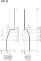
- a hybrid vehicle device 100 for controlling a hybrid vehicle according to a second embodiment shall be described with reference to Figure 5 .
- the present embodiment differs from the first embodiment in that when the electric power supplied from the electric power generator (electric power source) 2 to the rear drive motor 5 falls below the required electric power of the rear drive motor 5, the electric power supplied from the electric power generator (electric power source) 2 to the front drive motor 3 is increased.
- the same elements as those in the first embodiment are designated by the same reference numerals, and the descriptions thereof are omitted.
- Figure 5 shows graphs illustrating the control for harness protection according to the second embodiment, and these graphs show relationships of the temperature of the front harnesses 81 to the upper limit value of electric power supplied to the rear drive motor 5 and to the required electric power of the front drive motor 3.
- the graphs of Figure 5 illustrate control executed in a scenario in which charging of the batteries 61, 62 and electric power supply to the rear drive motor 5 are done simultaneously.
- Figure 5(a) shows a relationship between the temperature of the front harnesses 81 and the upper limit value of electric power outputted to the rear drive motor 5
- Figure 5(b) shows a relationship between the temperature of the front harnesses 81 and the required electric power of the front drive motor 3.
- the degree of reduction in the upper limit value of electric power supplied to the batteries 61, 62 is greater than the degree of reduction in the upper limit value of electric power supplied to the rear drive motor 5.
- the electric power supplied to the rear drive motor 5 decreases due to the upper limit value of electric power supplied to the rear drive motor 5 being reduced, and when the required torque of the rear drive motor 5 cannot be satisfied, the required torque of the front drive motor 3 is increased by the difference between the required torque of the rear drive motor 5 and the actual torque. Due to these actions, the driving force of the entire vehicle can be maintained, and any discomfort for the driver, etc., is minimized.
- the required torque of the front drive motor 3 is increased by the difference between the required torque of the rear drive motor 5 and the actual torque.
- the required electric power of the front drive motor 3 rises by the difference between the required electric power of the rear drive motor 5 and the electric power supplied to the rear drive motor 5 (the upper limit value of electric power supplied to the rear drive motor 5), and the electric power supplied from the electric power generator 2 to the front drive motor 3 is increased.
- the electric power supplied from the electric power generator 2 to the front drive motor 3 is increased by the difference ⁇ P between the required electric power Pn of the rear drive motor 5 and the upper limit value P 1 of electric power supplied to the rear drive motor 5.
- the electric power needed for the increased required torque of the front drive motor 3 is supplied from the electric power generator 2 to the front drive motor 3.
- the following effects can be achieved.
- the front drive motor 3 is electrically connected to the electric power generator (an electric power source) 2 without being routed through the front harnesses (harnesses) 81.
- the temperature of the front harnesses (harnesses) 81 is equal to or greater than a predetermined temperature, upper limit values of electric power supplied from the electric power generator (an electric power source) 2 to the vehicle electrical equipment (batteries 61, 62) and to the rear drive motor 5 are both reduced.
- the electric power supplied from the electric power generator (an electric power source) 2 to the front drive motor 3 is increased by the difference between the required electric power of the rear drive motor 5 and the electric power supplied to the rear drive motor 5.
- the electric power supplied to the front drive motor 3 is increased and the shortage of electric power supplied to the rear drive motor 5 is compensated for. Accordingly, the electric power supplied overall to the drive motors 3, 5 does not decrease; therefore, required torque can be satisfied and driving force can be maintained for the entire vehicle.
- the front drive motor 3 is increased, the front drive motor 3 being able to supply electric power without supplying through the front harnesses (harnesses) 81; therefore, electric power passing through the front harnesses (harnesses) 81 is not increased, and electric power satisfying the torque required for the entire vehicle can be supplied to the drive motors 3, 5.
- the upper limit value of electric power supplied to the rear drive motor 5 can be reduced to maintain the driving force for the entire vehicle while restricting the electric power passing through the front harnesses (harnesses) 81. Accordingly, any discomfort or dissatisfaction experienced by the driver, etc., can be further minimized while minimizing the temperature of the front harnesses (harnesses) 81.
- the electric power source that supplies electric power to the batteries 61, 62 was the electric power generator 2, but the electric power generator 2 is not provided by way of limitation on the electric power source, which may, for example, be a fuel cell, etc.
- the vehicle electrical equipment to which electric power is supplied from the electric power generator (an electric power source) 2 was the high-power batteries 61, 62, but the high-power batteries 61, 62 are not provided by way of limitation as to the destination of electric power supplied from the electric power generator (an electric power source) 2.
- electric power may be supplied from the electric power generator (an electric power source) 2 via the front harnesses (harnesses) 81 to auxiliary equipment actuated by high electric power, or electric power may be supplied to non-high-power auxiliary equipment.
- the upper limit values of electric power supplied to the auxiliary equipment and the rear drive motor (a drive motor) 5 are reduced.
- the degree of reduction in the upper limit value for the auxiliary equipment is increased above the degree of reduction in the upper limit value for the rear drive motor (a drive motor) 5.
Landscapes
- Engineering & Computer Science (AREA)
- Mechanical Engineering (AREA)
- Transportation (AREA)
- Chemical & Material Sciences (AREA)
- Combustion & Propulsion (AREA)
- Automation & Control Theory (AREA)
- Power Engineering (AREA)
- Health & Medical Sciences (AREA)
- Biomedical Technology (AREA)
- General Health & Medical Sciences (AREA)
- Sustainable Development (AREA)
- Sustainable Energy (AREA)
- Life Sciences & Earth Sciences (AREA)
- Electric Propulsion And Braking For Vehicles (AREA)
Abstract
Description
- The present invention relates to a method and device for controlling a hybrid vehicle.
- In a hybrid vehicle, etc., provided with a configuration in which electric power is supplied from an electric power source to a drive motor, a battery, or another electrical equipment via a wire harness (an electric wire, referred to below as a harness), there is a risk that a temperature of the harness will increase and exceed a heatproof temperature of the harness when the electric power supplied to the drive motor or electrical equipment is high.
- It is possible to thicken the harness to raise the heatproof temperature, but the harness increases in weight, which is undesirable in terms of vehicle weight reduction, etc. There is also the problem of incurring costs.
-
JP 2009-130944 A - In the technology described in
JP 2009-130944 A - The present invention was contrived in view of these problems, it being an object of the invention to provide a method and device for controlling a hybrid vehicle in which any discomfort or discontent experienced by the driver, etc., can be minimized while any temperature increase in the harness is minimized.
- According to one aspect of the present invention, there is provided a method for controlling a hybrid vehicle comprising an electric power source, and a vehicle electrical equipment and drive motor to which electric power is supplied from the electric power source. The vehicle electrical equipment and the drive motor are electrically connected to the electric power source via at least a shared harness. When a temperature of the harness is equal to or greater than a predetermined temperature, upper limit values of electric power supplied from the electric power source to the vehicle electrical equipment and the drive motor are both reduced, and a degree of reduction in the upper limit value for the vehicle equipment is greater than a degree of reduction in the upper limit value for the drive motor.
-
-
Figure 1 is a schematic structural view of a device for controlling a hybrid vehicle according to a first embodiment of the present invention; -
Figure 2 shows graphs illustrating a control for harness protection according to the first embodiment; -
Figure 3 is a flowchart illustrating the control for harness protection according to the first embodiment; -
Figure 4 is a timing chart illustrating the control for harness protection according to the first embodiment; and -
Figure 5 shows graphs illustrating the control for harness protection according to a second embodiment. - Embodiments of the present invention are described below with reference to drawings, etc.
-
Figure 1 is a schematic structural view of adevice 100 for controlling a hybrid vehicle according to a first embodiment of the present invention. - The
device 100 for controlling a hybrid vehicle is configured from an engine 1, an electric power generator (electric power source) 2, an electricpower generator inverter 21, a front drive motor 3, afront inverter 31, agearbox 4, a rear drive motor (drive motor) 5, arear inverter 51, a battery device 6, acontroller 7, etc. Theelectric power generator 2 and therear drive motor 5 are electrically connected via a front harness (harness) 81 and arear harness 82, and theelectric power generator 2 and the battery device 6 are electrically connected via thefront harness 81. Thefront harness 81 and therear harness 82 are high-power electric harnesses for connecting electric components of a high-power electric system. -
Figure 1 shows a structural example in which acontrol device 100 is used in a "series hybrid vehicle," in which theelectric power generator 2 is driven using motive power of the engine 1, electric power generated by theelectric power generator 2 is supplied to the battery device 6, and thedrive motors 3, 5 are caused to rotate on the basis of the electric power of the battery device 6. - The engine 1 links to an electric-power-generating motor of the
electric power generator 2 via a gear train (not shown) inside thegearbox 4, and transmits motive power for theelectric power generator 2 to generate electric power, to the electric-power-generating motor of theelectric power generator 2. - The
electric power generator 2 generates electric power due to the electric-power-generating motor (a three-phase AC motor) being rotatably driven by the motive power transmitted from the engine 1. Theelectric power generator 2 is electrically connected to the electricpower generator inverter 21, and the electricpower generator inverter 21 is electrically connected to the battery device 6. The electric power generated by theelectric power generator 2 is charged inbatteries power generator inverter 21. The electric power charged in thebatteries drive motors 3, 5. In addition, the electricpower generator inverter 21 is electrically connected to the front drive motor 3 and therear drive motor 5, and to thefront inverter 31 and therear inverter 51 respectively electrically connected to the motors. Specifically, theelectric power generator 2 is electrically connected to thedrive motors 3, 5 via theinverters electric power generator 2 can thereby be directly supplied to the front drive motor 3 and therear drive motor 5 without being routed through the battery device 6. For example, the electric power generated by theelectric power generator 2 is directly supplied to thedrive motors 3, 5 in cases such as when there is an electric power requirement for thedrive motors 3, 5 while the battery device 6 (thebatteries 61, 62) is charging, or when a large amount of driving force is required as in a time of high load and the driving force requirement cannot be satisfied by electric power from the battery device 6 alone. - The electric
power generator inverter 21 is electrically connected to theelectric power generator 2, the battery device 6, thefront inverter 31, and therear inverter 51, and the electricpower generator inverter 21 converts AC electric power generated by theelectric power generator 2 to DC electric power. The electric power of theelectric power generator 2 converted to DC by the electricpower generator inverter 21 is supplied to the battery device 6. When the electric power generated by theelectric power generator 2 is directly supplied to thedrive motors 3, 5, the electric power of theelectric power generator 2 converted to DC by the electricpower generator inverter 21 is supplied to thefront inverter 31 and therear inverter 51 and is converted to AC in theinverters rear drive motor 5. Thus, theelectric power generator 2 and the electric power generator inverter 21 function as electric power sources that supply charging electric power for the battery device 6 and driving electric power for thedrive motors 3, 5. - The front drive motor 3 (a three-phase AC motor) electrically connects to the battery device 6 via the
front inverter 31, and links to front wheels of the vehicles via a gear train (not shown) separate from the gear train linking the engine 1 and theelectric power generator 2 inside thegearbox 4. Electric power is supplied to the front drive motor 3 from the battery device 6, the front drive motor 3 rotates due to the electric power supplied from the battery device 6, and driving force is generated. The driving force generated by this rotation is transmitted to the front wheels via the gear train, and the front wheels are driven. - The front drive motor 3 electrically connects also to the
electric power generator 2 via the electricpower generator inverter 21 and the electricpower generator inverter 21. When necessary, the electric power generated by theelectric power generator 2 is directly supplied to the front drive motor 3 and the front wheels are driven. When the vehicle is decelerating, driving force of the front drive motor 3 is regeneratively generated as electric energy, and the regenerative electric power is charged in the battery device 6 (batteries 61, 62) via thefront inverter 31. - The
front inverter 31 electrically connects to the front drive motor 3, the battery device 6, and the electric power generator inverter 21. Thefront inverter 31 is a driving inverter that converts DC electric power from the battery device 6, or electric power generated by theelectric power generator 2 and converted to DC by the electricpower generator inverter 21, to AC and supplies the AC power to the front drive motor 3. Thefront inverter 31 also converts AC electric power regeneratively generated by the front drive motor 3 to DC electric power and supplies the DC power to the battery device 6. - The
gearbox 4 is a gear device that includes gear trains composed of a plurality of gears. Accommodated in thegearbox 4 are a gear train linking the engine 1 and theelectric power generator 2, and a gear train linking the front drive motor 3 and the front wheels. Thus, two gear trains are accommodated within onegearbox 4, whereby oil can be efficiently supplied to the gear trains and oil can be conserved. The two gear trains are preferably accommodated within onegearbox 4, but this example is not provided by way of limitation. Specifically, the configuration may be such that the gear train linking the engine 1 and theelectric power generator 2 and the gear train linking the front drive motor 3 and the front wheels are accommodated in separate gearboxes. - The rear drive motor 5 (a three-phase AC motor) electrically connects to the battery device 6 via the
rear inverter 51, and links to rear wheels of the vehicle via a gear train (not shown). When electric power is supplied to therear drive motor 5 from the battery device 6, therear drive motor 5 rotates, driving force generated by this rotation is transmitted to the rear wheels, and the rear wheels are driven. - The
rear drive motor 5 electrically connects also to theelectric power generator 2 via therear inverter 51 and the electricpower generator inverter 21, and when necessary, electric power generated by theelectric power generator 2 is directly supplied to therear drive motor 5 and the rear wheels are driven. As with the front drive motor 3, when the vehicle is decelerating, driving force of therear drive motor 5 is regeneratively generated as electric energy, and the regenerative electric power is charged in the battery device 6 (batteries 61, 62) via therear inverter 51. - The
rear inverter 51 electrically connects to therear drive motor 5, the battery device 6, and the electric power generator inverter 21. Therear inverter 51 is a driving inverter that converts DC electric power from the battery device 6, or electric power generated by theelectric power generator 2 and converted to DC by the electricpower generator inverter 21, to AC and supplies the AC power to therear drive motor 5. Therear inverter 51 also converts AC electric power regeneratively generated by therear drive motor 5 to DC electric power and supplies the DC power to the battery device 6. - The battery device (vehicle electrical equipment) 6 is a battery
pack including batteries relays 63, anSD switch 64, etc. Thebatteries drive motors 3, 5, and are electrically connected to theelectric power generator 2, the front drive motor 3, and therear drive motor 5. Thebattery 61 and thebattery 62 are electrically connected via theSD switch 64. The electric power generated by theelectric power generator 2 and the regenerative electric power of thedrive motors 3, 5 are charged in thebatteries batteries rear drive motor 5. The front drive motor 3 and therear drive motor 5 are rotatably driven by the electric power supplied from thebatteries drive motors 3, 5. As previously described, when there is an electric power requirement for thedrive motors 3, 5 while thebatteries electric power generator 2 is directly supplied to thedrive motors 3, 5. In cases such as a time of high load in which the driving force requirement cannot be satisfied by electric power from the battery device 6 alone, the electric power of thebatteries electric power generator 2 are supplied to thedrive motors 3, 5 and are both used. - The
relays 63 are installed near thebatteries batteries electric power generator 2, the front drive motor 3, and therear drive motor 5. Therelays 63 are capable of opening and closing so as to switch between a state of allowing electrical continuity between thebatteries electric power generator 2, front drive motor 3, and rear drive motor 5 (an ON state), and a state of electrically cutting off the aforementioned components (an OFF state). - The
SD switch 64 is a switch that manually or automatically sets circuits of thebatteries battery 61 and thebattery 62. - The battery device 6 is provided with an electric current sensor (not shown) that detects electric current values of the
batteries - The
controller 7 is, for example, a vehicle control module (VCM), and thecontroller 7 integrally controls, inter alia, the reception of the supply of electric power for the entire hybrid vehicle, and the actions of the engine 1, theelectric power generator 2, and thedrive motors 3, 5. - The
controller 7 is configured from a microcomputer provided with a central processing device (CPU), read-only memory (ROM), random-access memory (RAM), and an input/output interface (I/O interface). Thecontroller 7 can also be configured from a plurality of microcomputers. By executing a specific program, thecontroller 7 executes a process for controlling theentire device 100 for controlling a hybrid vehicle. For example, thecontroller 7 executes a process for protecting the harness (described hereinafter). - The electric-power-generating motor of the
electric power generator 2, the front drive motor 3, and therear drive motor 5 are each provided with a resolver, an encoder, or another speed detection device, and the speed detection devices detect the speed of the motors. The detected motor speeds are sent to thecontroller 7. - Between the electric-power-generating motor of the
electric power generator 2 and the electricpower generator inverter 21, between the front drive motor 3 and thefront inverter 31, and between therear drive motor 5 and therear inverter 51, respective electric current sensors (not shown) are installed. The electric current sensors detect AC electric currents of the motors, and the detected electric current values are sent to thecontroller 7. The electric current sensors may detect the AC electric currents of the three phases, or may detect the electric currents of any two phases and the electric current of the remaining phase may be computed and determined by thecontroller 7. - Voltage sensors (not shown) are attached to DC-end sides of the electric
power generator inverter 21, thefront inverter 31, and therear inverter 51, and the voltage sensors detect DC-end voltages of the inverters. The detected voltage values are sent to thecontroller 7. - Details of the wiring of the
device 100 for controlling a hybrid vehicle shall next be described. - The electric
power generator inverter 21 and thefront inverter 31 are electrically connected bybusbars 83, as shown inFigure 1 . Electric power generated by theelectric power generator 2 can thereby be supplied to the front drive motor 3 via thebusbars 83. - The electric
power generator inverter 21, thefront inverter 31, and thebatteries busbars 83,busbars 84, and twofront harnesses 81 linking thebusbars 83 and thebusbars 84. Relays 63 are provided in proximity to thebatteries busbars 84. Furthermore, the electricpower generator inverter 21 and therear inverter 51 are electrically connected by thebusbars 83, thebusbars 84, the twofront harnesses 81 linking thebusbars 83 and thebusbars 84, and tworear harnesses 82 connected to thebusbars 84. Specifically, thebatteries rear drive motor 5 are connected to theelectric power generator 2, which is an electric power source, via the same front harnesses 81. Due to this configuration, the electric power generated by theelectric power generator 2 and the electric power regenerated by the front drive motor 3 are charged in thebatteries rear drive motor 5 is charged in thebatteries batteries rear drive motor 5 via the rear harnesses 82. In addition, when electric power is supplied from theelectric power generator 2 to therear drive motor 5, the electric power generated by theelectric power generator 2 is supplied to therear drive motor 5 via the front harnesses 81 and the rear harnesses 82. - An
air compressor 91 or another vehicle electrical equipment (auxiliary equipment) may be connected to thebusbars 83 viaharnesses 85, as shown inFigure 1 . In addition, a DC/DC converter 92 or another vehicle electrical equipment (auxiliary equipment) may be connected to thebusbars 84 via harnesses 86. Electric power generated by theelectric power generator 2 may be supplied to theair compressor 91, the DC/DC converter 92, or other vehicle electrical equipment via the electricpower generator inverter 21. - Thus, in the
device 100 for controlling a hybrid vehicle, thebatteries rear drive motor 5, and theelectric power generator 2, which is an electric power source, are connected using high-power electric harnesses (the front harnesses 81 and the rear harnesses 82). However, the harness coating (crosslinked polyethylene, silicone rubber, etc.) has a heatproof temperature restriction; when a large amount of electric power is passing through the harnesses, the temperature of the harnesses rises and there is a risk that the heatproof temperature of the harness coatings (referred to below as the heatproof temperature of the harnesses) will be exceeded. In thedevice 100 for controlling a hybrid vehicle, thebatteries rear drive motor 5 are connected to theelectric power generator 2 via the same front harnesses 81. Accordingly, when charging of thebatteries rear drive motor 5 must be done simultaneously, the electric power generated by theelectric power generator 2 is supplied to thebatteries rear drive motor 5 via the same front harnesses 81. Therefore, a large amount of electric power passes through the front harnesses 81, the front harnesses 81 rise in temperature, and there is a risk that the heatproof temperature will be exceeded. If busbars are used in all of the wiring, the heatproof temperature restriction is nearly eliminated, but it is difficult to use only busbars in locations where the wiring distance is long (for example, several meters) due to problems of workability and maneuverability. - When, in order to protect the harnesses to address this problem, the supply of electric power from the
electric power generator 2 to therear drive motor 5 is stopped in the event that the temperature of the front harnesses 81 exceeds the upper limit temperature, there is a risk that sufficient driving force will not be achieved for the required torque of the vehicle and the driver, etc., will experience discomfort or dissatisfaction. - It is also possible to thicken the harnesses to raise the heatproof temperature, but the weight of the harnesses would increase, which is undesirable from a standpoint of vehicle weight reduction, etc., and there would also be the problem of incurred costs. The
batteries rear drive motor 5 can be connected to theelectric power generator 2 using separate harnesses, but there would be problems such as more complicated wirings and a greater number of wirings, which is undesirable from a standpoint of vehicle weight reduction, etc. Scenarios in which the charging of thebatteries rear drive motor 5 must be done simultaneously are by nature limited to cases such as when, for example, thebatteries rear drive motor 5. Specifically, in cases such as when electric power is being supplied from thebatteries drive motors 3, 5, or when electric power supply to therear drive motor 5 is not needed such as when the vehicle is decelerating, the charging electric power for thebatteries rear drive motor 5 do not simultaneously pass through the front harnesses 81. Thus, it is undesirable to, inter alia, thicken the harnesses or increase the number of wirings for the sake of these limited scenarios. - In view of this, in the present embodiment, when the temperature of the front harnesses 81 is equal to or greater than a predetermined temperature, a upper limit value of electric power supplied to the
batteries rear drive motor 5 is reduced, and a degree of reduction in this upper limit value for thebatteries rear drive motor 5. Specifically, to minimize the temperature increase in the front harnesses 81, the restriction of the electric power supply to thebatteries rear drive motor 5 is further reduced. It is thereby possible to maintain electric power supply to therear drive motor 5 while restricting the electric power passing through the front harnesses 81. Specifically, it is possible to minimize any discomfort or dissatisfaction experienced by the driver, etc., while minimizing the temperature increase of the front harnesses 81. - There may be instances in which (1) charging electric power for the
batteries rear drive motor 5 simultaneously pass through the front harnesses 81, (2) only electric power supplied from theelectric power generator 2 to therear drive motor 5 passes through the front harnesses 81, and (3) only electric power supplied from thebatteries -
Figure 2 shows graphs illustrating a control for harness protection according to the present embodiment, and this graph shows the restriction of the electric power supplied from theelectric power generator 2 to therear drive motor 5 and thebatteries Figure 2 is also graphs illustrating control executed in a scenario in which charging of thebatteries rear drive motor 5 are done simultaneously. - Graph (a) in
Figure 2 shows the restriction of the upper limit value of electric power outputted to therear drive motor 5 corresponding to the temperature increase in the front harnesses 81, and graph (b) shows the restriction of the upper limit value of electric power outputted to the battery device 6 corresponding to the temperature increase in the front harnesses 81. The curves in these graphs represent upper limit values of electric power outputted from theelectric power generator 2 to therear drive motor 5 and thebatteries rear drive motor 5 and thebatteries - In cases such as when the
batteries rear drive motor 5, the charging of thebatteries rear drive motor 5 must be done simultaneously. In such scenarios, the temperature of the front harnesses 81 rises readily because charging electric power for thebatteries rear drive motor 5 pass through the front harnesses 81 simultaneously. As shown inFigure 2 , when the temperature of the front harnesses 81 rises and comes to be equal to or greater than a predetermined temperature Tth, a restriction of the output electric power is initiated, and the upper limit value of electric power outputted from theelectric power generator 2 to therear drive motor 5 and the upper limit value of electric power outputted to the battery device 6 are reduced. The predetermined temperature Tth mentioned here is a temperature (e.g., avalue 5°C lower than the heatproof temperature of the front harnesses 81) at which, if the temperature of the front harnesses 81 continues to rise, there is a risk that a critical value of the heatproof temperature of the front harnesses 81 will be reached within a certain period of time, although not immediately. When the temperature of the front harnesses 81 exceeds a critical temperature Tmax, therelays 63 are switched to an OFF state and the electric power supply from theelectric power generator 2 to therear drive motor 5 and the battery device 6 is completely cut off. The critical temperature Tmax is set to a critical value of the heatproof temperature of the front harnesses 81 or to a temperature near the heatproof temperature of the front harnesses 81, which is slightly lower than the heatproof temperature. The temperature of the front harnesses 81 is estimated from the value of electric current flowing through the front harnesses 81. The details of estimating the temperature of the front harnesses 81 shall be described hereinafter. - The restriction of the upper limit value of electric power outputted to the
rear drive motor 5 is carried out by reducing the upper limit value of required torque of therear drive motor 5. When the temperature of the front harnesses 81 is in a range (restriction range R) from the predetermined temperature Tth to the critical temperature Tmax (inclusive), the upper limit value of required torque of therear drive motor 5 is reduced as the temperature of the front harnesses 81 rises. The upper limit value of electric power outputted to therear drive motor 5 is thereby reduced as the temperature of the front harnesses 81 increases when the front harnesses 81 are in the range (restriction range R) from the predetermined temperature Tth to the critical temperature Tmax (inclusive), as shown inFigure 2 . When the temperature of the front harnesses 81 exceeds Tmax, the supply of electric power from theelectric power generator 2 is cut off. - In the restriction range R, the upper limit value of charging electric power supplied to the
batteries rear drive motor 5, as shown inFigure 2 . At this time, the degree of reduction in the upper limit value of electric power supplied to thebatteries rear drive motor 5. The degree of reduction mentioned here is, for example, a reduction rate in the upper limit value with respect to the upper limit value of the outputted electric power before the restriction of the outputted electric power is initiated, or a reduction rate in the upper limit value (i.e., the absolute value of the slope of the curve ofFigure 2 ) when the temperature of the front harnesses 81 has risen by a unit temperature. When the upper limit value of the outputted electric power before the restriction of the outputted electric power is initiated is designated as 100%, in the restriction range R, the upper limit value of electric power outputted to thebatteries rear drive motor 5, as shown inFigure 2 . Specifically, the degree of reduction in the upper limit value of electric power supplied to thebatteries rear drive motor 5. - By thus making the degree of reduction in the upper limit value of electric power supplied to the
batteries rear drive motor 5, it is possible to keep any reduction in driving electric power supplied to therear drive motor 5 to a minimum. For example, as shown inFigure 2 , when the temperature of the front harnesses 81 has risen to Tmax, the charging electric power supplied to thebatteries rear drive motor 5 does not reach zero, and a certain amount of electric power can be supplied to therear drive motor 5. In this case, the upper limit value of electric power supplied to therear drive motor 5 when the temperature of the front harnesses 81 reaches Tmax is established on the basis of the electric power at which balanced is reached, i.e., the supplied electric power at which heat generation and heat dissipation in the front harnesses 81 are balanced. However, considering error caused by air temperature, etc., electric power further reduced by such error from the electric power at which balance is reached may be set as the upper limit value of electric power supplied to therear drive motor 5. - In cases such as when great driving force is required for the
rear drive motor 5, such as in times of high load, electric power is supplied to therear drive motor 5 from both thebatteries electric power generator 2. In these cases, the electric power from thebatteries electric power generator 2 is supplied to therear drive motor 5 via the rear harnesses 82, and the electric power passing through the rear harnesses 82 is therefore greater. Therefore, there is a risk that the temperature of the rear harnesses 82 will rise and exceed the heatproof temperature. Accordingly, when the temperature of the rear harnesses 82 is from the predetermined temperature Tth to the critical temperature Tmax (inclusive), the upper limit value of required torque of therear drive motor 5 is reduced on the basis of the temperature of the rear harnesses 82 so that the temperature of the rear harnesses 82 will not exceed the heatproof temperature. Due to this action, the upper limit value of electric power supplied to the rear harnesses 82 is reduced, and the temperature of the rear harnesses 82 is minimized. In addition, when the temperature of the rear harnesses 82 exceeds the critical temperature Tmax, therelays 63 are switched to an OFF state, the electric power supply from thebatteries rear drive motor 5 is cut off, and the electric power supply from theelectric power generator 2 to therear drive motor 5 is also cut off. - When (2) only electric power supplied to the
rear drive motor 5 passes through the front harnesses 81 or when (3) only electric power supplied to the front drive motor 3 passes through the front harnesses 81, normally the temperature of the front harnesses 81 will not be equal to or greater than the predetermined temperature Tth. If the temperature of the front harnesses 81 is equal to or greater than Tth in scenario (2), the upper limit value of electric power outputted by theelectric power generator 2 is reduced so that the temperature of the front harnesses 81 will not exceed the heatproof temperature. When the electric power supplied to therear drive motor 5 is thereby reduced, proportionally reduced electric power may be supplied from thebatteries rear drive motor 5. When the temperature of the front harnesses 81 is equal to or greater than Tth in scenario (3), upper limit value of electric power outputted from thebatteries rear drive motor 5 is thereby reduced, proportionally reduced electric power may be supplied from theelectric power generator 2 to the front drive motor 3. -
Figure 3 is a flowchart illustrating the control for harness protection according to the present embodiment. The following control is executed repeatedly at predetermined time intervals by the controller (VCM) 7. - The control for harness protection is initiated by the
controller 7 receiving a command to start up thedevice 100 for controlling a hybrid vehicle. For example, when an ON operation of switching an ignition key of the vehicle from OFF to ON is performed, a startup command is sent to thecontroller 7. - Steps S101-S104 are steps for estimating the temperature of the front harnesses 81. A temperature change ΔT in the temperature T of the harnesses can be determined through the following formula (1), from the difference between a heat generation amount (r/Cp)I2 and a heat dissipation amount (hA/Cp) (T-T∞) in the harnesses. In formula (1), Δt represents time elapsed from the previous temperature estimation, r/Cp represents a heat generation coefficient, hA/Cp represents a heat dissipation coefficient, T represents an estimated temperature at the time of the previous estimation (previous estimated temperature), and T∞ represents an ambient temperature around the harnesses. The heat generation coefficient r/Cp and the heat dissipation coefficient hA/Cp are constants unique to the harnesses and are fixed values. In addition, the ambient temperature around the harnesses may be an actually measured value, but a fixed value appropriately determined in advance by experimentation, etc., may be used.
[Formula 1]
- As shown in formula (1), the temperature change ΔT of the harnesses can be estimated from the value I of electric current flowing through the harnesses. The temperature of the harnesses can also be determined by adding the previous estimated temperature T and the temperature change ΔT in the harnesses. In the present embodiment, the value I of electric current flowing through the harnesses is first estimated, and the temperature of the harnesses is estimated from the estimated value of the electric current.
- In step S101, the
controller 7 acquires: the speeds of the power-generating motor of theelectric power generator 2, the front drive motor 3, and therear drive motor 5; the electric current values and DC-end voltage values of the electricpower generator inverter 21, thefront inverter 31, and therear inverter 51; and the electric current values of thebatteries controller 7 also estimates the torques of the motors from the acquired electric current values of the inverters. - In step S102, the
controller 7 estimates the DC voltage values of the electricpower generator inverter 21, thefront inverter 31, and therear inverter 51 on the basis of the speeds and torques of the motors and the DC-end voltage values of the inverters. The DC electric current values of thefront inverter 31 and therear inverter 51 are equivalent to the DC electric current values of thebusbars 83 and the rear harnesses 82. - In step S103, the
controller 7 estimates the values of DC electric current flowing through the front harnesses 81 and the rear harnesses 82 on the basis of the estimated DC electric current values of the inverters. Specifically, when charging thebatteries rear drive motor 5 are done simultaneously, a DC electric current value IFrHAR of the front harnesses 81 is estimated using formula (2) below, in which an input electric current ILBCin of thebatteries rear inverter 51 are added. In addition, a DC electric current value IRrHAR of the rear harnesses 82 is estimated using formula (3) below, in which input electric currents IFrin, ILBCin of thefront inverter 31 and thebatteries power generator inverter 21.
[Formula 2]

- When electric power is supplied to the front drive motor 3 and the
rear drive motor 5 from only thebatteries rear inverter 51 is subtracted from an output electric current ILBCout of thebatteries front inverter 31 is subtracted from the output electric current ILBCout of thebatteries
[Formula 4]

- As previously described, there are cases in which electric power is supplied from both the
electric power generator 2 and thebatteries rear drive motor 5, such as in times of high load. In these cases, the DC electric current value IFrHAR of one the front harnesses 81 is estimated using formula (6) below, in which the input electric current IFrin of thefront inverter 31 is subtracted from the output electric current IGENout of the electricpower generator inverter 21, and the same value of the other of the front harnesses 81 is estimated using formula (7) below, in which the input electric current IRrin of therear inverter 51 is subtracted from the output electric current ILBCout of thebatteries front inverter 31 is subtracted from the sum of the output electric current ILBCout of thebatteries electric power generator 2.
[Formula 6]


- In step S103, when the values IFrHAR, IRrHAR of DC electric current flowing through the front harnesses 81 and the rear harnesses 82 are estimated, the
controller 7 executes the process of step S104. - In step S104, the
controller 7 estimates the temperatures of theharnesses harnesses harnesses - The ambient temperature T∞ around the harnesses is used for an initial value of the previous estimated temperature T. Specifically, in a first temperature estimation, the heat dissipation amount (hA/Cp) (T-T∞) is zero. Accordingly, a value obtained by multiplying an elapsed time Δt since startup of the
control device 100 by the heat generation amount (r/Cp)I2 in theharnesses - Steps S105-S107 are steps in which the electric power supply is controlled on the basis of the temperature of the harnesses.
- When the temperatures of the front harnesses 81 and the rear harnesses 82 are estimated, in step S105, the
controller 7 assesses whether the temperatures of theharnesses harnesses harnesses harnesses - When the temperature of the front harnesses 81 or the rear harnesses 82 exceeds Tmax, in step S106, the
controller 7 switches therelays 63 to the OFF state and cuts off the electric power supply from theelectric power generator 2 to thebatteries batteries drive motors 3, 5. At the same time, thecontroller 7 cuts off the electric power supply from theelectric power generator 2 to therear drive motor 5. Upon cutting off these electric power supplies, thecontroller 7 ends the control for harness protection. - When neither of the temperatures of the front harnesses 81 and the rear harnesses 82 exceeds Tmax, the
controller 7 executes the process of step S107. - In step S107, the
controller 7 assesses whether or not the temperature of the front harnesses 81 is equal to or greater than the predetermined temperature Tth. The predetermined temperature Tth is a temperature at which even if the front harnesses 81 further rise in temperature, the critical value of the heatproof temperature of the front harnesses 81 is not immediately reached, and the predetermined temperature Tth is set in advance by experimentation, etc. When the temperature of the front harnesses 81 is equal to or greater than Tth, thecontroller 7 executes the process of step S108. When the temperature of the front harnesses 81 is lower than Tth, thecontroller 7 executes the process of step S109. - In step S108, the
controller 7 restricts the electric power outputted from theelectric power generator 2. Specifically, on the basis of the temperature of the front harnesses 81, the upper limit value or the required torque of therear drive motor 5 and the upper limit value of electric power outputted to thebatteries 61, 62 (input electric power of thebatteries 61, 62) are reduced. As previously described, the upper limit value of electric power outputted from theelectric power generator 2 to therear drive motor 5 is also reduced by reducing the upper limit value of the required torque of therear drive motor 5. In addition, thecontroller 7 reduces the upper limit value of the required torque of therear drive motor 5 and the upper limit value of electric power outputted to thebatteries batteries rear drive motor 5. It is thereby possible to keep the reduction of driving electric power supplied to therear drive motor 5 to a minimum while minimizing any temperature increase in the front harnesses 81. - In step S108, when only the electric power supplied from the
electric power generator 2 to therear drive motor 5 is passing through the front harnesses 81, thecontroller 7 reduces the upper limit value of electric power outputted by theelectric power generator 2 on the basis of the temperature of the front harnesses 81. In this case, the electric power outputted by thebatteries batteries rear drive motor 5. In step S107, when only the electric power supplied from thebatteries controller 7 reduces the upper limit value of electric power supplied from thebatteries - When the temperature of the front harnesses 81 is lower than Tth, or when the restricted on the output electric power is carried out in step S108, the
controller 7 assesses in step S109 whether or not the temperature of the rear harnesses 82 is equal to or greater than the predetermined temperature Tth. The predetermined temperature Tth mentioned here is a temperature at which even if the rear harnesses 82 further rise in temperature, the critical value of the heatproof temperature of the rear harnesses 82 is not immediately reached, and the predetermined temperature Tth is set in advance by experimentation, etc. When the temperature of the rear harnesses 82 is equal to or greater than Tth, thecontroller 7 executes the process of step S110. When the temperature of the rear harnesses 82 is lower than Tth, thecontroller 7 ends the control for harness protection, and after a predetermined time has elapsed, thecontroller 7 again executes the processes from step S101 onward. - In step S110, the
controller 7 restricts the electric power supplied to therear drive motor 5. Specifically, the upper limit value of the required torque of therear drive motor 5 is reduced on the basis of the temperature of the rear harnesses 82. As a result, the upper limit value of electric power supplied to therear drive motor 5 is reduced and any temperature increase in the rear harnesses 82 is minimized. - When at least one of the temperature of the front harnesses 81 and the temperature of the rear harnesses 82 is equal to or greater than Tth, the reduction of the upper limit value of the electric power outputted by the
electric power generator 2 in step S108 and the reduction of the upper limit value of the electric power supplied to therear drive motor 5 in step S110 may be executed. Specifically, the processes of step S107 and step S109 are performed simultaneously, and when at least one of the temperature of the front harnesses 81 and the temperature of the rear harnesses 82 is equal to or greater than the temperature Tth, the processes of step S108 and step S110 may be executed. - There may be different values used for a threshold value of the temperature of the front harnesses 81 and a threshold value of the temperature of the rear harnesses 82 at which the restriction of the electric power outputted by the
electric power generator 2 and the restriction of the electric power supplied to the rear drive motor are initiated. Specifically, the predetermined temperature Tth in step S107 and the predetermined temperature Tth in step S109 may be set to different values. In this case, the threshold value of the temperature of the front harnesses 81 (the predetermined temperature Tth in step S107) is preferably set to a value smaller than the threshold value of the temperature of the rear harnesses 82 (the predetermined temperature Tth in step S109). It is thereby possible to further minimize any discomfort or dissatisfaction experienced by the driver, etc., while reliably minimizing any temperature increase in the front harnesses 81. - When the process of step S110 is executed, the
controller 7 ends the control for harness protection, and after a predetermined time has elapsed, thecontroller 7 again executes the processes from step S101 onward. - The control for harness protection is stopped due to the
controller 7 receiving a command to stop thedevice 100 for controlling a hybrid vehicle. For example, when a stop operation is performed in which the ignition key of the vehicle is switched to OFF, a stop command is sent to thecontroller 7. After the control for harness protection has been stopped, when a startup command is received and the control is again initiated, the estimated temperature T at the time of the previous estimation may use the ambient temperature T∞, which is a fixed value, or may use the estimated temperature at the time of the stop. For example, the estimated temperature at the time of the stop may be used when the vehicle is again started up within a predetermined time following the stop. -
Figure 4 is a timing chart illustrating the control for harness protection according to the first embodiment. - As shown in
Figure 4 , at time t0, when an ignition switch (IGN) is switched to ON, the control for harness protection is initiated. - At time t1, when the temperature (estimated temperature) of the front harnesses 81 reaches the predetermined temperature Tth, restriction of the electric power outputted by the
electric power generator 2 is initiated, and the upper limit value of electric power supplied to thebatteries rear drive motor 5 are reduced. As the temperature of the front harnesses 81 rises, the electric power supplied to thebatteries rear drive motor 5 are further reduced. At this time, a line indicating the upper limit value of electric power supplied to thebatteries rear drive motor 5. Specifically, the degree of reduction in the upper limit value of electric power supplied to thebatteries rear drive motor 5. - At time t2, when the temperature of the front harnesses 81 stops rising and begins to decrease, the upper limit value of electric power supplied to the
batteries rear drive motor 5 rise. - At time t3, when the temperature of the front harnesses 81 falls below the predetermined temperature Tth, the restriction of the electric power outputted by the
electric power generator 2 ends, and the upper limit value of electric power supplied to thebatteries rear drive motor 5 return to an unrestricted state (100%). - At time t4, when the temperature of the front harnesses 81 again reaches the predetermined temperature Tth, the restriction of the electric power outputted by the
electric power generator 2 is initiated, and the upper limit value of electric power supplied to thebatteries rear drive motor 5 are again reduced. When the temperature of the front harnesses 81 falls below the predetermined temperature Tth at time t5 due to the output electric power restriction, the upper limit value of electric power supplied to thebatteries rear drive motor 5 return again to an unrestricted state (100%). - At time t6, the ignition switch (IGN) is switched to OFF, and the controller 7 (VCM) stops at time t7. Even after the ignition switch (IGN) has been switched to OFF, the controller 7 (VCM) maintains the harness temperatures until the
controller 7 stops (t6-t7). - At time t8, when the ignition switch (IGN) is switched to ON, the control for harness protection performed by the
controller 7 is restarted and a harness temperature estimation is executed. At this time, when the interval from the stop time t7 to the restart time t8 of thecontroller 7 is short, the estimated temperature at the stop time t7 is used for the estimated temperature T at the time of the previous estimation. - According to the
device 100 for controlling a hybrid vehicle of the first embodiment described above, the following effects can be achieved. - According to the
device 100 for controlling a hybrid vehicle, when a temperature of front harnesses (harnesses) 81 is equal to or greater than a predetermined temperature, upper limit values of electric power supplied from an electric power generator (an electric power source) 2 to batteries (a vehicle electrical equipment) 61, 62 and a rear drive motor (a drive motor) 5 are reduced. A degree of reduction in the upper limit value for the batteries (a vehicle electrical equipment) 61, 62 is greater than a degree of reduction in the upper limit value for the rear drive motor (a drive motor) 5. Specifically, to minimize any temperature increase in the front harnesses (a harnesses) 81, the electric power supply from the electric power generator (an electric power source) 2 to the batteries (a vehicle electrical equipment) 61, 62 is restricted to an even greater extent, and a restriction of the electric power supply to the rear drive motor (a drive motor) 5 is further reduced. It is thereby possible to keep the reduction in driving electric power supplied to the rear drive motor (a drive motor 5) to a minimum while minimizing any temperature increase in the front harnesses (harnesses) 81. Accordingly, any discomfort or dissatisfaction experienced by the driver, etc., can be minimized while minimizing any temperature increase in the front harnesses (harnesses) 81. - In the present embodiment, estimations of the temperatures of the
harnesses harnesses harnesses harnesses - In the present embodiment, DC electric current values of
inverters harnesses batteries harnesses harnesses - In the present embodiment, as the temperature of the front harnesses 81 rises, the upper limit value of electric power supplied from the
electric power generator 2 to therear drive motor 5 and the upper limit value of electric power supplied to thebatteries - A
hybrid vehicle device 100 for controlling a hybrid vehicle according to a second embodiment shall be described with reference toFigure 5 . The present embodiment differs from the first embodiment in that when the electric power supplied from the electric power generator (electric power source) 2 to therear drive motor 5 falls below the required electric power of therear drive motor 5, the electric power supplied from the electric power generator (electric power source) 2 to the front drive motor 3 is increased. The same elements as those in the first embodiment are designated by the same reference numerals, and the descriptions thereof are omitted. -
Figure 5 shows graphs illustrating the control for harness protection according to the second embodiment, and these graphs show relationships of the temperature of the front harnesses 81 to the upper limit value of electric power supplied to therear drive motor 5 and to the required electric power of the front drive motor 3. The graphs ofFigure 5 illustrate control executed in a scenario in which charging of thebatteries rear drive motor 5 are done simultaneously. -
Figure 5(a) shows a relationship between the temperature of the front harnesses 81 and the upper limit value of electric power outputted to therear drive motor 5, andFigure 5(b) shows a relationship between the temperature of the front harnesses 81 and the required electric power of the front drive motor 3. - As shown in
Figure 5 , when the temperature of the front harnesses 81 is equal to or greater than the predetermined temperature Tth, the upper limit value of electric power outputted from theelectric power generator 2 to therear drive motor 5 is reduced. In addition, though not shown, the upper limit value of electric power supplied from theelectric power generator 2 to thebatteries relays 63 are switched to the OFF state, and the electric power supply from theelectric power generator 2 to therear drive motor 5 and thebatteries batteries rear drive motor 5. - In this embodiment, it is assumed that electric power P needed to satisfy the required torque Tr1 of the rear drive motor 5 (the required electric power of the rear drive motor 5) is Pn. In this case, when, for example, the temperature of the front harnesses 81 rises to T1, the upper limit value of electric power supplied to the
rear drive motor 5 decreases to P1, whereby the electric power that can be supplied becomes insufficient by the equivalent of ΔP for the required electric power of therear drive motor 5. The driving force of therear drive motor 5 thereby decreases, and there is a risk that the driver, etc., will experience discomfort. - In view of this, in the present embodiment, the electric power supplied to the
rear drive motor 5 decreases due to the upper limit value of electric power supplied to therear drive motor 5 being reduced, and when the required torque of therear drive motor 5 cannot be satisfied, the required torque of the front drive motor 3 is increased by the difference between the required torque of therear drive motor 5 and the actual torque. Due to these actions, the driving force of the entire vehicle can be maintained, and any discomfort for the driver, etc., is minimized. - In
Figure 5 , when the temperature of the front harnesses 81 rises, the upper limit value of electric power supplied from theelectric power generator 2 is reduced, and when the temperature of the front harnesses 81 exceeds T0, the upper limit value of electric power supplied to therear drive motor 5 falls below the required electric power Pn of therear drive motor 5. Accordingly, it becomes impossible to supply therear drive motor 5 with electric power sufficient to satisfy the required torque of therear drive motor 5. - When the temperature of the front harnesses 81 exceeds T0, the required torque of the front drive motor 3 is increased by the difference between the required torque of the
rear drive motor 5 and the actual torque. As a result, the required electric power of the front drive motor 3 rises by the difference between the required electric power of therear drive motor 5 and the electric power supplied to the rear drive motor 5 (the upper limit value of electric power supplied to the rear drive motor 5), and the electric power supplied from theelectric power generator 2 to the front drive motor 3 is increased. - For example, at a temperature T1 of the front harnesses 81, the electric power supplied from the
electric power generator 2 to the front drive motor 3 is increased by the difference ΔP between the required electric power Pn of therear drive motor 5 and the upper limit value P1 of electric power supplied to therear drive motor 5. Specifically, the electric power needed for the increased required torque of the front drive motor 3 is supplied from theelectric power generator 2 to the front drive motor 3. - Thus, even if the torque of the front drive motor 3 is raised and the electric power supplied to the front drive motor 3 is increased, the problem of exceeding the heatproof temperature does not occur because the
electric power generator 2 and the front drive motor 3 are connected via thebusbars 83 without being routed through harnesses. - When the temperature of the front harnesses 81 exceeds the critical temperature Tmax and the electric power supplied to the rear drive motor is zero, the required torque of the front drive motor 3 rises to an upper limit and electric power Pmax satisfying the torque upper limit value is supplied to the front drive motor 3.
- According to the
device 100 for controlling a hybrid vehicle of the second embodiment described above, the following effects can be achieved. - According to the
device 100 for controlling a hybrid vehicle, the front drive motor 3 is electrically connected to the electric power generator (an electric power source) 2 without being routed through the front harnesses (harnesses) 81. When the temperature of the front harnesses (harnesses) 81 is equal to or greater than a predetermined temperature, upper limit values of electric power supplied from the electric power generator (an electric power source) 2 to the vehicle electrical equipment (batteries 61, 62) and to therear drive motor 5 are both reduced. When the electric power supplied to therear drive motor 5 falls below the required electric power of therear drive motor 5 due to the upper limit values being reduced, the electric power supplied from the electric power generator (an electric power source) 2 to the front drive motor 3 is increased by the difference between the required electric power of therear drive motor 5 and the electric power supplied to therear drive motor 5. Thus, the electric power supplied to the front drive motor 3 is increased and the shortage of electric power supplied to therear drive motor 5 is compensated for. Accordingly, the electric power supplied overall to thedrive motors 3, 5 does not decrease; therefore, required torque can be satisfied and driving force can be maintained for the entire vehicle. In addition, electric power supplied to the front drive motor 3 is increased, the front drive motor 3 being able to supply electric power without supplying through the front harnesses (harnesses) 81; therefore, electric power passing through the front harnesses (harnesses) 81 is not increased, and electric power satisfying the torque required for the entire vehicle can be supplied to thedrive motors 3, 5. Specifically, the upper limit value of electric power supplied to therear drive motor 5 can be reduced to maintain the driving force for the entire vehicle while restricting the electric power passing through the front harnesses (harnesses) 81. Accordingly, any discomfort or dissatisfaction experienced by the driver, etc., can be further minimized while minimizing the temperature of the front harnesses (harnesses) 81. - In both of the embodiments, the electric power source that supplies electric power to the
batteries electric power generator 2, but theelectric power generator 2 is not provided by way of limitation on the electric power source, which may, for example, be a fuel cell, etc. - In both of the embodiments, the vehicle electrical equipment to which electric power is supplied from the electric power generator (an electric power source) 2 was the high-
power batteries power batteries - Embodiments of the present invention were described above, but the above embodiments merely depict some applied examples of the present invention, and the technical scope of the present invention is not intended to be limited to the specific configurations of the above embodiments.
- The embodiments described above were described as independent embodiments, but may be combined as appropriate.
Claims (4)
- A hybrid vehicle control method for controlling a hybrid vehicle comprising an electric power source, a vehicle electrical equipment and a drive motor to which electric power is supplied from the electric power source, wherein:the vehicle electrical equipment and the drive motor are electrically connected to the electric power source via at least a shared harness;when a temperature of the harness is equal to or greater than a predetermined temperature, upper limit values of electric power supplied from the electric power source to the vehicle electrical equipment and the drive motor are both reduced; anda degree of reduction in the upper limit value for the vehicle equipment is greater than a degree of reduction in the upper limit value for the drive motor.
- The hybrid vehicle control method according to claim 1, whereinthe drive motor is a rear drive motor,the hybrid vehicle further comprises a front drive motor to which electric power is supplied from the electric power source,the front drive motor is electrically connected to the electric power source without being routed through the shared harness, andincreasing the electric power supplied from the electric power source to the front drive motor by a difference between a required electric power of the rear drive motor and the electric power supplied to the rear drive motor when the electric power supplied to the rear drive motor from the electric power source falls below the required electric power of the rear drive motor due to the upper limit value of electric power supplied to the rear drive motor being reduced.
- The hybrid vehicle control method according to claim 1 or 2, whereinthe drive motor is a rear drive motor,the electric power source is an electric power generator driven by an engine installed in the vehicle,the vehicle electrical equipment is a battery charged by the electric power generator, andthe battery is connected to the rear drive motor so as to be capable of supplying electric power thereto.
- A hybrid vehicle control device for controlling a hybrid vehicle including an electric power source, a vehicle electrical equipment to which electric power is supplied from the electric power source, and a drive motor to which electric power is supplied from the electric power source, the hybrid vehicle control device comprising:a controller that controls electric power supplied to the drive motor,the vehicle electrical equipment and the drive motor are electrically connected to the electric power source via a shared harness,the controller reduces upper limit values of the electric power supplied from the electric power source to the vehicle electrical equipment and to the drive motor when a temperature of the harness is equal to or greater than a predetermined temperature, anda degree of reduction in the upper limit value for the vehicle electrical equipment is greater than a degree of reduction in the upper limit value for the drive motor.
Applications Claiming Priority (1)
| Application Number | Priority Date | Filing Date | Title |
|---|---|---|---|
| PCT/JP2020/031300 WO2022038718A1 (en) | 2020-08-19 | 2020-08-19 | Control method for hybrid vehicle and control device for hybrid vehicle |
Publications (2)
| Publication Number | Publication Date |
|---|---|
| EP4201750A1 true EP4201750A1 (en) | 2023-06-28 |
| EP4201750A4 EP4201750A4 (en) | 2023-11-15 |
Family
ID=80350480
Family Applications (1)
| Application Number | Title | Priority Date | Filing Date |
|---|---|---|---|
| EP20946534.3A Pending EP4201750A4 (en) | 2020-08-19 | 2020-08-19 | Control method for hybrid vehicle and control device for hybrid vehicle |
Country Status (7)
| Country | Link |
|---|---|
| US (1) | US11932235B2 (en) |
| EP (1) | EP4201750A4 (en) |
| JP (1) | JP7205650B2 (en) |
| CN (1) | CN114390988A (en) |
| BR (1) | BR112022002130A2 (en) |
| MX (1) | MX2022001445A (en) |
| WO (1) | WO2022038718A1 (en) |
Family Cites Families (18)
| Publication number | Priority date | Publication date | Assignee | Title |
|---|---|---|---|---|
| JP4541736B2 (en) * | 2004-03-23 | 2010-09-08 | 日産自動車株式会社 | Drive control apparatus for hybrid vehicle |
| WO2007002187A2 (en) * | 2005-06-22 | 2007-01-04 | Siemens Vdo Automotive Corporation | Power generation system suitable for hybrid electric vehicles |
| JP5125153B2 (en) | 2007-03-06 | 2013-01-23 | 三菱自動車工業株式会社 | Motor control device |
| JP4624400B2 (en) | 2007-11-19 | 2011-02-02 | 株式会社オートネットワーク技術研究所 | Electric wire protection method and electric wire protection device for vehicle |
| JP5786452B2 (en) | 2011-05-20 | 2015-09-30 | トヨタ自動車株式会社 | High voltage cable protection system |
| JP2013133060A (en) * | 2011-12-27 | 2013-07-08 | Toyota Motor Corp | Hybrid vehicle |
| JP5606488B2 (en) * | 2012-04-19 | 2014-10-15 | 三菱電機株式会社 | In-vehicle power supply |
| JP2015233366A (en) | 2014-06-09 | 2015-12-24 | トヨタ自動車株式会社 | Power supply device for vehicle |
| US9632125B2 (en) * | 2014-07-24 | 2017-04-25 | Ford Global Technologies, Llc | Harness anomaly detection systems and methods |
| JP6730668B2 (en) * | 2016-03-30 | 2020-07-29 | 三菱自動車工業株式会社 | Vehicle drive device |
| US9994108B2 (en) * | 2016-08-29 | 2018-06-12 | Ford Global Technologies, Llc | Regenerative braking power distribution |
| US10286899B2 (en) * | 2016-11-16 | 2019-05-14 | Ford Global Technologies, Llc | Operation of power electronics during battery communication loss |
| JP6515127B2 (en) | 2017-03-15 | 2019-05-15 | 本田技研工業株式会社 | Control device for hybrid vehicle |
| US11577713B2 (en) | 2017-12-15 | 2023-02-14 | Nissan Motor Co., Ltd. | Method and device for controlling hybrid vehicle |
| JP6927328B2 (en) | 2017-12-15 | 2021-09-01 | 日産自動車株式会社 | Hybrid vehicle control method and control device |
| KR102270490B1 (en) * | 2017-12-15 | 2021-06-30 | 닛산 지도우샤 가부시키가이샤 | Hybrid vehicle control method and control device |
| JP2019165577A (en) | 2018-03-20 | 2019-09-26 | トヨタ車体株式会社 | Electrical load control device |
| CN109367498B (en) * | 2018-11-02 | 2022-04-29 | 重庆长安新能源汽车科技有限公司 | Electric vehicle, electric drive power assembly and wiring harness system thereof |
-
2020
- 2020-08-19 EP EP20946534.3A patent/EP4201750A4/en active Pending
- 2020-08-19 JP JP2021568030A patent/JP7205650B2/en active Active
- 2020-08-19 US US17/626,520 patent/US11932235B2/en active Active
- 2020-08-19 BR BR112022002130A patent/BR112022002130A2/en unknown
- 2020-08-19 MX MX2022001445A patent/MX2022001445A/en unknown
- 2020-08-19 CN CN202080052414.2A patent/CN114390988A/en active Pending
- 2020-08-19 WO PCT/JP2020/031300 patent/WO2022038718A1/en unknown
Also Published As
| Publication number | Publication date |
|---|---|
| CN114390988A (en) | 2022-04-22 |
| BR112022002130A2 (en) | 2022-04-26 |
| US11932235B2 (en) | 2024-03-19 |
| EP4201750A4 (en) | 2023-11-15 |
| WO2022038718A1 (en) | 2022-02-24 |
| MX2022001445A (en) | 2022-03-11 |
| JP7205650B2 (en) | 2023-01-17 |
| US20220371577A1 (en) | 2022-11-24 |
| JPWO2022038718A1 (en) | 2022-02-24 |
Similar Documents
| Publication | Publication Date | Title |
|---|---|---|
| EP2394837B1 (en) | Power supply system and electric vehicle using the same | |
| EP1639696B1 (en) | Power supply apparatus, motor drive control method using the same and motor vehicle having the same mounted thereon | |
| EP1080983B1 (en) | Control device of a hybrid vehicle | |
| US8306692B2 (en) | Input/output control device for secondary battery and vehicle | |
| EP2802891B1 (en) | System and method for high voltage cable detection in hybrid vehicles | |
| US20200062126A1 (en) | Autonomous vehicle route planning | |
| EP2746083A1 (en) | Traveling mode switching controller of hybrid electric vehicle | |
| US20110169448A1 (en) | Electrically-driven vehicle and method for controlling charging of electrically-driven vehicle | |
| EP2439094A1 (en) | Clutch control device of hybrid vehicle | |
| US11325500B2 (en) | On-board electrical network for a motor vehicle | |
| US20120022744A1 (en) | Vehicle power supply system and method for controlling the same | |
| US20100109437A1 (en) | Battery pack disconnection method for a hybrid vehicle | |
| JP5010288B2 (en) | Control device for hybrid vehicle | |
| JP2008135281A (en) | Charge and discharge control device of secondary battery, and vehicle equipped with it | |
| EP2481626B1 (en) | Electric vehicle | |
| EP2671747A1 (en) | Vehicle and vehicle control method | |
| JP2013183525A (en) | Electric vehicle | |
| JP6508024B2 (en) | Power converter | |
| JP2015168293A (en) | Vehicle power supply system | |
| CN102328596A (en) | Soc correctable power supply device for hybrid car | |
| CN109130881B (en) | Truck and method for controlling driving motor mounted on truck for traveling | |
| EP4201750A1 (en) | Control method for hybrid vehicle and control device for hybrid vehicle | |
| EP3674129B1 (en) | Vehicular charging control system | |
| JP2008189236A (en) | Control device of hybrid vehicle | |
| JP2006033966A (en) | Motor drive unit |
Legal Events
| Date | Code | Title | Description |
|---|---|---|---|
| STAA | Information on the status of an ep patent application or granted ep patent |
Free format text: STATUS: UNKNOWN |
|
| STAA | Information on the status of an ep patent application or granted ep patent |
Free format text: STATUS: THE INTERNATIONAL PUBLICATION HAS BEEN MADE |
|
| PUAI | Public reference made under article 153(3) epc to a published international application that has entered the european phase |
Free format text: ORIGINAL CODE: 0009012 |
|
| STAA | Information on the status of an ep patent application or granted ep patent |
Free format text: STATUS: REQUEST FOR EXAMINATION WAS MADE |
|
| 17P | Request for examination filed |
Effective date: 20230201 |
|
| AK | Designated contracting states |
Kind code of ref document: A1 Designated state(s): AL AT BE BG CH CY CZ DE DK EE ES FI FR GB GR HR HU IE IS IT LI LT LU LV MC MK MT NL NO PL PT RO RS SE SI SK SM TR |
|
| A4 | Supplementary search report drawn up and despatched |
Effective date: 20231016 |
|
| RIC1 | Information provided on ipc code assigned before grant |
Ipc: B60L 50/16 20190101ALI20231010BHEP Ipc: B60W 10/30 20060101ALI20231010BHEP Ipc: B60W 10/08 20060101ALI20231010BHEP Ipc: B60K 6/52 20071001ALI20231010BHEP Ipc: B60W 20/50 20160101ALI20231010BHEP Ipc: B60R 16/02 20060101AFI20231010BHEP |
|
| DAV | Request for validation of the european patent (deleted) | ||
| DAX | Request for extension of the european patent (deleted) | ||
| GRAP | Despatch of communication of intention to grant a patent |
Free format text: ORIGINAL CODE: EPIDOSNIGR1 |
|
| STAA | Information on the status of an ep patent application or granted ep patent |
Free format text: STATUS: GRANT OF PATENT IS INTENDED |