EP4201747A1 - Mobile object-mounted display device - Google Patents
Mobile object-mounted display device Download PDFInfo
- Publication number
- EP4201747A1 EP4201747A1 EP21858413.4A EP21858413A EP4201747A1 EP 4201747 A1 EP4201747 A1 EP 4201747A1 EP 21858413 A EP21858413 A EP 21858413A EP 4201747 A1 EP4201747 A1 EP 4201747A1
- Authority
- EP
- European Patent Office
- Prior art keywords
- light emitting
- outer cover
- mobile
- display device
- edge portion
- Prior art date
- Legal status (The legal status is an assumption and is not a legal conclusion. Google has not performed a legal analysis and makes no representation as to the accuracy of the status listed.)
- Withdrawn
Links
Images


Classifications
-
- B—PERFORMING OPERATIONS; TRANSPORTING
- B60—VEHICLES IN GENERAL
- B60Q—ARRANGEMENT OF SIGNALLING OR LIGHTING DEVICES, THE MOUNTING OR SUPPORTING THEREOF OR CIRCUITS THEREFOR, FOR VEHICLES IN GENERAL
- B60Q1/00—Arrangement of optical signalling or lighting devices, the mounting or supporting thereof or circuits therefor
- B60Q1/26—Arrangement of optical signalling or lighting devices, the mounting or supporting thereof or circuits therefor the devices being primarily intended to indicate the vehicle, or parts thereof, or to give signals, to other traffic
- B60Q1/50—Arrangement of optical signalling or lighting devices, the mounting or supporting thereof or circuits therefor the devices being primarily intended to indicate the vehicle, or parts thereof, or to give signals, to other traffic for indicating other intentions or conditions, e.g. request for waiting or overtaking
- B60Q1/503—Arrangement of optical signalling or lighting devices, the mounting or supporting thereof or circuits therefor the devices being primarily intended to indicate the vehicle, or parts thereof, or to give signals, to other traffic for indicating other intentions or conditions, e.g. request for waiting or overtaking using luminous text or symbol displays in or on the vehicle, e.g. static text
- B60Q1/5035—Arrangement of optical signalling or lighting devices, the mounting or supporting thereof or circuits therefor the devices being primarily intended to indicate the vehicle, or parts thereof, or to give signals, to other traffic for indicating other intentions or conditions, e.g. request for waiting or overtaking using luminous text or symbol displays in or on the vehicle, e.g. static text electronic displays
-
- B—PERFORMING OPERATIONS; TRANSPORTING
- B60—VEHICLES IN GENERAL
- B60K—ARRANGEMENT OR MOUNTING OF PROPULSION UNITS OR OF TRANSMISSIONS IN VEHICLES; ARRANGEMENT OR MOUNTING OF PLURAL DIVERSE PRIME-MOVERS IN VEHICLES; AUXILIARY DRIVES FOR VEHICLES; INSTRUMENTATION OR DASHBOARDS FOR VEHICLES; ARRANGEMENTS IN CONNECTION WITH COOLING, AIR INTAKE, GAS EXHAUST OR FUEL SUPPLY OF PROPULSION UNITS IN VEHICLES
- B60K35/00—Instruments specially adapted for vehicles; Arrangement of instruments in or on vehicles
- B60K35/20—Output arrangements, i.e. from vehicle to user, associated with vehicle functions or specially adapted therefor
- B60K35/21—Output arrangements, i.e. from vehicle to user, associated with vehicle functions or specially adapted therefor using visual output, e.g. blinking lights or matrix displays
-
- B—PERFORMING OPERATIONS; TRANSPORTING
- B60—VEHICLES IN GENERAL
- B60K—ARRANGEMENT OR MOUNTING OF PROPULSION UNITS OR OF TRANSMISSIONS IN VEHICLES; ARRANGEMENT OR MOUNTING OF PLURAL DIVERSE PRIME-MOVERS IN VEHICLES; AUXILIARY DRIVES FOR VEHICLES; INSTRUMENTATION OR DASHBOARDS FOR VEHICLES; ARRANGEMENTS IN CONNECTION WITH COOLING, AIR INTAKE, GAS EXHAUST OR FUEL SUPPLY OF PROPULSION UNITS IN VEHICLES
- B60K35/00—Instruments specially adapted for vehicles; Arrangement of instruments in or on vehicles
- B60K35/50—Instruments characterised by their means of attachment to or integration in the vehicle
-
- B—PERFORMING OPERATIONS; TRANSPORTING
- B60—VEHICLES IN GENERAL
- B60K—ARRANGEMENT OR MOUNTING OF PROPULSION UNITS OR OF TRANSMISSIONS IN VEHICLES; ARRANGEMENT OR MOUNTING OF PLURAL DIVERSE PRIME-MOVERS IN VEHICLES; AUXILIARY DRIVES FOR VEHICLES; INSTRUMENTATION OR DASHBOARDS FOR VEHICLES; ARRANGEMENTS IN CONNECTION WITH COOLING, AIR INTAKE, GAS EXHAUST OR FUEL SUPPLY OF PROPULSION UNITS IN VEHICLES
- B60K35/00—Instruments specially adapted for vehicles; Arrangement of instruments in or on vehicles
- B60K35/60—Instruments characterised by their location or relative disposition in or on vehicles
-
- B—PERFORMING OPERATIONS; TRANSPORTING
- B60—VEHICLES IN GENERAL
- B60Q—ARRANGEMENT OF SIGNALLING OR LIGHTING DEVICES, THE MOUNTING OR SUPPORTING THEREOF OR CIRCUITS THEREFOR, FOR VEHICLES IN GENERAL
- B60Q1/00—Arrangement of optical signalling or lighting devices, the mounting or supporting thereof or circuits therefor
- B60Q1/26—Arrangement of optical signalling or lighting devices, the mounting or supporting thereof or circuits therefor the devices being primarily intended to indicate the vehicle, or parts thereof, or to give signals, to other traffic
- B60Q1/2696—Mounting of devices using LEDs
-
- F—MECHANICAL ENGINEERING; LIGHTING; HEATING; WEAPONS; BLASTING
- F21—LIGHTING
- F21S—NON-PORTABLE LIGHTING DEVICES; SYSTEMS THEREOF; VEHICLE LIGHTING DEVICES SPECIALLY ADAPTED FOR VEHICLE EXTERIORS
- F21S43/00—Signalling devices specially adapted for vehicle exteriors, e.g. brake lamps, direction indicator lights or reversing lights
- F21S43/10—Signalling devices specially adapted for vehicle exteriors, e.g. brake lamps, direction indicator lights or reversing lights characterised by the light source
- F21S43/13—Signalling devices specially adapted for vehicle exteriors, e.g. brake lamps, direction indicator lights or reversing lights characterised by the light source characterised by the type of light source
- F21S43/14—Light emitting diodes [LED]
- F21S43/145—Surface emitters, e.g. organic light emitting diodes [OLED]
-
- F—MECHANICAL ENGINEERING; LIGHTING; HEATING; WEAPONS; BLASTING
- F21—LIGHTING
- F21S—NON-PORTABLE LIGHTING DEVICES; SYSTEMS THEREOF; VEHICLE LIGHTING DEVICES SPECIALLY ADAPTED FOR VEHICLE EXTERIORS
- F21S43/00—Signalling devices specially adapted for vehicle exteriors, e.g. brake lamps, direction indicator lights or reversing lights
- F21S43/10—Signalling devices specially adapted for vehicle exteriors, e.g. brake lamps, direction indicator lights or reversing lights characterised by the light source
- F21S43/13—Signalling devices specially adapted for vehicle exteriors, e.g. brake lamps, direction indicator lights or reversing lights characterised by the light source characterised by the type of light source
- F21S43/15—Strips of light sources
-
- F—MECHANICAL ENGINEERING; LIGHTING; HEATING; WEAPONS; BLASTING
- F21—LIGHTING
- F21S—NON-PORTABLE LIGHTING DEVICES; SYSTEMS THEREOF; VEHICLE LIGHTING DEVICES SPECIALLY ADAPTED FOR VEHICLE EXTERIORS
- F21S43/00—Signalling devices specially adapted for vehicle exteriors, e.g. brake lamps, direction indicator lights or reversing lights
- F21S43/10—Signalling devices specially adapted for vehicle exteriors, e.g. brake lamps, direction indicator lights or reversing lights characterised by the light source
- F21S43/19—Attachment of light sources or lamp holders
-
- F—MECHANICAL ENGINEERING; LIGHTING; HEATING; WEAPONS; BLASTING
- F21—LIGHTING
- F21S—NON-PORTABLE LIGHTING DEVICES; SYSTEMS THEREOF; VEHICLE LIGHTING DEVICES SPECIALLY ADAPTED FOR VEHICLE EXTERIORS
- F21S43/00—Signalling devices specially adapted for vehicle exteriors, e.g. brake lamps, direction indicator lights or reversing lights
- F21S43/50—Signalling devices specially adapted for vehicle exteriors, e.g. brake lamps, direction indicator lights or reversing lights characterised by aesthetic components not otherwise provided for, e.g. decorative trim, partition walls or covers
- F21S43/51—Attachment thereof
-
- G—PHYSICS
- G09—EDUCATION; CRYPTOGRAPHY; DISPLAY; ADVERTISING; SEALS
- G09F—DISPLAYING; ADVERTISING; SIGNS; LABELS OR NAME-PLATES; SEALS
- G09F13/00—Illuminated signs; Luminous advertising
- G09F13/04—Signs, boards or panels, illuminated from behind the insignia
- G09F13/0418—Constructional details
- G09F13/044—Signs, boards or panels mounted on vehicles
-
- G—PHYSICS
- G09—EDUCATION; CRYPTOGRAPHY; DISPLAY; ADVERTISING; SEALS
- G09F—DISPLAYING; ADVERTISING; SIGNS; LABELS OR NAME-PLATES; SEALS
- G09F13/00—Illuminated signs; Luminous advertising
- G09F13/04—Signs, boards or panels, illuminated from behind the insignia
- G09F13/0418—Constructional details
- G09F13/0481—Signs, boards or panels having a curved shape
-
- G—PHYSICS
- G09—EDUCATION; CRYPTOGRAPHY; DISPLAY; ADVERTISING; SEALS
- G09F—DISPLAYING; ADVERTISING; SIGNS; LABELS OR NAME-PLATES; SEALS
- G09F13/00—Illuminated signs; Luminous advertising
- G09F13/04—Signs, boards or panels, illuminated from behind the insignia
- G09F13/08—Signs, boards or panels, illuminated from behind the insignia using both translucent and non-translucent layers
-
- G—PHYSICS
- G09—EDUCATION; CRYPTOGRAPHY; DISPLAY; ADVERTISING; SEALS
- G09F—DISPLAYING; ADVERTISING; SIGNS; LABELS OR NAME-PLATES; SEALS
- G09F21/00—Mobile visual advertising
- G09F21/04—Mobile visual advertising by land vehicles
- G09F21/048—Advertisement panels on sides, front or back of vehicles
-
- B—PERFORMING OPERATIONS; TRANSPORTING
- B60—VEHICLES IN GENERAL
- B60K—ARRANGEMENT OR MOUNTING OF PROPULSION UNITS OR OF TRANSMISSIONS IN VEHICLES; ARRANGEMENT OR MOUNTING OF PLURAL DIVERSE PRIME-MOVERS IN VEHICLES; AUXILIARY DRIVES FOR VEHICLES; INSTRUMENTATION OR DASHBOARDS FOR VEHICLES; ARRANGEMENTS IN CONNECTION WITH COOLING, AIR INTAKE, GAS EXHAUST OR FUEL SUPPLY OF PROPULSION UNITS IN VEHICLES
- B60K2360/00—Indexing scheme associated with groups B60K35/00 or B60K37/00 relating to details of instruments or dashboards
- B60K2360/20—Optical features of instruments
- B60K2360/33—Illumination features
- B60K2360/332—Light emitting diodes
-
- B—PERFORMING OPERATIONS; TRANSPORTING
- B60—VEHICLES IN GENERAL
- B60K—ARRANGEMENT OR MOUNTING OF PROPULSION UNITS OR OF TRANSMISSIONS IN VEHICLES; ARRANGEMENT OR MOUNTING OF PLURAL DIVERSE PRIME-MOVERS IN VEHICLES; AUXILIARY DRIVES FOR VEHICLES; INSTRUMENTATION OR DASHBOARDS FOR VEHICLES; ARRANGEMENTS IN CONNECTION WITH COOLING, AIR INTAKE, GAS EXHAUST OR FUEL SUPPLY OF PROPULSION UNITS IN VEHICLES
- B60K2360/00—Indexing scheme associated with groups B60K35/00 or B60K37/00 relating to details of instruments or dashboards
- B60K2360/60—Structural details of dashboards or instruments
- B60K2360/68—Features of instruments
- B60K2360/688—Frames or decorative parts
-
- B—PERFORMING OPERATIONS; TRANSPORTING
- B60—VEHICLES IN GENERAL
- B60K—ARRANGEMENT OR MOUNTING OF PROPULSION UNITS OR OF TRANSMISSIONS IN VEHICLES; ARRANGEMENT OR MOUNTING OF PLURAL DIVERSE PRIME-MOVERS IN VEHICLES; AUXILIARY DRIVES FOR VEHICLES; INSTRUMENTATION OR DASHBOARDS FOR VEHICLES; ARRANGEMENTS IN CONNECTION WITH COOLING, AIR INTAKE, GAS EXHAUST OR FUEL SUPPLY OF PROPULSION UNITS IN VEHICLES
- B60K2360/00—Indexing scheme associated with groups B60K35/00 or B60K37/00 relating to details of instruments or dashboards
- B60K2360/77—Instrument locations other than the dashboard
- B60K2360/797—Instrument locations other than the dashboard at the vehicle exterior
-
- B—PERFORMING OPERATIONS; TRANSPORTING
- B60—VEHICLES IN GENERAL
- B60K—ARRANGEMENT OR MOUNTING OF PROPULSION UNITS OR OF TRANSMISSIONS IN VEHICLES; ARRANGEMENT OR MOUNTING OF PLURAL DIVERSE PRIME-MOVERS IN VEHICLES; AUXILIARY DRIVES FOR VEHICLES; INSTRUMENTATION OR DASHBOARDS FOR VEHICLES; ARRANGEMENTS IN CONNECTION WITH COOLING, AIR INTAKE, GAS EXHAUST OR FUEL SUPPLY OF PROPULSION UNITS IN VEHICLES
- B60K2360/00—Indexing scheme associated with groups B60K35/00 or B60K37/00 relating to details of instruments or dashboards
- B60K2360/816—Fastening of displays or touch screens
-
- B—PERFORMING OPERATIONS; TRANSPORTING
- B60—VEHICLES IN GENERAL
- B60K—ARRANGEMENT OR MOUNTING OF PROPULSION UNITS OR OF TRANSMISSIONS IN VEHICLES; ARRANGEMENT OR MOUNTING OF PLURAL DIVERSE PRIME-MOVERS IN VEHICLES; AUXILIARY DRIVES FOR VEHICLES; INSTRUMENTATION OR DASHBOARDS FOR VEHICLES; ARRANGEMENTS IN CONNECTION WITH COOLING, AIR INTAKE, GAS EXHAUST OR FUEL SUPPLY OF PROPULSION UNITS IN VEHICLES
- B60K2360/00—Indexing scheme associated with groups B60K35/00 or B60K37/00 relating to details of instruments or dashboards
- B60K2360/92—Manufacturing of instruments
- B60K2360/96—Manufacturing of instruments by assembling
-
- B—PERFORMING OPERATIONS; TRANSPORTING
- B60—VEHICLES IN GENERAL
- B60R—VEHICLES, VEHICLE FITTINGS, OR VEHICLE PARTS, NOT OTHERWISE PROVIDED FOR
- B60R19/00—Wheel guards; Radiator guards, e.g. grilles; Obstruction removers; Fittings damping bouncing force in collisions
- B60R19/52—Radiator or grille guards ; Radiator grilles
- B60R2019/525—Radiator grilles
-
- F—MECHANICAL ENGINEERING; LIGHTING; HEATING; WEAPONS; BLASTING
- F21—LIGHTING
- F21Y—INDEXING SCHEME ASSOCIATED WITH SUBCLASSES F21K, F21L, F21S and F21V, RELATING TO THE FORM OR THE KIND OF THE LIGHT SOURCES OR OF THE COLOUR OF THE LIGHT EMITTED
- F21Y2115/00—Light-generating elements of semiconductor light sources
- F21Y2115/10—Light-emitting diodes [LED]
- F21Y2115/15—Organic light-emitting diodes [OLED]
Definitions
- the present invention relates to a mobile-object-mounted display device.
- Priority is claimed on Japanese Patent Application No. 2020-140030, filed August 21, 2020 , the content of which is incorporated herein by reference.
- Patent Document 1 proposes a driving support system provided with an own vehicle external display device.
- Patent Document 1 Japanese Patent No. 6680136
- an outer surface of a vehicle is generally made into a three-dimensional shape in order to improve an external impression of the vehicle or the like.
- a display device such as a planar display is installed on the outer surface of a vehicle made into a three-dimensional shape, especially when information is displayed on the display device, the display loses its unity with surroundings. Therefore, a possibility that an appearance of a mobile object such as a vehicle gives a sense of discomfort to a person outside the vehicle increases.
- the present invention has been made in view of the above-described problems, and an object of the present invention is to improve unity with the surroundings in a mobile-object-mounted display device that is mounted on a mobile object and performs display toward an outside of the mobile object.
- the present invention adopts the following aspects as means for solving the above problems.
- a first aspect is a mobile-object-mounted display device that is mounted on a mobile object and performs display toward an outside of the mobile object, the device including: one or a plurality of light emitting elements; and a light emitting element support body that supports the one or the plurality of light emitting elements along a surface having a three-dimensional shape.
- a second aspect is the mobile-object-mounted display device according to the first aspect, in which the plurality of the light emitting elements are provided, and the plurality of light emitting elements are arranged along the surface having the three-dimensional shape.
- a third aspect is the mobile-object-mounted display device according to the second aspect, in which the light emitting element support body is a circuit board on which the light emitting elements are mounted and which has a curved surface along the surface having the three-dimensional shape.
- a fourth aspect is the mobile-object-mounted display device according to the second aspect, in which the light emitting element support body is a support substrate to which a tape material to which the light emitting elements are attached is pasted and which has a curved surface along the surface having the three-dimensional shape.
- a fifth aspect is the mobile-object-mounted display device according to the first aspect, in which one organic EL element is provided as the light emitting element.
- a sixth aspect is the mobile-object-mounted display device according to any one of the first to fifth aspects, further including an outer cover that is disposed in front of the light emitting elements and has translucency, in which a buffer space is provided between the light emitting elements and the outer cover.
- a seventh aspect is the mobile-object-mounted display device according to the sixth aspect, further including an interposing member interposed between the light emitting element support body and the outer cover, in which the interposing member is disposed to avoid at least a part of a display area in which the plurality of light emitting elements are disposed when viewed from an outer cover side.
- An eighth aspect is the mobile-object-mounted display device according to the seventh aspect, in which the display area has a rectangular shape having an upper edge portion, a lower edge portion, a left edge portion, and a right edge portion when viewed from the outer cover side, and the interposing member has a bilaterally symmetrical shape that overlaps at least any one of the upper edge portion, the lower edge portion, the left edge portion, and the right edge portion of the display area when viewed from the outer cover side.
- a ninth aspect is the mobile-object-mounted display device according to the eighth aspect, in which the interposing member has a frame shape surrounding the display area when viewed from the outer cover side.
- a tenth aspect is the mobile-object-mounted display device according to any one of the sixth to ninth aspects, further including a rear member that is coupled to the outer cover from behind and forms a closed space that accommodates the light emitting elements with the outer cover therebetween.
- one or a plurality of light emitting elements are provided, and these light emitting elements are supported along a surface having a three-dimensional shape by the light emitting element support body. For this reason, a display surface formed by the one or a plurality of light emitting elements is not planar but has a three-dimensional shape. Therefore, according to the present invention, by installing a planar display unit on a surface of a three-dimensional mobile object, it is possible to reduce the sense of discomfort from the appearance felt by a person outside the mobile object. Therefore, according to the present invention, it is possible to improve unity with the surroundings of a mobile-object-mounted display device that is mounted on the mobile object and performs display toward an outside of the mobile object.
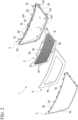
- FIG. 1 is a schematic front view of a vehicle 20 (mobile object) provided with a screen grille 1 (mobile-object-mounted display device) according to the first embodiment of the present invention.
- the vehicle 20 includes an openable and closable hood H disposed below a windshield G, headlamps L that are disposed below the hood H to be separated from each other to the left and right, and a front bumper B disposed below the headlamps L.
- hood H Surfaces of vehicle parts such as the hood H, the headlamps L, and the front bumper B have complicated three-dimensional shapes corresponding to a type of the vehicle 20 on which they are mounted.
- an upper surface of the hood H is curved to drop downward as it goes toward the front of the vehicle.
- the front surfaces of the headlamps L and the front surface of the front bumper B are curved rearward as they go toward ends of the vehicle 20 in a vehicle width direction.
- the screen grille 1 of the present embodiment is a display device that performs display of pictograms, characters, or the like toward the outside of the vehicle 20 (outside the mobile object), and as shown in FIG. 1 , it is disposed in a front part of the vehicle 20 to be surrounded by the vehicle parts having three-dimensional surfaces as described above.
- the screen grille 1 is disposed below the hood H, above the front bumper B, and between the left and right headlamps L.
- FIG. 2 is an exploded perspective view of the screen grille 1 of the present embodiment.
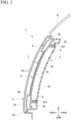
- FIG. 3 is a cross-sectional view of the screen grille 1 of the present embodiment along a vertical plane in a vehicle front-rear direction, and is a cross-sectional view along line A-A in FIG. 1 .
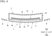
- FIG. 4 is a horizontal cross-sectional view of the screen grille 1 according to the present embodiment.
- the screen grille 1 of the present embodiment includes an inner member 2 (rear member), a display unit 3, a bezel 4, and an outer cover 5.
- a side where information is presented by the display unit 3 is called a front side
- a side where the information is not displayed by the display unit 3 is called a rear side.
- the inner member 2, the display unit 3, the bezel 4, and the outer cover 5 are arranged in a front-rear direction.
- the inner member 2 is disposed on a rearmost side
- the outer cover 5 is disposed on a foremost side.
- the inner member 2 is a member that directly or indirectly supports the display unit 3, the bezel 4, and the outer cover 5, and is disposed behind (to the rear of) the display unit 3, the bezel 4, and the outer cover 5.
- the inner member 2 is formed of a black ABS, for example.
- the inner member 2 has a plate-like portion 2a and an inner edge portion 2b provided to surround the plate-like portion 2a in an up-down direction and a left-right direction.
- the plate-like portion 2a is a plate-like portion that is disposed with a certain gap in the front-rear direction with respect to a support substrate 3a of the display unit 3, which will be described later, and covers the display unit 3 from behind.
- the plate-like portion 2a is curved in a cross-section in the front-rear direction of the vehicle such that the front surface thereof is closer to a vertical plane as it goes toward a front end.
- the front surface of the plate-like portion 2a is curved such that, near an upper end, a normal line to the front surface faces obliquely upward, and near a lower end, the normal line to the front surface is closer to the parallel than the normal line near the upper end.
- the plate-like portion 2a is curved in a horizontal cross-section such that the front surface thereof faces in the left-right direction as it goes toward the ends from a center of the vehicle 20.
- the front surface of the plate-like portion 2a is curved such that, near the left and right ends, the normal line to the front surface faces obliquely to the sides, and such that, near the center, the normal line to the front surface is closer to parallel to the front-rear direction than the normal line near the left and right ends.
- the plate-like portion 2a of the inner member 2 has a three-dimensional shape curved in the vertical and horizontal cross-sections.
- the plate-like portion 2a of the inner member 2 of which the front surface has a three-dimensional shape in this way is disposed with a certain gap with respect to the support substrate 3a (described later) of the display unit 3 which has a three-dimensional shape as well.
- the surface of the plate-like portion 2a of the inner member 2 does not necessarily have a three-dimensional shape, and may be flat.
- the plate-like portion 2a is provided with a plurality of holes 2a1 for fixing the display unit 3 with screws 6 (see FIG. 3 ).
- the display unit 3 is fixed to the inner member 2 by screwing the screws 6 inserted into the holes 2a1 into threaded portions 3b provided on the support substrate 3a of the display unit 3, which will be described later.
- the inner edge portion 2b of the inner member 2 is provided with a plurality of attachment portions 2c for attaching the inner member 2 to the vehicle body.
- the screen grille 1 of the present embodiment is fixed to the vehicle body by fixing these attachment portions 2c to the vehicle body with screws or the like (not shown).
- the inner edge portion 2b of the inner member 2 is provided with locking projections 2d for locking the outer cover 5.
- the outer cover 5 is coupled to the inner member 2 by the locking projections 2d.
- Such an inner member 2 is coupled to the outer cover 5 from behind and forms a closed space that accommodates LED elements 3d with the outer cover 5 therebetween.
- the display unit 3 is a device that displays characters and pictograms based on the control of a control device (not shown), and includes the support substrate 3a (light emitting element support body), the threaded portions 3b, a pasting sheet 3c (tape material), and the LED elements 3d (light emitting elements).
- “LED” means "light emitting diode.”
- the support substrate 3a is a plate-like portion to which the pasting sheet 3c is pasted on the front surface, and supports the LED elements 3d via the pasting sheet 3c.
- the support substrate 3a is curved in a cross-section in the front-rear direction of the vehicle such that the front surface thereof is closer to the vertical plane as it goes toward the front end.
- the front surface of the support substrate 3a is curved such that, near an upper end, a normal line to the front surface faces obliquely upward, and near a lower end, the normal line to the front surface is closer to parallel than the normal line near the upper end.
- the support substrate 3a is curved in a horizontal cross-section such that the front surface thereof faces in the left-right direction as it goes toward the ends from the center of the vehicle 20.
- the front surface of the support substrate 3a is curved such that, near the left and right ends, the normal line to the front surface faces obliquely to the sides, and such that, near the center, the normal line to the front surface is closer to parallel to the front-rear direction than the normal line near the left and right ends.
- the support substrate 3a has a three-dimensional shape curved in the vertical and horizontal cross-sections.
- the support substrate 3a of which the front surface has a three-dimensional shape in this way is disposed with a certain gap from the outer cover 5 which has a three-dimensional shape as well.
- Such a support substrate 3a supports a plurality of LED elements 3d such that the plurality of LED elements 3d are along the front surface of the support substrate 3a. That is, the LED elements 3d are arranged and supported by the support substrate 3a along the surface having the three-dimensional shape. That is, the support substrate 3a supports the plurality of LED elements 3d such that the plurality of LED elements 3d are disposed (arranged) along the front surface of the support substrate 3a. That is, the support substrate 3a supports the plurality of LED elements 3d such that the plurality of LED elements 3d are disposed (arranged) along the surface having the three-dimensional shape.
- the threaded portions 3b are cylindrical portions provided to protrude rearward from a back surface of the support substrate 3a and a plurality of threaded portions 3b are provided to correspond to the plurality of holes 2a1 provided in the plate-like portion 2a of the inner member 2. That is, the number of threaded portions 3b and the number of holes 2a1 are the same.
- the screws 6 are screwed into these threaded portions 3b, as shown in FIG. 3 .
- the pasting sheet 3c is a sheet material having the LED elements 3d fixed on the surface side and an adhesive surface on the back surface side.
- the pasting sheet 3c is pasted on the front surface of the support substrate 3a, and fixes the LED elements 3d with respect to the support substrate 3a.
- the LED elements 3d are fixed to the front surface of the support substrate 3a via the pasting sheet 3c, and the plurality of LED elements 3d are arranged in the front-rear direction and the left-right direction. These LED elements 3d are collectively disposed in a display area R (see FIG. 2 ) provided in the central portion of the support substrate 3a when viewed from the front. Each of the LED elements 3d is coupled to a lead wire (that is not shown) for supplying power to the LED elements 3d. These lead wires are extended laterally from the display area R, drawn out via openings provided in the support substrate 3a or the plate-like portion 2a of the inner member 2, for example, and coupled to the control device. Note that it is preferable to seal the openings for passing the lead wires. Desired characters or pictograms are displayed in the display area R by selectively causing these LED elements 3d to emit light.
- an area in which the LED elements 3d are not disposed is provided annularly around the display area R in the support substrate 3a, and the threaded portions 3b are provided on the back surface of the area where the LED elements 3d are not provided.
- the LED elements 3d are arranged along the front surface of the three-dimensional support substrate 3a. That is, the plurality of LED elements 3d are arranged along the surface having the three-dimensional shape. In the present embodiment, the LED elements 3d are arranged such that the LED elements 3d are along a curved surface that continues from the upper surface of the hood H in a cross-section in the front-rear direction of the vehicle. Further, in the present embodiment, the LED elements 3d are arranged such that the LED elements 3d are along the curved surface that continues from the front surface of the front bumper B in the horizontal cross-section.
- the plurality of LED elements 3d are arranged such that the LED elements 3d are along the three-dimensional curved surface that continues from the surfaces of the surrounding vehicle parts.
- the display surface has a three-dimensional shape instead of a planar shape.
- a buffer space K is provided between the LED elements 3d and the outer cover 5.
- the buffer space K is a space that prevents the LED elements 3d from coming into contact with the outer cover 5 even when the LED elements 3d and the outer cover 5 move relative to each other due to running vibrations of the vehicle 20. Further, by providing the buffer space K, it is possible to make it difficult to visually recognize the LED elements 3d from the front of the outer cover 5 when the LED elements 3d are turned off.
- the bezel 4 is an annular plate member having an opening 4a in the center, and has a frame shape surrounding the display area R when viewed from the outer cover 5 side.
- the bezel 4 is an interposing member interposed between the display unit 3 and the outer cover 5, and is formed of a black ABS, for example.
- the opening 4a of the bezel 4 has a shape slightly smaller than the display area R when viewed from the front side of the outer cover 5, such that the emitting LED elements 3d can be visually recognized from an outer side of the outer cover 5.
- the bezel 4 is disposed slightly ahead of the LED elements 3d, and is disposed with a slight gap from the LED elements 3d. As shown in FIG. 3 , the bezel 4 is disposed such that an inner edge portion slightly overlaps the LED element 3d arranged at the end of the display area R when viewed from the front. Since the inner edge portion forming the opening 4a of the bezel 4 slightly overlaps the LED element 3d at the end when viewed from the front, even when a gap is provided between the bezel 4 and the LED element 3d, it is possible to prevent the outer side of the display area R from being visually recognized from the outside. That is, it is possible to prevent the outer edge portion of the display area R from being visually recognized via the opening 4a of the bezel 4 when the opening 4a of the bezel 4 is viewed from the front side of the outer cover 5.
- such a bezel 4 functions as a stopper that restricts the display unit 3 from approaching the outer cover 5 due to running of the vehicle 20 or the like. Therefore, even when the vehicle 20 is stopped in an emergency, the bezel 4 can be prevented from approaching the outer cover 5 of the display unit 3, the LED element 3d can be prevented from coming into contact with the outer cover 5, and the distance between the LED elements 3d and the outer cover 5 can be prevented from changing.
- the outer cover 5 is a transparent cover member disposed in front of the display unit 3 (that is, the LED elements 3d).
- the outer cover 5 is formed of, for example, PMMA or the like.
- Such an outer cover 5 has a transparent plate-like portion 5a and an outer edge portion 5b provided to surround the transparent plate-like portion 5a in the up-down direction and the left-right direction.
- the front surface of the transparent plate-like portion 5a is curved such that, near an upper end, a normal line to the front surface faces obliquely upward, and near a lower end, the normal line to the front surface is closer to parallel than the normal line near the upper end.
- the transparent plate-like portion 5a is curved in a horizontal cross-section such that the rear surface thereof faces in the left-right direction as it goes toward the ends from the center of the vehicle 20. That is, the rear surface of the transparent plate-like portion 5a is curved such that, near the left and right ends, the normal lines to the rear surface and the front surface are inclined with respect to the front-rear direction, and near the center, the normal lines to the rear surface and the front surface are closer to parallel to the front-rear direction than the normal line near the left and right ends.
- the front and rear surfaces of the transparent plate-like portion 5a are three-dimensional surfaces curved with the same curvature such that the distance between the front and rear surfaces is always constant.
- the transparent plate-like portion 5a of the outer cover 5 has a three-dimensional shape curved in the vertical and horizontal cross-sections.
- the transparent plate-like portion 5a of the outer cover 5 having the three-dimensional front surface is disposed with a certain gap with respect to the LED elements 3d (that is, display area R) of the display unit 3, which is similarly formed into a three-dimensional shape.
- the outer edge portion 5b of the outer cover 5 is provided with locking claws 5c for locking the outer cover 5 to the inner member 2.
- the outer cover 5 is coupled to the inner member 2 by locking the locking claws 5c with the locking projections 2d of the inner member 2. Note that a boundary portion between the outer edge portion 5b and the inner edge portion 2b is sealed as necessary. Such sealing seals the closed space between the inner member 2 and the outer cover 5, making it possible to protect the LED elements 3d from moisture or the like in the air.
- characters or pictograms are displayed in the display area R by selectively causing the LED elements 3d to emit light.
- the LED elements 3d are arranged and supported along the three-dimensional surface along the upper surface of the hood H and the front surface of the front bumper B, the characters or pictograms displayed in the display area R are similarly displayed along the three-dimensional surface. Therefore, it is possible to prevent the displayed characters or pictograms from becoming flat, and to enhance the unity of the characters or pictograms with the surfaces of surrounding three-dimensional vehicle parts.
- the screen grille 1 of the present embodiment as described above is mounted on the vehicle 20 and performs display toward the outside of the vehicle 20.
- the screen grille 1 of the present embodiment includes a plurality of LED elements 3d and a support substrate 3a for arranging and supporting the plurality of LED elements 3d along the surface having the three-dimensional shape.
- a plurality of LED elements 3d are provided, and these LED elements 3d are arranged and supported by the support substrate 3a along the surface having the three-dimensional shape. Therefore, the display surface formed by the plurality of LED elements 3d has a three-dimensional shape instead of a planar shape. Therefore, according to the screen grille 1 of the present embodiment, by installing the planar display unit 3 on the surface of the vehicle 20 having a three-dimensional shape, it is possible to reduce the sense of discomfort from the appearance felt by a person outside the vehicle. Therefore, according to the screen grille 1 of the present embodiment, in the screen grille 1 that is mounted on the vehicle 20 and performs display toward the outside of the vehicle, it is possible to improve unity with surrounding parts.
- the support substrate 3a has a curved surface along the surface having the three-dimensional shape and to which the pasting sheet 3c having the LED elements 3d attached is pasted. Therefore, by attaching the LED elements 3d to the surface of the support substrate 3a, it becomes possible to easily arrange and support the LED elements 3d along the surface having the three-dimensional shape.
- the screen grille 1 of the present embodiment is provided with the outer cover 5 that is disposed in front of the LED elements 3d and has translucency, and a buffer space K is provided between the LED elements 3d and the outer cover 5. Therefore, even when the LED elements 3d and the outer cover 5 move relative to each other due to running vibrations of the vehicle 20 or the like, the LED elements 3d can be prevented from coming into contact with the outer cover 5. Further, by providing the buffer space K, it is possible to make it difficult to visually recognize the LED elements 3d from the front of the outer cover 5 when the LED elements 3d are turned off.
- the screen grille 1 of the present embodiment includes a bezel 4 interposed between the support substrate 3a and the outer cover 5, and the bezel 4 is disposed to avoid at least a part of the display area R where the plurality of LED elements 3d are disposed when viewed from the outer cover 5 side.
- a bezel 4 functions as a stopper that restricts the display unit 3 from approaching the outer cover 5 due to running of the vehicle 20 or the like. Therefore, even when the vehicle 20 is stopped in an emergency, the bezel 4 can be prevented from approaching the outer cover 5 of the display unit 3, the LED element 3d can be prevented from coming into contact with the outer cover 5, and the distance between the LED elements 3d and the outer cover 5 can be prevented from changing.
- the bezel 4 has a frame shape surrounding the display area R when viewed from the outer cover 5 side. Therefore, the bezel 4 can hide the up-down direction and the left-right direction of the area where the LED elements 3d are disposed, and the lead wires and the like coupled to the LED elements 3d can be hidden. That is, the bezel 4 can hide the outer edge portions of the area where the LED elements 3d are disposed extending in the up-down direction and left-right direction, and the lead wires and the like coupled to the LED elements 3d can be hidden. Therefore, the screen grille 1 of the present embodiment can improve the external impression of the screen grille 1 by including the bezel 4.
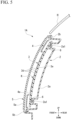
- FIG. 5 is a cross-sectional view of a screen grille 1A of the present embodiment along a vertical plane in the front-rear direction of the vehicle.
- the display unit 3 does not include the support substrate 3a or the pasting sheet 3c, but includes a circuit board 3e (light emitting element support body).
- the circuit board 3e is a wiring board on which the LED elements 3d are mounted on the front side, and supports the mounted LED elements 3d. As shown in FIG. 5 , the circuit board 3e is curved in a cross-section in the front-rear direction of the vehicle such that the front surface thereof is closer to the vertical plane as it goes toward the rear end. In other words, the front surface of the circuit board 3e is curved such that, near an upper end, a normal line to the front surface faces obliquely upward, and near a lower end, the normal line to the front surface is closer to parallel than the normal line near the upper end.
- FIG. 6 is a horizontal cross-sectional view of the screen grille 1A of the present embodiment.
- the circuit board 3e is curved in a horizontal cross-section such that the front surface thereof faces in the left-right direction as it goes toward the ends from the center of the vehicle 20.
- the front surface of the circuit board 3e is curved such that, near the left and right ends, the normal line to the front surface faces obliquely to the sides, and near the center, the normal line to the front surface is closer to parallel to the front-rear direction than the normal line near the left and right ends.
- the circuit board 3e has a three-dimensional shape curved in the vertical and horizontal cross-sections.
- the circuit board 3e of which the front surface has a three-dimensional shape in this way is disposed with a certain gap from the outer cover 5 which has a three-dimensional shape as well.
- Such a circuit board 3e supports a plurality of LED elements 3d such that the LED elements 3d are along the front surface of the circuit board 3e. That is, the LED elements 3d are arranged and supported by the support substrate 3a along the surface having the three-dimensional shape.
- the circuit board 3e has a three-dimensional front surface on which the LED elements 3d are mounted. Therefore, by mounting the LED elements 3d on the surface of the circuit board 3e, it becomes possible to easily arrange and support the LED elements 3d along the surface having the three-dimensional shape.
- the LED elements 3d can be energized through the circuit board 3e, and the lead wires coupled to each of the LED elements 3d do not have to be drawn out to the outside of the screen grille 1A. That is, except for the lead wires for energizing the main body of the circuit board 3e and signal wires for sending signals, there are no wires drawn out of the screen grille 1A, and the wires drawn out of the screen grille 1A can be greatly reduced.
- a control chip on the circuit board 3e, it becomes possible to perform lighting control of each of the LED elements 3d by the control chip mounted on the circuit board 3e.
- the configuration including the LED elements 3d as the light emitting elements has been described.
- the present invention is not limited to this.
- the light emitting elements it is possible to use a single surface emitting organic EL (electroluminescence) element or the like having a three-dimensional shape. In this case, the light emitting elements can be configured with a simple configuration.
- the configuration in which the LED elements 3d are arranged and supported along the curved surface has been described.
- the present invention is not limited to this.
- the bezel 4 may be bilaterally symmetrical to overlap at least one of the upper edge portion, lower edge portion, left edge portion, and right edge portion of the display area R.
- the shape of the bezel 4 may be a shape that overlaps only the upper edge portion, a shape that overlaps only the lower edge portion, a shape that overlaps only the left and right sides, and a shape that overlaps either the upper edge portion or the lower edge portion and both the left and right sides.
- the bezel 4 functions as a stopper that restricts the display unit 3 from approaching the outer cover 5.
- the bezel 4 can prevent the outer side of the display area R from being visually recognized from the outside.
- the bezel 4 functions as the stopper when the bezel 4 overlaps at least one of the upper edge portion, the lower edge portion, the left edge portion, and the right edge portion of the display area R, it is preferable that the bezel 4 be bilaterally symmetrical when viewed from the front of the vehicle in terms of aesthetics of the vehicle.
- the present invention is not limited to this.
- the mobile object on which the mobile-object-mounted device of the present invention is mounted is the vehicle 20.
- the present invention is not limited to this.
- the configuration including the outer cover 5 has been described.
- the present invention is not limited to this.
- the light emitting element has weather resistance, it is possible to adopt a configuration without the outer cover 5.
- one or a plurality of light emitting elements are provided, and these light emitting elements are supported along a surface having a three-dimensional shape by the light emitting element support body.
- a display surface formed by the one or plurality of light emitting elements is not planar but has a three-dimensional shape. Therefore, according to the present invention, by installing a planar display unit on the surface of a three-dimensional mobile object, it is possible to reduce the sense of discomfort from the appearance felt by a person outside the mobile object. Therefore, according to the present invention, it is possible to improve unity with the surroundings of a mobile-object-mounted display device that is mounted on a mobile object and performs display toward the outside of the mobile object.
Landscapes
- Engineering & Computer Science (AREA)
- General Engineering & Computer Science (AREA)
- Physics & Mathematics (AREA)
- Mechanical Engineering (AREA)
- General Physics & Mathematics (AREA)
- Theoretical Computer Science (AREA)
- Optics & Photonics (AREA)
- Microelectronics & Electronic Packaging (AREA)
- Chemical & Material Sciences (AREA)
- Combustion & Propulsion (AREA)
- Transportation (AREA)
- Business, Economics & Management (AREA)
- Accounting & Taxation (AREA)
- Marketing (AREA)
- Illuminated Signs And Luminous Advertising (AREA)
- Fittings On The Vehicle Exterior For Carrying Loads, And Devices For Holding Or Mounting Articles (AREA)
- Fastening Of Light Sources Or Lamp Holders (AREA)
Abstract
Description
- The present invention relates to a mobile-object-mounted display device. Priority is claimed on
Japanese Patent Application No. 2020-140030, filed August 21, 2020 - In recent years, it has been proposed to install a display device that displays information to pedestrians and other drivers outside a vehicle on the vehicle or the like, assuming the spread or the like of autonomous vehicles in the future. For example, Patent Document 1 proposes a driving support system provided with an own vehicle external display device.
- [Patent Document 1]
Japanese Patent No. 6680136 - However, general displays display information on a flat display surface. On the other hand, an outer surface of a vehicle is generally made into a three-dimensional shape in order to improve an external impression of the vehicle or the like. When a display device such as a planar display is installed on the outer surface of a vehicle made into a three-dimensional shape, especially when information is displayed on the display device, the display loses its unity with surroundings. Therefore, a possibility that an appearance of a mobile object such as a vehicle gives a sense of discomfort to a person outside the vehicle increases.
- The present invention has been made in view of the above-described problems, and an object of the present invention is to improve unity with the surroundings in a mobile-object-mounted display device that is mounted on a mobile object and performs display toward an outside of the mobile object.
- The present invention adopts the following aspects as means for solving the above problems.
- A first aspect is a mobile-object-mounted display device that is mounted on a mobile object and performs display toward an outside of the mobile object, the device including: one or a plurality of light emitting elements; and a light emitting element support body that supports the one or the plurality of light emitting elements along a surface having a three-dimensional shape.
- A second aspect is the mobile-object-mounted display device according to the first aspect, in which the plurality of the light emitting elements are provided, and the plurality of light emitting elements are arranged along the surface having the three-dimensional shape.
- A third aspect is the mobile-object-mounted display device according to the second aspect, in which the light emitting element support body is a circuit board on which the light emitting elements are mounted and which has a curved surface along the surface having the three-dimensional shape.
- A fourth aspect is the mobile-object-mounted display device according to the second aspect, in which the light emitting element support body is a support substrate to which a tape material to which the light emitting elements are attached is pasted and which has a curved surface along the surface having the three-dimensional shape.
- A fifth aspect is the mobile-object-mounted display device according to the first aspect, in which one organic EL element is provided as the light emitting element.
- A sixth aspect is the mobile-object-mounted display device according to any one of the first to fifth aspects, further including an outer cover that is disposed in front of the light emitting elements and has translucency, in which a buffer space is provided between the light emitting elements and the outer cover.
- A seventh aspect is the mobile-object-mounted display device according to the sixth aspect, further including an interposing member interposed between the light emitting element support body and the outer cover, in which the interposing member is disposed to avoid at least a part of a display area in which the plurality of light emitting elements are disposed when viewed from an outer cover side.
- An eighth aspect is the mobile-object-mounted display device according to the seventh aspect, in which the display area has a rectangular shape having an upper edge portion, a lower edge portion, a left edge portion, and a right edge portion when viewed from the outer cover side, and the interposing member has a bilaterally symmetrical shape that overlaps at least any one of the upper edge portion, the lower edge portion, the left edge portion, and the right edge portion of the display area when viewed from the outer cover side.
- A ninth aspect is the mobile-object-mounted display device according to the eighth aspect, in which the interposing member has a frame shape surrounding the display area when viewed from the outer cover side.
- A tenth aspect is the mobile-object-mounted display device according to any one of the sixth to ninth aspects, further including a rear member that is coupled to the outer cover from behind and forms a closed space that accommodates the light emitting elements with the outer cover therebetween.
- According to the present invention, one or a plurality of light emitting elements are provided, and these light emitting elements are supported along a surface having a three-dimensional shape by the light emitting element support body. For this reason, a display surface formed by the one or a plurality of light emitting elements is not planar but has a three-dimensional shape. Therefore, according to the present invention, by installing a planar display unit on a surface of a three-dimensional mobile object, it is possible to reduce the sense of discomfort from the appearance felt by a person outside the mobile object. Therefore, according to the present invention, it is possible to improve unity with the surroundings of a mobile-object-mounted display device that is mounted on the mobile object and performs display toward an outside of the mobile object.
-
-
FIG. 1 is a schematic front view of a vehicle provided with a screen grille according to a first embodiment of the present invention. -
FIG. 2 is an exploded perspective view of the screen grille according to the first embodiment of the present invention. -
FIG. 3 is a cross-sectional view of the screen grille according to the first embodiment of the present invention along a vertical plane in a vehicle front-rear direction. -
FIG. 4 is a horizontal cross-sectional view of the screen grille according to the first embodiment of the present invention. -
FIG. 5 is a cross-sectional view of a screen grille according to a second embodiment of the present invention along a vertical plane in the vehicle front-rear direction. -
FIG. 6 is a horizontal cross-sectional view of the screen grille according to the second embodiment of the present invention. - An embodiment of a mobile-object-mounted display device according to the present invention will be described below with reference to the drawings.
-
FIG. 1 is a schematic front view of a vehicle 20 (mobile object) provided with a screen grille 1 (mobile-object-mounted display device) according to the first embodiment of the present invention. As shown inFIG. 1 , thevehicle 20 includes an openable and closable hood H disposed below a windshield G, headlamps L that are disposed below the hood H to be separated from each other to the left and right, and a front bumper B disposed below the headlamps L. - Surfaces of vehicle parts such as the hood H, the headlamps L, and the front bumper B have complicated three-dimensional shapes corresponding to a type of the
vehicle 20 on which they are mounted. For example, in the present embodiment, an upper surface of the hood H is curved to drop downward as it goes toward the front of the vehicle. The front surfaces of the headlamps L and the front surface of the front bumper B are curved rearward as they go toward ends of thevehicle 20 in a vehicle width direction. - Note that the vehicle parts mounted on the
vehicle 20 in the present embodiment are only examples, and other vehicle parts can be mounted on thevehicle 20. Further, the surface shapes of the vehicle parts according to the present embodiment are also examples, and the surface shapes of the vehicle parts can be changed to a three-dimensional shape instead of a flat surface. However, not all vehicle parts need to have a three-dimensional surface shape. At least one surface shape of the plurality of vehicle parts has a three-dimensional shape. - The screen grille 1 of the present embodiment is a display device that performs display of pictograms, characters, or the like toward the outside of the vehicle 20 (outside the mobile object), and as shown in
FIG. 1 , it is disposed in a front part of thevehicle 20 to be surrounded by the vehicle parts having three-dimensional surfaces as described above. In the present embodiment, the screen grille 1 is disposed below the hood H, above the front bumper B, and between the left and right headlamps L. -
FIG. 2 is an exploded perspective view of the screen grille 1 of the present embodiment.FIG. 3 is a cross-sectional view of the screen grille 1 of the present embodiment along a vertical plane in a vehicle front-rear direction, and is a cross-sectional view along line A-A inFIG. 1 .FIG. 4 is a horizontal cross-sectional view of the screen grille 1 according to the present embodiment. For example, as shown inFIGS. 2 and3 , the screen grille 1 of the present embodiment includes an inner member 2 (rear member), adisplay unit 3, abezel 4, and anouter cover 5. - Note that, in the following description, a side where information is presented by the
display unit 3 is called a front side, and a side where the information is not displayed by thedisplay unit 3 is called a rear side. In the present embodiment, theinner member 2, thedisplay unit 3, thebezel 4, and theouter cover 5 are arranged in a front-rear direction. Among these, theinner member 2 is disposed on a rearmost side, and theouter cover 5 is disposed on a foremost side. - The
inner member 2 is a member that directly or indirectly supports thedisplay unit 3, thebezel 4, and theouter cover 5, and is disposed behind (to the rear of) thedisplay unit 3, thebezel 4, and theouter cover 5. Theinner member 2 is formed of a black ABS, for example. Theinner member 2 has a plate-like portion 2a and aninner edge portion 2b provided to surround the plate-like portion 2a in an up-down direction and a left-right direction. - The plate-
like portion 2a is a plate-like portion that is disposed with a certain gap in the front-rear direction with respect to asupport substrate 3a of thedisplay unit 3, which will be described later, and covers thedisplay unit 3 from behind. As shown inFIG. 3 , the plate-like portion 2a is curved in a cross-section in the front-rear direction of the vehicle such that the front surface thereof is closer to a vertical plane as it goes toward a front end. In other words, the front surface of the plate-like portion 2a is curved such that, near an upper end, a normal line to the front surface faces obliquely upward, and near a lower end, the normal line to the front surface is closer to the parallel than the normal line near the upper end. - Further, as shown in
FIG. 4 , the plate-like portion 2a is curved in a horizontal cross-section such that the front surface thereof faces in the left-right direction as it goes toward the ends from a center of thevehicle 20. In other words, the front surface of the plate-like portion 2a is curved such that, near the left and right ends, the normal line to the front surface faces obliquely to the sides, and such that, near the center, the normal line to the front surface is closer to parallel to the front-rear direction than the normal line near the left and right ends. - Thus, in the present embodiment, the plate-
like portion 2a of theinner member 2 has a three-dimensional shape curved in the vertical and horizontal cross-sections. The plate-like portion 2a of theinner member 2 of which the front surface has a three-dimensional shape in this way is disposed with a certain gap with respect to thesupport substrate 3a (described later) of thedisplay unit 3 which has a three-dimensional shape as well. Note that the surface of the plate-like portion 2a of theinner member 2 does not necessarily have a three-dimensional shape, and may be flat. - Further, the plate-
like portion 2a is provided with a plurality of holes 2a1 for fixing thedisplay unit 3 with screws 6 (seeFIG. 3 ). Thedisplay unit 3 is fixed to theinner member 2 by screwing thescrews 6 inserted into the holes 2a1 into threadedportions 3b provided on thesupport substrate 3a of thedisplay unit 3, which will be described later. Further, theinner edge portion 2b of theinner member 2 is provided with a plurality ofattachment portions 2c for attaching theinner member 2 to the vehicle body. The screen grille 1 of the present embodiment is fixed to the vehicle body by fixing theseattachment portions 2c to the vehicle body with screws or the like (not shown). - The
inner edge portion 2b of theinner member 2 is provided with lockingprojections 2d for locking theouter cover 5. Theouter cover 5 is coupled to theinner member 2 by the lockingprojections 2d. Such aninner member 2 is coupled to theouter cover 5 from behind and forms a closed space that accommodatesLED elements 3d with theouter cover 5 therebetween. - The
display unit 3 is a device that displays characters and pictograms based on the control of a control device (not shown), and includes thesupport substrate 3a (light emitting element support body), the threadedportions 3b, apasting sheet 3c (tape material), and theLED elements 3d (light emitting elements). "LED" means "light emitting diode." - The
support substrate 3a is a plate-like portion to which thepasting sheet 3c is pasted on the front surface, and supports theLED elements 3d via thepasting sheet 3c. As shown inFIG. 3 , thesupport substrate 3a is curved in a cross-section in the front-rear direction of the vehicle such that the front surface thereof is closer to the vertical plane as it goes toward the front end. In other words, the front surface of thesupport substrate 3a is curved such that, near an upper end, a normal line to the front surface faces obliquely upward, and near a lower end, the normal line to the front surface is closer to parallel than the normal line near the upper end. - Further, as shown in
FIG. 4 , thesupport substrate 3a is curved in a horizontal cross-section such that the front surface thereof faces in the left-right direction as it goes toward the ends from the center of thevehicle 20. In other words, the front surface of thesupport substrate 3a is curved such that, near the left and right ends, the normal line to the front surface faces obliquely to the sides, and such that, near the center, the normal line to the front surface is closer to parallel to the front-rear direction than the normal line near the left and right ends. - Thus, in the present embodiment, the
support substrate 3a has a three-dimensional shape curved in the vertical and horizontal cross-sections. Thesupport substrate 3a of which the front surface has a three-dimensional shape in this way is disposed with a certain gap from theouter cover 5 which has a three-dimensional shape as well. Such asupport substrate 3a supports a plurality ofLED elements 3d such that the plurality ofLED elements 3d are along the front surface of thesupport substrate 3a. That is, theLED elements 3d are arranged and supported by thesupport substrate 3a along the surface having the three-dimensional shape. That is, thesupport substrate 3a supports the plurality ofLED elements 3d such that the plurality ofLED elements 3d are disposed (arranged) along the front surface of thesupport substrate 3a. That is, thesupport substrate 3a supports the plurality ofLED elements 3d such that the plurality ofLED elements 3d are disposed (arranged) along the surface having the three-dimensional shape. - The threaded
portions 3b are cylindrical portions provided to protrude rearward from a back surface of thesupport substrate 3a and a plurality of threadedportions 3b are provided to correspond to the plurality of holes 2a1 provided in the plate-like portion 2a of theinner member 2. That is, the number of threadedportions 3b and the number of holes 2a1 are the same. Thescrews 6 are screwed into these threadedportions 3b, as shown inFIG. 3 . - The
pasting sheet 3c is a sheet material having theLED elements 3d fixed on the surface side and an adhesive surface on the back surface side. Thepasting sheet 3c is pasted on the front surface of thesupport substrate 3a, and fixes theLED elements 3d with respect to thesupport substrate 3a. - The
LED elements 3d are fixed to the front surface of thesupport substrate 3a via thepasting sheet 3c, and the plurality ofLED elements 3d are arranged in the front-rear direction and the left-right direction. TheseLED elements 3d are collectively disposed in a display area R (seeFIG. 2 ) provided in the central portion of thesupport substrate 3a when viewed from the front. Each of theLED elements 3d is coupled to a lead wire (that is not shown) for supplying power to theLED elements 3d. These lead wires are extended laterally from the display area R, drawn out via openings provided in thesupport substrate 3a or the plate-like portion 2a of theinner member 2, for example, and coupled to the control device. Note that it is preferable to seal the openings for passing the lead wires. Desired characters or pictograms are displayed in the display area R by selectively causing theseLED elements 3d to emit light. - In addition, as shown in
FIG. 2 , an area in which theLED elements 3d are not disposed is provided annularly around the display area R in thesupport substrate 3a, and the threadedportions 3b are provided on the back surface of the area where theLED elements 3d are not provided. - Here, the
LED elements 3d are arranged along the front surface of the three-dimensional support substrate 3a. That is, the plurality ofLED elements 3d are arranged along the surface having the three-dimensional shape. In the present embodiment, theLED elements 3d are arranged such that theLED elements 3d are along a curved surface that continues from the upper surface of the hood H in a cross-section in the front-rear direction of the vehicle. Further, in the present embodiment, theLED elements 3d are arranged such that theLED elements 3d are along the curved surface that continues from the front surface of the front bumper B in the horizontal cross-section. Thus, in the present embodiment, the plurality ofLED elements 3d are arranged such that theLED elements 3d are along the three-dimensional curved surface that continues from the surfaces of the surrounding vehicle parts. As a result, the display surface has a three-dimensional shape instead of a planar shape. - Further, a buffer space K is provided between the
LED elements 3d and theouter cover 5. The buffer space K is a space that prevents theLED elements 3d from coming into contact with theouter cover 5 even when theLED elements 3d and theouter cover 5 move relative to each other due to running vibrations of thevehicle 20. Further, by providing the buffer space K, it is possible to make it difficult to visually recognize theLED elements 3d from the front of theouter cover 5 when theLED elements 3d are turned off. - As shown in
FIG. 2 , thebezel 4 is an annular plate member having anopening 4a in the center, and has a frame shape surrounding the display area R when viewed from theouter cover 5 side. Thebezel 4 is an interposing member interposed between thedisplay unit 3 and theouter cover 5, and is formed of a black ABS, for example. Theopening 4a of thebezel 4 has a shape slightly smaller than the display area R when viewed from the front side of theouter cover 5, such that the emittingLED elements 3d can be visually recognized from an outer side of theouter cover 5. - The
bezel 4 is disposed slightly ahead of theLED elements 3d, and is disposed with a slight gap from theLED elements 3d. As shown inFIG. 3 , thebezel 4 is disposed such that an inner edge portion slightly overlaps theLED element 3d arranged at the end of the display area R when viewed from the front. Since the inner edge portion forming theopening 4a of thebezel 4 slightly overlaps theLED element 3d at the end when viewed from the front, even when a gap is provided between thebezel 4 and theLED element 3d, it is possible to prevent the outer side of the display area R from being visually recognized from the outside. That is, it is possible to prevent the outer edge portion of the display area R from being visually recognized via theopening 4a of thebezel 4 when theopening 4a of thebezel 4 is viewed from the front side of theouter cover 5. - Further, such a
bezel 4 functions as a stopper that restricts thedisplay unit 3 from approaching theouter cover 5 due to running of thevehicle 20 or the like. Therefore, even when thevehicle 20 is stopped in an emergency, thebezel 4 can be prevented from approaching theouter cover 5 of thedisplay unit 3, theLED element 3d can be prevented from coming into contact with theouter cover 5, and the distance between theLED elements 3d and theouter cover 5 can be prevented from changing. - The
outer cover 5 is a transparent cover member disposed in front of the display unit 3 (that is, theLED elements 3d). Theouter cover 5 is formed of, for example, PMMA or the like. Such anouter cover 5 has a transparent plate-like portion 5a and anouter edge portion 5b provided to surround the transparent plate-like portion 5a in the up-down direction and the left-right direction. - The transparent plate-
like portion 5a is a plate-like portion that is disposed in front of theLED elements 3d and covers thedisplay unit 3 from the front. As shown inFIG. 3 , the transparent plate-like portion 5a is curved in a cross-section in the vehicle front-rear direction such that the rear surface thereof is closer to the vertical plane as it goes toward the front end. In other words, the inner surface of the transparent plate-like portion 5a is curved such that, near an upper end, a normal line to the rear surface faces obliquely downward, and near the lower end, the normal line to the rear surface is closer to parallel than the normal line near the upper end. Further, the front surface of the transparent plate-like portion 5a is curved such that, near an upper end, a normal line to the front surface faces obliquely upward, and near a lower end, the normal line to the front surface is closer to parallel than the normal line near the upper end. - Further, as shown in
FIG. 4 , the transparent plate-like portion 5a is curved in a horizontal cross-section such that the rear surface thereof faces in the left-right direction as it goes toward the ends from the center of thevehicle 20. That is, the rear surface of the transparent plate-like portion 5a is curved such that, near the left and right ends, the normal lines to the rear surface and the front surface are inclined with respect to the front-rear direction, and near the center, the normal lines to the rear surface and the front surface are closer to parallel to the front-rear direction than the normal line near the left and right ends. - In the present embodiment, the front and rear surfaces of the transparent plate-
like portion 5a are three-dimensional surfaces curved with the same curvature such that the distance between the front and rear surfaces is always constant. Thus, in the present embodiment, the transparent plate-like portion 5a of theouter cover 5 has a three-dimensional shape curved in the vertical and horizontal cross-sections. - The transparent plate-
like portion 5a of theouter cover 5 having the three-dimensional front surface is disposed with a certain gap with respect to theLED elements 3d (that is, display area R) of thedisplay unit 3, which is similarly formed into a three-dimensional shape. - The
outer edge portion 5b of theouter cover 5 is provided with lockingclaws 5c for locking theouter cover 5 to theinner member 2. Theouter cover 5 is coupled to theinner member 2 by locking the lockingclaws 5c with the lockingprojections 2d of theinner member 2. Note that a boundary portion between theouter edge portion 5b and theinner edge portion 2b is sealed as necessary. Such sealing seals the closed space between theinner member 2 and theouter cover 5, making it possible to protect theLED elements 3d from moisture or the like in the air. - In the screen grille 1 of the present embodiment, characters or pictograms are displayed in the display area R by selectively causing the
LED elements 3d to emit light. At this time, in the screen grille 1 of the present embodiment, since theLED elements 3d are arranged and supported along the three-dimensional surface along the upper surface of the hood H and the front surface of the front bumper B, the characters or pictograms displayed in the display area R are similarly displayed along the three-dimensional surface. Therefore, it is possible to prevent the displayed characters or pictograms from becoming flat, and to enhance the unity of the characters or pictograms with the surfaces of surrounding three-dimensional vehicle parts. - The screen grille 1 of the present embodiment as described above is mounted on the
vehicle 20 and performs display toward the outside of thevehicle 20. The screen grille 1 of the present embodiment includes a plurality ofLED elements 3d and asupport substrate 3a for arranging and supporting the plurality ofLED elements 3d along the surface having the three-dimensional shape. - According to the screen grille 1 of the present embodiment, a plurality of
LED elements 3d are provided, and theseLED elements 3d are arranged and supported by thesupport substrate 3a along the surface having the three-dimensional shape. Therefore, the display surface formed by the plurality ofLED elements 3d has a three-dimensional shape instead of a planar shape. Therefore, according to the screen grille 1 of the present embodiment, by installing theplanar display unit 3 on the surface of thevehicle 20 having a three-dimensional shape, it is possible to reduce the sense of discomfort from the appearance felt by a person outside the vehicle. Therefore, according to the screen grille 1 of the present embodiment, in the screen grille 1 that is mounted on thevehicle 20 and performs display toward the outside of the vehicle, it is possible to improve unity with surrounding parts. - In the screen grille 1 of the present embodiment, the
support substrate 3a has a curved surface along the surface having the three-dimensional shape and to which thepasting sheet 3c having theLED elements 3d attached is pasted. Therefore, by attaching theLED elements 3d to the surface of thesupport substrate 3a, it becomes possible to easily arrange and support theLED elements 3d along the surface having the three-dimensional shape. - Further, the screen grille 1 of the present embodiment is provided with the
outer cover 5 that is disposed in front of theLED elements 3d and has translucency, and a buffer space K is provided between theLED elements 3d and theouter cover 5. Therefore, even when theLED elements 3d and theouter cover 5 move relative to each other due to running vibrations of thevehicle 20 or the like, theLED elements 3d can be prevented from coming into contact with theouter cover 5. Further, by providing the buffer space K, it is possible to make it difficult to visually recognize theLED elements 3d from the front of theouter cover 5 when theLED elements 3d are turned off. - Further, the screen grille 1 of the present embodiment includes a
bezel 4 interposed between thesupport substrate 3a and theouter cover 5, and thebezel 4 is disposed to avoid at least a part of the display area R where the plurality ofLED elements 3d are disposed when viewed from theouter cover 5 side. Such abezel 4 functions as a stopper that restricts thedisplay unit 3 from approaching theouter cover 5 due to running of thevehicle 20 or the like. Therefore, even when thevehicle 20 is stopped in an emergency, thebezel 4 can be prevented from approaching theouter cover 5 of thedisplay unit 3, theLED element 3d can be prevented from coming into contact with theouter cover 5, and the distance between theLED elements 3d and theouter cover 5 can be prevented from changing. - Further, in the screen grille 1 of the present embodiment, the
bezel 4 has a frame shape surrounding the display area R when viewed from theouter cover 5 side. Therefore, thebezel 4 can hide the up-down direction and the left-right direction of the area where theLED elements 3d are disposed, and the lead wires and the like coupled to theLED elements 3d can be hidden. That is, thebezel 4 can hide the outer edge portions of the area where theLED elements 3d are disposed extending in the up-down direction and left-right direction, and the lead wires and the like coupled to theLED elements 3d can be hidden. Therefore, the screen grille 1 of the present embodiment can improve the external impression of the screen grille 1 by including thebezel 4. - Further, the screen grille 1 of the present embodiment includes an
inner member 2 that is coupled to theouter cover 5 from behind and forms a closed space that accommodates theLED elements 3d with theouter cover 5 therebetween. Therefore, it is possible to prevent external moisture or the like from entering the space between theinner member 2 and theouter cover 5, thereby protecting theLED elements 3d from moisture or the like. - Next, a second embodiment of the present invention will be described. Note that, in the description of the present embodiment, the description of the same parts as those of the first embodiment will be omitted or simplified.
-
FIG. 5 is a cross-sectional view of ascreen grille 1A of the present embodiment along a vertical plane in the front-rear direction of the vehicle. As shown in this figure, in thescreen grille 1A of the present embodiment, thedisplay unit 3 does not include thesupport substrate 3a or thepasting sheet 3c, but includes acircuit board 3e (light emitting element support body). - The
circuit board 3e is a wiring board on which theLED elements 3d are mounted on the front side, and supports the mountedLED elements 3d. As shown inFIG. 5 , thecircuit board 3e is curved in a cross-section in the front-rear direction of the vehicle such that the front surface thereof is closer to the vertical plane as it goes toward the rear end. In other words, the front surface of thecircuit board 3e is curved such that, near an upper end, a normal line to the front surface faces obliquely upward, and near a lower end, the normal line to the front surface is closer to parallel than the normal line near the upper end. -
FIG. 6 is a horizontal cross-sectional view of thescreen grille 1A of the present embodiment. As shown in this figure, thecircuit board 3e is curved in a horizontal cross-section such that the front surface thereof faces in the left-right direction as it goes toward the ends from the center of thevehicle 20. In other words, the front surface of thecircuit board 3e is curved such that, near the left and right ends, the normal line to the front surface faces obliquely to the sides, and near the center, the normal line to the front surface is closer to parallel to the front-rear direction than the normal line near the left and right ends. - Thus, in the present embodiment, the
circuit board 3e has a three-dimensional shape curved in the vertical and horizontal cross-sections. Thecircuit board 3e of which the front surface has a three-dimensional shape in this way is disposed with a certain gap from theouter cover 5 which has a three-dimensional shape as well. Such acircuit board 3e supports a plurality ofLED elements 3d such that theLED elements 3d are along the front surface of thecircuit board 3e. That is, theLED elements 3d are arranged and supported by thesupport substrate 3a along the surface having the three-dimensional shape. - In the
screen grille 1A of the present embodiment as described above, thecircuit board 3e has a three-dimensional front surface on which theLED elements 3d are mounted. Therefore, by mounting theLED elements 3d on the surface of thecircuit board 3e, it becomes possible to easily arrange and support theLED elements 3d along the surface having the three-dimensional shape. - Moreover, by mounting the
LED elements 3d on thecircuit board 3e, theLED elements 3d can be energized through thecircuit board 3e, and the lead wires coupled to each of theLED elements 3d do not have to be drawn out to the outside of thescreen grille 1A. That is, except for the lead wires for energizing the main body of thecircuit board 3e and signal wires for sending signals, there are no wires drawn out of thescreen grille 1A, and the wires drawn out of thescreen grille 1A can be greatly reduced. Moreover, by mounting a control chip on thecircuit board 3e, it becomes possible to perform lighting control of each of theLED elements 3d by the control chip mounted on thecircuit board 3e. - Although the preferred embodiments of the present invention have been described above with reference to the accompanying drawings, it goes without saying that the present invention is not limited to the above embodiments. The various shapes, combinations, and the like of each of the constituent members shown in the above-described embodiment are merely examples, and can be variously changed based on design requirements and the like without departing from the gist of the present invention.
- For example, in the above-described embodiment, the configuration including the
LED elements 3d as the light emitting elements has been described. However, the present invention is not limited to this. For example, as the light emitting elements, it is possible to use a single surface emitting organic EL (electroluminescence) element or the like having a three-dimensional shape. In this case, the light emitting elements can be configured with a simple configuration. - Moreover, in the above embodiment, the configuration in which the
LED elements 3d are arranged and supported along the curved surface has been described. However, the present invention is not limited to this. For example, it is possible to adopt a configuration in which the light emitting elements are arranged and supported along a three-dimensional surface provided with a stepped portion and a curved portion. - Further, in the above-described embodiment, the configuration in which the
bezel 4 is an annular plate member has been described. However, the present invention is not limited to this. When viewed from the front of the vehicle, thebezel 4 may be bilaterally symmetrical to overlap at least one of the upper edge portion, lower edge portion, left edge portion, and right edge portion of the display area R. For example, the shape of thebezel 4 may be a shape that overlaps only the upper edge portion, a shape that overlaps only the lower edge portion, a shape that overlaps only the left and right sides, and a shape that overlaps either the upper edge portion or the lower edge portion and both the left and right sides. In such a case, thebezel 4 functions as a stopper that restricts thedisplay unit 3 from approaching theouter cover 5. Moreover, thebezel 4 can prevent the outer side of the display area R from being visually recognized from the outside. Note that, although thebezel 4 functions as the stopper when thebezel 4 overlaps at least one of the upper edge portion, the lower edge portion, the left edge portion, and the right edge portion of the display area R, it is preferable that thebezel 4 be bilaterally symmetrical when viewed from the front of the vehicle in terms of aesthetics of the vehicle. - Further, in the above-described embodiment, the configuration in which the mobile-object-mounted display device of the present invention is mounted as the
screen grille 1A on the front portion of thevehicle 20 has been described. However, the present invention is not limited to this. For example, it is possible to install the mobile-object-mounted display device on the side, rear, or upper portion of thevehicle 20. - Further, in the above-described embodiment, a configuration has been described in which the mobile object on which the mobile-object-mounted device of the present invention is mounted is the
vehicle 20. However, the present invention is not limited to this. For example, it is possible to mount the mobile-object-mounted device of the present invention on an aerial mobile object such as a drone or an airship. - Moreover, in the above-described embodiment, the configuration including the
outer cover 5 has been described. However, the present invention is not limited to this. For example, when the light emitting element has weather resistance, it is possible to adopt a configuration without theouter cover 5. - According to the present invention, one or a plurality of light emitting elements are provided, and these light emitting elements are supported along a surface having a three-dimensional shape by the light emitting element support body. For this reason, a display surface formed by the one or plurality of light emitting elements is not planar but has a three-dimensional shape. Therefore, according to the present invention, by installing a planar display unit on the surface of a three-dimensional mobile object, it is possible to reduce the sense of discomfort from the appearance felt by a person outside the mobile object. Therefore, according to the present invention, it is possible to improve unity with the surroundings of a mobile-object-mounted display device that is mounted on a mobile object and performs display toward the outside of the mobile object.
-
- 1: Screen grille (Mobile-object-mounted display device)
- 1A: Screen grille (Mobile-object-mounted display device)
- 2: Inner member (Rear member)
- 2a: Plate-like portion
- 3: Display unit
- 3a: Support substrate (Light emitting element support body)
- 3b: Threaded portion
- 3c: Pasting sheet
- 3d: LED element (Light emitting element)
- 3e: Circuit board (Light emitting element support body)
- 4: Bezel (Interposing member)
- 5: Outer cover
- 20: Vehicle (Mobile object)
- B: Front bumper
- H: Hood
- K: Buffer space
- R: Display area
Claims (10)
- A mobile-object-mounted display device that is mounted on a mobile object and performs display toward an outside of the mobile object, the device comprising:one or a plurality of light emitting elements; anda light emitting element support body that supports the one or the plurality of light emitting elements along a surface having a three-dimensional shape.
- The mobile-object-mounted display device according to Claim 1,wherein the plurality of light emitting elements are provided, andthe plurality of light emitting elements are arranged along the surface having the three-dimensional shape.
- The mobile-object-mounted display device according to Claim 2,
wherein the light emitting element support body is a circuit board on which the light emitting elements are mounted and which has a curved surface along the surface having the three-dimensional shape. - The mobile-object-mounted display device according to Claim 2,
wherein the light emitting element support body is a support substrate to which a tape material to which the light emitting elements are attached is pasted and which has a curved surface along the surface having the three-dimensional shape. - The mobile-object-mounted display device according to Claim 1,
wherein one organic EL element is provided as the light emitting element. - The mobile-object-mounted display device according to any one of Claims 1 to 5, further comprising:an outer cover that is disposed in front of the light emitting elements and has translucency,wherein a buffer space is provided between the light emitting elements and the outer cover.
- The mobile-object-mounted display device according to Claim 6, further comprising:an interposing member interposed between the light emitting element support body and the outer cover,wherein the interposing member is disposed to avoid at least a part of a display area in which the plurality of light emitting elements are disposed when viewed from an outer cover side.
- The mobile-object-mounted display device according to Claim 7,wherein the display area has a rectangular shape having an upper edge portion, a lower edge portion, a left edge portion, and a right edge portion when viewed from the outer cover side, andthe interposing member has a bilaterally symmetrical shape that overlaps at least any one of the upper edge portion, the lower edge portion, the left edge portion, and the right edge portion of the display area when viewed from the outer cover side.
- The mobile-object-mounted display device according to Claim 8,
wherein the interposing member has a frame shape surrounding the display area when viewed from the outer cover side. - The mobile-object-mounted display device according to any one of Claims 6 to 9, further comprising:
a rear member that is coupled to the outer cover from behind and forms a closed space that accommodates the light emitting elements with the outer cover therebetween.
Applications Claiming Priority (2)
| Application Number | Priority Date | Filing Date | Title |
|---|---|---|---|
| JP2020140030A JP7527155B2 (en) | 2020-08-21 | 2020-08-21 | Screen grill |
| PCT/JP2021/030661 WO2022039270A1 (en) | 2020-08-21 | 2021-08-20 | Mobile object-mounted display device |
Publications (2)
| Publication Number | Publication Date |
|---|---|
| EP4201747A1 true EP4201747A1 (en) | 2023-06-28 |
| EP4201747A4 EP4201747A4 (en) | 2024-10-16 |
Family
ID=80323014
Family Applications (1)
| Application Number | Title | Priority Date | Filing Date |
|---|---|---|---|
| EP21858413.4A Withdrawn EP4201747A4 (en) | 2020-08-21 | 2021-08-20 | Mobile object-mounted display device |
Country Status (5)
| Country | Link |
|---|---|
| US (1) | US12305825B2 (en) |
| EP (1) | EP4201747A4 (en) |
| JP (1) | JP7527155B2 (en) |
| CN (1) | CN116113561A (en) |
| WO (1) | WO2022039270A1 (en) |
Cited By (1)
| Publication number | Priority date | Publication date | Assignee | Title |
|---|---|---|---|---|
| FR3161724A1 (en) * | 2024-04-30 | 2025-10-31 | Stellantis Auto Sas | SHARABLE DIFFUSION SCREEN LIGHTING DEVICE FOR BACKLIGHTING OF SHAPE(S) |
Families Citing this family (5)
| Publication number | Priority date | Publication date | Assignee | Title |
|---|---|---|---|---|
| US12311741B2 (en) * | 2022-09-20 | 2025-05-27 | Cnh Industrial America Llc | Vehicle with debris shield |
| JP7834014B2 (en) * | 2022-12-28 | 2026-03-23 | ソニー・ホンダモビリティ株式会社 | Mobility external display structure |
| JP2025016119A (en) | 2023-07-21 | 2025-01-31 | 豊田合成株式会社 | Display device |
| JP2025016118A (en) | 2023-07-21 | 2025-01-31 | 豊田合成株式会社 | Exterior structure and vehicular exterior structure |
| JP7848816B2 (en) | 2024-01-17 | 2026-04-21 | 豊田合成株式会社 | Vehicle exterior parts and vehicle exterior structure |
Family Cites Families (27)
| Publication number | Priority date | Publication date | Assignee | Title |
|---|---|---|---|---|
| JPS60193937A (en) | 1984-03-16 | 1985-10-02 | Toyo Soda Mfg Co Ltd | Production of alcohol by hydration of olefin |
| US20040226204A1 (en) | 2003-05-12 | 2004-11-18 | Randy Green | Changeable sign on a rear of a vehicle |
| WO2005025275A1 (en) | 2003-08-28 | 2005-03-17 | Fraunhofer-Gesellschaft zur Förderung der angewandten Forschung e.V. | Lamp for use on a vehicle body |
| JP4378242B2 (en) * | 2003-09-25 | 2009-12-02 | 株式会社小糸製作所 | Vehicle lighting |
| US6986597B2 (en) * | 2003-11-03 | 2006-01-17 | Putco, Inc. | Lighted vehicle grille |
| US7163320B2 (en) * | 2004-11-29 | 2007-01-16 | Yao-Huang Liu | Grille having light emitting effect |
| US20090175047A1 (en) * | 2008-01-06 | 2009-07-09 | Keng Lien Industrial Co., Ltd. | Auxiliary luminous trim strip of a car lamp |
| JP6004747B2 (en) * | 2011-06-28 | 2016-10-12 | 株式会社小糸製作所 | Light emitting module |
| JP6166104B2 (en) * | 2012-06-08 | 2017-07-19 | エルジー イノテック カンパニー リミテッド | Lamp unit and vehicle using the same |
| US9587808B2 (en) * | 2013-11-08 | 2017-03-07 | Osram Sylvania Inc. | Fixture design for flexible LED circuit boards |
| US9586518B2 (en) * | 2013-11-21 | 2017-03-07 | Ford Global Technologies, Llc | Luminescent grille bar assembly |
| JP6587508B2 (en) * | 2015-11-05 | 2019-10-09 | 株式会社小糸製作所 | Light emitting device |
| EP3442832A4 (en) * | 2016-04-14 | 2019-11-27 | Bcat, Llc | SYSTEM AND APPARATUS FOR MANUFACTURING, MOUNTING AND USING DIGITAL DISPLAY UNITS MOUNTED OUTSIDE ON MOBILE OBJECTS |
| JP6680136B2 (en) | 2016-08-08 | 2020-04-15 | 株式会社デンソー | Exterior display processing device and exterior display system |
| FR3056678B1 (en) * | 2016-09-28 | 2020-07-24 | Valeo Vision | IMPROVED LIGHT EMISSION MODULE FOR MOTOR VEHICLES |
| JP6982580B2 (en) * | 2017-01-25 | 2021-12-17 | 株式会社小糸製作所 | Vehicle lighting |
| JP6931553B2 (en) * | 2017-05-17 | 2021-09-08 | 株式会社小糸製作所 | Vehicle lighting |
| JP6967394B2 (en) | 2017-08-09 | 2021-11-17 | 株式会社小糸製作所 | Light guide and vehicle lighting |
| KR20190133878A (en) * | 2018-05-24 | 2019-12-04 | 엘지이노텍 주식회사 | Lighting module and lighting apparatus |
| EP3830475A1 (en) * | 2018-06-11 | 2021-06-09 | Byton Limited | Light emitting communication assembly |
| GB201810799D0 (en) | 2018-06-29 | 2018-08-15 | Silverstone Design Ltd | Vehicle bodywork display screen |
| JP7355474B2 (en) * | 2018-08-24 | 2023-10-03 | スタンレー電気株式会社 | Vehicle lights |
| JP7246608B2 (en) | 2019-02-27 | 2023-03-28 | 京セラドキュメントソリューションズ株式会社 | image forming device |
| US11034292B2 (en) * | 2019-07-31 | 2021-06-15 | Ford Global Technologies, Llc | Vehicle grille assembly |
| KR102681715B1 (en) * | 2019-11-20 | 2024-07-04 | 에스엘 주식회사 | Lamp for vehicle |
| DE102020112312B3 (en) * | 2020-05-06 | 2021-10-21 | Audi Aktiengesellschaft | Headlights for a motor vehicle |
| JP7605144B2 (en) * | 2022-02-04 | 2024-12-24 | 豊田合成株式会社 | Luminous Emblem |
-
2020
- 2020-08-21 JP JP2020140030A patent/JP7527155B2/en active Active
-
2021
- 2021-08-20 US US18/021,929 patent/US12305825B2/en active Active
- 2021-08-20 CN CN202180050722.6A patent/CN116113561A/en active Pending
- 2021-08-20 EP EP21858413.4A patent/EP4201747A4/en not_active Withdrawn
- 2021-08-20 WO PCT/JP2021/030661 patent/WO2022039270A1/en not_active Ceased
Cited By (1)
| Publication number | Priority date | Publication date | Assignee | Title |
|---|---|---|---|---|
| FR3161724A1 (en) * | 2024-04-30 | 2025-10-31 | Stellantis Auto Sas | SHARABLE DIFFUSION SCREEN LIGHTING DEVICE FOR BACKLIGHTING OF SHAPE(S) |
Also Published As
| Publication number | Publication date |
|---|---|
| JP2022035593A (en) | 2022-03-04 |
| WO2022039270A1 (en) | 2022-02-24 |
| US12305825B2 (en) | 2025-05-20 |
| EP4201747A4 (en) | 2024-10-16 |
| CN116113561A (en) | 2023-05-12 |
| US20230304642A1 (en) | 2023-09-28 |
| JP7527155B2 (en) | 2024-08-02 |
Similar Documents
| Publication | Publication Date | Title |
|---|---|---|
| US12305825B2 (en) | Mobile-object-mounted display device | |
| KR102015035B1 (en) | Instrument Panel for vehicle | |
| US8950914B2 (en) | Lighting unit | |
| US7198393B2 (en) | Flexible vehicle display screen | |
| US10766363B2 (en) | Surface panel, display unit, on-vehicle display device, and instrument panel | |
| US8794806B2 (en) | Light module | |
| US11932107B2 (en) | Display apparatus comprising a self-illuminated screen element, motor vehicle comprising a display apparatus, and associated operating method | |
| US20180170278A1 (en) | Display device for arrangement on a motor vehicle window | |
| EP4201748A1 (en) | Mobile-body-mounted display device | |
| JPH09150648A (en) | Display device for vehicles | |
| US20110239495A1 (en) | Curved Motorcycle License Plate Frame, Illuminated From Behind The Frame | |
| US7431485B1 (en) | Vehicle light bar assembly | |
| JP6046368B2 (en) | Vehicle display device | |
| US10124717B2 (en) | Customizable modular lamp | |
| JP6447378B2 (en) | Display device | |
| US12139069B2 (en) | Lighting display device for vehicle | |
| KR20220113212A (en) | Speaker for head up display | |
| KR102690303B1 (en) | Display device for rear driver notification | |
| JP2013063681A (en) | Vehicle door mirror device | |
| CN113573945B (en) | Rear lighting device | |
| JP2011258528A (en) | Warning lamp | |
| JP2004249909A (en) | Vehicle lighting device, lighting device visor, vehicle lighting device system, and lighting device visor system | |
| JP2018149988A (en) | On-vehicle marker device | |
| JP5088405B2 (en) | Traffic signal lamp and traffic signal controller | |
| JP2025078451A (en) | Vehicle interior structure |
Legal Events
| Date | Code | Title | Description |
|---|---|---|---|
| STAA | Information on the status of an ep patent application or granted ep patent |
Free format text: STATUS: THE INTERNATIONAL PUBLICATION HAS BEEN MADE |
|
| PUAI | Public reference made under article 153(3) epc to a published international application that has entered the european phase |
Free format text: ORIGINAL CODE: 0009012 |
|
| STAA | Information on the status of an ep patent application or granted ep patent |
Free format text: STATUS: REQUEST FOR EXAMINATION WAS MADE |
|
| 17P | Request for examination filed |
Effective date: 20230221 |
|
| AK | Designated contracting states |
Kind code of ref document: A1 Designated state(s): AL AT BE BG CH CY CZ DE DK EE ES FI FR GB GR HR HU IE IS IT LI LT LU LV MC MK MT NL NO PL PT RO RS SE SI SK SM TR |
|
| DAV | Request for validation of the european patent (deleted) | ||
| DAX | Request for extension of the european patent (deleted) | ||
| REG | Reference to a national code |
Ref country code: DE Ref legal event code: R079 Free format text: PREVIOUS MAIN CLASS: B60R0011020000 Ipc: B60K0035210000 |
|
| A4 | Supplementary search report drawn up and despatched |
Effective date: 20240916 |
|
| RIC1 | Information provided on ipc code assigned before grant |
Ipc: G09F 21/04 20060101ALI20240910BHEP Ipc: G09F 13/08 20060101ALI20240910BHEP Ipc: G09F 13/04 20060101ALI20240910BHEP Ipc: F21S 43/50 20180101ALI20240910BHEP Ipc: F21S 43/19 20180101ALI20240910BHEP Ipc: F21S 43/15 20180101ALI20240910BHEP Ipc: F21S 43/14 20180101ALI20240910BHEP Ipc: B60R 19/52 20060101ALI20240910BHEP Ipc: B60Q 1/50 20060101ALI20240910BHEP Ipc: B60K 35/60 20240101ALI20240910BHEP Ipc: B60K 35/50 20240101ALI20240910BHEP Ipc: B60K 35/21 20240101AFI20240910BHEP |
|
| STAA | Information on the status of an ep patent application or granted ep patent |
Free format text: STATUS: THE APPLICATION IS DEEMED TO BE WITHDRAWN |
|
| 18D | Application deemed to be withdrawn |
Effective date: 20250405 |