EP4201715A1 - Sensor device for a towing vehicle coupling - Google Patents
Sensor device for a towing vehicle coupling Download PDFInfo
- Publication number
- EP4201715A1 EP4201715A1 EP23154416.4A EP23154416A EP4201715A1 EP 4201715 A1 EP4201715 A1 EP 4201715A1 EP 23154416 A EP23154416 A EP 23154416A EP 4201715 A1 EP4201715 A1 EP 4201715A1
- Authority
- EP
- European Patent Office
- Prior art keywords
- coupling
- driver
- rotation
- axis
- coupling element
- Prior art date
- Legal status (The legal status is an assumption and is not a legal conclusion. Google has not performed a legal analysis and makes no representation as to the accuracy of the status listed.)
- Pending
Links
- 238000010168 coupling process Methods 0.000 title claims abstract description 482
- 238000005859 coupling reaction Methods 0.000 title claims abstract description 481
- 230000008878 coupling Effects 0.000 title claims abstract description 465
- 239000002245 particle Substances 0.000 claims description 38
- 230000005291 magnetic effect Effects 0.000 claims description 23
- 230000001681 protective effect Effects 0.000 claims description 22
- 238000006073 displacement reaction Methods 0.000 claims description 17
- 230000002093 peripheral effect Effects 0.000 claims description 15
- 238000003466 welding Methods 0.000 claims description 10
- 230000005489 elastic deformation Effects 0.000 claims description 2
- 230000005284 excitation Effects 0.000 claims 1
- 230000013011 mating Effects 0.000 description 31
- 239000010410 layer Substances 0.000 description 15
- 238000011156 evaluation Methods 0.000 description 14
- 238000003780 insertion Methods 0.000 description 10
- 230000037431 insertion Effects 0.000 description 10
- 239000000463 material Substances 0.000 description 9
- 229920001971 elastomer Polymers 0.000 description 6
- 238000003860 storage Methods 0.000 description 6
- 239000012790 adhesive layer Substances 0.000 description 5
- 230000004907 flux Effects 0.000 description 5
- 238000004026 adhesive bonding Methods 0.000 description 4
- 230000003287 optical effect Effects 0.000 description 4
- 230000008901 benefit Effects 0.000 description 3
- 239000010431 corundum Substances 0.000 description 3
- 229910052593 corundum Inorganic materials 0.000 description 3
- 238000001514 detection method Methods 0.000 description 3
- 239000013013 elastic material Substances 0.000 description 3
- 238000007667 floating Methods 0.000 description 3
- 238000000034 method Methods 0.000 description 3
- 239000004033 plastic Substances 0.000 description 3
- 229920003023 plastic Polymers 0.000 description 3
- 238000009420 retrofitting Methods 0.000 description 3
- 238000005096 rolling process Methods 0.000 description 3
- 230000004308 accommodation Effects 0.000 description 2
- 239000000853 adhesive Substances 0.000 description 2
- 230000001070 adhesive effect Effects 0.000 description 2
- 239000003990 capacitor Substances 0.000 description 2
- 238000009826 distribution Methods 0.000 description 2
- 239000000806 elastomer Substances 0.000 description 2
- 239000003292 glue Substances 0.000 description 2
- 239000004519 grease Substances 0.000 description 2
- 230000001939 inductive effect Effects 0.000 description 2
- 230000004048 modification Effects 0.000 description 2
- 238000012986 modification Methods 0.000 description 2
- 239000011435 rock Substances 0.000 description 2
- 235000001674 Agaricus brunnescens Nutrition 0.000 description 1
- 230000005540 biological transmission Effects 0.000 description 1
- 239000000872 buffer Substances 0.000 description 1
- 230000008859 change Effects 0.000 description 1
- 230000000739 chaotic effect Effects 0.000 description 1
- 238000004891 communication Methods 0.000 description 1
- 239000010432 diamond Substances 0.000 description 1
- 229910003460 diamond Inorganic materials 0.000 description 1
- 230000005684 electric field Effects 0.000 description 1
- 239000003822 epoxy resin Substances 0.000 description 1
- 230000005294 ferromagnetic effect Effects 0.000 description 1
- 229920002457 flexible plastic Polymers 0.000 description 1
- 239000011521 glass Substances 0.000 description 1
- 239000011499 joint compound Substances 0.000 description 1
- 238000003475 lamination Methods 0.000 description 1
- 230000014759 maintenance of location Effects 0.000 description 1
- 238000004519 manufacturing process Methods 0.000 description 1
- 238000005259 measurement Methods 0.000 description 1
- 229920000647 polyepoxide Polymers 0.000 description 1
- 229920001296 polysiloxane Polymers 0.000 description 1
- 230000008569 process Effects 0.000 description 1
- 239000010453 quartz Substances 0.000 description 1
- 238000007789 sealing Methods 0.000 description 1
- 230000001953 sensory effect Effects 0.000 description 1
- VYPSYNLAJGMNEJ-UHFFFAOYSA-N silicon dioxide Inorganic materials O=[Si]=O VYPSYNLAJGMNEJ-UHFFFAOYSA-N 0.000 description 1
- 230000007704 transition Effects 0.000 description 1
Images


Classifications
-
- B—PERFORMING OPERATIONS; TRANSPORTING
- B60—VEHICLES IN GENERAL
- B60D—VEHICLE CONNECTIONS
- B60D1/00—Traction couplings; Hitches; Draw-gear; Towing devices
- B60D1/58—Auxiliary devices
- B60D1/62—Auxiliary devices involving supply lines, electric circuits, or the like
-
- B—PERFORMING OPERATIONS; TRANSPORTING
- B62—LAND VEHICLES FOR TRAVELLING OTHERWISE THAN ON RAILS
- B62D—MOTOR VEHICLES; TRAILERS
- B62D13/00—Steering specially adapted for trailers
- B62D13/02—Steering specially adapted for trailers for centrally-pivoted axles
- B62D13/025—Steering specially adapted for trailers for centrally-pivoted axles the pivoted movement being initiated by the coupling means between tractor and trailer
-
- B—PERFORMING OPERATIONS; TRANSPORTING
- B62—LAND VEHICLES FOR TRAVELLING OTHERWISE THAN ON RAILS
- B62D—MOTOR VEHICLES; TRAILERS
- B62D15/00—Steering not otherwise provided for
- B62D15/02—Steering position indicators ; Steering position determination; Steering aids
- B62D15/021—Determination of steering angle
- B62D15/023—Determination of steering angle by measuring on the king pin
-
- B—PERFORMING OPERATIONS; TRANSPORTING
- B62—LAND VEHICLES FOR TRAVELLING OTHERWISE THAN ON RAILS
- B62D—MOTOR VEHICLES; TRAILERS
- B62D53/00—Tractor-trailer combinations; Road trains
- B62D53/04—Tractor-trailer combinations; Road trains comprising a vehicle carrying an essential part of the other vehicle's load by having supporting means for the front or rear part of the other vehicle
- B62D53/08—Fifth wheel traction couplings
-
- B—PERFORMING OPERATIONS; TRANSPORTING
- B60—VEHICLES IN GENERAL
- B60T—VEHICLE BRAKE CONTROL SYSTEMS OR PARTS THEREOF; BRAKE CONTROL SYSTEMS OR PARTS THEREOF, IN GENERAL; ARRANGEMENT OF BRAKING ELEMENTS ON VEHICLES IN GENERAL; PORTABLE DEVICES FOR PREVENTING UNWANTED MOVEMENT OF VEHICLES; VEHICLE MODIFICATIONS TO FACILITATE COOLING OF BRAKES
- B60T7/00—Brake-action initiating means
- B60T7/12—Brake-action initiating means for automatic initiation; for initiation not subject to will of driver or passenger
- B60T7/20—Brake-action initiating means for automatic initiation; for initiation not subject to will of driver or passenger specially for trailers, e.g. in case of uncoupling of or overrunning by trailer
-
- B—PERFORMING OPERATIONS; TRANSPORTING
- B62—LAND VEHICLES FOR TRAVELLING OTHERWISE THAN ON RAILS
- B62D—MOTOR VEHICLES; TRAILERS
- B62D53/00—Tractor-trailer combinations; Road trains
- B62D53/04—Tractor-trailer combinations; Road trains comprising a vehicle carrying an essential part of the other vehicle's load by having supporting means for the front or rear part of the other vehicle
- B62D53/08—Fifth wheel traction couplings
- B62D53/12—Fifth wheel traction couplings engaging automatically
Definitions
- the invention relates to a sensor device for a towing vehicle coupling or as part of a towing vehicle coupling, with which a trailer vehicle, in particular a semi-trailer, can be coupled to a towing vehicle, in particular a truck, the towing vehicle coupling having a coupling element for releasably coupling a coupling counter-element which is on the towing vehicle and are fastened or fastenable to the trailer vehicle and in the coupled state forming a joint can be rotated relative to one another about at least one joint axis of rotation, the sensor device being mounted rotatably with respect to the coupling element about a driving axis of rotation, in particular on a bearing body, and being supported by the coupling counter-element during a rotation about the at least one joint axis of rotation about the entrainment axis of rotation, a driver for detecting a rotation of the mating coupling element relative to the coupling element about the at least one joint axis of rotation, and wherein the sensor device has at least
- Such a sensor device is, for example, in EP 2 415 620 A1 described.
- the driver is designed as a ring which is rotatably mounted on the outer circumference of a coupling element designed as a ball head.
- the coupling counter-element is a ball head receptacle, a so-called ball socket, which is placed on the coupling ball and thus the coupling element and rotates the driver. Due to the pivot bearing on the ball head the rotary driver has a degree of freedom of rotation about the entrainment axis of rotation and thus detects an angular position of the trailer relative to the towing vehicle about a vertical axis or Z-axis.
- a sensor device of the type mentioned at the outset provides for the driver to be movably mounted with respect to the coupling element in order to provide or maintain a driving coupling to the coupling counter-element with at least one degree of freedom of movement that differs from the ability to rotate about the driving axis of rotation.
- a towing vehicle coupling with such a sensor device is also provided.
- the at least one degree of freedom of movement different from the ability to rotate about the entrainment axis of rotation comprises at least one degree of freedom of rotation and/or at least one degree of freedom of linear movement or degree of freedom of displacement.
- the driver is not only rotatably mounted about the entrainment axis of rotation with respect to the coupling element, but also with one or more other degrees of freedom of movement, which differ from the ability to rotate about the entrainment axis of rotation or the degree of freedom of rotation about the entrainment Distinguish axis of rotation.
- the driver can, so to speak be brought floating in plant or entrainment coupling to the coupling counter-element, such as a ball coupling.
- the at least one degree of freedom of movement for providing the driving coupling or maintaining the same expediently has at least one degree of freedom of linear movement.
- the driver can be mounted on the coupling element or with respect to the coupling element so that it can move relative to or parallel to the driving axis of rotation toward or away from the counter-coupling element.
- the displacement axis expediently runs parallel or at an angle of less than 90° to the entrainment axis of rotation.
- the linear adjustment axis can also be pivotable about a rotation axis or pivot axis within the scope of the at least one rotational degree of freedom.
- the driver is preferably made for the driver to be movably mounted with respect to the coupling element along at least one displacement axis or linear axis, for example along a linear axis or displacement axis which is coaxial or parallel to the driving axis of rotation.
- the driver is mounted so that it can be displaced along a linear axis or displacement axis in addition to being rotatable about the entrainment axis of rotation, it is preferably provided that it has a slide-on slope and/or at least one springy or elastic component.
- the driver can then, for example, give way when the coupling counter-element is coupled to the coupling element along the linear axis or displacement axis and also yield transversely to the linear axis or displacement axis in order to enable or facilitate movement of the coupling counter-element into contact with the driver so that the driver and the mating coupling element are or come into driving contact.
- the bearing body is advantageously held against rotation with respect to the entrainment axis of rotation by means of an anti-rotation device on a holding device which is provided for holding the sensor device on the towing vehicle coupling.
- the driver has at least one driving surface located outside of the joint, in particular a frictional locking surface, positive locking surface or the like, for driving by the coupling counter-element.
- the entrainment surface is arranged outside of joint surfaces of the coupling element and the counter-coupling element, with which the coupling element and the counter-coupling element slide along one another.
- the driving surface is also advantageously arranged next to the coupling element and/or coupling counter-element.
- the bearing body supporting the driver about the entrainment axis of rotation is, for example, mounted movably at only one bearing point on a component that is stationary with respect to the towing vehicle coupling, for example a supporting body of the towing vehicle coupling, with respect to at least one degree of freedom of movement, for example displaceable about one displacement axis and/or about at least one Swivel axis or rotary axis pivotable or rotatable.
- This bearing point can lie in the axis line of the entrainment axis of rotation or be coaxial to the same.
- the displacement axis can be coaxial with the entrainment axis of rotation.
- this single bearing point can be eccentric to the driving axis of rotation.
- a bearing arm, in front of which the bearing body protrudes can be mounted at a point on the towing vehicle coupling that is eccentric to the driving axis of rotation.
- the bearing body supporting the driver can be movably mounted at least two, preferably at least three or four bearing points on a component which is stationary with respect to the towing vehicle coupling with respect to the at least one degree of freedom of movement.
- pivot bearings and/or slide bearings can be provided at the bearing points.
- the bearing points are provided in the corner areas of a polygon, in particular a triangle or square, between which the bearing body is arranged.
- the sensor is, for example, a magnetic sensor, a Hall sensor or the like.
- the sensor can also be an optical sensor, act capacitive sensor, inductive sensor or the like. Combinations of different and/or physically different sensors are possible.
- the driver can be mounted directly on the coupling element.
- a bearing mount for the driver in particular a bearing groove, is provided on the coupling element. It is possible for the coupling element to form the bearing body or for the driver to be mounted directly on the coupling element.
- the driver can also be mounted on a coupling carrier, for example a coupling arm, on which the coupling element is arranged.
- the clutch carrier then forms the bearing body or carries the bearing body.
- the driver is rotatably mounted on a bearing body separate from the coupling element about the driving axis of rotation or the bearing body is separate from the coupling element.
- the bearing body is suitable, for example, for retrofitting an existing trailer coupling or towing vehicle coupling.
- the coupling element comprises, for example, a coupling ball, a coupling socket or the like or is formed by it.
- a trailer hitch of a trailer can be attached to the coupling ball or to another positive form-fitting element.
- the coupling receptacle for example a coupling mouth, is suitable for receiving a positive form-fitting element of the trailer hitch of the trailer or a semi-trailer, for example a so-called king pin.
- a bearing device is advantageously provided for mounting the carrier with respect to the degree of freedom of movement that differs from the rotatability about the carrier axis of rotation.
- the bearing device can, for example, movably mount the bearing body on which the driver is rotatably mounted about the entrainment axis of rotation.
- the bearing device is, for example, arranged in a stationary manner on the towing vehicle coupling.
- Storage areas of the storage facility are advantageously always in the type of bearing surfaces or contact surfaces of a plain bearing or roller bearing in contact with each other.
- the bearing device advantageously comprises at least one sliding bearing and/or one pivot bearing.
- Preferred is a configuration in which a slide bearing is integrated into a pivot bearing, i. H. that, for example, a sliding bearing element is accommodated in a sliding bearing element in a pivoting bearing element, which in turn is pivotably mounted on a pivot bearing receptacle.
- the pivot bearing mount can be stationary with respect to the coupling element.
- the sliding bearing element it is also possible for the sliding bearing element to be stationary with respect to the coupling element and for the pivot bearing mount to be arranged on a body on which the driver is mounted so that it can rotate about the entrainment axis of rotation, for example a carrier of a holding device to be described later, the bearing body or the like.
- a sliding bearing body of the bearing device is preferably fixed to a stationary component of the towing vehicle coupling using an elastomer body, so that the sliding bearing body can be deflected in at least one direction transverse to its sliding axis with respect to the stationary component.
- the sliding bearing body includes, for example, a bearing mount, a bearing axle body or the like, on which another bearing body is mounted so that it can be displaced longitudinally with respect to the sliding axis.
- the sliding axle can tilt or pivot with respect to the stationary component of the towing vehicle coupling, preferably for tolerance compensation.
- the driver is mounted on a coupling carrier or coupling arm on which the coupling element is arranged.
- the clutch carrier has, for example, a bearing mount or some other bearing contour for the driver.
- the clutch carrier thus forms the bearing body or carries the bearing body.
- a preferred exemplary embodiment provides that the coupling element is a coupling ball and the coupling counter-element is a coupling receptacle trailer hitch.
- the coupling element designed as a coupling ball expediently protrudes in front of a coupling arm or is arranged on a free end area of a coupling arm.
- the senor device it is also possible for the sensor device to be arranged or to be arranged on a so-called saddle coupling, in which the coupling element has a coupling receptacle, for example a coupling mouth for receiving a coupling pin of the mating coupling element. Consequently, in this case the receptacle is provided on the towing vehicle, while the component engaging in the receptacle is present on the trailer vehicle.
- the bearing body is expediently ring-shaped or has ring sections.
- the bearing body can be arranged, for example, on the outer circumference of a coupling arm or also on the inner circumference of a coupling receptacle.
- the bearing body can have a recess or passage opening for at least one coupling element carrier of the towing vehicle coupling, for example the coupling arm.
- the bearing body can also be multi-part, i.e. it has bearing body sections in order to store the driver. Consequently, the driver can therefore be mounted on a number of bearing body parts or bearing body sections or on a number of bearing bodies.
- the bearing body comprises a bearing shaft or a bearing journal.
- the driver preferably has means for a frictional and/or non-positive and/or magnetically adhering hold on the coupling counter-element.
- the coupling counter-element can pivot relative to the coupling element about the entrainment axis of rotation by a pivoting angle of at least 140°, preferably 160° or more preferably at least 180° or at least 220°.
- the at least one degree of freedom of movement of the driver for providing or maintaining the driving coupling to the coupling counter-element expediently comprises at least one degree of freedom of rotation for rotating the driver about at least one axis of rotation at an angle to the driving axis of rotation, for example at right angles, or is formed thereby. It is preferred if there are two rotational degrees of freedom that differ from the driving rotational degree of freedom and serve as degrees of freedom of movement for providing or maintaining the driving coupling of the driver to the coupling counter-element.
- the driver can be cardanically mounted with respect to the coupling element or on the coupling element.
- the gimbals or gimbals are distinct from the follower pivot axis.
- the driver is rotatably mounted on the bearing body about the driver axis of rotation, which in turn is cardanically mounted with respect to the coupling element.
- the carrier or the bearing body which supports the carrier so that it can rotate with respect to the carrier axis of rotation, is mounted with respect to the coupling element or on the coupling element by means of at least one ball joint.
- the ball joint is preferably non-rotatably fixed with respect to the driving axis of rotation on the coupling element or with respect to the coupling element.
- the ball joint is not freely movable with respect to the driving axis of rotation and with respect to the coupling element, but is braked, for example, by a friction brake or the like.
- the driver is advantageously movably mounted with respect to the coupling element to provide or maintain the driving coupling to the coupling counter-element with at least one degree of rotational freedom different from the rotatability about the driving axis of rotation, which allows a deflection of the driver with respect to the coupling element of at least 3° or at least 5° or at least Allows 10 ° from a central position of the driver with respect to the coupling element and/or which allows the driver to be deflected by a maximum of 30°, advantageously by a maximum of 20° or by a maximum of 10° with respect to the coupling element from a central position of the driver with respect to the coupling element.
- the driver can be deflected from the central position with respect to the axis of rotation that differs from the axis of rotation of the driver, which can also be referred to as a pivot axis, to opposite sides by a maximum of 30°, in particular a maximum of 20° or a maximum of 10°.
- a greater deflection of the driver from the central position is not necessary and/or not provided for.
- a maximum total deflection capability of the driver about an axis of rotation/pivoting axis that is at an angle to the driving axis of rotation is, for example, a maximum of 60°, a maximum of 40° or a maximum of 20°.
- the driver is preferably arranged in a linearly immovable manner with respect to the bearing body, in particular with respect to the entrainment axis of rotation, but is rotatable about the entrainment axis of rotation.
- the linear immovability can be provided in relation to one or more axes, in particular one or more axes of rotation.
- the bearing body can be mounted in a linearly displaceable manner with respect to the coupling element, in particular parallel to the driving axis of rotation.
- a linear displaceability of the driver relative to the coupling counter-element is thus provided by the linear displaceability or a linear displaceability of the bearing body relative to the coupling element.
- the linear displaceability of the carrier parallel to the carrier axis of rotation is preferably the only linear displaceability of the carrier relative to the coupling element.
- the taker is otherwise not linearly displaceable, but preferably rotatable by at least one rotational degree of freedom, which is different from a rotation about the entrainment axis of rotation.
- the driver is arranged outside of a bearing area of the joint, in which the coupling element and the coupling counter-element are in bearing engagement with one another.
- the at least one sensor is arranged in an interior space of the driver and/or the driver forms a protective housing for the at least one sensor.
- the sensor device is located outside, i.e. directly on the coupling receptacle or the coupling mouth, with the driver protecting the sensor at the same time.
- the sensor is arranged, for example, in the interior of the driver or in a protective housing, which is formed by the driver.
- the driver is not arranged directly in the storage area, so that retrofitting an existing towing vehicle coupling is easier.
- the bearing area is subject to high mechanical loads in the power flow between the towing vehicle and trailer and is not weakened by the driver. A receiving space or space for the driver is not necessary.
- the coupling element advantageously has a coupling receptacle, in particular a coupling mouth, for receiving a saddle pin of the mating coupling element.
- a preferred concept provides for the sensor to be arranged in a completely encapsulated or protected manner, so to speak, in the protective housing or the driver.
- the driver is advantageously designed in the form of a protective cap or protective cover.
- the driver can, for example, be a type of cover hood or cover cap form, in the interior of which at least one sensor, preferably a sensor device, is arranged.
- the driver of the sensor device according to the invention is designed and provided for rotary entrainment or rotary coupling with the king pin.
- the bearing body is arranged or can be arranged, for example, on the coupling element of the towing vehicle.
- the bearing body can also be arranged on the coupling element or be formed by a section of the coupling element.
- a bearing groove or a bearing projection can be arranged on the coupling element of the towing vehicle coupling or fifth wheel, on which the driver is mounted.
- bearing body is designed as a body separate from the coupling element.
- the driver is preferably mounted such that it can move by at least one degree of freedom of movement that differs from the rotatability about the driving axis of rotation, for example a rotational degree of freedom, a sliding degree of freedom or the like.
- the driver can thus be held more easily in entrainment coupling with the mating coupling element or the kingpin.
- the sensor device is designed and/or provided for an arrangement in a receiving space of the towing vehicle coupling that is present in the coupling receptacle, for example the coupling mouth.
- a geometric configuration of the sensor device is advantageous such that it can be arranged in the receiving space.
- the receiving space is located, for example, below the coupling receptacle or next to a support plate of the towing vehicle coupling.
- the receiving space can be designed, for example, as a cavity, recess or the like be. It is preferred if the receiving space is already present, so to speak, ie that an existing towing vehicle coupling can be retrofitted with the sensor device.
- a holding device for holding the driver on an end face of the mating coupling element, in particular the kingpin.
- the holding device or a holding device can also be provided for attachment to mutually opposite sides of the coupling receptacle.
- the coupling receptacle is limited by lateral sections of the coupling element.
- the holding device can be fixedly arranged or movably mounted on these lateral sections.
- screws or similar other fastening means can be provided for fastening the holding device to the coupling element.
- the holding device prefferably has a holding body, in particular a holding plate, which extends underneath the receiving space or the coupling receptacle and at least partially closes it from below in the manner of a cover.
- the sensor device expediently comprises a holding device for holding the bearing body on the coupling element in a rotationally fixed manner with respect to the entrainment axis of rotation.
- the bearing body itself is thus held in a rotationally fixed manner with respect to the coupling element by the holding device.
- the driver is movably mounted about the driving axis of rotation.
- the sensor device can expediently be fastened to the towing vehicle coupling using a fastening means.
- the fastening means includes, for example, a screw means, a clamping means, a form-fitting contour or the like.
- Gluing and/or welding as a fastening means for fastening the sensor device to the towing vehicle coupling is also readily advantageous. Gluing and welding have the advantage that the structure of the towing vehicle coupling remains unchanged, for example no holes or the like are necessary.
- To create a weld between the Sensor device and the towing vehicle coupling is suitable, for example, a capacitor discharge welding.
- the sensor device can be connected to the ball coupling using at least one rivet.
- so-called welding studs in any case at least one welding stud, can be used, ie studs with which a component thereof is welded to the towing vehicle coupling.
- a suction device for example a suction head
- a suction head can be arranged, for example, on the holding device and designed and/or provided for sucking the holding device onto a coupling arm or a surface next to a coupling receptacle of the towing vehicle coupling.
- the holding device expediently comprises the above-mentioned or a fastening means, for example a screw means, clamping means, a positive-locking contour or the like, for fastening to the coupling element or to the coupling element of the towing vehicle coupling.
- a fastening means for example a screw means, clamping means, a positive-locking contour or the like, for fastening to the coupling element or to the coupling element of the towing vehicle coupling.
- One or more screws are provided as a screw means.
- Clamping by means of, for example, clamping contours, a clamping projection or the like is also advantageous in order to attach the holding device to the coupling element or next to the coupling element of the towing vehicle coupling.
- an adhesive bond can also serve as a fastening means.
- a supporting projection, a hook contour or the like, with which the holding device can be fastened to the towing vehicle coupling in a form-fitting manner, is suitable for example as a form-fit
- the holding device can serve to support the bearing body with at least one degree of freedom of movement suitable for providing or maintaining the driving coupling of the driver to the coupling counter-element, which differs from the rotatability about the driving axis of rotation, with respect to the coupling element.
- the holding device is cardanically mounted with respect to the coupling element.
- the holding device can, for example, form a bearing device for the bearing body, on which the driver is mounted so that it can rotate about the entrainment axis of rotation.
- the holding device has, for example, a support, in particular a support plate, for the bearing body.
- the carrier prefferably be releasably connected to the coupling element or to a component of the towing vehicle coupling that carries the coupling element by means of the fastening means mentioned and/or a fastening device.
- the fastening device comprises, for example, a screw arrangement with one or more screws and/or a latching arrangement and/or a clamping arrangement or the like
- the carrier can be fixed or stationary with respect to the coupling element.
- the carrier is expediently movably mounted on the coupling element or in relation to the coupling element.
- the bearing body itself to be firmly connected to the carrier, i.e. the mobility of the bearing body by one or more degrees of freedom of movement, which are different from the ability to rotate about the entrainment axis of rotation, exclusively or essentially by the Holding device is provided.
- the bearing body can be movably mounted on the carrier with at least one degree of freedom of movement that differs from the ability to rotate about the entrainment axis of rotation.
- the carrier can even be firmly connected to the coupling element of the towing vehicle coupling or to the coupling element of the towing vehicle coupling, while the mobility of the driver apart from the driving axis of rotation is provided by a movable mounting of the bearing body on the carrier of the holding device.
- the bearing body is movably mounted with at least two degrees of freedom of movement with respect to the coupling element of the towing vehicle coupling, with the exception of being able to rotate about the entrainment axis of rotation.
- the bearing body can be movably mounted about two different pivot axes with respect to the coupling element, which differ from the entrainment axis of rotation, in particular are at an angle to it.
- the driver On the bearing body, the driver is advantageously rotatably mounted on at least two rotary bearings, for example roller bearings, in particular roller bearings, ball bearings or the like, between which there is a distance with respect to the driving axis of rotation.
- the at least one sensor or one sensor device can be arranged in the distance, for example.
- the bearing concept with spaced pivot bearings enables the driver to be optimally supported on the bearing body. A canting or other unfavorable position of the driver relative to the bearing body can be avoided or reduced by the two pivot bearings spaced apart from one another. As a result, the driver runs particularly easily relative to the bearing body.
- the driver is rotatably mounted on mutually opposite longitudinal end regions of the bearing body with respect to the driving axis of rotation.
- the driver is mounted on a free longitudinal end area and on a foot area of the bearing body, with which it is connected to another body, in particular the aforementioned holding device or holding device.
- the driver expediently has an end face through which the driving axis of rotation passes, which is designed and/or provided for driving by the coupling counter-element.
- the face is, for example, a frictional surface, a surface with form-fitting contours or the like. Consequently, the end face is used for frictional or form-fitting entrainment by the coupling counter-element.
- the end face is also suitable for optimum entrainment when there is magnetic adhesion and/or when the entrainment element is loaded by a spring arrangement in the direction of entrainment contact with the mating coupling element, which will become clearer later.
- the end face is expediently designed as a flat surface or has a flat surface.
- An end face of the driver through which the driving axis of rotation passes, expediently has at least one ring or is formed by a ring.
- the ring can be designed, so to speak, as a ring projection in front of an end face, which is also provided for frictional, positive or other driving coupling with the coupling counter-element.
- the driver advantageously has at least one inclined surface, in particular an insertion bevel, a conical surface or the like, along which the coupling counter-element can slide when it is coupled to the towing vehicle coupling.
- an inclined surface can, for example, be a conical inclined surface be designed or provided between on the one hand the aforementioned end face or flat surface and on the other hand an outer circumference of the driver.
- the sensor device preferably has a force application means or a plurality of force application means for applying a force to the driver in the direction of the mating coupling element. Consequently, the driver is subjected to a force towards the counter-coupled element, which facilitates or improves the driving coupling.
- the sensor device preferably has a spring arrangement for providing a spring force that acts on the driver in the direction of the mating coupling element.
- the spring arrangement can include one or more springs, in particular metallic springs, helical springs, spiral springs or the like.
- the spring force can also be provided or supported entirely or partially by a certain elasticity of a driver body of the driver.
- a combination of springs separate from the driver, in particular metallic springs, spring buffers or the like, with an elastic or spring-elastic driver body of the driver is easily possible.
- the driver advantageously has at least one elastic section for elastic deformation by the coupling counter-element.
- the force can be applied by a spring, a magnet or the like in the direction of the mating coupling element.
- the elastic section then gives way.
- the driver is thus advantageously elastically deformable or at least partially elastically deformable by the coupling counter-element.
- the sensor device has a magnet arrangement for providing a magnetic attraction force that acts on the driver in the direction of the mating coupling element.
- the magnet arrangement can comprise one or more magnets which, for example, interact with the ferromagnetic coupling counter-element.
- the magnet arrangement can include permanent magnets and/or magnets that act electromagnetically.
- the magnet assembly includes one or more electrical coils.
- the magnet arrangement can have one or more flux guide elements for guiding the magnetic flux generated by a permanent magnet or electromagnet of the magnet arrangement.
- a flux-guiding element in particular a soft-magnetic flux-guiding element, is designed and provided to direct or direct the magnetic flux in the direction of the mating coupling element.
- the flux-guiding element is suitable, for example, for increasing or aligning an attraction force of the driver in the direction of the mating coupling element.
- the magnet arrangement can be designed or arranged to actuate and excite the at least one sensor. Consequently, the magnet arrangement is used twice, so to speak, namely on the one hand for generating the attraction force in the direction of the mating coupling element, but on the other hand also for exciting or actuating the at least one sensor.
- the magnet arrangement it is also possible for the magnet arrangement to have a shielding device for shielding the at least one sensor from magnetic influences of the magnet arrangement.
- the magnetic field of the magnet arrangement can be directed away from the sensor or around the sensor.
- a combination of magnetic shielding and magnetic actuation of the sensor is also possible.
- the magnetic flux or the magnetic field of the magnet arrangement can be routed around a portion of the sensor in order to avoid incorrect actuation, with the magnetic field nevertheless being directed in the direction of the sensor, but at a different location.
- At least one frictional contact surface for frictional contact with the coupling counter-element and/or at least a form-fitting contour is provided or arranged for a form-fitting engagement of the mating coupling element and the driver.
- the frictional contact surface can, for example, comprise a rubber surface or the like.
- the driver can have a driver ring or ring-shaped section. Several partial rings that are coupled or connected to each other can also be present at the driver. A ring-shaped or partially ring-shaped circumferential driving contour for the driver is also advantageous.
- the driver expediently has a dome-like or tower-like driver body.
- the entrainment body can be designed, for example, in the manner of a hood or a cover.
- the driver expediently forms a protective housing or a cover for the at least one sensor.
- the driver forms or has a protective housing for a bearing body supporting the driver, for example a bearing shaft or the like.
- a multi-part, in particular two-part, configuration of the driver is also advantageous: It is preferred if the driver has a driver carrier to which a driver body is releasably attached.
- the at least one frictional contact surface or an arrangement of several frictional contact surfaces with particles is provided on the driver body.
- the driver carrier is rotatably mounted, for example, on the coupling element, the bearing element separate from the coupling element, or the like.
- the driver body itself is the wearing part, which can be replaced if necessary. Even when the sensor device is supposed to be inactive, so to speak, this solution offers advantages. In fact, the driver body can be removed from the driver support so that the driver support cannot have driving contact with the mating coupling element.
- the entrainment carrier forms, so to speak, the rotatably mounted component, while the entrainment body is attached to the entrainment carrier, for example latched, glued, clipped, screwed or the like is otherwise attached.
- the driver in particular the driver carrier, can for example form a protective housing for the at least one sensor and/or an evaluation device of the sensor.
- the carrier in particular the carrier body, expediently has a slide-on slope for the slide-on of the mating coupling element.
- the mating coupling element cannot damage the driving body or easily come into driving contact with the driving body when the mating coupling element is coupled to the coupling element.
- the slide-on bevel for the coupling counter-element is preferably provided on an edge area of the driver body.
- the entrainment body can surround the entrainment carrier in the form of a ring. This variant is particularly advantageous when the driver body is arranged directly on the coupling element, in particular a coupling ball.
- the entrainment body forms a covering cap or a cover for the entrainment carrier.
- the frictional contact surfaces are then arranged on the face side and/or radially on the outside on the driver body.
- the entrainment body protrudes in front of the entrainment carrier in the manner of a mushroom or the like. It is preferred, for example, if the entrainment body protrudes in front of the entrainment carrier transversely to the entrainment axis of rotation.
- the at least one sensor and/or a bearing body for example a bearing shaft, supporting the carrier about the carrier axis of rotation is preferably arranged in an interior space of the carrier, in particular arranged completely.
- a partial arrangement of the at least one sensor or the bearing body in the interior of the driver is also possible. So the driver can, for example, cover an end region of the bearing body, in particular a bearing shaft.
- the at least one sensor and/or the bearing body are arranged, for example, below an end wall or ceiling wall and in an interior space delimited by a peripheral wall of the driver.
- the sensor device expediently comprises at least one sensor or sensor transmitter, which is mounted such that it can rotate about the entrainment axis of rotation, in particular a ring which comprises an arrangement of a plurality of sensors or sensor transmitters.
- the rotatably mounted sensor or sensor transmitter is rotationally coupled or rotationally connected to the driver. So when the driver rotates about the driving axis of rotation, it takes at least one sensor or sensor transmitter with it.
- the sensor device has a ring arrangement of a plurality of sensors or sensor transmitters arranged around the entrainment axis of rotation.
- a "counterpart" to the respective sensor or sensor transmitter that is to say a sensor transmitter for the sensor and a sensor for the sensor transmitter, is expediently arranged in a stationary manner with respect to the driving axis of rotation.
- the ring arrangement of several sensors or sensor transmitters, in particular rotatable about the driving axis of rotation enables optimal resolution of an angle signal which the sensor device generates when the driver rotates about the driving axis of rotation.
- the joint axis of rotation which corresponds to the entrainment axis of rotation, is expediently a vertical axis and/or an axis of rotation running essentially vertically.
- joint axis of rotation and the driving axis of rotation prefferably coaxial and/or aligned with one another when the coupling element and the counter-coupling element are coupled to one another.
- An advantage of the invention is when or that the sensor device is arranged on the towing vehicle, while the trailer vehicle forms the passive device, so to speak, but which actuates the sensor device.
- the trailer vehicle does not need to be modified.
- the sensor device can be provided for retrofitting towing vehicles, i. H. that the towing vehicle coupling only has to be retrofitted with the sensor device, e.g. by gluing, welding, clamping or the like.
- the towing vehicle coupling and/or the coupling of the trailer vehicle which has the coupling counter-element, is not mechanically changed or is to be changed.
- components of the towing vehicle coupling and the coupling of the trailer vehicle that are provided in the power flow or for power transmission between the towing vehicle and the trailer remain unchanged, for example the areas of the coupling element and the coupling counter-element, which engage with each other and form the joint, and/or a locking device of the towing vehicle coupling or the coupling of the trailer vehicle or the like.
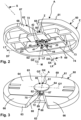
- a tractor hitch 60 is configured as a fifth wheel 60A.
- the fifth wheel coupling 60A has a coupling element 61 in the form of a so-called mounting plate 61A.
- the insertion receptacle 62 facilitates the insertion of a mating coupling element 81 of a trailer coupling 80 which has a so-called pin 82 or king pin 82 .
- the pin 82 is used to couple the trailer hitch 80 to the towing vehicle hitch 60, with the coupled state in the Figures 2-8 is shown.
- the towing vehicle coupling 60 is arranged or can be arranged on a towing vehicle Z.
- the towing vehicle Z is, for example, a so-called articulated lorry or another truck.
- the trailer hitch 80 is attached or attachable to a trailer A, for example a so-called semi-trailer.
- the kingpin or pin 82 is brought up to the coupling element 61, for example from a rear side of the towing vehicle Z or from a front side 63 of the coupling element 61, with the towing vehicle Z in practice reversing, around the semi-trailer and consequently to hitch the trailer vehicle A.
- Trailer vehicle A is supported on a top 83 of trailer hitch 80 or pivot 82 .
- the top 83 is connected, for example, to an underside of the trailer vehicle A, for example welded or screwed.
- the upper side 83 is provided on a flange body 84, the underside of which faces away from the upper side 83 forms a support surface 85 for support on the towing vehicle coupling 60.
- the support surface 85 serves to rest on a support surface 65 on the upper side 64 of the mounting plate 61A or the coupling element 61.
- the support surface 65 and the support surface 85 are preferably flat surfaces. Consequently, the trailer hitch 80 is on the contact surface 65 in supported over a large area in a horizontal plane, so that significant supporting forces do not act on the actual kingpin 82, which namely engages with a pin section 91 in a coupling receptacle 70 of the towing vehicle coupling 60.
- the end face 63 there is a slide-on slope 66 along which the support surface 85 can slide when the trailer coupling 80 is coupled to the towing vehicle coupling 60 .
- the insertion of the king pin 82 into the coupling receptacle 70 is facilitated by the insertion bevels 68, which laterally delimit the insertion receptacle 62 and run toward one another in the sense of a constriction towards the coupling receptacle 70.
- the insertion bevels 68 extend from the end face 63 in the direction of a front face 69 of the coupling element 61 or the mounting plate 61A.
- the coupling receptacle 70 has an essentially cylindrical inner contour 71, with this inner contour 71 not having to be completely cylindrical, but merely representing an enveloping inner contour, so to speak. Consequently, the pin section 91 is at least partially supported with its likewise essentially cylindrical outer peripheral contour 86 on the inner periphery of the coupling receptacle 70, so that the king pin 82 can rotate essentially about a joint axis of rotation GZ relative to the towing vehicle coupling 60.
- a support body 72 is arranged on an underside 74 of the coupling element 61 or the mounting plate 61A.
- the support body 72 is provided next to and/or below the coupling receptacle 70 .
- the support body 72 can be plate-like.
- the king pin 82 is to be inserted past the support body 72 into the coupling receptacle 70 when the trailer coupling 80 is coupled to the towing vehicle coupling 60 .
- the coupling element 61 is preferably reinforced on its underside 74 by a rib structure or by ribs 73, which makes the contact surface or support surface 65 particularly resilient.
- the trailer coupling 80 can be locked on the towing vehicle coupling 60 by a locking device 75 of the towing vehicle coupling 60 .
- the locking device 75 comprises a locking body 76 which engages in a locking receptacle 87 of the pin 82 which is provided on the outer circumference 86 thereof.
- the pin 82 can be easily introduced into the coupling receptacle 70, for example by having a slide-on bevel 89 on its end face 88, ie on the side of the pin 82 opposite the flange body 84.
- the slide-on slope 89 is provided, for example, by a rounded or conical edge section between the outer circumference 86 and the end face 88 or end face of the pin 82 .
- the locking body 76 can expediently be driven by a manual or motorized locking drive 77, so that it engages in the locking receptacle 87 in its locking position and is moved out of the locking receptacle 87 in its release position, so that the pin 82 can be moved out of the coupling receptacle 70.
- the trailer coupling 80 can rotate with respect to the towing vehicle coupling 60 preferably about the joint axis of rotation GZ, i.e. about an axis of rotation which is generally approximately vertical when driving, but also about joint axes of rotation GX and GY, i.e. about a longitudinal axis and a transverse axis, which run in particular in the longitudinal direction of the towing vehicle Z or orthogonally at right angles to the longitudinal direction of the towing vehicle Z.
- GZ joint axis of rotation
- GX and GY i.e. about a longitudinal axis and a transverse axis
- the mating coupling element 81 can rotate or pivot relative to the coupling element 61 with respect to the joint rotation axes GX, GY and GZ, so that the coupling element 61 and the mating coupling element 81 form a joint 95.
- the coupling counter-element 81 and the coupling element 61 are in a storage area 96 in bearing engagement with each other.
- the bearing area 96 is preferably approximately cylindrical.
- the trailer vehicle A when cornering relative to the towing vehicle Z, the trailer vehicle A can pivot essentially about the joint axis of rotation GZ.
- the trailer vehicle A can also swivel or rotate relative to the towing vehicle Z during a rolling movement or rolling movement about the joint axis of rotation GX and/or during a pitching movement about the joint axis of rotation GY.
- the sensor device 10 is accommodated in an accommodation space 67 below the coupling accommodation 70 .
- the receiving space 67 is a receiving space that is already present in a standard fifth wheel 60A, i.e. a structural modification is not necessary.
- Sensor device 10 is provided for rotary driving by coupling counter-element 81, which has a driving surface 90 for this purpose.
- the driving surface 90 is formed, for example, by the end face 88 or is provided on it.
- the slide-on bevel 89 or another area of the outer peripheral contour 86 can also form the driving surface 90 in whole or in part, which becomes even clearer.
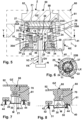
- the sensor device 10 has a driver 20 which can be carried along by the coupling counter-element 81, namely the pin or saddle pin 82, and can be rotated about a driving axis of rotation M.
- the driver 20 has a driving surface 21 for making a driving contact or a driving connection with the pin 82 .
- the driving surface 21 is provided on a free end face of the driver 20 .
- a circumferential wall 22 extends away from the driving surface 21 and extends, for example, in a substantially conical or cylindrical manner.
- the entrainment surface 21 is provided on an end wall 21A, which is designed essentially as a planar or level wall.
- the peripheral wall 22 extends away from the end wall 21A.
- annular carrier contour can also be provided on a carrier according to the invention.
- annular circumferential driving contour 27 in particular a ring, is provided, which can be in engagement with at least a partial area of the outer circumference 86 of the pin 82.
- the peripheral entrainment contour 27 can be partially ring-shaped, for example it can comprise one or more entrainment projections which protrude towards the pin 82 .
- the driver body 20A is preferably elastically deformable in the area of the driver surface 21 and/or the peripheral driver contour 27 and has an elastic section 28 there.
- the driver body 20A consists of an elastically deformable plastic or rubber, at least in the elastic section.
- a side of the carrier 20 opposite the end wall 21A is essentially closed off by a bottom wall 23, so that an essentially encapsulated or protective inner space 29A is formed.
- the end wall 21A and the peripheral wall 22 form parts of a driver body 20A.
- the driver body 20A is dome-like or hood-like and is, as it were, closed on the bottom side by the bottom wall 23 .
- the driver body 20A and the bottom wall 23 essentially encapsulate an interior space 29A.
- a protective housing 29 is formed.
- the protective housing 29 protects the components which are arranged in its interior space 29A and are explained in detail below.
- the sensor device 10 comprises a sensor 11, for example a magnetic sensor, which is arranged in the inner space 29A. From the sensor 11 Signals generated are evaluated by an evaluation device 12, which includes a processor 13 and a memory 14, for example.
- the processor 13 executes program code from at least one program which processes the sensor signals of the sensor 11 and makes them available, for example, to an interface 15, in particular a bus coupler, for an on-board network N of the towing vehicle Z.
- the interface 15 is, for example, a CAN bus interface, but can also easily be or include any other digital or analog interface.
- the evaluation device 12 is arranged, for example, on or in a housing 16 .
- a printed circuit board or another similar carrier for electronic components for example the processor 13 or the memory 14 or both, can also be provided.
- the evaluation device 12 as a whole, including the sensor 11, is accommodated in the interior space 29A, i.e. in the driver body 20A, in a protected manner.
- Sensor transmitters 25 for example magnets, which are arranged on a sensor carrier 24 serve to excite the sensor 11 .
- the sensor carrier 24 is arranged in a rotationally fixed manner on the inside of the peripheral wall 22, ie inside the driver body 20A.
- the sensor carrier 24 has a substantially annular shape. On its inner circumference, opposite the sensor 11 , the sensor carrier 24 has sensor element receptacles 26 for the sensor transmitters 25 .
- the sensor transmitter 25 and the sensor element holders 26 are arranged in a ring around the driving axis of rotation M of the driver 20 and form a ring arrangement 25B.
- the sensor transmitters 25 are rotated past the sensor 11, as a result of which a high level of measuring accuracy can be achieved.
- the sensor device 10 in particular the evaluation device 12 , is connected to the vehicle electrical system N via a line arrangement VX connected to the interface 15 . Consequently, a wired coupling of the sensor device 10 to the vehicle electrical system N is implemented, with the same as in the case yet to be explained Embodiment according to Figures 9, 10 a wireless connection is also possible, for example via infrared, radio or the like.
- the driver 20 is rotatably mounted on a bearing body 30 about the driving axis of rotation M.
- the bearing body 30 is designed, for example, as a bearing shaft or bearing axle.
- the bearing body 30 At its end region directly opposite the end wall 21A, the bearing body 30 has a flange projection 31 on which a rotary bearing 33 is held.
- Another rotary bearing 34 is provided in the area of the bottom wall 23 and is supported on the bearing body 30 by means of a support body 39 .
- the pivot bearings 33, 34 are preferably roller bearings, in particular ball bearings, roller bearings or the like, which is why the driver 20 rotates easily about the entrainment axis of rotation M.
- the bearing body 30 is held against rotation with respect to the entrainment axis of rotation M by means of an anti-rotation device 35 on a holding device 40 which is provided for holding the sensor device 10 on the towing vehicle coupling 60 .
- the holding device 40 has a holding plate 41 on which the bearing body 30 is supported or in front of which the bearing body 30 protrudes.
- the retaining plate 41 forms a carrier 47 for the bearing body 30.
- the anti-rotation device 35 includes a screw 36 which is screwed into a screw mount 36A.
- the screw 36 penetrates a screw opening on the holding plate 41 which is eccentric to the entrainment axis of rotation or central axis of the bearing body 30 .
- the bearing body 30 has an elongate shape extending along the entrainment axis of rotation. A distance is provided between the rotary bearings 33, 34, in which the sensor 11 is arranged.
- the pivot bearings 33, 34 spaced apart or spaced apart from one another provide optimal support for the driver 20 on the bearing body 30 in relation to the driving axis of rotation M, so that the driver 20 is optimally supported transversely to the driving axis of rotation M.
- the bearing body 30 also has a receiving space 30A for the sensor 11 and the evaluation device 12.
- a channel 37 for the lines of the line arrangement VX runs from the receiving space A and opens out at the retaining plate 41.
- a passage opening 46 is provided there for the line arrangement VX, through which the lines of the line arrangement VX are routed.
- the line arrangement VX includes, for example, a data connection DV, which includes one or more bus lines. Furthermore, supply connections V1, V2, for example a low DC voltage of 5-10 volts and ground, are components of the line arrangement VX.
- the driver 20 is movably mounted with respect to the coupling element 61, in particular the coupling receptacle 70, so that it participates in different movements, so to speak, particularly when the trailer coupling 80 is coupled to the towing vehicle coupling 60 of the entrainment axis of rotation M.
- the slide-on slope 89 can move the driver 20 out of its position in the figures 4 and 5 illustrated position, in which the driver axis of rotation M is, so to speak, aligned with the joint axis of rotation GZ or is parallel to it, so that the driver 20 is deflected from its central position by degrees of rotational freedom DX and DY and/or linear degrees of freedom of movement LX, LY and LZ can be.
- the pivoting degrees of freedom or rotational degrees of freedom DX, DY run orthogonally to the driving axis of rotation M and orthogonally to one another.
- the carrier 20 can pivot with the rotational degree of freedom DX about an axis SX that is parallel to the joint rotational axis GX.
- the driver 20 can be linearly deflected about the axis SX parallel to the joint axis of rotation GX, ie moved at right angles to the driving axis of rotation M.
- the further linear degree of freedom of movement LY allows a deflection or displacement of the driver 20 transversely to the degree of freedom of movement LX or to the X axis and/or along an axis SY which is parallel to the joint axis of rotation GY.
- the driver 20 rotates about this axis SY, which is parallel to the joint axis of rotation GY.
- the ability to move with the degree of freedom of movement LZ is provided parallel or coaxially to the driving axis of rotation M, e.g. about an axis SZ.
- All of the aforementioned rotational degrees of freedom DX, DY or linear degrees of freedom of movement LX, LY or LZ make it possible for driver 20 to be deflected from its central position, for example when coupling trailer hitch 80 to towing vehicle hitch 60, so that its end wall 21A is attached to end face 88 or .
- This can be seen in particular in the Figures 7 and 8 .
- the rotary driving coupling of the driver 20 is also made possible with a deflection transverse to the driving axis of rotation M, see in particular figure 8 .
- the driver 20 swivels about with the rotational degree of freedom DX or DY in the illustration according to FIG figure 8 , but still remains in driving contact with the pin 82.
- an inclined surface 22A or insertion bevel is preferably provided, along which counter-coupling element 81 can slide when being coupled to coupling element 61, i.e., for example, when being inserted into coupling receptacle 70.
- the coupling element 61 can, for example, tilt or pivot the driver 20 transversely to the driving axis of rotation M and/or adjust it along the driving axis of rotation M.
- the mobility of the driver 20 about the degrees of freedom of movement DX, DY, LX, LY and LZ is provided by the holding device 40 on which the bearing body 30 is fixedly arranged, ie is immobile.
- the holding plate 41 is fixed to the underside 74 of the mounting plate 61A.
- holding projections 42 of the holding plate 41 protrude in front of a base body of the same and/or are provided on the corner regions of the holding plate 41 .
- the holding projections 41 have passage openings 43 for screws 44 which are screwed into the coupling element 61 and/or the support body 72 from its/their underside 74 .
- welding studs could also be provided, for example, the longitudinal end regions of which are welded to the coupling element 61, advantageously using so-called capacitor welding or resistance welding.
- Springs 52 of a spring arrangement 51 are provided between the heads 44A of the screws 44 and the retaining plate 41 and are supported on the one hand on the heads 44A and on the other hand on the retaining plate 41 and thus on the bearing body 40 .
- the springs 52 thus act as a force-applying means 50 in such a way that they press the driver 20 in the direction of the pin 82 so that its end wall 21A is pressed against the end face 88 of the pin 82 .
- the bearing body 30, i.e. the bearing shaft or bearing axle, is arranged in a receiving recess 45 of the holding device 40 or the holding plate 41 and protrudes in the direction of the coupling receptacle 70 and thus when the trailer coupling 80 is coupled to the towing vehicle coupling 60 toward the pin 82.
- a magnet 53 which is arranged between the bearing body 30 and the end wall 21A of the driver 20, enables an additional force in the sense of a driving coupling.
- the magnet 53 acts in the direction of the pin 82 with its magnetic attractive force.
- the magnet 53 is sandwiched between an end face 38 of the flange or flange projection 31 of the bearing body 30 and the end wall 21A.
- a shield 54 is provided, which is arranged between the magnetic sensor transmitters 25 and the magnet 53 .
- the shielding 54 consists of a flux guide plate or has one.
- the shield 54 is preferably sandwiched between the face 38 of the bearing body 30 and the magnet 53 .
- a side of the Magnet 53 completely shielded by the shield 54, which is, for example, plate-like.
- the shielding 54 can also shield the magnet 53 on the peripheral side, for example with a shielding wall 54A, which protrudes in front of the plate-like or wall-like shielding 54 and can be in one piece with it.
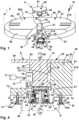
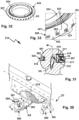
- a multi-axis swiveling capability with a joint 195 is also provided when a trailer coupling 180 is coupled to a towing vehicle coupling 160 .
- the towing vehicle coupling 160 has a ball head 162 as a coupling element 161 .
- the ball head 162 is arranged on a free end area of a coupling arm 165 which is attached or can be releasably attached to the rear of a towing vehicle Z2, for example a passenger car.
- the coupling arm 165 has, for example, a mounting section 166, in particular a plug-in section for attachment to the towing vehicle Z2.
- a vehicle mount 170 is arranged on the towing vehicle Z2, for example.
- the vehicle mount 170 includes a receiving body 171 which is in particular detachably attached to a cross member or other holding structure at the rear of the towing vehicle Z2.
- a plug-in receptacle 172 for plugging in the mounting section 166 is present on the receiving body 171 .
- Form-fitting contours 167 for example wedge bevels or similar other form-fitting contours, are provided on a foot region of the mounting section 166 for form-fitting engagement in form-fitting counter-contours 174 on the receiving body 171 .
- the coupling arm 165 is additionally held on the vehicle mount 170 by means of a locking device 175.
- the locking device 175 comprises, for example, a locking body 176, in particular balls, bolts or the like, which can be actuated by an actuating body 177, with a corresponding actuation in a locking receptacle , in particular a groove on the inner circumference of the plug-in receptacle 172 can be actuated into a locking engagement.
- the actuating body 177 is bolt-like and can be actuated in the longitudinal direction of the mounting section 166, which is indicated by a double arrow.
- a motor drive or how In the present case, a manual drive 178 can be provided, which can be driven by a hand-operated element 179, in particular a handwheel.
- a pinion for example, engages in a toothing on the operating body 177 in order to adjust the latter along its direction of longitudinal extension, as a result of which the locking bodies 176 are actuated radially outwards in front of the same through openings on the mounting section 166, in order to move into the Intervene locking receptacle 173.
- a fixed attachment of the coupling arm 176 to the towing vehicle Z2 can also be provided, or storage using a schematically illustrated bearing 270, on which the coupling arm 165 can be moved, for example, between a usage position in which the rear end, in particular a bumper, of the Towing vehicle Z2 protrudes, and a non-use position in which it is at least essentially hidden behind and / or moved back under a rear contour of the towing vehicle Z2, for example behind a bumper of the towing vehicle Z2.
- the clutch arm 165 can pivot about a pivot axis SA of the bearing 270 .
- the trailer hitch 180 is designed as a ball hitch.
- the coupling element 181 is a coupling receptacle 182 in which the ball head 162 and thus the coupling element 161 can engage in a manner known per se in the sense of a ball joint.
- the ball head 162 is mounted in the coupling receptacle 182 so that the two bodies are in engagement with one another in a bearing area 196 .
- the coupling counter-element 181 can pivot on the coupling element 161 about joint rotation axes GZ, GX and GY, with the joint rotation axis GZ being an axis which is essentially vertical when driving, while the other two joint rotation axes GX and GY are in the longitudinal direction of the towing vehicle Z2 and each run horizontally in the transverse direction thereto.
- these coordinates or orientation of the axes of rotation can also be configured differently.
- the trailer hitch 180 comprises, for example, a drawbar or is arranged with a mounting section 183 on a drawbar.
- a locking device 185 is used to lock trailer coupling 180 on towing vehicle coupling 160.
- Locking device 185 comprises a locking element 187, for example a clamping jaw or closing jaw, which can be adjusted on a pivot bearing 184 between an open position OP and a closed position LO, with the open position the coupling element 161 can be removed from the coupling counter-element 181, but not in the closed position LO.
- a hand-operated element 186 for example with a handle, is used to actuate the locking element 187.
- the sensor device 110 can be retrofitted to the towing vehicle coupling 160 without further ado, without the elements that are to be coupled, namely the coupling element 161 and optionally the coupling counter-element 181, having to be modified in any way.
- the towing vehicle coupling 160 cannot be changed in the area of a cylinder section 163, in particular a shaft with which the coupling element 161 is held on the coupling arm 165, in particular its upper arm section 164.
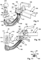
- sensor device 110 is fastened to the end region of coupling arm 165, in particular to arm section 164 close to cylinder section 163, so that a driver 120 of sensor device 110 can come into driving contact with trailer coupling 180.
- the driver 120 is thereby on the front side of the coupling counter-element 181, in particular an edge area of the coupling receptacle 182, rotationally driven, so that it rotates together with the coupling counter-element 181 when this is rotated about the joint axis of rotation GZ, for example when cornering a combination consisting of towing vehicle Z2 and trailer A2, on which the trailer coupling 180 is arranged.
- the trailer hitch 180 cannot only pivot about the joint axis of rotation GZ, which can be easily detected by the driver 120 and by arranging the driver 120 as, for example, in document EP 2 415 620 A1 described is possible, but also about the joint rotation axes GX and GY.
- a so-to-speak floating or multi-articulated mounting of the driver 120 with respect to the coupling element 161, in particular with respect to the coupling arm 165 is provided.
- the driver 120 has a driving surface 121 which is associated with and/or faces the end face 188 of the coupling receptacle 182 and is in particular ring-shaped.
- the driver 120 has a driver body 122 on which the driver surface 121 is provided at the end.
- a side of the driver body 122 or the driver 120 that faces away from the driver surface 121 is designed as a bearing section 123, which is rotatably mounted on a bearing body 130 and can also be rotated about rotational degrees of freedom DX and DY.
- the rotational degrees of freedom DX and DY are provided about rotational axes that are parallel to the joint rotational axes GX and GY.
- the driver 120 it is possible or conceivable for the driver 120 to be able to move linearly with respect to the bearing body 130, for example about axes parallel to the joint rotation axes GZ, GX and GY.
- a linear degree of freedom of movement LZ can be provided parallel to the driving axis of rotation M.
- the driver 120 is rotatably mounted on the bearing body 130 about the driving axis of rotation M and can be pivoted transversely to the driving axis of rotation M, namely with the rotational degrees of freedom DX and DY.
- the driver 120 can thus participate in pivoting movements of the trailer hitch 180 about the joint rotation axes GX and GY without the driving contact or the coupling between the driver 120 and the coupling counter-element 181 being interrupted.
- the bearing body 130 is ring-shaped.
- the bearing body 130 is fastened, for example, to the arm section 164, for example with a screw 141 of a holding device 140.
- the clamping screw 141 runs, for example, radially to the arm section 164 and clamps the bearing body 130 to the coupling arm 165.
- Force application means 150 are provided between the driver 120 and the bearing body 130, for example with a spring arrangement 151.
- the spring arrangement 151 comprises one or more springs 152 which are supported on the bearing body 130 and on the driver body 122 or driver 120.
- the springs 152 are supported on an edge or support section 124 of the driver body 122 .
- the support section 124 for example a step, a recess or the like, is arranged between the bearing section 123 and the driving surface 121.
- a further application of force to the driver 120 in the direction of the trailer hitch 180 is given, for example, by a magnet 153 which is arranged on the driver 120 .
- Magnet 153 (several magnets arranged in particular on the outer circumference of driver 120 can also be provided) applies a magnetic force to driver 120 in the direction of end face 188 or in the direction of coupling counter-element 181.
- the coupling process of the trailer hitch 180 to the towing vehicle hitch 160 is in the Figures 12 and 13 clarified. It can be seen that the coupling counter-element 181 comes into driving contact with the driver 120 when it is coupled to the towing vehicle coupling 160, ie the spring arrangement 151 is compressed, for example, when the coupling socket or the coupling receptacle 182 is placed on the ball head 162.
- the coupling counter-element 181 of the trailer hitch 180 rotates about the entrainment axis of rotation M, it takes the driver 120 with it, so that the sensor arrangement 110 based on the sensor or sensors 111 a respective The angular position of the driver 120 relative to the bearing body 130 and thus relative to the towing vehicle Z2 or the towing vehicle clutch 160 can be detected.
- Sensor transmitters 125 are arranged on driver 120, in particular a ring arrangement with several sensor transmitters or magnets 125 arranged around the outer circumference of coupling arm 165, the respective position of which can be detected by at least one sensor 111 or several sensors, for example two sensors 111a and 111b .
- the sensors 111 therefore detect the magnetic field of the sensor transmitter 125 and thus the angular position of the coupling counter-element 181 in relation to the coupling element 161.
- Evaluation device 112 has an interface 115, in particular a radio module or some other wireless interface, for communication with vehicle electrical system N.
- a receiver 116 On the towing vehicle Z2, in particular in the area of the vehicle mount 170, there is a receiver 116, which in particular forms a component of the sensor device 110 or forms a system together with the sensor device 110, for receiving sensor signals which determine the angular position of the trailer hitch 180 relative to the Represent towing vehicle clutch 160 about the entrainment axis of rotation M.
- the receiver 116 can have, for example, a bus interface and/or an energy supply interface or the like for coupling and/or connection to the vehicle electrical system N of the towing vehicle Z2.
- a battery (not shown), a rechargeable battery or the like can be present, for example.
- a power supply using a photocell or another device suitable for generating electrical energy is also readily conceivable.
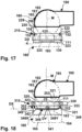
- a sensor device 210 which has similar components to the sensor device 110 already explained.
- a driver 220 of the sensor device 210 is at least as a cover, preferably as a protective housing 229, for at least a sensor 111 and preferably also the bearing body 130.
- a driver body 222 basically corresponds to the driver body 122, but does not engage in an interior of the bearing body 130, but has a cover section 221 in which the bearing body 130 is at least partially accommodated.
- the driver body 222 can optionally be closed on a side facing away from the driver surface 121 by a cover 223, which is preferably ring-shaped and can have a passage opening 225 for the coupling arm 165, in particular its cylinder section 163 and the upper area of the arm section 164.
- a seal, in particular a sealing ring, a seal with, for example, silicone or another joint compound can be provided at the passage opening 225 .
- the cover 223 is connected at the end to the driver body 222, for example glued, welded or the like. Cover 223 and driver body 222 together form a protective housing 229 for the at least one sensor 111 and preferably the bearing body 130.
- a sensor device 310 is provided for arrangement on the towing vehicle coupling 160 .
- it has a retaining device 340, for example a retaining ring 342, which is attached to the cylinder section 163 and/or arm section 164 of the towing vehicle coupling 160, for example clamped, glued or the like.
- a corresponding clamping screw is not shown in the drawing for reasons of simplification.
- the holding device 340 has a bearing mount 341 for a bearing section 331 of a bearing body 330 .
- the storage section 331 and the bearing mount 341 are, for example, sections of a ball-and-socket bearing or ball-and-socket joint 349, ie they have, for example, spherical segments or are designed like spherical segments. Consequently, the bearing mount 341 is designed, for example, in the manner of a receiving shell.
- the bearing body 330 can swivel in a ball-and-socket manner with respect to the retaining ring 342, so that a driver 320 that is mounted on the bearing body 330 so that it can rotate about the driving axis of rotation M can also follow movements of the trailer hitch 180 about the joint axes of rotation GX, GY, so to speak, so that its driving surface 321 in driving contact with the face 188 of the trailer hitch 180 remains.
- a cardan joint 348 is also possible, which in figure 18 with gimbal elements 348X and 348Y, whose longitudinal axes form gimbal axes.
- the gimbal element 348X for example, enables pivoting with the rotational degree of freedom DX.
- the gimbal element 348Y is drawn from its front side and enables pivoting with the rotational degree of freedom DY, which is indicated by an arrow in the drawing.
- the driver 320 is rotatably mounted on the bearing body 330 by means of a roller bearing 333, in particular a ball bearing or roller bearing, about the driving axis of rotation M.
- the friction of the roller bearing 333 is preferably low, so that the trailer hitch 180 can take the driver 320 with it and rotate it particularly easily.
- Sensor 111 is arranged on bearing body 330 so that sensor transmitters 25, in particular magnets, on driver 320, which are arranged in an interior space of bearing body 330, rotate about driving axis of rotation M, but do not pivot transversely thereto or in any other way change their location. As a result, optimal signal detection by the sensor 111 can be implemented without further ado.
- the sensor transmitters 25 are arranged, for example, on a bearing section 323 of the bearing body 320 on which the roller bearing 333 is supported.
- a spring arrangement with springs 352, for example, serves as force application means 350, which are arranged between bearing body 330 and holding device 340 and thus not only force bearing body 330, but also driver 320, which is mounted on bearing body 330 so that it can rotate about the driving axis of rotation M, in the direction of the Apply counter-coupling element 181.
- a magnet or a magnet arrangement 353 can also be provided as the force application means 350 , which is arranged on the driver 320 and applies a magnetic force to it in the direction of the coupling counter-element 181 .
- Sensor device 110 includes an evaluation device 112, which is arranged, for example, on or in bearing body 130 ( figure 10 ).
- the evaluation device 112 includes, for example, a processor 13 and a memory 14 in which one or more program modules can be stored, the program code of which is provided by the processor 13 for evaluating the sensor signal of the sensor 111 or the sensors 111a, 111b.
- the magnetic measurement principles or sensor principles of the sensor device 10, 110 are not the only embodiment.
- inductive, capacitive or optical sensors can be provided, also in combination.
- optical markings, in particular lines or the like can be provided, which can be detected by an optical sensor 11, 111.
- Capacitive detection is also easily possible if, for example, corresponding electrical fields are provided by the sensor transmitters.
- the sensory detection of a relative position of a carrier relative to a carrier or bearing body can also be implemented by at least one sensor which is arranged on the carrier and thus rotates about the carrier axis of rotation relative to the bearing body or carrier.
- the drivers 120, 220, 320 can be made entirely or partially of an elastic material, such as a flexible plastic, rubber or the like. Elastic resilience in the area of the driving surface 21 is particularly advantageous.
- the evaluation device 112 already explained can be provided for the respective sensor 111.
- a sensor device 610 is suitable for being taken along by the counter-coupling element 81 of the trailer hitch 80 about the driving axis of rotation M.
- the sensor device 610 includes a holding device 640 which can be attached to the supporting body 72 of the towing vehicle coupling 60 in the manner of the holding device 40 .
- the holding device 640 has a holding plate 641 on which a holding part 645 for fastening a bearing body 630 is provided.
- Fastening parts 645A, 645B extend away from the holding part 645 and are designed, for example, in a stepped manner.
- the parts 645, 645A and 645B each run in a stepped manner relative to one another.
- Retaining projections 642 are provided on the fastening parts 645A, 645B, which are suitable, for example, for screwing to the support body 72 of the towing vehicle coupling 60 using the screws 44, for example.
- the bearing body 630 is used to mount the driver 620 about the entrainment axis of rotation M.
- an upper pivot bearing 33 is arranged on an end region of the bearing body 630 that faces away from the retaining plate 641, in particular on a flange projection 31.
- a further bearing 34 is provided for axis of rotation M.
- the bearings 33, 34 form a bearing arrangement 32 which supports the driver 20 so that it can rotate about the driving axis of rotation M with respect to the bearing body 630.
- the rotary bearing 34 is arranged on a support body 39 which in turn is supported on the bearing body 630 .
- the driver 620 is similar to the driver 20 in that it has a peripheral wall 622 and an end wall 621A and is, for example, essentially cylindrical or conical, in particular is mushroom-shaped.
- the end wall 621A is provided for rotary driving by the mating coupling element 81 .
- the driver 620 forms a protective housing 29 with a protected interior 29A, in which the electronic components of the sensor device 610 are arranged, in particular the sensor 11 already explained. This is located in the interior of the sensor carrier 24, on which at least one sensor transmitter 25, e.g. a magnet , is arranged to actuate the sensor 11.
- the bearing body 630 has a channel 637 which communicates with a passage opening 646 of the holding plate 641 so that a line arrangement VX can be routed to the evaluation device 12 and the sensor 11 through these two components.
- a magnet 653 like the magnet 53 is arranged on the end wall 621A.
- the magnet 653 is disposed in a shield 654 having, for example, a bottom wall 654A and a peripheral wall 654B.
- the bottom wall 654A is perpendicularly interspersed with the follower axis of rotation M, while the peripheral wall 654B extends about the follower axis of rotation M.
- the magnet 653 is thus shielded from the sensor 11 and cannot influence it.
- the sensor device 610 also allows the holding device 640 to move relative to the support body 72 or the towing vehicle coupling 60 .
- bearing bodies 644 are provided, which penetrate through openings 643 of the holding device 640 on the holding projections 642 and are connected with fastening sections 644C to the towing vehicle coupling 60, in particular the support body 72, for example screwed, glued or welded.
- screw threads can be provided on the fastening sections 644C.
- the bearing bodies 644 are advantageously designed like bolts.
- the bearing bodies 644 form components of bearing devices 655 which support the holding device 640 in relation to the support body 72 so that it can be pivoted as well as slidably.
- the bearing devices 655 each include a pivot bearing 656, in particular a multi-axis pivot bearing, namely a ball bearing, and a sliding bearing 657.
- Bearing receptacles 656A of the pivot bearing 656 are provided on the bearing bodies 658 .
- a bearing body 659 in the manner of a ball or partial ball is accommodated in the bearing receptacles 656A.
- the bearing body 656 can pivot in multiple axes in the bearing receptacle 656A, for example about the axes SX and/or SY or axes parallel thereto.
- a bearing seat 657A namely a slide bearing seat, for the bearing body 644 is provided.
- the bearing body 644 is thus longitudinally displaceable in the bearing receptacle 657A along a displacement axis ZZ, which is indicated by a double arrow PZ.
- the pivotability of the bearing body 644 with respect to the bearing mounts 655A or the pivotability of the bearing body 658 about the bearing body 659, so that namely the holding device 640 can pivot with respect to the bearing body 644, is indicated by dashed lines.
- the holding device 640 in particular the holding plate 641, can be displaced axially both about the axis direction PZ with respect to the respective bearing body 644, and also about mutually angled pivot axes, which are located at the intersection of the central longitudinal axis of the bearing body 644 with the central plane of the holding plate 641 in the area of the respective holding projection 642 are pivoted.
- the drawing shows how the holding plate 641 can be deflected due to the mobility at the pivot bearings 656 and sliding bearings 657.
- the deflection is exaggerated in the drawing. In practice, a slight deflection of a few degrees, for example, is sufficient to enable or facilitate a deflection of the driver 620 from its central position for the coupling counter-element 81 to allow it to slide onto the end wall 621A.
- bearing bodies 658 are accommodated in passage openings 643 with play of movement transverse to displacement axis ZZ or the longitudinal axis of sliding bearing 657.
- a bearing area 643A of the holding plate 641 projects in the area of the respective passage opening 643 into a bearing receptacle 658A, for example a bearing groove, on the bearing body 658.
- the bearing area 643A can be circular, for example, but can also have other contours, for example a slot. Accordingly, for example, an oval or elongated bearing area 643B can also be provided, which is indicated schematically.
- the bearing receptacle 658A can be a circumferential groove on the bearing body 658, for example.
- the bearing body 658 is thus movably received in the passage opening 643 transversely to the direction of movement, which is indicated by the double arrow PZ. As a result, tension can advantageously be avoided.
- bearing body 658 it would also be possible to connect the bearing body 658 to the holding plate 641 using an elastomer, for example, so that the bearing body 658 is accommodated in the holding plate 641 in a floating manner, so to speak.
- the retaining plate 641 is also subjected to a force with respect to the bearing body 644, namely by a force application means 650.
- the force application means 650 comprises a spring arrangement 651 with springs 652.
- the springs 652 are each supported on a head 644A of a bearing body 644 on the one hand and on the other hand on a head 644A of a bearing body 644 or the holding device 640 stationary or immovable component, for example one of the bearing body 658 or 659.
- the springs 652 are penetrated by a bearing section 644B of a respective bearing body 644 .
- the bearing section 644B is accommodated in the bearing receptacle 657A in a longitudinally displaceable manner.
- the driver 620 is constructed in several parts. It has a driver carrier 667 which is similar to the driver 20 in terms of its basic contour, namely having an end wall 668 and the peripheral wall 622 .
- the driver carrier forms that Protective housing for, among other things, the sensor 11 and the evaluation device 12 and is rotatably mounted on the bearing body 630 by means of the bearing arrangement 32 .
- a driver body 660 is detachably fastened to the driver carrier 667, for example glued, screwed or the like.
- the driver body 660 forms the wearing part, so to speak, which can be easily replaced, while the driver carrier 667 remains permanently on the bearing body 630.
- an underside 666 of the driver body 660 is glued to the end wall 668 and/or lies flat against it.
- a screw arrangement with screws 665 can be provided for detachable attachment, which penetrate a base body 661 of the driver body 660 at passage openings 664 and are screwed into screw receptacles 669 of the driver carrier 667 .
- the driver body 660 has a receptacle 663 for the magnet 653 in the center with respect to the driver axis of rotation M.
- the shielding 654 is accommodated in the receptacle 663 .
- a plurality of recesses 662 extend on the radial outer circumference of the receptacle 663, which are used, for example, for the driver body 660 to be more easily compressible at its edge region, which can make it easier for the coupling counter-element 81 to slide onto the driver 620.
- the edge region of the driver body 660 extending around the recesses 662 is inclined flat and has the bevel 622A.
- the recesses 662 can also serve to ensure that the driver body 660 is particularly light or that little material is required for it.
- the recesses 662 can also serve to ensure that the driver body 660 can be produced in a dimensionally stable manner.
- the magnet 663 and/or the shielding 654 can be glued, inserted or screwed into the material of the driver body 660 . However, it is also possible to overmold the magnet 653 and/or the shielding 654 with the material of the driver body 660 .
- the end wall 621A or end face of the driver 620 is designed as a frictional contact surface 681 and is used for frictional driving contact between the driver 620 and the mating coupling element 81. It would now be possible to place the frictional contact surface 681 directly on a free end face or flat side 653A of the Provide magnets 653, for example by firmly connecting the particles 683, which will be explained below, to this free end face 653A by means of an adhesive bond or other lamination.
- a separate frictional engagement body 680 is provided.
- the friction-locking body 680 is, for example, plate-like or foil-like and firmly arranged, for example glued, on the free end face 653A of the magnet 653 .
- the frictional engagement body 680 can also be formed from a material of the driver body 660 which encloses the magnet 653 and in which the particles 683 are directly embedded.
- the frictional engagement body 680 has the frictional engagement surface 681 on its side facing away from the magnet 653 .
- the particles 683 protrude in front of a supporting surface 682 of the frictional engagement body 680 .
- the frictional engagement body 680 is bonded to the end face 653A of the magnet 653 using an adhesive layer 686 .
- the frictional engagement body 680 has a base body or a base layer 685, which has the adhesive layer 686 on the one hand and a support layer 684 for the particles 683 on the other hand on opposite sides.
- the backing layer 684 which can also be referred to as a binding layer or adhesive layer, carries the particles 683. These are embedded in the backing layer 684, so to speak, and protrude freely from the same.
- the particles 683 protrude in front of the supporting surface 682 in the manner of pyramids, for example.
- their tips 687 for example pyramid tips, protrude in front of the support surface 682 like a spike, so that they can penetrate like a spike into the end face 88 of the counter-coupling element 81, and consequently the driving surface or friction-locking surface of the counter-coupling element 81.
- From the tips 687 the side surfaces of the particles 683 run towards the supporting surface 682, edges 688 being formed between the respective side surfaces.
- a central surface 690 of the frictional contact surface 681 is free of particles 683.
- the supporting surface 682 is free there.
- the driving axis of rotation M passes through the central surface 690 .
- the particles 683 run from the central surface 690 or the entrainment axis of rotation M along rays 689, ie they are arranged regularly.
- the tips 687 or the free end areas of the particles 683 protrude approximately the same distance in front of the support surface 682 .
- the peaks 687 do not "pierce" an envelope 691.
- the envelope 691 is a flat surface or flat surface, corresponding to the flat or flat surface of the end face 88 of the mating dome element 81.
- the radial arrangement of the particles 683 on the support surface 682 alone results in a higher concentration of particles 683 near the central surface 690 than on the radially outer edge area of the frictional engagement body 680 or the frictional engagement surface 681.
- the particles 683 are arranged in the shape of a ring or circular ring around the entrainment axis of rotation M.
- a chaotic arrangement or an arrangement with different distributions or fields would also be possible.
- the angular spacing between the particles 683 may be smaller at the radially outer perimeter than near the central surface 690, other than as shown in the drawing.
- the particles 683 are preferably corundum, quartz, rock particles or similar other hard material with sharp breaking edges and in any case points.
- the backing layer 684 contains glue and/or epoxy resin, for example, in order to glue or bind the particles 683 to the base layer 685 .
- the support layer 684 and/or the base layer 685 and/or the adhesive layer 686 can be elastic components and/or consist of an elastic material or contain an elastic material.
- a cover layer 692 for example made of wax or the like, can also be provided for better retention of particles on a frictional contact surface or supporting surface. However, it is advantageous if the edges 688 at least partially, but in any case the pyramid tips or tips 687, of the particles 683 protrude in front of the cover layer 692.
- the cover layer 692 is expediently made of a softer material than the particles 683 so that they can make contact with the mating dome element 81 .
- the distribution and/or arrangement of particles on a frictional engagement surface can also be configured differently than in the aforementioned exemplary embodiment, which should become clearer using frictional engagement bodies 780, 880.
- These essentially correspond to the friction-locking body 680, i.e., for example, that there is a base layer, a base layer and an adhesive layer.
- the particles 683 of the frictional engagement surfaces 781, 881 of the frictional engagement bodies 780, 880 could also be provided directly on the driver body 660 or the magnet 653.
- the particles 683 are arranged in rings 793 , 794 , 795 in the frictional engagement body 780 , for example, which run concentrically around a center point of the circular frictional engagement body 780 .
- the supporting surface 782 is exposed between the rings 793-795, in which the particles 683 are embedded in the rings 793, 794, 795.
- the center 790 or the central surface 790 of the frictional engagement body 780 is also free of particles 683, so that the supporting surface 782 is exposed there for the coupling counter-element 81 to be carried along by frictional engagement directly.
- the particles 683 are arranged in angular segments 893, which radiate, for example, around the driving axis of rotation M get lost. Between the angular segments 893, where the particles 83 of the frictional engagement surface 881 of the frictional engagement body 880 are located, angular segments of the support surface 882 are also exposed, ie without particles.
- a sensor device 410 has, so to speak, a central bearing for a driver 420 which is essentially the same as driver 620 .
- Driver 420 therefore also has a driver body 460, which is provided for the actual frictional engagement or driving contact with the mating coupling element 81 and is similar to driver body 660, and a driver carrier 467, which carries driver body 460 corresponding to driver carrier 667.
- the driving carrier 467 is mounted on the bearing body 430 by means of the pivot bearings 33, 34, which are at a longitudinal distance in relation to the driving axis of rotation M Bearing body 430 is penetrated.
- a flange projection or the like can of course also be provided, which protrudes radially in front of the bearing body 430.
- the protective housing formed by the driver carrier 667 is covered by a bottom wall 23 through which the bearing body 430 penetrates.
- the bearing body 430 is supported on a holder 440 which is connected to the support body 72 by means of screws 444 which are screwed into the support body 72 and whose heads 444A bear against a holder plate 441 of the holder 440.
- the retaining plate 441 is stationary with respect to the towing vehicle coupling 60, in particular its support body 72.
- driver 420 The mobility of driver 420 is ensured by a bearing device 455, with which the bearing body 430 is movably mounted on the holding device 440, in particular the holding plate 441, namely in a sliding manner with a linear degree of freedom of movement LZ parallel to the driving axis of rotation M, and transversely to the entrainment axis of rotation M by one or more degrees of freedom of rotation, namely about axes SY and SX.
- the bearing device 455 has a multi-joint pivot bearing 456 designed as a ball bearing.
- a bearing body 459 which is spherical or in the shape of a spherical segment on its outer circumference, is pivotably mounted in a bearing body 458, which is stationary with respect to the holding device 440, for example on the holding plate 441, namely in a bearing receptacle 456A.
- the bearing body 459 in turn has a slide bearing mount 457A which is provided with a slide bearing 457 .
- the bearing seat 457A is penetrated by a bearing section 433 of the bearing body 430, which protrudes in front of the driver 420.
- the bearing section 433 can therefore be linearly displaced in the bearing mount 457A in relation to the axis GZ or the entrainment axis of rotation M and can pivot transversely to this axis using the pivot bearing 456 on one or more axes.
- the linear displacement is shown in dashed lines in the cross-sectional view.
- the pivoting mobility is also indicated with dashed lines in the side view, but is particularly greatly exaggerated in the drawing.
- the frictional engagement surface 681 can of course also be configured differently, so that one of the frictional engagement bodies 780 or 880 is arranged there, for example.
- one of the frictional engagement bodies 680, 780 or 880 can also easily be arranged in the sensor device 10 on the end wall 21A, for example by gluing or the like.
- the particles 683 can also be directly embedded in the end wall 21A.
- the driver 20 consists of a plastic material, in particular an elastic plastic material, in particular a rubber material, into which particles, in particular corundum, glass splinters or similar other sharp-edged particles can easily be sprinkled during the manufacturing process.
- the principle with particles on friction contact surfaces can also be easily implemented in the sensor devices 110, 210 or 310 if, for example, the driving surfaces 121, 321 are provided with particles 683.
- a sensor device 510 for a towing vehicle coupling 560 is arranged, for example, directly on its coupling element 561, for example a coupling ball 562.
- the tang 520 is annular and extends near the equator of the sphere 562 but not on the equator of the sphere.
- the ring-shaped carrier 620 can rotate about a carrier axis of rotation M, about which it is rotatably mounted on the coupling element 561 .
- the driver 520 is rotatably mounted in a bearing seat 518, which extends on the radial outer circumference, close to the spherical surface of the ball 562, over its entire outer circumference.
- a partially ring-shaped configuration of a driver of the type described below would also be possible.
- the coupling element 561 has a sensor receptacle 517 in which an evaluation device 512 and a sensor 511 for detecting signals from sensor transmitters 25, for example magnets, are arranged.
- the carrier 520 has a carrier body 527 which is attached to a carrier carrier 524 .
- the driver carrier 524 has one or more sensor transmitters 25 which are arranged in a ring and extend around the driver axis of rotation M. So when the driver carrier 524 rotates about the driver axis of rotation M, the magnets or other sensor transmitters rotate past the sensor 511 so that the sensor can detect a respective angular position.
- this is embedded, for example, in a holding mass 519 or another similar holding body.
- This body also has a section of the bearing groove or bearing seat 518 .
- the driver 520 in particular its driver body 660, has a plurality of driver projections 521 on its radial outer circumference 522, between which distances or intermediate spaces 523 are arranged.
- the driver projections 521 can be displaced into the spacings 523 when a pressure coming radially from outside, namely by the trailer hitch 180 or its coupling counter-element 181, acts on a driver projection 521.
- a plurality of particles 683 are arranged on the driving projections 521, the tips of which protrude radially outwards in front of the respective driving projection 521 and can accordingly produce a frictional contact on the mating coupling element 181 when the trailer coupling 180 is on the towing vehicle clutch 560 is coupled.
- the coupling element 561 is arranged on a coupling arm 565 and can be adjusted between a use position GS and a non-use position NG using a bearing 570, for example pivoted on one or more axes and/or linearly displaced or the like. It is of course possible to lock the coupling arm 565 in the use position GS and/or the non-use position NG by a locking device (not shown) and/or to adjust it manually or by motor between the two positions. A drive motor suitable for this is not shown for reasons of simplification.
- the coupling arm 565 is hidden behind a rear contour, for example a rear apron, of a towing vehicle Z3 on which the towing vehicle coupling 560 is arranged.
Abstract
Die Erfindung betrifft eine Sensorvorrichtung (10) für eine Zugfahrzeugkupplung (60) oder als Bestandteil einer Zugfahrzeugkupplung (60), mit der ein Anhängerfahrzeug (A), insbesondere ein Sattelauflieger, an ein Zugfahrzeug (Z), insbesondere einen Lastkraftwagen, ankuppelbar ist, wobei die Zugfahrzeugkupplung (60) ein Kuppelelement (61) zur lösbaren Kupplung eines Kuppelgegenelements (81) aufweist, die an dem Zugfahrzeug (Z) und dem Anhängerfahrzeug (A) befestigt oder befestigbar sind und im aneinander gekuppelten Zustand ein Gelenk bildend um mindestens eine Gelenk-Drehachse (GZ) relativ zueinander drehbar sind, wobei die Sensorvorrichtung (10) einen bezüglich des Kuppelelements (61) um eine Mitnahme-Drehachse (M) an einem Lagerkörper (30) drehbar gelagerten und von dem Kuppelgegenelement (81) bei einer Drehung um die mindestens eine Gelenk-Drehachse (GZ) um die Mitnahme-Drehachse (M) dreh-mitnehmbaren Mitnehmer (20) zur Erfassung einer Drehung des Kuppelgegenelements (81) relativ zu dem Kuppelelement (61) um die mindestens eine Gelenk-Drehachse (GZ) aufweist, und wobei die Sensorvorrichtung (10) mindestens einen Sensor (11) zur Erfassung einer jeweiligen Drehposition des Mitnehmers (20) relativ zu dem Lagerkörper (30) bezüglich der Mitnahme-Drehachse (M) aufweist. Es ist vorgesehen, dass der Mitnehmer (20) bezüglich des Kuppelelements (61) zur Bereitstellung oder Aufrechterhaltung einer Mitnahmekopplung zu dem Kuppelgegenelement (81) mit mindestens einem von der Drehbarkeit um die Mitnahme-Drehachse (M) verschiedenen Bewegungsfreiheitsgrad beweglich gelagert ist.The invention relates to a sensor device (10) for a towing vehicle coupling (60) or as part of a towing vehicle coupling (60) with which a trailer vehicle (A), in particular a semi-trailer, can be coupled to a towing vehicle (Z), in particular a truck, wherein the towing vehicle coupling (60) has a coupling element (61) for the releasable coupling of a coupling counter-element (81), which is or can be attached to the towing vehicle (Z) and the trailer vehicle (A) and forms a joint around at least one joint when coupled to one another axis of rotation (GZ) are rotatable relative to one another, with the sensor device (10) having a bearing body (30) that is rotatably mounted about a driving axis of rotation (M) with respect to the coupling element (61) and is supported by the coupling counter-element (81) during a rotation about the has at least one joint axis of rotation (GZ) about the entrainment axis of rotation (M) and a driver (20) that can be rotated with it to detect a rotation of the counter-coupling element (81) relative to the coupling element (61) about the at least one joint axis of rotation (GZ). , and wherein the sensor device (10) has at least one sensor (11) for detecting a respective rotational position of the driver (20) relative to the bearing body (30) with respect to the driving axis of rotation (M). It is provided that the driver (20) is movably mounted with respect to the coupling element (61) to provide or maintain a driving coupling to the coupling counter-element (81) with at least one degree of freedom of movement different from the rotatability about the driving axis of rotation (M).
Description
Die Erfindung betrifft eine Sensorvorrichtung für eine Zugfahrzeugkupplung oder als Bestandteil einer Zugfahrzeugkupplung, mit der ein Anhängerfahrzeug, insbesondere ein Sattelauflieger, an ein Zugfahrzeug, insbesondere einen Lastkraftwagen, ankuppelbar ist, wobei die Zugfahrzeugkupplung ein Kuppelelement zur lösbaren Kupplung eines Kuppelgegenelements aufweist, die an dem Zugfahrzeug und dem Anhängerfahrzeug befestigt oder befestigbar sind und im aneinander gekuppelten Zustand ein Gelenk bildend um mindestens eine Gelenk-Drehachse relativ zueinander drehbar sind, wobei die Sensorvorrichtung einen bezüglich des Kuppelelements um eine Mitnahme-Drehachse, insbesondere an einem Lagerkörper, drehbar gelagerten und von dem Kuppelgegenelement bei einer Drehung um die mindestens eine Gelenk-Drehachse um die Mitnahme-Drehachse dreh-mitnehmbaren Mitnehmer zur Erfassung einer Drehung des Kuppelgegenelements relativ zu dem Kuppelelement um die mindestens eine Gelenk-Drehachse aufweist, und wobei die Sensorvorrichtung mindestens einen Sensor zur Erfassung einer jeweiligen Drehposition des Mitnehmers relativ zu dem Lagerkörper und/oder relativ zu dem Kuppelelement bezüglich der Mitnahme-Drehachse aufweist. Die Erfindung betrifft ferner eine Zugfahrzeugkupplung mit einer solchen Sensoranordnung.The invention relates to a sensor device for a towing vehicle coupling or as part of a towing vehicle coupling, with which a trailer vehicle, in particular a semi-trailer, can be coupled to a towing vehicle, in particular a truck, the towing vehicle coupling having a coupling element for releasably coupling a coupling counter-element which is on the towing vehicle and are fastened or fastenable to the trailer vehicle and in the coupled state forming a joint can be rotated relative to one another about at least one joint axis of rotation, the sensor device being mounted rotatably with respect to the coupling element about a driving axis of rotation, in particular on a bearing body, and being supported by the coupling counter-element during a rotation about the at least one joint axis of rotation about the entrainment axis of rotation, a driver for detecting a rotation of the mating coupling element relative to the coupling element about the at least one joint axis of rotation, and wherein the sensor device has at least one sensor for detecting a respective rotational position of the driver relative to the bearing body and/or relative to the coupling element with respect to the driving axis of rotation. The invention also relates to a towing vehicle coupling with such a sensor arrangement.
Eine derartige Sensorvorrichtung ist beispielsweise in
Allerdings ist eine erhebliche Modifikation der Anhängekupplung notwendig, insbesondere eine Nut am Kugelkopf. Mechanisch hat eine derartige Lösung in manchen Fällen Nachteile.However, a significant modification of the trailer hitch is necessary, in particular a groove on the ball head. Mechanically, such a solution has disadvantages in some cases.
Es ist daher die Aufgabe der vorliegenden Erfindung, eine demgegenüber verbesserte Sensorvorrichtung bereit zu stellen.It is therefore the object of the present invention to provide a sensor device which is improved in comparison thereto.
Zur Lösung der Aufgabe ist bei einer Sensorvorrichtung der eingangs genannten Art vorgesehen, dass der Mitnehmer bezüglich des Kuppelelements zur Bereitstellung oder Aufrechterhaltung einer Mitnahmekopplung zu dem Kuppelgegenelement mit mindestens einem von der Drehbarkeit um die Mitnahme-Drehachse verschiedenen Bewegungsfreiheitsgrad beweglich gelagert ist. Zur Lösung der Aufgabe ist ferner eine Zugfahrzeugkupplung mit einer derartigen Sensorvorrichtung vorgesehen.To achieve the object, a sensor device of the type mentioned at the outset provides for the driver to be movably mounted with respect to the coupling element in order to provide or maintain a driving coupling to the coupling counter-element with at least one degree of freedom of movement that differs from the ability to rotate about the driving axis of rotation. To solve the problem, a towing vehicle coupling with such a sensor device is also provided.
Vorteilhaft ist vorgesehen, dass der mindestens eine von der Drehbarkeit um die Mitnahme-Drehachse verschiedene Bewegungsfreiheitsgrad mindestens einen Drehfreiheitsgrad und/oder mindestens einen linearen Bewegungsfreiheitsgrad oder Verschiebe-Freiheitsgrad umfasst.Advantageously, it is provided that the at least one degree of freedom of movement different from the ability to rotate about the entrainment axis of rotation comprises at least one degree of freedom of rotation and/or at least one degree of freedom of linear movement or degree of freedom of displacement.
Vorteilhaft ist es, wenn eine Verschiebeachse des Verschiebe-Freiheitsgrads und eine Schwenkachse des mindestens einen Drehfreiheitsgrads einander schneiden.It is advantageous if a displacement axis of the displacement degree of freedom and a pivot axis of the at least one rotational degree of freedom intersect.
Es ist eine Grundgedanke dabei, dass der Mitnehmer nicht nur um die Mitnahme-Drehachse drehbar bezüglich des Kuppelelementes gelagert ist, sondern auch mit einem oder mehreren weiteren Bewegungsfreiheitsgraden, die sich von der Drehbarkeit um die Mitnahme-Drehachse bzw. dem Drehfreiheitsgrad um die Mitnahme-Drehachse unterscheiden. Dadurch kann der Mitnehmer sozusagen schwimmend in Anlage oder Mitnahmekopplung zu dem Kuppelgegenelement, beispielsweise einer Zugkugelkupplung, gebracht werden.It is a basic idea that the driver is not only rotatably mounted about the entrainment axis of rotation with respect to the coupling element, but also with one or more other degrees of freedom of movement, which differ from the ability to rotate about the entrainment axis of rotation or the degree of freedom of rotation about the entrainment Distinguish axis of rotation. As a result, the driver can, so to speak be brought floating in plant or entrainment coupling to the coupling counter-element, such as a ball coupling.
Der mindestens eine Bewegungsfreiheitsgrad zur Bereitstellung der Mitnahmekopplung oder Aufrechterhaltung derselben weist zweckmäßigerweise mindestens einen linearen Bewegungsfreiheitsgrad auf. Somit kann also beispielsweise der Mitnehmer bezüglich oder parallel zu der Mitnahme-Drehachse zu dem Kuppelgegenelement hin oder von diesem weg beweglich an dem Kuppelelement oder bezüglich des Kuppelelementes gelagert sein. Die Verschiebeachse verläuft zweckmäßigerweise parallel oder in einem Winkel von weniger als 90° zu der Mitnahme-Drehachse. Die lineare Verstellachse kann zudem im Rahmen des mindestens einen Drehfreiheitsgrads um eine Drehachse oder Schwenkachse schwenkbar sein.The at least one degree of freedom of movement for providing the driving coupling or maintaining the same expediently has at least one degree of freedom of linear movement. Thus, for example, the driver can be mounted on the coupling element or with respect to the coupling element so that it can move relative to or parallel to the driving axis of rotation toward or away from the counter-coupling element. The displacement axis expediently runs parallel or at an angle of less than 90° to the entrainment axis of rotation. The linear adjustment axis can also be pivotable about a rotation axis or pivot axis within the scope of the at least one rotational degree of freedom.
Vorzugsweise ist vorgesehen, dass der Mitnehmer bezüglich des Kuppelelementes entlang mindestens einer Verschiebeachse oder Linearachse verschieblich gelagert ist, beispielweise entlang einer Linearachse oder Verschiebeachse, die zu der Mitnahme-Drehachse koaxial oder parallel ist.Provision is preferably made for the driver to be movably mounted with respect to the coupling element along at least one displacement axis or linear axis, for example along a linear axis or displacement axis which is coaxial or parallel to the driving axis of rotation.
Wenn der Mitnehmer zusätzlich zu der Drehbarkeit um die Mitnahme-Drehachse ausschließlich entlang einer Linearachse oder Verschiebeachse verschieblich gelagert ist, ist vorzugsweise vorgesehen, dass er eine Aufgleitschräge und/oder mindestens eine federnde oder elastische Komponente aufweist. Der Mitnehmer kann dann beispielsweise bei einem Ankuppeln des Kuppelgegenelements an das Kuppelelement entlang der Linearachse oder Verschiebeachse ausweichen und zudem noch quer zu der Linearachse oder Verschiebeachse nachgeben, um dem Kuppelgegenelement eine Bewegung in Kontakt mit dem Mitnehmer zu ermöglichen oder zu erleichtern, so dass der Mitnehmer und das Kuppelgegenelement in Mitnahmekontakt sind oder gelangen.If the driver is mounted so that it can be displaced along a linear axis or displacement axis in addition to being rotatable about the entrainment axis of rotation, it is preferably provided that it has a slide-on slope and/or at least one springy or elastic component. The driver can then, for example, give way when the coupling counter-element is coupled to the coupling element along the linear axis or displacement axis and also yield transversely to the linear axis or displacement axis in order to enable or facilitate movement of the coupling counter-element into contact with the driver so that the driver and the mating coupling element are or come into driving contact.
Der Lagerkörper ist vorteilhaft verdrehfest bezüglich der Mitnahme-Drehachse anhand einer Verdrehsicherung an einer Halteeinrichtung, die zum Halten der Sensorvorrichtung an der Zugfahrzeugkupplung vorgesehen ist, gehalten. Vorteilhaft ist ferner, wenn der Mitnehmer mindestens eine außerhalb des Gelenks liegende Mitnahmefläche, insbesondere eine Reibschlussfläche, Formschlussfläche oder dergleichen, zur Mitnahme durch das Kuppelgegenelement aufweist. Beispielsweise ist die Mitnahmefläche außerhalb von Gelenkflächen des Kuppelelements und des Kuppelgegenelements angeordnet, mit denen das Kuppelelement und das Kuppelgegenelement aneinander entlang gleiten. Die Mitnahmefläche ist ferner vorteilhaft neben dem Kuppelelement und/oder Kuppelgegenelement angeordnet.The bearing body is advantageously held against rotation with respect to the entrainment axis of rotation by means of an anti-rotation device on a holding device which is provided for holding the sensor device on the towing vehicle coupling. It is also advantageous if the driver has at least one driving surface located outside of the joint, in particular a frictional locking surface, positive locking surface or the like, for driving by the coupling counter-element. For example, the entrainment surface is arranged outside of joint surfaces of the coupling element and the counter-coupling element, with which the coupling element and the counter-coupling element slide along one another. The driving surface is also advantageously arranged next to the coupling element and/or coupling counter-element.
Der den Mitnehmer um die Mitnahme-Drehachse lagernde Lagerkörper ist beispielsweise an nur einer einzigen Lagerstelle an einer bezüglich der Zugfahrzeugkupplung ortsfesten Komponente, beispielsweise einem Stützkörper der Zugfahrzeugkupplung, bezüglich des mindestens einen Bewegungsfreiheitsgrades beweglich gelagert, beispielsweise um eine Verschiebeachse verschieblich und/oder um mindestens eine Schwenkachse oder Drehachse schwenkbar oder drehbar. Diese Lagerstelle kann in der Achslinie der Mitnahme-Drehachse liegen oder koaxial zu derselben sein. Beispielsweise kann die Verschiebeachse koaxial zur Mitnahme-Drehachse sein. Es ist aber auch möglich, dass diese einzige Lagerstelle exzentrisch zur Mitnahme-Drehachse ist. So kann beispielsweise ein Lagerarm, vor den der Lagerkörper vorsteht, an einer zu der Mitnahme-Drehachse exzentrischen Stelle der Zugfahrzeugkupplung gelagert sein.The bearing body supporting the driver about the entrainment axis of rotation is, for example, mounted movably at only one bearing point on a component that is stationary with respect to the towing vehicle coupling, for example a supporting body of the towing vehicle coupling, with respect to at least one degree of freedom of movement, for example displaceable about one displacement axis and/or about at least one Swivel axis or rotary axis pivotable or rotatable. This bearing point can lie in the axis line of the entrainment axis of rotation or be coaxial to the same. For example, the displacement axis can be coaxial with the entrainment axis of rotation. However, it is also possible for this single bearing point to be eccentric to the driving axis of rotation. For example, a bearing arm, in front of which the bearing body protrudes, can be mounted at a point on the towing vehicle coupling that is eccentric to the driving axis of rotation.
Es ist aber auch möglich, dass der den Mitnehmer lagernden Lagerkörper an mindestens zwei, vorzugsweise mindestens drei oder vier Lagerstellen an einer bezüglich der Zugfahrzeugkupplung ortsfesten Komponente in Bezug auf den mindestens einen Bewegungsfreiheitsgrad beweglich gelagert ist. An den Lagerstellen können beispielsweise Schwenklager und/oder Schiebelager vorgesehen sein. Beispielsweise sind die Lagerstellen in Eckbereichen Polygons, insbesondere eines Dreiecks oder Viereckes, vorgesehen, zwischen denen der Lagerkörper angeordnet ist.However, it is also possible for the bearing body supporting the driver to be movably mounted at least two, preferably at least three or four bearing points on a component which is stationary with respect to the towing vehicle coupling with respect to the at least one degree of freedom of movement. For example, pivot bearings and/or slide bearings can be provided at the bearing points. For example, the bearing points are provided in the corner areas of a polygon, in particular a triangle or square, between which the bearing body is arranged.
Der Sensor ist beispielsweise ein magnetischer Sensor, ein Hall-Sensor oder dergleichen. Es kann sich bei dem Sensor aber auch um einen optischen Sensor, kapazitiven Sensor, induktiven Sensor oder dergleichen handeln. Kombinationen verschiedener und/oder physikalisch verschieden erfassender Sensoren sind möglich.The sensor is, for example, a magnetic sensor, a Hall sensor or the like. However, the sensor can also be an optical sensor, act capacitive sensor, inductive sensor or the like. Combinations of different and/or physically different sensors are possible.
Der Mitnehmer kann an dem Kuppelelement direkt gelagert sein. Beispielsweise ist an dem Kuppelelement eine Lageraufnahme für den Mitnehmer, insbesondere eine Lagernut, vorgesehen. Es ist möglich, dass das Kuppelelement den Lagerkörper bildet oder der Mitnehmer unmittelbar am Kuppelelement gelagert ist.The driver can be mounted directly on the coupling element. For example, a bearing mount for the driver, in particular a bearing groove, is provided on the coupling element. It is possible for the coupling element to form the bearing body or for the driver to be mounted directly on the coupling element.
Der Mitnehmer kann aber auch an einem Kupplungsträger, beispielsweise einem Kupplungsarm, an dem das Kuppelelement angeordnet ist, gelagert sein. Der Kupplungsträger bildet dann den Lagerkörper oder trägt den Lagerkörper.However, the driver can also be mounted on a coupling carrier, for example a coupling arm, on which the coupling element is arranged. The clutch carrier then forms the bearing body or carries the bearing body.
Bevorzugt ist es jedoch, wenn der Mitnehmer an einem vom dem Kuppelelement separaten Lagerkörper um die Mitnahme-Drehachse drehgelagert ist oder der Lagerkörper von dem Kuppelelement separat ist. Der Lagerkörper eignet sich beispielsweise zur nachträglichen Ausrüstung einer an sich vorhandenen Anhängekupplung oder Zugfahrzeugkupplung.However, it is preferred if the driver is rotatably mounted on a bearing body separate from the coupling element about the driving axis of rotation or the bearing body is separate from the coupling element. The bearing body is suitable, for example, for retrofitting an existing trailer coupling or towing vehicle coupling.
Das Kuppelelement umfasst beispielsweise eine Kupplungskugel, eine Kupplungsaufnahme oder dergleichen oder ist dadurch gebildet. An die Kupplungskugel oder an ein sonstiges positives Formschlusselement kann beispielsweise eine Anhängerkupplung eines Anhängers angehängt werden. Die Kupplungsaufnahme, beispielsweise ein Kupplungsmaul, eignet sich zur Aufnahme positiven Formschlusselements der Anhängerkupplung des Anhängers oder eines Sattelaufliegers, beispielsweise eines sogenannten Königszapfens.The coupling element comprises, for example, a coupling ball, a coupling socket or the like or is formed by it. For example, a trailer hitch of a trailer can be attached to the coupling ball or to another positive form-fitting element. The coupling receptacle, for example a coupling mouth, is suitable for receiving a positive form-fitting element of the trailer hitch of the trailer or a semi-trailer, for example a so-called king pin.
Zur Lagerung des Mitnehmers bezüglich des von der Drehbarkeit um die Mitnahme-Drehachse verschiedenen Bewegungsfreiheitsgrads ist vorteilhaft eine Lagereinrichtung vorgesehen. Die Lagereinrichtung kann beispielsweise den Lagerkörper beweglich lagern, an dem der Mitnehmer um die Mitnahme-Drehachse drehgelagert ist. Die Lagereinrichtung ist beispielsweise ortsfest an der Zugfahrzeug-kupplung angeordnet. Lagerflächen der Lagereinrichtung sind vorteilhaft stets in der Art von Lagerflächen oder Kontaktflächen eines Gleitlagers oder Wälzlagers in Kontakt miteinander.A bearing device is advantageously provided for mounting the carrier with respect to the degree of freedom of movement that differs from the rotatability about the carrier axis of rotation. The bearing device can, for example, movably mount the bearing body on which the driver is rotatably mounted about the entrainment axis of rotation. The bearing device is, for example, arranged in a stationary manner on the towing vehicle coupling. Storage areas of the storage facility are advantageously always in the type of bearing surfaces or contact surfaces of a plain bearing or roller bearing in contact with each other.
Die Lagereinrichtung umfasst vorteilhaft mindestens ein Schiebelager und/oder ein Schwenklager. Bevorzugt ist eine Konfiguration, bei der ein Schiebelager in ein Schwenklager integriert ist, d. h. dass beispielsweise ein Schiebe-Lagerelement schiebebeweglich in einem Schwenk-Lagerelement aufgenommen ist, welches seinerseits schwenkbar an einer Schwenklageraufnahme gelagert ist. Die Schwenklageraufnahme kann ortsfest bezüglich des Kuppelelements sein. Es ist aber auch möglich, dass das Schiebe-Lagerelement bezüglich des Kuppelelements ortsfest ist und die Schwenklageraufnahme an einem Körper angeordnet ist, an dem der Mitnehmer um die Mitnahme-Drehachse drehbar gelagert ist, beispielsweise einem Träger einer noch zu beschreibenden Halteeinrichtung, dem Lagerkörper oder dergleichen.The bearing device advantageously comprises at least one sliding bearing and/or one pivot bearing. Preferred is a configuration in which a slide bearing is integrated into a pivot bearing, i. H. that, for example, a sliding bearing element is accommodated in a sliding bearing element in a pivoting bearing element, which in turn is pivotably mounted on a pivot bearing receptacle. The pivot bearing mount can be stationary with respect to the coupling element. However, it is also possible for the sliding bearing element to be stationary with respect to the coupling element and for the pivot bearing mount to be arranged on a body on which the driver is mounted so that it can rotate about the entrainment axis of rotation, for example a carrier of a holding device to be described later, the bearing body or the like.
Ein Schiebelagerkörper der Lagereinrichtung ist vorzugsweise anhand eines Elastomerkörpers an einer ortsfesten Komponente der Zugfahrzeugkupplung festgelegt, sodass der Schiebelagerkörper in mindestens einer Richtung quer zu seiner Schiebeachse bezüglich der ortsfesten Komponente auslenkbar ist. Der Schiebelagerkörper umfasst beispielsweise eine Lageraufnahme, einen Lagerachskörper oder dergleichen, an dem ein weiterer Lagerkörper bezüglich der Schiebeachse längsverschieblich gelagert ist. Somit kann die Schiebeachse bezüglich der ortsfesten Komponente der Zugfahrzeugkupplung kippen oder schwenken, vorzugsweise für einen Toleranzausgleich.A sliding bearing body of the bearing device is preferably fixed to a stationary component of the towing vehicle coupling using an elastomer body, so that the sliding bearing body can be deflected in at least one direction transverse to its sliding axis with respect to the stationary component. The sliding bearing body includes, for example, a bearing mount, a bearing axle body or the like, on which another bearing body is mounted so that it can be displaced longitudinally with respect to the sliding axis. Thus, the sliding axle can tilt or pivot with respect to the stationary component of the towing vehicle coupling, preferably for tolerance compensation.
Es ist möglich, dass der Mitnehmer an einem Kupplungsträger oder Kupplungsarm, an dem das Kuppelelement angeordnet ist, gelagert ist. Der Kupplungsträger weist beispielsweise eine Lageraufnahme oder eine sonstige Lagerkontur für den Mitnehmer auf. Der Kupplungsträger bildet also den Lagerkörper oder trägt den Lagerkörper.It is possible for the driver to be mounted on a coupling carrier or coupling arm on which the coupling element is arranged. The clutch carrier has, for example, a bearing mount or some other bearing contour for the driver. The clutch carrier thus forms the bearing body or carries the bearing body.
Ein bevorzugtes Ausführungsbeispiel sieht vor, dass das Kuppelelement eine Kupplungskugel ist und das Kuppelgegenelement eine Kupplungsaufnahme einer Zugkupplung eines Anhängers ist. Das als Kupplungskugel ausgestaltete Kuppelelement steht zweckmäßigerweise vor einen Kupplungsarm vor oder ist an einem freien Endbereich eines Kupplungsarmes angeordnet.A preferred exemplary embodiment provides that the coupling element is a coupling ball and the coupling counter-element is a coupling receptacle trailer hitch. The coupling element designed as a coupling ball expediently protrudes in front of a coupling arm or is arranged on a free end area of a coupling arm.
Es ist aber auch möglich, dass die Sensorvorrichtung an einer sogenannten Sattelkupplung angeordnet oder anordenbar ist, bei der das Kuppelelement eine Kupplungsaufnahme, zum Beispiel ein Kupplungsmaul zur Aufnahme eines Sattelzapfens des Kuppelgegenelementes, aufweist. Mithin ist also in diesem Fall die Aufnahme am Zugfahrzeug vorgesehen, während das in die Aufnahme eingreifende Bauteil am Anhängerfahrzeug vorhanden ist.However, it is also possible for the sensor device to be arranged or to be arranged on a so-called saddle coupling, in which the coupling element has a coupling receptacle, for example a coupling mouth for receiving a coupling pin of the mating coupling element. Consequently, in this case the receptacle is provided on the towing vehicle, while the component engaging in the receptacle is present on the trailer vehicle.
Der Lagerkörper ist zweckmäßigerweise ringförmig oder weist Ringabschnitte auf. Der Lagerkörper kann beispielsweise am Außenumfang eines Kupplungsarmes angeordnet sein oder auch am Innenumfang einer Kupplungsaufnahme.The bearing body is expediently ring-shaped or has ring sections. The bearing body can be arranged, for example, on the outer circumference of a coupling arm or also on the inner circumference of a coupling receptacle.
Weiterhin ist es möglich, dass der Lagerkörper eine Aussparung oder Durchtrittsöffnung für mindestens einen Kuppelelement-Träger der Zugfahrzeugkupplung, beispielsweise den Kupplungsarm, aufweist. Der Lagerkörper kann auch mehrteilig sein, d.h., dass er Lagerkörperabschnitte aufweist, um den Mitnehmer zu lagern. Mithin kann also der Mitnehmer an mehreren Lagerkörperteilen oder Lagerkörperabschnitten oder mehreren Lagerkörpern gelagert sein.Furthermore, it is possible for the bearing body to have a recess or passage opening for at least one coupling element carrier of the towing vehicle coupling, for example the coupling arm. The bearing body can also be multi-part, i.e. it has bearing body sections in order to store the driver. Consequently, the driver can therefore be mounted on a number of bearing body parts or bearing body sections or on a number of bearing bodies.
Ferner ist es möglich, dass der Lagerkörper eine Lagerwelle oder einen Lagerzapfen umfasst.Furthermore, it is possible for the bearing body to comprise a bearing shaft or a bearing journal.
Der Mitnehmer weist vorzugsweise Mittel für einen reibschlüssigen und/oder kraftschlüssigen und/oder magnetisch anhaftenden Halt an dem Kuppelgegenelement auf.The driver preferably has means for a frictional and/or non-positive and/or magnetically adhering hold on the coupling counter-element.
Vorteilhaft ist vorgesehen, dass das Kuppelgegenelement relativ zum Kuppelelement um die Mitnahme-Drehachse um einen Schwenkwinkel von mindestens 140°, vorzugsweise 160° oder weiter bevorzugt mindestens 180° oder mindestens 220° schwenken kann.It is advantageously provided that the coupling counter-element can pivot relative to the coupling element about the entrainment axis of rotation by a pivoting angle of at least 140°, preferably 160° or more preferably at least 180° or at least 220°.
Der mindestens eine Bewegungsfreiheitsgrad des Mitnehmers zur Bereitstellung oder Aufrechterhaltung der Mitnahmekopplung zu dem Kuppelgegenelement umfasst zweckmäßigerweise mindestens einen Drehfreiheitsgrad zur Drehung des Mitnehmers um mindestens eine zu der Mitnahme-Drehachse winkelige, beispielsweise rechtwinkelige, Drehachse oder wird dadurch gebildet. Bevorzugt ist es, wenn zwei Drehfreiheitsgrade vorhanden sind, die von dem Mitnahme-Drehfreiheitsgrad verschieden sind und als Bewegungsfreiheitsgrade zur Bereitstellung oder Aufrechterhaltung der Mitnahmekopplung des Mitnehmers zu dem Kuppelgegenelement dienen.The at least one degree of freedom of movement of the driver for providing or maintaining the driving coupling to the coupling counter-element expediently comprises at least one degree of freedom of rotation for rotating the driver about at least one axis of rotation at an angle to the driving axis of rotation, for example at right angles, or is formed thereby. It is preferred if there are two rotational degrees of freedom that differ from the driving rotational degree of freedom and serve as degrees of freedom of movement for providing or maintaining the driving coupling of the driver to the coupling counter-element.
Beispielsweise kann der Mitnehmer kardanisch bezüglich des Kuppelelementes oder an dem Kuppelelement gelagert sein. Die Kardanachsen oder kardanischen Achsen sind jedoch von der Mitnahme-Drehachse verschieden. Beispielsweise ist der Mitnehmer an dem Lagerkörper drehbar um die Mitnahme-Drehachse gelagert, welcher seinerseits kardanisch bezüglich des Kuppelelements gelagert ist.For example, the driver can be cardanically mounted with respect to the coupling element or on the coupling element. However, the gimbals or gimbals are distinct from the follower pivot axis. For example, the driver is rotatably mounted on the bearing body about the driver axis of rotation, which in turn is cardanically mounted with respect to the coupling element.
Weiterhin vorteilhaft ist es, wenn der Mitnehmer oder der Lagerkörper, der den Mitnehmer bezüglich der Mitnahme-Drehachse drehbar lagert, anhand mindestens eines Kugelgelenks bezüglich des Kuppelelements oder an dem Kuppelelement gelagert ist.It is also advantageous if the carrier or the bearing body, which supports the carrier so that it can rotate with respect to the carrier axis of rotation, is mounted with respect to the coupling element or on the coupling element by means of at least one ball joint.
Das Kugelgelenk ist vorzugsweise bezüglich der Mitnahme-Drehachse an dem Kuppelelement oder bezüglich des Kuppelelements drehfest festgelegt. Es ist aber auch möglich, dass das Kugelgelenk bezüglich der Mitnahme-Drehachse und in Bezug auf das Kuppelelement nicht frei beweglich ist, sondern beispielsweise gebremst, zum Beispiel durch eine Reibbremse oder dergleichen.The ball joint is preferably non-rotatably fixed with respect to the driving axis of rotation on the coupling element or with respect to the coupling element. However, it is also possible that the ball joint is not freely movable with respect to the driving axis of rotation and with respect to the coupling element, but is braked, for example, by a friction brake or the like.
Der Mitnehmer ist vorteilhaft bezüglich des Kuppelelements zur Bereitstellung oder Aufrechterhaltung der Mitnahmekopplung zu dem Kuppelgegenelement mit mindestens einem von der Drehbarkeit um die Mitnahme-Drehachse verschiedenen Drehfreiheitsgrad beweglich gelagert, der eine Auslenkung des Mitnehmers bezüglich des Kuppelelements von minimal 3° oder minimal 5° oder minimal 10° aus einer Mittellage des Mitnehmers bezüglich des Kuppelelements ermöglicht und/oder der eine Auslenkung des Mitnehmers bezüglich des Kuppelelements von maximal 30°, vorteilhaft maximal 20° oder maximal 10° aus einer Mittellage des Mitnehmers bezüglich des Kuppelelements ermöglicht. Der Mitnehmer kann aus der Mittellage bezüglich der von der Mitnahme-Drehachse verschiedenen Drehachse, die man auch als eine Schwenkachse bezeichnen kann, zu einander entgegengesetzten Seiten hin um jeweils maximal 30°, insbesondere maximal 20° oder maximal 10°, auslenkbar sein. Eine darüber hinausgehende stärkere Auslenkung des Mitnehmers aus der Mittellage ist vorteilhaft nicht nötig und/oder nicht vorgesehen.The driver is advantageously movably mounted with respect to the coupling element to provide or maintain the driving coupling to the coupling counter-element with at least one degree of rotational freedom different from the rotatability about the driving axis of rotation, which allows a deflection of the driver with respect to the coupling element of at least 3° or at least 5° or at least Allows 10 ° from a central position of the driver with respect to the coupling element and/or which allows the driver to be deflected by a maximum of 30°, advantageously by a maximum of 20° or by a maximum of 10° with respect to the coupling element from a central position of the driver with respect to the coupling element. The driver can be deflected from the central position with respect to the axis of rotation that differs from the axis of rotation of the driver, which can also be referred to as a pivot axis, to opposite sides by a maximum of 30°, in particular a maximum of 20° or a maximum of 10°. Advantageously, a greater deflection of the driver from the central position is not necessary and/or not provided for.
Eine maximale Gesamt-Auslenkbarkeit des Mitnehmers um eine zu der Mitnahme-Drehachse winkeligen Drehachse/Schwenkachse beträgt beispielsweise maximal 60°, maximal 40° oder maximal 20°.A maximum total deflection capability of the driver about an axis of rotation/pivoting axis that is at an angle to the driving axis of rotation is, for example, a maximum of 60°, a maximum of 40° or a maximum of 20°.
Bevorzugt ist der Mitnehmer bezüglich des Lagerkörpers, insbesondere bezüglich der Mitnahme-Drehachse, linear unverschieblich angeordnet, jedoch drehbar um die Mitnahme-Drehachse. Die lineare Unverschieblichkeit kann in Bezug auf eine oder mehrere Achsen, insbesondere eine oder mehrere Drehachsen vorgesehen sein.The driver is preferably arranged in a linearly immovable manner with respect to the bearing body, in particular with respect to the entrainment axis of rotation, but is rotatable about the entrainment axis of rotation. The linear immovability can be provided in relation to one or more axes, in particular one or more axes of rotation.
Vorteilhaft kann vorgesehen sein, dass der Mitnehmer an dem Lagerkörper ausschließlich um die Mitnahme-Drehachse drehbar gelagert ist, jedoch ansonsten keinen Bewegungsfreiheitsgrad bezüglich des Lagerkörpers aufweist.Provision can advantageously be made for the driver to be mounted on the bearing body so that it can only rotate about the driving axis of rotation, but otherwise has no degree of freedom of movement with respect to the bearing body.
Vorteilhaft ist vorgesehen, dass der Mitnehmer an dem Lagerkörper ausschließlich drehbar gelagert ist.Provision is advantageously made for the driver to be mounted exclusively in a rotatable manner on the bearing body.
Der Lagerkörper hingegen kann bezüglich des Kuppelelements linear verschieblich gelagert sein, insbesondere parallel zu der Mitnahme-Drehachse. Somit wird eine lineare Verschieblichkeit des Mitnehmers relativ zu dem Kuppelgegenelement durch die lineare Verschieblichkeit oder eine lineare Verschieblichkeit des Lagerkörpers relativ zum Kuppelelement bereitgestellt. Die lineare Verschieblichkeit des Mitnehmers parallel zu der Mitnahme-Drehachse ist vorzugsweise die einzige lineare Verschieblichkeit des Mitnehmers relativ zu dem Kuppelelement. Der Mitnehmer ist ansonsten nicht linear verschieblich, jedoch vorzugsweise um mindestens einen Drehfreiheitsgrad, der von einer Drehung um die Mitnahme-Drehachse verschieden ist, drehbar.The bearing body, on the other hand, can be mounted in a linearly displaceable manner with respect to the coupling element, in particular parallel to the driving axis of rotation. A linear displaceability of the driver relative to the coupling counter-element is thus provided by the linear displaceability or a linear displaceability of the bearing body relative to the coupling element. The linear displaceability of the carrier parallel to the carrier axis of rotation is preferably the only linear displaceability of the carrier relative to the coupling element. The taker is otherwise not linearly displaceable, but preferably rotatable by at least one rotational degree of freedom, which is different from a rotation about the entrainment axis of rotation.
Vorteilhaft ist vorgesehen, dass der Mitnehmer außerhalb eines Lagerbereichs des Gelenks, in dem das Kuppelelement und das Kuppelgegenelement in lagerndem Eingriff miteinander sind, angeordnet ist.It is advantageously provided that the driver is arranged outside of a bearing area of the joint, in which the coupling element and the coupling counter-element are in bearing engagement with one another.
Vorteilhaft ist ferner, wenn der mindestens eine Sensor in einem Innenraum des Mitnehmers angeordnet ist und/oder der Mitnehmer ein Schutzgehäuse für den mindestens einen Sensor bildet.It is also advantageous if the at least one sensor is arranged in an interior space of the driver and/or the driver forms a protective housing for the at least one sensor.
Ein Grundgedanke dabei ist es, das die Sensorvorrichtung im Außenraum, d.h. direkt an der Kupplungsaufnahme oder dem Kupplungsmaul angeordnet ist, wobei der Mitnehmer gleichzeitig den Sensor schützt. Der Sensor ist beispielsweise im Innenraum des Mitnehmers angeordnet oder in einem Schutzgehäuse, welches durch den Mitnehmer gebildet ist.A basic idea is that the sensor device is located outside, i.e. directly on the coupling receptacle or the coupling mouth, with the driver protecting the sensor at the same time. The sensor is arranged, for example, in the interior of the driver or in a protective housing, which is formed by the driver.
Weiterhin ist der Mitnehmer nicht direkt im Lagerbereich angeordnet, sodass eine Nachrüstung einer vorhandenen Zugfahrzeugkupplung leichter ist. Der Lagerbereich ist im Kraftfluss zwischen Zugfahrzeug und Anhängerfahrzeug und mechanisch stark belastet und wird durch den Mitnehmer nicht geschwächt. Ein Aufnahmeraum oder Bauraum für den Mitnehmer ist nicht notwendig.Furthermore, the driver is not arranged directly in the storage area, so that retrofitting an existing towing vehicle coupling is easier. The bearing area is subject to high mechanical loads in the power flow between the towing vehicle and trailer and is not weakened by the driver. A receiving space or space for the driver is not necessary.
Das Kuppelelement weist vorteilhaft eine Kupplungsaufnahme, insbesondere ein Kupplungsmaul, zur Aufnahme eines Sattelzapfens des Kuppelgegenelements auf.The coupling element advantageously has a coupling receptacle, in particular a coupling mouth, for receiving a saddle pin of the mating coupling element.
Ein bevorzugtes Konzept sieht dabei vor, dass der Sensor sozusagen vollständig gekapselt oder geschützt in dem Schutzgehäuse bzw. dem Mitnehmer angeordnet ist.A preferred concept provides for the sensor to be arranged in a completely encapsulated or protected manner, so to speak, in the protective housing or the driver.
Der Mitnehmer ist vorteilhaft in der Art einer Schutzkappe oder Schutzabdeckung ausgestaltet. Der Mitnehmer kann beispielsweise eine Art Abdeckhaube oder Abdeckkappe bilden, in deren Innenraum der mindestens eine Sensor, vorzugsweise eine Sensorvorrichtung, angeordnet ist.The driver is advantageously designed in the form of a protective cap or protective cover. The driver can, for example, be a type of cover hood or cover cap form, in the interior of which at least one sensor, preferably a sensor device, is arranged.
Es ist vorteilhaft, dass am Sattelzapfen oder jedenfalls der Kupplung des Sattelaufliegers keine besonderen Maßnahmen notwendig sind. Vielmehr ist der Mitnehmer der erfindungsgemäßen Sensorvorrichtung zur Drehmitnahme oder Drehkoppelung mit dem Sattelzapfen ausgestaltet und vorgesehen. Der Lagerkörper ist beispielsweise an dem Kuppelelement des Zugfahrzeugs angeordnet oder anordenbar. Der Lagerkörper kann aber auch am Kuppelelement angeordnet sein oder durch einen Abschnitt des Kuppelelements gebildet sein. So kann beispielsweise an dem Kuppelelement der Zugfahrzeugkupplung oder Sattelkupplung eine Lagernut oder ein Lagervorsprung angeordnet sein, an welchem der Mitnehmer gelagert ist.It is advantageous that no special measures are necessary on the king pin or at least the coupling of the semi-trailer. Rather, the driver of the sensor device according to the invention is designed and provided for rotary entrainment or rotary coupling with the king pin. The bearing body is arranged or can be arranged, for example, on the coupling element of the towing vehicle. However, the bearing body can also be arranged on the coupling element or be formed by a section of the coupling element. For example, a bearing groove or a bearing projection can be arranged on the coupling element of the towing vehicle coupling or fifth wheel, on which the driver is mounted.
Besonders bevorzugt ist jedoch eine Ausführungsform, bei der der Lagerkörper als ein von dem Kuppelelement separater Körper ausgestaltet ist.However, an embodiment in which the bearing body is designed as a body separate from the coupling element is particularly preferred.
Der Mitnehmer ist bezüglich des Kuppelelementes zur Bereitstellung der Aufrechterhaltung oder Mitnahmekopplung zu dem Kuppelelement vorzugsweise um mindestens einen von der Drehbarkeit um die Mitnahme-Drehachse verschiedenen Bewegungsfreiheitsgrad, beispielsweise einen Drehfreiheitsgrad, Schiebe-Freiheitsgrad oder dergleichen, beweglich gelagert. Somit kann also der Mitnehmer leichter in Mitnahmekopplung mit dem Kuppelgegenelement oder dem Sattelzapfen gehalten werden.In relation to the coupling element, the driver is preferably mounted such that it can move by at least one degree of freedom of movement that differs from the rotatability about the driving axis of rotation, for example a rotational degree of freedom, a sliding degree of freedom or the like. The driver can thus be held more easily in entrainment coupling with the mating coupling element or the kingpin.
Eine bevorzugte Ausführungsform sieht vor, dass die Sensorvorrichtung zu einer Anordnung in einem bei der Kupplungsaufnahme, beispielsweise dem Kupplungsmaul, vorhandenen Aufnahmeraum der Zugfahrzeugkupplung ausgestaltet und/oder vorgesehen ist. Vorteilhaft ist eine geometrische Ausgestaltung der Sensorvorrichtung derart, dass sie in dem Aufnahmeraum angeordnet sein kann. Der Aufnahmeraum befindet sich beispielsweise unterhalb der Kupplungsaufnahme oder neben einer Stützplatte der Zugfahrzeugkupplung. Der Aufnahmeraum kann beispielsweise als eine Kavität, Aussparung oder dergleichen ausgestaltet sein. Bevorzugt ist es, wenn der Aufnahmeraum sozusagen ohnehin vorhanden ist, d.h., dass eine an sich vorhandene Zugfahrzeugkupplung mit der Sensorvorrichtung nachgerüstet werden kann.A preferred embodiment provides that the sensor device is designed and/or provided for an arrangement in a receiving space of the towing vehicle coupling that is present in the coupling receptacle, for example the coupling mouth. A geometric configuration of the sensor device is advantageous such that it can be arranged in the receiving space. The receiving space is located, for example, below the coupling receptacle or next to a support plate of the towing vehicle coupling. The receiving space can be designed, for example, as a cavity, recess or the like be. It is preferred if the receiving space is already present, so to speak, ie that an existing towing vehicle coupling can be retrofitted with the sensor device.
Weiterhin zweckmäßig ist eine Halteeinrichtung zum Halten des Mitnehmers an einer Stirnseite des Kuppelgegenelements, insbesondere des Sattelzapfens. Die Halteeinrichtung oder eine Halteeinrichtung kann aber auch zur Befestigung an einander entgegengesetzten Seiten der Kupplungsaufnahme vorgesehen sein. Beispielsweise wird die Kupplungsaufnahme von seitlichen Abschnitten des Kuppelelementes begrenzt. An diesen seitlichen Abschnitten kann die Halteeinrichtung fest angeordnet sein oder beweglich gelagert sein. So können beispielsweise Schrauben oder dergleichen andere Befestigungsmittel dafür vorgesehen sein, die Halteeinrichtung an dem Kuppelelement zu befestigen.Also expedient is a holding device for holding the driver on an end face of the mating coupling element, in particular the kingpin. However, the holding device or a holding device can also be provided for attachment to mutually opposite sides of the coupling receptacle. For example, the coupling receptacle is limited by lateral sections of the coupling element. The holding device can be fixedly arranged or movably mounted on these lateral sections. For example, screws or similar other fastening means can be provided for fastening the holding device to the coupling element.
Es ist möglich, dass die Halteeinrichtung einen Haltekörper, insbesondere eine Halteplatte, aufweist, der sich unterhalb des Aufnahmeraumes oder der Kupplungsaufnahme erstreckt und diese sozusagen von unten her zumindest teilweise in der Art eines Deckels verschließt.It is possible for the holding device to have a holding body, in particular a holding plate, which extends underneath the receiving space or the coupling receptacle and at least partially closes it from below in the manner of a cover.
Die Sensorvorrichtung umfasst zweckmäßigerweise eine Halteeinrichtung zu einem bezüglich der Mitnahme-Drehachse drehfesten Halten des Lagerkörpers an dem Kuppelelement. Der Lagerkörper selbst ist also bezüglich des Kuppelelementes durch die Halteeinrichtung drehfest gehalten. Am Lagerkörper wiederum ist der Mitnehmer um die Mitnahme-Drehachse beweglich gelagert.The sensor device expediently comprises a holding device for holding the bearing body on the coupling element in a rotationally fixed manner with respect to the entrainment axis of rotation. The bearing body itself is thus held in a rotationally fixed manner with respect to the coupling element by the holding device. On the bearing body, in turn, the driver is movably mounted about the driving axis of rotation.
Die Sensorvorrichtung ist zweckmäßigerweise anhand eines Befestigungsmittels an der Zugfahrzeugkupplung befestigbar. Das Befestigungsmittel umfasst beispielsweise ein Schraubmittel, ein Klemmmittel, eine Formschlusskontur oder dergleichen. Auch eine Verklebung und/oder Verschweißung als Befestigungsmittel zur Befestigung der Sensorvorrichtung an der Zugfahrzeugkupplung ist ohne weiteres vorteilhaft. Kleben und Schweißen haben den Vorteil, dass die Struktur der Zugfahrzeugkupplung unverändert bleibt, Beispielweise keine Löcher oder dergleichen notwendig sind. Zur Herstellung einer Schweißverbindung zwischen der Sensorvorrichtung und der Zugfahrzeugkupplung eignet sich beispielsweise ein Kondensatorentladungsschweißen. Ferner kann die Sensorvorrichtung mit der Zugkugelkupplung anhand mindestens einer Niet verbunden sein. Weiterhin können sogenannte Schweißbolzen, jedenfalls mindestens ein Schweißbolzen, eingesetzt werden, d. h. Bolzen, mit denen eine Komponente davon mit der Zugfahrzeugkupplung verschweißt sind.The sensor device can expediently be fastened to the towing vehicle coupling using a fastening means. The fastening means includes, for example, a screw means, a clamping means, a form-fitting contour or the like. Gluing and/or welding as a fastening means for fastening the sensor device to the towing vehicle coupling is also readily advantageous. Gluing and welding have the advantage that the structure of the towing vehicle coupling remains unchanged, for example no holes or the like are necessary. To create a weld between the Sensor device and the towing vehicle coupling is suitable, for example, a capacitor discharge welding. Furthermore, the sensor device can be connected to the ball coupling using at least one rivet. Furthermore, so-called welding studs, in any case at least one welding stud, can be used, ie studs with which a component thereof is welded to the towing vehicle coupling.
Schließlich eignet sich als ein Befestigungsmittel auch ein Saugmittel, beispielsweise ein Saugkopf. Ein Saugkopf kann z.B. an der Halteeinrichtung angeordnet sein und zum Ansaugen der Halteeinrichtung an einen Kupplungsarm oder eine Fläche neben einer Kupplungsaufnahme der Zugfahrzeugkupplung ausgestaltet und/oder vorgesehen sein.Finally, a suction device, for example a suction head, is also suitable as a fastening device. A suction head can be arranged, for example, on the holding device and designed and/or provided for sucking the holding device onto a coupling arm or a surface next to a coupling receptacle of the towing vehicle coupling.
Die Halteeinrichtung umfasst zweckmäßigerweise das oben genannte oder ein Befestigungsmittel, zum Beispiel ein Schraubmittel, Klemmmittel, eine Formschlusskontur oder dergleichen, zur Befestigung an dem Kuppelelement oder bei dem Kuppelelement der Zugfahrzeugkupplung. Als ein Schraubmittel sind beispielsweise eine oder mehrere Schrauben vorgesehen. Eine Verklemmung mittels beispielsweise Klemmkonturen, einem Klemmvorsprung oder dergleichen ist ebenfalls vorteilhaft, um die Halteeinrichtung an dem Kuppelelement oder neben dem Kuppelelement der Zugfahrzeugkupplung zu befestigen. Als Befestigungsmittel kann aber auch eine Verklebung dienen. Als Formschlusskontur eignet sich beispielsweise ein Stützvorsprung, eine Hakenkontur oder dergleichen, mit der die Halteeinrichtung formschlüssig an der Zugfahrzeugkupplung zu befestigen ist.The holding device expediently comprises the above-mentioned or a fastening means, for example a screw means, clamping means, a positive-locking contour or the like, for fastening to the coupling element or to the coupling element of the towing vehicle coupling. One or more screws, for example, are provided as a screw means. Clamping by means of, for example, clamping contours, a clamping projection or the like is also advantageous in order to attach the holding device to the coupling element or next to the coupling element of the towing vehicle coupling. However, an adhesive bond can also serve as a fastening means. A supporting projection, a hook contour or the like, with which the holding device can be fastened to the towing vehicle coupling in a form-fitting manner, is suitable for example as a form-fitting contour.
Die Halteeinrichtung kann dazu dienen, den Lagerkörper mit mindestens einem zur Bereitstellung oder Aufrechterhaltung der Mitnahmekopplung des Mitnehmers zu dem Kuppelgegenelement geeigneten Bewegungsfreiheitsgrad, der sich von der Drehbarkeit um die Mitnahme-Drehachse unterscheidet, bezüglich des Kuppelelementes zu lagern. Beispielsweise ist die Halteeinrichtung kardanisch bezüglich des Kuppelelementes gelagert.The holding device can serve to support the bearing body with at least one degree of freedom of movement suitable for providing or maintaining the driving coupling of the driver to the coupling counter-element, which differs from the rotatability about the driving axis of rotation, with respect to the coupling element. For example, the holding device is cardanically mounted with respect to the coupling element.
Die Halteeinrichtung kann beispielsweise eine Lagereinrichtung für den Lagerkörper bilden, an dem der Mitnehmer um die Mitnahme-Drehachse drehbar gelagert ist.The holding device can, for example, form a bearing device for the bearing body, on which the driver is mounted so that it can rotate about the entrainment axis of rotation.
Die Halteeinrichtung weist beispielsweise einen Träger, insbesondere eine Tragplatte, für den Lagerkörper auf.The holding device has, for example, a support, in particular a support plate, for the bearing body.
Es ist möglich, dass der Träger anhand der erwähnten Befestigungsmittel und/oder einer Befestigungseinrichtung lösbar mit dem Kuppelelement oder einer das Kuppelelement tragenden Komponente der Zugfahrzeugkupplung verbunden ist. Die Befestigungseinrichtung umfasst beispielsweise eine Schraubanordnung mit einer oder mehreren Schrauben und/oder eine Rastanordnung und/oder eine Klemmanordnung oder dergleichenIt is possible for the carrier to be releasably connected to the coupling element or to a component of the towing vehicle coupling that carries the coupling element by means of the fastening means mentioned and/or a fastening device. The fastening device comprises, for example, a screw arrangement with one or more screws and/or a latching arrangement and/or a clamping arrangement or the like
Der Träger kann bezüglich des Kuppelelements feststehend oder ortsfest sein.The carrier can be fixed or stationary with respect to the coupling element.
Der Träger ist zweckmäßigerweise an dem Kuppelelement oder bezüglich des Kuppelelements beweglich gelagert.The carrier is expediently movably mounted on the coupling element or in relation to the coupling element.
Insbesondere in diesem Fall ist es möglich, dass der Lagerkörper selbst fest mit dem Träger verbunden ist, d.h., dass die Beweglichkeit des Lagerkörpers um einen oder mehrere Bewegungsfreiheitsgrade, die von der Drehbarkeit um die Mitnahme-Drehachse verschieden sind, ausschließlich oder im Wesentlichen durch die Halteeinrichtung bereitgestellt wird.In this case in particular, it is possible for the bearing body itself to be firmly connected to the carrier, i.e. the mobility of the bearing body by one or more degrees of freedom of movement, which are different from the ability to rotate about the entrainment axis of rotation, exclusively or essentially by the Holding device is provided.
Weiterhin ist es aber auch möglich, dass der Lagerkörper an dem Träger mit mindestens einem von der Drehbarkeit um die Mitnahme-Drehachse verschiedenen Bewegungsfreiheitsgrad beweglich gelagert ist. Der Träger kann also in diesem Fall sogar fest mit dem Kuppelelement der Zugfahrzeugkupplung oder an dem Kuppelelement der Zugfahrzeugkupplung verbunden sein, während die Beweglichkeit des Mitnehmers abgesehen von der Mitnahme-Drehachse durch eine bewegliche Lagerung des Lagerkörpers an dem Träger der Halteeinrichtung bereitgestellt wird.However, it is also possible for the bearing body to be movably mounted on the carrier with at least one degree of freedom of movement that differs from the ability to rotate about the entrainment axis of rotation. In this case, the carrier can even be firmly connected to the coupling element of the towing vehicle coupling or to the coupling element of the towing vehicle coupling, while the mobility of the driver apart from the driving axis of rotation is provided by a movable mounting of the bearing body on the carrier of the holding device.
Bevorzugt ist es, wenn der Lagerkörper bezüglich des Kuppelelementes der Zugfahrzeugkupplung mit Ausnahme einer Drehbarkeit um die Mitnahme-Drehachse schwimmend und/oder mit mindestens zwei Bewegungsfreiheitsgraden beweglich gelagert ist. So kann beispielsweise der Lagerkörper um zwei voneinander verschiedene Schwenkachsen bezüglich des Kuppelelementes beweglich gelagert sein, die sich von der Mitnahme-Drehachse unterscheiden, insbesondere zu dieser winkelig sind.It is preferred if the bearing body is movably mounted with at least two degrees of freedom of movement with respect to the coupling element of the towing vehicle coupling, with the exception of being able to rotate about the entrainment axis of rotation. For example, the bearing body can be movably mounted about two different pivot axes with respect to the coupling element, which differ from the entrainment axis of rotation, in particular are at an angle to it.
Eine vorteilhafte Ausgestaltung der Erfindung oder auch eine an sich eigenständige Erfindung im Zusammenhang mit den Merkmalen des Oberbegriffs des Anspruchs 1 stellt die folgende Maßnahme dar.The following measure represents an advantageous embodiment of the invention or an invention which is in itself independent in connection with the features of the preamble of
An dem Lagerkörper ist der Mitnehmer vorteilhaft an mindestens zwei Drehlagern, beispielsweise Wälzlagern, insbesondere Rollenlagern, Kugellagern oder dergleichen, zwischen denen bezüglich der Mitnahme-Drehachse ein Abstand vorhanden ist, drehbar gelagert. In dem Abstand kann beispielsweise der mindestens eine Sensor oder eine Sensorvorrichtung angeordnet sein. Das Lagerkonzept mit beabstandeten Drehlagern ermöglicht eine optimale Abstützung des Mitnehmers an dem Lagerkörper. Eine Verkantung oder sonstige ungünstige Lage des Mitnehmers relativ zu dem Lagerkörper kann durch die beiden zu einander beabstandeten Drehlager vermieden oder verringert werden. Dadurch läuft der Mitnehmer relativ zum Lagerkörper besonders leicht.On the bearing body, the driver is advantageously rotatably mounted on at least two rotary bearings, for example roller bearings, in particular roller bearings, ball bearings or the like, between which there is a distance with respect to the driving axis of rotation. The at least one sensor or one sensor device can be arranged in the distance, for example. The bearing concept with spaced pivot bearings enables the driver to be optimally supported on the bearing body. A canting or other unfavorable position of the driver relative to the bearing body can be avoided or reduced by the two pivot bearings spaced apart from one another. As a result, the driver runs particularly easily relative to the bearing body.
Weiterhin ist es vorteilhaft, dass der Mitnehmer an einander entgegengesetzten Längsendbereichen des Lagerkörpers bezüglich der Mitnahme-Drehachse drehbar gelagert ist. Beispielsweise ist der Mitnehmer an einem freien Längsendbereich sowie an einem Fußbereich des Lagerkörpers, mit dem dieser an einem weiteren Körper, insbesondere der vorgenannten Halteeinrichtung oder Halteeinrichtung verbunden ist, gelagert.Furthermore, it is advantageous that the driver is rotatably mounted on mutually opposite longitudinal end regions of the bearing body with respect to the driving axis of rotation. For example, the driver is mounted on a free longitudinal end area and on a foot area of the bearing body, with which it is connected to another body, in particular the aforementioned holding device or holding device.
Auch wenn nur ein einziges Drehlager, aber auch wenn zwei oder weitere Drehlager zwischen Lagerkörper und Mitnehmer vorhanden ist oder sind, ist es vorteilhaft, wenn das oder alle Drehlager zwischen Lagerkörper und Mitnehmer als Wälzlager, insbesondere Rollenlager, Kugellager, Nadellager oder dergleichen, ausgestaltet ist oder sind. Dadurch dreht der Mitnehmer bezüglich des Lagerkörpers besonders leicht, so dass die Mitnahme durch das Kuppelgegenelement einfacher realisierbar ist.Even if only a single pivot bearing, but also if two or more pivot bearings between bearing body and driver is present or are, it is advantageous if the or all pivot bearings between the bearing body and driver than Rolling bearings, in particular roller bearings, ball bearings, needle bearings or the like, is designed or are. As a result, the driver rotates particularly easily with respect to the bearing body, so that it is easier to carry it along with the coupling counter-element.
Der Mitnehmer weist zweckmäßigerweise eine von der Mitnahme-Drehachse durchsetzte Stirnfläche auf, die zur Mitnahme durch das Kuppelgegenelement ausgestaltet und/oder vorgesehen ist. Die Stirnfläche ist beispielsweise eine Reibschlussfläche, eine Fläche mit Formschlusskonturen oder dergleichen. Mithin dient die Stirnfläche zur reibschlüssigen oder formschlüssigen Mitnahme durch das Kuppelgegenelement. Die Stirnfläche eignet sich aber auch dann zu einer optimalen Mitnahme, wenn eine Magnethaftung gegeben ist und/oder wenn der Mitnehmer durch eine Federanordnung in Richtung eines Mitnahmekontakts mit dem Kuppelgegenelement belastet ist, was später noch deutlicher wird.The driver expediently has an end face through which the driving axis of rotation passes, which is designed and/or provided for driving by the coupling counter-element. The face is, for example, a frictional surface, a surface with form-fitting contours or the like. Consequently, the end face is used for frictional or form-fitting entrainment by the coupling counter-element. However, the end face is also suitable for optimum entrainment when there is magnetic adhesion and/or when the entrainment element is loaded by a spring arrangement in the direction of entrainment contact with the mating coupling element, which will become clearer later.
Die Stirnfläche ist zweckmäßigerweise als eine Planfläche ausgestaltet oder weist eine Planfläche auf.The end face is expediently designed as a flat surface or has a flat surface.
Eine von der Mitnahmedrehachse durchsetzte Stirnseite des Mitnehmers weist zweckmäßigerweise mindestens einen Ring auf oder wird durch einen Ring gebildet. Es versteht sich, dass an der Stirnseite einerseits eine Stirnfläche, andererseits zudem noch ein Ring vorhanden sein kann, der beispielsweise an einem Außenumfang des Kuppelgegenelementes angreift oder mit seiner Stirnseite an einem Außenumfang des Kuppelgegenelementes in Kontakt treten kann. Der Ring kann sozusagen als Ringvorsprung vor eine Stirnfläche ausgestaltet sein, die ebenfalls zur reibschlüssigen, formschlüssigen oder sonstigen Mitnahmekopplung mit dem Kuppelgegenelement vorgesehen ist.An end face of the driver, through which the driving axis of rotation passes, expediently has at least one ring or is formed by a ring. It goes without saying that on the end face there can be an end face on the one hand and a ring on the other hand which, for example, acts on an outer circumference of the mating coupling element or can come into contact with its end face on an outer circumference of the mating coupling element. The ring can be designed, so to speak, as a ring projection in front of an end face, which is also provided for frictional, positive or other driving coupling with the coupling counter-element.
Der Mitnehmer weist vorteilhaft mindestens eine Schrägfläche, insbesondere eine Einführschräge, eine konische Fläche oder dergleichen, auf, an der das Kuppelgegenelement beim Ankuppeln an die Zugfahrzeugkupplung entlanggleiten kann. Eine derartige Schrägfläche kann beispielsweise als eine konische Schrägfläche zwischen einerseits der vorgenannten Stirnfläche oder Planfläche und andererseits einem Außenumfang des Mitnehmers ausgestaltet oder vorgesehen sein.The driver advantageously has at least one inclined surface, in particular an insertion bevel, a conical surface or the like, along which the coupling counter-element can slide when it is coupled to the towing vehicle coupling. Such an inclined surface can, for example, be a conical inclined surface be designed or provided between on the one hand the aforementioned end face or flat surface and on the other hand an outer circumference of the driver.
Bevorzugt weist die Sensorvorrichtung ein Kraftbeaufschlagungsmittel oder mehrere Kraftbeaufschlagungsmittel zu einer Kraftbeaufschlagung des Mitnehmers in Richtung des Kuppelgegenelementes auf. Mithin wird also der Mitnehmer zum Kuppelgegenelement hin kraftbeaufschlagt, was die Mitnahmekopplung erleichtert oder verbessert.The sensor device preferably has a force application means or a plurality of force application means for applying a force to the driver in the direction of the mating coupling element. Consequently, the driver is subjected to a force towards the counter-coupled element, which facilitates or improves the driving coupling.
Bevorzugt hat die Sensorvorrichtung eine Federanordnung zur Bereitstellung einer den Mitnehmer in Richtung des Kuppelgegenelementes beaufschlagenden Federkraft. Die Federanordnung kann eine oder mehrere Federn, insbesondere metallische Federn, Schraubenfedern, Spiralfedern oder dergleichen umfassen.The sensor device preferably has a spring arrangement for providing a spring force that acts on the driver in the direction of the mating coupling element. The spring arrangement can include one or more springs, in particular metallic springs, helical springs, spiral springs or the like.
Die Federkraft kann aber auch ganz oder teilweise durch eine gewisse Elastizität eines Mitnehmerkörpers des Mitnehmers bereitgestellt oder unterstützt werden. Eine Kombination von dem Mitnehmer separaten Federn, insbesondere metallischen Federn, Federpuffern oder dergleichen, mit einem elastischen oder federelastischen Mitnehmerkörper des Mitnehmers ist ohne weiteres möglich.However, the spring force can also be provided or supported entirely or partially by a certain elasticity of a driver body of the driver. A combination of springs separate from the driver, in particular metallic springs, spring buffers or the like, with an elastic or spring-elastic driver body of the driver is easily possible.
An dieser Stelle sei erwähnt, dass der Mitnehmer vorteilhaft mindestens einen elastischen Abschnitt zur elastischen Verformung durch das Kuppelgegenelement aufweist. Mithin kann also beispielsweise die Kraftbeaufschlagung durch eine Feder, einen Magnet oder dergleichen in Richtung des Kuppelgegenelementes erfolgen. Der elastische Abschnitt gibt dann nach. Der Mitnehmer ist also durch das Kuppelgegenelement vorteilhaft elastisch verformbar oder zumindest partiell elastisch verformbar.At this point it should be mentioned that the driver advantageously has at least one elastic section for elastic deformation by the coupling counter-element. Thus, for example, the force can be applied by a spring, a magnet or the like in the direction of the mating coupling element. The elastic section then gives way. The driver is thus advantageously elastically deformable or at least partially elastically deformable by the coupling counter-element.
Weiterhin ist es vorteilhaft, wenn die Sensorvorrichtung eine Magnetanordnung zur Bereitstellung einer den Mitnehmer in Richtung des Kuppelgegenelementes beaufschlagenden magnetischen Anziehungskraft aufweist. Die Magnetanordnung kann einen oder mehrere Magnete umfassen, die beispielsweise mit dem an sich ferromagnetischen Kuppelgegenelement zusammenwirken.Furthermore, it is advantageous if the sensor device has a magnet arrangement for providing a magnetic attraction force that acts on the driver in the direction of the mating coupling element. The magnet arrangement can comprise one or more magnets which, for example, interact with the ferromagnetic coupling counter-element.
Die Magnetanordnung kann Permanentmagneten und/oder elektromagnetisch wirkende Magneten umfassen. Beispielsweise umfasst die Magnetanordnung eine oder mehrere elektrische Spulen.The magnet arrangement can include permanent magnets and/or magnets that act electromagnetically. For example, the magnet assembly includes one or more electrical coils.
Die Magnetanordnung kann eines oder mehrere Flussleitelemente zur Lenkung des magnetischen Flusses, den ein Permanentmagnet oder Elektromagnet der Magnetanordnung erzeugt, aufweisen. Beispielsweise ist ein derartiges Flussleitelement, insbesondere ein weichmagnetisches Flussleitelement, dazu ausgestaltet und vorgesehen, den magnetischen Fluss in Richtung des Kuppelgegenelementes zu lenken oder leiten. Das Flussleitelement ist beispielsweise dazu geeignet, eine Anziehungskraft des Mitnehmers in Richtung des Kuppelgegenelements zu verstärken oder auszurichten.The magnet arrangement can have one or more flux guide elements for guiding the magnetic flux generated by a permanent magnet or electromagnet of the magnet arrangement. For example, such a flux-guiding element, in particular a soft-magnetic flux-guiding element, is designed and provided to direct or direct the magnetic flux in the direction of the mating coupling element. The flux-guiding element is suitable, for example, for increasing or aligning an attraction force of the driver in the direction of the mating coupling element.
Die Magnetanordnung kann zur Betätigung und Erregung des mindestens einen Sensors ausgestaltet oder angeordnet sein. Mithin wird also die Magnetanordnung sozusagen doppelt genutzt, nämlich zum einen für die Erzeugung der Anziehungskraft in Richtung des Kuppelgegenelementes, zum andern aber auch zur Erregung oder Betätigung des mindestens einen Sensors.The magnet arrangement can be designed or arranged to actuate and excite the at least one sensor. Consequently, the magnet arrangement is used twice, so to speak, namely on the one hand for generating the attraction force in the direction of the mating coupling element, but on the other hand also for exciting or actuating the at least one sensor.
Weiterhin ist es aber auch möglich, dass die Magnetanordnung eine Abschirmungseinrichtung zur Abschirmung des mindestens einen Sensors gegenüber magnetischen Einflüssen der Magnetanordnung aufweist. Somit kann beispielsweise das Magnetfeld der Magnetanordnung vom Sensor weg oder um den Sensor herum gelenkt werden. An dieser Stelle ist aber zu erwähnen, dass auch eine Kombination von magnetischer Abschirmung und magnetischer Betätigung des Sensors möglich ist. So kann beispielsweise eine Leitung des magnetischen Flusses oder des Magnetfelds der Magnetanordnung um einen Teilbereich des Sensors herum erfolgen, um eine Fehlbetätigung zu vermeiden, wobei dennoch das Magnetfeld in Richtung des Sensors gerichtet ist, jedoch an eine andere Stelle.However, it is also possible for the magnet arrangement to have a shielding device for shielding the at least one sensor from magnetic influences of the magnet arrangement. Thus, for example, the magnetic field of the magnet arrangement can be directed away from the sensor or around the sensor. At this point, however, it should be mentioned that a combination of magnetic shielding and magnetic actuation of the sensor is also possible. For example, the magnetic flux or the magnetic field of the magnet arrangement can be routed around a portion of the sensor in order to avoid incorrect actuation, with the magnetic field nevertheless being directed in the direction of the sensor, but at a different location.
An dem Mitnehmer ist zweckmäßigerweise mindestens eine Reibschlussfläche für einen reibschlüssigen Kontakt mit dem Kuppelgegenelement und/oder mindestens eine Formschlusskontur für einen formschlüssigen Eingriff des Kuppelgegenelementes und des Mitnehmers ineinander vorgesehen oder angeordnet. Die Reibschlussfläche kann beispielsweise eine Gummifläche oder dergleichen umfassen.At least one frictional contact surface for frictional contact with the coupling counter-element and/or at least a form-fitting contour is provided or arranged for a form-fitting engagement of the mating coupling element and the driver. The frictional contact surface can, for example, comprise a rubber surface or the like.
Der Mitnehmer kann einen Mitnahmering oder ringförmigen Abschnitt aufweisen. Mehrere Teilringe, die miteinander gekoppelt oder verbunden sind, können bei dem Mitnehmer auch vorhanden sein. Vorteilhaft ist weiterhin eine ringförmige oder teilringförmige Umfangsmitnahmekontur bei dem Mitnehmer.The driver can have a driver ring or ring-shaped section. Several partial rings that are coupled or connected to each other can also be present at the driver. A ring-shaped or partially ring-shaped circumferential driving contour for the driver is also advantageous.
Der Mitnehmer weist zweckmäßigerweise einen domartigen oder turmartigen Mitnahmekörper auf. Der Mitnahmekörper kann beispielsweise in der Art einer Haube oder einer Abdeckung ausgestaltet sein.The driver expediently has a dome-like or tower-like driver body. The entrainment body can be designed, for example, in the manner of a hood or a cover.
Der Mitnehmer bildet zweckmäßigerweise ein Schutzgehäuse oder eine Abdeckung für den mindestens einen Sensor.The driver expediently forms a protective housing or a cover for the at least one sensor.
Vorteilhaft ist es auch, wenn der Mitnehmer ein Schutzgehäuse für einen den Mitnehmer lagernden Lagerkörper, beispielsweise eine Lagerwelle oder dergleichen, bildet oder aufweist.It is also advantageous if the driver forms or has a protective housing for a bearing body supporting the driver, for example a bearing shaft or the like.
Vorteilhaft ist auch eine mehrteilige, insbesondere zweiteilige, Ausgestaltung des Mitnehmers:
Bevorzugt ist es, wenn der Mitnehmer einen Mitnehmer-Träger aufweist, an dem ein Mitnahmekörper lösbar befestigt ist. Die mindestens eine Reibschlussfläche oder eine Anordnung mehrerer Reibschlussflächen mit Partikeln ist an dem Mitnahmekörper vorgesehen. Der Mitnehmer-Träger ist beispielsweise an dem Kuppelelement, dem vom Kuppelelement separaten Lagerelement oder dergleichen drehbar gelagert. Der Mitnehmerkörper selbst ist das Verschleißteil, welches bei Bedarf ausgewechselt werde kann. Auch dann, wenn die Sensorvorrichtung sozusagen inaktiv sein soll, bietet diese Lösung Vorteile. Man kann nämlich den Mitnahmekörper vom Mitnehmer-Träger entfernen, so dass der Mitnehmer-Träger keinen Mitnahmekontakt mit dem Kuppelgegenelement haben kann.A multi-part, in particular two-part, configuration of the driver is also advantageous:
It is preferred if the driver has a driver carrier to which a driver body is releasably attached. The at least one frictional contact surface or an arrangement of several frictional contact surfaces with particles is provided on the driver body. The driver carrier is rotatably mounted, for example, on the coupling element, the bearing element separate from the coupling element, or the like. The driver body itself is the wearing part, which can be replaced if necessary. Even when the sensor device is supposed to be inactive, so to speak, this solution offers advantages. In fact, the driver body can be removed from the driver support so that the driver support cannot have driving contact with the mating coupling element.
Der Mitnehmer-Träger bildet sozusagen die drehbar gelagerte Komponente, während der Mitnahmekörper am Mitnahme-Träger befestigt, beispielsweise verrastet, verklebt, verclipst, verschraubt oder dergleichen anderweitig befestigt ist.The entrainment carrier forms, so to speak, the rotatably mounted component, while the entrainment body is attached to the entrainment carrier, for example latched, glued, clipped, screwed or the like is otherwise attached.
Der Mitnehmer, insbesondere der Mitnehmer-Träger, kann beispielsweise ein Schutzgehäuse für den mindestens einen Sensor und/oder eine Auswerteeinrichtung des Sensors bilden.The driver, in particular the driver carrier, can for example form a protective housing for the at least one sensor and/or an evaluation device of the sensor.
Der Mitnehmer, insbesondere der Mitnehmer-Körper, weist zweckmäßigerweise eine Aufgleitschräge zum Aufgleiten des Kuppelgegenelements auf. Somit kann das Kuppelgegenelement den Mitnahmekörper beim Ankuppeln des Kuppelgegenelements an das Kuppelelement nicht beschädigen oder leicht in Mitnahme-Kontakt mit dem Mitnahmekörper gelangen. Die Aufgleitschräge für das Kuppelgegenelement ist vorzugsweise an einem Randbereich des Mitnahmekörpers vorgesehen.The carrier, in particular the carrier body, expediently has a slide-on slope for the slide-on of the mating coupling element. Thus, the mating coupling element cannot damage the driving body or easily come into driving contact with the driving body when the mating coupling element is coupled to the coupling element. The slide-on bevel for the coupling counter-element is preferably provided on an edge area of the driver body.
Der Mitnahmekörper kann den Mitnehmer-Träger ringförmig umgeben. Diese Variante ist insbesondere dann vorteilhaft, wenn der Mitnahmekörper am Kuppelelement, insbesondere einer Kupplungskugel, direkt angeordnet ist.The entrainment body can surround the entrainment carrier in the form of a ring. This variant is particularly advantageous when the driver body is arranged directly on the coupling element, in particular a coupling ball.
Es ist auch vorteilhaft, wenn der Mitnahmekörper eine Abdeckkappe oder einen Deckel für den Mitnehmer-Träger bildet. Beispielsweise sind die Reibschlussflächen dann stirnseitig und/oder radial außen am Mitnahmekörper angeordnet.It is also advantageous if the entrainment body forms a covering cap or a cover for the entrainment carrier. For example, the frictional contact surfaces are then arranged on the face side and/or radially on the outside on the driver body.
Vorteilhaft ist es, wenn der Mitnahmekörper in der Art eines Pilzes oder dergleichen vor den Mitnehmer-Träger vorsteht. Bevorzugt ist beispielsweise, wenn der Mitnahmekörper quer zur Mitnahme-Drehachse vor den Mitnehmer-Träger vorsteht.It is advantageous if the entrainment body protrudes in front of the entrainment carrier in the manner of a mushroom or the like. It is preferred, for example, if the entrainment body protrudes in front of the entrainment carrier transversely to the entrainment axis of rotation.
Der mindestens eine Sensor und/oder ein den Mitnehmer um die Mitnahme-Drehachse lagernder Lagerkörper, beispielsweise eine Lagerwelle, ist vorzugsweise in einem Innenraum des Mitnehmers angeordnet, insbesondere vollständig angeordnet. Aber auch eine teilweise Anordnung des mindestens einen Sensors oder des Lagerkörpers im Innenraum des Mitnehmers ist möglich. So kann der Mitnehmer beispielsweise einen Endbereich des Lagerkörpers, insbesondere einer Lagerwelle, überdecken. Der mindestens eine Sensor und/oder der Lagerkörper sind beispielsweise unterhalb einer Stirnwand oder Deckenwand und in einem durch eine Umfangswand des Mitnehmers begrenzten Innenraum angeordnet.The at least one sensor and/or a bearing body, for example a bearing shaft, supporting the carrier about the carrier axis of rotation is preferably arranged in an interior space of the carrier, in particular arranged completely. However, a partial arrangement of the at least one sensor or the bearing body in the interior of the driver is also possible. So the driver can, for example, cover an end region of the bearing body, in particular a bearing shaft. The at least one sensor and/or the bearing body are arranged, for example, below an end wall or ceiling wall and in an interior space delimited by a peripheral wall of the driver.
Die Sensorvorrichtung umfasst zweckmäßigerweise mindestens einen um die Mitnahme-Drehachse drehbar gelagerten Sensor oder Sensorgeber, insbesondere einen Ring, der eine Anordnung mehrerer Sensoren oder Sensorgeber umfasst. Der drehbar gelagerte Sensor oder Sensorgeber ist mit dem Mitnehmer drehgekoppelt oder drehverbunden. Wenn also der Mitnehmer um die Mitnahme-Drehachse dreht, nimmt er den mindestens einen Sensor oder Sensorgeber mit.The sensor device expediently comprises at least one sensor or sensor transmitter, which is mounted such that it can rotate about the entrainment axis of rotation, in particular a ring which comprises an arrangement of a plurality of sensors or sensor transmitters. The rotatably mounted sensor or sensor transmitter is rotationally coupled or rotationally connected to the driver. So when the driver rotates about the driving axis of rotation, it takes at least one sensor or sensor transmitter with it.
Weiterhin vorteilhaft ist es, wenn die Sensorvorrichtung eine Ringanordnung mehrerer um die Mitnahme-Drehachse angeordneter Sensoren oder Sensorgeber aufweist. Ein "Gegenstück" zum jeweiligen Sensor oder Sensorgeber, also für den Sensor ein Sensorgeber und für den Sensorgeber ein Sensor, ist zweckmäßigerweise bezüglich der Mitnahme-Drehachse ortsfest angeordnet. Durch die Ringanordnung mehrerer, insbesondere um die Mitnahme-Drehachse drehbarer, Sensoren oder Sensorgeber ist eine optimale Auflösung eines Winkelsignals möglich, welches die Sensorvorrichtung bei einer Drehung des Mitnehmers um die Mitnahme-Drehachse erzeugt, möglich.It is also advantageous if the sensor device has a ring arrangement of a plurality of sensors or sensor transmitters arranged around the entrainment axis of rotation. A "counterpart" to the respective sensor or sensor transmitter, that is to say a sensor transmitter for the sensor and a sensor for the sensor transmitter, is expediently arranged in a stationary manner with respect to the driving axis of rotation. The ring arrangement of several sensors or sensor transmitters, in particular rotatable about the driving axis of rotation, enables optimal resolution of an angle signal which the sensor device generates when the driver rotates about the driving axis of rotation.
Bei der Gelenk-Drehachse, die mit der Mitnahme-Drehachse korrespondiert, handelt es sich zweckmäßigerweise um eine Hochachse und/oder eine im Wesentlichen vertikal verlaufende Drehachse.The joint axis of rotation, which corresponds to the entrainment axis of rotation, is expediently a vertical axis and/or an axis of rotation running essentially vertically.
Es ist möglich, dass die Gelenk-Drehachse und die Mitnahme-Drehachse koaxial sind und/oder miteinander fluchten, wenn das Kuppelelement und das Kuppelgegenelement aneinander gekuppelt sind.It is possible for the joint axis of rotation and the driving axis of rotation to be coaxial and/or aligned with one another when the coupling element and the counter-coupling element are coupled to one another.
Es ist aber auch ein Querabstand zwischen diesen beiden Drehachsen möglich. Zumindest vorteilhaft ist es, wenn die Gelenk-Drehachse und die Mitnahme-Drehachse parallel zueinander verlaufen, wenn das Kuppelelement und das Kuppelgegenelement aneinander gekuppelt sind.However, a transverse distance between these two axes of rotation is also possible. It is at least advantageous if the joint axis of rotation and the driving axis of rotation parallel to each other when the coupling element and the coupling counter-element are coupled to each other.
Ein Vorteil der Erfindung ist es, wenn oder dass die Sensorvorrichtung am Zugfahrzeug angeordnet ist, während das Anhängerfahrzeug sozusagen die passive, jedoch die Sensorvorrichtung betätigende Einrichtung bildet. Das Anhängerfahrzeug braucht nicht modifiziert zu werden.An advantage of the invention is when or that the sensor device is arranged on the towing vehicle, while the trailer vehicle forms the passive device, so to speak, but which actuates the sensor device. The trailer vehicle does not need to be modified.
Die Sensorvorrichtung kann zur Nachrüstung von Zugfahrzeugen vorgesehen sein, d. h. dass die Zugfahrzeugkupplung erst nachträglich mit der Sensorvorrichtung auszustatten ist, z.B. durch Ankleben, Anschweißen, Anklemmen oder dergleichen.The sensor device can be provided for retrofitting towing vehicles, i. H. that the towing vehicle coupling only has to be retrofitted with the sensor device, e.g. by gluing, welding, clamping or the like.
Weiterhin ist es möglich, dass die Zugfahrzeugkupplung und/oder die Kupplung des Anhängerfahrzeugs, die das Kuppelgegenelement aufweist, mechanisch nicht verändert wird oder zu verändern ist. Insbesondere bleiben im Kraftfluss oder zur Kraftübertragung zwischen Zugfahrzeug und Anhängefahrzeug vorgesehene Komponenten der Zugfahrzeugkupplung und der Kupplung des Anhängerfahrzeugs unverändert, beispielsweise die Bereiche des Kuppelelements und des Kuppelgegenelements, die ineinander eingreifen und das Gelenk bilden, und/oder eine Verriegelungseinrichtung der Zugfahrzeugkupplung oder der Kupplung des Anhängerfahrzeugs oder dergleichen.Furthermore, it is possible that the towing vehicle coupling and/or the coupling of the trailer vehicle, which has the coupling counter-element, is not mechanically changed or is to be changed. In particular, components of the towing vehicle coupling and the coupling of the trailer vehicle that are provided in the power flow or for power transmission between the towing vehicle and the trailer remain unchanged, for example the areas of the coupling element and the coupling counter-element, which engage with each other and form the joint, and/or a locking device of the towing vehicle coupling or the coupling of the trailer vehicle or the like.
Vorteilhaft ist vorgesehen, dass eine Verriegelungstechnik oder Verriegelungseinrichtung der Zugfahrzeugkupplung oder der Kupplung des Anhängerfahrzeugs nicht modifiziert werden muss.It is advantageously provided that a locking technique or locking device of the towing vehicle coupling or the coupling of the trailer vehicle does not have to be modified.
Nachfolgend werden Ausführungsbeispiele der Erfindung anhand der Zeichnung erläutert. Es zeigen:
Figur 1- eine perspektivische Schrägansicht einer Zugfahrzeugkupplung und einer Sensorvorrichtung sowie einer daran ankuppelbaren Anhänger-Kupplung,
- Figur 2
- eine perspektivische Schrägansicht auf die
Zugfahrzeugkupplung gemäß Figur 1 von unten, - Figur 3
- eine perspektivische Schrägansicht auf die
Zugfahrzeugkupplung gemäß Figur 1 von schräg oben, wobei die Anhänger-Kupplung mit der Zugfahrzeugkupplung gekuppelt ist, - Figur 4
- eine Querschnittsansicht durch die Anordnung gemäß
Figur 2 etwa entlang einer Schnittlinie S-S, - Figur 5
- ein Detail D aus
Figur 4 , - Figur 6
- eine Schnittdarstellung durch einen Mitnehmer der in
Figur 5 dargestellten Sensorvorrichtung, etwa entlang einer Schnittlinie Y-Y, - Figur 7
- die Anordnung gemäß
Figur 4 in Querschnittsansicht beim Ankuppeln der Anhänger-Kupplung an die Zugfahrzeugkupplung, - Figur 8
- die Anordnung entsprechend
Figur 7 , wobei die Anhänger-Kupplung um eine Gelenk-Drehachse relativ zur Zugfahrzeugkupplung verschwenkt ist, - Figur 9
- ein anderes Ausführungsbeispiel einer Zugfahrzeugkupplung, die als Kugelkupplung ausgestaltet ist und an die eine Anhänger-Kupplung in Gestalt einer Zugkugelkupplung angekuppelt ist, in perspektivischer Darstellung,
Figur 10- die Anordnung gemäß
Figur 9 von der Seite, Figur 11- ein Längsendbereich eines Kuppelelementes der Zugfahrzeugkupplung gemäß
Figuren 9, 10 Figur 12- die Zugfahrzeugkupplung und die Anhänger-Kupplung gemäß
Figur 9 vor dem Kuppeln der beiden Komponenten, Figur 13- eine Seitenansicht der Anordnung gemäß
Figur 10 mit einer detaillierteren Darstellung einer Sensorvorrichtung, Figur 14- die Anordnung gemäß
Figuren 9 , wobei die Anhängerkupplung relativ zur Zugfahrzeugkupplung um eine Gelenk-Schwenkachse verschwenkt ist,und 10 Figur 15- eine schematische Darstellung der Kupplungskombination gemäß
Figuren 12-14 mit einer detaillierter dargestellten Sensorvorrichtung, Figur 16- die schematische Ansicht gemäß
Figur 15 , wobei die Anhänger-Kupplung um einen Schwenkwinkel relativ zur Zugfahrzeugkupplung verschwenkt ist, - Figur 17
- ein Ausführungsbeispiel einer Sensorvorrichtung, die unterhalb einer Kupplungskugel angeordnet ist und ein Schutzgehäuse umfasst,
- Figur 18
- ein Ausführungsbeispiel einer Sensorvorrichtung, mit einem kugelgelenkig gelagerten Lagerkörper,
- Figur 19
- eine Sensorvorrichtung in Explosionsdarstellung, die alternativ zu der Sensorvorrichtung gemäß
Figur 1 an der Zugfahrzeugkupplung gemäßFigur 1 angeordnet sein kann, Figur 20- eine Seitenansicht der Sensorvorrichtung gemäß
Figur 19 in Zusammenwirkung mit der Anhänger-Kupplung, Figur 21- ein Detail D2 aus
Figur 19 , Figur 22- eine teilweise Seitenansicht eines Mitnehmers der Sensorvorrichtung gemäß
Figur 19 , etwa in einer Blickrichtung BR, Figur 23- eine perspektivische Schrägansicht von oben auf die
Anordnung gemäß Figur 20 , Figur 24- einen Schnitt durch die
Zugfahrzeugkupplung gemäß Figur 20 , etwas entlang einer Schnittlinie R-R, Figur 25- einen Schnitt durch eine Lagereinrichtung der Sensorvorrichtung gemäß
Figuren 19-24 , etwa entlang einer Schnittlinie T-T inFigur 24 Figur 26- eine Draufsicht auf einen alternativen Mitnehmerkörper,
Figur 27- eine Draufsicht auf einen weiteren alternativen Mitnehmerkörper,
Figur 28- eine Seitenansicht einer weiteren Sensorvorrichtung, die alternativ zur Sensorvorrichtung gemäß
Figur 1 an der dort dargestellten Zugfahrzeugkupplung angeordnet ist, Figur 29- einen Schnitt durch die
Sensorvorrichtung gemäß Figur 28 , etwa entlang einer Schnittlinie Q-Q, Figur 30- eine Zugfahrzeugkupplung als Kugelkupplung, etwa entsprechend dem Ausführungsbeispiel gemäß
Figur 9 , mit einer anderen Sensorvorrichtung, Figur 31- einen Schnitt entlang einer Schnittlinie G-G durch ein Kuppelelement der Zugfahrzeugkupplung gemäß
Figur 30 , Figur 32- einen Mitnehmer der Sensorvorrichtung der Anhängekupplung gemäß
Figur 30 , von dem in Figur 33- ein Detail D3 vergrößert dargestellt ist.
- figure 1
- a perspective oblique view of a towing vehicle coupling and a sensor device and a trailer coupling that can be coupled thereto,
- figure 2
- according to a perspective oblique view of the towing vehicle coupling
figure 1 from underneath, - figure 3
- according to a perspective oblique view of the towing vehicle coupling
figure 1 from above, with the trailer hitch coupled to the towing vehicle hitch, - figure 4
- a cross-sectional view through the arrangement according to FIG
figure 2 approximately along an intersection line SS, - figure 5
- a detail D out
figure 4 , - figure 6
- a sectional view through a driver in
figure 5 illustrated sensor device, approximately along a section line YY, - figure 7
- the arrangement according to
figure 4 in a cross-sectional view when coupling the trailer hitch to the towing vehicle hitch, - figure 8
- the arrangement accordingly
figure 7 , wherein the trailer hitch is pivoted about a pivot axis of rotation relative to the towing vehicle hitch, - figure 9
- another embodiment of a towing vehicle coupling, which is designed as a ball coupling and to which a trailer coupling is coupled in the form of a ball coupling, in a perspective view,
- figure 10
- the arrangement according to
figure 9 of the page, - figure 11
- according to a longitudinal end area of a coupling element of the towing vehicle coupling
Figures 9, 10 , - figure 12
- the towing vehicle coupling and the trailer coupling according to
figure 9 before coupling the two components, - figure 13
- a side view of the arrangement according to FIG
figure 10 with a more detailed representation of a sensor device, - figure 14
- the arrangement according to
Figures 9 and 10 , wherein the trailer coupling is pivoted relative to the towing vehicle coupling about an articulated pivot axis, - figure 15
- a schematic representation of the clutch combination according to
Figures 12-14 with a sensor device shown in more detail, - figure 16
- the schematic view according to
figure 15 , wherein the trailer coupling is pivoted by a pivot angle relative to the towing vehicle coupling, - figure 17
- an embodiment of a sensor device that is arranged below a hitch ball and includes a protective housing,
- figure 18
- an embodiment of a sensor device with a ball-jointed bearing body,
- figure 19
- a sensor device in an exploded view, which is alternative to the sensor device according to
figure 1 on the towing vehicle coupling according tofigure 1 can be arranged - figure 20
- a side view of the sensor device according to FIG
figure 19 in cooperation with the trailer hitch, - figure 21
- a detail D2 off
figure 19 , - figure 22
- a partial side view of a driver of the sensor device according to FIG
figure 19 , approximately in a viewing direction BR, - figure 23
- a perspective oblique view from above of the arrangement according to FIG
figure 20 , - figure 24
- according to a section through the towing vehicle coupling
figure 20 , something along an intersection line RR, - figure 25
- according to a section through a bearing device of the sensor device
Figures 19-24 , approximately along a section line TT infigure 24 , - figure 26
- a plan view of an alternative driver body,
- figure 27
- a plan view of another alternative driver body,
- figure 28
- a side view of a further sensor device, which is alternative to the sensor device according to FIG
figure 1 is arranged on the towing vehicle coupling shown there, - figure 29
- according to a section through the sensor device
figure 28 , roughly along an intersection line QQ, - figure 30
- a towing vehicle coupling as a ball coupling, for example according to the exemplary embodiment
figure 9 , with another sensor device, - figure 31
- according to a section along a section line GG through a coupling element of the towing vehicle coupling
figure 30 , - figure 32
- according to a driver of the sensor device of the hitch
figure 30 , from which in - Figure 33
- a detail D3 is shown enlarged.
Bei den nachfolgend erläuterten Ausführungsbeispielen sind Komponenten teilweise ähnlich oder in ihrer Funktionalität gleich. Insoweit werden Bezugsziffern verwendet, die um 100 verschieden sind oder teilweise auch identisch sind.In the exemplary embodiments explained below, some of the components are similar or have the same functionality. In this regard, reference numerals are used that differ by 100 or are also partially identical.
Eine Zugfahrzeugkupplung 60 ist als eine Sattelkupplung 60A ausgestaltet. Die Sattelkupplung 60A weist ein Kuppelelement 61 in Gestalt einer sogenannten Montageplatte 61A auf. An der Montageplatte 61A und mithin am Kuppelelement 61 ist eine Einführungsaufnahme 62 vorgesehen, die man auch als Einführungsöffnung bezeichnen kann. Die Einführungsaufnahme 62 erleichtert das Einführen eines Kuppelgegenelementes 81 einer Anhänger-Kupplung 80, die einen sogenannten Zapfen 82 oder Sattelzapfen 82 aufweist. Der Zapfen 82 dient zur Kupplung der Anhänger-Kupplung 80 mit der Zugfahrzeugkupplung 60, wobei der angekuppelte Zustand in den
Die Zugfahrzeugkupplung 60 ist an einem Zugfahrzeug Z angeordnet oder anordenbar. Bei dem Zugfahrzeug Z handelt es sich beispielsweise um einen sogenannten Sattelschlepper oder einen sonstigen Lastkraftwagen.The towing
Die Anhängerkupplung 80 hingegen ist an einem Anhänger A befestigt oder befestigbar, beispielsweise einem sogenannten Sattelauflieger.The
Zum Ankuppeln der Anhängerkupplung 80 an die Zugfahrzeugkupplung 60 wird der Sattelzapfen oder Zapfen 82 beispielsweise von einer Rückseite des Zugfahrzeugs Z oder von einer Stirnseite 63 des Kuppelelementes 61 her zum Kuppelelement 61 herangeführt, wobei in der Praxis das Zugfahrzeug Z rückwärtsfährt, um den Sattelauflieger und mithin das Anhängerfahrzeug A anzukuppeln.To couple the
Das Anhängerfahrzeug A ist an einer Oberseite 83 der Anhänger-Kupplung 80 oder des Zapfens 82 abgestützt. Die Oberseite 83 ist beispielsweise mit einer Unterseite des Anhängerfahrzeugs A verbunden, beispielsweise verschweißt oder verschraubt.Trailer vehicle A is supported on a top 83 of
Die Oberseite 83 ist an einem Flanschkörper 84 vorgesehen, dessen von der Oberseite 83 abgewandte Unterseite eine Stützfläche 85 zur Abstützung an der Zugfahrzeugkupplung 60 bildet. Die Stützfläche 85 dient zur Auflage auf einer Auflagefläche 65 an der Oberseite 64 der Montageplatte 61A oder dem Kuppelelement 61. Die Auflagefläche 65 und die Stützfläche 85 sind vorzugsweise Planflächen. Mithin ist also die Anhängerkupplung 80 an der Auflagefläche 65 in einer horizontalen Ebene großflächig abgestützt, so dass wesentliche Stützkräfte nicht auf den eigentlichen Sattelzapfen 82 wirken, der nämlich mit einem Zapfenabschnitt 91 in eine Kupplungsaufnahme 70 der Zugfahrzeugkupplung 60 eingreift.The
An der Stirnseite 63 ist eine Aufgleitschräge 66 angeordnet, an der die Stützfläche 85 beim Ankuppeln der Anhängerkupplung 80 an die Zugfahrzeugkupplung 60 entlanggleiten kann. Das Einführen des Sattelzapfens 82 in die Kupplungsaufnahme 70 wird durch Einführschrägen 68, die die Einführungsaufnahme 62 seitlich begrenzen und zu der Kupplungsaufnahme 70 hin aufeinander zu im Sinne einer Verengung verlaufen, erleichtert. Die Einführschrägen 68 erstrecken sich von der Stirnseite 63 in Richtung einer Vorderseite 69 des Kuppelelementes 61 oder der Montageplatte 61A.On the
Die Kupplungsaufnahme 70 weist eine im Wesentlichen zylindrische Innenkontur 71 auf, wobei diese Innenkontur 71 nicht vollständig zylindrisch sein muss, sondern lediglich eine sozusagen umhüllende Innenkontur darstellt. Mithin ist der Zapfenabschnitt 91 mit seiner ebenfalls im Wesentlichen zylindrischen Außenumfangskontur 86 am Innenumfang der Kupplungsaufnahme 70 zumindest partiell abgestützt, so dass sich der Sattelzapfen 82 im Wesentlichen um eine Gelenk-Drehachse GZ relativ zu der Zugfahrzeugkupplung 60 drehen kann.The
An einer Unterseite 74 des Kuppelelementes 61 oder der Montageplatte 61A ist ein Stützkörper 72 angeordnet. Der Stützkörper 72 ist neben und/oder unterhalb der Kupplungsaufnahme 70 vorgesehen. Der Stützkörper 72 kann plattenartig sein. Der Sattelzapfen 82 ist an dem Stützkörper 72 vorbei in die Kupplungsaufnahme 70 einzuführen, wenn die Anhänger-Kupplung 80 an die Zugfahrzeugkupplung 60 angekuppelt wird.A
Das Kuppelelement 61 ist an seiner Unterseite 74 vorzugsweise noch durch eine Rippenstruktur oder durch Rippen 73 verstärkt, was die Auflagefläche oder Stützfläche 65 besonders belastbar macht.The
Die Anhänger-Kupplung 80 ist an der Zugfahrzeugkupplung 60 durch eine Verriegelungseinrichtung 75 der Zugfahrzeugkupplung 60 verriegelbar. Die Verriegelungseinrichtung 75 umfasst einen Verriegelungskörper 76, der in eine Verriegelungsaufnahme 87 des Zapfens 82 eingreift, die an dessen Außenumfang 86 vorgesehen ist.The
Der Zapfen 82 kann in die Kupplungsaufnahme 70 leicht eingebracht werden, indem nämlich beispielsweise eine an seiner Stirnseite 88, also an der dem Flanschkörper 84 entgegengesetzten Seite des Zapfens 82, eine Aufgleitschräge 89 vorhanden ist. Die Aufgleitschräge 89 wird beispielsweise durch einen gerundeten oder konischen Randabschnitt zwischen dem Außenumfang 86 und der Stirnseite 88 oder Stirnfläche des Zapfens 82 bereitgestellt.The
Der Verriegelungskörper 76 ist zweckmäßigerweise durch einen manuellen oder motorischen Verriegelungsantrieb 77 antreibbar, so dass er in seiner Verriegelungsstellung in die Verriegelungsaufnahme 87 eingreift und in seiner Lösestellung aus der Verriegelungsaufnahme 87 heraus bewegt ist, so dass der Zapfen 82 aus der Kupplungsaufnahme 70 heraus bewegbar ist.The locking
Man erkennt insbesondere in den
Wenn die Anhängerkupplung 80 an die Zugfahrzeugkupplung 60 angekuppelt ist, kann das Kuppelgegenelement 81 relativ zum Kuppelelement 61 in Bezug auf die Gelenk-Drehachsen GX, GY und GZ drehen oder schwenken, so dass das Kuppelelement 61 und das Kuppelgegenelement 81 ein Gelenk 95 bilden. Das Kuppelgegenelement 81 und das Kuppelelement 61 sind in einem Lagerbereich 96 in lagerndem Eingriff miteinander. Der Lagerbereich 96 ist vorzugsweise etwa zylindrisch.When the
Beispielsweise kann das Anhängerfahrzeug A bei einer Kurvenfahrt relativ zum Zugfahrzeug Z im Wesentlichen um die Gelenk-Drehachse GZ schwenken. Das Anhängerfahrzeug A kann aber auch relativ zum Zugfahrzeug Z bei einer Wankbewegung oder Rollbewegung um die Gelenk-Drehachse GX und/oder bei einer Nickbewegung um die Gelenk-Drehachse GY schwenken oder drehen.For example, when cornering relative to the towing vehicle Z, the trailer vehicle A can pivot essentially about the joint axis of rotation GZ. However, the trailer vehicle A can also swivel or rotate relative to the towing vehicle Z during a rolling movement or rolling movement about the joint axis of rotation GX and/or during a pitching movement about the joint axis of rotation GY.
In all diesen Fällen ist es möglich, ein Schwenken bzw. ein Drehen des Anhängerfahrzeugs A relativ zum Zugfahrzeug Z um die Gelenk-Drehachse GZ zu ermitteln, nämlich anhand einer Sensorvorrichtung 10.In all of these cases, it is possible to determine a pivoting or turning of the trailer vehicle A relative to the towing vehicle Z about the joint axis of rotation GZ, namely using a
Die Sensorvorrichtung 10 ist in einem Aufnahmeraum 67 unterhalb der Kupplungsaufnahme 70 aufgenommen. Der Aufnahmeraum 67 ist ein ohnehin bei einer Norm-Sattelkupplung 60A vorhandener Aufnahmeraum, d.h. eine bauliche Modifikation ist nicht notwendig.The
Die Sensorvorrichtung 10 ist zu einer Drehmitnahme durch das Kuppelgegenelement 81 vorgesehen, welches zu diesem Zweck eine Mitnahmefläche 90 aufweist. Die Mitnahmefläche 90 ist beispielsweise durch die Stirnseite 88 gebildet oder an dieser vorgesehen. Aber auch die Aufgleitschräge 89 oder ein sonstiger Bereich der Außenumfangskontur 86 können die Mitnahmefläche 90 ganz oder teilweise bilden, was noch deutlicher wird.
Die Sensorvorrichtung 10 weist einen Mitnehmer 20 auf, der durch das Kuppelgegenelement 81, nämlich den Zapfen oder Sattelzapfen 82, mitnehmbar und um eine Mitnahme-Drehachse M drehbar ist.The
Der Mitnehmer 20 weist eine Mitnahmefläche 21 zur Herstellung eines Mitnahmekontaktes oder einer Mitnahmeverbindung mit dem Zapfen 82 auf. Die Mitnahmefläche 21 ist an einer freien Stirnseite des Mitnehmers 20 vorgesehen. Von der Mitnahmefläche 21 weg erstreckt sich eine Umfangswand 22, die beispielsweise im Wesentlichen konisch oder zylindrisch verläuft.The
Die Mitnahmefläche 21 ist an einer Stirnwand 21A vorgesehen, die im Wesentlichen als plane oder ebene Wand ausgestaltet ist. Von der Stirnwand 21A erstreckt sich die Umfangswand 22 weg.The
Es versteht sich, dass auch eine ringförmige Mitnahmekontur an einem erfindungsgemäßen Mitnehmer vorgesehen sein kann. So ist beispielsweise eine ringförmige Umfangsmitnahmekontur 27, insbesondere ein Ring, vorgesehen, die in Eingriff mit zumindest einem Teilbereich des Außenumfangs 86 des Zapfens 82 sein kann. Die Umfangsmitnahmekontur 27 kann teilringförmig sein, beispielsweise einen oder mehrere Mitnahmevorsprünge umfassen, die zu dem Zapfen 82 vorstehen.It goes without saying that an annular carrier contour can also be provided on a carrier according to the invention. For example, an annular
Der Mitnehmerkörper 20A ist vorzugsweise im Bereich der Mitnahmefläche 21 und/oder der Umfangsmitnahmekontur 27 elastisch verformbar und weist dort einen elastischen Abschnitt 28 auf. Beispielsweise besteht der Mitnehmerkörper 20A zumindest im elastischen Abschnitt aus einem elastischen verformbaren Kunststoff oder Gummi.The
Eine der Stirnwand 21A entgegengesetzte Seite des Mitnehmers 20 ist durch eine Bodenwand 23 im Wesentlichen verschlossen, so dass ein im Wesentlichen gekapselter oder schützender Innenraum 29A gebildet ist.A side of the
Die Stirnwand 21A und die Umfangswand 22 bilden Bestandteile eines Mitnehmerkörpers 20A. Der Mitnehmerkörper 20A ist domartig oder haubenartig und ist sozusagen bodenseitig durch die Bodenwand 23 verschlossen.The
Mithin kapseln also der Mitnehmerkörper 20A und die Bodenwand 23 einen Innenraum 29A im Wesentlichen. Dadurch ist ein Schutzgehäuse 29 gebildet.Thus, the
Das Schutzgehäuse 29 schützt die in seinem Innenraum 29A angeordneten, nachfolgend detailliert erläuterten Komponenten.The
Die Sensorvorrichtung 10 umfasst einen Sensor 11, beispielsweise einen magnetischen Sensor, der in dem Innenraum 29A angeordnet ist. Von dem Sensor 11 erzeugte Signale werden von einer Auswerteeinrichtung 12 ausgewertet, die beispielsweise einen Prozessor 13 sowie einen Speicher 14 umfasst. Der Prozessor 13 führt Programmcode von mindestens einem Programm aus, welches die Sensorsignale des Sensors 11 verarbeiten und beispielsweise an eine Schnittstelle 15, insbesondere einen Buskoppler, für ein Bordnetz N des Zugfahrzeugs Z bereitstellt. Die Schnittstelle 15 ist beispielsweise eine CAN-Bus-Schnittstelle, kann aber auch ohne weiteres eine sonstige digitale oder analoge Schnittstelle sein oder umfassen.The
Die Auswerteeinrichtung 12 ist beispielsweise an oder in einem Gehäuse 16 angeordnet. Anstelle des Gehäuses 16 kann aber auch eine Platine oder ein dergleichen anderer Träger für elektronische Komponenten, beispielsweise dem Prozessor 13 oder den Speicher 14 oder beide vorgesehen sein.The
Die Auswerteeinrichtung 12 ist insgesamt, einschließlich des Sensors 11, in dem Innenraum 29A, d.h. im Mitnehmerkörper 20A geschützt aufgenommen.The
Zur Erregung des Sensors 11 dienen Sensorgeber 25, beispielsweise Magnete, die an einem Sensorträger 24 angeordnet sind. Der Sensorträger 24 ist an der Innenseite der Umfangswand 22, mithin also im Innern des Mitnehmerkörpers 20A drehfest angeordnet. Der Sensorträger 24 weist eine im Wesentlichen ringförmige Gestalt auf. An seinem Innenumfang, dem Sensor 11 gegenüberliegend, weist der Sensorträger 24 Sensorelementaufnahmen 26 für die Sensorgeber 25 auf.
Die Sensorgeber 25 und die Sensorelementaufnahmen 26 (siehe
Die Sensorvorrichtung 10, insbesondere die Auswerteeinrichtung 12, ist über eine an die Schnittstelle 15 angeschlossene Leitungsanordnung VX mit dem Bordnetz N verbunden. Mithin ist also eine kabelgebundene Ankopplung der Sensorvorrichtung 10 an das Bordnetz N realisiert, wobei wie bei dem noch zu erläuternden Ausführungsbeispiel gemäß
Der Mitnehmer 20 ist um die Mitnahme-Drehachse M an einem Lagerkörper 30 drehbar gelagert. Der Lagerkörper 30 ist beispielsweise als eine Lagerwelle oder Lagerachse ausgestaltet. An seinem der Stirnwand 21A unmittelbar gegenüberliegenden Endbereich weist der Lagerkörper 30 einen Flanschvorsprung 31 auf, an dem ein Drehlager 33 gehalten ist. Im Bereich der Bodenwand 23 ist ein weiteres Drehlager 34 vorgesehen, welches anhand eines Stützkörpers 39 an dem Lagerkörper 30 abgestützt ist. Die Drehlager 33, 34 sind vorzugsweise Wälzlager, insbesondere Kugellager, Rollenlager oder dergleichen, weshalb sich der Mitnehmer 20 leichtgängig um die Mitnahme-Drehachse M dreht.The
Der Lagerkörper 30 ist jedoch verdrehfest bezüglich der Mitnahme-Drehachse M anhand einer Verdrehsicherung 35 an einer Halteeinrichtung 40, die zum Halten der Sensorvorrichtung 10 an der Zugfahrzeugkupplung 60 vorgesehen ist, gehalten. Die Halteeinrichtung 40 weist eine Halteplatte 41 auf, an der der Lagerkörper 30 abgestützt ist oder vor die der Lagerkörper 30 vorsteht. Die Halteplatte 41 bildet einen Träger 47 für den Lagerkörper 30.However, the bearing
Beispielsweise umfasst die Verdrehsicherung 35 eine Schraube 36, die in eine Schraubaufnahme 36A eingeschraubt ist. Die Schraube 36 durchdringt eine Schrauböffnung an der Halteplatte 41, die exzentrisch zur Mitnahme-Drehachse oder Mittelachse des Lagerkörpers 30 ist.For example, the
Der Lagerkörper 30 hat eine langgestreckte, sich entlang der Mitnahme-Drehachse erstreckende Gestalt. Zwischen den Drehlagern 33, 34 ist ein Abstand vorgesehen, in dem der Sensor 11 angeordnet ist. Die voneinander beabstandeten oder zueinander beabstandeten Drehlager 33, 34 bieten eine optimale Abstützung des Mitnehmers 20 an dem Lagerkörper 30 in Bezug auf die Mitnahme-Drehachse M, so dass der Mitnehmer 20 quer zu der Mitnahme-Drehachse M optimal abgestützt ist.The bearing
Der Lagerkörper 30 hat zudem noch einen Aufnahmeraum 30A für den Sensor 11 sowie die Auswerteeinrichtung 12. Von dem Aufnahmeraum A verläuft ein Kanal 37 für die Leitungen der Leitungsanordnung VX, der bei der Halteplatte 41 ausmündet. Dort ist für die Leitungsanordnung VX eine Durchtrittsöffnung 46 vorgesehen, durch die die Leitungen der Leitungsanordnung VX hindurch geführt sind.The bearing
Die Leitungsanordnung VX umfasst beispielsweise eine Datenverbindung DV, die eine oder mehrere Busleitungen umfasst. Weiterhin sind Versorgungsverbindungen V1, V2, beispielsweise eine niedere Gleichspannung von 5-10 Volt sowie Masse, Bestandteile der Leitungsanordnung VX.The line arrangement VX includes, for example, a data connection DV, which includes one or more bus lines. Furthermore, supply connections V1, V2, for example a low DC voltage of 5-10 volts and ground, are components of the line arrangement VX.
Der Mitnehmer 20 ist bezüglich des Kuppelelementes 61, insbesondere der Kupplungsaufnahme 70, beweglich gelagert, so dass er insbesondere beim Ankuppeln der Anhänger-Kupplung 80 an die Zugfahrzeugkupplung 60 von der Mitnahme-Drehachse M verschiedene Bewegungen sozusagen mitmacht. So kann beispielsweise die Aufgleitschräge 89 den Mitnehmer 20 aus seiner in den
Der weitere lineare Bewegungsfreiheitsgrad LY erlaubt eine Auslenkung oder Verschiebung des Mitnehmers 20 quer zum Bewegungsfreiheitsgrad LX oder zur X-Achse und/oder entlang einer Achse SY, die zur Gelenk-Drehachse GY parallel ist. Bei einer Drehung um den Drehfreiheitsgrad DY dreht der Mitnehmer 20 um diese zur Gelenk-Drehachse GY parallele Achse SY.The further linear degree of freedom of movement LY allows a deflection or displacement of the
Die Verschieblichkeit mit dem Bewegungsfreiheitsgrad LZ ist parallel oder koaxial zur Mitnahme-Drehachse M vorgesehen, z.B. um eine Achse SZ.The ability to move with the degree of freedom of movement LZ is provided parallel or coaxially to the driving axis of rotation M, e.g. about an axis SZ.
All die vorgenannten Drehfreiheitsgrade DX, DY oder lineare Bewegungsfreiheitsgrade LX, LY oder LZ ermöglichen es, dass der Mitnehmer 20 beispielsweise beim Ankuppeln der Anhänger-Kupplung 80 an die Zugfahrzeugkupplung 60 aus seiner Mittellage ausgelenkt wird, so dass seine Stirnwand 21A an der Stirnseite 88 bzw. der Stützfläche oder Mitnahmefläche des Zapfens 82 plan parallel zu liegen kommt. Man erkennt dies insbesondere in den
In einem Übergangsbereich oder Kantenbereich zwischen der Stirnwand 21A und der Umfangswand 22 ist vorzugsweise eine Schrägfläche 22A oder Einführschräge vorgesehen, an der das Kuppelgegenelement 81 beim Ankuppeln an das Kuppelelement 61, also beispielsweise beim Einführen in die Kupplungsaufnahme 70, entlanggleiten kann. Dabei kann das Kuppelelement 61 den Mitnehmer 20 beispielsweise quer zur Mitnahme-Drehachse M verkippen oder verschwenken und/oder längs der Mitnahme-Drehachse M verstellen.In a transition area or edge area between
Die Beweglichkeit des Mitnehmers 20 um die Bewegungsfreiheitsgrade DX, DY, LX, LY und LZ wird durch die Halteeinrichtung 40 bereitgestellt, an der der Lagerkörper 30 fest angeordnet ist, also unbeweglich ist.The mobility of the
Die Halteplatte 41 ist an der Unterseite 74 der Montageplatte 61A befestigt. So stehen beispielsweise Haltevorsprünge 42 der Halteplatte 41 vor einen Grundkörper derselben vor und/oder sind an den Eckbereichen der Halteplatte 41 vorgesehen. Die Haltevorsprünge 41 weisen Durchtrittsöffnungen 43 für Schrauben 44 auf, die in das Kuppelelement 61 und/oder den Stützkörper 72 von dessen/deren Unterseite 74 her eingeschraubt sind.The holding
Anstelle der Schrauben 44 könnten aber auch beispielsweise sogenannte Schweißbolzen vorgesehen sein, deren Längsendbereiche an das Kuppelelement 61 angeschweißt sind, vorteilhaft anhand eines sogenannten Kondensatorschweißens oder Widerstandsschweißens.Instead of the
Zwischen Köpfen 44A der Schrauben 44 und der Halteplatte 41 sind Federn 52 einer Federanordnung 51 vorgesehen, die sich einerseits an den Köpfen 44A, andererseits an der Halteplatte 41 und somit am Lagerkörper 40 abstützen. Damit wirken die Federn 52 als ein Kraftbeaufschlagungsmittel 50 dergestalt, dass sie den Mitnehmer 20 in Richtung des Zapfens 82 drücken, so dass dessen Stirnwand 21A an die Stirnseite 88 des Zapfens 82 gedrückt wird.
Der Lagerkörper 30, also die Lagerwelle oder Lagerachse, ist in einer Aufnahmevertiefung 45 der Halteeinrichtung 40 oder der Halteplatte 41 angeordnet und steht in Richtung der Kupplungsaufnahme 70 und somit im an die Zugfahrzeugkupplung 60 angekuppelten Zustand der Anhänger-Kupplung 80 zu dem Zapfen 82 vor.The bearing
Eine zusätzliche Kraft im Sinne einer Mitnahmekopplung ermöglicht ein Magnet 53, der zwischen dem Lagerkörper 30 und der Stirnwand 21A des Mitnehmers 20 angeordnet ist. Der Magnet 53 wirkt mit seiner magnetischen Anziehungskraft in Richtung des Zapfens 82. Beispielsweise ist der Magnet 53 zwischen einer Stirnseite 38 des Flansches oder Flanschvorsprunges 31 des Lagerkörpers 30 und der Stirnwand 21A sandwichartig gehalten.A
Allerdings könnte der Magnet 53 eine Störung des Sensors 11 bewirken, beispielsweise die Magnetfelder der magnetischen Sensorgeber 25 überlagern oder stören. Zur Vermeidung dieser ungünstigen Situation ist eine Abschirmung 54 vorgesehen, die zwischen den magnetischen Sensorgebern 25 und dem Magnet 53 angeordnet ist. Beispielsweise besteht die Abschirmung 54 aus einem Flussleitblech oder weist ein solches auf. Die Abschirmung 54 ist vorzugsweise sandwichartig zwischen der Stirnseite 38 des Lagerkörpers 30 und dem Magnet 53 angeordnet. Bevorzugt ist eine den Sensorgebern 25 zugewandte Seite des Magnets 53 vollständig durch die Abschirmung 54, die beispielsweise plattenartig ist, abgeschirmt.However, the
Die Abschirmung 54 kann den Magneten 53 aber auch umfangsseitig abschirmen, beispielsweise mit einer Abschirmungswand 54A, die vor die plattenartige oder wandartige Abschirmung 54 vorsteht und mit dieser einstückig sein kann.However, the shielding 54 can also shield the
Eine mehrachsige Schwenkbarkeit mit einem Gelenk 195 ist auch bei einer Kopplung einer Anhänger-Kupplung 180 an eine Zugfahrzeug-Kupplung 160 gegeben.A multi-axis swiveling capability with a joint 195 is also provided when a
Die Zugfahrzeug-Kupplung 160 weist als ein Kuppelelement 161 einen Kugelkopf 162 auf. Der Kugelkopf 162 ist an einem freien Endbereich eines Kupplungsarmes 165 angeordnet, der am Heck eines Zugfahrzeugs Z2, beispielsweise eines Personenkraftwagens, befestigt oder lösbar befestigbar ist. Der Kupplungsarm 165 weist beispielsweise einen Montageabschnitt 166, insbesondere einen Steckabschnitt zur Befestigung an dem Zugfahrzeug Z2 auf. An dem Zugfahrzeug Z2 ist beispielsweise eine Fahrzeug-Halterung 170 angeordnet. Die Fahrzeug-Halterung 170 umfasst einen Aufnahmekörper 171, der insbesondere an einem Querträger oder einer sonstigen Haltestruktur am Heck des Zugfahrzeugs Z2 lösbar befestigt ist. Am Aufnahmekörper 171 ist eine Steckaufnahme 172 zum Einstecken des Montageabschnittes 166 vorhanden. An einem Fußbereich des Montageabschnittes 166 sind Formschlusskonturen 167, beispielsweise Keilschrägen oder dergleichen andere Formschlusskonturen, zum formschlüssigen Eingriff in Formschlussgegenkonturen 174 am Aufnahmekörper 171 vorgesehen. Zusätzlichen Halt erfährt der Kupplungsarm 165 an der Fahrzeug-Halterung 170 anhand einer Verriegelungseinrichtung 175. Die Verriegelungseinrichtung 175 umfasst beispielsweise einen Verriegelungskörper 176, insbesondere Kugeln, Bolzen oder dergleichen, die durch einen Betätigungskörper 177 betätigbar sind, wobei sie bei einer entsprechenden Betätigung in eine Verriegelungsaufnahme, insbesondere eine Rinne am Innenumfang der Steckaufnahme 172 in einen Verriegelungseingriff betätigbar sind. Der Betätigungskörper 177 ist bolzenartig und in Längsrichtung des Montageabschnittes 166 betätigbar, was durch einen Doppelpfeil angedeutet ist. Zur Betätigung des Betätigungskörpers 176 kann ein motorischer Antrieb oder wie vorliegend ein manueller Antrieb 178 vorgesehen sein, der durch ein Hand-Betätigungselement 179, insbesondere ein Handrad antreibbar ist. Wenn das Handbetätigungselement 179 gedreht wird, greift beispielsweise ein Ritzel in eine Verzahnung am Betätigungskörper 177 ein, um diesen entlang seiner Längserstreckungsrichtung zu verstellen, wodurch die Verriegelungskörper 176 durch nicht näher bezeichnete Durchtrittsöffnungen am Montageabschnitt 166 nach radial außen vor denselben betätigt werden, um in die Verriegelungsaufnahme 173 einzugreifen.The towing
Eine derartige Verriegelungstechnik ist bekannt. Alternativ zu einer Steckhalterung kann aber auch eine feste Befestigung des Kupplungsarmes 176 am Zugfahrzeug Z2 vorgesehen sein oder aber auch Lagerung anhand einer schematisch dargestellten Lagerung 270, an der der Kupplungsarm 165 beispielsweise zwischen einer Gebrauchsstellung, bei der vor das Heck, insbesondere einen Stoßfänger, des Zugfahrzeugs Z2 vorsteht, und einer Nichtgebrauchsstellung, bei der er zumindest im Wesentlichen verborgen hinter und/oder unter eine Heckkontur des Zugfahrzeugs Z2 zurückverstellt ist, beispielsweise hinter einen Stoßfänger des Zugfahrzeugs Z2. Beispielsweise kann der Kupplungsarm 165 um eine Schwenkachse SA der Lagerung 270 schwenken.Such a locking technique is known. As an alternative to a plug-in bracket, however, a fixed attachment of the
Die Anhängerkupplung 180 ist als eine Zugkugelkupplung ausgestaltet. Als Kuppelelement 181 ist eine Kupplungsaufnahme 182 in die der Kugelkopf 162 und mithin das Kuppelelement 161 im Sinne eines Kugelgelenkes in an sich bekannter Weise eingreifen kann. Der Kugelkopf 162 ist in der Kupplungsaufnahme 182 gelagert, sodass die beiden Körper in einem Lagerbereich 196 in Eingriff miteinander sind.The
Das Kuppelgegenelement 181 kann an dem Kuppelelement 161 um Gelenk-Drehachsen GZ, GX und GY schwenken, wobei die Gelenk-Drehachse GZ eine beim Fahrbetrieb im Wesentlichen vertikale Achse ist, während die beiden anderen Gelenk-Drehachsen GX und GY in Längsrichtung des Zugfahrzeugs Z2 und in Querrichtung dazu jeweils horizontal verlaufen. Diese Koordinaten bzw. Ausrichtung der Drehachsen können jedoch auch anders ausgestaltet sein.The
Die Anhänger-Kupplung 180 umfasst beispielsweise eine Deichsel oder ist mit einem Montageabschnitt 183 an einer Deichsel angeordnet.The
Zur Verriegelung der Anhänger-Kupplung 180 an der Zugfahrzeugkupplung 160 dient eine Verriegelungseinrichtung 185. Die Verriegelungseinrichtung 185 umfasst ein Verriegelungselement 187, beispielsweise eine Klemmbacke oder Schließbacke, die an einem Schwenklager 184 zwischen einer Offenstellung OP und einer Schließstellung LO verstellbar ist, wobei in der Offenstellung das Kuppelelement 161 aus dem Kuppelgegenelement 181 entfernbar ist, in der Schließstellung LO nicht. Zur Betätigung des Verriegelungselementes 187 dient ein Handbetätigungselement 186, beispielsweise mit einem Handgriff.A
Wie bei der Kopplung der Anhänger-Kupplung an die Zugfahrzeugkupplung 160 ist auch bei der Anhänger-Kupplung 180 im Zusammenhang mit der Zugfahrzeugkupplung 160 eine Erfassung einer Schwenkbewegung der Anhänger-Kupplung 180 bezüglich der Zugfahrzeugkupplung 160 um die Gelenk-Drehachse GZ zu erfassen, wofür eine Sensorvorrichtung 110 vorgesehen ist.As with the coupling of the trailer hitch to the towing
Die Sensorvorrichtung 110 ist nachträglich an der Zugfahrzeugkupplung 160 ohne weiteres zu montieren, ohne dass die an sich kuppelnden Elemente, nämlich das Kuppelelement 161 und gegebenenfalls das Kuppelgegenelement 181 in irgendeiner Form modifiziert werden müssen. Insbesondere ist die Zugfahrzeugkupplung 160 im Bereich eines Zylinderabschnittes 163, insbesondere eines Schaftes, mit dem das Kuppelelement 161 am Kupplungsarm 165, insbesondere dessen oberem Armabschnitt 164, gehalten ist, nicht zu verändern. Dabei ist vorgesehen, dass die Sensorvorrichtung 110 an dem Endbereich des Kupplungsarmes 165, insbesondere am Armabschnitt 164 nahe beim Zylinderabschnitt 163 befestigt ist, so dass ein Mitnehmer 120 der Sensorvorrichtung 110 in Mitnahmekontakt mit der Anhänger-Kupplung 180 gelangen kann.The
Der Mitnehmer 120 wird dabei an der Stirnseite des Kuppelgegenelementes 181, insbesondere einem Randbereich der Kupplungsaufnahme 182, dreh-mitgenommen, so dass er zusammen mit dem Kuppelgegenelement 181 dreht, wenn dieses um die Gelenk-Drehachse GZ verdreht wird, beispielsweise bei einer Kurvenfahrt eines Gespanns bestehend aus Zugfahrzeug Z2 und Anhänger A2, an dem die Anhänger-Kupplung 180 angeordnet ist.The
Allerdings kann die Anhänger-Kupplung 180 nicht nur um die Gelenk-Drehachse GZ schwenken, was ja durch den Mitnehmer 120 bequem erfassbar ist und durch eine Anordnung des Mitnehmers 120 wie beispielsweise in Dokument
Der Mitnehmer 120 weist eine der Stirnseite 188 der Kupplungsaufnahme 182 zugeordnete und/oder zugewandte Mitnahmefläche 121 auf, die insbesondere ringförmig ist. Der Mitnehmer 120 weist einen Mitnahmekörper 122 auf, an dem die Mitnahmefläche 121 stirnseitig vorgesehen ist. Eine von der Mitnahmefläche 121 abgewandte Seite des Mitnahmekörpers 122 oder des Mitnehmers 120 ist als ein Lagerabschnitt 123 ausgestaltet, der an einem Lagerkörper 130 drehbar gelagert und zusätzlich noch um Drehfreiheitsgrade DX und DY drehbar ist. Die Drehfreiheitsgrade DX und DY sind um Drehachsen vorgesehen, die zu den Gelenk-Drehachsen GX und GY parallel sind. Weiterhin ist es möglich oder denkbar, dass der Mitnehmer 120 eine lineare Verschieblichkeit bezüglich des Lagerkörpers 130 aufweist, beispielsweise um zu den Gelenk-Drehachsen GZ, GX und GY parallele Achsen. So kann beispielsweise ein linearer Bewegungsfreiheitsgrad LZ parallel zur Mitnahme-Drehachse M vorgesehen sein.The
Der Mitnehmer 120 ist an dem Lagerkörper 130 drehbar um die Mitnahme-Drehachse M gelagert und quer zur Mitnahme-Drehachse M schwenkbar, nämlich mit den Drehfreiheitsgraden DX und DY. Somit kann der Mitnehmer 120 Schwenkbewegungen der Anhänger-Kupplung 180 um die Gelenk-Drehachsen GX und GY mitmachen, ohne dass der Mitnahmekontakt oder die Kopplung zwischen dem Mitnehmer 120 und dem Kuppelgegenelement 181 unterbrochen ist.The
Der Lagerkörper 130 ist ringförmig. Der Lagerkörper 130 ist beispielsweise an dem Armabschnitt 164 befestigt, beispielsweise mit einer Schraube 141 einer Halteeinrichtung 140. Die Klemmschraube 141 verläuft beispielsweise radial zum Armabschnitt 164 und verklemmt den Lagerkörper 130 mit dem Kupplungsarm 165.The bearing
Zwischen dem Mitnehmer 120 und dem Lagerkörper 130 sind Kraftbeaufschlagungsmittel 150 vorgesehen, beispielsweise mit einer Federanordnung 151. Die Federanordnung 151 umfasst eine oder mehrere Federn 152, die am Lagerkörper 130 und am Mitnehmerkörper 122 oder Mitnehmer 120 abgestützt sind. Beispielsweise stützen sich die Federn 152 an einem Rand oder Stützabschnitt 124 des Mitnahmekörpers 122 ab. Der Stützabschnitt 124, beispielsweise eine Stufe, ein Rücksprung oder dergleichen, ist zwischen dem Lagerabschnitt 123 und der Mitnahmefläche 121 angeordnet.Force application means 150 are provided between the
Eine weitere Kraftbeaufschlagung des Mitnehmers 120 in Richtung der Anhängerkupplung 180 ist beispielsweise durch einen Magneten 153 gegeben, der am Mitnehmer 120 angeordnet ist. Der Magnet 153 (es können auch mehrere, insbesondere am Außenumfang des Mitnehmers 120 angeordnete Magnete vorgesehen sein) beaufschlagt den Mitnehmer 120 mit einer magnetischen Kraft in Richtung der Stirnseite 188 oder in Richtung des Kuppelgegenelements 181.A further application of force to the
Der Ankupplungsvorgang der Anhänger-Kupplung 180 an die Zugfahrzeugkupplung 160 ist in den
Wenn dann das Kuppelgegenelement 181 der Anhängerkupplung 180 um die Mitnahme-Drehachse M dreht, nimmt sie den Mitnehmer 120 mit, so dass die Sensoranordnung 110 anhand des Sensors oder der Sensoren 111 eine jeweilige Drehwinkelstellung des Mitnehmers 120 relativ zum Lagerkörper 130 und somit relativ zum Zugfahrzeug Z2 bzw. der Zugfahrzeugkupplung 160 erfassen kann.Then, when the
An dem Mitnehmer 120 sind nämlich Sensorgeber 125, insbesondere Magnete, angeordnet, insbesondere Ringanordnung mit mehreren, um den Außenumfang des Kupplungsarmes 165 angeordneten Sensorgebern oder Magneten 125, deren jeweilige Position durch mindestens einen Sensor 111 oder mehrere, beispielsweise zwei Sensoren 111a und 111b erfassbar ist.
Die Sensoren 111 erfassen also das Magnetfeld der Sensorgeber 125 und somit die Drehwinkelstellung des Kuppelgegenelementes 181 zum Kuppelelement 161.The
Die Auswerteeinrichtung 112 weist eine Schnittstelle 115, insbesondere ein Funkmodul oder eine sonstige drahtlose Schnittstelle, zur Kommunikation mit dem Bordnetz N auf. Am Zugfahrzeug Z2, insbesondere im Bereich der Fahrzeug-Halterung 170, ist ein, insbesondere einen Bestandteil der Sensorvorrichtung 110 bildender oder zusammen mit der Sensorvorrichtung 110 ein System bildender, Empfänger 116 zum Empfangen von Sensorsignalen angeordnet, die die Drehwinkelstellung der Anhängerkupplung 180 relativ zu der Zugfahrzeugkupplung 160 um die Mitnahme-Drehachse M repräsentieren. Der Empfänger 116 kann beispielsweise eine Busschnittstelle und/oder eine Energieversorgungsschnittstelle oder dergleichen zur Ankopplung und/oder Verbindung an das Bordnetz N des Zugfahrzeugs Z2 aufweisen.
Zur lokalen Stromversorgung der Sensorvorrichtung 110 kann beispielsweise eine nicht dargestellte Batterie, ein Akku oder dergleichen vorhanden sein. Auch eine Stromversorgung anhand einer Fotozelle oder einer sonstigen zur elektrischen Energiegewinnung geeigneten Einrichtung ist ohne weiteres denkbar.For the local power supply of the
Bei dem Ausführungsbeispiel gemäß
Ein Mitnahmekörper 222 entspricht dabei grundsätzlich dem Mitnahmekörper 122, greift jedoch nicht in einen Innenraum des Lagerkörpers 130 ein, sondern weist einen Abdeckungsabschnitt 221 auf, in dem der Lagerkörper 130 zumindest partiell aufgenommen ist. Der Mitnahmekörper 222 kann optional an einer von der Mitnahmefläche 121 abgewandten Seite durch einen Deckel 223 verschlossen sein, der vorzugsweise ringförmig ist und eine Durchtrittsöffnung 225 für den Kupplungsarm 165, insbesondere dessen Zylinderabschnitt 163 und dem oberen Bereich des Armabschnitts 164 aufweisen kann. An der Durchtrittsöffnung 225 kann eine Dichtung, insbesondere ein Dichtring, eine Versiegelung mit beispielsweise Silikon oder einer sonstigen Fugenmasse, vorgesehen sein. Der Deckel 223 ist stirnseitig mit dem Mitnahmekörper 222 verbunden, beispielsweise verklebt, verschweißt oder dergleichen. Der Deckel 223 und der Mitnahmekörper 222 bilden insgesamt ein Schutzgehäuse 229 für den mindestens einen Sensor 111 und vorzugsweise den Lagerkörper 130.A
Es versteht sich, dass das im Zusammenhang mit
Eine Sensorvorrichtung 310 ist zur Anordnung an der Zugfahrzeugkupplung 160 vorgesehen. Dazu hat sie eine Halteeinrichtung 340, beispielsweise einen Haltering 342, der am Zylinderabschnitt 163 und/oder Armabschnitt 164 der Zugfahrzeugkupplung 160 befestigt ist, beispielsweise verklemmt, verklebt oder dergleichen. Eine entsprechende Klemmschraube ist aus Gründen der Vereinfachung nicht in der Zeichnung dargestellt. Die Halteeinrichtung 340 weist eine Lageraufnahme 341 für einen Lagerabschnitt 331 eines Lagerkörpers 330 auf. Der Lagerabschnitt 331 und die Lageraufnahme 341 sind beispielsweise Abschnitte eines Kugelgelenk-Lagers oder Kugelgelenks 349, weisen also beispielsweise Kugelsegmente auf oder sind kugelsegmentartige ausgestaltet. Mithin ist die Lageraufnahme 341 beispielsweise in der Art einer Aufnahmeschale ausgestaltet. Somit kann der Lagerkörper 330 bezüglich des Halteringes 342 kugelgelenkig schwenken, sodass auch ein an dem Lagerkörper 330 um die Mitnahme-Drehachse M drehbar gelagerter Mitnehmer 320 Bewegungen der Anhänger-Kupplung 180 um die Gelenk-Drehachsen GX, GY sozusagen mitmachen kann, sodass seine Mitnahmefläche 321 in Mitnahme-Kontakt mit der Stirnseite 188 der Anhänger-Kupplung 180 bleibt.A
Alternativ oder ergänzend zu dem Kugelgelenk 349 ist aber auch ein Kardangelenk 348 möglich, welches in
Der Mitnehmer 320 ist an dem Lagerkörper 330 anhand eines Wälzlagers 333, insbesondere eines Kugellagers oder Rollenlagers, drehbar um die Mitnahme-Drehachse M gelagert. Die Reibung des Wälzlagers 333 ist vorzugsweise gering, sodass die Anhänger-Kupplung 180 den Mitnehmer 320 besonders leicht mitnehmen und drehen kann.The
Der Sensor 111 ist an dem Lagerkörper 330 angeordnet, sodass Sensorgeber 25, insbesondere Magnete, an dem Mitnehmer 320, die in einem Innenraum des Lagerkörpers 330 angeordnet sind, zwar um die Mitnahme-Drehachse M drehen, jedoch nicht quer dazu schwenken oder in sonstiger Weise ihre Lage verändern. Dadurch ist eine optimale Signalerfassung durch den Sensor 111 ohne weiteres realisierbar. Die Sensorgeber 25 sind beispielsweise an einem Lagerabschnitt 323 des Lagerkörpers 320 angeordnet, an dem das Wälzlager 333 abgestützt ist.
Als Kraftbeaufschlagungsmittel 350 dient beispielsweise eine Federanordnung mit Federn 352, die zwischen dem Lagerkörper 330 und der Halteeinrichtung 340 angeordnet sind und somit nicht nur den Lagerkörper 330, sondern auch den an dem Lagerkörper 330 um die Mitnahme-Drehachse M drehbar gelagerten Mitnehmer 320 in Richtung des Kuppelgegenelements 181 beaufschlagen. Als Kraftbeaufschlagungsmittel 350 kann auch alternativ oder ergänzend zu den Federn 352 ein Magnet oder eine Magnetanordnung 353 vorgesehen sein, die am Mitnehmer 320 angeordnet ist und diesen mit magnetischer Kraft in Richtung des Kuppelgegenelements 181 beaufschlagt.A spring arrangement with
Die Sensorvorrichtung 110 umfasst eine Auswerteeinrichtung 112, die beispielsweise am oder im Lagerkörper 130 angeordnet ist (
An dieser Stelle sei aber erwähnt, dass die magnetischen Messprinzipien oder Sensor-Prinzipien der Sensorvorrichtung 10, 110 nicht die einzige Ausführungsform sind. Bei einer erfindungsgemäßen Sensorvorrichtung können beispielsweise induktive, kapazitive oder optische Sensoren, auch in Kombination, vorgesehen sein. So können beispielsweise anstelle der als Magnete ausgestalteten Sensorgeber 25, 125 optische Markierungen, insbesondere Striche oder dergleichen, vorgesehen sein, die durch einen optischen Sensor 11, 111 erfassbar sind. Auch eine kapazitive Erfassung ist ohne weiteres möglich, wenn beispielsweise entsprechende elektrische Felder durch die Sensorgeber bereitgestellt werden.At this point, however, it should be mentioned that the magnetic measurement principles or sensor principles of the
Anstelle der Sensorgeber 25, 125 können auch sonstige Sensorelemente oder Sensoren vorgesehen sein. Mithin kann also die sensorische Erfassung einer Relativposition eines Mitnehmers relativ zu einem Träger oder Lagerkörper auch durch mindestens einen Sensor realisiert sein, der am Mitnehmer angeordnet ist und somit relativ zum Lagerkörper oder Träger um die Mitnahme-Drehachse dreht. Die Mitnehmer 120, 220, 320 können ganz oder teilweise aus einem elastischen Material, beispielsweise einem flexiblen Kunststoff, Gummi oder dergleichen bestehen. Insbesondere vorteilhaft ist eine elastische Nachgiebigkeit im Bereich der Mitnahmefläche 21.Instead of the
Bei den Sensorvorrichtung 210, 310 kann die bereits erläuterte Auswerteeinrichtung 112 für den jeweiligen Sensor 111 vorgesehen sein.In the case of the
Eine Sensorvorrichtung 610 ist wie die Sensorvorrichtung 10 geeignet, von dem Kuppelgegenelement 81 der Anhänger-Kupplung 80 um die Mitnahme-Drehachse M mitgenommen zu werden.Like the
Die Sensorvorrichtung 610 umfasst eine Halteeinrichtung 640, die in der Art der Halteeinrichtung 40 an dem Stützkörper 72 der Zugfahrzeugkupplung 60 befestigt werden kann.The
Die Halteeinrichtung 640 weist eine Halteplatte 641 auf, an der eine Haltepartie 645 zur Befestigung eines Lagerkörpers 630 vorgesehen ist. Von der Haltepartie 645 erstrecken sich Befestigungspartien 645A, 645B weg, die beispielsweise stufenförmig ausgestaltet sind. Beispielsweise verlaufen die Partien 645, 645A und 645B jeweils stufenförmig zueinander. An den Befestigungspartien 645A, 645B sind Haltevorsprünge 642 vorgesehen, die z.B. zu einer Verschraubung mit dem Stützkörper 72 der Zugfahrzeugkupplung 60 anhand beispielsweise der Schrauben 44 geeignet sind.The holding
Der Lagerkörper 630 dient zur Lagerung des Mitnehmers 620 um die Mitnahme-Drehachse M. Beispielsweise ist ein oberes Drehlager 33 an einem von der Halteplatte 641 abgewandten Endbereich des Lagerkörpers 630 angeordnet, insbesondere an einem Flanschvorsprung 31. Zu dem Lager 33 beabstandet bezüglich der Mitnahme-Drehachse M ist ein weiteres Lager 34 vorgesehen. Die Lager 33, 34 bilden eine Lageranordnung 32, die den Mitnehmer 20 um die Mitnahme-Drehachse M bezüglich des Lagerkörpers 630 drehbar lagern. Das Drehlager 34 ist an einem Stützkörper 39 angeordnet, der sich seinerseits am Lagerkörper 630 abstützt.The bearing
Der Mitnehmer 620 ähnelt dem Mitnehmer 20 insoweit, als er eine Umfangswand 622 sowie eine Stirnwand 621A aufweist und beispielsweise im Wesentlichen zylindrisch oder konisch ist, insbesondere pilzförmig ist. Die Stirnwand 621A ist für eine Drehmitnahme durch das Kuppelgegenelement 81 vorgesehen.The
Der Mitnehmer 620 bildet ein Schutzgehäuse 29 mit einem geschützten Innenraum 29A, in welchem die elektronischen Komponenten der Sensorvorrichtung 610 angeordnet sind, insbesondere der bereits erläuterte Sensor 11. Dieser befindet sich im Innenraum des Sensorträgers 24, an welchem mindestens ein Sensorgeber 25, z.B. ein Magnet, angeordnet ist, um den Sensor 11 zu betätigen.The
Der Lagerkörper 630 weist einen Kanal 637 auf, der mit einer Durchtrittsöffnung 646 der Halteplatte 641 kommuniziert, so dass durch diese beiden Komponenten eine Leitungsanordnung VX zur Auswerteeinrichtung 12 und dem Sensor 11 geführt werden kann.The bearing
An der Stirnwand 621A ist ein Magnet 653 in der Art des Magneten 53 angeordnet. Der Magnet 653 ist in einer Abschirmung 654 angeordnet, die beispielsweise eine Bodenwand 654A sowie eine Umfangswand 654B aufweist. Die Bodenwand 654A ist von der Mitnahme-Drehachse M rechtwinkelig durchsetzt, während die Umfangswand 654B sich um die Mitnahme-Drehachse M erstreckt. Somit ist der Magnet 653 bezüglich des Sensors 11 abgeschirmt und kann diesen nicht beeinflussen.A
Ähnlich wie bei Sensorvorrichtung 10 ist auch bei der Sensorvorrichtung 610 eine Beweglichkeit der Halteeinrichtung 640 relativ zum Stützkörper 72 bzw. der Zugfahrzeugkupplung 60 realisiert. Anstelle der Schrauben 44 sind jedoch Lagerkörper 644 vorgesehen, die Durchtrittsöffnungen 643 der Halteeinrichtung 640 an den Haltevorsprüngen 642 durchdringen und mit Befestigungsabschnitten 644C mit der Zugfahrzeugkupplung 60, insbesondere dem Stützkörper 72 verbunden sind, beispielsweise verschraubt, verklebt oder verschweißt. Beispielsweise können an den Befestigungsabschnitten 644C Schraubgewinde vorgesehen sein. Die Lagerkörper 644 sind vorteilhaft bolzenartig ausgestaltet.Similar to the
Die Lagerkörper 644 bilden Bestandteile von Lagereinrichtungen 655, die die Halteeinrichtung 640 bezüglich des Stützkörpers 72 sowohl schwenkbar als auch verschieblich lagern. Die Lagereinrichtungen 655 umfassen nämlich jeweils ein Schwenklager 656, insbesondere ein mehrachsig lagerndes Schwenklager, nämlich ein Kugellager, sowie ein Schiebelager 657. Beispielsweise sind in den Durchtrittsöffnungen 643, die man insoweit auch als Lageraufnahmen bezeichnen kann, Lagerkörper 658 aufgenommen. An den Lagerkörpern 658 sind Lageraufnahmen 656A des Schwenklagers 656 vorgesehen. In den Lageraufnahmen 656A ist ein Lagerkörper 659 in der Art einer Kugel oder Teil-Kugel aufgenommen. Der Lagerkörper 656 kann in der Lageraufnahme 656A mehrachsig schwenken, beispielsweise um die Achsen SX und/oder SY oder jeweils dazu parallele Achsen.The bearing
In dem Lagerkörper 659 ist eine Lageraufnahme 657A, nämlich eine Schiebelageraufnahme, für den Lagerkörper 644 vorgesehen. Der Lagerkörper 644 ist also in der Lageraufnahme 657A entlang einer Verschiebeachse ZZ längs verschieblich, was durch einen Doppelpfeil PZ angedeutet ist. Die Schwenkbarkeit des Lagerkörpers 644 bezüglich der Lageraufnahmen 655A oder die Schwenkbarkeit des Lagerkörpers 658 um den Lagerkörper 659, so dass nämlich die Halteeinrichtung 640 bezüglich des Lagerkörpers 644 schwenken kann, ist durch gestrichelte Linien angedeutet. Somit kann also die Halteeinrichtung 640, insbesondere die Halteplatte 641, sowohl um die Achsrichtung PZ bezüglich des jeweiligen Lagerkörpers 644 axial verschoben werden, als auch um zueinander winkelige Schwenkachsen, die im Schnittpunkt der Mittellängsachse des Lagerkörpers 644 mit der Mittelebene der Halteplatte 641 im Bereich des jeweiligen Haltevorsprungs 642 liegen, geschwenkt werden.In the
In der Zeichnung ist dargestellt, wie die Halteplatte 641 aufgrund der Beweglichkeit an den Schwenklagern 656 und Schiebelagern 657 ausgelenkt werden kann. Allerdings ist die Auslenkung in der Zeichnung überhöht dargestellt. In der Praxis reicht eine geringfügige Auslenkung von beispielsweise wenigen Grad aus, um dem Kuppelgegenelement 81 ein eine Auslenkung des Mitnehmers 620 aus seiner Mittellage für ein Aufgleiten auf die Stirnwand 621A zu ermöglichen oder zu erleichtern.The drawing shows how the holding
Zur Verbesserung der Beweglichkeit der Halteplatte 641 bezüglich der ortsfesten Komponenten der Zugfahrzeugkupplung 60, beispielsweise des Stützkörpers 72, ist vorteilhaft vorgesehen, dass die Lagerkörper 658 in den Durchtrittsöffnungen 643 mit einem Bewegungsspiel quer der Verschiebeachse ZZ oder Längsachse der Schiebelager 657 aufgenommen sind. Beispielsweise steht ein Lagerbereich 643A der Halteplatte 641 im Bereich der jeweiligen Durchtrittsöffnung 643 in eine Lageraufnahme 658A, beispielsweise eine Lagernut, am Lagerkörper 658 vor. Der Lagerbereich 643A kann beispielsweise kreisrund sein, aber auch andere Konturen umfassen, beispielsweise ein Langloch. Demensprechend kann beispielsweise auch ein ovaler oder länglicher Lagerbereich 643B vorgesehen sein, der schematisch angedeutet ist. Die Lageraufnahme 658A kann beispielsweise eine Umfangsnut am Lagerkörper 658 sein. Somit ist der Lagerkörper 658 quer zu der Bewegungsrichtung, die durch den Doppelpfeil PZ angedeutet ist, in der Durchtrittsöffnung 643 beweglich aufgenommen. Dadurch können vorteilhaft Verspannungen vermieden werden.To improve the mobility of retaining
Alternativ oder ergänzend wäre es auch möglich, beispielsweise den Lagerkörper 658 anhand eines Elastomers mit der Halteplatte 641 zu verbinden, sodass der Lagerkörper 658 sozusagen schwimmend in der Halteplatte 641 aufgenommen ist.Alternatively or additionally, it would also be possible to connect the
Die Halteplatte 641 ist zudem bezüglich der Lagerkörper 644 kraftbeaufschlagt, nämlich durch ein Kraftbeaufschlagungsmittel 650. Das Kraftbeaufschlagungsmittel 650 umfasst eine Federanordnung 651 mit Federn 652. Die Federn 652 stützen sich jeweils an einem Kopf 644A eines Lagerkörpers 644 einerseits und andererseits an einer bezüglich der Halteplatte 641 oder der Halteeinrichtung 640 ortsfesten oder unverschieblichen Komponente, beispielsweise einer der Lagerkörper 658 oder 659 ab. Die Federn 652 sind von einem Lagerabschnitt 644B eines jeweiligen Lagerkörpers 644 durchdrungen. Der Lagerabschnitt 644B ist in der Lageraufnahme 657A längsverschieblich aufgenommen.The retaining
Der Mitnehmer 620 ist mehrteilig aufgebaut. Er weist einen Mitnehmer-Träger 667 auf, der von seiner Grundkontur dem Mitnehmer 20 ähnelt, nämlich eine Stirnwand 668 sowie die Umfangswand 622 aufweist. Der Mitnehmer-Träger bildet das Schutzgehäuse für unter anderem den Sensor 11 und die Auswerteeinrichtung 12 und ist anhand der Lageranordnung 32 am Lagerkörper 630 drehbar gelagert.The
An dem Mitnehmer-Träger 667 ist ein Mitnahmekörper 660 lösbar befestigt, beispielsweise verklebt, verschraubt oder dergleichen. Der Mitnahmekörper 660 bildet sozusagen das Verschleißteil, das leicht auswechselbar ist, während der Mitnehmer-Träger 667 dauerhaft am Lagerkörper 630 bleibt.A
Beispielsweise ist eine Unterseite 666 des Mitnahmekörpers 660 mit der Stirnwand 668 verklebt und/oder liegt plan an dieser an. Zur lösbaren Befestigung kann beispielsweise eine Schraubanordnung mit Schrauben 665 vorgesehen sein, die einen Grundkörper 661 des Mitnahmekörpers 660 an Durchtrittsöffnungen 664 durchdringen und in Schraubaufnahmen 669 des Mitnehmer-Trägers 667 eingeschraubt sind.For example, an
Zentral bezüglich der Mitnahme-Drehachse M weist der Mitnahmekörper 660 eine Aufnahme 663 für den Magneten 653 auf. Beispielsweise ist in der Aufnahme 663 die Abschirmung 654 aufgenommen. Am radialen Außenumfang der Aufnahme 663 erstrecken sich mehrere Aussparungen 662, die beispielsweise dazu dienen, dass der Mitnahmekörper 660 an seinem Randbereich leichter komprimierbar ist, was ein aufgleiten des Kuppelgegenelements 81 auf den Mitnehmer 620 erleichtern kann. Insbesondere ist der um die Aussparungen 662 sich erstreckende Randbereich des Mitnahmekörpers 660 schräg flach geneigt und weist die Schräge 622A auf. Die Aussparungen 662 können aber auch dazu dienen, dass der Mitnahmekörper 660 besonders leicht ist oder wenig Material für ihn notwendig ist. Die Aussparungen 662 können aber auch dazu dienen, dass der Mitnahmekörper 660 formstabil herstellbar ist.The
Der Magnet 663 und/oder die Abschirmung 654 können in das Material des Mitnahmekörpers 660 eingeklebt, eingesetzt oder eingeschraubt sein. Es ist aber auch möglich, den Magneten 653 und/oder die Abschirmung 654 mit dem Material des Mitnahmekörpers 660 zu umspritzen.The
Die Stirnwand 621A oder Stirnseite des Mitnehmers 620 ist als eine Reibschlussfläche 681 ausgestaltet und dient zum reibschlüssigen Mitnahmekontakt des Mitnehmers 620 mit dem Kuppelgegenelement 81. Nun wäre es möglich, die Reibschlussfläche 681 unmittelbar an einer freien, vor die Aufnahme 663 vorstehenden Stirnseite oder Flachseite 653A des Magneten 653 vorzusehen, beispielsweise indem die nachfolgend noch erläuterten Partikel 683 anhand einer Verklebung oder sonstigen Laminierung mit dieser freien Stirnseite 653A fest verbunden sind.The
Vorliegend ist jedoch ein separater Reibschlusskörper 680 vorgesehen. Der Reibschlusskörper 680 ist beispielsweise plattenartig oder folienartig und an der freien Stirnseite 653A des Magneten 653 fest angeordnet, beispielsweise verklebt. Der Reibschlusskörper 680 kann aber auch von einem Material des Mitnahmekörpers 660 gebildet sein, welches den Magneten 653 umschließt und in den die Partikel 683 unmittelbar eingebettet sind.In the present case, however, a separate
Der Reibschlusskörper 680 weist an seiner vom Magnet 653 abgewandten Seite die Reibschlussfläche 681 auf. Die Partikel 683 stehen vor eine Tragoberfläche 682 des Reibschlusskörpers 680 vor. Beispielsweise ist der Reibschlusskörper 680 anhand einer Klebeschicht 686 mit der Stirnseite 653A des Magneten 653 verklebt.The
Der Reibschlusskörper 680 weist einen Grundkörper oder eine Grundschicht 685 auf, die an einander entgegengesetzten Seiten einerseits die Klebeschicht 686 sowie andererseits eine Tragschicht 684 für die Partikel 683 aufweist. Die Tragschicht 684, die man auch als eine Bindeschicht oder Klebeschicht bezeichnen kann, trägt die Partikel 683. Diese sind in die Tragschicht 684 sozusagen eingebettet und stehen frei vor dieselbe vor.The
Die Partikel 683 stehen beispielsweise in der Art von Pyramiden vor die Tragoberfläche 682 vor. Somit stehen ihre Spitzen 687, zum Beispiel Pyramidenspitzen, dornartig vor die Tragoberfläche 682 vor, so dass sie dornartig in die Stirnseite 88 des Kuppelgegenelements 81, mithin also die Mitnahmefläche oder Reibschlussfläche des Kuppelgegenelements 81, eindringen können. Von den Spitzen 687 verlaufen die Seitenflächen der Partikel 683 zur Tragoberfläche 682 hin, Wobei zwischen den jeweiligen Seitenflächen Kanten 688 ausgebildet sind.The
Eine Zentralfläche 690 der Reibschlussfläche 681 ist ohne Partikel 683. Dort steht die Tragoberfläche 682 frei. Die Zentralfläche 690 wird von der Mitnahme-Drehachse M durchsetzt. Von der Zentralfläche 690 bzw. der Mitnahme-Drehachse M verlaufen die Partikel 683 entlang von Strahlen 689, sind also regelmäßig angeordnet. Die Spitzen 687 bzw. die freien Endbereiche der Partikel 683 stehen etwa gleich weit vor die Tragoberfläche 682 vor. Somit "durchstoßen" die Spitzen 687 eine Umhüllende 691 nicht. Die Umhüllende 691 ist eine Planfläche oder ebene Fläche, entsprechend der planen oder ebenen Oberfläche der Stirnseite 88 des Kuppelgegenelements 81.A
Allein durch die strahlenförmige Anordnung der Partikel 683 an der Tragoberfläche 682 ergibt sich eine höhere Konzentration von Partikeln 683 nahe bei der Zentralfläche 690 als am radial äußeren Randbereich des Reibschlusskörpers 680 bzw. der Reibschlussfläche 681. Somit wird beispielsweise Fett oder dergleichen anderer Schmutz in die weiten Zwischenräume zwischen die dornartigen Partikel 683 hineinverdrängt, so dass deren Spitzen 687 vor die in der Zeichnung nicht dargestellte Schmutzschicht oder Fettschicht vorstehen und den Reibschluss mit dem Kuppelgegenelement 81 herstellen.The radial arrangement of the
Die Partikel 683 sind ringförmig oder kreisringförmig um die Mitnahme-Drehachse M angeordnet. Selbstverständlich wäre auch eine chaotische Anordnung oder auch eine Anordnung mit unterschiedlichen Verteilungen oder Feldern möglich. Auch der Winkelabstand zwischen den Partikeln 683 kann am radialen äußeren Umfang kleiner als nahe bei der Zentralfläche 690 sein, anders als in der Zeichnung dargestellt.The
Bei den Partikeln 683 handelt es sich vorzugsweise um Korund, Quarz, Gesteinspartikel oder dergleichen anderes hartes Material mit scharfen Bruchkanten und jedenfalls Spitzen.The
Die Tragschicht 684 enthält beispielsweise Leim und/oder Epoxidharz, um die Partikel 683 an die Grundschicht 685 anzukleben oder anzubinden. Die Tragschicht 684 und/oder die Grundschicht 685 und/oder die Klebeschicht 686 können elastische Komponenten sein und/oder aus einem elastischen Material bestehen oder ein elastisches Material enthalten.The
Zum besseren Halt von Partikeln an einer Reibschlussfläche oder Tragoberfläche kann auch eine Deckschicht 692 vorgesehen sein, beispielsweise aus einem Wachs oder dergleichen. Vorteilhaft ist es aber, wenn die Kanten 688 zumindest teilweise, jedenfalls aber die Pyramidenspitzen oder Spitzen 687, der Partikel 683 vor die Deckschicht 692 vorstehen. Die Deckschicht 692 besteht zweckmäßigerweise aus einem weicheren Material als die Partikel 683, so dass sie den Kontakt mit dem Kuppelgegenelement 81 herstellen können.A
Die Verteilung und/oder Anordnung von Partikeln an einer Reibschlussfläche kann auch anders als beim vorgenannten Ausführungsbeispiel ausgestaltet sein, was anhand von Reibschlusskörpern 780, 880 deutlicher werden soll. Diese entsprechen im Wesentlichen dem Reibschlusskörper 680, d.h. beispielsweise dass eine Tragschicht, eine Grundschicht und eine Klebeschicht vorhanden sind. Die Partikel 683 der Reibschlussflächen 781, 881 der Reibschlusskörper 780, 880 könnte aber auch direkt am Mitnahmekörper 660 oder den Magneten 653 vorgesehen sein.The distribution and/or arrangement of particles on a frictional engagement surface can also be configured differently than in the aforementioned exemplary embodiment, which should become clearer using
Die Partikel 683 sind beim Reibschlusskörper 780 beispielsweise in Ringen 793, 794, 795, die konzentrisch um einen Mittelpunkt des kreisrunden Reibschlusskörpers 780 verlaufen, angeordnet. Zwischen den Ringen 793-795 liegt die Tragoberfläche 782 frei, in welche in den Ringen 793, 794, 795 die Partikel 683 eingebettet sind. Auch das Zentrum 790 oder die Zentralfläche 790 des Reibschlusskörpers 780 ist ohne Partikel 683, so dass dort die Tragoberfläche 782 für eine unmittelbare Reibschussmitnahme des Kuppelgegenelements 81 freiliegt.The
Bei dem Reibschlusskörper 880 sind die Partikel 683 in Winkelsegmenten 893 angeordnet, die beispielsweise strahlenförmig um die Mitnahme-Drehachse M verlaufen. Zwischen den Winkelsegmenten 893, wo sich die Partikel 83 der Reibschlussfläche 881 des Reibschlusskörpers 880 befinden, sind ebenfalls Winkelsegmente der Tragoberfläche 882 freiliegend, also ohne Partikel.In the case of the
Eine Sensorvorrichtung 410 weist sozusagen eine zentrale Lagerung für einen Mitnehmer 420 auf, der im Wesentlichen den Mitnehmer 620 gleicht. Der Mitnehmer 420 weist also ebenso einen zum eigentlichen Reibschluss bzw. Mitnahmekontakt mit dem Kuppelgegenelement 81 vorgesehenen Mitnahmekörper 460 auf, der dem Mitnahmekörper 660 gleicht, sowie einen Mitnehmer-Träger 467, der entsprechend dem Mitnehmer-Träger 667 den Mitnahmekörper 460 trägt.A
Gleiche und gleichartige Komponenten, unter anderem der Magnet 653, tragen also dieselben Bezugsziffern, die bereits erläutert worden sind. Dementsprechend ist also der Mitnahme-Träger 467 anhand der Drehlager 33, 34, die bezüglich der Mitnahme-Drehachse M einen Längsabstand haben, am Lagerkörper 430 gelagert, der zur Abstützung des in der Zeichnung unteren Drehlagers 34 zudem noch einen Stützkörper 39 aufweist, der vom Lagerkörper 430 durchdrungen ist. Anstelle des Stützkörpers 39 kann selbstverständlich auch ein Flanschvorsprung oder dergleichen vorgesehen sein, der vor den Lagerkörper 430 radial vorsteht.Identical and similar components, including the
Das Schutzgehäuse, welches durch den Mitnehmer-Träger 667 gebildet ist, ist durch eine Bodenwand 23 abgedeckt, die vom Lagerkörper 430 durchdrungen ist.The protective housing formed by the
Der Lagerkörper 430 ist an einer Halteeinrichtung 440 abgestützt, die mit dem Stützkörper 72 verbunden ist, nämlich anhand von Schrauben 444, die in den Stützkörper 72 eingeschraubt sind und deren Köpfe 444A sich an einer Halteplatte 441 der Halteeinrichtung 440 abstützen. Die Halteplatte 441 ist bezüglich der Zugfahrzeug-Kopplung 60, insbesondere deren Stützkörper 72 ortsfest. Die Beweglichkeit des Mitnehmers 420 wird durch eine Lagereinrichtung 455 gewährleistet, mit der der Lagerkörper 430 an der Halteeinrichtung 440, insbesondere der Halteplatte 441, beweglich gelagert ist, nämlich schiebebeweglich mit einem linearen Bewegungsfreiheitsgrad LZ parallel zur Mitnahme-Drehachse M, sowie quer zur Mitnahme-Drehachse M noch um einen oder mehrere Drehbewegungsfreiheitsgrade, nämlich um Achsen SY und SX.The bearing
Die Lagereinrichtung 455 weist dazu ein als Kugellager ausgestaltetes Mehrgelenk-Schwenklager 456 auf. Beispielsweise ist dazu ein Lagerkörper 459, der an seinem Außenumfang kugelig ist oder kugelsegmentförmig ist, in einem Lagerkörper 458, der bezüglich der Halteeinrichtung 440 ortsfest ist, beispielsweise an der Halteplatte 441 angeordnet ist, schwenkbeweglich gelagert, nämlich in einer Lageraufnahme 456A.For this purpose, the
Der Lagerkörper 459 seinerseits weist eine Schiebelageraufnahme 457A auf, die bei einem Schiebelager 457 vorgesehen ist. Die Lageraufnahme 457A wird von einem Lagerabschnitt 433 des Lagerkörpers 430 durchdrungen, der vor den Mitnehmer 420 vorsteht. Der Lagerabschnitt 433 kann also in der Lageraufnahme 457A in Bezug auf die Achse GZ oder die Mitnahme-Drehachse M linear verschoben werden und quer zu dieser Achse anhand des Schwenklagers 456 einachsig oder mehrachsig schwenken. Die lineare Verschieblichkeit ist in gestrichelten Linien in der Querschnittsansicht dargestellt. Die Schwenkbeweglichkeit ist in der Seitenansicht ebenfalls mit gestrichelten Linien angedeutet, jedoch zeichnerisch besonders stark überhöht.The bearing
Die Reibschlussfläche 681 kann selbstverständlich auch anders ausgestaltet sein, so dass dort beispielsweise einer der Reibschlusskörper 780 oder 880 angeordnet ist.The
Selbstverständlich ist auch bei der Sensorvorrichtung 10 an der Stirnwand 21A einer der Reibschlusskörper 680, 780 oder 880 ohne weiteres anordenbar, beispielsweise anklebbar oder dergleichen. Ferner können in die Stirnwand 21A die Partikel 683 auch unmittelbar eingebettet sein. Beispielsweise besteht ja der Mitnehmer 20 aus einem Kunststoffmaterial, insbesondere einem elastischen Kunststoffmaterial, insbesondere einem Gummimaterial, in welches man ohne weiteres Partikel, insbesondere Korund, Glassplitter oder dergleichen andere scharfkantige Partikel beim Fertigungsprozess einstreuen kann.Of course, one of the
Das Prinzip mit Partikeln an Reibschlussflächen ist ohne weiteres auch bei den Sensorvorrichtungen 110, 210 oder 310 realisierbar, wenn beispielsweise die Mitnahmeflächen 121, 321 mit Partikeln 683 versehen sind.The principle with particles on friction contact surfaces can also be easily implemented in the
An diesen Mitnahmeflächen können ohne weiteres Vorsprünge oder Mitnahmevorsprünge oder Formschlussvorsprünge vorgesehen sein, ähnlich wie beim nachfolgend erläuterten Konzept:
Eine Sensorvorrichtung 510 für eine Zugfahrzeugkupplung 560 ist beispielsweise unmittelbar an deren Kuppelelement 561, beispielsweise einer Kupplungskugel 562, angeordnet. Der Mitnehmer 520 ist ringförmig und erstreckt sich nahe des Äquators der Kugel 562, jedoch nicht auf dem Äquator der Kugel. Der ringförmige Mitnehmer 620 kann sich um eine Mitnahme-Drehachse M drehen, um die er an dem Kuppelelement 561 drehbar gelagert ist. Der Mitnehmer 520 ist nämlich in einer Lageraufnahme 518, die sich am radialen Außenumfang, nahe bei der Kugeloberfläche der Kugel 562, über deren gesamtem Außenumfang erstreckt, drehbar gelagert. Selbstverständlich wäre auch eine teilringförmige Konfiguration eines Mitnehmers der nachfolgend beschriebenen Art möglich.Projections or driving projections or form-fitting projections can easily be provided on these driving surfaces, similar to the concept explained below:
A
Weiterhin weist das Kuppelelement 561 eine Sensoraufnahme 517 auf, in der eine Auswerteeinrichtung 512 sowie ein Sensor 511 zur Erfassung von Signalen von Sensorgebern 25, beispielsweise Magneten, angeordnet ist. Der Mitnehmer 520 weist einen Mitnahmekörper 527 auf, der an einem Mitnehmer-Träger 524 befestigt ist. Der Mitnehmer-Träger 524 weist einen oder mehrere Sensorgeber 25 auf, die ringförmig angeordnet sind und sich um die Mitnahme-Drehachse M erstrecken. Wenn also der Mitnehmer-Träger 524 um die Mitnahme-Drehachse M dreht, drehen die Magnete oder sonstigen Sensorgeber am Sensor 511 vorbei, so dass dieser eine jeweilige Drehwinkelstellung erfassen kann.Furthermore, the
Zum besseren Halt der Auswerteeinrichtung 512 in der Sensoraufnahme 527 ist diese beispielsweise in eine haltende Masse 519 oder einen dergleichen anderen haltenden Körper eingebettet. Auch dieser Körper weist einen Abschnitt der Lagernut oder Lageraufnahme 518 auf.For a better hold of the
Der Mitnehmer 520, insbesondere dessen Mitnahmekörper 660, weist an seinem radialen Außenumfang 522 mehrere Mitnahmevorsprünge 521 auf, zwischen denen Abstände oder Zwischenräume 523 angeordnet sind. In die Abstände 523 hinein können sich die Mitnahmevorsprünge 521 hinein verdrängen lassen, wenn ein radial von außen kommender Druck, nämlich durch beispielsweise die Anhänger-Kupplung 180 oder deren Kuppelgegenelement 181, auf einen Mitnahmevorsprung 521 einwirken.The
An den Mitnahmevorsprüngen 521 sind jeweils mehrere Partikel 683, beispielsweise Gesteinspartikel, Korund, Diamant oder dergleichen, angeordnet, deren Spitzen nach radial außen vor den jeweiligen Mitnahmevorsprung 521 vorstehen und dementsprechend einen reibschlüssigen Kontakt am Kuppelgegenelement 181 herstellen können, wenn die Anhänger-Kupplung 180 an die Zugfahrzeug-Kupplung 560 angekuppelt ist.A plurality of
Das Kuppelelement 561 ist an einem Kupplungsarm 565 angeordnet und kann anhand einer Lagerung 570 zwischen einer Gebrauchsstellung GS und einer Nichtgebrauchsstellung NG verstellt werden, beispielsweise einachsig oder mehrachsig verschwenkt und/oder linear verschoben oder dergleichen. Selbstverständlich ist es möglich, den Kupplungsarm 565 in der Gebrauchsstellung GS und/oder der Nichtgebrauchsstellung NG durch eine nicht dargestellte Verriegelungseinrichtung zu verriegeln und/oder zwischen den beiden Stellungen manuell oder motorisch zu verstellen. Ein hierfür geeigneter Antriebsmotor ist aus Gründen der Vereinfachung nicht dargestellt.The
In der Nichtgebrauchsstellung NG ist der Kupplungsarm 565 hinter einer Hecckontur, beispielsweise einer Heckschürze, eines Zugfahrzeugs Z3 verborgen, an dem die Zugfahrzeugkupplung 560 angeordnet ist.In the non-use position NG, the
Claims (15)
Applications Claiming Priority (4)
| Application Number | Priority Date | Filing Date | Title |
|---|---|---|---|
| DE102017127744.7A DE102017127744A1 (en) | 2017-11-23 | 2017-11-23 | Sensor device for a tractor coupling |
| DE102018116191 | 2018-07-04 | ||
| EP18814793.8A EP3713782B1 (en) | 2017-11-23 | 2018-11-22 | Sensor device for a towing vehicle coupling |
| PCT/EP2018/082196 WO2019101848A1 (en) | 2017-11-23 | 2018-11-22 | Sensor device for a towing vehicle coupling |
Related Parent Applications (3)
| Application Number | Title | Priority Date | Filing Date |
|---|---|---|---|
| EP18814793.8A Division-Into EP3713782B1 (en) | 2017-11-23 | 2018-11-22 | Sensor device for a towing vehicle coupling |
| EP18814793.8A Division EP3713782B1 (en) | 2017-11-23 | 2018-11-22 | Sensor device for a towing vehicle coupling |
| PCT/EP2018/082196 Previously-Filed-Application WO2019101848A1 (en) | 2017-11-23 | 2018-11-22 | Sensor device for a towing vehicle coupling |
Publications (1)
| Publication Number | Publication Date |
|---|---|
| EP4201715A1 true EP4201715A1 (en) | 2023-06-28 |
Family
ID=64606938
Family Applications (2)
| Application Number | Title | Priority Date | Filing Date |
|---|---|---|---|
| EP18814793.8A Active EP3713782B1 (en) | 2017-11-23 | 2018-11-22 | Sensor device for a towing vehicle coupling |
| EP23154416.4A Pending EP4201715A1 (en) | 2017-11-23 | 2018-11-22 | Sensor device for a towing vehicle coupling |
Family Applications Before (1)
| Application Number | Title | Priority Date | Filing Date |
|---|---|---|---|
| EP18814793.8A Active EP3713782B1 (en) | 2017-11-23 | 2018-11-22 | Sensor device for a towing vehicle coupling |
Country Status (6)
| Country | Link |
|---|---|
| US (1) | US11794705B2 (en) |
| EP (2) | EP3713782B1 (en) |
| CN (1) | CN111655518A (en) |
| AU (1) | AU2018371964A1 (en) |
| DE (1) | DE112018004665A5 (en) |
| WO (1) | WO2019101848A1 (en) |
Families Citing this family (7)
| Publication number | Priority date | Publication date | Assignee | Title |
|---|---|---|---|---|
| US11731471B2 (en) * | 2018-04-27 | 2023-08-22 | Fontaine Fifth Wheel Company | Methods and systems for monitoring coupling of fifth wheels to kingpins |
| DE102018116192A1 (en) * | 2018-07-04 | 2020-01-09 | Westfalia-Automotive Gmbh | Traction vehicle clutch sensor device with frictional driver |
| US10942271B2 (en) | 2018-10-30 | 2021-03-09 | Tusimple, Inc. | Determining an angle between a tow vehicle and a trailer |
| US11524536B2 (en) | 2019-02-14 | 2022-12-13 | Fontaine Fifth Wheel Company | Apparatuses, systems, and methods for determining and verifying operational states of fifth wheels |
| AU2021203567A1 (en) * | 2020-06-18 | 2022-01-20 | Tusimple, Inc. | Angle and orientation measurements for vehicles with multiple drivable sections |
| CN114371110B (en) * | 2022-01-22 | 2024-03-19 | 安徽省国众检测科技有限公司 | Air quality monitoring processing apparatus |
| WO2024044386A1 (en) * | 2022-08-25 | 2024-02-29 | Range Energy Inc. | System and method for dynamic tow of a trailer |
Citations (3)
| Publication number | Priority date | Publication date | Assignee | Title |
|---|---|---|---|---|
| US5152544A (en) * | 1989-12-20 | 1992-10-06 | Eaton Corporation | Articulation angle sensor |
| WO2005028220A1 (en) * | 2003-08-28 | 2005-03-31 | Metternich Heinz-Ruediger | Coupling device for connecting a tractor engine to a trailer vehicle |
| GB2470610A (en) * | 2009-05-30 | 2010-12-01 | John Paul Standen | Angle sensor monitoring system for trailer towing vehicles |
Family Cites Families (12)
| Publication number | Priority date | Publication date | Assignee | Title |
|---|---|---|---|---|
| CH361985A (en) * | 1957-05-03 | 1962-05-15 | Tatra Np | Device for coupling a towing vehicle with a trailer with automatic connection of the electrical, pneumatic and hydraulic lines |
| US3181887A (en) * | 1960-08-15 | 1965-05-04 | Edward B Boylan | Service system and coupling mechanism for tractor-trailer vehicles |
| NL2001887C2 (en) * | 2008-08-13 | 2010-02-16 | Martinus Theodorus Van De Wetering | Device for determining the position of a tractor and a trailer relative to each other during coupling. |
| EP3909795A1 (en) | 2010-08-06 | 2021-11-17 | WESTFALIA - Automotive GmbH | Trailer coupling with a sensor |
| DE102012000938A1 (en) | 2011-04-12 | 2012-10-18 | Westfalia-Automotive Gmbh | Trailer coupling with a driver |
| US8917170B2 (en) * | 2011-10-04 | 2014-12-23 | Santo A. Padula | Apparatus for measuring articulation angle between a tractor and trailer in an articulated vehicle |
| NL2009960C2 (en) * | 2012-05-15 | 2013-11-06 | Martinus Theodorus Wetering | TRACTOR-TRAILER COMBINATION. |
| DE102014107967A1 (en) | 2014-06-05 | 2015-12-17 | Scambia Holdings Cyprus Limited | Towing |
| US11512979B2 (en) * | 2017-11-23 | 2022-11-29 | Westfalia-Automotive Gmbh | Sensor device for a towing vehicle coupling |
| DE102018116192A1 (en) * | 2018-07-04 | 2020-01-09 | Westfalia-Automotive Gmbh | Traction vehicle clutch sensor device with frictional driver |
| DE102018123642A1 (en) * | 2018-09-25 | 2020-03-26 | Westfalia-Automotive Gmbh | Sensor device with an actuator |
| DE102018123644A1 (en) * | 2018-09-25 | 2020-03-26 | Westfalia-Automotive Gmbh | Sensor device with a pivot bearing arrangement |
-
2018
- 2018-11-22 EP EP18814793.8A patent/EP3713782B1/en active Active
- 2018-11-22 US US16/763,373 patent/US11794705B2/en active Active
- 2018-11-22 EP EP23154416.4A patent/EP4201715A1/en active Pending
- 2018-11-22 DE DE112018004665.6T patent/DE112018004665A5/en active Pending
- 2018-11-22 WO PCT/EP2018/082196 patent/WO2019101848A1/en unknown
- 2018-11-22 AU AU2018371964A patent/AU2018371964A1/en active Pending
- 2018-11-22 CN CN201880075778.5A patent/CN111655518A/en active Pending
Patent Citations (3)
| Publication number | Priority date | Publication date | Assignee | Title |
|---|---|---|---|---|
| US5152544A (en) * | 1989-12-20 | 1992-10-06 | Eaton Corporation | Articulation angle sensor |
| WO2005028220A1 (en) * | 2003-08-28 | 2005-03-31 | Metternich Heinz-Ruediger | Coupling device for connecting a tractor engine to a trailer vehicle |
| GB2470610A (en) * | 2009-05-30 | 2010-12-01 | John Paul Standen | Angle sensor monitoring system for trailer towing vehicles |
Also Published As
| Publication number | Publication date |
|---|---|
| WO2019101848A1 (en) | 2019-05-31 |
| US20200331441A1 (en) | 2020-10-22 |
| EP3713782A1 (en) | 2020-09-30 |
| CN111655518A (en) | 2020-09-11 |
| AU2018371964A1 (en) | 2020-06-18 |
| DE112018004665A5 (en) | 2020-06-10 |
| US11794705B2 (en) | 2023-10-24 |
| EP3713782B1 (en) | 2023-03-15 |
Similar Documents
| Publication | Publication Date | Title |
|---|---|---|
| EP3713782B1 (en) | Sensor device for a towing vehicle coupling | |
| EP3713781B1 (en) | Sensor device for a towing vehicle coupling | |
| EP3817931B1 (en) | Towing vehicle coupling sensor apparatus having friction-type follower | |
| EP2442990B1 (en) | Coupling lock for a trailer coupling | |
| EP2905155B1 (en) | Trailer coupling with a sensor | |
| EP2826645B1 (en) | Trailer coupling with a sensor assembly and a rotating reciprocating rod | |
| DE102010033641A1 (en) | Trailer coupling for attaching trailer at passenger motor vehicle, has annular actuator body forming component of sensor arrangement for detecting angle position of traction coupling relative to coupling body support | |
| EP3564050B1 (en) | Trailer coupling with a sensor | |
| DE102010010242A1 (en) | Tow coupling for use in sensor arranged for towing vehicle, particularly passenger-motor vehicle, for suspending roll trailer at towing vehicle, has coupling unit which has ball carrier and coupling ball | |
| WO2020064391A1 (en) | Sensor device having an actuator | |
| EP3856543A1 (en) | Sensor device having a pivot bearing arrangement | |
| DE202009017810U1 (en) | Trailer coupling with a sensor arrangement and a rotary drive body | |
| DE102017127744A1 (en) | Sensor device for a tractor coupling | |
| DE102017127743A1 (en) | Sensor device for a tractor coupling | |
| DE10135196A1 (en) | Trailer coupling for front of a tractor or lorry comprises eye-bolt which screws into bore with internal thread in reinforced front bumper, cable or coupling ball being fitted into it |
Legal Events
| Date | Code | Title | Description |
|---|---|---|---|
| PUAI | Public reference made under article 153(3) epc to a published international application that has entered the european phase |
Free format text: ORIGINAL CODE: 0009012 |
|
| STAA | Information on the status of an ep patent application or granted ep patent |
Free format text: STATUS: THE APPLICATION HAS BEEN PUBLISHED |
|
| AC | Divisional application: reference to earlier application |
Ref document number: 3713782 Country of ref document: EP Kind code of ref document: P |
|
| AK | Designated contracting states |
Kind code of ref document: A1 Designated state(s): AL AT BE BG CH CY CZ DE DK EE ES FI FR GB GR HR HU IE IS IT LI LT LU LV MC MK MT NL NO PL PT RO RS SE SI SK SM TR |
|
| STAA | Information on the status of an ep patent application or granted ep patent |
Free format text: STATUS: REQUEST FOR EXAMINATION WAS MADE |
|
| 17P | Request for examination filed |
Effective date: 20231212 |
|
| RBV | Designated contracting states (corrected) |
Designated state(s): AL AT BE BG CH CY CZ DE DK EE ES FI FR GB GR HR HU IE IS IT LI LT LU LV MC MK MT NL NO PL PT RO RS SE SI SK SM TR |