EP4201702A1 - Tire - Google Patents
Tire Download PDFInfo
- Publication number
- EP4201702A1 EP4201702A1 EP22197301.9A EP22197301A EP4201702A1 EP 4201702 A1 EP4201702 A1 EP 4201702A1 EP 22197301 A EP22197301 A EP 22197301A EP 4201702 A1 EP4201702 A1 EP 4201702A1
- Authority
- EP
- European Patent Office
- Prior art keywords
- belt
- tire
- core
- cross
- cord
- Prior art date
- Legal status (The legal status is an assumption and is not a legal conclusion. Google has not performed a legal analysis and makes no representation as to the accuracy of the status listed.)
- Granted
Links
Images


Classifications
-
- B—PERFORMING OPERATIONS; TRANSPORTING
- B60—VEHICLES IN GENERAL
- B60C—VEHICLE TYRES; TYRE INFLATION; TYRE CHANGING; CONNECTING VALVES TO INFLATABLE ELASTIC BODIES IN GENERAL; DEVICES OR ARRANGEMENTS RELATED TO TYRES
- B60C9/00—Reinforcements or ply arrangement of pneumatic tyres
- B60C9/18—Structure or arrangement of belts or breakers, crown-reinforcing or cushioning layers
- B60C9/1821—Structure or arrangement of belts or breakers, crown-reinforcing or cushioning layers comprising discrete fibres or filaments
-
- D—TEXTILES; PAPER
- D07—ROPES; CABLES OTHER THAN ELECTRIC
- D07B—ROPES OR CABLES IN GENERAL
- D07B1/00—Constructional features of ropes or cables
- D07B1/06—Ropes or cables built-up from metal wires, e.g. of section wires around a hemp core
- D07B1/0606—Reinforcing cords for rubber or plastic articles
- D07B1/062—Reinforcing cords for rubber or plastic articles the reinforcing cords being characterised by the strand configuration
-
- B—PERFORMING OPERATIONS; TRANSPORTING
- B60—VEHICLES IN GENERAL
- B60C—VEHICLE TYRES; TYRE INFLATION; TYRE CHANGING; CONNECTING VALVES TO INFLATABLE ELASTIC BODIES IN GENERAL; DEVICES OR ARRANGEMENTS RELATED TO TYRES
- B60C9/00—Reinforcements or ply arrangement of pneumatic tyres
- B60C2009/0071—Reinforcements or ply arrangement of pneumatic tyres characterised by special physical properties of the reinforcements
- B60C2009/0092—Twist structure
-
- B—PERFORMING OPERATIONS; TRANSPORTING
- B60—VEHICLES IN GENERAL
- B60C—VEHICLE TYRES; TYRE INFLATION; TYRE CHANGING; CONNECTING VALVES TO INFLATABLE ELASTIC BODIES IN GENERAL; DEVICES OR ARRANGEMENTS RELATED TO TYRES
- B60C9/00—Reinforcements or ply arrangement of pneumatic tyres
- B60C9/18—Structure or arrangement of belts or breakers, crown-reinforcing or cushioning layers
- B60C2009/1828—Structure or arrangement of belts or breakers, crown-reinforcing or cushioning layers characterised by special physical properties of the belt ply
-
- B—PERFORMING OPERATIONS; TRANSPORTING
- B60—VEHICLES IN GENERAL
- B60C—VEHICLE TYRES; TYRE INFLATION; TYRE CHANGING; CONNECTING VALVES TO INFLATABLE ELASTIC BODIES IN GENERAL; DEVICES OR ARRANGEMENTS RELATED TO TYRES
- B60C9/00—Reinforcements or ply arrangement of pneumatic tyres
- B60C9/18—Structure or arrangement of belts or breakers, crown-reinforcing or cushioning layers
- B60C9/20—Structure or arrangement of belts or breakers, crown-reinforcing or cushioning layers built-up from rubberised plies each having all cords arranged substantially parallel
- B60C2009/2074—Physical properties or dimension of the belt cord
-
- B—PERFORMING OPERATIONS; TRANSPORTING
- B60—VEHICLES IN GENERAL
- B60C—VEHICLE TYRES; TYRE INFLATION; TYRE CHANGING; CONNECTING VALVES TO INFLATABLE ELASTIC BODIES IN GENERAL; DEVICES OR ARRANGEMENTS RELATED TO TYRES
- B60C9/00—Reinforcements or ply arrangement of pneumatic tyres
- B60C9/0057—Reinforcements comprising preshaped elements, e.g. undulated or zig-zag filaments
-
- D—TEXTILES; PAPER
- D07—ROPES; CABLES OTHER THAN ELECTRIC
- D07B—ROPES OR CABLES IN GENERAL
- D07B1/00—Constructional features of ropes or cables
- D07B1/06—Ropes or cables built-up from metal wires, e.g. of section wires around a hemp core
- D07B1/0606—Reinforcing cords for rubber or plastic articles
- D07B1/062—Reinforcing cords for rubber or plastic articles the reinforcing cords being characterised by the strand configuration
- D07B1/0626—Reinforcing cords for rubber or plastic articles the reinforcing cords being characterised by the strand configuration the reinforcing cords consisting of three core wires or filaments and at least one layer of outer wires or filaments, i.e. a 3+N configuration
-
- D—TEXTILES; PAPER
- D07—ROPES; CABLES OTHER THAN ELECTRIC
- D07B—ROPES OR CABLES IN GENERAL
- D07B2201/00—Ropes or cables
- D07B2201/20—Rope or cable components
- D07B2201/2001—Wires or filaments
- D07B2201/2002—Wires or filaments characterised by their cross-sectional shape
- D07B2201/2003—Wires or filaments characterised by their cross-sectional shape flat
-
- D—TEXTILES; PAPER
- D07—ROPES; CABLES OTHER THAN ELECTRIC
- D07B—ROPES OR CABLES IN GENERAL
- D07B2201/00—Ropes or cables
- D07B2201/20—Rope or cable components
- D07B2201/2015—Strands
- D07B2201/2016—Strands characterised by their cross-sectional shape
- D07B2201/2018—Strands characterised by their cross-sectional shape oval
-
- D—TEXTILES; PAPER
- D07—ROPES; CABLES OTHER THAN ELECTRIC
- D07B—ROPES OR CABLES IN GENERAL
- D07B2201/00—Ropes or cables
- D07B2201/20—Rope or cable components
- D07B2201/2015—Strands
- D07B2201/2023—Strands with core
-
- D—TEXTILES; PAPER
- D07—ROPES; CABLES OTHER THAN ELECTRIC
- D07B—ROPES OR CABLES IN GENERAL
- D07B2201/00—Ropes or cables
- D07B2201/20—Rope or cable components
- D07B2201/2047—Cores
- D07B2201/2048—Cores characterised by their cross-sectional shape
-
- D—TEXTILES; PAPER
- D07—ROPES; CABLES OTHER THAN ELECTRIC
- D07B—ROPES OR CABLES IN GENERAL
- D07B2201/00—Ropes or cables
- D07B2201/20—Rope or cable components
- D07B2201/2047—Cores
- D07B2201/2052—Cores characterised by their structure
- D07B2201/2059—Cores characterised by their structure comprising wires
- D07B2201/206—Cores characterised by their structure comprising wires arranged parallel to the axis
Definitions
- the present invention relates to a tire including a belt layer.
- Japanese Laid-Open Patent Publication No. 2015-171864 describes a heavy duty pneumatic tire including a belt that has a ply including cords each having a single-strand structure.
- the present invention has been made in view of the above circumstances, and a main object of the present invention is to provide a tire that can have improved combined performance of ride comfort and durability.
- the present invention is directed to a tire including a belt layer, wherein the belt layer includes at least one belt ply in which belt cords are arranged, the belt cords each have an N + M structure including N core(s) and M sheaths, each core has a cross-section having a flattened shape having a long diameter d1 and a short diameter d2, and a value (d2/d1/L1) obtained by dividing a flatness ratio d2/d1 of the core by a shortest distance L1 (mm) in a tire radial direction from a ground-contact surface of a tread portion to a center of the belt cord in a tire meridian cross-section is not greater than 0.07 (1/mm).
- the tire of the present invention can have improved combined performance of ride comfort and durability.
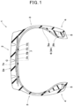
- FIG. 1 shows a tire meridian cross-sectional view of a tire 1 of the present embodiment in a normal state, including the rotation axis of the tire 1.
- the "normal state” is a state where: the tire 1 is fitted on a normal rim and adjusted to a normal internal pressure; and no load is applied to the tire 1.
- dimensions and the like of components of the tire 1 are values measured in the normal state.
- the "normal rim” is a rim that is defined, in a standard system including a standard on which the tire 1 is based, by the standard for each tire, and is, for example, the "standard rim” in the JATMA standard, the "Design Rim” in the TRA standard, or the “Measuring Rim” in the ETRTO standard.
- the "normal internal pressure” is an air pressure that is defined, in a standard system including a standard on which the tire 1 is based, by the standard for each tire, and is the “maximum air pressure” in the JATMA standard, the maximum value indicated in the table "TIRE LOAD LIMITS AT VARIOUS COLD INFLATION PRESSURES" in the TRA standard, or the “INFLATION PRESSURE” in the ETRTO standard.
- the tire 1 is suitably used, for example, as a heavy duty tire used for a truck or a bus.
- the tire 1 is not specified as a heavy duty tire, and can be applied to various tires including, for example, pneumatic tires such as a tire for a passenger car, a tire for a motorcycle, and a tire for racing, a non-pneumatic tire the interior of which is not filled with pressurized air, etc.
- the tire 1 of the present embodiment includes a tread portion 2 annularly extending, a pair of sidewall portions 3 extending on both sides of the tread portion 2, and a pair of bead portions 4 extending so as to be connected to the sidewall portions 3.
- the tire 1 also includes, for example, a toroidal carcass 6 extending on and between bead cores 5 of the pair of bead portions 4, and a belt layer 7 disposed outward of the carcass 6 in the tire radial direction and inward of the tread portion 2 in the tire radial direction.
- the carcass 6 is composed of, for example, one carcass ply 6A.
- the carcass ply 6A includes carcass cords and a topping rubber covering the carcass cords.
- the carcass cords are, for example, arranged so as to be tilted at an angle of 75 to 90° with respect to the tire circumferential direction.
- a to B indicates "not less than A and not greater than B".
- each carcass cord for example, a steel cord or a cord made of an organic fiber such as nylon, polyester, or rayon is suitably used.
- a steel cord is preferably used as each carcass cord.
- the carcass 6 may be composed of, for example, two or more carcass plies 6A.
- the carcass ply 6A includes, for example, a body portion 6a and turned-up portions 6b.
- the body portion 6a preferably extends from the tread portion 2 through each sidewall portion 3 to the bead core 5 of each bead portion 4.
- Each turned-up portion 6b is connected to the body portion 6a, is turned up around the bead core 5 from the inner side to the outer side in the tire axial direction, and extends outward in the tire radial direction.
- a so-called ultra-highly turned-up structure in which an end portion of each turned-up portion 6b extends to between the body portion 6a and the belt layer 7 may be employed.
- the belt layer 7 includes at least one belt ply.
- the belt layer 7 includes four belt plies 7A, 7B, 7C, and 7D.
- the belt layer 7 preferably includes two or more belt plies 7A, 7B, 7C, and 7D adjacent to each other in the tire radial direction.
- the multiple belt plies 7A, 7B, 7C, and 7D of such a belt layer 7 cooperate to improve the stiffness of the tread portion 2, and serve to improve the durability of the tire 1.
- the belt plies 7A, 7B, 7C, and 7D preferably have the same configuration. Such belt plies 7A, 7B, 7C, and 7D can be produced and managed as one belt ply 7a, so that the production cost can be reduced.
- the belt plies 7A, 7B, 7C, and 7D may have different configurations, for example.
- FIG. 2 is an enlarged cross-sectional view, of the tread portion 2, orthogonal to the longitudinal direction of belt cords 8.
- the belt ply 7a includes, for example, belt cords 8 arranged so as to be tilted relative to the tire circumferential direction, and a covering layer 9 covering the belt cords 8.
- Each belt cord 8 is preferably arranged so as to be tilted at an angle of 10 to 45° with respect to the tire circumferential direction.
- the same belt cords 8 and the same covering layer 9 are preferably included.
- the belt plies 7A, 7B, 7C, and 7D have different configurations, for example, at least either the belt cords 8 or the covering layer 9 is different.
- FIG. 3 is a schematic cross-sectional view, of the belt cord 8, orthogonal to the longitudinal direction of the belt cord 8.
- each belt cord 8 of the present embodiment has an N + M structure including N cores 10 and M sheaths 11.
- FIG. 3 shows a 1 + 8 structure including one core 10 and eight sheaths 11.
- Such a belt cord 8 can exhibit high stiffness and serves to improve the durability of the tire 1.
- Each sheath 11 may be, for example, a monofilament cord composed of a single filament, or a cord obtained by twisting a plurality of filaments together.
- a cord composed of a single filament and a cord obtained by twisting a plurality of filaments together may be combined and used.
- FIG. 4 is an enlarged view of the core 10 in FIG. 3 .
- the core 10 of the present embodiment has a cross-section having a flattened shape having a long diameter d1 and a short diameter d2.
- the core 10 has, for example, a substantially rectangular cross-section.
- Such a core 10 can flatten the entire belt cord 8 and can moderately alleviate the stiffness in the short diameter direction of the belt cord 8, thereby improving the ride comfort of the tire 1.
- the cross-sectional shape of the core 10 is not limited to such a mode, and may be, for example, an elliptical shape or a polygonal shape such as a hexagonal shape, as long as the cross-sectional shape is a flattened shape.
- the core 10 may be, for example, a monofilament cord composed of a single filament, or a cord obtained by twisting a plurality of filaments together.
- a monofilament cord is preferably used from the viewpoint of improving combined performance of ride comfort and durability.
- the long diameter d1 and the short diameter d2 of the core 10 are the largest straight line and the smallest straight line, respectively, among straight lines that pass through the center of a cross-section of the core cord and intersect the contour of the core cord. These axes can be obtained by performing measurement with calipers or the like being applied to the core 10, taken out from the belt cord 8, in a direction perpendicular to the longitudinal direction of the core 10.
- a value (d2/d1/L1) obtained by dividing a flatness ratio d2/d1 of the core 10 by a shortest distance L1 (mm) in the tire radial direction from a ground-contact surface 2a of the tread portion 2 to the center of the belt cord 8 in a tire meridian cross-section is not greater than 0.07 (1/mm).
- the tread portion 2 when the shortest distance L1 is smaller, the flatness ratio d2/d1 of the core 10 also becomes smaller, so that the stiffness in the short diameter direction of the belt cord 8 can be reduced. Accordingly, the tread portion 2 can improve followability to a road surface, so that the ride comfort of the tire 1 can be improved. In addition, such a tread portion 2 can also cause flexible movement in response to stretch of the sheaths 11 arranged around the core 10, so that the combined performance of the ride comfort and the durability of the tire 1 can be improved.
- the shortest distance L1 in the tire radial direction from the ground-contact surface 2a to the center of the belt cord 8 is the shortest distance from the outermost surface in the tire radial direction on a tire equator C to the center of the belt cord 8 of the belt ply 7a on the outermost side in the tire radial direction.
- the outermost surface in the tire radial direction on the tire equator C in the case where a groove is formed on the tire equator C is defined as the point of intersection of the tire equator C and a straight line connecting the outermost edges in the tire radial direction of both side walls of the groove on the tire equator C.
- the center of the belt cord 8 in the case where no belt cord 8 is present on the tire equator C is defined as the point of intersection of the tire equator C and a straight line connecting the centers of a pair of the belt cords 8 adjacent to the tire equator C.
- the shortest distance L1 is preferably a value measured in the normal state as described above, and can be obtained, for example, by a computer tomography method using X-rays.
- the shortest distance L1 may be measured, for example, in a simplified manner with the bead portions 4 in a cross-section portion cut out from a part of the tire 1 along a tire meridian, being matched with the width of the normal rim.
- Such a belt cord 8 can be easily stretched by increasing the length of each sheath 11 relative to the core 10, and flexibly follows deformation, so that the durability of the tire 1 can be improved. Therefore, the tire 1 of the present embodiment can have improved combined performance of ride comfort and durability.
- the value (d2/d1/L1) is more preferably not greater than 0.065 (1/mm) and further preferably not greater than 0.05 (1/mm).
- the lower limit of the value (d2/d1/L1) is not particularly limited, but the value (d2/d1/L1) is preferably not less than 0.01 (1/mm), more preferably not less than 0.02 (1/mm), and further preferably not less than 0.03 (1/mm).
- examples of the covering layer 9 of the belt ply 7a include a rubber composition and a thermoplastic elastomer composition.
- a rubber composition is preferably used from the viewpoint of forming a chemical network and firmly adhering the belt cord 8 and the covering layer 9.
- a thermoplastic elastomer composition is preferably used from the viewpoint of recyclability.
- the covering layer 9 is a rubber composition
- examples of the rubber component include isoprene-based rubbers, butadiene-based rubbers, styrene-butadiene rubber, and chloroprene rubber.
- the covering layer 9 preferably contains an isoprene-based rubber.
- examples of the isoprene-based rubber include natural rubber and synthetic isoprene rubber.
- the rubber composition of the covering layer 9 may contain a reinforcing filler, for example.
- a reinforcing filler examples include carbon black, silica, calcium carbonate, talc, alumina, clay, aluminum hydroxide, and mica.
- the amount of the filler per 100 parts by mass of the rubber component is preferably not less than 30 parts by mass.
- the amount of the filler is preferably not greater than 65 parts by mass.
- the rubber composition of the covering layer 9 preferably contains carbon black among the fillers.
- the amount of the carbon black per 100 parts by mass of the rubber component is preferably not less than 10 parts by mass.
- the amount of the carbon black is preferably not greater than 65 parts by mass.
- the carbon black is not particularly limited, and examples of the carbon black include: furnace black (furnace carbon black) such as SAF, ISAF, HAF, MAF, FEF, SRF, GPF, APF, FF, CF, SCF, and ECF; acetylene black (acetylene carbon black); thermal black (thermal carbon black) such as FT and MT; channel black (channel carbon black) such as EPC, MPC, and CC;
- the rubber composition of the covering layer 9 may contain a plasticizer, for example.
- the plasticizer include oils and resin components.
- the amount of the plasticizer per 100 parts by mass of the rubber component is preferably greater than 0.5 parts by mass and less than 10 parts by mass.
- the rubber composition of the covering layer 9 may contain cobalt element in the rubber, for example.
- cobalt element examples include organic acid cobalt salts such as cobalt stearate, cobalt naphthenate, cobalt neodecanoate, and cobalt boron neodecanoate.
- the rubber composition of the covering layer 9 may contain a curable resin component, for example.
- the curable resin component include modified resorcinol resins and modified phenol resins.
- the amount of the curable resin component per 100 parts by mass of the rubber component is preferably not less than 1 part by mass and more preferably not less than 2 parts by mass.
- the amount of the curable resin component is preferably not greater than 10 parts by mass and more preferably not greater than 8 parts by mass.
- the rubber composition of the covering layer 9 contains a curable resin component
- the rubber composition preferably also contains a resin curing agent.
- the resin curing agent include methylene donors such as hexamethylenetetramine (HMT), hexamethoxy methylol melamine (HMMM), and hexamethylol melamine pentamethyl ether (HMMPME).
- HMT hexamethylenetetramine
- HMMM hexamethoxy methylol melamine
- HMMPME hexamethylol melamine pentamethyl ether
- the amount of the resin curing agent per 100 parts by mass of the curable resin component is preferably not less than 5 parts by mass.
- the rubber composition of the covering layer 9 may contain, for example, an antioxidant, zinc oxide, sulfur, a vulcanization accelerator, a crosslinking agent, etc., as other components.
- the surface of the belt cord 8 is preferably plated.
- the type of the plating layer include a plating layer of two elements using copper and zinc and a plating layer of three elements using copper, zinc, and cobalt.
- an inter-center distance L2 between a pair of the belt cords 8 adjacent to each other in the width direction of the belt ply 7a is preferably not greater than 170% of a long diameter D1 of the belt cord 8.
- Such a belt ply 7a can increase the in-plane stiffness and suppress occurrence of belt looseness, so that the durability of the tire 1 can be improved.
- the inter-center distance L2 between the belt cords 8 is obtained as the average of the inter-center distances L2 between the five belt cords 8 on each of both sides in the tire axial direction of the tire equator C.
- the inter-center distance L2 in the case where the belt cord 8 is present on the tire equator C is preferably obtained as the average of the inter-center distances L2 between a total of eleven belt cords 8 including the belt cord 8 on the tire equator C and the five belt cords 8 on each of both sides.
- the inter-center distance L2 is preferably a value measured in the normal state as described above, and can be obtained, for example, by a computer tomography method using X-rays.
- the inter-center distance L2 may be measured, for example, in a simplified manner with the bead portions 4 in a cross-section portion cut out from a part of the tire 1 along a tire meridian, being matched with the width of the normal rim.
- FIG. 5 is a schematic cross-sectional view of the belt ply 7a.
- the inter-center distance L2 between the belt cords 8 in the case where the belt cords 8 are arranged so as to be tilted at an angle ⁇ 1 with respect to the tire circumferential direction can be obtained on the basis of the following equation (1) from an inter-center distance L2' between the belt cords 8 in a tire meridian cross-section.
- L 2 L 2 ′ cos ⁇ 1
- a thickness T of the belt ply 7a is preferably 160% to 200% of a short diameter D2 of the belt cord 8.
- a holding force by the belt ply 7a can be exerted while allowing stretch of the sheaths 11, so that the ride comfort and the durability of the tire 1 can be improved.
- the thickness T of the belt ply 7a is a thickness T of the belt ply 7a in the tire radial direction at the tire equator C in the normal state, and can be obtained, for example, by a computer tomography method using X-rays.
- the thickness T of the belt ply 7a may be measured, for example, in a simplified manner with the bead portions 4 in a cross-section portion cut out from a part of the tire 1 along a tire meridian, being matched with the width of the normal rim.
- a cross-sectional area S1 of the belt cord 8 within the belt ply 7a is preferably not greater than 30%, more preferably not greater than 29%, and further preferably not greater than 28%, of a cross-sectional area S2 of the belt ply 7a.
- the cross-sectional area S1 of the belt cord 8 is preferably not less than 20%, more preferably not less than 22%, and further preferably not less than 23%.
- Such a belt ply 7a can increase the in-plane stiffness and suppress occurrence of belt looseness, so that the durability of the tire 1 can be improved and the ride comfort of the tire 1 can also be improved.
- the cross-sectional area S2 of the belt ply 7a is obtained as the product (L2 ⁇ T) of the inter-center distance L2 between the belt cords 8 and the thickness T of the belt ply 7a.
- the cross-sectional area S1 of the belt cord 8 is obtained as the average of the cross-sectional areas S1 of the five belt cords 8 on each of both sides in the tire axial direction of the tire equator C.
- the cross-sectional area S1 in the case where the belt cord 8 is present on the tire equator C is preferably obtained as the average of the cross-sectional areas S1 of a total of eleven belt cords 8 including the belt cord 8 on the tire equator C and the five belt cords 8 on each of both sides.
- the long diameter D1 of the belt cord 8 is preferably not less than 1.10 mm, more preferably not less than 1.12 mm, and further preferably not less than 1.14 mm.
- the long diameter D1 of the belt cord 8 is preferably not greater than 1.80 mm, more preferably not greater than 1.70 mm, and further preferably not greater than 1.50 mm.
- the short diameter D2 of the belt cord 8 is preferably not less than 0.90 mm, more preferably not less than 0.94 mm, and further preferably not less than 0.97 mm.
- the short diameter D2 of the belt cord 8 is preferably not greater than 1.20 mm, more preferably not greater than 1.10 mm, and further preferably not greater than 1.00 mm. It should be noted that the short diameter D2 of the belt cord 8 is less than the long diameter D1 of the belt cord 8.
- Such a belt cord 8 can provide followability to a road surface while maintaining the stiffness in the width direction of the belt ply 7a, and serves to improve the combined performance of the ride comfort and the durability of the tire 1.
- the belt cords 8 are preferably arranged in the belt ply 7a such that the long diameter directions thereof form the same plane.
- a belt ply 7a can reduce the stiffness in the thickness direction while maintaining the stiffness in the width direction, so that the combined performance of the ride comfort and the durability of the tire 1 can be improved.
- the long diameter directions thereof forming the same plane means that the relative angles of the long diameter directions are within 10°.
- the flatness ratio d2/d1 of the core 10 is preferably not greater than 70%, more preferably not greater than 68%, and further preferably not greater than 65%.
- a core 10 reliably allows the belt cord 8 to be formed in a flattened shape, and serves to improve followability to a road surface while maintaining the stiffness in the width direction of the belt ply 7a.
- the lower limit of the flatness ratio d2/d1 of the core 10 is not particularly limited, but the flatness ratio d2/d1 of the core 10 is preferably not less than 30%, more preferably not less than 45%, and further preferably not less than 55%.
- the long diameter d1 of the core 10 is preferably not less than 0.30 mm, more preferably not less than 0.35 mm, and further preferably not less than 0.38 mm.
- the long diameter d1 of the core 10 is preferably not greater than 0.50 mm, more preferably not greater than 0.45 mm, and further preferably not greater than 0.43 mm.
- the short diameter d2 of the core 10 is preferably not less than 0.15 mm, more preferably not less than 0.20 mm, and further preferably not less than 0.22 mm.
- the short diameter d2 of the core 10 is preferably not greater than 0.42 mm, more preferably not greater than 0.40 mm, and further preferably not greater than 0.38 mm. It should be noted that the short diameter d2 of the core 10 is less than the long diameter d1 of the core 10.
- Such a core 10 achieves both stiffness in the long diameter direction and flexibility in the short diameter direction of the belt cord 8, and serves to improve the combined performance of the ride comfort and the durability of the tire 1.
- each corner portion of the substantially rectangular cross-section of the core 10 is formed, for example, in an arc shape.
- a radius r of the arc shape of each corner portion of the core 10 is preferably not less than 0.07 mm.
- the radius r of the arc shape of each corner portion of the core 10 is preferably not greater than 0.15 mm.
- FIG. 6 is a schematic cross-sectional view of a belt cord 12 of another embodiment.
- the belt cord 12 in FIG. 6 has a 3 + 12 structure including three cores 10 and twelve sheaths 11.
- the belt cords 8 and 12 each preferably include an untwisted core(s) 10 composed of one to three single steel wires.
- FIG. 3 shows a configuration including one core 10
- FIG. 6 shows a configuration including three cores 10.
- Such belt cords 8 and 12 serve to improve followability to a road surface while maintaining moderate stiffness.
- the belt cords 8 and 12 each preferably include five to twelve sheaths 11 each having a circular cross-sectional shape.
- FIG. 3 shows a configuration including eight sheaths 11, and
- FIG. 6 shows a configuration including twelve sheaths 11.
- Such belt cords 8 and 12 can cause stretch while maintaining moderate stiffness, and serve to improve the durability of the tire 1.
- the circular cross-sectional shape means that a cross-sectional shape orthogonal to the longitudinal direction of the sheath 11 is a circular shape, and refers to a shape having a flatness ratio of not greater than 1.05.
- a diameter d3 of each sheath 11 of the present embodiment is smaller than the long diameter d1 of the core 10.
- the diameter d3 of each sheath 11 is preferably equal to the short diameter d2 of the core 10 or larger than the short diameter d2.
- Such a sheath 11 serves to achieve both the stiffness and stretch of the belt cord 8 or 12.
- the diameter d3 of each sheath 11 is preferably 0.30 to 0.37 mm. When the diameter d3 of each sheath 11 is not less than 0.30 mm, good stiffness of the belt cord 8 or 12 can be maintained. When the diameter d3 of each sheath 11 is not greater than 0.37 mm, good stretch of the belt cord 8 or 12 can be maintained.
- the sheaths 11 are preferably twisted helically around the core(s) 10.
- the twisting pitch of the sheaths 11 is not particularly limited, but is preferably not less than the product of the diameter d3 of the sheath 11 and the number of the sheaths 11.
- the twisting pitch of the sheaths 11 is more preferably 1.05 to 4.00 times the product of the diameter d3 of the sheath 11 and the number of the sheaths 11.
- the cores 10 are preferably arranged such that the long diameter directions thereof form the same plane.
- Such cores 10 reliably allow the belt cord 12 to be formed in a flattened shape, and serve to reduce the weight of the belt ply 7a while maintaining the stiffness in the width direction of the belt ply 7a.
- FIG. 7 is a schematic cross-sectional view of a belt ply 7b of another embodiment.
- the cores 10 may be arranged such that the long diameter direction of the core 10 has an angle ⁇ 2 with respect to the width direction of the belt ply 7b.
- the long diameter directions of the cores 10 are preferably directed at an angle of 30° or less with respect to the width direction of the belt ply 7b.
- Such a belt ply 7b can exhibit the same effect as one in which the longitudinal directions of the belt cords 8 are directed so as to form the same plane, and the production process can be simplified, so that the production cost can be reduced.
- Tires (11R22.5 14PR) having the basic structure shown in FIG. 1 were produced as test tires based on specifications in Table 1 and Table 2. Using the produced test tires, ride comfort and durability were tested, and the combined performance thereof was evaluated.
- the production and test methods are as follows.
- each blending material shown below was prepared, and mixed with a 270-L Banbury mixer to obtain a covering layer rubber composition.
- belt cords shown in Table 1 and Table 2 were prepared, the prepared belt cords were arranged so as to have inter-center distances L2 between the belt cords shown in Table 1 and Table 2, and covering layers were press-bonded to the belt cords from above and below to obtain belt plies.
- the obtained belt plies were shaped together with inner liners, carcass plies, sidewall rubbers, bead apexes, bead cores, chafer rubbers, tread rubbers, etc., to obtain unvulcanized tires.
- the obtained unvulcanized tires were vulcanized at 160°C for 40 minutes to obtain test tires.
- the shortest distance L1 between the ground-contact surface of the tread portion and the belt cord center was adjusted by changing the thickness of the tread rubber.
- confirmation tires were produced with the same specifications as those of the test tires. Destructive inspection was performed on the confirmation tires, and the dimensions of each component of the test tires were confirmed from a tire meridian cross-section, a cross-section orthogonal to the longitudinal direction of the belt cords, and the arrangement state of the belt cords when the tread portion was peeled off.
- the produced test tires were mounted to all the wheels of test vehicles that were large trucks, and ride comfort when each vehicle was caused to run on a test course having a paved road including straight, curved, and meandering sections was evaluated on a 5 point scale with 5 being the maximum score through sensory evaluation by the test driver.
- the same test was made by 20 test drivers, and the total of scores by the test drivers was calculated.
- the results are represented as indexes with the total score of Comparative Example 1 being regarded as 100. A higher value indicates that the ride comfort is better.
- the produced test tires were fitted onto normal rims, adjusted to a normal internal pressure at an oxygen concentration of 90%, and thermally deteriorated in an oven at 70°C for 6 weeks. Then, each of the thermally deteriorated tires was mounted on a drum tester, and was caused to run based on the test conditions of the load/speed endurance test of the technical inspection standards and conformity inspection of the Ministry of Land, Infrastructure, Transport and Tourism until swelling occurred in the tread portion, and the running time was measured. The results are represented as indexes with the result of Comparative Example 1 being regarded as 100. A higher value indicates that the running time is longer and the durability is better.
- the tires of Examples have better ride comfort and durability than those of Comparative Examples, and also has better combined performance determined as the sum of the respective performances than that of Comparative Examples, so that it is confirmed that the tires of Examples have improved combined performance of ride comfort and durability.
- the present invention is as follows.
- a tire including a belt layer wherein the belt layer includes at least one belt ply in which belt cords are arranged, the belt cords each have an N + M structure including N core(s) and M sheaths, each core has a cross-section having a flattened shape having a long diameter d1 and a short diameter d2, and a value (d2/d1/L1) obtained by dividing a flatness ratio d2/d1 of the core by a shortest distance L1 (mm) in a tire radial direction from a ground-contact surface of a tread portion to a center of the belt cord in a tire meridian cross-section is not greater than 0.07 (1/mm).
- a thickness T of the belt ply is 160% to 200% of a short diameter D2 of the belt cord.
- an inter-center distance L2 between a pair of the belt cords adjacent to each other in a width direction of the belt ply is not greater than 170% of a long diameter D1 of the belt cord.
- a cross-sectional area of the belt cord is 20% to 30% of a cross-sectional area of the belt ply.
- the tire is a tire 1 including a belt layer 7.
- the belt layer 7 includes at least one belt ply 7a in which belt cords 8 are arranged.
- the belt cords 8 each have an N + M structure including N core(s) 10 and M sheaths 11.
- Each core 10 has a cross-section having a flattened shape having a long diameter d1 and a short diameter d2.
- a value (d2/d1/L1) obtained by dividing a flatness ratio d2/d1 of the core 10 by a shortest distance L1 (mm) in a tire radial direction from a ground-contact surface 2a of a tread portion 2 to a center of the belt cord 8 in a tire meridian cross-section is not greater than 0.07 (1/mm).
Landscapes
- Engineering & Computer Science (AREA)
- Mechanical Engineering (AREA)
- Tires In General (AREA)
- Ropes Or Cables (AREA)
Abstract
Description
- The present invention relates to a tire including a belt layer.
- Conventionally, a tire including a belt layer is known. For example,
Japanese Laid-Open Patent Publication No. 2015-171864 - However, in recent years, there has been strong demand for low fuel consumption performance, and there is a concern that ride comfort or durability may be reduced when weight reduction, which contributes significantly to improvement of low fuel consumption performance, is achieved.
- The present invention has been made in view of the above circumstances, and a main object of the present invention is to provide a tire that can have improved combined performance of ride comfort and durability.
- The present invention is directed to a tire including a belt layer, wherein the belt layer includes at least one belt ply in which belt cords are arranged, the belt cords each have an N + M structure including N core(s) and M sheaths, each core has a cross-section having a flattened shape having a long diameter d1 and a short diameter d2, and a value (d2/d1/L1) obtained by dividing a flatness ratio d2/d1 of the core by a shortest distance L1 (mm) in a tire radial direction from a ground-contact surface of a tread portion to a center of the belt cord in a tire meridian cross-section is not greater than 0.07 (1/mm).
- By having the above-described configuration, the tire of the present invention can have improved combined performance of ride comfort and durability.
-
-
FIG. 1 is a cross-sectional view showing a tire of an embodiment; -
FIG. 2 is an enlarged cross-sectional view of a tread portion of the embodiment; -
FIG. 3 is a schematic cross-sectional view of a belt cord; -
FIG. 4 is an enlarged view of a core inFIG. 3 ; -
FIG. 5 is a schematic cross-sectional view of a belt ply; -
FIG. 6 is a schematic cross-sectional view of a belt cord of another embodiment; and -
FIG. 7 is a schematic cross-sectional view of a belt ply of another embodiment. - Hereinafter, an embodiment of the present invention will be described in detail with reference to the drawings.
-
FIG. 1 shows a tire meridian cross-sectional view of atire 1 of the present embodiment in a normal state, including the rotation axis of thetire 1. Here, in the case where thetire 1 is a pneumatic tire, the "normal state" is a state where: thetire 1 is fitted on a normal rim and adjusted to a normal internal pressure; and no load is applied to thetire 1. Hereinafter, unless otherwise specified, dimensions and the like of components of thetire 1 are values measured in the normal state. - The "normal rim" is a rim that is defined, in a standard system including a standard on which the
tire 1 is based, by the standard for each tire, and is, for example, the "standard rim" in the JATMA standard, the "Design Rim" in the TRA standard, or the "Measuring Rim" in the ETRTO standard. - The "normal internal pressure" is an air pressure that is defined, in a standard system including a standard on which the
tire 1 is based, by the standard for each tire, and is the "maximum air pressure" in the JATMA standard, the maximum value indicated in the table "TIRE LOAD LIMITS AT VARIOUS COLD INFLATION PRESSURES" in the TRA standard, or the "INFLATION PRESSURE" in the ETRTO standard. - As shown in
FIG. 1 , thetire 1 is suitably used, for example, as a heavy duty tire used for a truck or a bus. Thetire 1 is not specified as a heavy duty tire, and can be applied to various tires including, for example, pneumatic tires such as a tire for a passenger car, a tire for a motorcycle, and a tire for racing, a non-pneumatic tire the interior of which is not filled with pressurized air, etc. - The
tire 1 of the present embodiment includes atread portion 2 annularly extending, a pair ofsidewall portions 3 extending on both sides of thetread portion 2, and a pair ofbead portions 4 extending so as to be connected to thesidewall portions 3. Thetire 1 also includes, for example, atoroidal carcass 6 extending on and betweenbead cores 5 of the pair ofbead portions 4, and abelt layer 7 disposed outward of thecarcass 6 in the tire radial direction and inward of thetread portion 2 in the tire radial direction. - The
carcass 6 is composed of, for example, onecarcass ply 6A. Thecarcass ply 6A includes carcass cords and a topping rubber covering the carcass cords. The carcass cords are, for example, arranged so as to be tilted at an angle of 75 to 90° with respect to the tire circumferential direction. Here, in the present specification, "A to B" indicates "not less than A and not greater than B". - As each carcass cord, for example, a steel cord or a cord made of an organic fiber such as nylon, polyester, or rayon is suitably used. Among them, in the case where the
tire 1 is used as a heavy duty tire, a steel cord is preferably used as each carcass cord. Thecarcass 6 may be composed of, for example, two ormore carcass plies 6A. - The
carcass ply 6A includes, for example, abody portion 6a and turned-upportions 6b. Thebody portion 6a preferably extends from thetread portion 2 through eachsidewall portion 3 to thebead core 5 of eachbead portion 4. Each turned-upportion 6b, for example, is connected to thebody portion 6a, is turned up around thebead core 5 from the inner side to the outer side in the tire axial direction, and extends outward in the tire radial direction. For thecarcass ply 6A, for example, a so-called ultra-highly turned-up structure in which an end portion of each turned-upportion 6b extends to between thebody portion 6a and thebelt layer 7 may be employed. - The
belt layer 7 includes at least one belt ply. In the present embodiment, thebelt layer 7 includes fourbelt plies belt layer 7 preferably includes two ormore belt plies multiple belt plies belt layer 7 cooperate to improve the stiffness of thetread portion 2, and serve to improve the durability of thetire 1. - The belt plies 7A, 7B, 7C, and 7D preferably have the same configuration.
Such belt plies belt ply 7a, so that the production cost can be reduced. The belt plies 7A, 7B, 7C, and 7D may have different configurations, for example. -
FIG. 2 is an enlarged cross-sectional view, of thetread portion 2, orthogonal to the longitudinal direction ofbelt cords 8. As shown inFIG. 2 , thebelt ply 7a includes, for example,belt cords 8 arranged so as to be tilted relative to the tire circumferential direction, and a covering layer 9 covering thebelt cords 8. Eachbelt cord 8 is preferably arranged so as to be tilted at an angle of 10 to 45° with respect to the tire circumferential direction. - In the case where the belt plies 7A, 7B, 7C, and 7D have the same configuration, the
same belt cords 8 and the same covering layer 9 are preferably included. On the other hand, in the case where the belt plies 7A, 7B, 7C, and 7D have different configurations, for example, at least either thebelt cords 8 or the covering layer 9 is different. -
FIG. 3 is a schematic cross-sectional view, of thebelt cord 8, orthogonal to the longitudinal direction of thebelt cord 8. As shown inFIG. 3 , eachbelt cord 8 of the present embodiment has an N + M structure includingN cores 10 andM sheaths 11.FIG. 3 shows a 1 + 8 structure including onecore 10 and eightsheaths 11. Such abelt cord 8 can exhibit high stiffness and serves to improve the durability of thetire 1. - Each
sheath 11 may be, for example, a monofilament cord composed of a single filament, or a cord obtained by twisting a plurality of filaments together. In addition, as eachsheath 11, for example, a cord composed of a single filament and a cord obtained by twisting a plurality of filaments together may be combined and used. -
FIG. 4 is an enlarged view of thecore 10 inFIG. 3 . As shown inFIG. 3 andFIG. 4 , thecore 10 of the present embodiment has a cross-section having a flattened shape having a long diameter d1 and a short diameter d2. Thecore 10 has, for example, a substantially rectangular cross-section. Such acore 10 can flatten theentire belt cord 8 and can moderately alleviate the stiffness in the short diameter direction of thebelt cord 8, thereby improving the ride comfort of thetire 1. The cross-sectional shape of thecore 10 is not limited to such a mode, and may be, for example, an elliptical shape or a polygonal shape such as a hexagonal shape, as long as the cross-sectional shape is a flattened shape. - The
core 10 may be, for example, a monofilament cord composed of a single filament, or a cord obtained by twisting a plurality of filaments together. As thecore 10, a monofilament cord is preferably used from the viewpoint of improving combined performance of ride comfort and durability. - The long diameter d1 and the short diameter d2 of the core 10 are the largest straight line and the smallest straight line, respectively, among straight lines that pass through the center of a cross-section of the core cord and intersect the contour of the core cord. These axes can be obtained by performing measurement with calipers or the like being applied to the
core 10, taken out from thebelt cord 8, in a direction perpendicular to the longitudinal direction of thecore 10. - As shown in
FIG. 2 and FIG. 3 , in the present embodiment, a value (d2/d1/L1) obtained by dividing a flatness ratio d2/d1 of the core 10 by a shortest distance L1 (mm) in the tire radial direction from a ground-contact surface 2a of thetread portion 2 to the center of thebelt cord 8 in a tire meridian cross-section is not greater than 0.07 (1/mm). - In such a
tread portion 2, when the shortest distance L1 is smaller, the flatness ratio d2/d1 of the core 10 also becomes smaller, so that the stiffness in the short diameter direction of thebelt cord 8 can be reduced. Accordingly, thetread portion 2 can improve followability to a road surface, so that the ride comfort of thetire 1 can be improved. In addition, such atread portion 2 can also cause flexible movement in response to stretch of thesheaths 11 arranged around thecore 10, so that the combined performance of the ride comfort and the durability of thetire 1 can be improved. - Here, the shortest distance L1 in the tire radial direction from the ground-
contact surface 2a to the center of thebelt cord 8 is the shortest distance from the outermost surface in the tire radial direction on a tire equator C to the center of thebelt cord 8 of the belt ply 7a on the outermost side in the tire radial direction. - The outermost surface in the tire radial direction on the tire equator C in the case where a groove is formed on the tire equator C is defined as the point of intersection of the tire equator C and a straight line connecting the outermost edges in the tire radial direction of both side walls of the groove on the tire equator C. In addition, the center of the
belt cord 8 in the case where nobelt cord 8 is present on the tire equator C is defined as the point of intersection of the tire equator C and a straight line connecting the centers of a pair of thebelt cords 8 adjacent to the tire equator C. - The shortest distance L1 is preferably a value measured in the normal state as described above, and can be obtained, for example, by a computer tomography method using X-rays. The shortest distance L1 may be measured, for example, in a simplified manner with the
bead portions 4 in a cross-section portion cut out from a part of thetire 1 along a tire meridian, being matched with the width of the normal rim. - Such a
belt cord 8 can be easily stretched by increasing the length of eachsheath 11 relative to thecore 10, and flexibly follows deformation, so that the durability of thetire 1 can be improved. Therefore, thetire 1 of the present embodiment can have improved combined performance of ride comfort and durability. - From such a viewpoint, the value (d2/d1/L1) is more preferably not greater than 0.065 (1/mm) and further preferably not greater than 0.05 (1/mm). The lower limit of the value (d2/d1/L1) is not particularly limited, but the value (d2/d1/L1) is preferably not less than 0.01 (1/mm), more preferably not less than 0.02 (1/mm), and further preferably not less than 0.03 (1/mm).
- As a more preferable mode, examples of the covering layer 9 of the
belt ply 7a include a rubber composition and a thermoplastic elastomer composition. As the covering layer 9, a rubber composition is preferably used from the viewpoint of forming a chemical network and firmly adhering thebelt cord 8 and the covering layer 9. As the covering layer 9, a thermoplastic elastomer composition is preferably used from the viewpoint of recyclability. - In the case where the covering layer 9 is a rubber composition, examples of the rubber component include isoprene-based rubbers, butadiene-based rubbers, styrene-butadiene rubber, and chloroprene rubber. From the viewpoint of the adhesion to the
belt cord 8, the covering layer 9 preferably contains an isoprene-based rubber. Examples of the isoprene-based rubber include natural rubber and synthetic isoprene rubber. - The rubber composition of the covering layer 9 may contain a reinforcing filler, for example. Examples of the filler include carbon black, silica, calcium carbonate, talc, alumina, clay, aluminum hydroxide, and mica.
- From the viewpoint of durability, the amount of the filler per 100 parts by mass of the rubber component is preferably not less than 30 parts by mass. On the other hand, from the viewpoint of heat generation properties, as for the upper limit of the amount of the filler, the amount of the filler is preferably not greater than 65 parts by mass.
- The rubber composition of the covering layer 9 preferably contains carbon black among the fillers. From the viewpoint of durability, the amount of the carbon black per 100 parts by mass of the rubber component is preferably not less than 10 parts by mass. On the other hand, from the viewpoint of heat generation properties, as for the upper limit of the amount of the carbon black, the amount of the carbon black is preferably not greater than 65 parts by mass.
- The carbon black is not particularly limited, and examples of the carbon black include: furnace black (furnace carbon black) such as SAF, ISAF, HAF, MAF, FEF, SRF, GPF, APF, FF, CF, SCF, and ECF; acetylene black (acetylene carbon black); thermal black (thermal carbon black) such as FT and MT; channel black (channel carbon black) such as EPC, MPC, and CC; and graphite. One of these carbon blacks may be used alone, or two or more of these carbon blacks may be used in combination.
- The rubber composition of the covering layer 9 may contain a plasticizer, for example. Examples of the plasticizer include oils and resin components. The amount of the plasticizer per 100 parts by mass of the rubber component is preferably greater than 0.5 parts by mass and less than 10 parts by mass.
- From the viewpoint of adhesion, the rubber composition of the covering layer 9 may contain cobalt element in the rubber, for example. Examples of compounds containing cobalt element include organic acid cobalt salts such as cobalt stearate, cobalt naphthenate, cobalt neodecanoate, and cobalt boron neodecanoate.
- From the viewpoint of adhesion, the rubber composition of the covering layer 9 may contain a curable resin component, for example. Examples of the curable resin component include modified resorcinol resins and modified phenol resins. The amount of the curable resin component per 100 parts by mass of the rubber component is preferably not less than 1 part by mass and more preferably not less than 2 parts by mass. On the other hand, as for the upper limit of the amount of the curable resin component, the amount of the curable resin component is preferably not greater than 10 parts by mass and more preferably not greater than 8 parts by mass.
- In the case where the rubber composition of the covering layer 9 contains a curable resin component, the rubber composition preferably also contains a resin curing agent. Examples of the resin curing agent include methylene donors such as hexamethylenetetramine (HMT), hexamethoxy methylol melamine (HMMM), and hexamethylol melamine pentamethyl ether (HMMPME). The amount of the resin curing agent per 100 parts by mass of the curable resin component is preferably not less than 5 parts by mass.
- The rubber composition of the covering layer 9 may contain, for example, an antioxidant, zinc oxide, sulfur, a vulcanization accelerator, a crosslinking agent, etc., as other components.
- From the viewpoint of adhesion to the covering layer 9, the surface of the
belt cord 8 is preferably plated. Examples of the type of the plating layer include a plating layer of two elements using copper and zinc and a plating layer of three elements using copper, zinc, and cobalt. By forming a plating layer of three elements on thebelt cord 8, thebelt cord 8 can have further improved adhesion to the covering layer 9. - In a cross-section orthogonal to the longitudinal direction of the
belt cords 8, an inter-center distance L2 between a pair of thebelt cords 8 adjacent to each other in the width direction of thebelt ply 7a is preferably not greater than 170% of a long diameter D1 of thebelt cord 8. Such abelt ply 7a can increase the in-plane stiffness and suppress occurrence of belt looseness, so that the durability of thetire 1 can be improved. - Here, the inter-center distance L2 between the
belt cords 8 is obtained as the average of the inter-center distances L2 between the fivebelt cords 8 on each of both sides in the tire axial direction of the tire equator C. The inter-center distance L2 in the case where thebelt cord 8 is present on the tire equator C is preferably obtained as the average of the inter-center distances L2 between a total of elevenbelt cords 8 including thebelt cord 8 on the tire equator C and the fivebelt cords 8 on each of both sides. - The inter-center distance L2 is preferably a value measured in the normal state as described above, and can be obtained, for example, by a computer tomography method using X-rays. The inter-center distance L2 may be measured, for example, in a simplified manner with the
bead portions 4 in a cross-section portion cut out from a part of thetire 1 along a tire meridian, being matched with the width of the normal rim. -
FIG. 5 is a schematic cross-sectional view of thebelt ply 7a. As shown inFIG. 5 , the inter-center distance L2 between thebelt cords 8 in the case where thebelt cords 8 are arranged so as to be tilted at an angle θ1 with respect to the tire circumferential direction can be obtained on the basis of the following equation (1) from an inter-center distance L2' between thebelt cords 8 in a tire meridian cross-section.
- As shown in
FIG. 2 , a thickness T of thebelt ply 7a is preferably 160% to 200% of a short diameter D2 of thebelt cord 8. In such abelt ply 7a, since sufficient covering with the covering layer 9 is achieved, a holding force by thebelt ply 7a can be exerted while allowing stretch of thesheaths 11, so that the ride comfort and the durability of thetire 1 can be improved. - Here, the thickness T of the
belt ply 7a is a thickness T of thebelt ply 7a in the tire radial direction at the tire equator C in the normal state, and can be obtained, for example, by a computer tomography method using X-rays. The thickness T of thebelt ply 7a may be measured, for example, in a simplified manner with thebead portions 4 in a cross-section portion cut out from a part of thetire 1 along a tire meridian, being matched with the width of the normal rim. - In a cross-section orthogonal to the longitudinal direction of the
belt cords 8, a cross-sectional area S1 of thebelt cord 8 within thebelt ply 7a is preferably not greater than 30%, more preferably not greater than 29%, and further preferably not greater than 28%, of a cross-sectional area S2 of thebelt ply 7a. - As for the lower limit of the cross-sectional area S1 of the
belt cord 8 with respect to the cross-sectional area S2 of thebelt ply 7a, the cross-sectional area S1 is preferably not less than 20%, more preferably not less than 22%, and further preferably not less than 23%. Such abelt ply 7a can increase the in-plane stiffness and suppress occurrence of belt looseness, so that the durability of thetire 1 can be improved and the ride comfort of thetire 1 can also be improved. - Here, the cross-sectional area S2 of the
belt ply 7a is obtained as the product (L2×T) of the inter-center distance L2 between thebelt cords 8 and the thickness T of thebelt ply 7a. In addition, the cross-sectional area S1 of thebelt cord 8 is obtained as the average of the cross-sectional areas S1 of the fivebelt cords 8 on each of both sides in the tire axial direction of the tire equator C. The cross-sectional area S1 in the case where thebelt cord 8 is present on the tire equator C is preferably obtained as the average of the cross-sectional areas S1 of a total of elevenbelt cords 8 including thebelt cord 8 on the tire equator C and the fivebelt cords 8 on each of both sides. - The long diameter D1 of the
belt cord 8 is preferably not less than 1.10 mm, more preferably not less than 1.12 mm, and further preferably not less than 1.14 mm. In addition, the long diameter D1 of thebelt cord 8 is preferably not greater than 1.80 mm, more preferably not greater than 1.70 mm, and further preferably not greater than 1.50 mm. - The short diameter D2 of the
belt cord 8 is preferably not less than 0.90 mm, more preferably not less than 0.94 mm, and further preferably not less than 0.97 mm. In addition, the short diameter D2 of thebelt cord 8 is preferably not greater than 1.20 mm, more preferably not greater than 1.10 mm, and further preferably not greater than 1.00 mm. It should be noted that the short diameter D2 of thebelt cord 8 is less than the long diameter D1 of thebelt cord 8. - Such a
belt cord 8 can provide followability to a road surface while maintaining the stiffness in the width direction of thebelt ply 7a, and serves to improve the combined performance of the ride comfort and the durability of thetire 1. - The
belt cords 8 are preferably arranged in thebelt ply 7a such that the long diameter directions thereof form the same plane. Such abelt ply 7a can reduce the stiffness in the thickness direction while maintaining the stiffness in the width direction, so that the combined performance of the ride comfort and the durability of thetire 1 can be improved. Here, the long diameter directions thereof forming the same plane means that the relative angles of the long diameter directions are within 10°. - As shown in
FIG. 3 andFIG. 4 , the flatness ratio d2/d1 of thecore 10 is preferably not greater than 70%, more preferably not greater than 68%, and further preferably not greater than 65%. Such a core 10 reliably allows thebelt cord 8 to be formed in a flattened shape, and serves to improve followability to a road surface while maintaining the stiffness in the width direction of thebelt ply 7a. The lower limit of the flatness ratio d2/d1 of thecore 10 is not particularly limited, but the flatness ratio d2/d1 of thecore 10 is preferably not less than 30%, more preferably not less than 45%, and further preferably not less than 55%. - The long diameter d1 of the
core 10 is preferably not less than 0.30 mm, more preferably not less than 0.35 mm, and further preferably not less than 0.38 mm. In addition, the long diameter d1 of thecore 10 is preferably not greater than 0.50 mm, more preferably not greater than 0.45 mm, and further preferably not greater than 0.43 mm. - The short diameter d2 of the
core 10 is preferably not less than 0.15 mm, more preferably not less than 0.20 mm, and further preferably not less than 0.22 mm. In addition, the short diameter d2 of thecore 10 is preferably not greater than 0.42 mm, more preferably not greater than 0.40 mm, and further preferably not greater than 0.38 mm. It should be noted that the short diameter d2 of thecore 10 is less than the long diameter d1 of thecore 10. - Such a
core 10 achieves both stiffness in the long diameter direction and flexibility in the short diameter direction of thebelt cord 8, and serves to improve the combined performance of the ride comfort and the durability of thetire 1. - As shown in
FIG. 4 , each corner portion of the substantially rectangular cross-section of thecore 10 is formed, for example, in an arc shape. A radius r of the arc shape of each corner portion of thecore 10 is preferably not less than 0.07 mm. In addition, the radius r of the arc shape of each corner portion of thecore 10 is preferably not greater than 0.15 mm. Such acore 10 has no risk of damaging thesheaths 11, so that the durability of thetire 1 can be improved. -
FIG. 6 is a schematic cross-sectional view of abelt cord 12 of another embodiment. Thebelt cord 12 inFIG. 6 has a 3 + 12 structure including threecores 10 and twelvesheaths 11. As shown inFIG. 3 andFIG. 6 , thebelt cords FIG. 3 shows a configuration including onecore 10, andFIG. 6 shows a configuration including threecores 10.Such belt cords - The
belt cords sheaths 11 each having a circular cross-sectional shape.FIG. 3 shows a configuration including eightsheaths 11, andFIG. 6 shows a configuration including twelvesheaths 11.Such belt cords tire 1. Here, the circular cross-sectional shape means that a cross-sectional shape orthogonal to the longitudinal direction of thesheath 11 is a circular shape, and refers to a shape having a flatness ratio of not greater than 1.05. - A diameter d3 of each
sheath 11 of the present embodiment is smaller than the long diameter d1 of thecore 10. The diameter d3 of eachsheath 11 is preferably equal to the short diameter d2 of the core 10 or larger than the short diameter d2. Such asheath 11 serves to achieve both the stiffness and stretch of thebelt cord - The diameter d3 of each
sheath 11 is preferably 0.30 to 0.37 mm. When the diameter d3 of eachsheath 11 is not less than 0.30 mm, good stiffness of thebelt cord sheath 11 is not greater than 0.37 mm, good stretch of thebelt cord - In each of the
belt cords sheaths 11 are preferably twisted helically around the core(s) 10. The twisting pitch of thesheaths 11 is not particularly limited, but is preferably not less than the product of the diameter d3 of thesheath 11 and the number of thesheaths 11. The twisting pitch of thesheaths 11 is more preferably 1.05 to 4.00 times the product of the diameter d3 of thesheath 11 and the number of thesheaths 11. - In the case where a plurality of
cores 10 are included as shown inFIG. 6 , thecores 10 are preferably arranged such that the long diameter directions thereof form the same plane.Such cores 10 reliably allow thebelt cord 12 to be formed in a flattened shape, and serve to reduce the weight of thebelt ply 7a while maintaining the stiffness in the width direction of thebelt ply 7a. -
FIG. 7 is a schematic cross-sectional view of abelt ply 7b of another embodiment. As shown inFIG. 7 , in a cross-section orthogonal to the longitudinal direction of thebelt cords 8, in thebelt ply 7b, for example, thecores 10 may be arranged such that the long diameter direction of thecore 10 has an angle θ2 with respect to the width direction of thebelt ply 7b. In this case, the long diameter directions of thecores 10 are preferably directed at an angle of 30° or less with respect to the width direction of thebelt ply 7b. - Such a
belt ply 7b can exhibit the same effect as one in which the longitudinal directions of thebelt cords 8 are directed so as to form the same plane, and the production process can be simplified, so that the production cost can be reduced. - Although the particularly preferred embodiments of the present invention have been described in detail above, the present invention is not limited to the above-described embodiments, and various modifications can be made to implement the present invention.
- Tires (11R22.5 14PR) having the basic structure shown in
FIG. 1 were produced as test tires based on specifications in Table 1 and Table 2. Using the produced test tires, ride comfort and durability were tested, and the combined performance thereof was evaluated. The production and test methods are as follows. - First, each blending material shown below was prepared, and mixed with a 270-L Banbury mixer to obtain a covering layer rubber composition.
-
- (a) Rubber component: natural rubber
: 100 parts by mass - (b) Blending Material Other Than Rubber Component
- (i) Carbon black: SHOBLACK N326 manufactured by Cabot Japan K.K.
: 40 parts by mass - (ii) Carbon black: SHOBLACK N550 manufactured by Cabot Japan K.K.
: 15 parts by mass - (iii) Curable resin component: SUMIKANOL 620 manufactured by Taoka Chemical Co., Ltd.
: 5 parts by mass - (iv) Resin curing agent: SUMIKANOL 507 manufactured by Taoka Chemical Co., Ltd.
: 1.5 parts by mass - (v) Organic acid cobalt salt: DICNATE NBC-2 manufactured by DIC Corporation
: 1 part by mass - (vi) Antioxidant: NOCRAC 6C manufactured by Ouchi Shinko Chemical Industrial Co., Ltd.
: 0.5 parts by mass - (vii) Antioxidant: ANTAGE RD manufactured by Kawaguchi Chemical Industry Co., Ltd.
: 1 part by mass - (viii) Zinc oxide: Zinc Oxide Type-1 manufactured by Mitsui Mining & Smelting Co., Ltd.
: 10 parts by mass - (ix) Sulfur: powdery sulfur manufactured by Tsurumi Chemical Industry Co., Ltd.
: 7 parts by mass - (x) Vulcanization accelerator: NOCCELER DZ manufactured by Ouchi Shinko Chemical Industrial Co., Ltd.
: 1.2 parts by mass - (xi) Crosslinking agent: DURALINK HTS manufactured by Flexsys
: 1.5 parts by mass
- (i) Carbon black: SHOBLACK N326 manufactured by Cabot Japan K.K.
- Next, belt cords shown in Table 1 and Table 2 were prepared, the prepared belt cords were arranged so as to have inter-center distances L2 between the belt cords shown in Table 1 and Table 2, and covering layers were press-bonded to the belt cords from above and below to obtain belt plies.
- The obtained belt plies were shaped together with inner liners, carcass plies, sidewall rubbers, bead apexes, bead cores, chafer rubbers, tread rubbers, etc., to obtain unvulcanized tires. The obtained unvulcanized tires were vulcanized at 160°C for 40 minutes to obtain test tires. In each of the produced test tires, the shortest distance L1 between the ground-contact surface of the tread portion and the belt cord center was adjusted by changing the thickness of the tread rubber.
- Moreover, in addition to the test tires used for the tests, confirmation tires were produced with the same specifications as those of the test tires. Destructive inspection was performed on the confirmation tires, and the dimensions of each component of the test tires were confirmed from a tire meridian cross-section, a cross-section orthogonal to the longitudinal direction of the belt cords, and the arrangement state of the belt cords when the tread portion was peeled off.
- The produced test tires were mounted to all the wheels of test vehicles that were large trucks, and ride comfort when each vehicle was caused to run on a test course having a paved road including straight, curved, and meandering sections was evaluated on a 5 point scale with 5 being the maximum score through sensory evaluation by the test driver. The same test was made by 20 test drivers, and the total of scores by the test drivers was calculated. The results are represented as indexes with the total score of Comparative Example 1 being regarded as 100. A higher value indicates that the ride comfort is better.
- The produced test tires were fitted onto normal rims, adjusted to a normal internal pressure at an oxygen concentration of 90%, and thermally deteriorated in an oven at 70°C for 6 weeks. Then, each of the thermally deteriorated tires was mounted on a drum tester, and was caused to run based on the test conditions of the load/speed endurance test of the technical inspection standards and conformity inspection of the Ministry of Land, Infrastructure, Transport and Tourism until swelling occurred in the tread portion, and the running time was measured. The results are represented as indexes with the result of Comparative Example 1 being regarded as 100. A higher value indicates that the running time is longer and the durability is better.
- Combined performance of ride comfort and durability was evaluated based on the evaluation results of ride comfort and the evaluation results of durability. The results are represented as the sum of the index of ride comfort and the index of durability. A higher value indicates that the combined performance of ride comfort and durability is better.
- The results of the tests are shown in Table 1 and Table 2.
[Table 1] Comp. Ex. 1 Comp. Ex. 2 Comp. Ex. 3 Comp. Ex. 4 Comp. Ex. 5 Ex. 1 Ex. 2 Belt cord structure 1×3+6 1×2+7 1+8 1+8 1+8 1+8 2+7 Number of cores 3 2 1 1 1 1 2 Number of sheaths 6 7 8 8 8 8 7 Core long diameter dl (mm) 0.20 0.37 0.35 0.50 0.45 0.45 0.45 Core short diameter d2 (mm) 0.20 0.37 0.35 0.45 0.30 0.30 0.30 Sheath diameter d3 (mm) 0.35 0.37 0.35 0.35 0.35 0.35 0.37 Belt cord long diameter D1 (mm) 1.10 1.42 1.05 1.20 1.15 1.15 1.64 Belt cord short diameter D2 (mm) 1.10 1.42 1.05 1.15 1.00 1.00 1.04 Belt cord angle θ1 (°) 35 35 35 35 35 35 35 Shortest distance L1 between ground-contact surface and belt cord center (mm) 10 10 10 10 8 10 10 Inter-center distance L2 between belt cords (mm) 1.92 1.92 1.92 1.92 1.92 1.92 1.92 Inter-center distance L2' between belt cords (mm) 2.35 2.35 2.35 2.35 2.35 2.35 2.35 Belt ply thickness T (mm) 1.75 2.07 1.70 1.65 1.65 1.65 1.69 Core maximum tilt angle θ2 (°) 0 0 0 10 10 35 35 Core flatness ratio d2/dl (%) 100 100 100 90 67 67 67 Value d2/d1/L1 (1/mm) 0.100 0.100 0.100 0.090 0.083 0.067 0.067 Value L2/D1 (%) 175 135 183 160 167 167 117 Value T/D2 (%) 159 146 162 143 165 165 163 Cross-sectional area ratio S1/S2 (%) 20 24 26 31 29 29 31 Ride comfort (index) 100 96 95 98 100 108 106 Durability (index) 100 98 95 100 96 108 110 Combined performance (total value) 200 194 190 198 196 216 216 [Table 2] Ex. 3 Ex. 4 Ex. 5 Ex. 6 Ex. 7 Ex. 8 Belt cord structure 3+9 1+8 1+8 1+8 1+8 1+8 Number of cores 3 1 1 1 1 1 Number of sheaths 9 8 8 8 8 8 Core long diameter dl (mm) 0.40 0.45 0.40 0.45 0.45 0.45 Core short diameter d2 (mm) 0.25 0.30 0.25 0.30 0.30 0.30 Sheath diameter d3 (mm) 0.30 0.35 0.35 0.35 0.35 0.35 Belt cord long diameter D1 (mm) 1.80 1.15 1.10 1.15 1.15 1.15 Belt cord short diameter D2 (mm) 0.85 1.00 0.95 1.00 1.00 1.00 Belt cord angle θ1 (°) 35 35 35 45 28 35 Shortest distance L1 between ground-contact surface and belt cord center (mm) 10 14 14 10 10 10 Inter-center distance L2 between belt cords (mm) 1.92 1.92 1.92 1.92 1.92 1.92 Inter-center distance L2' between belt cords (mm) 2.35 2.35 2.35 2.72 2.18 2.35 Belt ply thickness T (mm) 1.50 1.65 1.65 1.65 1.65 2.20 Core maximum tilt angle θ2 (°) 35 35 35 35 28 35 Core flatness ratio d2/dl (%) 63 67 63 67 67 67 Value d2/d1/L1 (1/mm) 0.063 0.048 0.045 0.067 0.067 0.067 Value L2/D1 (%) 107 167 175 167 167 167 Value T/D2 (%) 176 165 174 165 165 220 Cross-sectional area ratio S1/S2 (%) 32 29 27 29 29 21 Ride comfort (index) 112 114 118 106 106 106 Durability (index) 108 118 122 104 112 102 Combined performance (total value) 220 232 240 210 218 208 - As a result of the tests, the tires of Examples have better ride comfort and durability than those of Comparative Examples, and also has better combined performance determined as the sum of the respective performances than that of Comparative Examples, so that it is confirmed that the tires of Examples have improved combined performance of ride comfort and durability.
- The present invention is as follows.
- A tire including a belt layer, wherein the belt layer includes at least one belt ply in which belt cords are arranged, the belt cords each have an N + M structure including N core(s) and M sheaths, each core has a cross-section having a flattened shape having a long diameter d1 and a short diameter d2, and a value (d2/d1/L1) obtained by dividing a flatness ratio d2/d1 of the core by a shortest distance L1 (mm) in a tire radial direction from a ground-contact surface of a tread portion to a center of the belt cord in a tire meridian cross-section is not greater than 0.07 (1/mm).
- The tire according to
Present Invention 1, wherein the flatness ratio d2/d1 of the core is not greater than 70%. - The tire according to
Present Invention - The tire according to any one of
Present Inventions 1 to 3, wherein the belt cords each include the untwisted core composed of one to three single steel wires. - The tire according to any one of
Present Inventions 1 to 4, wherein the belt cords each include five to twelve of the sheaths each having a circular cross-sectional shape. - The tire according to any one of
Present Inventions 1 to 5, wherein the belt layer includes two or more of the belt plies adjacent to each other in the tire radial direction. - The tire according to any one of
Present Inventions 1 to 6, wherein a thickness T of the belt ply is 160% to 200% of a short diameter D2 of the belt cord. - The tire according to any one of
Present Inventions 1 to 7, wherein, in a cross-section orthogonal to a longitudinal direction of the belt cords, an inter-center distance L2 between a pair of the belt cords adjacent to each other in a width direction of the belt ply is not greater than 170% of a long diameter D1 of the belt cord. - The tire according to any one of
Present Inventions 1 to 8, wherein, in a cross-section orthogonal to the longitudinal direction of the belt cords, a cross-sectional area of the belt cord is 20% to 30% of a cross-sectional area of the belt ply. - The tire according to any one of
Present Inventions 1 to 9, wherein, in a cross-section orthogonal to the longitudinal direction of the belt cords, a long diameter direction of each core is directed at an angle of 30° or less with respect to the width direction of the belt ply. -
- 1. Tire
- 2. Tread portion
- 2a. Ground-contact surface
- 3. Sidewall portions
- 4. Bead portions
- 5. Bead cores
- 6. Carcass
- 7. Belt layer
- 7A,7B,7C,7D,7a,7b. Belt ply
- 8. Belt cords
- 9. Covering layer
- 10. Core
- 11. Sheaths
- 12. Belt cords
- Provided is a tire that can have improved combined performance of ride comfort and durability. The tire is a
tire 1 including abelt layer 7. Thebelt layer 7 includes at least onebelt ply 7a in whichbelt cords 8 are arranged. Thebelt cords 8 each have an N + M structure including N core(s) 10 andM sheaths 11. Eachcore 10 has a cross-section having a flattened shape having a long diameter d1 and a short diameter d2. A value (d2/d1/L1) obtained by dividing a flatness ratio d2/d1 of the core 10 by a shortest distance L1 (mm) in a tire radial direction from a ground-contact surface 2a of atread portion 2 to a center of thebelt cord 8 in a tire meridian cross-section is not greater than 0.07 (1/mm).
Claims (10)
- A tire (1) comprising a belt layer (7), whereinthe belt layer (7) includes at least one belt ply (7A, 7B, 7C, 7D, 7a, 7b) in which belt cords (8) are arranged,the belt cords (8, 12) each have an N + M structure including N core(s) (10) and M sheaths (11),each core (10) has a cross-section having a flattened shape having a long diameter d1 and a short diameter d2, anda value (d2/d1/L1) obtained by dividing a flatness ratio d2/d1 of the core (10) by a shortest distance L1 (mm) in a tire radial direction from a ground-contact surface (2a) of a tread portion (2) to a center of the belt cord (8, 12) in a tire meridian cross-section is not greater than 0.07 (1/mm).
- The tire (1) according to claim 1, wherein the flatness ratio d2/d1 of the core (10) is not greater than 70%.
- The tire (1) according to claim 1 or 2, wherein the short diameter d2 of the core (10) is 0.15 to 0.42 mm.
- The tire (1) according to any one of claims 1 to 3, wherein the belt cords (8, 12) each include the untwisted core (10) composed of one to three single steel wires.
- The tire (1) according to any one of claims 1 to 4, wherein the belt cords (8, 12) each include five to twelve of the sheaths (11) each having a circular cross-sectional shape.
- The tire (1) according to any one of claims 1 to 5, wherein the belt layer (7) includes two or more of the belt plies (7a) adjacent to each other in the tire radial direction.
- The tire (1) according to any one of claims 1 to 6, wherein a thickness T of the belt ply (7a) is 160% to 200% of a short diameter D2 of the belt cord (8).
- The tire (1) according to any one of claims 1 to 7, wherein, in a cross-section orthogonal to a longitudinal direction of the belt cords (8), an inter-center distance L2 between a pair of the belt cords (8) adjacent to each other in a width direction of the belt ply (7a) is not greater than 170% of a long diameter D1 of the belt cord (8).
- The tire (1) according to any one of claims 1 to 8, wherein, in a cross-section orthogonal to the longitudinal direction of the belt cords (8), a cross-sectional area (S1) of the belt cord (8) is 20% to 30% of a cross-sectional area (S2) of the belt ply (7a).
- The tire (1) according to any one of claims 1 to 9, wherein, in a cross-section orthogonal to the longitudinal direction of the belt cords (8), a long diameter direction of each core (10) is directed at an angle of 30° or less with respect to the width direction of the belt ply (7b).
Applications Claiming Priority (1)
| Application Number | Priority Date | Filing Date | Title |
|---|---|---|---|
| JP2021209801A JP2023094366A (en) | 2021-12-23 | 2021-12-23 | tire |
Publications (2)
| Publication Number | Publication Date |
|---|---|
| EP4201702A1 true EP4201702A1 (en) | 2023-06-28 |
| EP4201702B1 EP4201702B1 (en) | 2024-11-13 |
Family
ID=83439036
Family Applications (1)
| Application Number | Title | Priority Date | Filing Date |
|---|---|---|---|
| EP22197301.9A Active EP4201702B1 (en) | 2021-12-23 | 2022-09-23 | Tire |
Country Status (3)
| Country | Link |
|---|---|
| EP (1) | EP4201702B1 (en) |
| JP (1) | JP2023094366A (en) |
| CN (1) | CN116330891A (en) |
Cited By (1)
| Publication number | Priority date | Publication date | Assignee | Title |
|---|---|---|---|---|
| EP4574456A1 (en) * | 2023-12-21 | 2025-06-25 | The Goodyear Tire & Rubber Company | Shear band with oblong cords for non-pneumatic tires |
Families Citing this family (1)
| Publication number | Priority date | Publication date | Assignee | Title |
|---|---|---|---|---|
| CA2876297C (en) * | 2012-06-15 | 2019-02-26 | Case Western Reserve University | Therapy delivery devices and methods for non-damaging neural tissue conduction block |
Citations (7)
| Publication number | Priority date | Publication date | Assignee | Title |
|---|---|---|---|---|
| JPH05238202A (en) * | 1992-02-27 | 1993-09-17 | Yokohama Rubber Co Ltd:The | Pneumatic radial tire for passenger car |
| JP2001234486A (en) * | 2000-02-25 | 2001-08-31 | Tokyo Seiko Co Ltd | Steel cord and rubber composite |
| EP0918654B1 (en) * | 1996-07-22 | 2001-10-24 | The Goodyear Tire & Rubber Company | A tire tread having flow-through grooves |
| JP3276612B2 (en) * | 1999-03-19 | 2002-04-22 | 東京製綱株式会社 | Steel cord and radial tire |
| JP3391568B2 (en) * | 1994-07-29 | 2003-03-31 | 住友ゴム工業株式会社 | Radial tires for motorcycles |
| JP2015171864A (en) | 2014-03-12 | 2015-10-01 | 住友ゴム工業株式会社 | Heavy duty pneumatic tire |
| US9610806B2 (en) * | 2013-09-06 | 2017-04-04 | Hankook Tire Co., Ltd. | Tire-reinforcing steel cord and radial tire using the same |
Family Cites Families (13)
| Publication number | Priority date | Publication date | Assignee | Title |
|---|---|---|---|---|
| JPH07115561B2 (en) * | 1986-08-20 | 1995-12-13 | 横浜ゴム株式会社 | Radial tire |
| JPH02164605A (en) * | 1988-12-16 | 1990-06-25 | Sumitomo Rubber Ind Ltd | Pneumatic radial tire |
| JP2889283B2 (en) * | 1989-08-24 | 1999-05-10 | 株式会社ブリヂストン | High performance pneumatic tire |
| JP3354654B2 (en) * | 1993-09-28 | 2002-12-09 | 横浜ゴム株式会社 | Pneumatic tires for passenger cars |
| JP2904688B2 (en) * | 1993-10-20 | 1999-06-14 | 横浜ゴム株式会社 | Pneumatic radial tire for heavy loads |
| JPH08132820A (en) * | 1994-11-07 | 1996-05-28 | Bridgestone Corp | Pneumatic radial tire for heavy load |
| JP3111379B2 (en) * | 1996-07-15 | 2000-11-20 | 東京製綱株式会社 | Steel cords for rubber reinforcement and radial tires |
| JP2001199205A (en) * | 2000-01-17 | 2001-07-24 | Sumitomo Rubber Ind Ltd | Pneumatic tire |
| JP2004058707A (en) * | 2002-07-24 | 2004-02-26 | Toyo Tire & Rubber Co Ltd | Pneumatic radial tire |
| CN102482844B (en) * | 2009-09-11 | 2015-08-12 | 贝卡尔特公司 | Oval steel rope with oval wire |
| JP6848319B2 (en) * | 2016-10-06 | 2021-03-24 | 横浜ゴム株式会社 | Pneumatic tires |
| JP7820902B2 (en) * | 2019-10-29 | 2026-02-26 | 住友ゴム工業株式会社 | tire |
| JP7574535B2 (en) * | 2019-12-25 | 2024-10-29 | 住友ゴム工業株式会社 | Tire and belt layer |
-
2021
- 2021-12-23 JP JP2021209801A patent/JP2023094366A/en active Pending
-
2022
- 2022-08-19 CN CN202211003405.1A patent/CN116330891A/en active Pending
- 2022-09-23 EP EP22197301.9A patent/EP4201702B1/en active Active
Patent Citations (7)
| Publication number | Priority date | Publication date | Assignee | Title |
|---|---|---|---|---|
| JPH05238202A (en) * | 1992-02-27 | 1993-09-17 | Yokohama Rubber Co Ltd:The | Pneumatic radial tire for passenger car |
| JP3391568B2 (en) * | 1994-07-29 | 2003-03-31 | 住友ゴム工業株式会社 | Radial tires for motorcycles |
| EP0918654B1 (en) * | 1996-07-22 | 2001-10-24 | The Goodyear Tire & Rubber Company | A tire tread having flow-through grooves |
| JP3276612B2 (en) * | 1999-03-19 | 2002-04-22 | 東京製綱株式会社 | Steel cord and radial tire |
| JP2001234486A (en) * | 2000-02-25 | 2001-08-31 | Tokyo Seiko Co Ltd | Steel cord and rubber composite |
| US9610806B2 (en) * | 2013-09-06 | 2017-04-04 | Hankook Tire Co., Ltd. | Tire-reinforcing steel cord and radial tire using the same |
| JP2015171864A (en) | 2014-03-12 | 2015-10-01 | 住友ゴム工業株式会社 | Heavy duty pneumatic tire |
Cited By (2)
| Publication number | Priority date | Publication date | Assignee | Title |
|---|---|---|---|---|
| EP4574456A1 (en) * | 2023-12-21 | 2025-06-25 | The Goodyear Tire & Rubber Company | Shear band with oblong cords for non-pneumatic tires |
| US20250206064A1 (en) * | 2023-12-21 | 2025-06-26 | The Goodyear Tire & Rubber Company | Shearband with oblong cords for non-pneumatic tires |
Also Published As
| Publication number | Publication date |
|---|---|
| CN116330891A (en) | 2023-06-27 |
| JP2023094366A (en) | 2023-07-05 |
| EP4201702B1 (en) | 2024-11-13 |
Similar Documents
| Publication | Publication Date | Title |
|---|---|---|
| US9283817B2 (en) | Stiffness enhanced tread | |
| EP4180243B1 (en) | Heavy duty pneumatic tire | |
| EP4201702B1 (en) | Tire | |
| EP2018978A1 (en) | Pneumatic tire | |
| EP4371785A1 (en) | Aircraft radial tire | |
| EP3305551A1 (en) | Reinforcement member for tires, and tire using same | |
| JP4481776B2 (en) | Pneumatic tire | |
| EP4450298A1 (en) | Pneumatic tire | |
| EP3378677B1 (en) | Pneumatic tire | |
| JP5740932B2 (en) | Pneumatic tire | |
| EP3581400A1 (en) | Tire | |
| EP3643515A1 (en) | Tire | |
| US20200307317A1 (en) | Tire | |
| EP2808178B1 (en) | Tire reinforcing member and pneumatic tire using same | |
| WO2020121731A1 (en) | Tire | |
| EP2777948A1 (en) | Radial tire for motorcycle | |
| WO2018097084A1 (en) | Tire | |
| WO2018097083A1 (en) | Tire | |
| JPH11310014A (en) | Pneumatic tire for automobile for riding | |
| JP7801654B2 (en) | tire | |
| JP2024060484A (en) | Pneumatic tires | |
| WO2018230265A1 (en) | Tire | |
| US20200164690A1 (en) | Tire | |
| JP2019104277A (en) | tire |
Legal Events
| Date | Code | Title | Description |
|---|---|---|---|
| PUAI | Public reference made under article 153(3) epc to a published international application that has entered the european phase |
Free format text: ORIGINAL CODE: 0009012 |
|
| STAA | Information on the status of an ep patent application or granted ep patent |
Free format text: STATUS: THE APPLICATION HAS BEEN PUBLISHED |
|
| AK | Designated contracting states |
Kind code of ref document: A1 Designated state(s): AL AT BE BG CH CY CZ DE DK EE ES FI FR GB GR HR HU IE IS IT LI LT LU LV MC MK MT NL NO PL PT RO RS SE SI SK SM TR |
|
| STAA | Information on the status of an ep patent application or granted ep patent |
Free format text: STATUS: REQUEST FOR EXAMINATION WAS MADE |
|
| 17P | Request for examination filed |
Effective date: 20230630 |
|
| P01 | Opt-out of the competence of the unified patent court (upc) registered |
Effective date: 20240327 |
|
| GRAP | Despatch of communication of intention to grant a patent |
Free format text: ORIGINAL CODE: EPIDOSNIGR1 |
|
| STAA | Information on the status of an ep patent application or granted ep patent |
Free format text: STATUS: GRANT OF PATENT IS INTENDED |
|
| RIC1 | Information provided on ipc code assigned before grant |
Ipc: D07B 1/06 20060101ALN20240705BHEP Ipc: B60C 9/20 20060101ALI20240705BHEP Ipc: D02G 3/48 20060101ALI20240705BHEP Ipc: B60C 9/00 20060101AFI20240705BHEP |
|
| INTG | Intention to grant announced |
Effective date: 20240717 |
|
| GRAS | Grant fee paid |
Free format text: ORIGINAL CODE: EPIDOSNIGR3 |
|
| GRAA | (expected) grant |
Free format text: ORIGINAL CODE: 0009210 |
|
| STAA | Information on the status of an ep patent application or granted ep patent |
Free format text: STATUS: THE PATENT HAS BEEN GRANTED |
|
| AK | Designated contracting states |
Kind code of ref document: B1 Designated state(s): AL AT BE BG CH CY CZ DE DK EE ES FI FR GB GR HR HU IE IS IT LI LT LU LV MC MK MT NL NO PL PT RO RS SE SI SK SM TR |
|
| REG | Reference to a national code |
Ref country code: GB Ref legal event code: FG4D |
|
| REG | Reference to a national code |
Ref country code: CH Ref legal event code: EP |
|
| REG | Reference to a national code |
Ref country code: IE Ref legal event code: FG4D |
|
| REG | Reference to a national code |
Ref country code: DE Ref legal event code: R096 Ref document number: 602022007666 Country of ref document: DE |
|
| REG | Reference to a national code |
Ref country code: LT Ref legal event code: MG9D |
|
| REG | Reference to a national code |
Ref country code: NL Ref legal event code: MP Effective date: 20241113 |
|
| PG25 | Lapsed in a contracting state [announced via postgrant information from national office to epo] |
Ref country code: HR Free format text: LAPSE BECAUSE OF FAILURE TO SUBMIT A TRANSLATION OF THE DESCRIPTION OR TO PAY THE FEE WITHIN THE PRESCRIBED TIME-LIMIT Effective date: 20241113 Ref country code: PT Free format text: LAPSE BECAUSE OF FAILURE TO SUBMIT A TRANSLATION OF THE DESCRIPTION OR TO PAY THE FEE WITHIN THE PRESCRIBED TIME-LIMIT Effective date: 20250313 Ref country code: IS Free format text: LAPSE BECAUSE OF FAILURE TO SUBMIT A TRANSLATION OF THE DESCRIPTION OR TO PAY THE FEE WITHIN THE PRESCRIBED TIME-LIMIT Effective date: 20250313 |
|
| PG25 | Lapsed in a contracting state [announced via postgrant information from national office to epo] |
Ref country code: NL Free format text: LAPSE BECAUSE OF FAILURE TO SUBMIT A TRANSLATION OF THE DESCRIPTION OR TO PAY THE FEE WITHIN THE PRESCRIBED TIME-LIMIT Effective date: 20241113 Ref country code: FI Free format text: LAPSE BECAUSE OF FAILURE TO SUBMIT A TRANSLATION OF THE DESCRIPTION OR TO PAY THE FEE WITHIN THE PRESCRIBED TIME-LIMIT Effective date: 20241113 |
|
| REG | Reference to a national code |
Ref country code: AT Ref legal event code: MK05 Ref document number: 1741424 Country of ref document: AT Kind code of ref document: T Effective date: 20241113 |
|
| PG25 | Lapsed in a contracting state [announced via postgrant information from national office to epo] |
Ref country code: BG Free format text: LAPSE BECAUSE OF FAILURE TO SUBMIT A TRANSLATION OF THE DESCRIPTION OR TO PAY THE FEE WITHIN THE PRESCRIBED TIME-LIMIT Effective date: 20241113 |
|
| PG25 | Lapsed in a contracting state [announced via postgrant information from national office to epo] |
Ref country code: ES Free format text: LAPSE BECAUSE OF FAILURE TO SUBMIT A TRANSLATION OF THE DESCRIPTION OR TO PAY THE FEE WITHIN THE PRESCRIBED TIME-LIMIT Effective date: 20241113 |
|
| PG25 | Lapsed in a contracting state [announced via postgrant information from national office to epo] |
Ref country code: NO Free format text: LAPSE BECAUSE OF FAILURE TO SUBMIT A TRANSLATION OF THE DESCRIPTION OR TO PAY THE FEE WITHIN THE PRESCRIBED TIME-LIMIT Effective date: 20250213 |
|
| PG25 | Lapsed in a contracting state [announced via postgrant information from national office to epo] |
Ref country code: LV Free format text: LAPSE BECAUSE OF FAILURE TO SUBMIT A TRANSLATION OF THE DESCRIPTION OR TO PAY THE FEE WITHIN THE PRESCRIBED TIME-LIMIT Effective date: 20241113 Ref country code: AT Free format text: LAPSE BECAUSE OF FAILURE TO SUBMIT A TRANSLATION OF THE DESCRIPTION OR TO PAY THE FEE WITHIN THE PRESCRIBED TIME-LIMIT Effective date: 20241113 Ref country code: GR Free format text: LAPSE BECAUSE OF FAILURE TO SUBMIT A TRANSLATION OF THE DESCRIPTION OR TO PAY THE FEE WITHIN THE PRESCRIBED TIME-LIMIT Effective date: 20250214 |
|
| PG25 | Lapsed in a contracting state [announced via postgrant information from national office to epo] |
Ref country code: PL Free format text: LAPSE BECAUSE OF FAILURE TO SUBMIT A TRANSLATION OF THE DESCRIPTION OR TO PAY THE FEE WITHIN THE PRESCRIBED TIME-LIMIT Effective date: 20241113 |
|
| PG25 | Lapsed in a contracting state [announced via postgrant information from national office to epo] |
Ref country code: RS Free format text: LAPSE BECAUSE OF FAILURE TO SUBMIT A TRANSLATION OF THE DESCRIPTION OR TO PAY THE FEE WITHIN THE PRESCRIBED TIME-LIMIT Effective date: 20250213 |
|
| PG25 | Lapsed in a contracting state [announced via postgrant information from national office to epo] |
Ref country code: SM Free format text: LAPSE BECAUSE OF FAILURE TO SUBMIT A TRANSLATION OF THE DESCRIPTION OR TO PAY THE FEE WITHIN THE PRESCRIBED TIME-LIMIT Effective date: 20241113 |
|
| PG25 | Lapsed in a contracting state [announced via postgrant information from national office to epo] |
Ref country code: DK Free format text: LAPSE BECAUSE OF FAILURE TO SUBMIT A TRANSLATION OF THE DESCRIPTION OR TO PAY THE FEE WITHIN THE PRESCRIBED TIME-LIMIT Effective date: 20241113 |
|
| PG25 | Lapsed in a contracting state [announced via postgrant information from national office to epo] |
Ref country code: EE Free format text: LAPSE BECAUSE OF FAILURE TO SUBMIT A TRANSLATION OF THE DESCRIPTION OR TO PAY THE FEE WITHIN THE PRESCRIBED TIME-LIMIT Effective date: 20241113 |
|
| PG25 | Lapsed in a contracting state [announced via postgrant information from national office to epo] |
Ref country code: RO Free format text: LAPSE BECAUSE OF FAILURE TO SUBMIT A TRANSLATION OF THE DESCRIPTION OR TO PAY THE FEE WITHIN THE PRESCRIBED TIME-LIMIT Effective date: 20241113 |
|
| PG25 | Lapsed in a contracting state [announced via postgrant information from national office to epo] |
Ref country code: SK Free format text: LAPSE BECAUSE OF FAILURE TO SUBMIT A TRANSLATION OF THE DESCRIPTION OR TO PAY THE FEE WITHIN THE PRESCRIBED TIME-LIMIT Effective date: 20241113 |
|
| PG25 | Lapsed in a contracting state [announced via postgrant information from national office to epo] |
Ref country code: CZ Free format text: LAPSE BECAUSE OF FAILURE TO SUBMIT A TRANSLATION OF THE DESCRIPTION OR TO PAY THE FEE WITHIN THE PRESCRIBED TIME-LIMIT Effective date: 20241113 |
|
| PG25 | Lapsed in a contracting state [announced via postgrant information from national office to epo] |
Ref country code: IT Free format text: LAPSE BECAUSE OF FAILURE TO SUBMIT A TRANSLATION OF THE DESCRIPTION OR TO PAY THE FEE WITHIN THE PRESCRIBED TIME-LIMIT Effective date: 20241113 |
|
| REG | Reference to a national code |
Ref country code: DE Ref legal event code: R097 Ref document number: 602022007666 Country of ref document: DE |
|
| PG25 | Lapsed in a contracting state [announced via postgrant information from national office to epo] |
Ref country code: SE Free format text: LAPSE BECAUSE OF FAILURE TO SUBMIT A TRANSLATION OF THE DESCRIPTION OR TO PAY THE FEE WITHIN THE PRESCRIBED TIME-LIMIT Effective date: 20241113 |
|
| PLBE | No opposition filed within time limit |
Free format text: ORIGINAL CODE: 0009261 |
|
| STAA | Information on the status of an ep patent application or granted ep patent |
Free format text: STATUS: NO OPPOSITION FILED WITHIN TIME LIMIT |
|
| PGFP | Annual fee paid to national office [announced via postgrant information from national office to epo] |
Ref country code: DE Payment date: 20250730 Year of fee payment: 4 |
|
| PGFP | Annual fee paid to national office [announced via postgrant information from national office to epo] |
Ref country code: FR Payment date: 20250808 Year of fee payment: 4 |
|
| 26N | No opposition filed |
Effective date: 20250814 |