EP4201511B1 - Lösungsmittelentfernungsvorrichtung und verfahren zur herstellung von mikrokugeln damit - Google Patents
Lösungsmittelentfernungsvorrichtung und verfahren zur herstellung von mikrokugeln damit Download PDFInfo
- Publication number
- EP4201511B1 EP4201511B1 EP22213457.9A EP22213457A EP4201511B1 EP 4201511 B1 EP4201511 B1 EP 4201511B1 EP 22213457 A EP22213457 A EP 22213457A EP 4201511 B1 EP4201511 B1 EP 4201511B1
- Authority
- EP
- European Patent Office
- Prior art keywords
- emulsion
- container
- solvent
- removing apparatus
- impeller
- Prior art date
- Legal status (The legal status is an assumption and is not a legal conclusion. Google has not performed a legal analysis and makes no representation as to the accuracy of the status listed.)
- Active
Links
Images



Classifications
-
- B—PERFORMING OPERATIONS; TRANSPORTING
- B01—PHYSICAL OR CHEMICAL PROCESSES OR APPARATUS IN GENERAL
- B01J—CHEMICAL OR PHYSICAL PROCESSES, e.g. CATALYSIS OR COLLOID CHEMISTRY; THEIR RELEVANT APPARATUS
- B01J13/00—Colloid chemistry, e.g. the production of colloidal materials or their solutions, not otherwise provided for; Making microcapsules or microballoons
- B01J13/02—Making microcapsules or microballoons
- B01J13/06—Making microcapsules or microballoons by phase separation
- B01J13/12—Making microcapsules or microballoons by phase separation removing solvent from the wall-forming material solution
-
- A—HUMAN NECESSITIES
- A61—MEDICAL OR VETERINARY SCIENCE; HYGIENE
- A61K—PREPARATIONS FOR MEDICAL, DENTAL OR TOILETRY PURPOSES
- A61K9/00—Medicinal preparations characterised by special physical form
- A61K9/48—Preparations in capsules, e.g. of gelatin, of chocolate
- A61K9/50—Microcapsules having a gas, liquid or semi-solid filling; Solid microparticles or pellets surrounded by a distinct coating layer, e.g. coated microspheres, coated drug crystals
-
- B—PERFORMING OPERATIONS; TRANSPORTING
- B01—PHYSICAL OR CHEMICAL PROCESSES OR APPARATUS IN GENERAL
- B01J—CHEMICAL OR PHYSICAL PROCESSES, e.g. CATALYSIS OR COLLOID CHEMISTRY; THEIR RELEVANT APPARATUS
- B01J13/00—Colloid chemistry, e.g. the production of colloidal materials or their solutions, not otherwise provided for; Making microcapsules or microballoons
- B01J13/02—Making microcapsules or microballoons
- B01J13/04—Making microcapsules or microballoons by physical processes, e.g. drying, spraying
- B01J13/043—Drying and spraying
Definitions
- Exemplary embodiments of the inventive concept relate to a solvent removing apparatus and method of manufacturing microsphere using the same. More particularly, exemplary embodiments of the inventive concept relate to a solvent removing apparatus for extracting and removing the solvent of an emulsion used in microsphere production, and method of manufacturing microsphere using the solvent removing apparatus.
- PDDS Polymeric Drug-Delivery System
- PLA polylactic acid
- PGA polyglycolic
- biodegradable polymers can be prepared in the form of microspheres by various known techniques.
- the most frequently used method is to dissolve the biodegradable polymer or the material to be encapsulated with the biodegradable polymer (drug or other active agent) in a solvent using a known method, and to disperse or emulsify in an aqueous solution containing a surfactant. And then after removing the solvent from the microspheres, and drying, a microsphere product is obtained.
- WO 2014/094793 A1 discloses an auxiliary stirrer tank for a solvent extraction system including a tank that receives immiscible liquids for agitating together to facilitate mass transfer of a material and a shaft positioned within the tank that is rotatable within the tank via a drive mechanism.
- a first set of blades are attached to the shaft at a first location on the shaft. Blades of the first set of blades are spaced apart from one another about a diameter or periphery of the shaft at the first location and extend a first distance outwardly from the shaft.
- a second set of blades are attached to the shaft at a second location on the shaft.
- EP 1 537 846 A1 relates to an efficient method for preparation of microsphere by a circulation process, and an apparatus for preparation of microsphere to be used in this method.
- microsphere may efficiently be prepared by the circulation process comprising a combination of an emulsifying device, a microsphere storage tank and a cross flow filter.
- a solvent removing apparatus is provided.
- a method of manufacturing microsphere is provided.
- a solvent removing apparatus comprises a container containing an emulsion comprising a first raw material of a continuous phase and a second raw material of a dispersed phase, an impeller being configured to rotate in the container to stir the emulsion, and a foam breaker spaced apart from the impeller on an upper portion of the impeller, positioned below a surface of the emulsion to be submerged in the emulsion when the emulsion is calm, and configured to rotate to reduce foam generated during stirring of the emulsion;;and, a compressed air supply unit for supplying compressed air to the surface of the emulsion in the container.
- the solvent removing apparatus may comprise a rotation shaft connected to the impeller to provide rotational force to the impeller.
- the foam breaker may be connected to the rotation shaft, and the impeller and the foam breaker are configured to rotate simultaneously by the rotation of the rotation shaft.
- H fb a depth from the surface of the emulsion to a center of the foam breaker
- H liquid a depth from the surface to a bottom surface of the container
- D main when a diameter of the impeller is defined as D main and a diameter of the foam breaker is defined as D fb .
- D fb /D main may satisfy 0.3 to 1.
- a diameter of the container is defined as D tank
- a diameter of the foam breaker is defined as D fb
- D fb / D tank may satisfy 0.3 to 0.6.
- the solvent removing apparatus may comprise an air discharge unit for discharging air in the container to an outside of the container.
- H fb a depth from the surface of the emulsion to a center of the foam breaker
- D fb a diameter of the foam breaker
- the container may comprise at least one baffle formed on an inner wall of the container, protruding toward a center of the container.
- H baffle /H liquid may satisfy 0.6 to 0.8.
- W baffle when an inside of the container has a cylindrical shape, a height of the baffle protruding from the inner wall of the container is defined as W baffle , and a diameter of the container is defined as D tank , W baffle /D tank may satisfy 0.06 to 0.10.
- the solvent removing apparatus may comprise an air discharge pump for discharging air in the space to an outside of the container.
- a method of manufacturing microsphere comprises preparing a first raw material and preparing a second raw material including a biodegradable polymer, drug and solvent, forming an emulsion including the first raw material in a continuous phase and the second raw material in a dispersed phase using the first raw material and the second raw material, providing the emulsion to a solvent removing apparatus, and solvent extraction removal step of extracting and removing the solvent of the dispersed phase of the emulsion by rotating an impeller and a foam breaker of the solvent removing apparatus and providing compressed air to a surface of the emulsion through a compressed air supply unit.
- the solvent removing apparatus comprises a container for accommodating the emulsion, the impeller rotating in the container to stir the emulsion, and the foam breaker spaced apart from the upper portion of the impeller, positioned below a surface of the emulsion to be submerged in the emulsion when the emulsion is calm, and rotating to reduce foam generated during stirring of the emulsion and, the compressed air supply unit for supplying compressed air to the surface of the emulsion in the container.
- H fb a depth from the surface of the emulsion to a center of the foam breaker
- H liquid a depth from the surface to a bottom surface of the container
- H fb a depth from the surface of the emulsion to a center of the foam breaker
- D fb a diameter of the foam breaker
- the container in the solvent extraction removal step, may comprise at least one baffle formed on an inner wall of the container protruding toward a center of the container.
- FIG. 1 is diagram illustrating a microsphere manufacturing system including a solvent removal apparatus according to an embodiment of the present invention.
- the microsphere manufacturing system includes a raw material storage unit, an emulsion forming unit 30, a solvent extraction removing unit 40, a washing unit 50 and a drying unit 60.
- the raw material storage unit may include a first raw material storage unit 10 and a second raw material storage unit 20.
- the first raw material storage unit 10 may store a first raw material.
- the first raw material may include purified water and a surfactant.
- the first raw material may be an aqueous solution in which polyvinyl alcohol("PVA") is dissolved as a surfactant in pure water.
- the type of the surfactant is not particularly limited, and any biodegradable polymer solution may be used as long as it can help the formation of a dispersed phase of stable droplets in an aqueous solution phase, which is a continuous phase.
- the surfactant may be selected preferably from methylcellulose, polyvinylpyrrolidone, carboxymethylcellulose, lecithin, gelatin, polyvinyl alcohol, polyoxyethylene sorbitan fatty acid ester and polyoxyethylene castor oil derivative and mixtures of these.
- the second raw material storage unit 20 may store a second raw material.
- the second raw material may be an oil-phase solution, and may include an organic solvent, a biodegradable polymer dissolved therein, and a drug.
- the organic solvent is a solvent used to dissolve the biodegradable polymer and may not be mixed with water.
- the kind of organic solvent dissolving the biodegradable polymer is not particularly limited, but preferably may be selected at least one from the group consisting of dichloromethane, chloroform, ethyl acetate, acetone, acetonitrile, dimethyl sulfoxide, dimethylformamide, methyl ethyl ketone, acetic acid, methyl alcohol, ethyl alcohol, propyl alcohol, benzyl alcohol or a mixture thereof.
- the type of the biodegradable polymer is not particularly limited, but polyester is preferably used, and in particular may be selected from polylactide, polyglycolide, poly(lactide-co-glycolide), poly(lactide-co-glycolide)glucose, polycaprolactone, and mixtures thereof.
- the type of the drug is not particularly limited, and for example, may be selected from a dementia treatment; Parkinson's disease treatment; anticancer drugs; antipsychotic drugs, such as antianxiety drugs, antidepressants, tranquilizers, and psychotropic drugs; Cardiovascular therapeutics such as hyperlipidemia, hypertension, hypotension, antithrombotic, vasodilator, and arrhythmia; epilepsy treatment; Gastrointestinal treatment agents such as anti-ulcer agents and the like; rheumatoid treatment; antispasmodics; tuberculosis treatment; muscle relaxants; osteoporosis treatment; erectile dysfunction treatment; styptic; hormonal agents such as sex hormones; diabetes treatment; Antibiotic; antifungal agents; antiviral agents; antipyretic analgesic and anti-inflammatory; autonomic modulators; corticosteroids; diuretic; antidiuretics; painkiller; anesthetic; antihistamines; antiprotozoal; anti-anemia; anti-a
- drugs may be selected from the group consisting of donepezil, memantine, rivastigmine, entecavir, lamivudine, rotigotine, ropinirole, bupivacaine, ropivacaine, meroxicam, buprenorphine, fentanyl, nimodipine, granisetron, triamcinolone, Cytarabine, carmustine, tamsoleucine, folmacoxib, testosterone, estradiol, risperidone, paliperidone, olanzapine, aripiprazole, goserelin, leuprolide, tryptorelin, buserellin, naparelin, deslorrelin, jade Threotide, fasireotide, lanreotide, vapretide, exenatide, liraglutide, lixisenataide, se
- the emulsion forming unit 30 may receive the first raw material and the second raw material from the first raw material storage unit 10 and the second raw material storage 20, may be continuously formed an emulsion including the first raw material in a continuous phase and the second raw material in a dispersed phase by using the first raw material and the second raw material.
- the emulsion forming unit 30 may include a microsphere manufacturing apparatus.
- the microsphere manufacturing apparatus may be a microchip that forms the emulsion using micro fluidics. (Specific principles of microspheres formation using microchips will be described later in FIG. 10 )
- the solvent extraction removing unit 40 may receive and receive the emulsion formed from the emulsion forming unit 30 and may extract and remove the solvent form the dispersed phase of the emulsion to form microspheres containing the drug.
- the solvent extraction removing unit 40 may include a tank for accommodating the emulsion, a stirrer for stirring the emulsion, and a heater for heating the emulsion.
- the organic solvent can be extracted as a continuous phase from a biodegradable polymer solution in the form of droplets, which is a dispersed phase.
- a portion of the organic solvent extracted in the continuous phase may be evaporated from the surface.
- the dispersed phase in the form of droplets may be solidified to form microspheres.
- the emulsion may be flowed or heated to accelerate extraction and evaporation.
- the solvent of the second raw material may be extracted, and the extracted solvent may be removed by evaporation.
- the solvent By heating the emulsion above the boiling point of the solvent, it may be removed by vaporizing the solvent.
- the organic solvent present in the dispersed phase may be sufficiently extracted and evaporated into the continuous phase.
- the new aqueous solution may optionally further include a surfactant.
- the washing unit 50 may recover and wash the microspheres from the solvent extraction removing unit 40.
- a method of recovering and washing the microspheres from the continuous phase containing the microspheres formed from the solvent extraction removing unit 40 in not particularly limited, and after recovery using a method such as filtration or centrifugation, washing with water may be performed. Through this, the remaining organic solvent and surfactant (e.g. polyvinyl alcohol) can be removed.
- the washing step may be typically performed using water, and the washing step may be repeated several times.
- the drying unit 60 may dry the washed microspheres to obtain a microsphere powder. After the filtration and washing steps, the obtained microspheres may be dried using a conventional drying method to finally obtain a dried microsphere powder.
- the method of drying the microspheres is not limited. However, the drying method used is not particularly limited, and freeze drying, vacuum drying or reduced pressure drying may be used.
- the final target monodisperse biodegradable polymer-based microsphere powder is prepared, and then, the obtained microsphere powder may be suspended in a suspension and filled into an appropriate container, such as a disposable syringe, to obtain the final product.
- FIG. 2 is an exploded perspective view illustrating a solvent removal apparatus according to an embodiment of the present invention.
- FIG. 3 is a cross-sectional view illustrating a solvent removal apparatus according to an embodiment of the present invention.
- the solvent removal apparatus may include a container 100, a cover 110, an air discharge unit 112, a compressed air supply unit 114, an impeller IM, a foam breaker FB, a rotation shaft AX and a baffle BF.
- the container 100 accommodates an emulsion comprising a first raw material in a continuous phase and a second raw material in a dispersed phase.
- the container 100 includes a bottom surface and a wall surface forming a space for accommodating the emulsion therein.
- the container 100 may have a cylindrical shape, but is not limited thereto.
- the cover 110 is couped to the upper portion of the container 100 to maintain airtightness of the container 100, and the air discharge unit 112 and the compressed air supply unit 114 to communicate with an inside of the container 100 may be included.
- a drive unit(not shown) may be positioned in the cover 110 to generate rotational force on the rotation shaft AX for rotating the impeller IM and the foam breaker FB.
- the air discharge unit 112 may serve to inhale gas inside the container 100 and depressurize the inside of the container 100. Through this, the boiling point of the organic solvent is lowered, so that the organic solvent extracted in the continuous phase can be vaporized even at a low temperature.
- the organic solvent gas extracted an evaporated from the dispersed phase of the emulsion EM may be discharged to an outside of the container 100 through the air discharge unit 112. Through this, since the partial pressure of the organic solvent in the container 100 is lowered, continuous solvent extraction and evaporation may be performed.
- the compressed air supply unit 114 supplies compressed air to the surface of the emulsion in the container 100.
- evaporation of the solvent occurs by diffusion and convection of the solvent in the emulsion into the air.
- compressed air when compressed air is provided to the surface of the emulsion, by the air flow by the compressed air, the relative velocity difference between the emulsion and air rises, and accordingly, evaporation by diffusion and convection of solvent may be accelerated.
- the impeller IM may be disposed in the container 100 and rotate in the container 100 to stir the emulsion. By the rotation of the impeller IM, a rotational flow is formed in the emulsion, and thus the release of the solvent in the emulsion may be accelerated.
- the impeller IM may have a propeller shape having a plurality of blades, but is not limited thereto.
- the foam breaker FB may be located above the impeller IM and spaced apart from the impeller IM.
- the foam breaker FB may rotate to reduce foam generated during stirring of the emulsion. Accordingly, by improving the stirring efficiency of the emulsion and improving rotational flow as well as vertical flow in the emulsion, the evaporation of the solvent in the emulsion may be accelerated as a whole.
- the foam breaker FB may have a propeller shape having a plurality of blades, but is not limited thereto.
- the rotation shaft AX may be located at a central axis inside the container 100 through the cover 110.
- the foam breaker FB and the impeller IM are connected to the rotation shaft AX, so that the impeller IM and the foam breaker FB may rotate simultaneously by the rotation of the rotation shaft AX.
- the baffle BF may be structure protruding from an inner wall of the container 100 toward the center of the container 100.
- One or more baffle BF may be formed in the container 100 and may extend along a third direction D3 perpendicular to the first and second directions D1 and D2.
- a case in which four baffles are formed along the circumferential direction of the inner wall of the container 100 is exemplified, but is not limited thereto.
- the foam breaker FB is disposed on the impeller IM and rotates to crush bubbles generated on the surface of the emulsion during solvent removal, through this, a phenomenon in which evaporation of the solvent is blocked by bubbles at the interface between the emulsion and air can be effectively prevented.
- the fluidity of the emulsion in the up- and-down direction (third direction D3) is improved, with the effect of increasing the solution circulation (Surface Renewal), and the crushed small bubbles are delivered to the inside of the emulsion, and through this, an aeration effect occurs in the emulsion, and extraction and evaporation of the solvent may be accelerated.
- Turbulent Flow is generated in the flow of the emulsion to improve stirring, so that the concentration of the solvent may be kept uniform throughout the entire volume of the emulsion.
- solution circulation (Surface Renewal) at the interface between the emulsion and air may be increased, thereby it may accelerate the diffusion of the solvent in the emulsion into the air.
- Turbulent Flow may be generated in the gas in the container 100, and it is possible to keep the thickness of the Diffusive Sublayer ⁇ _a in the air thin by rapidly lowering the solvent concentration of the gas on the surface of the emulsion, and accordingly, the solvent evaporation effect may be improved.
- the air discharge unit 112 may remove air having a high solvent concentration in the container 100 from the container 100, thereby improving solvent evaporation efficiency.
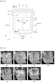
- FIG. 4 is a diagram illustrating an experimental example comparing the stirring effect according to the position of the foam breaker.
- the location where foam breaker FB was installed was changed, and accordingly the amount of foam generated and reduced was compared.
- H fb the depth from the surface LS of the emulsion in the container 100 to the center of the foam breaker FB
- H liquid the depth from the surface LS to the bottom surface of the container
- the solution is to accommodate 4L of ultrapure water containing 0.25% by weight of PVA in a container 100 with a volume of 10L, and the foam breaker FB is placed on top of the impeller IM and configured to rotate by the rotation shaft AX.
- the rotational speed of the rotation shaft AX was 250RMP, and after application for 15 minutes, the state of bubbles on the surface was observed.
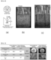
- FIG. 5 is a diagram illustrating micrographs of residual solvent, encapsulation rate, particle size and shape depending on whether compressed air is applied in the solvent removal apparatus according to an embodiment of the present invention.
- the aqueous phase includes PVA 0.25% by weight and ultrapure water
- a second raw material, the oil phase includes PLGA7504 Polymer (11.8% by weight), Finasteride (5.9% by weight), and DCM (82.3% by weight), depending on whether or not compressed air was applied, micrographs of residual solvent, encapsulation rate, particle size (size of the microspheres produced) and shape were confirmed.
- the diffusion layer (Diffusive Boundary Layer ⁇ _a) becomes thin, so that the solvent is smoothly evaporated.
- FIG. 6 is a diagram illustrating micrographs of residual solvent, encapsulation rate, particle size and shape according to whether or not the electric pump is applied in the solvent removal apparatus according to an embodiment of the present invention.
- FIG. 7 is a diagram illustrating micrographs of residual solvent, encapsulation rate, particle size and shape according to the position of the foam breaker in the solvent removal apparatus according to an embodiment of the present invention.
- a propeller blade-shaped structure with a diameter of 7cm was used as the foam breaker FB used in the experiment, and a propeller blade-shaped structure with a diameter of 11cm was used as the impeller IM.
- a depth H fb from the surface of the solution is D fb /2 based on a diameter D fb of the foam breaker, and when the foam breaker is applied to a depth of the solution, the experiment was conducted by applying H fb to 1.5 D fb .
- FIG. 8 is a diagram for comparing flowability according to whether or not baffle is applied in the solvent removal apparatus according to an embodiment of the present invention.
- FIG. 8(a) is a diagram illustrating the concept of a Vortex formed in a solution and Solid body rotation when only an impeller in a container is applied.
- FIG. 8(b) when the baffle BF is not applied, it is confirmed that the flow of the solution is not active in the vertical direction due to the formed vortex and solid body rotation when the rotational flow of the solution is generated.
- FIG. 8(c) confirms that when the baffle BF is applied, the formation of vortex is reduced at the same rotational speed, and the flow of the solution is active in the vertical direction.
- solvents in a dispersed phase of the solution are extracted into a continuous phase, resulting in a local high concentration of the solvent, which may reduce the extraction of the solvent and at a same time may affect the solidified microspheres or may occur precipitation of the drug in the microspheres.
- the generation of the Vortex may have an advantage of increasing the evaporation of the solvent by generating an effect of increasing the area of the Liquid-Air Interface.
- the Vortex due to the Vortex, the time the solution stays on the surface near the interface becomes longer, and the vertical flow of the solution deteriorates, resulting in inhibition of solvent evaporation.
- the Diffusion Coefficient of the solvent inside the solution is 1.2 ⁇ 10 ⁇ (-5) cm ⁇ 2/s, which is about 10,000 times lower than Diffusion (In Air Diffusion Coefficient 0.101 cm ⁇ 2/s), so that it may be seen that the inhibition of circulation in the solution is more disadvantageous for solvent evaporation than the effect of increasing the interface.
- these problems may have a greater impact.
- FIG. 9 is a repeated test result for an experimental example of the solvent removal apparatus according to an embodiment of the present invention.
- H fb a depth from the surface of the emulsion to a center of the foam breaker
- H liquid a depth from the surface to a bottom of the container
- H baffle a height from the bottom of the baffle to the surface of the emulsion
- H liquid a height from the bottom of the container to the surface of the emulsion
- FIG. 10 is a flowchart illustrating a method for manufacturing microspheres according to an embodiment of the present invention.
- method of manufacturing microsphere may include first and second raw material preparation step S100, emulsion formation step S200, solvent extraction removal step S300 and post-treatment step S400.
- a first raw material may be prepared, and a second raw material including a biodegradable polymer, a drug, and a solvent may be prepared.
- the first material may include Purified Water and a surfactant.
- the second raw material is an oil-phase solution, and may include an organic solvent, a biodegradable polymer dissolved therein, and a drug.
- an emulsion including the first raw material of the continuous phase and the second raw material of the dispersed phase may be formed using the first raw material and the second raw material.
- a method of mixing and stirring the first raw material and the second raw material, a microfluidic method of forming microsphere droplets through the flow of a microchannel, and the like may be used.
- the emulsion includes the first raw material in the continuous phase and the second raw material in the dispersed phase.
- the solvent of the dispersed phase of the emulsion may be removed by extraction and evaporation.
- the impeller is located above, and spaced apart from a container for accommodating the emulsion including the first raw material of the continuous phase and the second raw material of the dispersed phase, an impeller rotating in the container to stir the emulsion, and the impeller, when the emulsion is stirred by rotation, using a solvent removing apparatus including a foam breaker to reduce generated foam, it is possible to accelerate the extraction of the solvent from the dispersed phase of the emulsion to the continuous phase and evaporation of the extracted solvent. Through this, it is possible to form solidified microspheres.
- the solidified microspheres are washed and dried to finally prepare the desired monodisperse biodegradable polymer-based microsphere powder, thereafter, the obtained microsphere powder may be suspended in a suspension and filled in an appropriate container, such as a disposable syringe, to perform a post-treatment process to obtain a final product.
- an appropriate container such as a disposable syringe
Landscapes
- Chemical & Material Sciences (AREA)
- Organic Chemistry (AREA)
- Health & Medical Sciences (AREA)
- Dispersion Chemistry (AREA)
- Chemical Kinetics & Catalysis (AREA)
- Medicinal Chemistry (AREA)
- Epidemiology (AREA)
- Life Sciences & Earth Sciences (AREA)
- Animal Behavior & Ethology (AREA)
- General Health & Medical Sciences (AREA)
- Public Health (AREA)
- Veterinary Medicine (AREA)
- Pharmacology & Pharmacy (AREA)
- Engineering & Computer Science (AREA)
- Bioinformatics & Cheminformatics (AREA)
- Mixers Of The Rotary Stirring Type (AREA)
- Colloid Chemistry (AREA)
Claims (15)
- Lösungsmittelentfernungsvorrichtung, umfassend:einen Behälter (100), enthaltend eine Emulsion, die ein erstes Ausgangsmaterial einer kontinuierlichen Phase und ein zweites Ausgangsmaterial einer dispergierten Phase umfasst;ein Flügelrad (IM), das so konfiguriert ist, dass es sich in dem Behälter (100) dreht, um die Emulsion zu rühren;einen Schaumbrecher (FB), beabstandet von dem Flügelrad (IM) auf einem oberen Teil des Flügelrades (IM), positioniert unter einer Oberfläche (LS) der Emulsion, um in die Emulsion eingetaucht zu werden, wenn die Emulsion ruhig ist, und so konfiguriert, dass er sich dreht, um den während des Rührens der Emulsion erzeugten Schaum zu verringern; undeine Druckluftzufuhreinheit (114) zum Zuführen von Druckluft zu der Oberfläche (LS) der Emulsion in dem Behälter (100).
- Lösungsmittelentfernungsvorrichtung nach Anspruch 1, ferner umfassend:eine Rotationswelle (AX), verbunden mit dem Flügelrad (IM), um dem Flügelrad (IM) Rotationskraft zu verleihen,wobei der Schaumbrecher (FB) mit der Rotationswelle (AX) verbunden ist, und das Flügelrad (IM) und der Schaumbrecher (FB) so konfiguriert sind, dass sie sich durch die Rotation der Rotationswelle (AX) gleichzeitig drehen.
- Lösungsmittelentfernungsvorrichtung nach Anspruch 1, wenn eine Tiefe von der Oberfläche (LS) der Emulsion zu einer Mitte des Schaumbrechers (FB) als Hfb definiert ist, und eine Tiefe von der Oberfläche (LS) zu einer Bodenfläche des Behälters (100) als Hliquid definiert ist,
wobei Hfb/Hliquid 0,2 bis 0,5 entspricht. - Lösungsmittelentfernungsvorrichtung nach Anspruch 1, wenn ein Durchmesser des Flügelrades (IM) als Dmain definiert ist und ein Durchmesser des Schaumbrechers (FB) als Dfb definiert ist,
wobei Dfb/Dmain 0,3 bis 1 entspricht. - Lösungsmittelentfernungsvorrichtung nach Anspruch 1, wenn eine Innenseite des Behälters eine zylindrische Form aufweist, ein Durchmesser des Behälters als Dtank definiert ist, und ein Durchmesser des Schaumbrechers als Dfb definiert ist,
wobei Dfb/Dtank 0,3 bis 0,6 entspricht. - Lösungsmittelentfernungsvorrichtung nach Anspruch 1, ferner umfassend:
eine Luftableitungseinheit (112) zum Ableiten von Luft in dem Behälter (100) zu einer Außenseite des Behälters (100). - Lösungsmittelentfernungsvorrichtung nach Anspruch 1, wenn eine Tiefe von der Oberfläche der Emulsion zu einer Mitte des Schaumbrechers (FB) als Hfb definiert ist und ein Durchmesser des Schaumbrechers (FB) als Dfb definiert ist,
wobei der Wert von Hfb/Dfb zwischen 0,5 und 2 liegt. - Lösungsmittelentfernungsvorrichtung nach Anspruch 1, wobei der Behälter (100) wenigstens eine an einer Innenwand des Behälters (100) ausgebildete Prallplatte (BF), die in Richtung einer Mitte des Behälters (100) herausragt, umfasst.
- Lösungsmittelentfernungsvorrichtung nach Anspruch 8, wenn eine Höhe von einem untersten Teil der Prallplatte (BF) zu der Oberfläche der Emulsion als Hbaffle definiert ist und eine Höhe vom Boden des Behälters (100) zu der Oberfläche der Emulsion als Hliquid definiert ist,
wobei Hbaffle/Hliquid 0,6 bis 0,8 entspricht. - Lösungsmittelentfernungsvorrichtung nach Anspruch 8, wenn eine Innenseite des Behälters (100) eine zylindrische Form aufweist, eine Höhe der aus der Innenwand des Behälters (100) herausragenden Prallplatte (BF) als Wbaffle definiert ist, und ein Durchmesser des Behälters (100) als Dtank definiert ist,
wobei Wbaffle/Dtank 0,06 bis 0,10 entspricht. - Lösungsmittelentfernungsvorrichtung nach Anspruch 1, ferner umfassend:
eine Luftableitungspumpe zum Ableiten von Luft in dem Raum zu einer Außenseite des Behälters (100). - Verfahren zur Herstellung von Mikrokugeln, umfassend:Herstellen eines ersten Ausgangsmaterials und Herstellen eines zweiten Ausgangsmaterials, umfassend ein biologisch abbaubares Polymer, einen Arzneistoff und ein Lösungsmittel (S100);Bilden einer Emulsion, die das erste Ausgangsmaterial in einer kontinuierlichen Phase und das zweite Ausgangsmaterial in einer dispergierten Phase umfasst, unter Verwendung des ersten Ausgangsmaterials und des zweiten Ausgangsmaterials (S200);Liefern der Emulsion zu einer Lösungsmittelentfernungsvorrichtung; undeinen Schritt der Lösungsmittelextraktion/-entfernung (S300) des Extrahierens und Entfernens des Lösungsmittels der dispergierten Phase der Emulsion durch Rotieren eines Flügelrades (IM) und eines Schaumbrechers (FB) der Lösungsmittelentfernungsvorrichtung; undLiefern von Druckluft zu einer Oberfläche (LS) der Emulsion über eine Druckluftzufuhreinheit (114);wobei die Lösungsmittelentfernungsvorrichtung umfasst:einen Behälter (100) zum Aufnehmen der Emulsion;das Flügelrad (IM), das sich in dem Behälter (100) dreht, um die Emulsion zu rühren; undden Schaumbrecher (FB), beabstandet von dem oberen Teil des Flügelrades (IM), positioniert unter der Oberfläche (LS) der Emulsion, um in die Emulsion eingetaucht zu werden, wenn die Emulsion ruhig ist, und sich drehend, um den während des Rührens der Emulsion erzeugten Schaum zu verringern; unddie Druckluftzufuhreinheit (114 zum Zuführen von Druckluft zu der Oberfläche (LS) der Emulsion in dem Behälter (100).
- Verfahren zur Herstellung von Mikrokugeln nach Anspruch 12, in dem Schritt der Lösungsmittelextraktion/-entfernung (S300), wenn eine Tiefe von der Oberfläche (LS) der Emulsion zu einer Mitte des Schaumbrechers (FB) als Hfb definiert ist, und eine Tiefe von der Oberfläche zu einer Bodenfläche des Behälters (100) als Hliquid definiert ist,
wobei Hfb/Hliquid 0,5 bis 0,2 entspricht. - Verfahren zur Herstellung von Mikrokugeln nach Anspruch 12, in dem Schritt der Lösungsmittelextraktion/-entfernung (S300), wenn eine Tiefe von der Oberfläche (LS) der Emulsion zu einer Mitte des Schaumbrechers (FB) als Hfb definiert ist, und ein Durchmesser des Schaumbrechers als Dfb definiert ist,
wobei der Wert von Hfb/Dfb zwischen 0,5 bis 2 liegt. - Verfahren zur Herstellung von Mikrokugeln nach Anspruch 12, in dem Schritt der Lösungsmittelextraktion/-entfernung (S300),
wobei der Behälter (100) wenigstens eine an einer Innenwand des Behälters (100) ausgebildete Prallplatte (BF), die in Richtung einer Mitte des Behälters (100) herausragt, umfasst.
Priority Applications (1)
| Application Number | Priority Date | Filing Date | Title |
|---|---|---|---|
| EP24222777.5A EP4545174A1 (de) | 2021-12-22 | 2022-12-14 | Lösungsmittelentfernungsvorrichtung und verfahren zur herstellung von mikrokugeln damit |
Applications Claiming Priority (1)
| Application Number | Priority Date | Filing Date | Title |
|---|---|---|---|
| KR20210184474 | 2021-12-22 |
Related Child Applications (2)
| Application Number | Title | Priority Date | Filing Date |
|---|---|---|---|
| EP24222777.5A Division-Into EP4545174A1 (de) | 2021-12-22 | 2022-12-14 | Lösungsmittelentfernungsvorrichtung und verfahren zur herstellung von mikrokugeln damit |
| EP24222777.5A Division EP4545174A1 (de) | 2021-12-22 | 2022-12-14 | Lösungsmittelentfernungsvorrichtung und verfahren zur herstellung von mikrokugeln damit |
Publications (2)
| Publication Number | Publication Date |
|---|---|
| EP4201511A1 EP4201511A1 (de) | 2023-06-28 |
| EP4201511B1 true EP4201511B1 (de) | 2025-02-12 |
Family
ID=84535794
Family Applications (2)
| Application Number | Title | Priority Date | Filing Date |
|---|---|---|---|
| EP22213457.9A Active EP4201511B1 (de) | 2021-12-22 | 2022-12-14 | Lösungsmittelentfernungsvorrichtung und verfahren zur herstellung von mikrokugeln damit |
| EP24222777.5A Pending EP4545174A1 (de) | 2021-12-22 | 2022-12-14 | Lösungsmittelentfernungsvorrichtung und verfahren zur herstellung von mikrokugeln damit |
Family Applications After (1)
| Application Number | Title | Priority Date | Filing Date |
|---|---|---|---|
| EP24222777.5A Pending EP4545174A1 (de) | 2021-12-22 | 2022-12-14 | Lösungsmittelentfernungsvorrichtung und verfahren zur herstellung von mikrokugeln damit |
Country Status (1)
| Country | Link |
|---|---|
| EP (2) | EP4201511B1 (de) |
Family Cites Families (5)
| Publication number | Priority date | Publication date | Assignee | Title |
|---|---|---|---|---|
| AU2003262048A1 (en) * | 2002-09-11 | 2004-04-30 | Tanabe Seiyaku Co., Ltd. | Process for the production of microspheres and unit therefor |
| KR20050109384A (ko) * | 2004-05-15 | 2005-11-21 | 임교빈 | 초임계 유체를 이용한 5-플루오로우라실의 서방성 방출을위한 고분자 미립자 제조장치 및 제조방법 |
| WO2014094793A1 (en) * | 2012-12-19 | 2014-06-26 | Flsmidth A/S | Apparatus and method for solvent extraction processing |
| US9439864B2 (en) * | 2014-07-07 | 2016-09-13 | Antriabio, Inc. | Solvent extraction from biodegradable microparticles |
| KR102283250B1 (ko) * | 2020-12-24 | 2021-07-29 | (주)인벤티지랩 | 용매 제거 장치 및 이를 이용한 미소구체 제조 방법 |
-
2022
- 2022-12-14 EP EP22213457.9A patent/EP4201511B1/de active Active
- 2022-12-14 EP EP24222777.5A patent/EP4545174A1/de active Pending
Also Published As
| Publication number | Publication date |
|---|---|
| EP4201511A1 (de) | 2023-06-28 |
| EP4545174A1 (de) | 2025-04-30 |
Similar Documents
| Publication | Publication Date | Title |
|---|---|---|
| US11944949B2 (en) | Solvent removing apparatus and method of manufacturing microsphere using the same | |
| CN110709067B (zh) | 用于制备具有改善的稳定性和贮存稳定性的生物可降解微球的方法 | |
| EP4268917B1 (de) | Vorrichtung zur entfernung von lösungsmitteln und verfahren zur herstellung von mikrokügelchen damit | |
| US12521348B2 (en) | Microsphere producing system and microsphere producing method | |
| JPH11505250A (ja) | 製造規模の微粒子生成方法 | |
| EP4201511A1 (de) | Lösungsmittelentfernungsvorrichtung und verfahren zur herstellung von mikrokugeln damit | |
| CN109700780A (zh) | 一种高包封率的亲水性药物缓释微球及其制备方法 | |
| EP4483980A1 (de) | Lösungsmittelentfernungsvorrichtung und verfahren zur herstellung von mikrokugeln damit | |
| KR102431191B1 (ko) | 미소구체 제조 장치 및 미소구체 제조 방법 | |
| HK1008937B (en) | Production scale method of forming microparticles |
Legal Events
| Date | Code | Title | Description |
|---|---|---|---|
| PUAI | Public reference made under article 153(3) epc to a published international application that has entered the european phase |
Free format text: ORIGINAL CODE: 0009012 |
|
| STAA | Information on the status of an ep patent application or granted ep patent |
Free format text: STATUS: THE APPLICATION HAS BEEN PUBLISHED |
|
| AK | Designated contracting states |
Kind code of ref document: A1 Designated state(s): AL AT BE BG CH CY CZ DE DK EE ES FI FR GB GR HR HU IE IS IT LI LT LU LV MC ME MK MT NL NO PL PT RO RS SE SI SK SM TR |
|
| STAA | Information on the status of an ep patent application or granted ep patent |
Free format text: STATUS: REQUEST FOR EXAMINATION WAS MADE |
|
| 17P | Request for examination filed |
Effective date: 20231218 |
|
| RBV | Designated contracting states (corrected) |
Designated state(s): AL AT BE BG CH CY CZ DE DK EE ES FI FR GB GR HR HU IE IS IT LI LT LU LV MC ME MK MT NL NO PL PT RO RS SE SI SK SM TR |
|
| STAA | Information on the status of an ep patent application or granted ep patent |
Free format text: STATUS: EXAMINATION IS IN PROGRESS |
|
| 17Q | First examination report despatched |
Effective date: 20240315 |
|
| GRAP | Despatch of communication of intention to grant a patent |
Free format text: ORIGINAL CODE: EPIDOSNIGR1 |
|
| STAA | Information on the status of an ep patent application or granted ep patent |
Free format text: STATUS: GRANT OF PATENT IS INTENDED |
|
| INTG | Intention to grant announced |
Effective date: 20240904 |
|
| GRAS | Grant fee paid |
Free format text: ORIGINAL CODE: EPIDOSNIGR3 |
|
| GRAA | (expected) grant |
Free format text: ORIGINAL CODE: 0009210 |
|
| STAA | Information on the status of an ep patent application or granted ep patent |
Free format text: STATUS: THE PATENT HAS BEEN GRANTED |
|
| AK | Designated contracting states |
Kind code of ref document: B1 Designated state(s): AL AT BE BG CH CY CZ DE DK EE ES FI FR GB GR HR HU IE IS IT LI LT LU LV MC ME MK MT NL NO PL PT RO RS SE SI SK SM TR |
|
| REG | Reference to a national code |
Ref country code: GB Ref legal event code: FG4D |
|
| REG | Reference to a national code |
Ref country code: CH Ref legal event code: EP |
|
| REG | Reference to a national code |
Ref country code: DE Ref legal event code: R096 Ref document number: 602022010466 Country of ref document: DE |
|
| REG | Reference to a national code |
Ref country code: IE Ref legal event code: FG4D |
|
| REG | Reference to a national code |
Ref country code: NL Ref legal event code: MP Effective date: 20250212 |
|
| PG25 | Lapsed in a contracting state [announced via postgrant information from national office to epo] |
Ref country code: RS Free format text: LAPSE BECAUSE OF FAILURE TO SUBMIT A TRANSLATION OF THE DESCRIPTION OR TO PAY THE FEE WITHIN THE PRESCRIBED TIME-LIMIT Effective date: 20250512 |
|
| PG25 | Lapsed in a contracting state [announced via postgrant information from national office to epo] |
Ref country code: FI Free format text: LAPSE BECAUSE OF FAILURE TO SUBMIT A TRANSLATION OF THE DESCRIPTION OR TO PAY THE FEE WITHIN THE PRESCRIBED TIME-LIMIT Effective date: 20250212 |
|
| PG25 | Lapsed in a contracting state [announced via postgrant information from national office to epo] |
Ref country code: PL Free format text: LAPSE BECAUSE OF FAILURE TO SUBMIT A TRANSLATION OF THE DESCRIPTION OR TO PAY THE FEE WITHIN THE PRESCRIBED TIME-LIMIT Effective date: 20250212 |
|
| PG25 | Lapsed in a contracting state [announced via postgrant information from national office to epo] |
Ref country code: ES Free format text: LAPSE BECAUSE OF FAILURE TO SUBMIT A TRANSLATION OF THE DESCRIPTION OR TO PAY THE FEE WITHIN THE PRESCRIBED TIME-LIMIT Effective date: 20250212 |
|
| REG | Reference to a national code |
Ref country code: LT Ref legal event code: MG9D |
|
| PG25 | Lapsed in a contracting state [announced via postgrant information from national office to epo] |
Ref country code: NO Free format text: LAPSE BECAUSE OF FAILURE TO SUBMIT A TRANSLATION OF THE DESCRIPTION OR TO PAY THE FEE WITHIN THE PRESCRIBED TIME-LIMIT Effective date: 20250512 Ref country code: IS Free format text: LAPSE BECAUSE OF FAILURE TO SUBMIT A TRANSLATION OF THE DESCRIPTION OR TO PAY THE FEE WITHIN THE PRESCRIBED TIME-LIMIT Effective date: 20250612 |
|
| PG25 | Lapsed in a contracting state [announced via postgrant information from national office to epo] |
Ref country code: NL Free format text: LAPSE BECAUSE OF FAILURE TO SUBMIT A TRANSLATION OF THE DESCRIPTION OR TO PAY THE FEE WITHIN THE PRESCRIBED TIME-LIMIT Effective date: 20250212 |
|
| PG25 | Lapsed in a contracting state [announced via postgrant information from national office to epo] |
Ref country code: HR Free format text: LAPSE BECAUSE OF FAILURE TO SUBMIT A TRANSLATION OF THE DESCRIPTION OR TO PAY THE FEE WITHIN THE PRESCRIBED TIME-LIMIT Effective date: 20250212 |
|
| PG25 | Lapsed in a contracting state [announced via postgrant information from national office to epo] |
Ref country code: PT Free format text: LAPSE BECAUSE OF FAILURE TO SUBMIT A TRANSLATION OF THE DESCRIPTION OR TO PAY THE FEE WITHIN THE PRESCRIBED TIME-LIMIT Effective date: 20250612 Ref country code: LV Free format text: LAPSE BECAUSE OF FAILURE TO SUBMIT A TRANSLATION OF THE DESCRIPTION OR TO PAY THE FEE WITHIN THE PRESCRIBED TIME-LIMIT Effective date: 20250212 |
|
| PG25 | Lapsed in a contracting state [announced via postgrant information from national office to epo] |
Ref country code: BG Free format text: LAPSE BECAUSE OF FAILURE TO SUBMIT A TRANSLATION OF THE DESCRIPTION OR TO PAY THE FEE WITHIN THE PRESCRIBED TIME-LIMIT Effective date: 20250212 Ref country code: GR Free format text: LAPSE BECAUSE OF FAILURE TO SUBMIT A TRANSLATION OF THE DESCRIPTION OR TO PAY THE FEE WITHIN THE PRESCRIBED TIME-LIMIT Effective date: 20250513 |
|
| REG | Reference to a national code |
Ref country code: AT Ref legal event code: MK05 Ref document number: 1765576 Country of ref document: AT Kind code of ref document: T Effective date: 20250212 |
|
| PG25 | Lapsed in a contracting state [announced via postgrant information from national office to epo] |
Ref country code: SE Free format text: LAPSE BECAUSE OF FAILURE TO SUBMIT A TRANSLATION OF THE DESCRIPTION OR TO PAY THE FEE WITHIN THE PRESCRIBED TIME-LIMIT Effective date: 20250212 |
|
| PG25 | Lapsed in a contracting state [announced via postgrant information from national office to epo] |
Ref country code: SM Free format text: LAPSE BECAUSE OF FAILURE TO SUBMIT A TRANSLATION OF THE DESCRIPTION OR TO PAY THE FEE WITHIN THE PRESCRIBED TIME-LIMIT Effective date: 20250212 |
|
| PG25 | Lapsed in a contracting state [announced via postgrant information from national office to epo] |
Ref country code: DK Free format text: LAPSE BECAUSE OF FAILURE TO SUBMIT A TRANSLATION OF THE DESCRIPTION OR TO PAY THE FEE WITHIN THE PRESCRIBED TIME-LIMIT Effective date: 20250212 |
|
| PG25 | Lapsed in a contracting state [announced via postgrant information from national office to epo] |
Ref country code: IT Free format text: LAPSE BECAUSE OF FAILURE TO SUBMIT A TRANSLATION OF THE DESCRIPTION OR TO PAY THE FEE WITHIN THE PRESCRIBED TIME-LIMIT Effective date: 20250212 |
|
| PG25 | Lapsed in a contracting state [announced via postgrant information from national office to epo] |
Ref country code: AT Free format text: LAPSE BECAUSE OF FAILURE TO SUBMIT A TRANSLATION OF THE DESCRIPTION OR TO PAY THE FEE WITHIN THE PRESCRIBED TIME-LIMIT Effective date: 20250212 |
|
| PG25 | Lapsed in a contracting state [announced via postgrant information from national office to epo] |
Ref country code: CZ Free format text: LAPSE BECAUSE OF FAILURE TO SUBMIT A TRANSLATION OF THE DESCRIPTION OR TO PAY THE FEE WITHIN THE PRESCRIBED TIME-LIMIT Effective date: 20250212 Ref country code: EE Free format text: LAPSE BECAUSE OF FAILURE TO SUBMIT A TRANSLATION OF THE DESCRIPTION OR TO PAY THE FEE WITHIN THE PRESCRIBED TIME-LIMIT Effective date: 20250212 |
|
| PG25 | Lapsed in a contracting state [announced via postgrant information from national office to epo] |
Ref country code: RO Free format text: LAPSE BECAUSE OF FAILURE TO SUBMIT A TRANSLATION OF THE DESCRIPTION OR TO PAY THE FEE WITHIN THE PRESCRIBED TIME-LIMIT Effective date: 20250212 |
|
| PG25 | Lapsed in a contracting state [announced via postgrant information from national office to epo] |
Ref country code: SK Free format text: LAPSE BECAUSE OF FAILURE TO SUBMIT A TRANSLATION OF THE DESCRIPTION OR TO PAY THE FEE WITHIN THE PRESCRIBED TIME-LIMIT Effective date: 20250212 |
|
| REG | Reference to a national code |
Ref country code: DE Ref legal event code: R097 Ref document number: 602022010466 Country of ref document: DE |
|
| PLBE | No opposition filed within time limit |
Free format text: ORIGINAL CODE: 0009261 |
|
| STAA | Information on the status of an ep patent application or granted ep patent |
Free format text: STATUS: NO OPPOSITION FILED WITHIN TIME LIMIT |
|
| PGFP | Annual fee paid to national office [announced via postgrant information from national office to epo] |
Ref country code: FR Payment date: 20251218 Year of fee payment: 4 |
|
| 26N | No opposition filed |
Effective date: 20251113 |
|
| PGFP | Annual fee paid to national office [announced via postgrant information from national office to epo] |
Ref country code: DE Payment date: 20251218 Year of fee payment: 4 |