EP4201267B1 - Montagehalterung für vorhangstange - Google Patents
Montagehalterung für vorhangstange Download PDFInfo
- Publication number
- EP4201267B1 EP4201267B1 EP21809898.6A EP21809898A EP4201267B1 EP 4201267 B1 EP4201267 B1 EP 4201267B1 EP 21809898 A EP21809898 A EP 21809898A EP 4201267 B1 EP4201267 B1 EP 4201267B1
- Authority
- EP
- European Patent Office
- Prior art keywords
- fixing portion
- groove
- sliding
- block
- curtain rod
- Prior art date
- Legal status (The legal status is an assumption and is not a legal conclusion. Google has not performed a legal analysis and makes no representation as to the accuracy of the status listed.)
- Active
Links
Images


Classifications
-
- A—HUMAN NECESSITIES
- A47—FURNITURE; DOMESTIC ARTICLES OR APPLIANCES; COFFEE MILLS; SPICE MILLS; SUCTION CLEANERS IN GENERAL
- A47H—FURNISHINGS FOR WINDOWS OR DOORS
- A47H1/00—Curtain suspension devices
- A47H1/10—Means for mounting curtain rods or rails
- A47H1/14—Brackets for supporting rods or rails
- A47H1/142—Brackets for supporting rods or rails for supporting rods
-
- A—HUMAN NECESSITIES
- A47—FURNITURE; DOMESTIC ARTICLES OR APPLIANCES; COFFEE MILLS; SPICE MILLS; SUCTION CLEANERS IN GENERAL
- A47H—FURNISHINGS FOR WINDOWS OR DOORS
- A47H1/00—Curtain suspension devices
- A47H1/10—Means for mounting curtain rods or rails
- A47H1/12—Adjustable mountings
-
- A—HUMAN NECESSITIES
- A47—FURNITURE; DOMESTIC ARTICLES OR APPLIANCES; COFFEE MILLS; SPICE MILLS; SUCTION CLEANERS IN GENERAL
- A47H—FURNISHINGS FOR WINDOWS OR DOORS
- A47H1/00—Curtain suspension devices
- A47H1/10—Means for mounting curtain rods or rails
- A47H1/12—Adjustable mountings
- A47H1/122—Adjustable mountings for curtain rods
-
- A—HUMAN NECESSITIES
- A47—FURNITURE; DOMESTIC ARTICLES OR APPLIANCES; COFFEE MILLS; SPICE MILLS; SUCTION CLEANERS IN GENERAL
- A47H—FURNISHINGS FOR WINDOWS OR DOORS
- A47H1/00—Curtain suspension devices
- A47H1/10—Means for mounting curtain rods or rails
- A47H1/14—Brackets for supporting rods or rails
Definitions
- the present application relates to the field of curtain accessories, and in particular, to a curtain rod mounting bracket.
- the curtain system also includes a curtain rod and a mounting bracket for holding the curtain rod.
- the mounting bracket is generally fixed on the wall according to the hanging position of curtains, and then the curtain cloth is hung on the curtain rod, and curtain rod is mounted to the mounting bracket afterwards, so as to hang the curtains with the support of the mounting bracket.
- the curtain cloth is pulled repeatedly when in use, which further drags the curtain rod. Therefore, in order to prevent the curtain rod from falling when in use, the mounting bracket generally needs to be matched with the type of the curtain rod, so that the curtain rod is better fixed. Consequently, there is a one-to-one matching relationship between mounting brackets and curtain rods for most of the curtains at present.
- the mounting bracket and curtain rod are not matched during delivery. Due to the low universality between different types of mounting brackets, the curtain rod may not be mounted to the mounting bracket, or it may be difficult to be fixed after installation.
- the patent application CN211324263U discloses an easy-to-install telescopic bracket, and its structural feature is that it includes a base, a support rod and a U-shaped support part; a fixed connection between the base and the support rod; the U-shaped supporting portion includes a connecting rod, the connecting rod is connected with the supporting rod and can be adjusted in length.
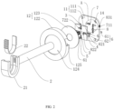
- a curtain rod mounting bracket includes a base and a supporting rod mounted to the base, a rod holding support is provided on the end of the supporting rod away from the base, a mounting groove is formed in the rod holding support, a curtain rod positioning clamp is detachably mounted in the mounting groove, a curtain rod loading opening is formed in the curtain rod positioning clamp, and the opening size of the curtain rod loading opening is smaller than the internal size of the curtain rod loading opening;
- the base includes a connecting base used for connecting with the supporting rod and a protecting cover sleeved on the supporting rod and covering the connecting base, the connecting base is provided with a stud used for connecting with the supporting rod and connecting holes distributing around the stud, and a screw hole used for forming screw connection with the stud is provided on the end of the supporting rod away from the rod holding support;
- the connecting base includes a fixing portion and a sliding portion in a slidable connection with the fixing portion, the stud is positioned in the sliding portion, a connector used
- each mounting bracket can be equipped with a plurality of curtain rod positioning clamps with different sizes of the curtain rod loading opening.
- the curtain rod positioning clamp is detachable, when the diameter of the curtain rod does not match the type of the mounting bracket, the curtain rod positioning clamp with different sizes of the curtain rod loading opening can be replaced, so that the mounting bracket can be adapted to the installation of the curtain rod to improve the universality of the mounting bracket.
- the curtain rod positioning clamp includes at least two clamping legs, the curtain rod loading opening is formed between two clamping legs, a positioning fin is provided on the sidewall of the clamping leg, a fin groove is provided on the inner wall of the mounting groove for inserting the positioning fin.
- the positioning fin can match with the fin groove in the rod holding support to limiting the separation of the curtain rod positioning clamp from the mounting groove.
- the positioning fin can be deformed in the installation process of the curtain rod, so as to enlarge the curtain rod loading opening, which facilitates the enter of the curtain rod into the interior of the curtain rod positioning clamp.
- the positioning fin is reset, which leads to the contraction of the curtain rod loading opening, so as to form a restriction to the curtain rod to realize the fixed connection of the curtain rod to the supporting rod.
- the positioning fin is inclinedly arranged, and the inclined direction of the positioning fin is consistent with the opening orientation of the curtain rod loading opening.
- the inclined arrangement of the positioning fin when the curtain rod is in contact with the curtain rod positioning clamp, a force can be better applied to the positioning fin, so that the positioning fin is prone to be extruded and bended to facilitate pressing the curtain rod into the curtain rod loading opening.
- the inclined direction of the positioning fin is consistent with the opening orientation of the curtain rod loading opening, so that when the positioning fin detaches from the mounting groove, the positioning fin can form a better hooking relation with the inner wall of the fin groove to better prevent the separation of the positioning fin from the mounting groove.
- the fixing portion and the sliding portion are both provided with an X-direction sliding groove and a Y-direction sliding groove
- the X-direction sliding groove in the fixing portion corresponds with the Y-direction sliding groove in the sliding portion
- the Y-direction sliding groove in the fixing portion corresponds with the X-direction sliding groove in the sliding portion
- a fastening protrusion is formed on the inner wall of the X-direction sliding grooves and the Y-direction sliding grooves in the fixing portion and the sliding portion
- the connector includes a connecting piece and a connecting block
- an extension block is protruded and formed on both sides of the connecting blocks
- the extension block on the side of the connecting block penetrates the center of the fastening protrusion in the fixing portion
- the extension block on another side penetrates the center of the fastening protrusion in the sliding portion
- the connecting pieces are fixedly connected with the ends of two extension blocks penetrating the fastening protrusion respectively.
- the X-direction sliding groove in the fixing portion corresponds with the Y-direction sliding groove in the sliding portion
- the Y-direction sliding groove in the fixing portion corresponds with the X-direction sliding groove in the sliding portion
- the X-direction sliding groove in the fixing portion and the Y-direction sliding groove in the sliding portion are in a perpendicular and crossed state
- the Y-direction sliding groove in the fixing portion and the X-direction sliding groove in the sliding portion are in a perpendicular and crossed state
- the X-direction guiding block can squeeze the inner wall of the X-direction sliding groove in the sliding portion, so as to push the sliding portion to move in the X direction.
- the Y-direction adjusting assembly also includes an adjusting ring
- the fixing portion is provided with a placing groove used for placing the Y-direction adjusting screw
- the adjusting ring is sleeved on the end of the X-direction adjusting screw positioning outside the fixing portion
- the end of the adjusting ring penetrates through the sidewall of the fixing portion and into the placing groove
- an oblique meshing tooth is provided on the end of the adjusting ring into the placing groove
- a bevel gear is fixed on the end of the Y-direction adjusting screw closing to the adjusting ring
- the oblique meshing tooth is meshed with the bevel gear.
- the protecting cover includes a cover body and an adaptive gasket, the cover body is formed with a movable opening with a smaller diameter than the diameter of the adaptive gasket, and the supporting rod penetrates the center of the adaptive gasket and is positioned inside the movable opening.
- the adaptive gasket can be changed according to the position of the supporting rod relative to the fixing portion, and the relative position between the adaptive gasket and the cover body is adjusted.
- the adaptive gasket can cover the movable opening when changing the adaptive gasket position, so that the mounting bracket has a better aesthetics.
- a fin groove 212 is provided on the inner wall of the mounting groove 211.
- positioning fins 223 are integrally formed on the sides of two clamping legs 221 opposite to each other in the curtain rod positioning clamp 22 respectively.
- the positioning fins 223 is inclinedly arranged, and the inclined direction of the positioning fin 223 is consistent with the opening orientation of the curtain rod loading opening 222.
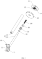
- the connecting base 11 includes two parts, a fixing portion 111 and a sliding portion 112., in which the size of the fixing portion 11 is larger than that of the sliding portion 112.
- the connecting hole 14 is positioned in the fixing portion 111
- the stud 13 is positioned in the sliding portion 112.
- the fixing portion 111 and the sliding portion 112 are both provided with an X-direction sliding groove 3 and a Y-direction sliding groove 4, in which the length direction of the Y-direction sliding groove 4 is perpendicular to that of the X-direction sliding groove 3.
- the fixing portion 111 and the sliding portion 112 are connected with each other by a connector 6.
- the connector 6 includes a connecting piece 61 and a connecting block 62.
- An extension block 621 is protruded and formed on both sides of the connecting blocks 62, the extension block 621 on one side of the connecting block 62 penetrates the center of the fastening protrusion 5 in the fixing portion 111 and the extension block 621 on another side of the connecting block 62 penetrates the center of the fastening protrusion 5 in the sliding portion 112.
- the X-direction adjusting screw 71 is rotatably mounted to the fixing portion 111, and penetrates the Y-direction guiding groove 9 in the form of parallel to the length direction of the Y-direction guiding groove 9, so that the middle of the X-direction adjusting screw is positioned in the Y-direction guiding groove.
- a Y-block extension portion 821 is protruded and formed in the Y-direction guiding block 82, the Y-block extension portion 821 penetrates the center of the fastening protrusion 5 in the Y-direction sliding groove 4 of the sliding portion 112, and a Y-block positioning piece 822 is fixed on the end of the Y-block extension portion 821 penetrating the center of the fastening protrusion 5, so as to connect the Y-direction guiding block 82 with the sliding portion 112.
- An oblique meshing tooth 832 is provided on the end of the adjusting ring 83 into the placing groove 40, a bevel gear 811 is fixed on the end of the Y-direction adjusting screw 81 closing to the adjusting ring 83, and the oblique meshing tooth 832 is meshed with the bevel gear 811, so that the Y-direction adjusting screw 81 can be driven to rotate by rotating the end of the adjusting ring 83 positioning outside the fixing portion 111.
- the axial direction of the X-direction adjusting screw 71 is the X direction in which the sliding portion 112 moves
- the axial direction of the Y-direction adjusting screw 81 is the Y direction in which the sliding part 112 moves.
- the rod holding support 21 is additionally provided with a buckle ring 60 in semicircle shape.
- One end of the buckle ring 60 is hinged with the rod holding support 21, and the hinging position is positioned on the end of the rod holding support 21 closing to support rod 2.
- Another end of the buckle ring 60 can rotate freely. After the free end of the buckle ring 60 is buckled on the rod holding support 21, it is combined with the rod holding support 21 to form a closed annular structure.
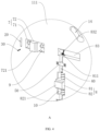
- the rod holding support 21 is fixed on the end of the telescopic portion 24, and another end of the telescopic portion 24 is inserted inside the supporting portion 23 through the smaller end of the supporting portion 23.
- a damping assembly is installed on the end of the telescopic portion 24 inside the supporting portion 23 for limiting the separation of the telescopic portion 24 from supporting portion 23.
- the damping assembly includes a damping ring 70 in an annular shape, the material of which can be elastic metal or plastic.
- a plurality of damping protrusions distributing around the damping ring 70 are integrally formed on the circumferential sidewall of the damping ring 70.
- the end of the telescopic portion 24 positioning inside the supporting portion 23 penetrates the center of the damping ring 70, and the telescopic portion 24 and the damping ring 70 are fixed through fastener 100, which can choose bolt or screw.
- a blocking piece 80 and an extrusion block 90 are sleeved on the telescopic portion 24 and positioned on both sides of the damping ring 70 respectively.
- the blocking piece 80 can block the contact between the damping ring 70 and the opening edge of the smaller end of the opening of the supporting portion 23, so as to protect the damping ring 70.
- the blocking piece 80 can squeeze the damping ring 70 during the screwing of the fastener 100, so that the damping ring 70 is swelled, and the friction between the damping ring 70 and the supporting portion 23 is adjusted.
Landscapes
- Curtains And Furnishings For Windows Or Doors (AREA)
Claims (6)
- Gardinenstangenhalterung, die eine Basis (1) und eine an der Basis (1) befestigte Haltestange (2) umfasst, wobei eine Stangenhalterung (21) an dem von der Basis (1) abgewandten Ende der Haltestange (2) vorgesehen ist, wobei eine Montagenut (211) in der Stangenhalterung (21) ausgebildet ist, wobei eine Gardinenstangen-Positionierungsklemme (22) abnehmbar in der Montagenut (211) montiert ist, worin eine Gardinenstangen-Ladeöffnung (222) in der Gardinenstangen-Positionierungsklemme (22) ausgebildet ist, wobei die Größe der Öffnung der Gardinenstangen-Ladeöffnung (222) kleiner ist als die Innengröße der Gardinenstangen-Ladeöffnung (222); hiervon umfasst die Basis (1) eine Verbindungsbasis (11), die zum Verbinden mit der Haltestange (2) verwendet wird, und eine Schutzabdeckung (12), die auf die Haltestange (2) aufgesetzt ist und die Verbindungsbasis (11) abdeckt, wobei die Verbindungsbasis (11) mit einem Bolzen (13), der zum Verbinden mit der Haltestange (2) verwendet wird, und mit Verbindungslöchern (14), die um den Bolzen (13) herum verteilt angeordnet sind, versehen ist, wobei ein Schraubenloch zum Herstellen einer Schraubverbindung mit dem Bolzen (13) an dem von der Stangenhalterung (21) entfernten Ende der Haltestange (2) vorgesehen ist, dadurch gekennzeichnet, dass die Verbindungsbasis (11) einen Befestigungsabschnitt (111) und einen Gleitabschnitt (112) in einer Gleitverbindung mit dem Befestigungsabschnitt (111) umfasst, wobei der Bolzen (13) in dem Gleitabschnitt (112) positioniert ist, wobei ein Verbinder (6), der zur Begrenzung der Trennung des Befestigungsabschnitts (111) und des Gleitabschnitts (112) verwendet wird, zwischen dem Befestigungsabschnitt (111) und dem Gleitabschnitt (112) vorgesehen ist, und wobei der Befestigungsabschnitt (111) mit einer X-Richtungs-Einstellbaugruppe (7) versehen ist, die zum Antreiben des Gleitabschnitts (112) in dem Befestigungsabschnitt (111) zum Bewegen entlang einer X-Richtung benutzt wird, und einer Y-Richtungs-Einstellbaugruppe (8), die zum Antreiben des Gleitabschnitts (112) verwendet wird, der in dem Befestigungsabschnitt (111) entlang einer Y-Richtung bewegt wird.
- Gardinenstangenhalterung nach Anspruch 1, dadurch gekennzeichnet, dass die Gardinenstangen-Positionierklemme (22) mindestens zwei Klemmschenkel (221) aufweist, dass die Gardinenstangen-Ladeöffnung (222) zwischen zwei Klemmschenkeln (221) ausgebildet ist, dass an der Seitenwand des Klemmschenkels (221) eine Positionierrippe (223) vorgesehen ist, dass an der Innenwand der Befestigungsnut (211) eine Rippennut (212) zum Einsetzen der Positionierrippe (223) vorgesehen ist.
- Gardinenstangenhalterung nach Anspruch 2, dadurch gekennzeichnet, dass die Positionierrippe (223) schräg angeordnet ist und die Schrägrichtung der Positionierrippe (223) mit der Öffnungsrichtung der Gardinenstangeneinführöffnung (222) übereinstimmt.
- Gardinenstangenhalterung nach Anspruch 1, dadurch gekennzeichnet, dass der Befestigungsabschnitt (111) und der Gleitabschnitt (112) beide mit einer in X-Richtung verlaufenden Gleitnut (3) und einer in Y-Richtung verlaufenden Gleitnut (4) versehen sind, wobei die in X-Richtung verlaufende Gleitnut (3) im Befestigungsabschnitt (111) mit der in Y-Richtung verlaufenden Gleitnut (4) im Gleitabschnitt (112) übereinstimmt, die Gleitnut (4) in Y-Richtung im Befestigungsabschnitt (111) mit der Gleitnut (3) in X-Richtung im Gleitabschnitt (112) korrespondiert, dass ein Befestigungsvorsprung (5) an der Innenwand der Gleitnut (3) in X-Richtung und der Gleitnut (4) in Y-Richtung im Befestigungsabschnitt (111) und im Gleitabschnitt (112) ausgebildet ist, dass der Verbinder (6) ein Verbindungsstück (61) und einen Verbindungsblock (62) umfasst, wobei ein Verlängerungsblock (621) auf beiden Seiten der Verbindungsblöcke (62) ausgebildet ist und davon absteht, dass der Verlängerungsblock (621) auf der Seite des Verbindungsblocks (62) in die Mitte des Befestigungsvorsprungs (5) in dem Befestigungsabschnitt (111) eindringt und der Verlängerungsblock (621) auf einer anderen Seite in die Mitte des Befestigungsvorsprungs (5) in dem Gleitabschnitt (112) eindringt, und wobei die Verbindungsstücke (61) fest mit den Enden von zwei Verlängerungsblöcken (621) verbunden sind, die jeweils in den Befestigungsvorsprung (5) eindringen.
- Gardinenstangenhalterung nach Anspruch 4, dadurch gekennzeichnet, dass die X-Richtungs-Einstellbaugruppe (7) eine X-Richtungs-Einstellschraube (71), die drehbar an dem Befestigungsabschnitt (111) angebracht ist, und einen X-Richtungs-Führungsblock (72) umfasst, dessen eines Ende mit dem Gleitabschnitt (112) verbunden ist und dessen anderes Ende auf die X-Richtungsschraube (71) aufgeschraubt ist, wobei der Befestigungsabschnitt (111) auch mit einer Y-Führungsnut (9) versehen ist, die parallel zu der Y-Gleitnut (4) des Befestigungsabschnitts (111) verläuft, wobei die X-Einstellschraube (71) in die Y-Führungsnut (9) eindringt und parallel zur Längsrichtung der Y-Führungsnut (9) verläuft, wobei das Ende des X-Führungsblocks (72), das mit der X-Einstellschraube (71) verbunden ist, in der Y-Führungsnut (9) positioniert ist, ein X-Block-Verlängerungsabschnitt (721) aus dem X-Führungsblock (72) herausragt und darin ausgebildet ist, dass der X-Block-Verlängerungsabschnitt (721) in die Mitte des Befestigungsvorsprungs (5) in der in X-Richtung Gleitnut (3) des Gleitabschnitts (112) eindringt, und ein X-Block-Positionierungsteil (722) an dem Ende des X-Block-Verlängerungsabschnitts (721) befestigt ist, der in die Mitte des Befestigungsvorsprungs (5) eindringt.
- Gardinenstangenhalterung nach Anspruch 5, dadurch gekennzeichnet, dass die Y-Richtungs-Einstellbaugruppe (8) eine Y-Richtungs-Einstellschraube (81), die drehbar an dem Befestigungsabschnitt (111) angebracht ist, und einen Y-Richtungs-Führungsblock (82) umfasst, dessen eines Ende mit dem Gleitabschnitt (112) verbunden ist und dessen anderes Ende auf die Y-Richtungsschraube (81) aufgeschraubt ist, wobei der Befestigungsabschnitt (111) auch mit einer X-Richtungs-Führungsnut (10) parallel zur X-Richtungs-Gleitnut (3) des Befestigungsabschnitts (111) versehen ist, wobei die Y-Richtungs-Einstellschraube (81) in die X-Richtungs-Führungsnut (10) eindringt und parallel zur Längsrichtung der X-Richtungs-Führungsnut (10) angeordnet ist, das Ende des Y-Führungsblocks (82), das mit der Y-Einstellschraube (81) verbunden ist, in der X-Richtungs-Führungsnut (10) positioniert ist, ein Y-Block-Verlängerungsabschnitt (821) aus dem Y-Führungsblock (82) herausragt und darin ausgebildet ist, der Y-Block-Verlängerungsabschnitt (821) in die Mitte des Befestigungsvorsprungs (5) in der Y-Richtungs-Gleitnut (4) des Gleitabschnitts (112) eindringt, und ein Y-Block-Positionierstück (822) an dem Ende des Y-Block-Verlängerungsabschnitts (821) befestigt ist, das in die Mitte des Befestigungsvorsprungs (5) eindringt;wobei die Y-Richtungs-Einstellbaugruppe (8) auch einen Einstellring (83) umfasst, wobei der Befestigungsabschnitt (111) mit einer Anbringungsnut (40) versehen ist, die zum Anbringen der Einstellschraube (81) für die Y-Richtung verwendet wird, wobei der Einstellring (83) auf dem Ende der Einstellschraube (71) für die X-Richtung, die außerhalb des Befestigungsabschnitts (111) positioniert ist, mit einer Hülse versehen ist, wobei das Ende des Einstellrings (83) durch die Seitenwand des Befestigungsabschnitts (111) und in die Anbringungsnut (40) eindringt, wobei ein schräger Eingriffszahn (832) am Ende des Einstellrings (83) in der Anbringungsnut (40) vorgesehen ist, ein Kegelrad (811) am Ende der Einstellschraube (81) für die Y-Richtung befestigt ist, die den Einstellring (83) schließt, und wobei der schräge Eingriffszahn (832) mit dem Kegelrad (811) in Eingriff steht;wobei die Schutzabdeckung (12) einen Abdeckungskörper (122) und eine anpassungsfähige Dichtung (123) umfasst, wobei der Abdeckungskörper (122) mit einer beweglichen Öffnung (124) mit einem kleineren Durchmesser als der Durchmesser der anpassungsfähigen Dichtung (123) ausgebildet ist, und die Haltestange (2) die Mitte der anpassungsfähigen Dichtung (123) durchdringt und innerhalb der beweglichen Öffnung (124) positioniert ist.
Applications Claiming Priority (1)
| Application Number | Priority Date | Filing Date | Title |
|---|---|---|---|
| PCT/CN2021/128980 WO2023077420A1 (zh) | 2021-11-05 | 2021-11-05 | 一种窗帘杆安装托架 |
Publications (4)
| Publication Number | Publication Date |
|---|---|
| EP4201267A4 EP4201267A4 (de) | 2023-06-28 |
| EP4201267A1 EP4201267A1 (de) | 2023-06-28 |
| EP4201267B1 true EP4201267B1 (de) | 2025-04-16 |
| EP4201267C0 EP4201267C0 (de) | 2025-04-16 |
Family
ID=86240469
Family Applications (1)
| Application Number | Title | Priority Date | Filing Date |
|---|---|---|---|
| EP21809898.6A Active EP4201267B1 (de) | 2021-11-05 | 2021-11-05 | Montagehalterung für vorhangstange |
Country Status (3)
| Country | Link |
|---|---|
| EP (1) | EP4201267B1 (de) |
| ES (1) | ES3026154T3 (de) |
| WO (1) | WO2023077420A1 (de) |
Families Citing this family (2)
| Publication number | Priority date | Publication date | Assignee | Title |
|---|---|---|---|---|
| TWI895225B (zh) * | 2025-03-18 | 2025-08-21 | 慶豐富實業股份有限公司 | 可快速安裝之窗簾軌道固定結構 |
| TWI894111B (zh) * | 2025-03-18 | 2025-08-11 | 慶豐富實業股份有限公司 | 免打孔之窗簾軌道固定結構 |
Family Cites Families (9)
| Publication number | Priority date | Publication date | Assignee | Title |
|---|---|---|---|---|
| FR2898794B3 (fr) * | 2006-03-23 | 2008-02-08 | China Window Co Ltd | Systeme de barre de rideau de fenetre |
| CN100592186C (zh) * | 2007-04-16 | 2010-02-24 | 奇菱科技股份有限公司 | 镜头双轴向调整机构 |
| CN107916220A (zh) * | 2016-10-11 | 2018-04-17 | 广州康昕瑞基因健康科技有限公司 | Xy平台丝杆驱动安装结构 |
| CN208957599U (zh) * | 2018-06-21 | 2019-06-11 | 徐加祥 | 一种易安装托架 |
| CN209899046U (zh) * | 2018-11-30 | 2020-01-07 | 万年县豪森家居有限公司 | 一种窗帘杆托架 |
| CN210227748U (zh) * | 2019-05-10 | 2020-04-03 | 抚州市王冠实业有限公司 | 一种便于调节的窗帘支撑架 |
| CN211324263U (zh) * | 2019-07-11 | 2020-08-25 | 徐加祥 | 一种易安装伸缩托架 |
| CN210748637U (zh) * | 2019-07-23 | 2020-06-16 | 徐加祥 | 一种窗帘杆安装托架 |
| CN212465681U (zh) * | 2020-06-01 | 2021-02-05 | 余姚市亿盛金属制品有限公司 | 一种可快速装配的窗帘杆支架 |
-
2021
- 2021-11-05 WO PCT/CN2021/128980 patent/WO2023077420A1/zh not_active Ceased
- 2021-11-05 EP EP21809898.6A patent/EP4201267B1/de active Active
- 2021-11-05 ES ES21809898T patent/ES3026154T3/es active Active
Also Published As
| Publication number | Publication date |
|---|---|
| EP4201267A4 (de) | 2023-06-28 |
| EP4201267A1 (de) | 2023-06-28 |
| ES3026154T3 (en) | 2025-06-10 |
| WO2023077420A1 (zh) | 2023-05-11 |
| EP4201267C0 (de) | 2025-04-16 |
Similar Documents
| Publication | Publication Date | Title |
|---|---|---|
| EP4201267B1 (de) | Montagehalterung für vorhangstange | |
| US10729233B2 (en) | Length adjustable support and components of same | |
| US2849249A (en) | Clamping device | |
| US7581703B1 (en) | Radial tripod stabilizer | |
| US8814114B2 (en) | Tension window rods | |
| US9107529B2 (en) | Adjustable tension-mounted curved rod assembly | |
| US20140131298A1 (en) | Adjustable tension-mounted curved rod assembly | |
| US9033163B2 (en) | Curved shower rod assembly having flexible mounting base | |
| US20130341474A1 (en) | Gripper window rod | |
| US20120261371A1 (en) | Window rods | |
| US20150173548A1 (en) | Curtain bracket | |
| DE10044213A1 (de) | Vorrichtung für eine hängende Befestigung von Projektoren | |
| CN109752910A (zh) | 固定装置、投影屏幕以及投影设备 | |
| EP2943720A1 (de) | Beleuchtungskörper-stützanordnung | |
| CN115009178A (zh) | 一种汽车出风口固定座和手机支架 | |
| GB2532115A (en) | Adjustable rod | |
| KR101543606B1 (ko) | 파라솔용 각도조절장치 | |
| US20170079458A1 (en) | Room darkening curtain rods | |
| CN218257974U (zh) | 一种汽车出风口固定座和手机支架 | |
| CN218257975U (zh) | 一种汽车出风口固定座和手机支架 | |
| KR102633268B1 (ko) | 체결 장치 및 체결 어셈블리 | |
| CN218316507U (zh) | 一种汽车出风口固定座和手机支架 | |
| RU211382U9 (ru) | Монтажный кронштейн для карниза | |
| RU211382U1 (ru) | Монтажный кронштейн для карниза | |
| CN219758656U (zh) | 安装支架、投影仪幕布组件和车辆 |
Legal Events
| Date | Code | Title | Description |
|---|---|---|---|
| STAA | Information on the status of an ep patent application or granted ep patent |
Free format text: STATUS: UNKNOWN |
|
| STAA | Information on the status of an ep patent application or granted ep patent |
Free format text: STATUS: THE INTERNATIONAL PUBLICATION HAS BEEN MADE |
|
| PUAI | Public reference made under article 153(3) epc to a published international application that has entered the european phase |
Free format text: ORIGINAL CODE: 0009012 |
|
| STAA | Information on the status of an ep patent application or granted ep patent |
Free format text: STATUS: REQUEST FOR EXAMINATION WAS MADE |
|
| 17P | Request for examination filed |
Effective date: 20211129 |
|
| A4 | Supplementary search report drawn up and despatched |
Effective date: 20230515 |
|
| AK | Designated contracting states |
Kind code of ref document: A1 Designated state(s): AL AT BE BG CH CY CZ DE DK EE ES FI FR GB GR HR HU IE IS IT LI LT LU LV MC MK MT NL NO PL PT RO RS SE SI SK SM TR |
|
| DAV | Request for validation of the european patent (deleted) | ||
| DAX | Request for extension of the european patent (deleted) | ||
| RIC1 | Information provided on ipc code assigned before grant |
Ipc: A47H 1/122 20060101ALI20241125BHEP Ipc: A47H 1/142 20060101ALI20241125BHEP Ipc: A47H 1/14 20060101ALI20241125BHEP Ipc: A47H 1/12 20060101AFI20241125BHEP |
|
| GRAP | Despatch of communication of intention to grant a patent |
Free format text: ORIGINAL CODE: EPIDOSNIGR1 |
|
| STAA | Information on the status of an ep patent application or granted ep patent |
Free format text: STATUS: GRANT OF PATENT IS INTENDED |
|
| INTG | Intention to grant announced |
Effective date: 20250108 |
|
| RIN1 | Information on inventor provided before grant (corrected) |
Inventor name: XU, JIAXIANG |
|
| GRAS | Grant fee paid |
Free format text: ORIGINAL CODE: EPIDOSNIGR3 |
|
| GRAA | (expected) grant |
Free format text: ORIGINAL CODE: 0009210 |
|
| STAA | Information on the status of an ep patent application or granted ep patent |
Free format text: STATUS: THE PATENT HAS BEEN GRANTED |
|
| AK | Designated contracting states |
Kind code of ref document: B1 Designated state(s): AL AT BE BG CH CY CZ DE DK EE ES FI FR GB GR HR HU IE IS IT LI LT LU LV MC MK MT NL NO PL PT RO RS SE SI SK SM TR |
|
| REG | Reference to a national code |
Ref country code: GB Ref legal event code: FG4D |
|
| REG | Reference to a national code |
Ref country code: CH Ref legal event code: EP |
|
| REG | Reference to a national code |
Ref country code: IE Ref legal event code: FG4D |
|
| REG | Reference to a national code |
Ref country code: DE Ref legal event code: R096 Ref document number: 602021029321 Country of ref document: DE |
|
| REG | Reference to a national code |
Ref country code: ES Ref legal event code: FG2A Ref document number: 3026154 Country of ref document: ES Kind code of ref document: T3 Effective date: 20250610 |
|
| U01 | Request for unitary effect filed |
Effective date: 20250506 |
|
| U07 | Unitary effect registered |
Designated state(s): AT BE BG DE DK EE FI FR IT LT LU LV MT NL PT RO SE SI Effective date: 20250512 |
|
| PG25 | Lapsed in a contracting state [announced via postgrant information from national office to epo] |
Ref country code: NO Free format text: LAPSE BECAUSE OF FAILURE TO SUBMIT A TRANSLATION OF THE DESCRIPTION OR TO PAY THE FEE WITHIN THE PRESCRIBED TIME-LIMIT Effective date: 20250716 Ref country code: GR Free format text: LAPSE BECAUSE OF FAILURE TO SUBMIT A TRANSLATION OF THE DESCRIPTION OR TO PAY THE FEE WITHIN THE PRESCRIBED TIME-LIMIT Effective date: 20250717 |
|
| PG25 | Lapsed in a contracting state [announced via postgrant information from national office to epo] |
Ref country code: PL Free format text: LAPSE BECAUSE OF FAILURE TO SUBMIT A TRANSLATION OF THE DESCRIPTION OR TO PAY THE FEE WITHIN THE PRESCRIBED TIME-LIMIT Effective date: 20250416 |
|
| PG25 | Lapsed in a contracting state [announced via postgrant information from national office to epo] |
Ref country code: HR Free format text: LAPSE BECAUSE OF FAILURE TO SUBMIT A TRANSLATION OF THE DESCRIPTION OR TO PAY THE FEE WITHIN THE PRESCRIBED TIME-LIMIT Effective date: 20250416 |
|
| PG25 | Lapsed in a contracting state [announced via postgrant information from national office to epo] |
Ref country code: RS Free format text: LAPSE BECAUSE OF FAILURE TO SUBMIT A TRANSLATION OF THE DESCRIPTION OR TO PAY THE FEE WITHIN THE PRESCRIBED TIME-LIMIT Effective date: 20250716 |
|
| PG25 | Lapsed in a contracting state [announced via postgrant information from national office to epo] |
Ref country code: IS Free format text: LAPSE BECAUSE OF FAILURE TO SUBMIT A TRANSLATION OF THE DESCRIPTION OR TO PAY THE FEE WITHIN THE PRESCRIBED TIME-LIMIT Effective date: 20250816 |
|
| U20 | Renewal fee for the european patent with unitary effect paid |
Year of fee payment: 5 Effective date: 20251127 |
|
| PGFP | Annual fee paid to national office [announced via postgrant information from national office to epo] |
Ref country code: GB Payment date: 20251121 Year of fee payment: 5 |
|
| PG25 | Lapsed in a contracting state [announced via postgrant information from national office to epo] |
Ref country code: SM Free format text: LAPSE BECAUSE OF FAILURE TO SUBMIT A TRANSLATION OF THE DESCRIPTION OR TO PAY THE FEE WITHIN THE PRESCRIBED TIME-LIMIT Effective date: 20250416 |
|
| PG25 | Lapsed in a contracting state [announced via postgrant information from national office to epo] |
Ref country code: CZ Free format text: LAPSE BECAUSE OF FAILURE TO SUBMIT A TRANSLATION OF THE DESCRIPTION OR TO PAY THE FEE WITHIN THE PRESCRIBED TIME-LIMIT Effective date: 20250416 |
|
| PG25 | Lapsed in a contracting state [announced via postgrant information from national office to epo] |
Ref country code: SK Free format text: LAPSE BECAUSE OF FAILURE TO SUBMIT A TRANSLATION OF THE DESCRIPTION OR TO PAY THE FEE WITHIN THE PRESCRIBED TIME-LIMIT Effective date: 20250416 |
|
| PGFP | Annual fee paid to national office [announced via postgrant information from national office to epo] |
Ref country code: ES Payment date: 20251229 Year of fee payment: 5 |
|
| PLBE | No opposition filed within time limit |
Free format text: ORIGINAL CODE: 0009261 |
|
| STAA | Information on the status of an ep patent application or granted ep patent |
Free format text: STATUS: NO OPPOSITION FILED WITHIN TIME LIMIT |
|
| REG | Reference to a national code |
Ref country code: CH Ref legal event code: L10 Free format text: ST27 STATUS EVENT CODE: U-0-0-L10-L00 (AS PROVIDED BY THE NATIONAL OFFICE) Effective date: 20260225 |
|
| 26N | No opposition filed |
Effective date: 20260119 |