EP4201248B1 - Magnetic shoulder harness buckle for a child restraint - Google Patents
Magnetic shoulder harness buckle for a child restraint Download PDFInfo
- Publication number
- EP4201248B1 EP4201248B1 EP22211428.2A EP22211428A EP4201248B1 EP 4201248 B1 EP4201248 B1 EP 4201248B1 EP 22211428 A EP22211428 A EP 22211428A EP 4201248 B1 EP4201248 B1 EP 4201248B1
- Authority
- EP
- European Patent Office
- Prior art keywords
- slide
- magnetic
- catch
- buckle
- latched
- Prior art date
- Legal status (The legal status is an assumption and is not a legal conclusion. Google has not performed a legal analysis and makes no representation as to the accuracy of the status listed.)
- Active
Links
Images


Classifications
-
- B—PERFORMING OPERATIONS; TRANSPORTING
- B60—VEHICLES IN GENERAL
- B60R—VEHICLES, VEHICLE FITTINGS, OR VEHICLE PARTS, NOT OTHERWISE PROVIDED FOR
- B60R22/00—Safety belts or body harnesses in vehicles
- B60R22/18—Anchoring devices
-
- A—HUMAN NECESSITIES
- A44—HABERDASHERY; JEWELLERY
- A44B—BUTTONS, PINS, BUCKLES, SLIDE FASTENERS, OR THE LIKE
- A44B11/00—Buckles; Similar fasteners for interconnecting straps or the like, e.g. for safety belts
- A44B11/25—Buckles; Similar fasteners for interconnecting straps or the like, e.g. for safety belts with two or more separable parts
- A44B11/2503—Safety buckles
- A44B11/2507—Safety buckles actuated by a push-button
- A44B11/2515—Safety buckles actuated by a push-button acting parallel to the main plane of the buckle and perpendicularly to the direction of the fastening action
- A44B11/2519—Safety buckles actuated by a push-button acting parallel to the main plane of the buckle and perpendicularly to the direction of the fastening action with two buttons acting in opposite directions
-
- A—HUMAN NECESSITIES
- A44—HABERDASHERY; JEWELLERY
- A44B—BUTTONS, PINS, BUCKLES, SLIDE FASTENERS, OR THE LIKE
- A44B11/00—Buckles; Similar fasteners for interconnecting straps or the like, e.g. for safety belts
- A44B11/25—Buckles; Similar fasteners for interconnecting straps or the like, e.g. for safety belts with two or more separable parts
- A44B11/2503—Safety buckles
- A44B11/2546—Details
- A44B11/2553—Attachment of buckle to strap
-
- A—HUMAN NECESSITIES
- A44—HABERDASHERY; JEWELLERY
- A44B—BUTTONS, PINS, BUCKLES, SLIDE FASTENERS, OR THE LIKE
- A44B11/00—Buckles; Similar fasteners for interconnecting straps or the like, e.g. for safety belts
- A44B11/25—Buckles; Similar fasteners for interconnecting straps or the like, e.g. for safety belts with two or more separable parts
- A44B11/258—Buckles; Similar fasteners for interconnecting straps or the like, e.g. for safety belts with two or more separable parts fastening by superposing one part on top of the other
-
- B—PERFORMING OPERATIONS; TRANSPORTING
- B60—VEHICLES IN GENERAL
- B60N—SEATS SPECIALLY ADAPTED FOR VEHICLES; VEHICLE PASSENGER ACCOMMODATION NOT OTHERWISE PROVIDED FOR
- B60N2/00—Seats specially adapted for vehicles; Arrangement or mounting of seats in vehicles
- B60N2/24—Seats specially adapted for vehicles; Arrangement or mounting of seats in vehicles for particular purposes or particular vehicles
- B60N2/26—Seats specially adapted for vehicles; Arrangement or mounting of seats in vehicles for particular purposes or particular vehicles for children
- B60N2/265—Adaptations for seat belts
-
- B—PERFORMING OPERATIONS; TRANSPORTING
- B60—VEHICLES IN GENERAL
- B60N—SEATS SPECIALLY ADAPTED FOR VEHICLES; VEHICLE PASSENGER ACCOMMODATION NOT OTHERWISE PROVIDED FOR
- B60N2/00—Seats specially adapted for vehicles; Arrangement or mounting of seats in vehicles
- B60N2/24—Seats specially adapted for vehicles; Arrangement or mounting of seats in vehicles for particular purposes or particular vehicles
- B60N2/26—Seats specially adapted for vehicles; Arrangement or mounting of seats in vehicles for particular purposes or particular vehicles for children
- B60N2/28—Seats readily mountable on, and dismountable from, existing seats or other parts of the vehicle
- B60N2/2803—Adaptations for seat belts
-
- A—HUMAN NECESSITIES
- A44—HABERDASHERY; JEWELLERY
- A44D—INDEXING SCHEME RELATING TO BUTTONS, PINS, BUCKLES OR SLIDE FASTENERS, AND TO JEWELLERY, BRACELETS OR OTHER PERSONAL ADORNMENTS
- A44D2203/00—Fastening by use of magnets
-
- B—PERFORMING OPERATIONS; TRANSPORTING
- B60—VEHICLES IN GENERAL
- B60R—VEHICLES, VEHICLE FITTINGS, OR VEHICLE PARTS, NOT OTHERWISE PROVIDED FOR
- B60R22/00—Safety belts or body harnesses in vehicles
- B60R22/18—Anchoring devices
- B60R2022/1806—Anchoring devices for buckles
Definitions
- Restraint belts in child safety seats typically comprise a pair of lap belt portions, a crotch belt, and a pair of shoulder belt portions all centrally connected in front of the child's abdomen to hold the child in place. Additional security for the infant child is commonly provided by adding an additional connection between the shoulder belt portions adjacent to the child's chest.
- harness belt connectors are in addition to a primary connector which must be operated to secure the infant child in the seat or removing the infant child therefrom.
- Many harness belt connectors require caregivers to either engage the connector on one of the shoulder harness straps or operate complex connectors to join or separate the adjacent harness straps. These complex actions often require two hands to operate. This requirement is further complicates the task of moving an infant into or out of the seat, especially if the infant is moving or resisting the caregiver.
- An improved harness buckle configured to be connected or disconnected easily using only one hand that provides a strong, secure connection when connection would be of great benefit. Additional benefits would be realized by a harness buckle that includes means for urging the buckle portions together or apart during the connecting/disconnection operations to further ease the task of operating the buckle with a single hand.
- the present invention in any of the embodiments described herein, may provide one or more of the following advantages:
- It is an object of the present invention to provide a buckle for a child safety seat harness comprising a base part and a latch part and a releasable latching mechanism disposed on the latch part that includes a plurality of magnetic elements arranged to urge the base part and the latch part into engagement during the connection operation and to urge the base part and the latch part apart during the disconnection operation.
- the latching mechanism comprises a moveable slide part having two magnetic elements with opposite polarity arranged to interact with a third magnetic element disposed on the base part wherein the magnetic elements on the magnetic slide are individually aligned with the third magnetic element to attract or repel dependent upon the position of the slide part.
- the slide part of the releasable latching mechanism includes a magnetic slide and a catch slide, each arranged for bi-directional movement along parallel axes, the magnetic slide being normally urged toward a latched position by a first biasing element, the catch slide also being normally urged toward a latched position by a second biasing element, the biasing force of the first biasing element being substantially greater than the biasing force of the second biasing element.
- It is a further object of the present invention to provide a buckle for a child safety seat harness comprising a releasable latching mechanism that provides for at least two latching interfaces between the base part and the latch part which increase the resistance to separation of the buckle when the buckle parts are connected, and the latching mechanism is engaged.
- the latching mechanism includes a bi-directionally moveable catch slide that is biased toward a latched position, the biasing element providing minimal biasing force so that the catch slide can be easily displaced to engage a catch structure as the buckle portions are moved into a connected configuration.
- It is a still further object of the present invention to provide a buckle for a child safety seat comprising a base part and a latch part, the latch part having a releasable latching mechanism that includes a plurality of magnetic elements arranged to urge the base and latch parts into engagement during the connection operation and to urge the base and latch parts apart during the disconnection operation that is durable in construction, inexpensive of manufacture, carefree of maintenance, easily assembled, and simple and effective to use.
- a buckle for a child safety seat harness comprising a base part and a latch part, the latch part having a releasable latching mechanism that includes a plurality of magnetic elements arranged to urge the base and latch parts into engagement during the connection operation and to urge the base and latch parts apart during the disconnection operation.
- the buckle includes a magnetic slide and a catch slide, each arranged for bi-directional movement along parallel axes, the magnetic slide being normally urged toward a latched position by a first biasing element, the catch slide also being normally urged toward a latched position by a second biasing element, the biasing force of the first biasing element being substantially greater than the biasing force of the second biasing element and the sliding displacement of the magnetic slide being greater than the sliding displacement of the catch slide.
- the present invention concerns a buckle for a harness used in a child safety seat comprising a base part having a first magnetic element, a latch part configured to engage the base part and a slide part having a second magnetic element and a third magnetic element moveably connected to the latch part and movable between opposing latched and unlatched positions, movement of the slide part to the latch position aligning the first magnetic element and the second magnetic element in a magnetically attracting configuration to attract the latch part into engagement with the base part, movement of the slide part to the unlatched position aligning the first magnetic element and the third magnetic element into a magnetically repelling configuration to urge the latch part out of engagement with the base part; wherein the base part comprises a flange engageable by a portion of the slide part when in the latched position to retain the latch part engageably connected to the base part.
- the slide part comprises a catch slide and a magnetic slide, the catch slide being bi-directionally moveable along a slide axis between the latched and unlatched positions and configured to engage a flange on the base part to retain the latch part in engagement with the base part when the catch slide is in the latched position, a first resilient element being provided to bias the catch slide toward the latched position, the magnetic slide being bi-directionally moveable relative to the catch slide in a direction parallel to the slide axis between engaging and releasing positions, a second resilient member being provided to bias the magnetic slide toward the engaging position, the catch slide configured so that continued movement of the magnetic slide in the direction toward the releasing position causes movement of the catch slide toward the unlatched position.
- the latch part is configured with a first guide structure configured to limit movement of the catch slide to bidirectional along the slide axis between the latched and unlatched positions
- the catch slide is configured with a second guide structure configured to limit movement of the magnetic slide to bidirectional along the slide axis between the engaging and releasing positions.
- the magnetic slide includes a driving structure configured to engage a driving end in the catch slide as the magnetic slide is moved out of the engaging position toward the releasing position and move the catch slide out of the latched position.
- the buckle comprises an actuator configured to selectively move the magnetic slide from the engaging position to the releasing position.
- the second resilient element has a higher spring rate than the first resilient element.
- the magnetic slide displacement between the engaging and releasing position is greater than the catch slide displacement between the latched and unlatched position.
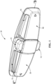
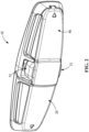
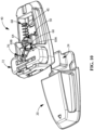
- the shoulder harness buckle assembly 10 comprises a base part 20 and a latch part 40, each configured for with openings 21, 41 to slidingly receive respective right and left shoulder harness straps in a manner allowing vertical adjustment of the buckle assembly on the straps when in use. Operably connecting the base and latch parts joins the straps and inhibits lateral separation thereof and improves restraining capability of the harness.
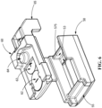
- the base part 20 includes base surface 22 having a post 24 extending upwardly therefrom and an adjacent backstop structure 23 spaced apart from the post.
- a first fixing flange 26 extends outwardly from a side surface the post.
- a second fixing flange 27 extends outwardly from a surface of the backstop structure.
- the fixing flanges are each arranged to extend in the same direction from their respective surfaces and are both spaced apart from the base surface.
- the fixing flanges each include a locking surface 262, 272 and a guiding surface 264, 274.
- a first magnetic element 32 is disposed in a distal end of the post.
- the first magnetic element has a first polarity that is aligned to magnetically attract or repel other magnetic elements adjacently positioned, the magnetic forces acting along an axis generally perpendicularly to the base surface.
- the latch part 40 includes a base surface 42 and an opening 44 through which the post 24 of the base part may be received by relative motion generally perpendicular to the respective base planes of the base and latch parts, referred to as an engagement axis 100.
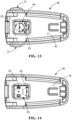
- the latch part 40 further includes a first guide structure 45 proximate to the opening configured to constrain motion of a slide assembly 90 to bi-directionally along a slide axis 110 between opposing latched ( FIG. 9 ) and unlatched ( FIG. 10 ) positions and allow the slide assembly to interact with the post structure engaged in the opening.
- Slide axis 110 is generally longitudinally aligned with the buckle assembly 10.
- Slide assembly 90 is configured to selectively engage fixing flanges 26, 27 on the base part to operably connect the latching portion to the base part when the slide assembly is in the latched position. Displacing the slide assembly to the unlatched position allows the base part to the separated from the latch part to facilitate separation of harness straps for removal of an infant occupant from the safety seat.
- Slide assembly 90 may comprise a catch slide 50, a magnetic slide 60, and an actuator 70 for selectively releasing the harness buckle assembly 10 so that the base part 20 and latch part 40 may be separated.
- Catch slide 50 is configured to retain the base and latch parts connected when the buckle assembly is operably connected.
- Magnetic slide 60 is configured to move the catch slide in a releasing direction to permit separation of the base and latch parts, and to reposition magnetic elements contained therein to either attract or repel the first magnetic element, dependent upon the position of the magnetic slide.
- Catch slide 50 and magnetic slide 60 are moveable in relation to one another. Resilient elements are provided to bias both slides toward their respective latched/engaged positions.
- catch slide 50 is configured with an opening 52 through which post 24 may be extended and includes first and second catch structures 53, 55 that are configured to matingly engage the first and second fixing flange locking surfaces 262, 272 when the catch slide 50 is in the latched position, the first and second catch structures 53, 55 disengaging the first and second fixing flange locking surfaces 262, 272 when the catch slide is moved toward the unlatched position.
- a first resilient element 58 is provided to bias the position of the catch slide 50 toward the latched position while allowing catch slide movement toward the unlatched position as the base and latch parts 20, 40 of the buckle are moved toward a connected configuration, displacement of the catch slide 50 caused by contact between the catch structures 53, 55 and the engaging guide structures 264, 274 on the fixing flanges 26, 27 and the buckle portions are moved into engagement.
- the first resilient element is configured with a relatively low spring rate compared to the spring rate of the second resilient element to minimize resistive force when engaging the latch parts.
- fixing flanges 26, 27 may be oriented laterally from the post 24 and the first and second catch structures 53, 55 on the catch slide 50 be configured to engage the lateral sides of the post. This configuration may be less ideal as greater displacement of the catch slide 50 is necessary to fully disengage the latch assembly and the buckle bending strength, when latched, is reduced compared to other catch structure orientations.
- the catch slide 50 may include a second guide structure 57 which constrains motion of a magnetic slide 60 to bi-directional in a plane parallel to the base plane between opposing engaging ( FIG. 8 ) and releasing positions ( FIG. 9 ).
- a driving structure 65 on the magnetic slide engages ends of the second guide structure 57 in a manner limiting movement of the magnetic slide that may occur without corresponding movement of the catch slide within the first guide structure 45. Once the driving structure 65 contacts a driving end 575 of the latch guide structure, continued movement of the magnetic slide also causes the catch slide to move.
- the magnetic slide 60 includes a second magnetic element 62 and a third magnetic element 63.
- the second and third magnetic elements 62, 63 have second and third polarities, respectively, aligned to act generally perpendicularly to the base plane.
- the first and second polarities are configured to create an attractive force between the magnetic elements while the first and third polarities are configured to create a repulsive force between the magnetic elements.
- a second resilient element 68 is provided to bias the magnetic slide toward the engaging position.
- the second resilient element is configured with a relatively high spring rate compared to the spring rate of the first resilient element to minimize the likelihood of an accidental release of the buckle.
- An actuator 70 is provided to act on the magnetic slide 60 to selectively urge it toward the releasing position. Initial movement of the magnetic slide toward the releasing position does not result in movement of the catch slide as the magnetic slide moves within the limits of the second guide structure 57. Once the travel limiter 65 of the magnetic slide contacts the end 575 of the second guide structure 57, continued movement of the actuator 70 acting on the magnetic slide 60 causes the catch slide 50 to begin moving from the latched position toward the unlatched position. The initial movement of the magnetic slide is necessary to realign the magnetic elements which requires greater slide displacement in relation to the latch part than does the catch slide to disengage the catch structures 53, 55 from the post fixing flanges 26, 27.
- the magnetic slide 60 When releasing the harness buckle, the magnetic slide 60 is shifted by the actuator 70 toward the disengaged position. As the magnetic slide begins moving, the second magnetic 62 element is moved from alignment with the first magnetic element 32 thereby reducing the attractive force.
- the third magnetic element 63 is positioned on the magnetic slide 60 adjacent to the second magnetic element and is simultaneously moved toward alignment with the first magnetic element 32 as the magnetic slide moves. As the first and third magnetic elements begin to move into a magnetically repelling alignment, the magnetic slide 60 reaches the limit of the second guide structure 57. Continued movement of the magnetic slide 60 from this intermediate position via the actuator 70 causes the catch slide 50 to move from the latched position toward the unlatched position.
- the catch structures 53, 55 and the post fixing flanges 26, 27 move out of engagement thereby allowing disengaging movement of the post 24 along the engagement axis 100.
- the repelling force between the first and third magnetic elements urges the post, once the catch surfaces and the engaging structures are disengaged, out of the opening in the latch part thereby separating the latch part from the base part and disconnecting the harness buckle.
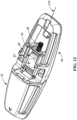
- FIGS. 11 and 12 provide a view of the base surface 42 of the latch part 40 showing the relative positioning of the second and third magnetic elements 62, 63 as the magnetic slide 60 is displaced.
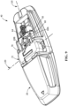
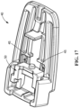
- One embodiment of the actuator 70 includes a pair of opposing release buttons 72, each moveable along a first actuator axis 120 that is perpendicular to the axis along with the magnetic slide moves. Pressing the release buttons 72 inwardly urges the magnetic slide 60 to displace it from the engaged position. Motion of the release buttons 72 may be transferred to the magnetic slide by a cam arrangement or a linkage. In the illustrated embodiment, inward movement of release buttons 72 acts upon the link elements 69A, 69B which are anchored to magnetic slid 60 at post 64. The free ends engage the respective release buttons while coiled end of the link element encircle post 64.
- link elements 69A, 69B Inward displacement of the free ends of link elements 69A, 69B by release button 72 forces post 64 rearwardly toward the disengaged position, acting against the bias force of second resilient member 68 to release the buckle.
- link elements 69A, 69B are joined at the loop encircling post 64 to form a torsion spring configured to bias release buttons 72 outwardly. Inward displacement of the release buttons forces the coiled portion rearwardly to displace the magnetic slide.
- the arrangement of the torsion spring also provides a biasing force on the magnetic slide similar to that provided by the second resilient member 68, allowing the torsion spring to function as the second resilient member 68.
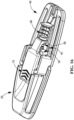
- an actuator release button 75 may be configured for movement along the same axis as the magnetic slide.
- the release button may be a separate construct from the magnetic slide, or it may be integral to the magnetic slide structure. Pressing or pushing the release button causes the magnetic slide to move from its engaged position toward the disengaged position and eventually leads to displacement of the catch slide as described above.
Landscapes
- Engineering & Computer Science (AREA)
- Mechanical Engineering (AREA)
- Health & Medical Sciences (AREA)
- Child & Adolescent Psychology (AREA)
- General Health & Medical Sciences (AREA)
- Aviation & Aerospace Engineering (AREA)
- Transportation (AREA)
- Automotive Seat Belt Assembly (AREA)
- Seats For Vehicles (AREA)
Applications Claiming Priority (2)
| Application Number | Priority Date | Filing Date | Title |
|---|---|---|---|
| US202163293325P | 2021-12-23 | 2021-12-23 | |
| US17/975,096 US11945344B2 (en) | 2021-12-23 | 2022-10-27 | Magnetic shoulder harness buckle for a child restraint |
Publications (2)
| Publication Number | Publication Date |
|---|---|
| EP4201248A1 EP4201248A1 (en) | 2023-06-28 |
| EP4201248B1 true EP4201248B1 (en) | 2024-07-24 |
Family
ID=84389135
Family Applications (1)
| Application Number | Title | Priority Date | Filing Date |
|---|---|---|---|
| EP22211428.2A Active EP4201248B1 (en) | 2021-12-23 | 2022-12-05 | Magnetic shoulder harness buckle for a child restraint |
Country Status (4)
| Country | Link |
|---|---|
| US (2) | US11945344B2 (pl) |
| EP (1) | EP4201248B1 (pl) |
| CN (2) | CN118876890A (pl) |
| PL (1) | PL4201248T3 (pl) |
Families Citing this family (4)
| Publication number | Priority date | Publication date | Assignee | Title |
|---|---|---|---|---|
| KR102450616B1 (ko) * | 2019-06-06 | 2022-10-05 | 원더랜드 스위처랜드 아게 | 자기 버클 어셈블리 |
| USD1116783S1 (en) * | 2023-04-14 | 2026-03-10 | Fidlock Gmbh | Coupler |
| US12329251B2 (en) * | 2023-07-10 | 2025-06-17 | Yanghui Zheng | Watchband connector |
| CN120284048A (zh) * | 2024-01-11 | 2025-07-11 | 明门(中国)幼童用品有限公司 | 扣具以及儿童安全座椅 |
Family Cites Families (34)
| Publication number | Priority date | Publication date | Assignee | Title |
|---|---|---|---|---|
| US1271650A (en) | 1917-12-06 | 1918-07-09 | Louis Arkin | Fastener. |
| US5868445A (en) | 1995-11-02 | 1999-02-09 | Kaufman; Eli | Magnetic slide lock assembly |
| ATE273831T1 (de) | 2000-03-09 | 2004-09-15 | Airbus Gmbh | Passagiersitz mit sicherheitsmitteln |
| US6763557B2 (en) * | 2002-07-01 | 2004-07-20 | Conax Florida Corporation | Buckle with a buckle release system |
| NL1028677C1 (nl) | 2004-08-02 | 2006-02-06 | Maxi Miliaan Bv | Kinderstoel. |
| JP4520824B2 (ja) | 2004-11-09 | 2010-08-11 | アップリカ・チルドレンズプロダクツ株式会社 | バックル |
| PL2436280T3 (pl) | 2006-07-12 | 2017-12-29 | Fidlock Gmbh | Mechaniczno-magnetyczna konstrukcja łącząca |
| CN201023458Y (zh) | 2006-12-28 | 2008-02-20 | 明门实业股份有限公司 | 安全带装置及具有所述安全带装置的座椅 |
| JP5258206B2 (ja) | 2007-05-25 | 2013-08-07 | コンビ株式会社 | シートベルトの保持構造 |
| US8353544B2 (en) | 2008-01-27 | 2013-01-15 | Fidlock Gmbh | Locking magnet closure |
| US8038214B2 (en) | 2009-02-11 | 2011-10-18 | Cosco Management, Inc. | Harness system for juvenile vehicle seat |
| CN101954897A (zh) | 2009-07-13 | 2011-01-26 | 明门香港股份有限公司 | 儿童汽车椅及其弹性胯带 |
| US8328289B2 (en) | 2009-08-12 | 2012-12-11 | Bruce M Tharp | Belt retaining system for child safety seat |
| DE202010010300U1 (de) | 2009-08-24 | 2010-10-21 | Fidlock Gmbh | Mechanischer Verschluss mit einer Verriegelungsvorrichtung |
| US20110133528A1 (en) | 2009-12-08 | 2011-06-09 | Cristina Francesca Keith | Buckles away |
| US8465102B2 (en) | 2010-03-22 | 2013-06-18 | Brian James Morrissey | Child safety seat magnetic web attachment |
| US8985697B2 (en) | 2011-05-09 | 2015-03-24 | Kelli M. Johnson | Strap restraining system for child care devices |
| US20130015691A1 (en) | 2011-07-15 | 2013-01-17 | Orbit Baby, Inc. | Magnetic buckle retention system |
| US8608246B1 (en) | 2011-11-01 | 2013-12-17 | Adam Teague | Safety belt holder |
| DE102011086960A1 (de) * | 2011-11-23 | 2013-05-23 | Fidlock Gmbh | Verschlussvorrichtung |
| US20130285424A1 (en) | 2012-04-25 | 2013-10-31 | Mallory Jo Gardner | Systems and methods for creating a seating or removing space in a child restraint seat |
| US9428143B2 (en) | 2013-07-26 | 2016-08-30 | Recaro Child Safety Llc | Seat with upwardly projecting harness straps |
| US9616779B2 (en) * | 2014-10-20 | 2017-04-11 | Lear Corporation | Seat assembly having a latch mechanism |
| US9307808B1 (en) | 2015-01-19 | 2016-04-12 | Duraflex Hong Kong Limited | Magnetic buckle assembly |
| TWI584755B (zh) | 2016-11-16 | 2017-06-01 | 倍騰國際股份有限公司 | 磁扣 |
| CA2997481C (en) * | 2017-03-03 | 2019-05-07 | Wonderland Switzerland Ag | Support base for a child safety seat |
| US10640018B2 (en) | 2017-03-08 | 2020-05-05 | Dorel Juvenile Group, Inc. | Child restraint system for juvenile vehicle seat |
| US10457246B2 (en) | 2017-04-12 | 2019-10-29 | Dorel Juvenile Group, Inc. | Child restraint system for juvenile vehicle seat |
| US10874178B2 (en) | 2017-12-07 | 2020-12-29 | Wonderland Switzerland Ag | Magnetic buckling assembly |
| CN119184421A (zh) * | 2018-09-18 | 2024-12-27 | 印第安纳米尔斯生产制造股份有限公司 | 座椅安全带设备和带扣 |
| CN111483511B (zh) * | 2019-01-28 | 2023-04-07 | 纽维尔品牌日本合同会社 | 带座位的育儿器具 |
| KR102559009B1 (ko) | 2019-02-27 | 2023-07-24 | 리엔양 플라스틱(선전) 컴퍼니 리미티드 | 자성 버클 |
| KR102450616B1 (ko) | 2019-06-06 | 2022-10-05 | 원더랜드 스위처랜드 아게 | 자기 버클 어셈블리 |
| CN112237315B (zh) * | 2019-07-17 | 2023-09-29 | 明门瑞士股份有限公司 | 扣具 |
-
2022
- 2022-10-27 US US17/975,096 patent/US11945344B2/en active Active
- 2022-12-05 PL PL22211428.2T patent/PL4201248T3/pl unknown
- 2022-12-05 EP EP22211428.2A patent/EP4201248B1/en active Active
- 2022-12-23 CN CN202410854518.5A patent/CN118876890A/zh active Pending
- 2022-12-23 CN CN202211660958.4A patent/CN116326890B/zh active Active
-
2024
- 2024-02-28 US US18/590,239 patent/US20240208374A1/en active Pending
Also Published As
| Publication number | Publication date |
|---|---|
| PL4201248T3 (pl) | 2024-11-18 |
| EP4201248A1 (en) | 2023-06-28 |
| CN116326890B (zh) | 2024-10-22 |
| CN116326890A (zh) | 2023-06-27 |
| US20240208374A1 (en) | 2024-06-27 |
| US11945344B2 (en) | 2024-04-02 |
| US20230202358A1 (en) | 2023-06-29 |
| CN118876890A (zh) | 2024-11-01 |
Similar Documents
| Publication | Publication Date | Title |
|---|---|---|
| EP4201248B1 (en) | Magnetic shoulder harness buckle for a child restraint | |
| EP4042896B1 (en) | A buckle | |
| US12599200B2 (en) | Magnetic buckle assembly | |
| CN101670797B (zh) | 儿童安全座椅 | |
| US5269051A (en) | Buckle assembly | |
| US20100244543A1 (en) | Harness Buckle and Chest Clip Release | |
| EP3821748B1 (en) | Buckle assembly | |
| US7117568B2 (en) | Buckle assembly | |
| GB2518465A (en) | Safety belt buckle | |
| CN218390031U (zh) | 一种磁力扣具 | |
| US11317736B2 (en) | Child care equipment with seat | |
| US3200463A (en) | Quick-release connector | |
| US7600302B2 (en) | Safety buckle for child seat and the like | |
| US8938865B2 (en) | Buckle for restraint belts, particularly for car safety seats for children | |
| US7681288B1 (en) | Structure and material for a child resistant buckle | |
| AU2024246875A1 (en) | Buckle assembly | |
| US20250381930A1 (en) | Buckle | |
| TW202612604A (zh) | 扣具 |
Legal Events
| Date | Code | Title | Description |
|---|---|---|---|
| PUAI | Public reference made under article 153(3) epc to a published international application that has entered the european phase |
Free format text: ORIGINAL CODE: 0009012 |
|
| STAA | Information on the status of an ep patent application or granted ep patent |
Free format text: STATUS: THE APPLICATION HAS BEEN PUBLISHED |
|
| AK | Designated contracting states |
Kind code of ref document: A1 Designated state(s): AL AT BE BG CH CY CZ DE DK EE ES FI FR GB GR HR HU IE IS IT LI LT LU LV MC ME MK MT NL NO PL PT RO RS SE SI SK SM TR |
|
| STAA | Information on the status of an ep patent application or granted ep patent |
Free format text: STATUS: REQUEST FOR EXAMINATION WAS MADE |
|
| 17P | Request for examination filed |
Effective date: 20231222 |
|
| RBV | Designated contracting states (corrected) |
Designated state(s): AL AT BE BG CH CY CZ DE DK EE ES FI FR GB GR HR HU IE IS IT LI LT LU LV MC ME MK MT NL NO PL PT RO RS SE SI SK SM TR |
|
| GRAJ | Information related to disapproval of communication of intention to grant by the applicant or resumption of examination proceedings by the epo deleted |
Free format text: ORIGINAL CODE: EPIDOSDIGR1 |
|
| STAA | Information on the status of an ep patent application or granted ep patent |
Free format text: STATUS: GRANT OF PATENT IS INTENDED |
|
| GRAP | Despatch of communication of intention to grant a patent |
Free format text: ORIGINAL CODE: EPIDOSNIGR1 |
|
| INTG | Intention to grant announced |
Effective date: 20240315 |
|
| GRAS | Grant fee paid |
Free format text: ORIGINAL CODE: EPIDOSNIGR3 |
|
| GRAA | (expected) grant |
Free format text: ORIGINAL CODE: 0009210 |
|
| STAA | Information on the status of an ep patent application or granted ep patent |
Free format text: STATUS: THE PATENT HAS BEEN GRANTED |
|
| AK | Designated contracting states |
Kind code of ref document: B1 Designated state(s): AL AT BE BG CH CY CZ DE DK EE ES FI FR GB GR HR HU IE IS IT LI LT LU LV MC ME MK MT NL NO PL PT RO RS SE SI SK SM TR |
|
| REG | Reference to a national code |
Ref country code: GB Ref legal event code: FG4D |
|
| REG | Reference to a national code |
Ref country code: CH Ref legal event code: EP |
|
| REG | Reference to a national code |
Ref country code: IE Ref legal event code: FG4D Ref country code: DE Ref legal event code: R096 Ref document number: 602022004817 Country of ref document: DE |
|
| REG | Reference to a national code |
Ref country code: LT Ref legal event code: MG9D |
|
| P01 | Opt-out of the competence of the unified patent court (upc) registered |
Free format text: CASE NUMBER: APP_54780/2024 Effective date: 20241004 |
|
| REG | Reference to a national code |
Ref country code: NL Ref legal event code: MP Effective date: 20240724 |
|
| PG25 | Lapsed in a contracting state [announced via postgrant information from national office to epo] |
Ref country code: PT Free format text: LAPSE BECAUSE OF FAILURE TO SUBMIT A TRANSLATION OF THE DESCRIPTION OR TO PAY THE FEE WITHIN THE PRESCRIBED TIME-LIMIT Effective date: 20241125 |
|
| REG | Reference to a national code |
Ref country code: AT Ref legal event code: MK05 Ref document number: 1705427 Country of ref document: AT Kind code of ref document: T Effective date: 20240724 |
|
| PG25 | Lapsed in a contracting state [announced via postgrant information from national office to epo] |
Ref country code: NL Free format text: LAPSE BECAUSE OF FAILURE TO SUBMIT A TRANSLATION OF THE DESCRIPTION OR TO PAY THE FEE WITHIN THE PRESCRIBED TIME-LIMIT Effective date: 20240724 |
|
| PG25 | Lapsed in a contracting state [announced via postgrant information from national office to epo] |
Ref country code: PT Free format text: LAPSE BECAUSE OF FAILURE TO SUBMIT A TRANSLATION OF THE DESCRIPTION OR TO PAY THE FEE WITHIN THE PRESCRIBED TIME-LIMIT Effective date: 20241125 Ref country code: NL Free format text: LAPSE BECAUSE OF FAILURE TO SUBMIT A TRANSLATION OF THE DESCRIPTION OR TO PAY THE FEE WITHIN THE PRESCRIBED TIME-LIMIT Effective date: 20240724 |
|
| PGFP | Annual fee paid to national office [announced via postgrant information from national office to epo] |
Ref country code: DE Payment date: 20241210 Year of fee payment: 3 |
|
| PG25 | Lapsed in a contracting state [announced via postgrant information from national office to epo] |
Ref country code: NO Free format text: LAPSE BECAUSE OF FAILURE TO SUBMIT A TRANSLATION OF THE DESCRIPTION OR TO PAY THE FEE WITHIN THE PRESCRIBED TIME-LIMIT Effective date: 20241024 |
|
| PG25 | Lapsed in a contracting state [announced via postgrant information from national office to epo] |
Ref country code: FI Free format text: LAPSE BECAUSE OF FAILURE TO SUBMIT A TRANSLATION OF THE DESCRIPTION OR TO PAY THE FEE WITHIN THE PRESCRIBED TIME-LIMIT Effective date: 20240724 Ref country code: GR Free format text: LAPSE BECAUSE OF FAILURE TO SUBMIT A TRANSLATION OF THE DESCRIPTION OR TO PAY THE FEE WITHIN THE PRESCRIBED TIME-LIMIT Effective date: 20241025 |
|
| PGFP | Annual fee paid to national office [announced via postgrant information from national office to epo] |
Ref country code: PL Payment date: 20241203 Year of fee payment: 3 |
|
| PG25 | Lapsed in a contracting state [announced via postgrant information from national office to epo] |
Ref country code: BG Free format text: LAPSE BECAUSE OF FAILURE TO SUBMIT A TRANSLATION OF THE DESCRIPTION OR TO PAY THE FEE WITHIN THE PRESCRIBED TIME-LIMIT Effective date: 20240724 |
|
| PGFP | Annual fee paid to national office [announced via postgrant information from national office to epo] |
Ref country code: FR Payment date: 20241227 Year of fee payment: 3 |
|
| PG25 | Lapsed in a contracting state [announced via postgrant information from national office to epo] |
Ref country code: LV Free format text: LAPSE BECAUSE OF FAILURE TO SUBMIT A TRANSLATION OF THE DESCRIPTION OR TO PAY THE FEE WITHIN THE PRESCRIBED TIME-LIMIT Effective date: 20240724 |
|
| PG25 | Lapsed in a contracting state [announced via postgrant information from national office to epo] |
Ref country code: IS Free format text: LAPSE BECAUSE OF FAILURE TO SUBMIT A TRANSLATION OF THE DESCRIPTION OR TO PAY THE FEE WITHIN THE PRESCRIBED TIME-LIMIT Effective date: 20241124 Ref country code: AT Free format text: LAPSE BECAUSE OF FAILURE TO SUBMIT A TRANSLATION OF THE DESCRIPTION OR TO PAY THE FEE WITHIN THE PRESCRIBED TIME-LIMIT Effective date: 20240724 |
|
| PG25 | Lapsed in a contracting state [announced via postgrant information from national office to epo] |
Ref country code: HR Free format text: LAPSE BECAUSE OF FAILURE TO SUBMIT A TRANSLATION OF THE DESCRIPTION OR TO PAY THE FEE WITHIN THE PRESCRIBED TIME-LIMIT Effective date: 20240724 |
|
| PG25 | Lapsed in a contracting state [announced via postgrant information from national office to epo] |
Ref country code: RS Free format text: LAPSE BECAUSE OF FAILURE TO SUBMIT A TRANSLATION OF THE DESCRIPTION OR TO PAY THE FEE WITHIN THE PRESCRIBED TIME-LIMIT Effective date: 20241024 Ref country code: ES Free format text: LAPSE BECAUSE OF FAILURE TO SUBMIT A TRANSLATION OF THE DESCRIPTION OR TO PAY THE FEE WITHIN THE PRESCRIBED TIME-LIMIT Effective date: 20240724 |
|
| PG25 | Lapsed in a contracting state [announced via postgrant information from national office to epo] |
Ref country code: RS Free format text: LAPSE BECAUSE OF FAILURE TO SUBMIT A TRANSLATION OF THE DESCRIPTION OR TO PAY THE FEE WITHIN THE PRESCRIBED TIME-LIMIT Effective date: 20241024 Ref country code: NO Free format text: LAPSE BECAUSE OF FAILURE TO SUBMIT A TRANSLATION OF THE DESCRIPTION OR TO PAY THE FEE WITHIN THE PRESCRIBED TIME-LIMIT Effective date: 20241024 Ref country code: LV Free format text: LAPSE BECAUSE OF FAILURE TO SUBMIT A TRANSLATION OF THE DESCRIPTION OR TO PAY THE FEE WITHIN THE PRESCRIBED TIME-LIMIT Effective date: 20240724 Ref country code: IS Free format text: LAPSE BECAUSE OF FAILURE TO SUBMIT A TRANSLATION OF THE DESCRIPTION OR TO PAY THE FEE WITHIN THE PRESCRIBED TIME-LIMIT Effective date: 20241124 Ref country code: HR Free format text: LAPSE BECAUSE OF FAILURE TO SUBMIT A TRANSLATION OF THE DESCRIPTION OR TO PAY THE FEE WITHIN THE PRESCRIBED TIME-LIMIT Effective date: 20240724 Ref country code: GR Free format text: LAPSE BECAUSE OF FAILURE TO SUBMIT A TRANSLATION OF THE DESCRIPTION OR TO PAY THE FEE WITHIN THE PRESCRIBED TIME-LIMIT Effective date: 20241025 Ref country code: FI Free format text: LAPSE BECAUSE OF FAILURE TO SUBMIT A TRANSLATION OF THE DESCRIPTION OR TO PAY THE FEE WITHIN THE PRESCRIBED TIME-LIMIT Effective date: 20240724 Ref country code: ES Free format text: LAPSE BECAUSE OF FAILURE TO SUBMIT A TRANSLATION OF THE DESCRIPTION OR TO PAY THE FEE WITHIN THE PRESCRIBED TIME-LIMIT Effective date: 20240724 Ref country code: BG Free format text: LAPSE BECAUSE OF FAILURE TO SUBMIT A TRANSLATION OF THE DESCRIPTION OR TO PAY THE FEE WITHIN THE PRESCRIBED TIME-LIMIT Effective date: 20240724 Ref country code: AT Free format text: LAPSE BECAUSE OF FAILURE TO SUBMIT A TRANSLATION OF THE DESCRIPTION OR TO PAY THE FEE WITHIN THE PRESCRIBED TIME-LIMIT Effective date: 20240724 |
|
| PGFP | Annual fee paid to national office [announced via postgrant information from national office to epo] |
Ref country code: TR Payment date: 20241129 Year of fee payment: 3 |
|
| PG25 | Lapsed in a contracting state [announced via postgrant information from national office to epo] |
Ref country code: SM Free format text: LAPSE BECAUSE OF FAILURE TO SUBMIT A TRANSLATION OF THE DESCRIPTION OR TO PAY THE FEE WITHIN THE PRESCRIBED TIME-LIMIT Effective date: 20240724 Ref country code: DK Free format text: LAPSE BECAUSE OF FAILURE TO SUBMIT A TRANSLATION OF THE DESCRIPTION OR TO PAY THE FEE WITHIN THE PRESCRIBED TIME-LIMIT Effective date: 20240724 Ref country code: RO Free format text: LAPSE BECAUSE OF FAILURE TO SUBMIT A TRANSLATION OF THE DESCRIPTION OR TO PAY THE FEE WITHIN THE PRESCRIBED TIME-LIMIT Effective date: 20240724 |
|
| PG25 | Lapsed in a contracting state [announced via postgrant information from national office to epo] |
Ref country code: EE Free format text: LAPSE BECAUSE OF FAILURE TO SUBMIT A TRANSLATION OF THE DESCRIPTION OR TO PAY THE FEE WITHIN THE PRESCRIBED TIME-LIMIT Effective date: 20240724 |
|
| PG25 | Lapsed in a contracting state [announced via postgrant information from national office to epo] |
Ref country code: CZ Free format text: LAPSE BECAUSE OF FAILURE TO SUBMIT A TRANSLATION OF THE DESCRIPTION OR TO PAY THE FEE WITHIN THE PRESCRIBED TIME-LIMIT Effective date: 20240724 |
|
| REG | Reference to a national code |
Ref country code: DE Ref legal event code: R097 Ref document number: 602022004817 Country of ref document: DE |
|
| PG25 | Lapsed in a contracting state [announced via postgrant information from national office to epo] |
Ref country code: SK Free format text: LAPSE BECAUSE OF FAILURE TO SUBMIT A TRANSLATION OF THE DESCRIPTION OR TO PAY THE FEE WITHIN THE PRESCRIBED TIME-LIMIT Effective date: 20240724 |
|
| PLBE | No opposition filed within time limit |
Free format text: ORIGINAL CODE: 0009261 |
|
| STAA | Information on the status of an ep patent application or granted ep patent |
Free format text: STATUS: NO OPPOSITION FILED WITHIN TIME LIMIT |
|
| 26N | No opposition filed |
Effective date: 20250425 |
|
| PG25 | Lapsed in a contracting state [announced via postgrant information from national office to epo] |
Ref country code: MC Free format text: LAPSE BECAUSE OF FAILURE TO SUBMIT A TRANSLATION OF THE DESCRIPTION OR TO PAY THE FEE WITHIN THE PRESCRIBED TIME-LIMIT Effective date: 20240724 |
|
| PG25 | Lapsed in a contracting state [announced via postgrant information from national office to epo] |
Ref country code: LU Free format text: LAPSE BECAUSE OF NON-PAYMENT OF DUE FEES Effective date: 20241205 |
|
| PG25 | Lapsed in a contracting state [announced via postgrant information from national office to epo] |
Ref country code: SE Free format text: LAPSE BECAUSE OF FAILURE TO SUBMIT A TRANSLATION OF THE DESCRIPTION OR TO PAY THE FEE WITHIN THE PRESCRIBED TIME-LIMIT Effective date: 20240724 |
|
| REG | Reference to a national code |
Ref country code: BE Ref legal event code: MM Effective date: 20241231 |
|
| PG25 | Lapsed in a contracting state [announced via postgrant information from national office to epo] |
Ref country code: BE Free format text: LAPSE BECAUSE OF NON-PAYMENT OF DUE FEES Effective date: 20241231 |
|
| PG25 | Lapsed in a contracting state [announced via postgrant information from national office to epo] |
Ref country code: IE Free format text: LAPSE BECAUSE OF NON-PAYMENT OF DUE FEES Effective date: 20241205 |
|
| PG25 | Lapsed in a contracting state [announced via postgrant information from national office to epo] |
Ref country code: CY Free format text: LAPSE BECAUSE OF FAILURE TO SUBMIT A TRANSLATION OF THE DESCRIPTION OR TO PAY THE FEE WITHIN THE PRESCRIBED TIME-LIMIT; INVALID AB INITIO Effective date: 20221205 |
|
| PGFP | Annual fee paid to national office [announced via postgrant information from national office to epo] |
Ref country code: IT Payment date: 20251231 Year of fee payment: 4 |