EP4200243B1 - Ergonomisches hubsystem - Google Patents
Ergonomisches hubsystem Download PDFInfo
- Publication number
- EP4200243B1 EP4200243B1 EP21925091.7A EP21925091A EP4200243B1 EP 4200243 B1 EP4200243 B1 EP 4200243B1 EP 21925091 A EP21925091 A EP 21925091A EP 4200243 B1 EP4200243 B1 EP 4200243B1
- Authority
- EP
- European Patent Office
- Prior art keywords
- load
- handle
- lifting
- drum
- ergonomic
- Prior art date
- Legal status (The legal status is an assumption and is not a legal conclusion. Google has not performed a legal analysis and makes no representation as to the accuracy of the status listed.)
- Active
Links
Images


Classifications
-
- B—PERFORMING OPERATIONS; TRANSPORTING
- B66—HOISTING; LIFTING; HAULING
- B66D—CAPSTANS; WINCHES; TACKLES, e.g. PULLEY BLOCKS; HOISTS
- B66D3/00—Portable or mobile lifting or hauling appliances
- B66D3/18—Power-operated hoists
- B66D3/20—Power-operated hoists with driving motor, e.g. electric motor, and drum or barrel contained in a common housing
-
- B—PERFORMING OPERATIONS; TRANSPORTING
- B66—HOISTING; LIFTING; HAULING
- B66D—CAPSTANS; WINCHES; TACKLES, e.g. PULLEY BLOCKS; HOISTS
- B66D1/00—Rope, cable, or chain winding mechanisms; Capstans
- B66D1/28—Other constructional details
- B66D1/36—Guiding, or otherwise ensuring winding in an orderly manner, of ropes, cables, or chains
- B66D1/38—Guiding, or otherwise ensuring winding in an orderly manner, of ropes, cables, or chains by means of guides movable relative to drum or barrel
-
- B—PERFORMING OPERATIONS; TRANSPORTING
- B66—HOISTING; LIFTING; HAULING
- B66D—CAPSTANS; WINCHES; TACKLES, e.g. PULLEY BLOCKS; HOISTS
- B66D1/00—Rope, cable, or chain winding mechanisms; Capstans
- B66D1/54—Safety gear
-
- B—PERFORMING OPERATIONS; TRANSPORTING
- B66—HOISTING; LIFTING; HAULING
- B66D—CAPSTANS; WINCHES; TACKLES, e.g. PULLEY BLOCKS; HOISTS
- B66D3/00—Portable or mobile lifting or hauling appliances
- B66D3/18—Power-operated hoists
-
- B—PERFORMING OPERATIONS; TRANSPORTING
- B66—HOISTING; LIFTING; HAULING
- B66D—CAPSTANS; WINCHES; TACKLES, e.g. PULLEY BLOCKS; HOISTS
- B66D3/00—Portable or mobile lifting or hauling appliances
- B66D3/18—Power-operated hoists
- B66D3/24—Applications of limit switches
Definitions
- the invention relates to an ergonomic lifting system used to move any load from one position to another by applying a small amount of force with human touch.
- the invention particularly relates to an ergonomic lifting system designed to place the load cell in the lifting interface, which is directly connected to the load with the hook and allows the user to move the load in the direction he wants by moving the handle on the lifting interface up and down, or by touching the lifted load and applying force up and down.
- manipulators used to move any load from one location to another by balancing the weight of the load.
- the main purpose of the manipulators is to ensure that required handling operation is completed by the operator with little effort.
- Manipulators are divided into electrical and pneumatic systems.
- Pneumatic systems are systems that have been used for a long time in the current art and have a certain reliability and volume.
- Electric systems focus on solving the problems of pneumatic systems and came up with a new handle and rope systems compared to the grippers used in pneumatic systems. Thanks to the new handle design used in electrical systems, sensitive and ergonomic solutions have been achieved.
- the handles used in electrical systems are divided into two as load control can be done by touching and without touching the load.
- the handles, which allow touching the load are divided into two as movable and fixed. In fixed handles, the user cannot be given an accurate control sensitivity and ergonomics due to the fact that the handle is not movable. There are incomplete and faulty solutions in systems with movable handles. In the first of these solutions, there is a possibility that the value read on the load cell may not reflect the truth, since the load cell is not in the lifting interface part.
- the system is affected by the magnetic field in the environment in which it is used.
- different sensitivity and response are encountered in different directions because the movable handle moves in different lengths in the up and down directions. In this case, it is possible for the user to receive false feedback in different directions.
- the probability of the system to be diverted from its middle position increases, and since the whole process is carried out with a single spring, the error rate increases as the life of the spring decreases.
- the sliding movement of the handle is not healthy.
- Patents found in the literature related to ergonomic lifting system are provided below.
- ITUD20040226 relates to an apparatus for lifting and carrying loads.
- Said apparatus basically consists of a beam connected by two rods equipped with a pair of wheels and a pair that can slide along the rails perpendicular to each beam.
- a slider which is moved along the beam in two directions by means of a reversing motor, is connected to the beam.
- the slider is associated with a control device which is equipped with a crane-like lifting element associated with a cable containing a hook and can be managed by the operator via the cable.
- the control device is connected to an electronic control unit that can selectively operate the motor and reversing motor to slide the beam along the rails and the slider.
- Said control device comprises a housing body through which the cable passes vertically and in which four wheels are mounted at an angle of 90°to each other.
- the pins or shafts of said wheels are mounted at the end of the load cells fixed inside the housing body.
- Each load cell senses the force transmitted to the corresponding wheel by the cable moved to an inclined position and sends an electrical output signal proportional to the said force to the management and control unit of the motors.
- the lower end of the cable has a handle for the operator to manage the controller.
- the load cells inside the control device transmit a relative signal to the management and control unit of the motors, and the movement of the beam and/or slider to relocate the object can be done.
- the load cells that sense the load force are not in the handle, there is a possibility that the value read in the load cell may not reflect the real value.
- the handle system is not movable, manual control is not ergonomic. This leads to the inadequacy to obtain a stable system with the desired sensitivity.
- US6386513 relates to a human power amplifier for lifting load.
- it includes an end effector that is gripped by the operator and attached to the load.
- the end effector is connected by a rope, wire, cable, belt to a pulley or a drum driven by an actuator to raise or lower the load.
- the end effector includes a force sensor that measures the vertical force exerted by the operator on the end effector and transmits a signal to a controller.
- the controller and actuator are configured so that a predetermined percentage of the force required to raise or lower the load is applied by the actuator and the remaining force is provided by the operator.
- the controller controlling the operation of the actuator is programmed to respond to the first signal from the sensor representing the force exerted by the operator and the second signal representing the pulling force on the line, causing the actuator to rotate the pulley to raise and lower the line.
- the possibility of the system to be incorrectly in the middle position increases due to the use of one spring in the end effector, and since the whole process is carried out with a single spring, the error rate increases as the life of the spring decreases.
- US6622990 relates to a human power amplifier for lifting load.
- it includes an end effector that is gripped by the operator and attached to the load.
- the end effector is connected by a rope, wire, cable, belt to a pulley or a drum driven by an actuator to raise or lower the load.
- the end effector includes a force sensor that measures the vertical force exerted by the operator on the end effector and transmits a signal to a controller.
- the controller and actuator are configured so that a predetermined percentage of the force required to raise or lower the load is applied by the actuator and the remaining force is provided by the operator.
- the controller of the present invention is designed to have an output terminal for controlling the rotational speed of the pulley as a function of the first and second signals.
- the possibility of the system to be incorrectly in the middle position increases due to the use of one spring in the end effector, and since the whole process is carried out with a single spring, the error rate increases as the life of the spring decreases.
- US6886812 relates to a human power amplifier for lifting load.
- it includes an end effector that is gripped by the operator and attached to the load.
- the end effector is connected by a rope, wire, cable, belt to a pulley or a drum driven by an actuator to raise or lower the load.
- the end effector includes a force sensor that measures the vertical force exerted by the operator on the end effector and transmits a signal to a controller.
- the controller and actuator are configured so that a predetermined percentage of the force required to raise or lower the load is applied by the actuator and the remaining force is provided by the operator.
- a load force estimator is used to estimate the operator input not close to the end effector, which sends a signal to the controller to estimate the force applied by the operator, and the controller's estimated load force signal and the force signal applied by the operator are used. It is provided to control the actuator as a function.
- the possibility of the system to be inaccurate to the middle position increases due to the use of one spring in the end effector, and since the whole process is carried out with a single spring, the error rate increases as the life of the spring decreases.
- US7559533 relates to a lifting actuator.
- Said lift actuator basically comprises a controller and a pulley with a cable wound on the actuator to support a load at the free end of a cable.
- Said pulley is driven by a motor and a related transmission.
- a load interface that generates a signal to the controller is connected to the end of said cable.
- the controller allows the actuator to raise and lower the load.
- a load cell was used to sense only a compression force in response to the load applied to the cable.
- Said load cell transmits a load signal to the controller.
- the controller enables actuator operation as a function of the load signal.
- the load cell since the load cell is positioned in the actuator, there is a possibility that the value read on the load cell may not reflect the real value.
- the present invention relates to an ergonomic lifting system that eliminates the disadvantages mentioned above and brings new advantages to the related technical field.
- the main object of the invention is to enable the user to move the load in the desired direction by moving the handle up and down on the lifting interface, or by touching the load and applying force in the up and down direction.
- An object of the invention is to obtain an ergonomic lifting system that contains the load cell in the load interface so that load and the load cell are directly connected.
- Another object of the invention is to obtain ergonomic lifting system that detects linear movement of the handle on the lifting interface with linear potentiometer instead of measuring it with magnetic so that system has a higher resolution with 0.01 mm resolution and is not affected by the magnetic field coming from the external environment.
- Another object of the invention is to obtain a sensitive and safe ergonomic lifting system that allows touching the load and is not magnetically affected by external environments.
- Another object of the invention is to obtain a mechanically long-lasting, stable and reliable ergonomic lifting system by means of linear bearings and springs in the handle.
- the invention comprises a lifting unit containing a motor that controls the up and down movements of the load, a gearbox that increases the amount of torque transmitted from the motor on the motor, and a drum that the wire rope on which the load is carried is wound.
- the lifting system includes a lifting interface comprising, among others,
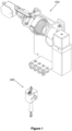
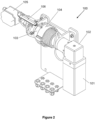
- the ergonomic lifting system in its most basic form; It consists of two parts, the lifting unit (100) and the lifting interface (200), which are connected to each other with a wire rope.
- the lifting unit (100) is basically includes, the motor (101) that controls the up and down moment of the load, the gearbox (102) that increases the torque from the motor (101) on the motor (101), the drum (103) which the load carrying wire rope wrapped that is on the gearbox (102), the turn counter (105) which measures the amount of rope wrapped around the drum or unwrapped from the drum (103) next to the drum (103), and sends a signal to the controller to stop the ergonomic lifting system when the rope reaches the lower and upper limits, the wire rope guide (104), which ensures smooth winding or unwinding of the wire rope during the winding or unwinding of the wire rope on the drum (103), a linear potentiometer (106), which is connected to the wire rope guide (104) and to the drum (103), and provides the measurement of the amount of rope wrapped or released from the drum (103) by measuring the lateral movement of the wire rope guide (104) on the drum (103) in the direction of the drum (103) length.
- the motor (101) that controls the up and down moment of the load
- the load is carried on the lifting unit (100).
- the lifting unit (100) is mounted in different orientations in different places to carry out the lifting and transporting process.
- the motor (101) in the lifting unit (100) provides control of the up and down movement of the load.
- a gearbox (102) on the motor (101) to increase the amount of torque transmitted from the motor (101), a drum (103) on which the rope is wrapped that is connected to the gearbox (102), and a turn counter (105) next to the drum (103).
- the turn counter (105) provides the measurement of the amount of rope wounded around the drum (103) or released from the drum (103) and sending the signal to the controller, which stops the ergonomic lifting system when it reaches the lower or upper lifting limit of the ergonomic lifting system.
- a linear potentiometer (106) is connected to the abovementioned drum (103) and the wire rope guide (104) that provide safe and controlled winding or releasing of the rope that is wound on or released from the drum (103). During these movements, the displacement movements of the wire rope guide (104) are measured by the linear potentiometer (106), and thus the amount of rope wound from the drum (103) or released from the drum (103) can be calculated.
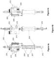
- FIGS 3a and 3b show the lifting interface (200).
- the lifting interface (200) helps the user to control the load that lifted and transported by the lifting unit (100).
- the lifting interface (200) is consist of, the rope connection apparatus (202) that provides the connection of the lifting interface (200) to the lifting unit (100) with the wire rope that wounds on the drum (103), the shell (201) with the rope connection apparatus (202) on the top, the load cell (203), which is connected to the rope connection apparatus (202) from its upper end, passes through the shell (201) on the vertical axis and measures the weight of the lifted load and the force applied by the user to the load and transmits it to the controller, a handle (204) that enables the load to be moved up and down by moving up and down that located under the load cell (203), a linear bearing (205) that supports the handle so that it can move up and down under the load cell (203), the upper spring (206), which brings the handle (204) to its middle position under the load cell (203) after the handle (204), which is moved up or down, is
- FIGs 4a, 4b and 4c show the shell (201) which has a rope connection apparatus (202) on its upper side.
- Said rope connection apparatus (202) provides connection with the lifting interface (200) to the lifting unit (100) by the help of the wire rope that wound on the drum (103).
- a load cell (203) is passed through the shell (201) on the vertical axis and said load cell (203) is connected to the rope connection apparatus (202) from its upper end.
- the load cell (203) measures that the weight of the lifted load and the force applied by the user to the load, and transmit the data to the controller.
- the load is moved up or down by the motor (101).
- the handle (204) is supported by a linear bearing (205) located under the shell (201) so that it can move up and down. Said handle (204) moves up and down under the load cell (203), so that the load can be moved up and down.
- An upper spring (206) is attached to the upper end of the handle (204), which brings the handle (204) to its middle position under the load cell (203) after the user releases the handle (204), which is moved up or down manually by the user, and creates a reaction force for the user during these movements.
- a lower spring (207) is attached to the lower end of the handle (204), which brings the handle (204) to its middle position under the load cell (203) after the user releases the handle (204), which is moved up or down manually by the user, and creates a reaction force for the user during these movements.
- a lower connection apparatus (210) is connected to the bottom of the shell (201), to which apparatus such as hooks carrying the load are attached.
- the working principle of the ergonomic lifting system is as follows; To lift the load for the first, the user connects the load to the lower connection apparatus (210) then holds and moves the handle (204) upward direction. The upward movement of the handle under the load cell (203) is detected by the interface linear potentiometer (209) and transmitted to the controller, and the load is lifted upwards on the ergonomic lifting system by winding the wire rope on the drum (103). While the user's hand is on the handle (204), it is detected by the object sensor (208). The ergonomic lifting system does not move without the user's hand presence.
- the handle (204) The farther the user pulls the handle (204) from its middle position under the load cell (203), the faster the ergonomic lifting system moves the load.
- the upper spring (206) and the lower spring (207) create a reaction force to the user and ensure that the handle (204) is brought to its middle position under the load cell (203). Since the handle (204) is moved by a linear bearing (205) under the load cell (203), the forces of the upper spring (206) and lower spring (207) are transmitted to the user in a proper way.
- the user After the user lifts the load by moving the handle (204), the user activates the floating mode by pressing the floating mode button (2013).
- the load cell (203) reads the weight of the lifted load and transmits it to the controller.
- the user By touching the load, the user changes the weight data read on the load cell and thus the lifted load moves.
- the upward or downward movement of the load determined by the direction of the applied force which read by the load cell (203) that transmitted to controller, by using the motor (101).
- the lifting speed of the load varies as much as the amount of force applied by the user.
- the speed adjustment of the ergonomic lifting system can be done with the speed adjustment button (211).
Landscapes
- Engineering & Computer Science (AREA)
- Mechanical Engineering (AREA)
- Invalid Beds And Related Equipment (AREA)
Claims (8)
- Ergonomisches Hubsystem zum Heben und Tragen beliebiger Lasten durch Anwenden einer geringen Kraft mit menschlicher Berührung, das die Auf- und Ab-Bewegungen der angehobenen Last steuert, umfassend;- eine Hubeinheit (100), die umfasst:• einen Motor (101), der Drehmoment bereitstellt,• ein Getriebe (102), das das Drehmoment vom Motor (101) erhöht,• eine Trommel (103), auf die ein Drahtseil gewickelt ist,• eine Drahtseilführung (104), die sicherstellt, dass das Drahtseil während des Aufwickelns oder Abwickelns des Drahtseils auf der Trommel (103) auf kontrollierte und sichere Weise in die Trommel (103) gewickelt oder von dieser freigegeben wird,- eine Hubschnittstelle (200), die mit der Hubeinheit (100) verbunden ist und umfasst:• eine untere Verbindungsvorrichtung (210), die mit der Unterseite eines Gehäuses (201) verbunden ist, wobei die Last befestigt ist,• eine Seilverbindungsvorrichtung (202), die mit dem auf der Trommel (103) in der Hubschnittstelle (200) aufgewickelten Seil verbunden ist, um dem Benutzer zu ermöglichen, die von der Hubeinheit (100) angehobene und getragene Last zu steuern,• das Gehäuse (201), das mit dem auf der Trommel (103) aufgewickelten Drahtseil mittels der Seilverbindungsvorrichtung (202) auf der Oberseite und mit der unteren Verbindungsvorrichtung (210) auf der Unterseite verbunden ist, wo die die Last tragenden Vorrichtungen verbunden sind,• eine Wägezelle (203), die von ihrem oberen Ende her mit der Seilverbindungsvorrichtung (202) verbunden ist, auf der vertikalen Achse durch das Gehäuse (201) verläuft und das Gewicht der angehobenen Last und die vom Benutzer auf die Last ausgeübte Kraft misst, diese an das Steuergerät überträgt und es ermöglicht, die Last mit Hilfe des Motors (101) auf oder ab zu bewegen,• einen Griff (204), der unter dem Gehäuse (201) montiert ist und es ermöglicht, die Last durch den Benutzer auf und ab zu bewegen, wenn die Hand des Benutzers den Griff (204), der sich unter der Wägezelle (203) befindet, hält und auf und ab bewegt• eine obere Feder (206), die mit dem oberen Ende des Griffs (204) verbunden ist, der auf oder ab bewegt werden kann, bringt den Griff (204) in seine Mittelstellung unter dem Gehäuse (201), nachdem der Benutzer den Griff (204) losgelassen hat, und erzeugt während dieser Bewegungen eine Reaktionskraft für den Benutzer,• eine untere Feder (207), die mit dem unteren Ende des Griffs (204) verbunden ist, der auf oder ab bewegt werden kann, bringt den Griff (204) in seine Mittelstellung unter dem Gehäuse (201), nachdem der Benutzer den Griff (204) losgelassen hat, und erzeugt während dieser Bewegungen eine Reaktionskraft für den Benutzer, wobei das Hubsystem dadurch gekennzeichnet ist, dass die Hubschnittstelle ferner umfasst• ein Schnittstellenlinearpotentiometer (209), das mit dem Gehäuse (201) und dem Griff (204) in Verbindung steht, der sich im Inneren der Lastschnittstelle (200) befindet, erfasst die Auf- und Ab-Bewegung des Griffs (204) und überträgt sie an das Steuergerät und ermöglicht es, die Last durch den Motor (101) auf oder ab zu bewegen,• einen Objektsensor (208), der sich am Gehäuse (201) befindet und erfasst, ob sich die Hand des Benutzers am Griff (204) befindet.
- Ergonomisches Hubsystem gemäß Anspruch 1, dadurch gekennzeichnet, dass die Hubschnittstelle (200) die Wägezelle (203) beinhaltet, die die vom Benutzer durch Berühren der Last ausgeübte Kraft und das Gewicht der angehobenen Last liest und an das Steuergerät überträgt, wobei sich die Auf- und Ab-Bewegungsgeschwindigkeit des ergonomischen Hubsystems gemäß der vom Benutzer auf die Last ausgeübten Kraft ändert.
- Ergonomisches Hubsystem gemäß Anspruch 1, gekennzeichnet durch das Umfassen eines Linearpotentiometers (106), das mit der Drahtseilführung (104) verbunden ist und die Berechnung der auf die Trommel (103) aufgewickelten oder von ihr freigegebenen Seilmenge durch Messen des seitlichen Schlupfs der Drahtseilführung (104) auf der Trommel (103) in Richtung der Länge der Trommel (103) bereitstellt.
- Ergonomisches Hubsystem gemäß Anspruch 1, dadurch gekennzeichnet, dass die Hubschnittstelle (200) einen Geschwindigkeitseinstell-Knopf (211) beinhaltet, der sich am Gehäuse (201) befindet und es ermöglicht, die Geschwindigkeit des ergonomischen Hubsystems einzustellen.
- Ergonomisches Hubsystem gemäß Anspruch 1, dadurch gekennzeichnet, dass die Hubschnittstelle (200) einen Not-Aus-Knopf (212) beinhaltet, der sich am Gehäuse (201) befindet und im Notfall ein Anhalten des ergonomischen Hubsystems ermöglicht.
- Ergonomisches Hubsystem gemäß Anspruch 1, dadurch gekennzeichnet, dass die Hubschnittstelle (200) einen Schwebemodus-Knopf (213) beinhaltet, der sich am Gehäuse (201) befindet und ein Umschalten des ergonomischen Hubsystems in den Schwebemodus ermöglicht.
- Ergonomisches Hubsystem gemäß Anspruch 1, dadurch gekennzeichnet, dass die Hubeinheit (100) einen Umdrehungszähler (105) beinhaltet, der sich neben der Trommel (103) befindet und mit der Trommel (103) verbunden ist und somit die Drehung der Trommel (103) messen kann, sodass die Menge des um die Trommel (103) gewickelten oder von ihr freigegebenen Drahtseils berechnet werden kann, und, wenn das ergonomische Hubsystem die untere oder obere Hubgrenze erreicht, es ein Signal an das Steuergerät sendet, um das ergonomische Hubsystem anzuhalten.
- Ergonomisches Hubsystem gemäß Anspruch 1, gekennzeichnet durch das Umfassen eines Linearlagers (205), das den Griff (204) unter dem Gehäuse (201) trägt, sodass er sich auf und ab bewegen kann.
Applications Claiming Priority (1)
| Application Number | Priority Date | Filing Date | Title |
|---|---|---|---|
| PCT/TR2021/050997 WO2023055309A1 (en) | 2021-09-30 | 2021-09-30 | Ergonomic lifting system |
Publications (4)
| Publication Number | Publication Date |
|---|---|
| EP4200243A1 EP4200243A1 (de) | 2023-06-28 |
| EP4200243A4 EP4200243A4 (de) | 2024-03-06 |
| EP4200243C0 EP4200243C0 (de) | 2024-12-25 |
| EP4200243B1 true EP4200243B1 (de) | 2024-12-25 |
Family
ID=85783341
Family Applications (1)
| Application Number | Title | Priority Date | Filing Date |
|---|---|---|---|
| EP21925091.7A Active EP4200243B1 (de) | 2021-09-30 | 2021-09-30 | Ergonomisches hubsystem |
Country Status (2)
| Country | Link |
|---|---|
| EP (1) | EP4200243B1 (de) |
| WO (1) | WO2023055309A1 (de) |
Family Cites Families (12)
| Publication number | Priority date | Publication date | Assignee | Title |
|---|---|---|---|---|
| US3545725A (en) * | 1968-10-24 | 1970-12-08 | Nasa | Winch having cable position and load indicators |
| DE3788023T2 (de) * | 1986-08-29 | 1994-04-14 | Kito Yamanashi Kk | Bedienungsvorrichtung für elektrische Hubeinrichtung. |
| US6386513B1 (en) * | 1999-05-13 | 2002-05-14 | Hamayoon Kazerooni | Human power amplifier for lifting load including apparatus for preventing slack in lifting cable |
| US7334776B2 (en) * | 2004-07-08 | 2008-02-26 | Homayoon Kazerooni | Apparatus and method for vehicle on-board cargo handling system |
| ITUD20040226A1 (it) * | 2004-12-03 | 2005-03-03 | Scaglia Indeva Spa | Apparato per il sollevamento e la movimentazione di oggetti |
| US7559533B2 (en) * | 2006-01-17 | 2009-07-14 | Gorbel, Inc. | Lift actuator |
| US7810791B2 (en) * | 2007-07-17 | 2010-10-12 | Devos Ryan | Hoist controls with compensation for dynamic effects |
| CN101337645B (zh) * | 2008-08-13 | 2010-06-09 | 哈尔滨工程大学 | 可控微操作力提升装置及控制方法 |
| JP7302225B2 (ja) * | 2019-03-26 | 2023-07-04 | 日本電気株式会社 | 線状体監視装置、線状体巻き取り装置、および線状体巻き出し巻き取り方法 |
| KR20210088972A (ko) * | 2020-01-07 | 2021-07-15 | 이상진 | Bldc 모터 밸런스 리프트 시스템 |
| CN111606235A (zh) * | 2020-05-09 | 2020-09-01 | 安徽杰特电气有限公司 | 一种智能吊及其系统 |
| CN111634836A (zh) * | 2020-06-10 | 2020-09-08 | 合肥工业大学 | 一种助力提升设备操作手柄 |
-
2021
- 2021-09-30 WO PCT/TR2021/050997 patent/WO2023055309A1/en not_active Ceased
- 2021-09-30 EP EP21925091.7A patent/EP4200243B1/de active Active
Also Published As
| Publication number | Publication date |
|---|---|
| EP4200243C0 (de) | 2024-12-25 |
| EP4200243A1 (de) | 2023-06-28 |
| WO2023055309A1 (en) | 2023-04-06 |
| EP4200243A4 (de) | 2024-03-06 |
Similar Documents
| Publication | Publication Date | Title |
|---|---|---|
| US7222839B2 (en) | Cable slack and guide monitoring apparatus and method for a lift device | |
| US5088610A (en) | Handling machine to be suspended from a lifting unit | |
| US6622990B2 (en) | Human power amplifier for lifting load with slack prevention apparatus | |
| US6299139B1 (en) | Human power amplifier for vertical maneuvers | |
| CN105947911A (zh) | 智能提升系统 | |
| US20120168397A1 (en) | Hoist apparatus and control method thereof | |
| CN101337645B (zh) | 可控微操作力提升装置及控制方法 | |
| CN101657377A (zh) | 移动控制方法、移动操作装置和用于操作移动体的移动的方法 | |
| AU2007207529A1 (en) | Lift actuator | |
| JP6714237B2 (ja) | 荷役助力装置及び荷役助力装置の制御方法 | |
| KR20210088972A (ko) | Bldc 모터 밸런스 리프트 시스템 | |
| EP3186139A1 (de) | Bordwinsch mit computergesteuertem motor | |
| EP4200243B1 (de) | Ergonomisches hubsystem | |
| US12270212B2 (en) | Enhanced lift assist device | |
| EP0530686B1 (de) | Verbesserungen an einem Wagen zum Zuführen eines zylindrischen Körpers in eine Wickelmaschine | |
| JP4815627B2 (ja) | 三次元移動装置 | |
| WO2021028947A1 (en) | Swift hoist and operating modes therof | |
| JP6467321B2 (ja) | 移動体転倒防止装置 | |
| EP1183206B1 (de) | Handbetriebene leistungsverstärker zum heben eines lastes mit einer einrichtung zur verhinderung eines schlaffseiles | |
| WO2016138429A1 (en) | Intelligent winch for vertical profiling and related systems and methods | |
| CN205662275U (zh) | 智能提升系统 | |
| CN217110917U (zh) | 一种全自动测斜仪 | |
| KR101007246B1 (ko) | 서보모터를 이용한 무중력 리프터 | |
| JP2024164614A (ja) | 吊具装置 | |
| JP2020172374A (ja) | 荷役助力装置 |
Legal Events
| Date | Code | Title | Description |
|---|---|---|---|
| STAA | Information on the status of an ep patent application or granted ep patent |
Free format text: STATUS: UNKNOWN |
|
| STAA | Information on the status of an ep patent application or granted ep patent |
Free format text: STATUS: THE INTERNATIONAL PUBLICATION HAS BEEN MADE |
|
| PUAI | Public reference made under article 153(3) epc to a published international application that has entered the european phase |
Free format text: ORIGINAL CODE: 0009012 |
|
| STAA | Information on the status of an ep patent application or granted ep patent |
Free format text: STATUS: REQUEST FOR EXAMINATION WAS MADE |
|
| 17P | Request for examination filed |
Effective date: 20230323 |
|
| AK | Designated contracting states |
Kind code of ref document: A1 Designated state(s): AL AT BE BG CH CY CZ DE DK EE ES FI FR GB GR HR HU IE IS IT LI LT LU LV MC MK MT NL NO PL PT RO RS SE SI SK SM TR |
|
| A4 | Supplementary search report drawn up and despatched |
Effective date: 20240206 |
|
| RIC1 | Information provided on ipc code assigned before grant |
Ipc: B66D 3/24 20060101ALI20240131BHEP Ipc: B66D 3/20 20060101ALI20240131BHEP Ipc: B66D 1/54 20060101ALI20240131BHEP Ipc: B66D 1/38 20060101ALI20240131BHEP Ipc: B66D 3/18 20060101ALI20240131BHEP Ipc: B66D 1/56 20060101ALI20240131BHEP Ipc: B66C 13/40 20060101ALI20240131BHEP Ipc: B66C 13/30 20060101ALI20240131BHEP Ipc: B66C 13/22 20060101ALI20240131BHEP Ipc: B66C 11/06 20060101ALI20240131BHEP Ipc: B66C 1/02 20060101AFI20240131BHEP |
|
| GRAP | Despatch of communication of intention to grant a patent |
Free format text: ORIGINAL CODE: EPIDOSNIGR1 |
|
| STAA | Information on the status of an ep patent application or granted ep patent |
Free format text: STATUS: GRANT OF PATENT IS INTENDED |
|
| INTG | Intention to grant announced |
Effective date: 20240725 |
|
| GRAS | Grant fee paid |
Free format text: ORIGINAL CODE: EPIDOSNIGR3 |
|
| GRAA | (expected) grant |
Free format text: ORIGINAL CODE: 0009210 |
|
| STAA | Information on the status of an ep patent application or granted ep patent |
Free format text: STATUS: THE PATENT HAS BEEN GRANTED |
|
| AK | Designated contracting states |
Kind code of ref document: B1 Designated state(s): AL AT BE BG CH CY CZ DE DK EE ES FI FR GB GR HR HU IE IS IT LI LT LU LV MC MK MT NL NO PL PT RO RS SE SI SK SM TR |
|
| DAV | Request for validation of the european patent (deleted) | ||
| DAX | Request for extension of the european patent (deleted) | ||
| REG | Reference to a national code |
Ref country code: GB Ref legal event code: FG4D |
|
| REG | Reference to a national code |
Ref country code: CH Ref legal event code: EP |
|
| REG | Reference to a national code |
Ref country code: DE Ref legal event code: R096 Ref document number: 602021024050 Country of ref document: DE |
|
| REG | Reference to a national code |
Ref country code: IE Ref legal event code: FG4D |
|
| U01 | Request for unitary effect filed |
Effective date: 20250109 |
|
| U07 | Unitary effect registered |
Designated state(s): AT BE BG DE DK EE FI FR IT LT LU LV MT NL PT RO SE SI Effective date: 20250116 |
|
| PG25 | Lapsed in a contracting state [announced via postgrant information from national office to epo] |
Ref country code: HR Free format text: LAPSE BECAUSE OF FAILURE TO SUBMIT A TRANSLATION OF THE DESCRIPTION OR TO PAY THE FEE WITHIN THE PRESCRIBED TIME-LIMIT Effective date: 20241225 |
|
| PG25 | Lapsed in a contracting state [announced via postgrant information from national office to epo] |
Ref country code: NO Free format text: LAPSE BECAUSE OF FAILURE TO SUBMIT A TRANSLATION OF THE DESCRIPTION OR TO PAY THE FEE WITHIN THE PRESCRIBED TIME-LIMIT Effective date: 20250325 |
|
| PG25 | Lapsed in a contracting state [announced via postgrant information from national office to epo] |
Ref country code: GR Free format text: LAPSE BECAUSE OF FAILURE TO SUBMIT A TRANSLATION OF THE DESCRIPTION OR TO PAY THE FEE WITHIN THE PRESCRIBED TIME-LIMIT Effective date: 20250326 |
|
| PG25 | Lapsed in a contracting state [announced via postgrant information from national office to epo] |
Ref country code: RS Free format text: LAPSE BECAUSE OF FAILURE TO SUBMIT A TRANSLATION OF THE DESCRIPTION OR TO PAY THE FEE WITHIN THE PRESCRIBED TIME-LIMIT Effective date: 20250325 |
|
| PG25 | Lapsed in a contracting state [announced via postgrant information from national office to epo] |
Ref country code: SM Free format text: LAPSE BECAUSE OF FAILURE TO SUBMIT A TRANSLATION OF THE DESCRIPTION OR TO PAY THE FEE WITHIN THE PRESCRIBED TIME-LIMIT Effective date: 20241225 |
|
| PG25 | Lapsed in a contracting state [announced via postgrant information from national office to epo] |
Ref country code: PL Free format text: LAPSE BECAUSE OF FAILURE TO SUBMIT A TRANSLATION OF THE DESCRIPTION OR TO PAY THE FEE WITHIN THE PRESCRIBED TIME-LIMIT Effective date: 20241225 |
|
| PG25 | Lapsed in a contracting state [announced via postgrant information from national office to epo] |
Ref country code: ES Free format text: LAPSE BECAUSE OF FAILURE TO SUBMIT A TRANSLATION OF THE DESCRIPTION OR TO PAY THE FEE WITHIN THE PRESCRIBED TIME-LIMIT Effective date: 20241225 |
|
| PG25 | Lapsed in a contracting state [announced via postgrant information from national office to epo] |
Ref country code: IS Free format text: LAPSE BECAUSE OF FAILURE TO SUBMIT A TRANSLATION OF THE DESCRIPTION OR TO PAY THE FEE WITHIN THE PRESCRIBED TIME-LIMIT Effective date: 20250425 |
|
| PG25 | Lapsed in a contracting state [announced via postgrant information from national office to epo] |
Ref country code: SK Free format text: LAPSE BECAUSE OF FAILURE TO SUBMIT A TRANSLATION OF THE DESCRIPTION OR TO PAY THE FEE WITHIN THE PRESCRIBED TIME-LIMIT Effective date: 20241225 |
|
| PG25 | Lapsed in a contracting state [announced via postgrant information from national office to epo] |
Ref country code: CZ Free format text: LAPSE BECAUSE OF FAILURE TO SUBMIT A TRANSLATION OF THE DESCRIPTION OR TO PAY THE FEE WITHIN THE PRESCRIBED TIME-LIMIT Effective date: 20241225 |
|
| PLBE | No opposition filed within time limit |
Free format text: ORIGINAL CODE: 0009261 |
|
| STAA | Information on the status of an ep patent application or granted ep patent |
Free format text: STATUS: NO OPPOSITION FILED WITHIN TIME LIMIT |
|
| U20 | Renewal fee for the european patent with unitary effect paid |
Year of fee payment: 5 Effective date: 20250929 |
|
| 26N | No opposition filed |
Effective date: 20250926 |