EP4199204B1 - Gehäuseteil für eine elektrische speichereinrichtung und elektrische speichereinrichtung - Google Patents
Gehäuseteil für eine elektrische speichereinrichtung und elektrische speichereinrichtung Download PDFInfo
- Publication number
- EP4199204B1 EP4199204B1 EP22211879.6A EP22211879A EP4199204B1 EP 4199204 B1 EP4199204 B1 EP 4199204B1 EP 22211879 A EP22211879 A EP 22211879A EP 4199204 B1 EP4199204 B1 EP 4199204B1
- Authority
- EP
- European Patent Office
- Prior art keywords
- opening
- connection
- housing part
- main body
- terminal pad
- Prior art date
- Legal status (The legal status is an assumption and is not a legal conclusion. Google has not performed a legal analysis and makes no representation as to the accuracy of the status listed.)
- Active
Links
Images



Classifications
-
- H—ELECTRICITY
- H01—ELECTRIC ELEMENTS
- H01M—PROCESSES OR MEANS, e.g. BATTERIES, FOR THE DIRECT CONVERSION OF CHEMICAL ENERGY INTO ELECTRICAL ENERGY
- H01M50/00—Constructional details or processes of manufacture of the non-active parts of electrochemical cells other than fuel cells, e.g. hybrid cells
- H01M50/50—Current conducting connections for cells or batteries
- H01M50/543—Terminals
- H01M50/547—Terminals characterised by the disposition of the terminals on the cells
- H01M50/55—Terminals characterised by the disposition of the terminals on the cells on the same side of the cell
-
- H—ELECTRICITY
- H01—ELECTRIC ELEMENTS
- H01M—PROCESSES OR MEANS, e.g. BATTERIES, FOR THE DIRECT CONVERSION OF CHEMICAL ENERGY INTO ELECTRICAL ENERGY
- H01M50/00—Constructional details or processes of manufacture of the non-active parts of electrochemical cells other than fuel cells, e.g. hybrid cells
- H01M50/10—Primary casings; Jackets or wrappings
- H01M50/172—Arrangements of electric connectors penetrating the casing
-
- H—ELECTRICITY
- H01—ELECTRIC ELEMENTS
- H01M—PROCESSES OR MEANS, e.g. BATTERIES, FOR THE DIRECT CONVERSION OF CHEMICAL ENERGY INTO ELECTRICAL ENERGY
- H01M50/00—Constructional details or processes of manufacture of the non-active parts of electrochemical cells other than fuel cells, e.g. hybrid cells
- H01M50/10—Primary casings; Jackets or wrappings
- H01M50/147—Lids or covers
- H01M50/148—Lids or covers characterised by their shape
-
- H—ELECTRICITY
- H01—ELECTRIC ELEMENTS
- H01G—CAPACITORS; CAPACITORS, RECTIFIERS, DETECTORS, SWITCHING DEVICES, LIGHT-SENSITIVE OR TEMPERATURE-SENSITIVE DEVICES OF THE ELECTROLYTIC TYPE
- H01G11/00—Hybrid capacitors, i.e. capacitors having different positive and negative electrodes; Electric double-layer [EDL] capacitors; Processes for the manufacture thereof or of parts thereof
- H01G11/52—Separators
-
- H—ELECTRICITY
- H01—ELECTRIC ELEMENTS
- H01G—CAPACITORS; CAPACITORS, RECTIFIERS, DETECTORS, SWITCHING DEVICES, LIGHT-SENSITIVE OR TEMPERATURE-SENSITIVE DEVICES OF THE ELECTROLYTIC TYPE
- H01G11/00—Hybrid capacitors, i.e. capacitors having different positive and negative electrodes; Electric double-layer [EDL] capacitors; Processes for the manufacture thereof or of parts thereof
- H01G11/74—Terminals, e.g. extensions of current collectors
-
- H—ELECTRICITY
- H01—ELECTRIC ELEMENTS
- H01G—CAPACITORS; CAPACITORS, RECTIFIERS, DETECTORS, SWITCHING DEVICES, LIGHT-SENSITIVE OR TEMPERATURE-SENSITIVE DEVICES OF THE ELECTROLYTIC TYPE
- H01G11/00—Hybrid capacitors, i.e. capacitors having different positive and negative electrodes; Electric double-layer [EDL] capacitors; Processes for the manufacture thereof or of parts thereof
- H01G11/78—Cases; Housings; Encapsulations; Mountings
-
- H—ELECTRICITY
- H01—ELECTRIC ELEMENTS
- H01G—CAPACITORS; CAPACITORS, RECTIFIERS, DETECTORS, SWITCHING DEVICES, LIGHT-SENSITIVE OR TEMPERATURE-SENSITIVE DEVICES OF THE ELECTROLYTIC TYPE
- H01G11/00—Hybrid capacitors, i.e. capacitors having different positive and negative electrodes; Electric double-layer [EDL] capacitors; Processes for the manufacture thereof or of parts thereof
- H01G11/78—Cases; Housings; Encapsulations; Mountings
- H01G11/80—Gaskets; Sealings
-
- H—ELECTRICITY
- H01—ELECTRIC ELEMENTS
- H01G—CAPACITORS; CAPACITORS, RECTIFIERS, DETECTORS, SWITCHING DEVICES, LIGHT-SENSITIVE OR TEMPERATURE-SENSITIVE DEVICES OF THE ELECTROLYTIC TYPE
- H01G11/00—Hybrid capacitors, i.e. capacitors having different positive and negative electrodes; Electric double-layer [EDL] capacitors; Processes for the manufacture thereof or of parts thereof
- H01G11/78—Cases; Housings; Encapsulations; Mountings
- H01G11/82—Fixing or assembling a capacitive element in a housing, e.g. mounting electrodes, current collectors or terminals in containers or encapsulations
-
- H—ELECTRICITY
- H01—ELECTRIC ELEMENTS
- H01G—CAPACITORS; CAPACITORS, RECTIFIERS, DETECTORS, SWITCHING DEVICES, LIGHT-SENSITIVE OR TEMPERATURE-SENSITIVE DEVICES OF THE ELECTROLYTIC TYPE
- H01G2/00—Details of capacitors not covered by a single one of groups H01G4/00-H01G11/00
- H01G2/10—Housing; Encapsulation
- H01G2/103—Sealings, e.g. for lead-in wires; Covers
-
- H—ELECTRICITY
- H01—ELECTRIC ELEMENTS
- H01G—CAPACITORS; CAPACITORS, RECTIFIERS, DETECTORS, SWITCHING DEVICES, LIGHT-SENSITIVE OR TEMPERATURE-SENSITIVE DEVICES OF THE ELECTROLYTIC TYPE
- H01G4/00—Fixed capacitors; Processes of their manufacture
- H01G4/002—Details
- H01G4/228—Terminals
- H01G4/236—Terminals leading through the housing, i.e. lead-through
-
- H—ELECTRICITY
- H01—ELECTRIC ELEMENTS
- H01M—PROCESSES OR MEANS, e.g. BATTERIES, FOR THE DIRECT CONVERSION OF CHEMICAL ENERGY INTO ELECTRICAL ENERGY
- H01M50/00—Constructional details or processes of manufacture of the non-active parts of electrochemical cells other than fuel cells, e.g. hybrid cells
- H01M50/10—Primary casings; Jackets or wrappings
- H01M50/147—Lids or covers
- H01M50/155—Lids or covers characterised by the material
- H01M50/157—Inorganic material
- H01M50/159—Metals
-
- H—ELECTRICITY
- H01—ELECTRIC ELEMENTS
- H01M—PROCESSES OR MEANS, e.g. BATTERIES, FOR THE DIRECT CONVERSION OF CHEMICAL ENERGY INTO ELECTRICAL ENERGY
- H01M50/00—Constructional details or processes of manufacture of the non-active parts of electrochemical cells other than fuel cells, e.g. hybrid cells
- H01M50/10—Primary casings; Jackets or wrappings
- H01M50/183—Sealing members
- H01M50/186—Sealing members characterised by the disposition of the sealing members
-
- H—ELECTRICITY
- H01—ELECTRIC ELEMENTS
- H01M—PROCESSES OR MEANS, e.g. BATTERIES, FOR THE DIRECT CONVERSION OF CHEMICAL ENERGY INTO ELECTRICAL ENERGY
- H01M50/00—Constructional details or processes of manufacture of the non-active parts of electrochemical cells other than fuel cells, e.g. hybrid cells
- H01M50/10—Primary casings; Jackets or wrappings
- H01M50/183—Sealing members
- H01M50/186—Sealing members characterised by the disposition of the sealing members
- H01M50/188—Sealing members characterised by the disposition of the sealing members the sealing members being arranged between the lid and terminal
-
- H—ELECTRICITY
- H01—ELECTRIC ELEMENTS
- H01M—PROCESSES OR MEANS, e.g. BATTERIES, FOR THE DIRECT CONVERSION OF CHEMICAL ENERGY INTO ELECTRICAL ENERGY
- H01M50/00—Constructional details or processes of manufacture of the non-active parts of electrochemical cells other than fuel cells, e.g. hybrid cells
- H01M50/10—Primary casings; Jackets or wrappings
- H01M50/183—Sealing members
- H01M50/19—Sealing members characterised by the material
- H01M50/191—Inorganic material
-
- H—ELECTRICITY
- H01—ELECTRIC ELEMENTS
- H01M—PROCESSES OR MEANS, e.g. BATTERIES, FOR THE DIRECT CONVERSION OF CHEMICAL ENERGY INTO ELECTRICAL ENERGY
- H01M50/00—Constructional details or processes of manufacture of the non-active parts of electrochemical cells other than fuel cells, e.g. hybrid cells
- H01M50/50—Current conducting connections for cells or batteries
- H01M50/502—Interconnectors for connecting terminals of adjacent batteries; Interconnectors for connecting cells outside a battery casing
-
- H—ELECTRICITY
- H01—ELECTRIC ELEMENTS
- H01M—PROCESSES OR MEANS, e.g. BATTERIES, FOR THE DIRECT CONVERSION OF CHEMICAL ENERGY INTO ELECTRICAL ENERGY
- H01M50/00—Constructional details or processes of manufacture of the non-active parts of electrochemical cells other than fuel cells, e.g. hybrid cells
- H01M50/50—Current conducting connections for cells or batteries
- H01M50/502—Interconnectors for connecting terminals of adjacent batteries; Interconnectors for connecting cells outside a battery casing
- H01M50/521—Interconnectors for connecting terminals of adjacent batteries; Interconnectors for connecting cells outside a battery casing characterised by the material
- H01M50/522—Inorganic material
-
- H—ELECTRICITY
- H01—ELECTRIC ELEMENTS
- H01M—PROCESSES OR MEANS, e.g. BATTERIES, FOR THE DIRECT CONVERSION OF CHEMICAL ENERGY INTO ELECTRICAL ENERGY
- H01M50/00—Constructional details or processes of manufacture of the non-active parts of electrochemical cells other than fuel cells, e.g. hybrid cells
- H01M50/50—Current conducting connections for cells or batteries
- H01M50/543—Terminals
-
- H—ELECTRICITY
- H01—ELECTRIC ELEMENTS
- H01M—PROCESSES OR MEANS, e.g. BATTERIES, FOR THE DIRECT CONVERSION OF CHEMICAL ENERGY INTO ELECTRICAL ENERGY
- H01M50/00—Constructional details or processes of manufacture of the non-active parts of electrochemical cells other than fuel cells, e.g. hybrid cells
- H01M50/50—Current conducting connections for cells or batteries
- H01M50/543—Terminals
- H01M50/564—Terminals characterised by their manufacturing process
- H01M50/566—Terminals characterised by their manufacturing process by welding, soldering or brazing
-
- H—ELECTRICITY
- H01—ELECTRIC ELEMENTS
- H01R—ELECTRICALLY-CONDUCTIVE CONNECTIONS; STRUCTURAL ASSOCIATIONS OF A PLURALITY OF MUTUALLY-INSULATED ELECTRICAL CONNECTING ELEMENTS; COUPLING DEVICES; CURRENT COLLECTORS
- H01R13/00—Details of coupling devices of the kinds covered by groups H01R12/70 or H01R24/00 - H01R33/00
- H01R13/02—Contact members
- H01R13/03—Contact members characterised by the material, e.g. plating, or coating materials
-
- H—ELECTRICITY
- H01—ELECTRIC ELEMENTS
- H01R—ELECTRICALLY-CONDUCTIVE CONNECTIONS; STRUCTURAL ASSOCIATIONS OF A PLURALITY OF MUTUALLY-INSULATED ELECTRICAL CONNECTING ELEMENTS; COUPLING DEVICES; CURRENT COLLECTORS
- H01R13/00—Details of coupling devices of the kinds covered by groups H01R12/70 or H01R24/00 - H01R33/00
- H01R13/02—Contact members
- H01R13/04—Pins or blades for co-operation with sockets
-
- Y—GENERAL TAGGING OF NEW TECHNOLOGICAL DEVELOPMENTS; GENERAL TAGGING OF CROSS-SECTIONAL TECHNOLOGIES SPANNING OVER SEVERAL SECTIONS OF THE IPC; TECHNICAL SUBJECTS COVERED BY FORMER USPC CROSS-REFERENCE ART COLLECTIONS [XRACs] AND DIGESTS
- Y02—TECHNOLOGIES OR APPLICATIONS FOR MITIGATION OR ADAPTATION AGAINST CLIMATE CHANGE
- Y02E—REDUCTION OF GREENHOUSE GAS [GHG] EMISSIONS, RELATED TO ENERGY GENERATION, TRANSMISSION OR DISTRIBUTION
- Y02E60/00—Enabling technologies; Technologies with a potential or indirect contribution to GHG emissions mitigation
- Y02E60/10—Energy storage using batteries
Definitions
- the invention relates to a housing part for an electrical storage device, in particular a battery or a capacitor, comprising a base body and at least one first connection terminal arrangement with a connection pin, which is passed through a through-opening of the base body and is fixed in the through-opening in an electrically insulated manner via a fixing material, wherein the connection pin protrudes beyond the through-opening on at least one side thereof.
- a further aspect of the invention relates to an electrical storage device comprising a housing with such a housing part.
- Electrical storage devices such as batteries or capacitors typically comprise a housing and at least one storage cell.
- the housing encloses the storage cell and provides connection terminals for electrically connecting the storage device.
- Batteries within the meaning of the invention include both disposable batteries, which can be disposed of and/or recycled after discharge, and accumulators.
- Accumulators preferably lithium-ion batteries, are intended for various applications such as portable electronic devices, mobile phones, power tools, and, in particular, electric vehicles.
- the batteries can replace traditional energy sources such as lead-acid batteries, nickel-cadmium batteries, or nickel-metal hydride batteries.
- the batteries can also be used in sensors or in the Internet of Things.
- Storage devices within the meaning of the invention also include capacitors, in particular supercapacitors.
- Supercapacitors also called supercapacitors, are commonly known electrochemical energy storage devices with particularly high power density. Unlike ceramic, film, and electrolytic capacitors, supercapacitors do not have a dielectric in the conventional sense. They implement the storage principles of static storage of electrical energy through charge separation in a double-layer capacitor and electrochemical storage of electrical energy through charge exchange using redox reactions in a pseudocapacitor.
- Supercapacitors include, in particular, hybrid capacitors, especially lithium-ion capacitors. Their electrolyte typically comprises a solvent in which conductive salts, usually lithium salts, are dissolved. Supercapacitors are preferably used in applications requiring a high number of charge/discharge cycles. Supercapacitors are particularly advantageous in the automotive sector, especially in the field of braking energy recovery. Other applications are, of course, also possible and encompassed by the invention.
- Lithium-ion batteries have been known as storage devices for many years. For example, see “ Handbook of Batteries”, David Linden, Editor, 2nd Edition, McCrawhill, 1995 , Chapters 36 and 39.
- Lithium-ion batteries typically comprise a multitude of individual battery cells connected in series and/or in series.
- the battery cells connected in series are combined to form so-called battery packs, and several battery packs are then combined to form a battery module, also known as a lithium-ion battery.
- Each individual battery cell has electrodes that extend from a battery cell housing. The same applies to supercapacitor housings.
- US 2019/237740 A1 describes a battery with an electrode arrangement arranged in a housing, wherein a cover covers a housing opening.
- the cover has a through-opening through which a shaft of an inner terminal is passed and is held in the through-opening in an electrically insulating manner by a multi-part plastic seal.
- a further terminal with a sleeve is provided, which has a through-opening, wherein a protruding part of the shaft engages in the sleeve.
- the sleeve and shaft are joined together by pressure welding in that the sleeve is deformed, while at the same time an insulating element arranged between the cover and the sleeve is clamped.
- EP 2 876 708 A1 discloses a housing part with a similar terminal arrangement as in US 2019/237740 A1 Preformed gaskets are inserted between the terminals and the housing for mechanical sealing. An insulating element is arranged between the terminal and the housing.
- housings with low material thicknesses are preferred.
- housings for electrical storage devices designed for the smallest possible height and low material thickness are, for example, DE 10 2014 016 601 A1 and WO2020/104571 A1 known.
- a disadvantage of the known housings for electrical storage devices is that, due to the thin material thickness of the housings, deformation can occur under high internal pressures. Such deformations are particularly undesirable in the area of the covers, where the electrical feedthroughs and connection terminals are typically located.
- a housing part for an electrical storage device in particular a battery or a capacitor, is proposed.
- the housing part comprises a base body and at least one first connection terminal arrangement with a connection pin, which is guided through a through-opening of the base body and is fixed in the through-opening in an electrically insulated manner by means of a fixing material, wherein the connection pin protrudes beyond the through-opening at least on one side thereof.
- connection pad is provided at least on one side of the through-opening, which connection pad has an opening which is designed as a through-opening or as a blind hole, wherein the protruding part of the connection pin engages in the opening and is electrically connected in the region of this opening to the at least one Connection pad is connected and wherein the at least one connection pad is electrically insulated and attached to the base body with an insulating material, wherein the insulating material is an electrically insulating adhesive or an electrically insulating casting material.
- the fixing material is selected from a glass or a glass ceramic, and the connection between the fixing material and the connection pin and between the fixing material and the wall of the through-opening is hermetically sealed, wherein a first thermal expansion coefficient of the base body is greater than a second thermal expansion coefficient of the fixing material.
- the housing part is designed to be joined with other housing parts to form a housing for an electrical storage device, wherein the housing part has the connection terminals of the storage device.
- the storage device can comprise two first connection terminals, which can then serve, for example, as a positive terminal and a negative terminal.
- the housing part comprises only a single first connection terminal arrangement
- the base body of the housing part itself or a further housing part preferably represents a further connection terminal, for example a negative terminal or a ground terminal.
- the housing part can also have one or more different further connection terminal arrangements.
- the at least one connection terminal arrangement has a connection pin, which is guided through a through-opening of the base body and is held in this through-opening in an electrically insulating manner by a fixing material.
- the base body, the connection pin, and the fixing material form a metal-fixing material feedthrough, in which the fixing material is in each case pressed against the connection pin and an inner wall of the through-opening. It is advantageous if the fixing material does not protrude beyond the through-opening, but is essentially flush with the through-opening or even slightly shorter than the length of the through-opening.
- connection between the fixing material and the connecting pin, as well as between the fixing material and the wall of the through-hole, is hermetically sealed.
- Hermetic sealing is understood in particular to mean that, at a pressure difference of 1 bar, the helium leak rate is preferably ⁇ 1 10 -7 mbar ls -1 , particularly preferably ⁇ 1 10 -8 mbar ls -1 , and most preferably ⁇ 1 10 -9 mbar ls -1 .
- the at least one connection pad represents a connection area to which electrical conductors can be connected to the first connection terminal arrangement.
- a connection pad arranged on an outer side of the housing part in the finished housing thus represents a connection area to which an electrical energy storage device comprising the housing can be electrically contacted.
- a connection pad arranged on an inner side of the finished housing represents a connection area to which internal components such as storage cells, for example a battery cell or a capacitor cell, can be connected.
- connection pin In order to electrically connect the at least one connection pad to the connection pin, these are arranged close to one another.
- the part of the connection pin that projects beyond the through-hole in the base body engages in the opening in the connection pad, regardless of whether the opening in the connection pad is designed as a through-hole or as a blind hole.
- the opening points towards the connection pin, whereby in this embodiment, the connection pin is covered by the connection pad.
- connection pin acts as a positioning aid to ensure accurate positioning of the connection pad.
- connection pin protrudes at least 0.1 mm to 2 mm, particularly preferably 0.2 mm to 1 mm beyond the through-opening and thus beyond the base body.
- the at least one first connection terminal arrangement can have exactly one connection pad.
- the connection pad is located on a side of the housing part that is located on the outside in the finished housing.
- the connection pad is located on a side of the housing part that is located on the inside in the finished housing.
- a particularly advantageous embodiment of the first connection terminal arrangement provides that in the finished housing, a connection pad is arranged on both the outer and the inner side of the housing part.
- the first connection terminal arrangement can have a connection pad on both sides of the through-opening and thus on both sides of the housing part.
- the connection pin protrudes beyond the through-opening on both sides thereof and connection pads are arranged on both sides of the through-opening, each of which has an opening, wherein the protruding part of the connection pin engages in the respective opening and is electrically connected to the respective connection pad in the area of this opening.
- connection pad is electrically connected to the connection pin.
- This connection can also simultaneously represent a mechanical connection, so that the at least one connection pad is attached not only to the base body via the insulating material, but also to the connection pin.
- the insulating material is an electrically insulating adhesive or an electrically insulating cast material.
- epoxy resins are particularly suitable.
- the adhesive can also be implemented in the form of an adhesive tape, particularly a double-sided adhesive tape.
- Thermoplastic or thermosetting plastics are particularly suitable as casting materials.
- Insulation materials for external and internal connection pads can be different or identical. This allows adaptation to different requirements depending on the location of the connection pads.
- a suitable adhesive especially a suitable epoxy resin, or a suitable casting material
- certain selection criteria play a role: Since processes such as soldering or welding may be used during assembly of the housing part or the storage device, e.g., when establishing a connection between the terminal pin and the terminal pad and/or a connection between the terminal pad and connections such as terminal lugs, it is advantageous if the adhesive is thermally resilient in order to be able to withstand the temperatures required for soldering or welding, at least for a short time. It is advantageous if the adhesive can be heated, at least for a short time, to temperatures of more than 150°C, preferably at least 220°C. can be applied without the adhesive evaporating or degenerating, i.e., without a significant change in the initial adhesive strength.
- the term "short-term” here refers to a period of at least 1 minute to 5 minutes.
- the adhesive is permanently thermally stable up to at least 80°C, preferably up to at least 100°C.
- the adhesive is permanently thermally stable in the range from -40°C to +120°C, advantageously in the range from -40°C to +150°C.
- adhesives are preferred which combine both properties with regard to thermal resistance, e.g. are permanently thermally stable from -40°C to +150°C and can withstand short-term temperature loads of more than 150°C.
- the adhesive should also exhibit good resistance to external influences, particularly liquids, aerosols, and/or gases.
- moisture resistance also known as climate resistance or weather resistance
- chemical resistance e.g., resistance to battery electrolytes
- a unit consisting of a housing part with the connection terminal arrangement according to the invention with the bonded connection pad is exposed to a temperature of 85 °C and a relative humidity of 85% in a climatic chamber for 1000 hours. is then subjected to mechanical stress, particularly heavy and bending loads, to determine the extent to which the initial bond strength is still present. The test is considered passed if the adhesive still exhibits at least 80% of its initial bond strength after the test.
- the adhesive has sufficient resistance to electrolytes, conductive salts, etc.
- the adhesive can, for example, be immersed in a test medium at 60°C for 20 days, and the medium can then be analyzed for components that have leached from the adhesive. Leaching is a measure of resistance to the respective medium.
- visible changes in the adhesive and/or medium, such as color changes, can provide information about resistance.
- an adhesive is preferred which is suitable for use on both the outer side of the housing part and the inner side of the housing part.
- the at least one connection pad is attached to the base body in an electrically insulating manner over its entire surface using an adhesive or using a casting material as insulation material.
- connection pad can also be attached to the base body only partially, i.e., over parts of its surface, using an adhesive or a cast material as an insulating material. This can also achieve a sufficiently secure attachment. It is advantageous if adhesive or cast material is applied to the outer edges between the connection pad and the base body, so that no accessible gap remains between the aforementioned components.
- the at least one first connection terminal arrangement already leads to a stiffening of the housing part when a connection pad is provided, whereby the housing part is subject to only minimal deformation, particularly when subjected to pressure.
- the insulation material and the connection pad(s) are designed and arranged such that the at least one first connection terminal arrangement, together with the base body in the region of the through-opening, has a flexural strength that is at least twice as high as the flexural strength of the base body without the first connection terminal arrangement.
- connection pads protects the metal fixing material feedthrough of the connection pin.
- connection pin is mechanically protected from environmental influences such as impacts and the like. External mechanical influences are absorbed by the insulation material and the connection pad and transferred to the housing.
- the insulating material used to connect the connection pad(s) is arranged and designed such that the insulating material completely covers the fixing material.
- the insulation material advantageously protects it not only from mechanical influences, but also from moisture or the effects of other substances.
- the at least one connection pad is arranged and configured such that the connection pin does not protrude beyond the opening of the at least one connection pad. This ensures, particularly when the opening is designed as a through-hole, that the connection surface provided by the connection pad is not disrupted by protruding parts, and that even large connection lugs or electrical conductors, for example, can be easily connected to the connection pad.
- a shape of the opening of the at least one connection pad corresponds to a cross-sectional shape of the connection pin, wherein the size of the opening is preferably selected to be 0.02 mm to 0.1 mm larger than the corresponding size of the connection pin.
- a connection between the terminal pin and the at least one terminal pad is designed as a conductive adhesive connection or a welded connection. Soldering is also conceivable for electrically conductive connection.
- the connection is preferably made along the contour of the opening of the at least one connection pad.
- the connection is preferably designed over the entire surface.
- laser welding resistance welding, ultrasonic welding or friction welding can be used to form a welded joint.
- connection pad advantageously provides a significantly larger connection area compared to the cross-sectional area of the connection pin.
- the production of the metal fixing material feedthrough can advantageously be carried out separately from the arrangement and connection of the at least one connection pad, so that by adjusting the shape and size of the connection pad, the connection surfaces available for electrical contact can be easily adapted to the housing part as required, without the metal fixing material feedthrough having to be changed or adapted.
- the shape of an external connection pad can be selected independently of the shape of an internal connection pad, so that optimal shapes and arrangements for electrical contact can be selected in each case.
- the at least one connection pad has a shape selected from round shapes such as circles or ellipses, or from polygonal shapes such as rectangles, squares, triangles, or hexagons, each optionally with rounded corners.
- shape of the at least one connection pad can be selected to suit the requirements.
- connection pads of the first connection terminal arrangement i.e. their width and length
- connections can also be riveted or pressed for attachment.
- These dimensions can be significantly larger than the connection areas provided by conventional connection pins alone. This advantageously allows the shape and size of connection areas where electrical connections are made to be customized without having to adapt or modify the actual electrical feedthrough of the connection pin through the housing part. In particular, angular shapes can also be easily created.
- Adherence of the insulating material to smooth surfaces can be difficult.
- the base body has a microstructure at least in a connection region in which the base body is connected to the at least one connection pad, and/or the at least one connection pad on the side facing the base body.
- This microstructure improves the adhesion of the insulation material and thus increases the strength of the connection between the at least one connection pad and the base body.
- the microstructuring can in particular be a multitude of grooves and/or depressions, which are similar to those from DE 10 2017 123 278 A1 known microstructures can be constructed and produced.
- the depth of the microstructures is preferably chosen to be somewhat greater to improve the adhesion of the insulation material than for the microstructures described there for controlling the flow of a metallic solder material.
- the recesses of the microstructure are laser-structured areas in the surface of the base body and/or the connection pad.
- These laser-structured areas can advantageously be laser-ablated areas and/or areas locally thermally reshaped by laser radiation and/or locally reshaped by laser-induced pressure.
- any combination is possible.
- diagonal grooves can be incorporated into the surfaces of the base body and/or the connection pad. It is also conceivable to fold the edge of at least one connection pad inward in such a way that a circumferential groove is formed as an undercut.
- the first connection terminal arrangement can be easily obtained in various ways.
- the electrical feedthrough is formed through the base body.
- a base body, a blank for the fixing material, and the connecting pin can be provided, and a metal-fixing material feedthrough can be obtained in a heat treatment step.
- the connecting pin By appropriately dimensioning and positioning the connecting pin, it protrudes beyond the through-hole in the base body on one or both sides and can then be connected to one or more connecting pads on these sides.
- connection pads are obtained by punching out a sheet metal material already coated with the insulating material, in particular an adhesive. The connection pad is then positioned over the protruding part of the connection pin and pressed against the base body.
- connection pads it is of course possible to punch out the connection pads from uncoated sheet metal and to apply an adhesive to the connection pad and/or to the base body just before arranging it.
- the housing part and the connection pad can be placed in an injection mold.
- the insulation material is then injected into the mold.
- the housing part further comprises at least one second connection terminal arrangement, in which a connection area is formed by a raised portion in the base body or by a further connection pad that is electrically conductively connected to the base body.
- a connection area on the housing part in particular a connection area designed as a ground terminal or negative terminal, even without the presence of an electrical feedthrough through the base body.
- the second connection terminal arrangement advantageously no additional component is required to form the second connection terminal arrangement. This saves material and weight, in particular.
- the raised portion is preferably obtained by forming the base body, in particular by piercing.
- the at least one second connection terminal arrangement makes it possible to provide a connection point, in particular for a ground connection, which in preferred embodiments does not require any further parts and yet provides the same overall height as the first connection terminal arrangement.
- An electrical connection to the second connection terminal arrangement can thus be configured in the same way as the electrical connection to the first connection terminal arrangement.
- the elevation and, if applicable, the corresponding depression on the opposite side create a wall that serves as a bead and provides mechanical stiffening of the housing part without the need for additional material.
- an additional connection pad is used to form the second connection terminal arrangement, it is preferably connected to the base body by welding, soldering, or bonding with an electrically conductive adhesive.
- the additional connection pad is preferably configured similarly or identically to one of the connection pads of the first connection terminal arrangement. Furthermore, it is conceivable to arrange an additional connection pad not only on an outer side, but also on the opposite inner side of the housing part.
- the overall height of the at least one first connection terminal arrangement and the at least one second connection terminal arrangement is selected to be identical.
- the areas intended for electrical contact are all at the same height with respect to the surface of the base body, so that all connections can be mechanically produced in the same way.
- other geometrical features are selected to be identical.
- Parameters, in particular the shape and size of the second connection terminal arrangement are adapted to the first connection terminal arrangement and are preferably selected to be identical.
- the total height of the connection terminal arrangements i.e., the at least one first connection terminal arrangement and the optionally present at least one second connection terminal arrangement, is selected, starting from a surface of the base body, in the range of 10% to 80% of the wall thickness of the base body.
- the second connection terminal arrangement is formed as an elevation by means of a forming process.
- the material of the base body is selected as needed, preferably choosing a material that can be easily joined to the other housing parts.
- the material of the base body is preferably selected from a metal, in particular iron, iron alloys, iron-nickel alloys, iron-nickel-cobalt alloys, KOVAR, steel, stainless steel, aluminum, aluminum alloys, AlSiC, magnesium, magnesium alloys, titanium, or titanium alloys.
- the material of the terminal pin is preferably selected from a metal with good electrical conductivity. Accordingly, the material of the terminal pin is preferably selected from copper, a copper alloy, aluminum, an aluminum alloy, iron, an iron alloy, an iron-nickel alloy, an iron-nickel-cobalt alloy, KOVAR, titanium, a titanium alloy, steel, stainless steel, stainless steel, AISI 304, magnesium, or a magnesium alloy.
- the fixing material for holding and insulating the terminal pin in the through-hole of the base body is selected from a glass or a glass ceramic.
- the fixing material is preferably selected with respect to the material of the base body and the terminal pin so that a metal-fixing material feedthrough is formed.
- the feedthrough is designed in the form of a pressure glazing.
- the thermal expansion coefficient of the base body is selected to be greater than the thermal expansion coefficient of the fixing material, so that after a temperature treatment, during which the fixing material is glazed into the through-hole, the base body contracts more strongly than the fixing material. As a result, permanent compressive forces are exerted by the base body on the fixing material. These prestress the fixing material and ensure a particularly durable seal.
- the thermal expansion coefficient of the base body is greater than the thermal expansion coefficient of the fixing material.
- the thermal expansion coefficient of the base body is selected to be at least 5%, preferably at least 10%, particularly preferably at least 20%, and most preferably at least 50% greater than the thermal expansion coefficient of the fixing material.
- an adapted bushing could also be used, in which the thermal expansion coefficients of the base body, the fixing material and the connecting pin are adapted to one another, which is not part of the invention.
- the expansion coefficients differ essentially by at most 2 * 10 -6 1/K, in particular by at most 1 * 10 -6 1/K, in particular are substantially the same, and/or are preferably in the range 3 to 7 * 10 -6 1/K, preferably 4.5 to 5.5 * 10 -6 1/K or in the range from 9 * 10 -6 1/K to 11 * 10 -6 1/K.
- the expansion coefficients can therefore be in the range 3 to 11 * 10 -6 1/K. If reference is made to the thermal expansion coefficient in the context of the present application, this is understood to mean the linear thermal expansion coefficient ⁇ in the range from 20-300°C.
- the housing part preferably has a circumferential connecting flange.
- the housing part preferably further comprises at least one functional element selected from a safety valve or a filling opening.
- a safety valve can be provided, for example, as a predetermined breaking point or a weakened section of the housing part, wherein the predetermined breaking point or the weakened section are designed and arranged such that they deliberately fail at a predetermined pressure and allow excess pressure to escape from the interior of a housing formed with the housing part.
- the housing part is preferably designed as a cover of a housing.
- a housing for an electrical storage device can be formed.
- This can comprise one or more electrical storage cells, for example, battery cells or capacitor cells.
- an electrical storage device in particular a battery or a capacitor, which comprises one of the housings or housing parts described herein and at least one storage cell.
- FIG. 1 An exemplary embodiment of a housing part 10 configured as a cover is shown in a view from below.
- the housing part 10 has a base body 12 with a first connection terminal arrangement 100 and a second connection terminal arrangement 200. If the housing part 10 is connected to one or more electrical storage cells, for example, a battery cell or a capacitor cell, the first connection terminal arrangement 100 can serve, for example, as a positive terminal and the second connection terminal arrangement 200 can serve, for example, as a negative terminal.
- the first connection terminal arrangement 100 can serve, for example, as a positive terminal
- the second connection terminal arrangement 200 can serve, for example, as a negative terminal.
- the housing part 10 can have further functional elements in addition to the connection terminal arrangements 100, 200.
- a safety device in the form of a safety valve 18 and a filling opening 16 are provided for this purpose.
- the safety valve 18 can, for example, be designed as a predetermined breaking point in the housing part 10, wherein the safety valve is configured such that it opens at a defined pressure.
- the interior can be filled with a liquid or gaseous medium, for example, an electrolyte, through the filling opening 16. After filling, the filling opening 16 is usually closed.
- a circumferential connecting flange 14 is provided. This can be designed, for example, as a welding flange.
- Figure 2 shows the housing part of the Figure 1 in a sectional view from the side along the Figure 1 The section line marked AA.
- the structure of the first connection terminal arrangement 100 and the second connection terminal arrangement 200 can be clearly seen.
- the first connection terminal arrangement 100 which in Figure 3 is shown enlarged, comprises a connection pin 102, which is inserted into a through-opening 20 of the base body 12 and is held by a fixing material 106.
- the fixing material 106 also electrically insulates the connection pin 102 from the base body 12.
- the connection pin 102 protrudes beyond the base body 102 or the through-opening 20 on both an upper side and an underside.
- connection pad 110 is arranged on the upper side of the base body 12 and is attached to the base body 12 with an insulating material 112, for example an adhesive.
- the connection pad 110 has an opening 120 into which the connection pin 102 engages.
- the opening 120 has essentially the same shape as the cross-section of the connection pin 102, wherein the opening 120 is preferably somewhat larger so that the connection pin 102 can engage in this opening 120 even in the event of any manufacturing tolerances.
- the connection pin 102 touches the connection pad 110 or there is only a small gap between them, so that an electrical connection can be established between the two by a welded connection 130.
- Such a welded connection 130 is preferably formed along a contour of the opening 120.
- the connection pad 110 is located on the outside after the housing has been assembled so that it can serve as a connection area for electrical contact.
- an inner connection pad 116 is arranged on the underside of the base body 12, which is attached to the underside of the base body 12 via an inner insulation material 114
- the inner connection pad 116 also has an opening 120 into which the connection pin 102 engages.
- the connection pin 102 is also electrically connected to the inner connection pad 116 along the contour of the opening 120, for example, by a welded connection 130.
- the inner connection pad 116 is located inside the housing, so that it can serve as a connection area for memory cells accommodated inside the housing. For example, connection lugs of memory cells can be connected to the connection pad, in particular, they can be welded.
- the dimensions of the insulation material 112, 114 are shown in Figures 1 to 3
- the insulation material 112, 114 is adapted to the dimensions of the connection pads 110, 116, so that the insulation material 112, 114 is completely covered.
- the second connection terminal arrangement 200 is also shown. This has an elevation 202 on an outer side of the housing part 10, through which a connection area 210 is provided. On the opposite inner side, the second connection terminal arrangement 200 has a corresponding recess 204. The wall 206 of the recess formed in this way contributes to stiffening the housing part 10 like a bead.
- the elevation 202 is preferably designed such that the height of the second connection terminal arrangement 200 corresponds to the overall height of the first connection terminal arrangement 100, i.e., the thickness of the insulation material 112 and the thickness of the connection pad 110.
- the dimensions, i.e., the length and width, of the connection area 210 are preferably selected such that they correspond to the dimensions of the connection pad 110.
- the first connection terminal arrangement 100 and the second connection terminal arrangement 200 then have the same height relative to the base body 12 and the same dimensions, so that electrical contact is facilitated.
- the second connection terminal arrangement 200 is preferably obtained by forming the material of the base body 12.
- the forming preferably takes place by means of a punching process, in which the region of the elevation 202 is displaced vertically.
- the material thickness of the base body 12 changes only in a transition region, so that in the region of the elevation 202, the material thickness is equal to the material thickness of the base body 12 outside the second connection terminal arrangement 200.
- Figure 4 shows a second embodiment of the first connection terminal arrangement 100.
- the first connection terminal arrangement 100 comprises an electrical feedthrough, in which the connection pin 102 is held in the through-opening 20 of the base body 12 by the fixing material 106.
- the fixing material 106 also seals the connection pin 102 and the wall of the through-opening 20, so that the feedthrough is sealed.
- the feedthrough is preferably hermetically sealed.
- connection pad 110 has an opening 120 designed as a blind hole, into which a part of the connection pin 102 protruding beyond the through-opening 20 engages.
- a conductive adhesive 140 is introduced in the region of the blind hole.
- an electrically insulating adhesive is used as the insulating material 112 in order to fix the connection pad 102 to the base body 12.
- connecting pin 102 and the fixing material 106 are completely covered by the connecting pad 110, with the connecting pad 110 having a thinned area 140 with a reduced wall thickness in the area of the opening 120 formed as a blind hole.
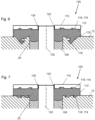
- Figures 5 , 6 and 7 show three further embodiments of the first connection terminal arrangement 100.
- the base body 12 and the electrical feedthrough formed by the connection pin 102 and the fixing material 106 are designed as described with reference to the previous embodiments.
- the part of the connection pin 12 protruding beyond the through-opening 20 in the base body 12 is designed as with reference to the first embodiment of the Figures 1 to 3 electrically connected to the connection pad 110 by a welded connection 130.
- a cast material such as a thermoplastic or thermosetting plastic
- the insulating material 112 is used as the insulating material 112 to connect the connection pad 110 and the base body 12.
- undercuts 119 are provided.
- a recess 118 is arranged in the base body 12, which recess 118 extends around the opening 20 and has an undercut 119 in the form of a circumferential protruding elevation within the recess 118.
- a collar 117 is formed on the connection pad 110 by folding over the edge, which collar represents a circumferential undercut 119.
- a recess 118 is again arranged in the base body 12, which recess 118 extends around the opening 20 and has an undercut 119 in the form of a circumferential protruding elevation within the recess 118.
- Several recesses in the form of oblique grooves are arranged on the connection pad 110, which, due to their design, also form an undercut 119.
- recesses 118 in the form of oblique grooves are formed on both the base body 12 and the connection pad 110, each of which provides an undercut 119 as a support for the insulation material 112.
- connection pad 110 and the base body 12 facing the insulating material 112 can be provided with a microstructure, as shown in the grooves and depressions. This creates many depressions and/or grooves that provide support for the insulating material 112.
- the Figures 8 to 10 show measures for increasing the creepage distance at the edge of a connection pad 110. These are shown here as an example for the second example of a first connection terminal arrangement 100 (cf. Figure 4 ). Of course, they are not limited to connection pad embodiments with an opening 120 designed as a blind hole, but can also be used with other examples of a first connection terminal arrangement, in particular with embodiments according to the Figures 1 to 3 , be combined.
- the outer dimension of the insulating material 112 is selected to be larger than the outer dimension of the connection pad 110, so that part of the insulating material 112 protrudes beyond the connection pad 110.
- a further insulating element 150 can be provided in the edge region of the connection pad 110, which surrounds the connection pad 110 laterally.
- Figure 9 In the second variant shown for extending the creepage distance, the further insulating element 150 is attached, for example glued, to the side next to the connection pad 110 on the protruding insulating material 112.
- Figure 10 shows a third variant for extending the creepage distance in an embodiment in which the insulating material 112 is completely covered by the connection pad 110.
- an insulating creepage distance extension 151 is provided, which covers the gap 152 between the base body 12 and the connection pad 110.
- an "adhesive bead" made of insulating material can be placed around the connection pad 110 in an additional work step.
- the insulating material can be made thicker at least partially below the connection pad 110 and/or an adhesive bead can be additionally provided in the edge region below the connection pad 110, for example, so that when the connection pad 110 is attached to the base body 12, material is pressed out at the edges, thereby forming the creepage distance extension at the gap 152.
Landscapes
- Engineering & Computer Science (AREA)
- Power Engineering (AREA)
- Chemical & Material Sciences (AREA)
- Microelectronics & Electronic Packaging (AREA)
- Chemical Kinetics & Catalysis (AREA)
- Electrochemistry (AREA)
- General Chemical & Material Sciences (AREA)
- Inorganic Chemistry (AREA)
- Manufacturing & Machinery (AREA)
- Connection Of Batteries Or Terminals (AREA)
- Connector Housings Or Holding Contact Members (AREA)
- Electric Double-Layer Capacitors Or The Like (AREA)
- Sealing Battery Cases Or Jackets (AREA)
Applications Claiming Priority (1)
| Application Number | Priority Date | Filing Date | Title |
|---|---|---|---|
| DE102021133391.1A DE102021133391A1 (de) | 2021-12-16 | 2021-12-16 | Gehäuseteil für eine elektrische Speichereinrichtung und elektrische Speichereinrichtung |
Publications (2)
| Publication Number | Publication Date |
|---|---|
| EP4199204A1 EP4199204A1 (de) | 2023-06-21 |
| EP4199204B1 true EP4199204B1 (de) | 2025-04-16 |
Family
ID=84439720
Family Applications (1)
| Application Number | Title | Priority Date | Filing Date |
|---|---|---|---|
| EP22211879.6A Active EP4199204B1 (de) | 2021-12-16 | 2022-12-07 | Gehäuseteil für eine elektrische speichereinrichtung und elektrische speichereinrichtung |
Country Status (6)
| Country | Link |
|---|---|
| US (1) | US20230198111A1 (enExample) |
| EP (1) | EP4199204B1 (enExample) |
| JP (1) | JP2023089969A (enExample) |
| KR (1) | KR20230091800A (enExample) |
| CN (1) | CN116266655A (enExample) |
| DE (1) | DE102021133391A1 (enExample) |
Families Citing this family (4)
| Publication number | Priority date | Publication date | Assignee | Title |
|---|---|---|---|---|
| WO2024247451A1 (ja) | 2023-05-31 | 2024-12-05 | artience株式会社 | 水性インクジェットインキ及び印刷物 |
| DE102023118080A1 (de) | 2023-07-07 | 2025-01-09 | Schott Ag | Elektrische Durchführung und Energiespeicher mit einer solchen Durchführung |
| DE102024123426A1 (de) * | 2024-08-16 | 2026-02-19 | Schaeffler Technologies AG & Co. KG | Verfahren zur Herstellung eines Batteriezellenkontakts und Batteriezelle |
| DE102024124588B3 (de) * | 2024-08-28 | 2025-08-21 | Clarios Advanced Solutions Gmbh | Energiespeichersystem mit mindestens einer energiespeicherzelle zum speichern von elektrischer energie sowie verfahren zum herstellen eines solchen energiespeichersystems |
Family Cites Families (19)
| Publication number | Priority date | Publication date | Assignee | Title |
|---|---|---|---|---|
| US961672A (en) | 1910-01-21 | 1910-06-14 | Henry Gregory Barnhurst | Method of burning powdered fuel. |
| KR100393958B1 (ko) | 1995-07-24 | 2003-11-20 | 스미또모 가가꾸 고교 가부시끼가이샤 | 비수성전해질리튬이차전지 |
| JP3184071B2 (ja) | 1995-09-06 | 2001-07-09 | キヤノン株式会社 | リチウム二次電池 |
| US5773959A (en) | 1996-01-11 | 1998-06-30 | Lockheed Martin Corporation | Lithium polymer battery charger methods and apparatus |
| EP0793286B1 (en) | 1996-01-31 | 1999-03-31 | AEA Technology plc | Grafted polyvinylidene fluoride as a solid polymer electrolyte for eletrochemical cells, and electrochemical cell incorporating same |
| KR100261252B1 (ko) | 1996-07-30 | 2000-07-01 | 윤종용 | 고분자 고체 전해질 및 이를 채용하고 있는 리튬 2차전지 |
| US5874185A (en) | 1997-07-24 | 1999-02-23 | Industrial Technology Research Institute | Polymer electrolyte material for use in lithium and lithium ion batteries |
| JP5684462B2 (ja) * | 2008-12-22 | 2015-03-11 | 昭和電工パッケージング株式会社 | 正極タブリード及び電池 |
| KR101754609B1 (ko) * | 2013-11-20 | 2017-07-06 | 삼성에스디아이 주식회사 | 퓨즈부를 갖는 이차 전지 |
| DE102014016601A1 (de) | 2014-11-11 | 2016-05-12 | Schott Ag | Bauteil mit Bauteilverstärkung und Durchführung |
| KR102467767B1 (ko) * | 2015-11-24 | 2022-11-16 | 삼성에스디아이 주식회사 | 이차 전지 |
| WO2018159180A1 (ja) * | 2017-02-28 | 2018-09-07 | 日立オートモティブシステムズ株式会社 | 二次電池 |
| KR102454791B1 (ko) | 2017-06-13 | 2022-10-14 | 삼성에스디아이 주식회사 | 양극 단자와 멤브레인 일체형 캡 플레이트를 갖는 이차 전지 |
| CN207233790U (zh) * | 2017-08-30 | 2018-04-13 | 宁德时代新能源科技股份有限公司 | 二次电池的顶盖组件以及二次电池 |
| DE102017123278A1 (de) | 2017-10-06 | 2019-04-11 | Schott Ag | Grundkörper mit angelötetem Massestift, Verfahren zu seiner Herstellung und seine Verwendungen |
| JP7085108B2 (ja) * | 2018-02-01 | 2022-06-16 | トヨタ自動車株式会社 | 電池および電池の製造方法 |
| KR102663725B1 (ko) * | 2018-09-19 | 2024-05-07 | 삼성에스디아이 주식회사 | 이차 전지 |
| CN113196430A (zh) | 2018-11-23 | 2021-07-30 | 肖特股份有限公司 | 电气馈通件玻璃金属电极 |
| JP7650425B2 (ja) * | 2022-11-07 | 2025-03-25 | トヨタ自動車株式会社 | 蓄電セル並びに蓋及び外部端子間の短絡方法 |
-
2021
- 2021-12-16 DE DE102021133391.1A patent/DE102021133391A1/de active Pending
-
2022
- 2022-12-07 EP EP22211879.6A patent/EP4199204B1/de active Active
- 2022-12-14 KR KR1020220174771A patent/KR20230091800A/ko active Pending
- 2022-12-15 JP JP2022200014A patent/JP2023089969A/ja active Pending
- 2022-12-16 US US18/083,015 patent/US20230198111A1/en active Pending
- 2022-12-16 CN CN202211626749.8A patent/CN116266655A/zh active Pending
Also Published As
| Publication number | Publication date |
|---|---|
| JP2023089969A (ja) | 2023-06-28 |
| DE102021133391A1 (de) | 2023-06-22 |
| EP4199204A1 (de) | 2023-06-21 |
| US20230198111A1 (en) | 2023-06-22 |
| CN116266655A (zh) | 2023-06-20 |
| KR20230091800A (ko) | 2023-06-23 |
Similar Documents
| Publication | Publication Date | Title |
|---|---|---|
| EP4199204A1 (de) | Gehäuseteil für eine elektrische speichereinrichtung und elektrische speichereinrichtung | |
| EP1483797B1 (de) | Becherförmiges gehäuse und kondensator mit dem gehäuse | |
| DE202020106518U1 (de) | Elektrische Einrichtung | |
| DE102012100862A1 (de) | Zellverbinder | |
| WO2016083144A1 (de) | Gehäuse für den zellstapel einer batterie | |
| WO2019228722A1 (de) | Hybride batteriekomponente und verfahren zum herstellen einer hybriden batteriekomponente | |
| DE102012018041A1 (de) | Isolation von elektrochemischen Energiespeichern | |
| DE102014219001A1 (de) | Batteriezelle mit Zellengehäuse und einer Deckelanordnung mit Batteriekontakten | |
| DE102011103975A1 (de) | Durchführungsbauteil | |
| DE10047206A1 (de) | Gehäuse für elektrochemische Zellen | |
| EP3701575A1 (de) | Batteriezelle und verfahren zum herstellen einer solchen | |
| DE102018220118A1 (de) | Durchführung | |
| WO2025108776A1 (de) | Deckelbaugruppe für eine prismatische zelle | |
| DE202021103495U1 (de) | Elektrische Einrichtung, insbesondere Mikrobatterie | |
| EP4466725A1 (de) | Elektrische durchführung und energiespeicher mit einer solchen durchführung | |
| WO2024046908A1 (de) | Batteriezelle, system, verfahren zur herstellung eines batteriezellverbunds und batteriezellverbund | |
| WO2024132809A1 (de) | Zellgehäuse, elementare elektrische speicherzelle und verfahren zur herstellung | |
| DE102011103976A1 (de) | Durchführung | |
| DE102025120816B3 (de) | Prismatische Batteriezelle sowie Verfahren zur Herstellung einer solchen Batteriezelle | |
| DE102023118080A1 (de) | Elektrische Durchführung und Energiespeicher mit einer solchen Durchführung | |
| EP3839413A1 (de) | Metall-fixiermaterial-durchführung, verfahren zu ihrer herstellung und ihre verwendungen | |
| DE102023113622A1 (de) | Gehäuseteil mit elektrischer Durchführung für eine elektrische Einrichtung und Energiespeicher mit einem solchen Gehäuseteil | |
| DE202023102874U1 (de) | Gehäuseteil mit elektrischer Durchführung für eine elektrische Einrichtung und Energiespeicher mit einem solchen Gehäuseteil | |
| DE102016200511A1 (de) | Isolations- und/oder Dichtungsvorrichtung für eine Energiespeicherzelle, Energiespeicherzelle und Herstellungsverfahren | |
| DE102019213901A1 (de) | Durchführung |
Legal Events
| Date | Code | Title | Description |
|---|---|---|---|
| PUAI | Public reference made under article 153(3) epc to a published international application that has entered the european phase |
Free format text: ORIGINAL CODE: 0009012 |
|
| STAA | Information on the status of an ep patent application or granted ep patent |
Free format text: STATUS: THE APPLICATION HAS BEEN PUBLISHED |
|
| AK | Designated contracting states |
Kind code of ref document: A1 Designated state(s): AL AT BE BG CH CY CZ DE DK EE ES FI FR GB GR HR HU IE IS IT LI LT LU LV MC ME MK MT NL NO PL PT RO RS SE SI SK SM TR |
|
| P01 | Opt-out of the competence of the unified patent court (upc) registered |
Effective date: 20230914 |
|
| STAA | Information on the status of an ep patent application or granted ep patent |
Free format text: STATUS: REQUEST FOR EXAMINATION WAS MADE |
|
| 17P | Request for examination filed |
Effective date: 20231114 |
|
| RBV | Designated contracting states (corrected) |
Designated state(s): AL AT BE BG CH CY CZ DE DK EE ES FI FR GB GR HR HU IE IS IT LI LT LU LV MC ME MK MT NL NO PL PT RO RS SE SI SK SM TR |
|
| STAA | Information on the status of an ep patent application or granted ep patent |
Free format text: STATUS: EXAMINATION IS IN PROGRESS |
|
| 17Q | First examination report despatched |
Effective date: 20240522 |
|
| GRAP | Despatch of communication of intention to grant a patent |
Free format text: ORIGINAL CODE: EPIDOSNIGR1 |
|
| STAA | Information on the status of an ep patent application or granted ep patent |
Free format text: STATUS: GRANT OF PATENT IS INTENDED |
|
| INTG | Intention to grant announced |
Effective date: 20241213 |
|
| GRAS | Grant fee paid |
Free format text: ORIGINAL CODE: EPIDOSNIGR3 |
|
| GRAA | (expected) grant |
Free format text: ORIGINAL CODE: 0009210 |
|
| STAA | Information on the status of an ep patent application or granted ep patent |
Free format text: STATUS: THE PATENT HAS BEEN GRANTED |
|
| AK | Designated contracting states |
Kind code of ref document: B1 Designated state(s): AL AT BE BG CH CY CZ DE DK EE ES FI FR GB GR HR HU IE IS IT LI LT LU LV MC ME MK MT NL NO PL PT RO RS SE SI SK SM TR |
|
| REG | Reference to a national code |
Ref country code: GB Ref legal event code: FG4D Free format text: NOT ENGLISH |
|
| REG | Reference to a national code |
Ref country code: CH Ref legal event code: EP |
|
| REG | Reference to a national code |
Ref country code: IE Ref legal event code: FG4D Free format text: LANGUAGE OF EP DOCUMENT: GERMAN |
|
| REG | Reference to a national code |
Ref country code: DE Ref legal event code: R096 Ref document number: 502022003590 Country of ref document: DE |
|
| REG | Reference to a national code |
Ref country code: SE Ref legal event code: TRGR |
|
| REG | Reference to a national code |
Ref country code: NL Ref legal event code: MP Effective date: 20250416 |
|
| PG25 | Lapsed in a contracting state [announced via postgrant information from national office to epo] |
Ref country code: NL Free format text: LAPSE BECAUSE OF FAILURE TO SUBMIT A TRANSLATION OF THE DESCRIPTION OR TO PAY THE FEE WITHIN THE PRESCRIBED TIME-LIMIT Effective date: 20250416 |
|
| PG25 | Lapsed in a contracting state [announced via postgrant information from national office to epo] |
Ref country code: FI Free format text: LAPSE BECAUSE OF FAILURE TO SUBMIT A TRANSLATION OF THE DESCRIPTION OR TO PAY THE FEE WITHIN THE PRESCRIBED TIME-LIMIT Effective date: 20250416 Ref country code: ES Free format text: LAPSE BECAUSE OF FAILURE TO SUBMIT A TRANSLATION OF THE DESCRIPTION OR TO PAY THE FEE WITHIN THE PRESCRIBED TIME-LIMIT Effective date: 20250416 Ref country code: PT Free format text: LAPSE BECAUSE OF FAILURE TO SUBMIT A TRANSLATION OF THE DESCRIPTION OR TO PAY THE FEE WITHIN THE PRESCRIBED TIME-LIMIT Effective date: 20250818 |
|
| REG | Reference to a national code |
Ref country code: LT Ref legal event code: MG9D |
|
| PG25 | Lapsed in a contracting state [announced via postgrant information from national office to epo] |
Ref country code: GR Free format text: LAPSE BECAUSE OF FAILURE TO SUBMIT A TRANSLATION OF THE DESCRIPTION OR TO PAY THE FEE WITHIN THE PRESCRIBED TIME-LIMIT Effective date: 20250717 |
|
| PG25 | Lapsed in a contracting state [announced via postgrant information from national office to epo] |
Ref country code: PL Free format text: LAPSE BECAUSE OF FAILURE TO SUBMIT A TRANSLATION OF THE DESCRIPTION OR TO PAY THE FEE WITHIN THE PRESCRIBED TIME-LIMIT Effective date: 20250416 |
|
| PG25 | Lapsed in a contracting state [announced via postgrant information from national office to epo] |
Ref country code: BG Free format text: LAPSE BECAUSE OF FAILURE TO SUBMIT A TRANSLATION OF THE DESCRIPTION OR TO PAY THE FEE WITHIN THE PRESCRIBED TIME-LIMIT Effective date: 20250416 |
|
| PG25 | Lapsed in a contracting state [announced via postgrant information from national office to epo] |
Ref country code: HR Free format text: LAPSE BECAUSE OF FAILURE TO SUBMIT A TRANSLATION OF THE DESCRIPTION OR TO PAY THE FEE WITHIN THE PRESCRIBED TIME-LIMIT Effective date: 20250416 |
|
| PG25 | Lapsed in a contracting state [announced via postgrant information from national office to epo] |
Ref country code: RS Free format text: LAPSE BECAUSE OF FAILURE TO SUBMIT A TRANSLATION OF THE DESCRIPTION OR TO PAY THE FEE WITHIN THE PRESCRIBED TIME-LIMIT Effective date: 20250716 |
|
| PG25 | Lapsed in a contracting state [announced via postgrant information from national office to epo] |
Ref country code: IS Free format text: LAPSE BECAUSE OF FAILURE TO SUBMIT A TRANSLATION OF THE DESCRIPTION OR TO PAY THE FEE WITHIN THE PRESCRIBED TIME-LIMIT Effective date: 20250816 |
|
| PG25 | Lapsed in a contracting state [announced via postgrant information from national office to epo] |
Ref country code: LV Free format text: LAPSE BECAUSE OF FAILURE TO SUBMIT A TRANSLATION OF THE DESCRIPTION OR TO PAY THE FEE WITHIN THE PRESCRIBED TIME-LIMIT Effective date: 20250416 |
|
| PGFP | Annual fee paid to national office [announced via postgrant information from national office to epo] |
Ref country code: DE Payment date: 20251211 Year of fee payment: 4 |
|
| PG25 | Lapsed in a contracting state [announced via postgrant information from national office to epo] |
Ref country code: SM Free format text: LAPSE BECAUSE OF FAILURE TO SUBMIT A TRANSLATION OF THE DESCRIPTION OR TO PAY THE FEE WITHIN THE PRESCRIBED TIME-LIMIT Effective date: 20250416 Ref country code: DK Free format text: LAPSE BECAUSE OF FAILURE TO SUBMIT A TRANSLATION OF THE DESCRIPTION OR TO PAY THE FEE WITHIN THE PRESCRIBED TIME-LIMIT Effective date: 20250416 |
|
| PGFP | Annual fee paid to national office [announced via postgrant information from national office to epo] |
Ref country code: AT Payment date: 20260113 Year of fee payment: 4 |
|
| PGFP | Annual fee paid to national office [announced via postgrant information from national office to epo] |
Ref country code: SE Payment date: 20251219 Year of fee payment: 4 |
|
| REG | Reference to a national code |
Ref country code: DE Ref legal event code: R097 Ref document number: 502022003590 Country of ref document: DE |
|
| PG25 | Lapsed in a contracting state [announced via postgrant information from national office to epo] |
Ref country code: CZ Free format text: LAPSE BECAUSE OF FAILURE TO SUBMIT A TRANSLATION OF THE DESCRIPTION OR TO PAY THE FEE WITHIN THE PRESCRIBED TIME-LIMIT Effective date: 20250416 |
|
| PG25 | Lapsed in a contracting state [announced via postgrant information from national office to epo] |
Ref country code: EE Free format text: LAPSE BECAUSE OF FAILURE TO SUBMIT A TRANSLATION OF THE DESCRIPTION OR TO PAY THE FEE WITHIN THE PRESCRIBED TIME-LIMIT Effective date: 20250416 |
|
| PG25 | Lapsed in a contracting state [announced via postgrant information from national office to epo] |
Ref country code: SK Free format text: LAPSE BECAUSE OF FAILURE TO SUBMIT A TRANSLATION OF THE DESCRIPTION OR TO PAY THE FEE WITHIN THE PRESCRIBED TIME-LIMIT Effective date: 20250416 |
|
| PG25 | Lapsed in a contracting state [announced via postgrant information from national office to epo] |
Ref country code: IT Free format text: LAPSE BECAUSE OF FAILURE TO SUBMIT A TRANSLATION OF THE DESCRIPTION OR TO PAY THE FEE WITHIN THE PRESCRIBED TIME-LIMIT Effective date: 20250416 |
|
| PLBE | No opposition filed within time limit |
Free format text: ORIGINAL CODE: 0009261 |
|
| STAA | Information on the status of an ep patent application or granted ep patent |
Free format text: STATUS: NO OPPOSITION FILED WITHIN TIME LIMIT |
|
| REG | Reference to a national code |
Ref country code: CH Ref legal event code: L10 Free format text: ST27 STATUS EVENT CODE: U-0-0-L10-L00 (AS PROVIDED BY THE NATIONAL OFFICE) Effective date: 20260225 |
|
| PG25 | Lapsed in a contracting state [announced via postgrant information from national office to epo] |
Ref country code: RO Free format text: LAPSE BECAUSE OF FAILURE TO SUBMIT A TRANSLATION OF THE DESCRIPTION OR TO PAY THE FEE WITHIN THE PRESCRIBED TIME-LIMIT Effective date: 20250416 |
|
| 26N | No opposition filed |
Effective date: 20260119 |
|
| PGFP | Annual fee paid to national office [announced via postgrant information from national office to epo] |
Ref country code: NO Payment date: 20251230 Year of fee payment: 4 |