EP4199149B1 - Wiederaufladbare batteriezelle - Google Patents
Wiederaufladbare batteriezelle Download PDFInfo
- Publication number
- EP4199149B1 EP4199149B1 EP21215533.7A EP21215533A EP4199149B1 EP 4199149 B1 EP4199149 B1 EP 4199149B1 EP 21215533 A EP21215533 A EP 21215533A EP 4199149 B1 EP4199149 B1 EP 4199149B1
- Authority
- EP
- European Patent Office
- Prior art keywords
- battery cell
- rechargeable battery
- sodium
- electrolyte
- group
- Prior art date
- Legal status (The legal status is an assumption and is not a legal conclusion. Google has not performed a legal analysis and makes no representation as to the accuracy of the status listed.)
- Active
Links
Images
Classifications
-
- H—ELECTRICITY
- H01—ELECTRIC ELEMENTS
- H01M—PROCESSES OR MEANS, e.g. BATTERIES, FOR THE DIRECT CONVERSION OF CHEMICAL ENERGY INTO ELECTRICAL ENERGY
- H01M10/00—Secondary cells; Manufacture thereof
- H01M10/05—Accumulators with non-aqueous electrolyte
- H01M10/056—Accumulators with non-aqueous electrolyte characterised by the materials used as electrolytes, e.g. mixed inorganic/organic electrolytes
- H01M10/0564—Accumulators with non-aqueous electrolyte characterised by the materials used as electrolytes, e.g. mixed inorganic/organic electrolytes the electrolyte being constituted of organic materials only
- H01M10/0566—Liquid materials
- H01M10/0567—Liquid materials characterised by the additives
-
- H—ELECTRICITY
- H01—ELECTRIC ELEMENTS
- H01M—PROCESSES OR MEANS, e.g. BATTERIES, FOR THE DIRECT CONVERSION OF CHEMICAL ENERGY INTO ELECTRICAL ENERGY
- H01M4/00—Electrodes
- H01M4/02—Electrodes composed of, or comprising, active material
- H01M4/36—Selection of substances as active materials, active masses, active liquids
- H01M4/38—Selection of substances as active materials, active masses, active liquids of elements or alloys
- H01M4/381—Alkaline or alkaline earth metals elements
-
- H—ELECTRICITY
- H01—ELECTRIC ELEMENTS
- H01M—PROCESSES OR MEANS, e.g. BATTERIES, FOR THE DIRECT CONVERSION OF CHEMICAL ENERGY INTO ELECTRICAL ENERGY
- H01M4/00—Electrodes
- H01M4/02—Electrodes composed of, or comprising, active material
- H01M4/36—Selection of substances as active materials, active masses, active liquids
- H01M4/38—Selection of substances as active materials, active masses, active liquids of elements or alloys
-
- H—ELECTRICITY
- H01—ELECTRIC ELEMENTS
- H01M—PROCESSES OR MEANS, e.g. BATTERIES, FOR THE DIRECT CONVERSION OF CHEMICAL ENERGY INTO ELECTRICAL ENERGY
- H01M10/00—Secondary cells; Manufacture thereof
- H01M10/05—Accumulators with non-aqueous electrolyte
- H01M10/054—Accumulators with insertion or intercalation of metals other than lithium, e.g. with magnesium or aluminium
-
- H—ELECTRICITY
- H01—ELECTRIC ELEMENTS
- H01M—PROCESSES OR MEANS, e.g. BATTERIES, FOR THE DIRECT CONVERSION OF CHEMICAL ENERGY INTO ELECTRICAL ENERGY
- H01M10/00—Secondary cells; Manufacture thereof
- H01M10/05—Accumulators with non-aqueous electrolyte
- H01M10/056—Accumulators with non-aqueous electrolyte characterised by the materials used as electrolytes, e.g. mixed inorganic/organic electrolytes
- H01M10/0561—Accumulators with non-aqueous electrolyte characterised by the materials used as electrolytes, e.g. mixed inorganic/organic electrolytes the electrolyte being constituted of inorganic materials only
- H01M10/0563—Liquid materials, e.g. for Li-SOCl2 cells
-
- H—ELECTRICITY
- H01—ELECTRIC ELEMENTS
- H01M—PROCESSES OR MEANS, e.g. BATTERIES, FOR THE DIRECT CONVERSION OF CHEMICAL ENERGY INTO ELECTRICAL ENERGY
- H01M10/00—Secondary cells; Manufacture thereof
- H01M10/05—Accumulators with non-aqueous electrolyte
- H01M10/056—Accumulators with non-aqueous electrolyte characterised by the materials used as electrolytes, e.g. mixed inorganic/organic electrolytes
- H01M10/0564—Accumulators with non-aqueous electrolyte characterised by the materials used as electrolytes, e.g. mixed inorganic/organic electrolytes the electrolyte being constituted of organic materials only
- H01M10/0566—Liquid materials
- H01M10/0568—Liquid materials characterised by the solutes
-
- H—ELECTRICITY
- H01—ELECTRIC ELEMENTS
- H01M—PROCESSES OR MEANS, e.g. BATTERIES, FOR THE DIRECT CONVERSION OF CHEMICAL ENERGY INTO ELECTRICAL ENERGY
- H01M4/00—Electrodes
- H01M4/02—Electrodes composed of, or comprising, active material
- H01M4/36—Selection of substances as active materials, active masses, active liquids
- H01M4/58—Selection of substances as active materials, active masses, active liquids of inorganic compounds other than oxides or hydroxides, e.g. sulfides, selenides, tellurides, halogenides or LiCoFy; of polyanionic structures, e.g. phosphates, silicates or borates
- H01M4/583—Carbonaceous material, e.g. graphite-intercalation compounds or CFx
-
- H—ELECTRICITY
- H01—ELECTRIC ELEMENTS
- H01M—PROCESSES OR MEANS, e.g. BATTERIES, FOR THE DIRECT CONVERSION OF CHEMICAL ENERGY INTO ELECTRICAL ENERGY
- H01M4/00—Electrodes
- H01M4/02—Electrodes composed of, or comprising, active material
- H01M4/62—Selection of inactive substances as ingredients for active masses, e.g. binders, fillers
- H01M4/624—Electric conductive fillers
- H01M4/626—Metals
-
- H—ELECTRICITY
- H01—ELECTRIC ELEMENTS
- H01M—PROCESSES OR MEANS, e.g. BATTERIES, FOR THE DIRECT CONVERSION OF CHEMICAL ENERGY INTO ELECTRICAL ENERGY
- H01M4/00—Electrodes
- H01M4/02—Electrodes composed of, or comprising, active material
- H01M4/64—Carriers or collectors
- H01M4/66—Selection of materials
- H01M4/661—Metal or alloys, e.g. alloy coatings
- H01M4/662—Alloys
-
- H—ELECTRICITY
- H01—ELECTRIC ELEMENTS
- H01M—PROCESSES OR MEANS, e.g. BATTERIES, FOR THE DIRECT CONVERSION OF CHEMICAL ENERGY INTO ELECTRICAL ENERGY
- H01M4/00—Electrodes
- H01M4/02—Electrodes composed of, or comprising, active material
- H01M4/64—Carriers or collectors
- H01M4/66—Selection of materials
- H01M4/665—Composites
-
- H—ELECTRICITY
- H01—ELECTRIC ELEMENTS
- H01M—PROCESSES OR MEANS, e.g. BATTERIES, FOR THE DIRECT CONVERSION OF CHEMICAL ENERGY INTO ELECTRICAL ENERGY
- H01M4/00—Electrodes
- H01M4/02—Electrodes composed of, or comprising, active material
- H01M2004/026—Electrodes composed of, or comprising, active material characterised by the polarity
- H01M2004/027—Negative electrodes
-
- H—ELECTRICITY
- H01—ELECTRIC ELEMENTS
- H01M—PROCESSES OR MEANS, e.g. BATTERIES, FOR THE DIRECT CONVERSION OF CHEMICAL ENERGY INTO ELECTRICAL ENERGY
- H01M4/00—Electrodes
- H01M4/02—Electrodes composed of, or comprising, active material
- H01M2004/026—Electrodes composed of, or comprising, active material characterised by the polarity
- H01M2004/028—Positive electrodes
-
- H—ELECTRICITY
- H01—ELECTRIC ELEMENTS
- H01M—PROCESSES OR MEANS, e.g. BATTERIES, FOR THE DIRECT CONVERSION OF CHEMICAL ENERGY INTO ELECTRICAL ENERGY
- H01M2300/00—Electrolytes
- H01M2300/0017—Non-aqueous electrolytes
- H01M2300/002—Inorganic electrolyte
-
- H—ELECTRICITY
- H01—ELECTRIC ELEMENTS
- H01M—PROCESSES OR MEANS, e.g. BATTERIES, FOR THE DIRECT CONVERSION OF CHEMICAL ENERGY INTO ELECTRICAL ENERGY
- H01M4/00—Electrodes
- H01M4/02—Electrodes composed of, or comprising, active material
- H01M4/36—Selection of substances as active materials, active masses, active liquids
- H01M4/48—Selection of substances as active materials, active masses, active liquids of inorganic oxides or hydroxides
- H01M4/483—Selection of substances as active materials, active masses, active liquids of inorganic oxides or hydroxides for non-aqueous cells
-
- H—ELECTRICITY
- H01—ELECTRIC ELEMENTS
- H01M—PROCESSES OR MEANS, e.g. BATTERIES, FOR THE DIRECT CONVERSION OF CHEMICAL ENERGY INTO ELECTRICAL ENERGY
- H01M4/00—Electrodes
- H01M4/02—Electrodes composed of, or comprising, active material
- H01M4/36—Selection of substances as active materials, active masses, active liquids
- H01M4/48—Selection of substances as active materials, active masses, active liquids of inorganic oxides or hydroxides
- H01M4/485—Selection of substances as active materials, active masses, active liquids of inorganic oxides or hydroxides of mixed oxides or hydroxides for inserting or intercalating light metals, e.g. LiTi2O4 or LiTi2OxFy
-
- H—ELECTRICITY
- H01—ELECTRIC ELEMENTS
- H01M—PROCESSES OR MEANS, e.g. BATTERIES, FOR THE DIRECT CONVERSION OF CHEMICAL ENERGY INTO ELECTRICAL ENERGY
- H01M4/00—Electrodes
- H01M4/02—Electrodes composed of, or comprising, active material
- H01M4/36—Selection of substances as active materials, active masses, active liquids
- H01M4/48—Selection of substances as active materials, active masses, active liquids of inorganic oxides or hydroxides
- H01M4/52—Selection of substances as active materials, active masses, active liquids of inorganic oxides or hydroxides of nickel, cobalt or iron
- H01M4/525—Selection of substances as active materials, active masses, active liquids of inorganic oxides or hydroxides of nickel, cobalt or iron of mixed oxides or hydroxides containing iron, cobalt or nickel for inserting or intercalating light metals, e.g. LiNiO2, LiCoO2 or LiCoOxFy
-
- H—ELECTRICITY
- H01—ELECTRIC ELEMENTS
- H01M—PROCESSES OR MEANS, e.g. BATTERIES, FOR THE DIRECT CONVERSION OF CHEMICAL ENERGY INTO ELECTRICAL ENERGY
- H01M4/00—Electrodes
- H01M4/02—Electrodes composed of, or comprising, active material
- H01M4/36—Selection of substances as active materials, active masses, active liquids
- H01M4/58—Selection of substances as active materials, active masses, active liquids of inorganic compounds other than oxides or hydroxides, e.g. sulfides, selenides, tellurides, halogenides or LiCoFy; of polyanionic structures, e.g. phosphates, silicates or borates
- H01M4/581—Chalcogenides or intercalation compounds thereof
- H01M4/5815—Sulfides
-
- H—ELECTRICITY
- H01—ELECTRIC ELEMENTS
- H01M—PROCESSES OR MEANS, e.g. BATTERIES, FOR THE DIRECT CONVERSION OF CHEMICAL ENERGY INTO ELECTRICAL ENERGY
- H01M4/00—Electrodes
- H01M4/02—Electrodes composed of, or comprising, active material
- H01M4/36—Selection of substances as active materials, active masses, active liquids
- H01M4/58—Selection of substances as active materials, active masses, active liquids of inorganic compounds other than oxides or hydroxides, e.g. sulfides, selenides, tellurides, halogenides or LiCoFy; of polyanionic structures, e.g. phosphates, silicates or borates
- H01M4/583—Carbonaceous material, e.g. graphite-intercalation compounds or CFx
- H01M4/587—Carbonaceous material, e.g. graphite-intercalation compounds or CFx for inserting or intercalating light metals
-
- H—ELECTRICITY
- H01—ELECTRIC ELEMENTS
- H01M—PROCESSES OR MEANS, e.g. BATTERIES, FOR THE DIRECT CONVERSION OF CHEMICAL ENERGY INTO ELECTRICAL ENERGY
- H01M4/00—Electrodes
- H01M4/02—Electrodes composed of, or comprising, active material
- H01M4/64—Carriers or collectors
- H01M4/66—Selection of materials
- H01M4/661—Metal or alloys, e.g. alloy coatings
-
- Y—GENERAL TAGGING OF NEW TECHNOLOGICAL DEVELOPMENTS; GENERAL TAGGING OF CROSS-SECTIONAL TECHNOLOGIES SPANNING OVER SEVERAL SECTIONS OF THE IPC; TECHNICAL SUBJECTS COVERED BY FORMER USPC CROSS-REFERENCE ART COLLECTIONS [XRACs] AND DIGESTS
- Y02—TECHNOLOGIES OR APPLICATIONS FOR MITIGATION OR ADAPTATION AGAINST CLIMATE CHANGE
- Y02E—REDUCTION OF GREENHOUSE GAS [GHG] EMISSIONS, RELATED TO ENERGY GENERATION, TRANSMISSION OR DISTRIBUTION
- Y02E60/00—Enabling technologies; Technologies with a potential or indirect contribution to GHG emissions mitigation
- Y02E60/10—Energy storage using batteries
Definitions
- the invention relates to a rechargeable battery cell comprising sodium as active metal.
- Rechargeable battery cells are of great importance in many technical fields. They are often used for applications where only small rechargeable battery cells with relatively low currents are required, such as for operating mobile phones. However, there is also a great need for larger rechargeable battery cells for high-energy applications, whereby mass storage of energy in the form of battery cells is of particular importance for the electric drive of vehicles.
- the active metal of a rechargeable battery cell is the metal whose ions migrate to the negative or positive electrode within the electrolyte when the cell is charged or discharged and participate in electrochemical processes there. These electrochemical processes lead directly or indirectly to the release of electrons into the external circuit or to the absorption of electrons from the external circuit.
- Active metals can be lithium or sodium, as mentioned above.
- Rechargeable battery cells that contain lithium or sodium as the active metal are also called lithium-ion cells or sodium-ion cells.
- Lithium-ion cells have been known for a long time and are described in detail in the state of the art.
- sodium-ion cells have only been the focus of research since 2010 and are described in more detail below. Most research activities have been devoted to the discovery of high-performance anodes to increase the energy density of sodium-ion batteries, since graphite, the main material used in lithium-ion cells, has a much lower storage capacity for sodium compared to lithium.
- the sodium ion cell has a housing in which at least one positive electrode with a discharge element, at least one negative electrode with a discharge element and an electrolyte are arranged.
- Both the positive and the negative electrode of the sodium ion cells known from the prior art are designed as insertion electrodes.
- the term "insertion electrode” in the sense of the present invention refers to electrodes which have a crystal structure into which ions of the active metal can be inserted and removed during operation of the sodium ion cell. This means that the electrode processes can take place not only on the surface of the electrodes, but also within the crystal structure.
- the electrolyte is also an important functional element of every rechargeable battery cell. It usually contains a solvent or solvent mixture and at least one conducting salt. Solid electrolytes or ionic liquids, for example, do not contain a solvent, but only a conducting salt.
- the electrolyte is in contact with the positive and negative electrodes of the battery cell. At least one ion of the conducting salt (anion or cation) is so mobile in the electrolyte that the charge transport required for the function of the rechargeable battery cell can take place between the electrodes through ion conduction.
- the electrolyte is oxidatively electrochemically decomposed above a certain upper cell voltage of the rechargeable battery cell.
- Reductive processes can also decompose the electrolyte above a certain lower cell voltage.
- the positive and negative electrodes are selected such that the cell voltage is below or above the decomposition voltage of the electrolyte. The electrolyte thus determines the voltage window within which a rechargeable battery cell can be operated reversibly, i.e. repeatedly charged and discharged.
- the organic sodium ion cells known from the prior art contain an electrolyte consisting of an organic solvent or solvent mixture and a conducting salt dissolved therein.
- the conducting salt is a sodium salt such as sodium perchlorate (NaClO 4 ) or sodium hexafluorophosphate (NaPF 6 ).
- the organic solvent mixture can be, for example, propylene carbonate (PC).
- Solvent mixtures can be ethylene carbonate (EC), diethyl carbonate (DEC) or dimethyl carbonate (DMC). For example, the following mixtures are used: EC:DEC, EC:PC or EC:DMC.
- organic sodium ion cells Due to the use of the organic solvent or solvent mixture, such sodium ion cells are also called organic sodium ion cells.
- a suitable negative electrode for organic sodium ion cells consists, for example, of carbon in the hard carbon modification.
- Hard carbon has a capacity of 300 mAh/g and a cycle efficiency in the first cycle of 80%.
- Positive electrodes of the organic sodium ion cell can consist of layered oxides such as NaMeO x or polyanionic compounds such as phosphates (NaMePO 4 ), pyrophosphates (Na 2 MeP 2 O 7 ) and fluorophosphates (Na 2 Me(PO) 4 F), where "Me” stands for a transition metal.
- Sodium is a very electronegative metal (-2.71 V vs. standard hydrogen electrode, SHE), which creates a very high cell voltage against a positive electrode.
- SHE standard hydrogen electrode
- the reduction of the organic electrolyte takes place.
- This reductive decomposition is irreversible.
- No organic solvents are thermodynamically stable towards sodium or towards sodium stored in carbon.
- many solvents form a passivation film on the electrode surface of the negative electrode. This film spatially separates the solvent from the electrode, but is ionically conductive, allowing the passage of sodium ions.
- the passivation film called the " S olid E lectrolyte I nterphase" (SEI) provides stability to the system, enabling the production of organic sodium-ion cells.
- SEI S olid E lectrolyte I nterphase
- organic sodium-ion cells If an organic sodium-ion cell catches fire or even explodes, the organic solvent of the electrolyte forms a flammable material.
- Another disadvantage of organic sodium-ion cells is the decomposition of the organic components of the SEI layer and the associated associated release of toxic gases. This also causes the cell to heat up further.
- additional measures must be taken. These measures include, in particular, very precise control of the charging and discharging processes of the organic sodium-ion cell.
- the additional measures are considered to be disadvantageous in the event of a possible marketing.
- a further development known from the state of the art provides for the use of an electrolyte based on sulfur dioxide (SO 2 ) instead of an organic electrolyte for rechargeable battery cells.
- Rechargeable battery cells which contain an electrolyte based on SO 2 have, among other things, a high ionic conductivity.
- SO 2 -based electrolyte refers to an electrolyte which not only contains SO 2 as an additive in a low concentration, but in which the mobility of the ions of the conductive salt contained in the electrolyte and which causes the charge transport is at least partially, largely or even completely ensured by SO 2.
- the SO 2 therefore serves as a solvent for the conductive salt.
- the conductive salt can form a liquid solvate complex with the gaseous SO 2 , whereby the SO 2 is bound and the vapor pressure is noticeably reduced compared to pure SO 2. Electrolytes with a low vapor pressure are created. Compared to the organic electrolytes described above, such SO 2 -based electrolytes have the advantage of being non-flammable. Safety risks that arise due to the flammability of the electrolyte can thus be excluded.
- the EP 3 772 129 A1 (referred to as [V4]) a new group of conducting salts for SO 2 -based electrolytes.
- These conducting salts consist of an anion with four substituted hydroxy groups grouped around the central atom boron or aluminum and a cation consisting of the active metal of the cell. All examples show experiments exclusively with lithium salts of this type.
- EP 3 794 666 A1 also discloses a rechargeable battery cell comprising an SO 2 -based electrolyte and an aluminate or borate salt as the first conductive salt. Lithium is used exclusively as the active metal.
- a problem with SO 2 -based electrolytes is that many conductive salts, especially those known for organic sodium ion cells, are not soluble in SO 2 and thus such conductive salts are unsuitable for use in rechargeable sodium ion cells with an SO 2 -based electrolyte.
- Such rechargeable battery cells should in particular also have very good electrical energy and performance data, high operational reliability and service life, in particular a high number of usable charging and discharging cycles, without the electrolyte decomposing during operation of the rechargeable battery cell.
- the formulation "chelate ligand which is formed jointly by at least two of the substituents R 1 , R 2 , R 3 and R 4 and is coordinated to Z" is to be understood in the sense of the present invention that at least two of the substituents R 1 , R 2 , R 3 and R 4 can be bridged to one another, this bridging of two substituents leading to the formation of a bidentate chelate ligand.
- the chelate ligand can be bidentate according to the formula -OR 5 -O-.
- the first substituent R 1 can preferably be an OR 5 group and the second substituent R 2 can preferably be a hydroxy group, which in their bridged state are connected to one another by forming a chemical bond. and therefore have the aforementioned formula -OR 5 -O-.
- Such chelate ligands can, for example, have the following structural formulas:
- the chelate ligand coordinates to the central atom Z to form a chelate complex.
- the two oxygen atoms coordinate to the central atom Z.
- Such chelate complexes can be prepared synthetically as in Example 1 described below.
- the term "chelate complex” refers to complex compounds in which a multidentate ligand (has more than one free electron pair) occupies at least two coordination sites (binding sites) of the central atom.
- the chelate ligand can also be multidentate if three or four of the substituents R 1 , R 2 , R 3 and R 4 are each bridged to one another.
- the SO 2 -based electrolyte used in the rechargeable battery cell according to the invention contains SO 2 not only as an additive in a low concentration, but in concentrations at which the mobility of the ions of the first conducting salt, which is contained in the electrolyte and effects the charge transport, is at least partially, largely or even completely ensured by the SO 2.
- the first conducting salt is dissolved in the electrolyte and shows very good solubility therein. It can form a liquid solvate complex with the gaseous SO 2 in which the SO 2 is bound. In this case, the vapor pressure of the liquid solvate complex drops significantly compared to pure SO 2 and electrolytes with a low vapor pressure are formed.
- the electrolyte can also contain several conductive salts of formula (I) which differ from one another in their chemical structure.
- the term "C 1 -C 10 alkyl" in the sense of the present invention includes linear or branched saturated hydrocarbon groups with one to ten carbon atoms.
- n-propyl examples include in particular methyl, ethyl, n-propyl, isopropyl, n-butyl, sec-butyl, iso-butyl, tert-butyl, n-pentyl, iso-pentyl, 2,2-dimethylpropyl, n-hexyl, iso-hexyl, 2-ethylhexyl, n-heptyl, iso-heptyl, n-octyl, iso-octyl, n-nonyl, n-decyl and the like.
- C 2 -C 10 alkenyl in the sense of the present invention includes unsaturated linear or branched hydrocarbon groups having two to ten carbon atoms, where the hydrocarbon groups have at least one CC double bond. These include in particular ethenyl, 1-propenyl, 2-propenyl, 1-n-butenyl, 2-n-butenyl, isobutenyl, 1-pentenyl, 1-hexenyl, 1-heptenyl, 1-octenyl, 1-nonenyl, 1-decenyl and the like.
- C 2 -C 10 alkynyl in the sense of the present invention includes unsaturated linear or branched hydrocarbon groups having two to ten carbon atoms, where the hydrocarbon groups have at least one CC triple bond.
- these include in particular ethynyl, 1-propynyl, 2-propynyl, 1-n-butynyl, 2-n-butynyl, isobutynyl, 1-pentynyl, 1-hexynyl, 1-heptynyl, 1-octynyl, 1-nonynyl, 1-decynyl and the like.
- C 3 -C 10 cycloalkyl in the sense of the present invention includes cyclic, saturated hydrocarbon groups having three to ten carbon atoms. These include in particular cyclopropyl, cyclobutyl, cyclopentyl, cyclohexyl, cycloheptyl, cyclohexyl, cyclononyl and cyclodecanyl.
- C 6 -C 14 aryl in the sense of the present invention includes aromatic hydrocarbon groups with six to fourteen ring carbon atoms. These include in particular phenyl (C 6 H 5 group), naphthyl (C 10 H 7 group) and anthracyl (C 14 H 9 group).
- C 5 - C 14 heteroaryl in the sense of the present invention includes aromatic hydrocarbon groups with five to fourteen ring-positioned hydrocarbon atoms in which at least one hydrocarbon atom is replaced or exchanged by a nitrogen, oxygen or sulfur atom.
- aromatic hydrocarbon groups with five to fourteen ring-positioned hydrocarbon atoms in which at least one hydrocarbon atom is replaced or exchanged by a nitrogen, oxygen or sulfur atom.
- hydrocarbon groups include in particular pyrrolyl, furanyl, thiophenyl, pyrridinyl, pyranyl, thiopyranyl and the like. All of the aforementioned hydrocarbon groups are each bonded to the central atom according to formula (I) via the oxygen atom.
- the aliphatic, cyclic, aromatic and heteroaromatic radicals/groups can be unsubstituted or substituted.
- substitution one or more hydrogen atoms of the aliphatic, cyclic, aromatic and heteroaromatic radicals/groups are replaced by an atom, such as fluorine or chlorine, or a chemical group, such as CF 3 .
- the rechargeable battery cell according to the invention uses inexpensive and readily available sodium as the active metal and thus has the first major advantage over the lithium-ion cells known from the prior art.
- the rechargeable battery cell according to the invention with such an electrolyte has the advantage over rechargeable battery cells with SO 2 -based electrolytes with sodium conducting salts known from the prior art that the first conducting salt of the formula (I) contained therein has a higher oxidation stability and consequently shows essentially no decomposition at higher cell voltages.
- This electrolyte is oxidation-stable preferably at least up to an upper potential of 3.6 volts, more preferably at least up to an upper potential of 3.8 volts, more preferably at least up to an upper potential of 4.0 volts, more preferably at least up to an upper potential of 4.2 volts, more preferably at least up to an upper potential of 4.4 volts and particularly preferably at least up to an upper potential of 4.6 volts.
- the service life of the rechargeable battery cell according to the invention is significantly extended compared to rechargeable battery cells that contain electrolytes known from the prior art.
- the rechargeable battery cell according to the invention with such an electrolyte is also resistant to low temperatures.
- the conductivity of the electrolyte at low temperatures is sufficient to operate a battery cell.
- the rechargeable battery cell according to the invention comprising the electrolyte outweigh the disadvantage that arises from the fact that the first conducting salt of formula (I) has a significantly larger anion size compared to the sodium conducting salts known from the prior art. This larger anion size leads to a lower conductivity of the first conducting salt according to formula (I) compared to the conductivity of NaAlCl 4 .
- an advantageous development of the rechargeable battery cell according to the invention provides that the active material of the negative electrode consists of metallic sodium and/or at least one sodium-storing material selected from the group consisting of insertion materials, adsorption materials, alloy-forming materials and conversion materials.
- the active material of the negative electrode is metallic sodium.
- the negative electrode also comprises a discharge element. This discharge element serves to enable the required electronically conductive connection of the active material of the negative electrode.
- the discharge element is in contact with the active material involved in the electrode reaction of the negative electrode.
- a further advantageous development of the rechargeable battery cell according to the invention with metallic sodium as the active material of the negative electrode provides that the electronically conductive discharge element of the negative electrode already comprises metallic sodium before the first charging of the rechargeable battery cell, which was applied to the discharge element before the battery cell was assembled and built into the battery cell together with it, or which was deposited on the discharge element of the negative electrode by a preceding initialization charging process before the battery cell was operated, i.e. before the first charging and discharging.
- a further advantageous development of the battery cell according to the invention with metallic sodium as the active material of the negative electrode provides that the discharge element of the negative electrode is at least partially made of a sodium-storing material.
- the active material of the negative electrode consists of at least a sodium-storing material selected from the group consisting of insertion materials, adsorption materials, alloy-forming materials and conversion materials.
- the term “insertion materials” refers to materials in which the ions of the active metal are stored during charging of the rechargeable battery cell and from which the ions of the active metal can be removed during discharging of the rechargeable battery cell. This means that the electrode processes can take place not only on the surface of the negative electrode, but also inside the negative electrode.
- the term “adsorption materials” refers to materials which, in contrast to insertion materials, which have a structure into which the ions of the active metal can be stored and removed during operation of the sodium ion cell, in the case of adsorption materials the ions are deposited on the surface. In many materials, insertion and adsorption also take place simultaneously.
- alloy-forming materials refers to materials which are generally metals and metal alloys as well as their oxides which form an alloy with the active metal, such as sodium, whereby this alloy formation takes place in or on the negative electrode and is essentially reversible.
- the active metal in the alloys is not incorporated into an already existing structure. Rather, the active metal is incorporated via phase transformation processes which, for example, when sodium is used as the active metal, can lead to a sodium-containing, binary end product. During alloy formation, the active material can expand.
- conversion materials refers to materials which undergo a chemical conversion or transformation during the electrode processes, which leads to the reversible formation of a chemical bond between the active metal and the active material.
- the sodium-storing material can preferably be the insertion material containing carbon.
- insertion materials made of carbon in the sense of the present invention refers to materials made of the element carbon that fall under the term "insertion materials” defined above.
- the insertion material containing carbon is selected from the group consisting of hard carbon, soft carbon, graphene or heteroatom-doped carbons. Hard carbon can be synthesized from the carbonization of a variety of precursors such as biomass, lignin, cellulose and many types of polymers.
- Carbonaceous materials from fossil fuels are generally considered soft (graphitizable) and describe the group of soft carbons.
- Heteroatom-doped carbons are carbons that contain additional atoms in their structure or on the surface in addition to the carbon atoms, for example nitrogen, oxygen, sulfur or phosphorus.
- a further advantageous development of the rechargeable battery cell according to the invention provides that the insertion material containing carbon is hard carbon.
- a further advantageous development of the rechargeable battery cell according to the invention provides that the insertion material containing carbon is soft carbon.
- a further advantageous development of the rechargeable battery cell according to the invention provides that the insertion material containing carbon is graphene.
- a further advantageous development of the rechargeable battery cell according to the invention provides that the insertion material containing carbon is heteroatom-doped carbon.
- a further advantageous development of the rechargeable battery cell according to the invention provides that the sodium ions can also be adsorbed on the surface.
- the sodium-storing material of the negative electrode consists of at least one carbon-free insertion material, such as sodium titanates, in particular Na 2 Ti 3 O 7 or NaTi 2 (PO 4 ) 3 .
- carbon-free insertion materials in the sense of the present invention means materials made of an element other than carbon, which fall under the term "insertion materials" defined above.
- the sodium-storing material of the negative electrode consists of at least one sodium alloy-forming material.
- the term "sodium alloy-forming material" in the sense of the present invention refers to alloy-forming materials as defined above that form an alloy with sodium.
- alloy-forming materials for example, sodium-storing metals and metal alloys (eg Sn, Sb) can be used.
- sulfides or oxides of the sodium-storing metals and metal alloys eg SnS x , SbS x , oxide glasses of Sn, Sb and the like) can be used as alloy-forming materials.
- a further advantageous development of the rechargeable battery cell according to the invention provides that the anode active materials that form alloys with sodium already contain sodium before use in a battery cell. This measure reduces the capacity losses, e.g. due to the formation of a covering layer in the first cycle.
- the sodium-storing material of the negative electrode consists of at least one sodium-storing material which is a conversion material as defined above.
- the conversion material can be selected from the group consisting of sulfides, oxides, selenides and fluorides of the metals Ti, V, Cr, Mn, Fe, Co, Ni, Cu and Zn, in particular iron sulfides (FeS x ), iron selenides (FeSe x ), iron fluorides (FeF x ), iron oxides (FeO x ), cobalt oxides (CoO x ), nickel oxides (NiO x ) and copper oxides (CuO x ).
- the negative electrode consists of a combination of the sodium-storing materials described above.
- a combination of tin (Sb) and/or tin sulfide (SnS x ) and hard carbon could be used.
- the negative electrode is porous, wherein the porosity is preferably at most 50%, more preferably at most 45%, more preferably at most 40%, more preferably at most 35%, more preferably at most 30%, more preferably at most 20% and particularly preferably at most 10%.
- the porosity represents the void volume to the total volume of the negative electrode, wherein the void volume is formed by so-called pores or cavities. This porosity leads to an increase in the inner surface of the negative electrode. Furthermore, the porosity reduces the density of the negative electrode and thus also its weight.
- the individual pores of the negative electrode can preferably be completely filled with the electrolyte during operation.
- the negative electrode has a discharge element.
- the negative electrode also comprises a discharge element in addition to the active material or insertion material.
- This discharge element serves to provide the required electronically conductive connection of the active material of the negative electrode.
- the discharge element is in contact with the active material involved in the electrode reaction of the negative electrode.
- This discharge element can be planar in the form of a thin metal sheet or a thin metal foil.
- the thin metal foil preferably has a perforated or net-like structure.
- the planar discharge element can also consist of a plastic film coated with metal. These metal coatings have a thickness in the range of 0.1 ⁇ m to 20 ⁇ m.
- the active material of the negative electrode is preferably applied to the surface of the thin metal sheet, the thin metal foil or the plastic film coated with metal.
- the active material can be applied to the front and/or the back of the planar discharge element.
- planar discharge elements have a thickness in the range of 5 ⁇ m to 50 ⁇ m.
- a thickness of the planar discharge element in the range of 10 ⁇ m to 30 ⁇ m is preferred.
- the negative electrode can have a total thickness of at least 20 ⁇ m, preferably at least 40 ⁇ m and particularly preferably at least 60 ⁇ m.
- the maximum thickness is at most 200 ⁇ m, preferably at most 150 ⁇ m and particularly preferably at most 100 ⁇ m.
- the area-specific capacity of the negative electrode based on the coating of one side is preferably at least 0.5 mAh/cm 2 , with the following values being more preferred in this order: 1 mAh/cm 2 , 3 mAh/cm 2 , 5 mAh/cm 2 , 10 mAh/cm 2 , 15 mAh/cm 2 , 20 mAh/cm 2 .
- the discharge element can be designed three-dimensionally in the form of a porous metal structure, in particular in the form of a metal foam.
- three-dimensional porous metal structure refers to any structure made of metal that not only extends over the length and width of the flat electrode like the thin metal sheet or metal foil, but also over its thickness.
- the three-dimensional porous metal structure is so porous that the active material of the negative electrode can be incorporated into the pores of the metal structure.
- the amount of incorporated or applied active material is the load of the negative electrode.
- the discharge element is designed three-dimensionally in the form of a porous metal structure, in particular in the form of a metal foam, then the negative electrode preferably has a thickness of at least 0.2 mm, preferably at least 0.3 mm, more preferably at least 0.4 mm, more preferably at least 0.5 mm and particularly preferably at least 0.6 mm.
- the thickness of the electrodes in this case is significantly greater compared to negative electrodes that are used in organic sodium ion cells.
- the area-specific capacity of the negative electrode at the use of a three-dimensional discharge element, in particular in the form of a metal foam is preferably at least 2.5 mAh/cm 2 , the following values being further preferred in this order: 5 mAh/cm 2 , 15 mAh/cm 2 , 25 mAh/cm 2 , 35 mAh/cm 2 , 45 mAh/cm 2 , 55 mAh/cm 2 , 65 mAh/cm 2 , 75 mAh/cm 2 .
- the amount of active material of the negative electrode ie the loading of the electrode, based on its area, is at least 10 mg/cm 2 , preferably at least 20 mg/cm 2 , more preferably at least 40 mg/cm 2 , more preferably at least 60 mg/cm 2 , more preferably at least 80 mg/cm 2 and particularly preferably at least 100 mg/cm 2 .
- This loading of the negative electrode has a positive effect on the charging process and the discharging process of the rechargeable battery cell.
- the discharge element of the negative electrode can be made of nickel or copper, for example.
- the potential of the active metal sodium is slightly higher than the potential of the active metal lithium, which is used in lithium-ion batteries, for example. This means that a discharge element made of aluminum can also be used for sodium cells without the sodium alloying with the aluminum, unlike lithium.
- the negative electrode has at least one binder.
- This binder is preferably a fluorinated binder, in particular a polyvinylidene fluoride and/or a terpolymer formed from tetrafluoroethylene, hexafluoropropylene and vinylidene fluoride.
- a binder which consists of a polymer which is made up of monomeric structural units of a conjugated carboxylic acid or of the alkali, alkaline earth or ammonium salt of this conjugated carboxylic acid or of a combination thereof.
- the binder can also consist of a polymer which is based on monomeric styrene and butadiene structural units.
- the binder can also be a binder from the group of carboxymethylcelluloses.
- the binder is preferably present in the negative electrode in a concentration of at most 20 wt%, more preferably at most 15 wt%, more preferably at most 10 wt%, more preferably at most 7 wt%, more preferably at most 5 wt% and particularly preferably at most 2 wt% based on the total weight of the negative electrode.
- the negative electrode has at least one conductivity additive.
- the conductivity additive should preferably have a low weight, a high chemical resistance and a high specific surface area.
- Examples of conductivity additives are particulate Carbon (carbon black, Super P, acetylene black), fibrous carbon (CarbonNanoTtubes CNT, carbon (nano)fibers), finely divided graphite and graphene (-Nanos-heets).
- a first advantageous development of the rechargeable battery cell according to the invention provides that the substituents R 1 , R 2 , R 3 and R 4 of the first conducting salt independently of one another have the structure of the chemical group -OR 5 , where R 5 is selected from the group consisting of C 1 -C 10 alkyl, C 2 -C 10 alkenyl, C 2 -C 10 alkynyl, C 3 -C 10 cycloalkyl, C 6 -C 14 aryl and C 5 - C 14 heteroaryl, where the aliphatic, cyclic, aromatic and heteroaromatic groups can be unsubstituted or substituted.
- C 1 -C 6 alkyl C 2 -C 6 alkenyl
- C 2 -C 6 alkynyl C 3 -C 6 cycloalkyl
- heteroaryl a heteroaryl
- a further advantageous development of the rechargeable battery cell according to the invention provides that, in order to improve the solubility of the first conductive salt in the SO 2 -based electrolyte, at least one individual atom or atom group of the substituent R 5 is substituted by a halogen atom, in particular a fluorine atom, or by a chemical group, wherein the chemical group is selected from the group consisting of Group consisting of C 1 -C 4 alkyl, C 2 -C 4 alkenyl, C 2 -C 4 alkynyl, phenyl, benzyl, and fully and partially halogenated, in particular fully and partially fluorinated, C 1 -C 4 alkyl, C 2 -C 4 alkenyl, C 2 -C 4 alkynyl, phenyl and benzyl.
- the chemical groups C 1 -C 4 alkyl, C 2 -C 4 alkenyl, C 2 -C 4 alkynyl, phenyl and
- a particularly high solubility of the first conducting salt in the SO 2 -based electrolyte can be achieved in that at least one atomic group of the substituent R 5 is preferably a CF 3 group or an OSO 2 CF 3 group.
- R 1 , R 2 , R 3 and R 4 are hydroxy groups (-OH).
- the hydrogen atom (H) of these hydroxy groups can be substituted by a chemical group selected from the group consisting of C 1 -C 4 alkyl, C 2 -C 4 alkenyl, C 2 -C 4 alkynyl, phenyl, benzyl, and fully and partially halogenated, in particular fully and partially fluorinated, C 1 -C 4 alkyl, C 2 -C 4 alkenyl, C 2 -C 4 alkynyl, phenyl and benzyl.
- the chemical groups C 1 -C 4 alkyl, C 2 -C 4 alkenyl, C 2 -C 4 alkynyl, phenyl and benzyl have the same properties or chemical structures as the hydrocarbon groups described above and fall under the definitions given above.
- the electrolyte has at least a second electrolyte, which The electrolyte has a conducting salt that differs from the first conducting salt according to formula (I).
- the electrolyte can contain one or more second conducting salts that differ from the first conducting salt in their chemical composition and structure.
- the second conducting salt is an alkali metal compound, in particular a sodium compound.
- the alkali metal compound or the sodium compound is selected from the group consisting of an aluminate, a halide, an oxalate, a borate, a phosphate, an arsenate and a gallate.
- the second conducting salt is preferably a sodium tetrahalogenoaluminate, in particular NaAlCl 4 .
- the electrolyte contains at least one additive.
- This additive is preferably selected from the group consisting of vinylene carbonate and its derivatives, vinylethylene carbonate and its derivatives, methylethylene carbonate and its derivatives, sodium (bisoxalato)borate, sodium difluoro(oxalato)borate, sodium tetrafluoro(oxalato)phosphate, sodium oxalate, 2-vinylpyridine, 4-vinylpyridine, cyclic exomethylene carbonates, sultones, cyclic and acyclic sulfonates, acyclic sulfites, cyclic and acyclic sulfinates, organic esters of inorganic acids, acyclic and cyclic alkanes, which acyclic and cyclic alkanes have a boiling point at 1 bar of at least 36 °C, aromatic compounds, halogenated cyclic and
- the electrolyte can contain not only a first conducting salt according to formula (I) and a second conducting salt, but also several first conducting salts according to formula (I) and several second conducting salts.
- the previously mentioned percentages In the latter case, they also include a plurality of first conducting salts and a plurality of second conducting salts.
- the molar concentration of the first conducting salt is in the range from 0.01 mol/l to 10 mol/l, preferably from 0.05 mol/l to 10 mol/l, more preferably from 0.1 mol/l to 6 mol/l and particularly preferably from 0.2 mol/l to 3.5 mol/l based on the total volume of the electrolyte.
- the electrolyte contains at least 0.1 mol SO 2 , preferably at least 1 mol SO 2 , more preferably at least 5 mol SO 2 , more preferably at least 10 mol SO 2 and particularly preferably at least 20 mol SO 2 per mol of conductive salt.
- the electrolyte can also contain very high molar proportions of SO 2 , whereby the preferred upper limit can be specified as 2600 mol SO 2 per mol of conductive salt and upper limits of 1500, 1000, 500 and 100 mol SO 2 per mol of conductive salt in this order are further preferred.
- the term "per mol of conductive salt” refers to all conductive salts contained in the electrolyte.
- SO 2 -based electrolytes with such a concentration ratio between SO 2 and the conducting salt have the advantage that they can dissolve a larger amount of conducting salt compared to the electrolytes known from the prior art, which are based, for example, on an organic solvent mixture.
- an electrolyte with a relatively low concentration of conducting salt is advantageous despite the associated higher vapor pressure, in particular with regard to its stability over many charging and discharging cycles of the rechargeable battery cell.
- the concentration of SO 2 in the electrolyte affects its conductivity.
- the conductivity of the electrolyte can be adapted to the planned use of a rechargeable battery cell operated with this electrolyte.
- the total content of SO 2 and the first conducting salt can be greater than 50 weight percent (wt%) of the weight of the electrolyte, preferably greater than 60 wt%, more preferably greater than 70 wt%, more preferably greater than 80 wt%, more preferably greater than 85 wt%, more preferably greater than 90 wt%, more preferably greater than 95 wt% or more preferably greater than 99 wt%.
- the electrolyte may contain at least 5 wt% SO 2 based on the total amount of electrolyte contained in the rechargeable battery cell, with values of 20 wt% SO 2 , 40 wt% SO 2 and 60 wt% SO 2 being more preferred.
- the electrolyte may also contain up to 95 wt% SO 2 , with maximum values of 80 wt% SO 2 and 90 wt% SO 2 in that order being preferred.
- the electrolyte preferably contains only a small or even no percentage of at least one organic solvent
- the proportion of organic solvents in the electrolyte which is present for example in the form of one or a mixture of several solvents, can be at most 50% by weight of the weight of the electrolyte.
- Particularly preferred are smaller proportions of at most 40% by weight, of at most 30% by weight, of at most 20% by weight, of at most 15% by weight, of at most 10% by weight, of at most 5% by weight or of at most 1% by weight of the weight of the electrolyte.
- the electrolyte is also preferably free of organic solvents. Due to the small proportion of organic solvents or even their complete absence, the electrolyte is either hardly or not at all flammable. This increases the operational reliability of a rechargeable battery cell operated with such an SO 2 -based electrolyte.
- a first advantageous development of the rechargeable battery cell according to the invention provides that the positive electrode can preferably be charged at least up to an upper potential of 3.6 volts, more preferably at least up to an upper potential of 3.8 volts, more preferably at least up to an upper potential of 4.0 volts, more preferably at least up to an upper potential of 4.2 volts, more preferably at least up to an upper potential of 4.4 volts and particularly preferably up to an upper potential of 4.6 volts.
- the positive electrode contains at least one active material. This can store ions of the active metal sodium and release and reabsorb the ions of the active metal sodium during operation of the battery cell.
- the positive electrode contains at least one intercalation compound.
- intercalation compound is to be understood as a subcategory of the previously described insertion materials.
- This intercalation compound acts as a host matrix, which has vacancies that are connected to one another. The ions of the active metal can diffuse into these vacancies during the discharge process of the rechargeable battery cell and be stored there. As part of this storage of the ions of the active metal, there are only minor or no structural changes in the host matrix.
- the positive electrode contains at least one conversion compound as active material.
- conversion compounds refers to materials that form other materials during electrochemical activity; i.e., chemical bonds are broken and re-formed during charging and discharging of the battery cell. During the absorption or release of the ions of the active metal, structural changes occur in the matrix of the conversion compound.
- the indices x, y, z and a must be chosen so that charge neutrality prevails within the composition.
- M" comprises two elements, a metal M" 1 and phosphorus as M" 2
- the indices x, y, z and a must be chosen so that charge neutrality prevails within the composition.
- M" may comprise two non-metals, for example fluorine as M" 1 and sulfur as M" 2 .
- fluorine as M" 1
- sulfur as M" 2 .
- a further advantageous development of the rechargeable battery cell according to the invention provides that the compounds Na x M' y M" z O a have the structures of layered oxides.
- M' or M" can be two or more metals M' 1 , M' 2 , M' 3 etc. or M" 1 , M" 2 , M" 3 etc.
- Examples of such compounds are NaNi 0.5 Mn 0.2 Ti 0.3 O 3 , Na 0.90 Cu 0.22 Fe 0.30 Mn 0.48 O 2 , Na 2/3 Ni 2/3 Te 1/3 O 2 , Na 2/3 Fe 1/2 Mn 1/2 O 2 , Na x MnO 2 , NaFe 1/2 Mn 1/2 O 2 , Na(Fe 1/3 Mn 1/3 Ni 1/3 )O 2 , and Na[Ni 0.4 Fe 0.2 Mn 0.2 Ti 0.2 ]O 2 .
- M' consists of the metals nickel and manganese and M" is cobalt, so that the compound has the formula Na x Ni y1 Mn y2 Co z O a , where y1 and y2 are independently numbers greater than 0.
- compositions of the formula Na x [Ni y1 Mn y2 Co z ]O 2 NMC
- ie sodium nickel manganese cobalt oxides which have the structure of layered oxides.
- active materials made of sodium nickel manganese cobalt oxide are Na[Ni 1/3 Mn 1/3 Co 1/3 ]O 2 and Na 0.6 [Ni 0.25 Mn 0.5 Co 0.25 ]O 2 .
- the composition has the formula Na x M' y M" z O 4 .
- These compounds are spinel structures.
- M' can be cobalt and M" can be manganese.
- the active material is sodium cobalt manganese oxide (NaCoMnO 4 ).
- the compound has the composition Na x M' y M" 1 z1 M" 2 z2 O a , where M" 1 and M" 2 are each at least one element selected from the group consisting of the elements of groups 2, 3, 4, 5, 6, 7, 8, 9, 10, 11, 12, 13, 14, 15 and 16 of the Periodic Table of the Elements and where M" 2 together with O a form at least one polyanion structural unit.
- the polyanion structural unit can, for example, be structures of the compositions (M" 2 O 4 ) n- , (M" 2 m O 3m+1 ) n- or (M" 2 O 3 ) n- , where m and n are independently numbers greater than 0.
- Examples of such anions are (SO 4 ) 2- , (PO 4 ) 3- , (SiO 4 ) 2- , (AsO 4 ) 3- , (MoO 4 ) 2- , (WO 4 ) 2- , (P 2 O 7 ) 4- , (CO 3 ) 2- and (BO 3 ) 3- .
- the compound with the composition Na x M' y M" z1 M" z2 O a is a so-called sodium metal phosphate.
- these compounds are Na 3 V 2 (PO 4 ) 3 , NaVPO 4 F, Na 2 CoP 2 O 7 , Na 4 Ni 3 (PO 4 ) 2 P 2 O 7 , Na 2 MnPO 4 F and Na 2 MnP 2 O 7 .
- M" 2 is the element sulfur
- the compound with the composition Na x M' y M" z1 M" z2 O a is a so-called sodium metal sulfate. Examples of these compounds are NaFeSO 4 F and NaFe 2 (PO 4 )(SO 4 ) 2 .
- the second compound is a compound with two polyanion structural units. If M" 2 is the element silicon, the compound with the composition Na x M' y M" z1 M" z2 O a is a so-called sodium metal silicate. An example of such a compound is Na 2 FeSiO 4 .
- the active material has the composition Na x M' y [Fe(CN) 6 ] a • nH 2 O, where M' is at least one metal selected from the group consisting of the elements Ti, V, Cr, Mn, Fe, Co, Ni, Cu and Zn.
- n is a number greater than or equal to zero.
- x, all indices y (y, y1, y2 etc.) and a are independently numbers greater than 0.
- This type of compound is a hexacyanoferrate, also known by the English names "Prussian blue” and "Prussian white”.
- Examples of such compounds are Na 2 NiFe(CN) 6 , FeFe(CN) 6 • 4H 2 O, Na 0.61 FeFe(CN) 6 , Na 1.89 Mn[Fe(CN) 6 ] 0.97 and NaNi 0.3 Mn 0.7 Fe(CN) 6 .
- the positive electrode contains at least one active material as an active material, which represents a conversion compound.
- Conversion compounds undergo a solid-state redox reaction during the absorption of the active metal, e.g. sodium, in which the crystal structure of the material changes. This occurs through the breaking and recombination of chemical bonds.
- Completely reversible reactions of conversion compounds can be as follows, for example: Type A: MX z + y Na ⁇ M + z Na (y/z) X Type B: X + y Na ⁇ Na y X
- the conversion compounds are selected from the group consisting of sulphides, oxides, selenides and fluorides of the metals Ti, V, Cr, Mn, Fe, Co, Ni, Cu and Zn, in particular of iron sulfides (FeS x ), iron selenides (FeSe x ), iron fluorides (FeF x ), iron oxides (FeO x ), cobalt oxides (CoO x ), nickel oxides (NiO x ) and copper oxides (CuO x ).
- iron sulfides FeS x
- FeSe x iron selenides
- FeF x iron fluorides
- FeO x iron oxides
- cobalt oxides CoO x
- NiO x nickel oxides
- CuO x copper oxides
- the positive electrode contains at least one metal compound.
- This metal compound is selected from the group consisting of a metal oxide, a metal halide and a metal phosphate.
- the metal of this metal compound is preferably a transition metal of atomic numbers 22 to 28 of the Periodic Table of the Elements, in particular cobalt, nickel, manganese or iron.
- the positive electrode contains at least one metal compound which has the chemical structure of a layered oxide, a spinel, a polyanionic compound or a conversion compound.
- the positive electrode contains at least one of the described compounds or a combination of the compounds as active material.
- a combination of the compounds is understood to mean a positive electrode that contains at least two of the described materials.
- the positive electrode has a discharge element.
- the positive electrode also comprises a discharge element in addition to the active material.
- This discharge element serves to enable the required electronically conductive connection of the active material of the positive electrode.
- the discharge element is in contact with the active material involved in the electrode reaction of the positive electrode.
- This discharge element can be planar in the form of a thin metal sheet or a thin metal foil.
- the thin metal foil preferably has a perforated or net-like structure.
- the planar discharge element can also consist of a plastic film coated with metal. These metal coatings have a thickness in the range of 0.1 ⁇ m to 20 ⁇ m.
- the active material of the positive electrode is preferably applied to the surface of the thin metal sheet, the thin metal foil or the plastic film coated with metal.
- the active material can be applied to the front and/or the back of the planar discharge element.
- planar discharge elements have a thickness in the range of 5 ⁇ m to 50 ⁇ m.
- a thickness of the planar discharge element in the range of 10 ⁇ m to 30 ⁇ m is preferred.
- the positive electrode can have a total thickness of at least 20 ⁇ m, preferably at least 40 ⁇ m and particularly preferably at least 60 ⁇ m.
- the maximum thickness is at most 200 ⁇ m, preferably at most 150 ⁇ m and particularly preferably at most 100 ⁇ m.
- the area-specific capacity of the positive Electrode based on the coating of one side preferably has at least 0.5 mAh/cm 2 when using a planar discharge element, the following values being further preferred in this order: 1 mAh/cm 2 , 3 mAh/cm 2 , 5 mAh/cm 2 , 10 mAh/cm 2 , 15 mAh/cm 2 , 20 mAh/cm 2 .
- the discharge element of the positive electrode is designed three-dimensionally in the form of a porous metal structure, in particular in the form of a metal foam.
- the three-dimensional porous metal structure is so porous that the active material of the positive electrode can be incorporated into the pores of the metal structure.
- the amount of incorporated or applied active material is the load of the positive electrode.
- the positive electrode preferably has a thickness of at least 0.2 mm, preferably at least 0.3 mm, more preferably at least 0.4 mm, more preferably at least 0.5 mm and particularly preferably at least 0.6 mm.
- a further advantageous embodiment provides that the area-specific capacity of the positive electrode when using a three-dimensional discharge element, in particular in the form of a metal foam, is preferably at least 2.5 mAh/cm 2 , the following values being further preferred in this order: 5 mAh/cm 2 , 15 mAh/cm 2 , 25 mAh/cm 2 , 35 mAh/cm 2 , 45 mAh/cm 2 , 55 mAh/cm 2 , 65 mAh/cm 2 , 75 mAh/cm 2 .
- the amount of active material of the positive electrode ie the loading of the electrode, based on its area, is at least 10 mg/cm 2 , preferably at least 20 mg/cm 2 , more preferably at least 40 mg/cm 2 , more preferably at least 60 mg/cm 2 , more preferably at least 80 mg/cm 2 and particularly preferably at least 100 mg/cm 2 .
- This loading of the positive electrode has a positive effect on the charging process and the discharging process of the rechargeable battery cell.
- the positive electrode has at least one binder.
- This binder is preferably a fluorinated binder, in particular a polyvinylidene fluoride and/or a terpolymer formed from tetrafluoroethylene, hexafluoropropylene and vinylidene fluoride.
- a binder which consists of a polymer which is made up of monomeric structural units of a conjugated carboxylic acid or of the alkali, alkaline earth or ammonium salt of this conjugated carboxylic acid or of a combination thereof.
- the binder can also consist of a polymer which is based on monomeric styrene and butadiene structural units.
- the binder can also be a binder from the group of carboxymethylcelluloses.
- the binder is preferably present in the positive electrode in a concentration of at most 20% by weight, more preferably at most 15% by weight, more preferably at most 10% by weight, more preferably at most 7% by weight, more preferably at most 5% by weight and particularly preferably at most 2% by weight, based on the total weight of the positive electrode.
- the rechargeable battery cell comprises several negative electrodes and several high-voltage electrodes, which are arranged alternately stacked in the housing.
- the positive electrodes and the negative electrodes are preferably electrically separated from one another by separators.
- the rechargeable battery cell can also be designed as a wound cell, in which the electrodes consist of thin layers that are wound together with a separator material.
- the separators separate the positive electrode and the negative electrode spatially and electrically and, on the other hand, are permeable to the ions of the active metal, among other things. In this way, large electrochemically active surfaces are created, which enable a correspondingly high current yield.
- the separator can be made of a fleece, a membrane, a fabric, a knitted fabric, an organic material, an inorganic material or a combination thereof.
- Organic separators can consist of unsubstituted polyolefins (e.g. polypropylene or polyethylene), partially to fully halogen-substituted polyolefins (e.g. partially to fully fluorine-substituted, in particular PVDF, ETFE, PTFE), polyesters, polyamides or polysulfones.
- Separators that contain a combination of organic and inorganic materials are, for example, glass fiber textile materials in which the glass fibers are provided with a suitable polymer coating.
- the coating preferably contains a fluorine-containing polymer such as polytetrafluoroethylene (PTFE), ethylene-tetrafluoroethylene (ETFE), perfluoroethylenepropylene (FEP), THV (terpolymer of tetrafluoroethylene, hexafluoroethylene and vinylidene fluoride), a perfluoroalkoxy polymer (PFA), aminosilane, polypropylene or polyethylene (PE).
- PTFE polytetrafluoroethylene
- ETFE ethylene-tetrafluoroethylene
- FEP perfluoroethylenepropylene
- THV terpolymer of tetrafluoroethylene, hexafluoroethylene and vinylidene fluoride
- PFA perfluoroalkoxy polymer
- aminosilane polypropylene or polyethylene (PE).
- PE polyethylene
- the separator can also be folded in the housing of the rechargeable battery cell, for example in the form of
- the separator can be designed as a casing, with each high-voltage electrode or each negative electrode being covered by the casing.
- the casing can be made of a fleece, a membrane, a woven fabric, a knitted fabric, an organic material, an inorganic material or a combination thereof.
- a coating of the positive electrode leads to a more uniform ion migration and ion distribution in the rechargeable battery cell.
- the more uniform the ion distribution, especially in the negative electrode the higher the possible loading of the negative electrode with active material and consequently the usable capacity of the rechargeable battery cell.
- risks that can be associated with uneven loading and the resulting deposition of the active metal are avoided.
- the surface dimensions of the electrodes and the sheath can preferably be coordinated in such a way that the external dimensions of the sheath of the electrodes and the external dimensions of the non-sheathed electrodes coincide in at least one dimension.
- the surface area of the coating can preferably be larger than the surface area of the electrode. In this case, the coating extends beyond a boundary of the electrode. Two layers of the coating covering the electrode on both sides can therefore be connected to one another at the edge of the positive electrode by an edge connection.
- the negative electrodes have a covering, while the positive electrodes have no covering.
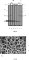
- FIG. 1 shows a first embodiment of a rechargeable battery cell 2 according to the invention in cross-sectional view.
- This rechargeable battery cell 2 is designed as a prismatic cell and has, among other things, a housing 1.
- This housing 1 encloses an electrode arrangement 3, which comprises three positive electrodes 4 and four negative electrodes 5.
- the positive electrodes 4 and the negative electrodes 5 are arranged alternately stacked in the electrode arrangement 3.
- the housing 1 can, however, also accommodate more positive electrodes 4 and/or negative electrodes 5.
- the number of negative electrodes 5 is one greater than the number of positive electrodes 4. This means that the outer end faces of the electrode stack are formed by the electrode surfaces of the negative electrodes 5.
- the electrodes 4, 5 are connected to corresponding connection contacts 9, 10 of the rechargeable battery cell 2 via electrode connections 6, 7.
- the rechargeable battery cell 2 is filled with an SO 2 -based electrolyte in such a way that the electrolyte penetrates as completely as possible into all pores or cavities, in particular within the electrodes 4, 5.
- the electrolyte is in Figure 1 not visible.
- the positive electrodes 4 contain an intercalation compound as active material. This intercalation compound is NaCoO 2 .
- the electrodes 4, 5 are flat, i.e. as layers with a smaller thickness in relation to their surface area. They are each separated from one another by separators 11.
- the housing 1 of the rechargeable battery cell 2 is essentially cuboid-shaped, with the electrodes 4, 5 and the walls of the housing 1 shown in the sectional view extending perpendicular to the plane of the drawing and being essentially straight and flat.
- the electrodes 4, 5 further comprise a discharge element which serves to enable the required electronically conductive connection of the active material of the respective electrode.
- This discharge element is in contact with the active material involved in the electrode reaction of the respective electrode 4, 5 (in Figure 1 not shown).
- the discharge element is in the form of a porous metal foam 18.
- the metal foam 18 extends over the thickness dimension of the electrodes 4, 5.
- the active material of the positive electrodes 4 and the negative electrodes 5 is incorporated into the pores of this metal foam 18 so that it fills its pores evenly over the entire thickness of the metal structure.
- the positive electrodes 4 contain a binder. This binder is a fluoropolymer.
- the negative electrodes 5 contain carbon as the active material in a form suitable as an insertion material for absorbing sodium ions.
- the structure of the negative electrode 5 is similar to that of the positive electrode 4.
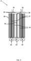
- Figure 2 shows an electron micrograph of the three-dimensional porous structure of the metal foam 18 of the first embodiment of Figure 1 .
- the pores P have an average diameter of more than 100 ⁇ m, i.e. they are relatively large.
- This metal foam is a metal foam made of nickel.
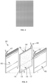
- FIG 3 shows a second embodiment of a rechargeable battery cell 20 according to the invention in cross-sectional view.
- the electrode arrangement comprises a positive electrode 23 and two negative electrodes 22. They are each separated from one another by separators 21 and surrounded by a housing 28.
- the positive electrode 23 has a discharge element 26 in the form of a planar metal foil, to which the active material 24 of the positive electrode 23 is applied on both sides.
- the negative electrodes 22 also comprise a discharge element 27 in the form of a planar metal foil, to which the active material 25 of the negative electrode 22 is applied on both sides.
- the planar discharge elements of the edge electrodes i.e. the electrodes that close off the electrode stack, can only be coated with active material on one side. The uncoated side faces the wall of the housing 28.
- the electrodes 22, 23 are connected via electrode connections 29, 30 to corresponding connection contacts 31, 32 of the rechargeable battery cell 20.
- Figure 4 shows the planar metal foil, which serves as a discharge element 26, 27 for the positive electrodes 23 and the negative electrodes 22 in the second embodiment from Figure 3.
- This metal foil has a perforated or net-like structure with a thickness of 20 ⁇ m.
- FIG. 5 shows a third embodiment of a rechargeable battery cell 40 according to the invention in an exploded view.
- This third embodiment differs from the two previously explained embodiments in that the positive electrode 44 is enclosed by a casing 13.
- a surface area of the casing 13 is larger than a surface area of the positive electrode 44, the boundary 14 of which in Figure 5 is shown as a dashed line.
- Two layers 15, 16 of the casing 13 covering the positive electrode 44 on both sides are connected to one another at the peripheral edge of the positive electrode 44 by an edge connection 17.
- the two negative electrodes 45 are not covered.
- the electrodes 44 and 45 can be contacted via the electrode connections 46 and 47.
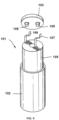
- FIG. 6 shows a third embodiment of a rechargeable battery cell 101 according to the invention in an exploded view.
- the essential construction elements are shown a battery cell 101 with a wound electrode arrangement.
- a cylindrical housing 102 with a cover part 103 there is an electrode arrangement 105 which is wound from a web-shaped starting material.
- the web consists of several layers, which include a positive electrode, a negative electrode and a separator running between the electrodes, which electrically and mechanically insulates the electrodes from one another, but is sufficiently porous or ion-conductive to enable the required ion exchange. In this way, large electrochemically active surfaces are created, which enable a correspondingly high current yield.
- the positive electrode has a discharge element in the form of a planar metal foil, to which a homogeneous mixture of the active material of the positive electrode is applied on both sides.
- the negative electrode also comprises a discharge element in the form of a planar metal foil, to which a homogeneous mixture of the active material of the negative electrode is applied on both sides.
- the cavity of the housing 102 is filled with an electrolyte (not shown) to the extent that it is not occupied by the electrode arrangement 105.
- the positive and negative electrodes of the electrode arrangement 105 are connected via corresponding connection lugs 106 for the positive electrode and 107 for the negative electrode to the connection contacts 108 for the positive electrode and 109 for the negative electrode, which enable the electrical connection of the rechargeable battery cell 101.
- the electrical connection of the negative electrode can also be made via the housing 102.
- this compound Li1 was dissolved in SO2 .
- the concentration of the conducting salt in the reference electrolyte was 0.6 mol/L.
- the compound Na1 shown below was first prepared as a conductive salt according to formula (I) according to a production process described in the following document [V6]: [V6] PJ Malinowski et al, Dalton Trans., 2020, 49, 7766-7773
- electrolyte was 0.6 mol/l (molar concentration based on 1 liter of electrolyte), unless otherwise stated in the experiment description.
- the experiments described below were carried out with the electrolyte Na1 and the reference electrolyte.
- the experiments were carried out in a test cell with a three-electrode arrangement (working electrode, counter electrode and reference electrode) with metallic sodium as counter and reference electrode.
- the working electrode was an electrode with an active material made of hard carbon.
- the composition of the electrode was 96 wt% hard carbon and a total of 4 wt% of the binders CMC and SBR.
- the discharge element was an aluminum foil.
- the half cells were filled with the electrolyte Na1.
- FIG. 7 shows the potentials of the charging curve and the discharging curve for the fifth cycle of the half-cell.
- the dashed curve corresponds to the potentials of the charging curve and the solid curve corresponds to the potentials of the discharging curve.
- the charging and discharging curves show typical battery behavior with a good cycle efficiency of over 95%.
- test cell with a three-electrode arrangement (working electrode, counter electrode and reference electrode) with metallic sodium as counter and reference electrode.
- the working electrode was an aluminum foil.
- the half cells were filled with the electrolyte Na1.
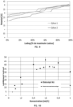
- test cell with a three-electrode arrangement (working electrode, counter electrode and reference electrode) was prepared in an experiment.
- the active material of the positive electrode (cathode) consisted of sodium cobalt oxide with the composition Na 0.7 CoO 2 .
- the composition of the entire positive electrode was 94 wt% Na 0.7 CoO 2 and 4 wt% of the binder PVDF and 2 wt% carbon black.
- the discharge element was a foil made of aluminum.
- the counter electrode and the reference electrode consisted of metallic sodium.
- the test cell was filled with the electrolyte Na1.
- test cell was charged at a charge rate of 0.1 C to an upper potential of 4.2 V. It was then discharged at a discharge rate of 0.1 C to a discharge potential of 2.0 volts.
- Figure 9 shows the potential curve of the first two charge/discharge cycles in volts [V] as a function of the charge in % of the maximum charge.
- the potential curves show stable charging and discharging behavior.
- the curve shape is typical for this type of electrode material.
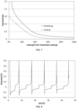
- the Na1 electrolyte was prepared with different concentrations of the compound Na1.
- the conductivity of the electrolyte was determined for each concentration of the compound using a conductive measuring method. After tempering, a four-electrode sensor was held in contact with the solution and measured in a measuring range of 0.02 - 500 mS/cm.
- Figure 10 shows the conductivity of the electrolyte Na1 as a function of the concentration of the compound Na1.
- the conductivity of the reference electrolyte is plotted as a function of the concentration of the corresponding Li compound (see [V4]).
- a maximum conductivity can be seen at a concentration of the compound Na1 of 0.6 mol/L with a high conductivity value of approx. 48 mS/cm.
- the reference electrolyte has a maximum conductivity at a concentration of the compound Li1 of 0.6 mol/L - 0.7 mol/L of approx. 38 mS/cm.
- the electrolyte Na1 with the conducting salt Na1 therefore has a better conductivity than the reference electrolyte with the corresponding lithium compound Li1.
- the sodium ion is larger than the lithium ion, so that better conductivity is also expected for lithium electrolytes.
- Table 1 show the surprising results in terms of conductivity.
- the organic electrolytes known from the state of the art such as LP30 (1 M LiPF6 / EC-DMC (1:1 wt.)) have a conductivity of only about 10 mS/cm.
Landscapes
- Chemical & Material Sciences (AREA)
- General Chemical & Material Sciences (AREA)
- Chemical Kinetics & Catalysis (AREA)
- Electrochemistry (AREA)
- Engineering & Computer Science (AREA)
- Inorganic Chemistry (AREA)
- Manufacturing & Machinery (AREA)
- Materials Engineering (AREA)
- Physics & Mathematics (AREA)
- Condensed Matter Physics & Semiconductors (AREA)
- General Physics & Mathematics (AREA)
- Composite Materials (AREA)
- Secondary Cells (AREA)
- Cell Electrode Carriers And Collectors (AREA)
- Battery Electrode And Active Subsutance (AREA)
Description
- Die Erfindung betrifft eine wiederaufladbare Batteriezelle umfassend Natrium als aktives Metall.
- Wiederaufladbare Batteriezellen sind auf vielen technischen Gebieten von großer Bedeutung. Vielfach werden sie für Anwendungen eingesetzt, bei denen nur kleine wiederaufladbare Batteriezellen mit relativ geringen Stromstärken benötigt werden, wie beispielsweise beim Betrieb von Mobiltelefonen. Daneben gibt es aber auch einen großen Bedarf an größeren wiederaufladbaren Batteriezellen für Hochenergieanwendungen, wobei eine Massenspeicherung von Energie in Form von Batteriezellen für den elektrischen Antrieb von Fahrzeugen von besonderer Bedeutung ist.
- Eine wichtige Anforderung bei derartigen wiederaufladbaren Batteriezellen ist eine hohe Energiedichte. Das bedeutet, dass die wiederaufladbare Batteriezelle möglichst viel elektrische Energie je Gewichts- und Volumeneinheit enthalten soll. Hierfür hat sich Lithium als aktives Metall als besonders vorteilhaft erwiesen. Ein Nachteil von Lithiumzellen liegt jedoch in den begrenzten Ressourcen von Lithium auf der Erde. Deshalb versuchen viele Forschungsgruppen auf diesem Gebiet einen Ersatz für Lithium als aktives Metall zu finden, der von einer Seite die großen Vorteile des Lithiums aufweist aber gleichzeitig leicht zugänglich und kostengünstig ist. Als ein möglicher Ersatz von Lithium wird Natrium untersucht.
- Als aktives Metall einer wiederaufladbaren Batteriezelle bezeichnet man das Metall, dessen Ionen innerhalb des Elektrolyten beim Laden oder Entladen der Zelle zur negativen oder positiven Elektrode wandern und dort an elektrochemischen Prozessen teilnehmen. Diese elektrochemischen Prozesse führen direkt oder indirekt zur Abgabe von Elektronen in den externen Stromkreis oder zur Aufnahme von Elektronen aus dem externen Stromkreis. Aktive Metalle können, wie oben erwähnt, Lithium oder Natrium sein. Wiederaufladbare Batteriezellen, welche Lithium bzw. Natrium als aktives Metall enthalten, werden auch als Lithium-Ionen-Zellen bzw. Natrium-Ionen-Zellen bezeichnet. Lithium-Ionen-Zellen sind schon lange bekannt und sind ausführlich in dem Stand der Technik beschrieben. Im Gegenteil dazu sind die Natrium-Ionen-Zellen erst seit 2010 im Fokus der Forschung und werden hier nachfolgend detaillierter beschrieben. Die meisten Forschungsaktivitäten waren der Entdeckung von Hochleistungsanoden gewidmet, um die Energiedichte von Natrium-Ionen-Batterien zu erhöhen, da Graphit, das hauptsächlich verwendete Material in Lithium-lonen-Zellen, im Vergleich mit Lithium eine viel geringere Speicherkapazität für Natrium aufweist.
- Wie jede wiederaufladbare Batteriezelle weist die Natrium-Ionen-Zelle ein Gehäuse auf, in dem zumindest eine positive Elektrode mit einem Ableitelement, zumindest eine negative Elektrode mit einem Ableitelement und ein Elektrolyt angeordnet sind. Sowohl die positive als auch die negative Elektrode der aus dem Stand der Technik bekannten Natrium-Ionen-Zellen sind als Insertionselektroden ausgebildet. Unter dem Begriff "Insertionselektrode" im Sinne der vorliegenden Erfindung werden Elektroden verstanden, welche eine Kristallstruktur aufweisen, in die Ionen des aktiven Metalls beim Betrieb der Natrium-Ionen-Zelle ein- und ausgelagert werden können. Das bedeutet, dass sich die Elektrodenprozesse nicht nur an der Oberfläche der Elektroden, sondern auch innerhalb der Kristallstruktur abspielen können.
- Auch der Elektrolyt ist ein wichtiges Funktionselement jeder wiederaufladbaren Batteriezelle. Er enthält meistens ein Lösungsmittel oder Lösungsmittelgemisch und mindestens ein Leitsalz. Feststoffelektrolyte oder ionische Flüssigkeiten enthalten zum Beispiel kein Lösungsmittel, sondern nur ein Leitsalz. Der Elektrolyt steht mit der positiven und der negativen Elektrode der Batteriezelle in Kontakt. Mindestens ein Ion des Leitsalzes (Anion oder Kation) ist in dem Elektrolyten derartig beweglich, dass durch lonenleitung ein für die Funktion der wiederaufladbaren Batteriezelle erforderlicher Ladungstransport zwischen den Elektroden stattfinden kann. Der Elektrolyt wird ab einer bestimmten oberen Zellspannung der wiederaufladbaren Batteriezelle oxidativ elektrochemisch zersetzt. Dieser Vorgang führt oft zu einer irreversiblen Zerstörung von Bestandteilen des Elektrolyten und damit zu einem Ausfall der wiederaufladbaren Batteriezelle. Auch reduktive Prozesse können den Elektrolyten ab einer bestimmten unteren Zellspannung zersetzen. Um diese Prozesse zu vermeiden, werden die positive und die negative Elektrode derart gewählt, dass die Zellspannung unter- bzw. oberhalb der Zersetzungsspannung des Elektrolyten liegt. Der Elektrolyt bestimmt somit das Spannungsfenster (in Engl.: voltage window), in dessen Bereich eine wiederaufladbare Batteriezelle reversibel betrieben, das heißt (d.h.) wiederholt aufgeladen und entladen werden kann.
- Die aus dem Stand der Technik bekannten organischen Natrium-Ionen-Zellen enthalten einen Elektrolyten, der aus einem organischen Lösungsmittel oder Lösungsmittelgemisch und einem darin gelösten Leitsalz besteht. Bei dem Leitsalz handelt es sich um ein Natriumsalz wie beispielsweise Natriumperchlorat (NaClO4) oder Natriumhexafluorophosphat (NaPF6). Das organische Lösungsmittelgemisch kann beispielsweise Propylencarbonat (PC) sein. Lösungsmittelgemische können Ethylencarbonat (EC), Diethylcarbonat (DEC) oder Dimethylcarbonat (DMC) enthalten. Es werden zum Beispiel folgende Gemische verwendet: EC:DEC, EC:PC oder EC:DMC.
- Aufgrund der Verwendung des organischen Lösungsmittels oder Lösungsmittelgemischs werden derartige Natrium-Ionen-Zellen auch als organische Natrium-Ionen-Zellen bezeichnet.
- Eine geeignete negative Elektrode für organische Natrium-Ionen-Zellen besteht zum Beispiel aus Kohlenstoff in der Modifikation Hartkohlenstoff (engl. hard carbon). Hartkohlenstoff hat eine Kapazität vom 300 mAh/g und eine Zykeleffizienz im ersten Zyklus von 80%. Positive Elektrode der organischen Natrium-Ionen-Zelle können aus Schichtoxiden wie z.B. NaMeOx oder polyanionschen Verbindungen wie z.B. Phosphaten (NaMePO4), Pyrophosphaten (Na2MeP2O7) und Fluorophosphaten (Na2Me(PO)4F) bestehen, wobei "Me" jeweils für ein Übergangsmetall steht.
- Natrium ist ein sehr elektronegatives Metall (-2,71 V vs. Standard Wasserstoffelektrode, SHE), wodurch eine sehr hohe Zellspannung gegen eine positive Elektrode erzeugt wird. An der negativen Elektrode findet die Reduktion des organischen Elektrolyten statt. Diese reduktive Zersetzung ist irreversibel. Keine organischen Lösungsmittel sind thermodynamisch stabil gegenüber Natrium oder gegenüber Natrium, welches in Kohlenstoff gespeichert ist. Viele Lösungsmittel bilden jedoch einen Passivierungsfilm auf der Elektrodenoberfläche der negativen Elektrode. Dieser Film trennt das Lösungsmittel räumlich von der Elektrode, ist aber ionisch leitfähig und ermöglicht so den Durchgang von Natriumionen. Der Passivierungsfilm, die so genannte "Solid Electrolyte Interphase" (SEI), verleiht dem System Stabilität, wodurch die Herstellung von organischen Natrium-Ionen-Zellen ermöglicht wird. Bei der Bildung der SEI wird Natrium in den Passivierungsfilm integriert. Dieser Prozess ist irreversibel, wodurch ein Kapazitätsverlust beobachtet wird. Dieser irreversible Kapazitätsverlust, der auch als Deckschichtkapazität bezeichnet wird, hängt von der verwendeten Elektrolytformulierung und den verwendeten Elektroden ab. In organischen Natrium-Ionen-Zellen dauert die Elektrolytzersetzung und Bildung von Natriumionen-enthaltenen Schichten während des weiteren Betriebs der organischen Natrium-Ionen-Zelle oft an und ist für den Kapazitätsverlust und damit für eine kürzere Lebenszeit der organischen Natrium-Ionen-Zelle verantwortlich. Deshalb sind organische Natrium-Ionen-Zellen problematisch hinsichtlich ihrer Stabilität sowie langfristigen Betriebssicherheit. Sicherheitsrisiken werden insbesondere auch durch die Brennbarkeit des organischen Lösungsmittels oder Lösungsmittelgemischs verursacht. Wenn eine organische Natrium-Ionen-Zelle Feuer fängt oder sogar explodiert, bildet das organische Lösungsmittel des Elektrolyten ein brennbares Material. Ein weiterer Nachteil von organischen Natrium-Ionen-Zellen besteht in der Zersetzung der organischen Bestandteile der SEI-Schicht und der damit verbundenen Freisetzung giftiger Gase. Zusätzlich findet dadurch eine weitere Erwärmung der Zelle statt. Um solche Sicherheitsrisiken zu vermeiden, müssen zusätzliche Maßnahmen getroffen werden. Zu diesen Maßnahmen zählen insbesondere eine sehr exakte Regelung der Lade- und Entladevorgänge der organischen Natrium-Ionen-Zelle. Die zusätzlichen Maßnahmen werden jedoch bei einer möglichen Vermarktung als nachteilig bewertet.
- Eine aus dem Stand der Technik bekannte Weiterentwicklung sieht die Verwendung eines Elektrolyten auf Schwefeldioxid (SO2)-Basis anstatt eines organischen Elektrolyten für wiederaufladbare Batteriezellen vor. Wiederaufladbare Batteriezellen, welche einen auf SO2-basierenden Elektrolyten enthalten, weisen unter anderem eine hohe ionische Leitfähigkeit auf. Unter dem Begriff "auf SO2-basierender Elektrolyt" ist ein Elektrolyt zu verstehen, der SO2 nicht nur als Zusatz in geringer Konzentration enthält, sondern bei dem die Beweglichkeit der Ionen des Leitsalzes, das in dem Elektrolyten enthalten ist und den Ladungstransport bewirkt, zumindest teilweise, größtenteils oder sogar vollständig durch SO2 gewährleistet ist. Das SO2 dient also als Lösungsmittel für das Leitsalz. Das Leitsalz kann mit dem gasförmigen SO2 einen flüssigen Solvatkomplex bilden, wobei das SO2 gebunden und der Dampfdruck gegenüber dem reinen SO2 merklich gesenkt wird. Es entstehen Elektrolyte mit niederem Dampfdruck. Derartige Elektrolyten auf SO2-Basis haben im Vergleich zu den zuvor beschriebenen organischen Elektrolyten den Vorteil der Nichtbrennbarkeit. Sicherheitsrisiken, welche durch die Brennbarkeit des Elektrolyten bestehen, können dadurch ausgeschlossen werden.
- Hauptsächlich werden auf SO2-basierende Elektrolyte der Zusammensetzung LiAlCl4 * xSO2 verwendet. Aber auch Natrium-Leitsalze wurden untersucht. Die
US 4,891,281 (bezeichnet als [V1]) zeigt Untersuchungen unter anderem mit Lithium- und Natriumleitsalzen, z.B. LiAlCl4 und NaAlCl4, in auf SO2-basierenden Elektrolyten. Dem Dokument entnimmt man jedoch, dass Elektrolyte mit dem Leitsalz NaAlCl4 eine schlechtere Leitfähigkeit zeigen als Elektrolyte mit dem Leitsalz LiAlCl4.DieEP 2 860 799 A1 (bezeichnet als [V2]) offenbart eine wiederaufladbare Alkali-Ionen-Batterie mit einem auf SO2-basierenden Elektrolyten mit der Zusammensetzung NaAlCl4 * xSO2. Ein Beispiel zeigt diesen Elektrolyten in Kombination mit einer Natrium-Metall-Anode und einer kohlenstoffhaltigen Kathode, an der SO2 als aktives Elektrodenmaterial beim Betrieb der Batteriezelle oxidiert bzw. reduziert wird. - Aus der
EP 2 860 811 A1 (bezeichnet als [V3]) geht eine Batteriezelle mit einem Elektrolyten der Zusammensetzung NaAlCl4 * xSO2, einer metall-chlorid-haltigen Kathode und einer Anode, die ein natriumenthaltendes anorganisches Material enthält, hervor. - Neben den in SO2-Elektrolyten gebräuchlichen Alkali-Tetrachloroaluminat-Leitsalzen (z.B. LiAlCl4 * xSO2 oder NaAlCl4 * xSO2) offenbart die
EP 3 772 129 A1 (bezeichnet als [V4]) eine neue Gruppe von Leitsalzen für auf SO2-basierende Elektrolyten. Diese Leitsalze bestehen aus einem Anion mit vier substituierten Hydoxygruppen gruppiert um das Zentralatom Bor oder Aluminium und einem Kation, bestehend aus dem aktiven Metall der Zelle. Alle Beispiele zeigen Experimente ausschließlich mit Lithiumsalzen dieser Art. -
EP 3 794 666 A1 (bezeichnet als [V7]) offenbart ebenfalls eine wiederaufladbare Batteriezelle umfassend einen auf SO2-basierenden Elektrolyten und ein Aluminat- oder Boratsalz als erstes Leitsalz. Als aktives Metall wird ausschließlich Lithium verwendet. - Aus
US 2021/057795 A1 (bezeichnet als [V8]) ist eine Lithium-Luft-Batterie bekannt, die einen Elektrolyten aufweist, der ein Lithiumsalz, ein Natriumsalz in Form von Natrium-Alkylfluoroborat und ein Lösungsmittel umfasst. Der Elektrolyt ist jedoch kein auf SO2-basierender Elektrolyt. - Ein Problem bei den auf SO2-basierenden Elektrolyten besteht darin, dass viele, insbesondere auch für organische Natrium-Ionen-Zellen bekannte Leitsalze nicht in SO2 löslich sind und somit solche Leitsalze für den Einsatz bei wiederaufladbaren Natrium-Ionen-Zellen mit einem auf SO2-basierenden Elektrolyten ungeeignet sind.
- Somit liegt die der vorliegenden Erfindung zugrunde liegende Aufgabe eine wiederaufladbare Batteriezelle bereitzustellen, die gegenüber den aus dem Stand der Technik bekannten wiederaufladbaren Batteriezellen:
- keine Verwendung von Lithium vorsieht,
- einen auf SO2-basierenden Elektrolyten enthält, der eine für Leitsalze gute Löslichkeit aufweist und damit ein guter lonenleiter und elektronischer Isolator ist, damit der ionentransport erleichtert und die Selbstentladung auf ein Minimum beschränkt werden kann;
- einen auf SO2-basierenden Elektrolyten enthält, der auch gegenüber anderen Komponenten der wiederaufladbaren Batteriezelle, wie Separatoren, Elektrodenmaterialien und Zellverpackungsmaterialien, inert ist;
- ein breites elektrochemisches Fenster hat, sodass keine oxidative Elektrolytzersetzung an der positiven Elektrode auftritt;
- eine stabile Deckschicht auf der negativen Elektrode aufweist, wobei die Deckschichtkapazität niedrig sein sollte und im weiteren Betrieb keine weitere reduktive Elektrolytzersetzung an der negativen Elektrode auftritt;
- gegen verschiedene Missbräuche, wie elektrische, mechanische oder thermische, robust ist;
- einen auf SO2-basierenden Elektrolyten enthält, der aus wirtschaftlicher Sicht günstige und leicht zu beschaffendende Rohstoffe enthält.
- das Ableitelement der negativen Elektrode auch ein Ableiter aus Aluminium sein kann.
- Derartige wiederaufladbare Batteriezellen sollen insbesondere auch sehr gute elektrische Energie- und Leistungsdaten, eine hohe Betriebssicherheit und Lebensdauer, insbesondere eine hohe Zahl nutzbarer Lade- und Entladezyklen aufweisen, ohne dass sich hierbei der Elektrolyt im Betrieb der wiederaufladbaren Batteriezelle zersetzt.
- Die der vorliegenden Erfindung zugrunde liegende Aufgabe wurde überraschenderweise durch eine wiederaufladbare Batteriezelle mit den Merkmalen des Anspruchs 1 gelöst. Die Ansprüche 2 bis 20 beschreiben vorteilhafte Weiterbildungen der erfindungsgemäßen wiederaufladbaren Batteriezelle. Weitere vorteilhafte Weiterbildungen der erfindungsgemäßen wiederaufladbaren Batteriezelle sind der Beschreibung, den Beispielen und den Zeichnungen zu entnehmen.
- Eine erfindungsgemäße wiederaufladbare Batteriezelle enthält ein aktives Metall, zumindest eine positive Elektrode, zumindest eine negative Elektrode, ein Gehäuse und einen Elektrolyten, wobei das aktive Metall Natrium ist. Der Elektrolyt basiert auf SO2 und enthält zumindest ein erstes Leitsalz, welches die Formel (I)

- einem oder mehreren Halogenatomen, insbesondere Fluor, oder
- einer chemischen Gruppe, die ausgewählt ist aus der Gruppe bestehend aus C1-C4-Alkyl, C2-C4-Alkenyl, C2-C4-Alkinyl, Phenyl, Benzyl, und vollständig oder teilweise halogeniertem, insbesondere vollständig oder teilweise fluoriertem C1-C4-Alkyl, C2-C4-Alkenyl, C2-C4-Alkinyl, Phenyl und Benzyl.
- Unter der Formulierung "Chelatligand, der mindestens von zwei der Substituenten R1, R2, R3 und R4 gemeinsam gebildet wird und an Z koordiniert ist" ist im Sinne der vorliegenden Erfindung zu verstehen, dass zumindest zwei der Substituenten R1, R2, R3 und R4 untereinander verbrückt sein können, wobei diese Verbrückung von zwei Substituenten zu der Bildung eines zweizähnigen Chelatliganden führt. Beispielsweise kann der Chelatligand zweizähnig gemäß der Formel -O-R5-O- ausgebildet sein. Zur Ausbildung dieses Chelatliganden -O-R5-O- kann aus struktureller Hinsicht der erste Substituent R1 bevorzugt eine OR5-Gruppe und der zweite Substituent R2 bevorzugt eine Hydroxygruppe sein, welche in ihrem verbrückten Zustand miteinander durch Ausbildung einer chemischen Bindung verbunden sind und daher die zuvor genannte Formel -O-R5-O- aufweisen. Solche Chelatliganden können beispielsweise die folgenden Strukturformeln aufweisen:

- Der Chelatligand koordiniert an das Zentralatom Z unter Bildung eines Chelatkomplexes. Im Fall des zweizähnigen Chelatliganden -O-R5-O- koordinieren die beiden Sauerstoffatome an das Zentralatom Z. Synthetisch können solche Chelatkomplexe wie in dem nachfolgend beschriebenen Beispiel 1 hergestellt werden. Die Bezeichnung "Chelatkomplex" steht für Komplexverbindungen, bei denen ein mehrzähniger Ligand (besitzt mehr als ein freies Elektronenpaar) mindestens zwei Koordinationsstellen (Bindungsstellen) des Zentralatoms einnimmt. Der Chelatligand kann auch mehrzähnig ausgebildet sein, wenn drei oder vier der Substituenten R1, R2, R3 und R4 jeweils untereinander verbrückt vorliegen. Der in der erfindungsgemäßen wiederaufladbaren Batteriezelle verwendete auf SO2-basierende Elektrolyt enthält SO2 nicht nur als Zusatz in geringer Konzentration, sondern in Konzentrationen, bei denen die Beweglichkeit der Ionen des ersten Leitsalzes, das in dem Elektrolyten enthalten ist und den Ladungstransport bewirkt, zumindest teilweise, größtenteils oder sogar vollständig durch das SO2 gewährleistet ist. Das erste Leitsalz ist in dem Elektrolyten gelöst und zeigt darin eine sehr gute Löslichkeit. Es kann mit dem gasförmigen SO2 einen flüssigen Solvatkomplex bilden, in welchem das SO2 gebunden wird. In diesem Fall sinkt der Dampfdruck des flüssigen Solvatkomplexes gegenüber dem reinen SO2 deutlich und es entstehen Elektrolyte mit niederem Dampfdruck. Es liegt jedoch auch im Rahmen der Erfindung, dass es bei der Herstellung des erfindungsgemäßen Elektrolyten, je nachdem welche chemische Struktur das erste Leitsalz nach Formel (I) hat, zu keiner Dampfdruckerniedrigung kommen kann. Im letztgenannten Fall ist es bevorzugt, dass bei der Herstellung des erfindungsgemäßen Elektrolyten bei Tieftemperatur oder unter Druck gearbeitet wird. Der Elektrolyt kann auch mehrere Leitsalze der Formel (I) enthalten, welche in ihrer chemischen Struktur voneinander abweichen. Der Begriff "C1-C10 Alkyl" umfasst im Sinne der vorliegenden Erfindung lineare oder verzweigte gesättigte Kohlenwasserstoffgruppen mit einem bis zehn Kohlenstoffatomen. Hierunter fallen insbesondere Methyl, Ethyl, n-Propyl, Isopropyl, n-butyl, sec-Butyl, iso-Butyl, tert-Butyl, n-Pentyl, iso-Pentyl, 2,2-Dimethylpropyl, n-Hexyl, iso-Hexyl, 2-Ethylhexyl, n-Heptyl, iso-Heptyl, n-Octyl, iso-Octyl, n-Nonyl, n-Decyl und dergleichen.
- Der Begriff "C2-C10 Alkenyl" umfasst im Sinne der vorliegenden Erfindung ungesättigte lineare oder verzweigte Kohlenwasserstoffgruppen mit zwei bis zehn Kohlenstoffatomen, wobei die Kohlenwasserstoffgruppen zumindest eine C-C-Doppelbindung aufweisen. Hierunter fallen insbesondere Ethenyl, 1-Propenyl, 2- Propenyl, 1-n-Butenyl, 2-n-Butenyl, iso-Butenyl, 1-Pentenyl, 1-Hexenyl, 1-Heptenyl, 1-Octenyl, 1-Nonenyl, 1- Decenyl und dergleichen.
- Der Begriff "C2-C10 Alkinyl" umfasst im Sinne der vorliegenden Erfindung ungesättigte lineare oder verzweigte Kohlenwasserstoffgruppen mit zwei bis zehn Kohlenstoffatomen, wobei die Kohlenwasserstoffgruppen zumindest eine C-C-Dreifachbindung aufweisen. Hierunter fallen insbesondere Ethinyl, 1-Propinyl, 2- Propinyl, 1-n-Butinyl, 2-n-Butinyl, iso-Butinyl, 1-Pentinyl, 1- Hexinyl, 1-Heptinyl, 1-Octinyl, 1-Noninyl, 1- Decinyl und dergleichen.
- Der Begriff "C3-C10 Cycloalkyl" umfasst im Sinne der vorliegenden Erfindung zyklische, gesättigte Kohlenwasserstoffgruppen mit drei bis zehn Kohlenstoffatomen. Hierunter fallen insbesondere Cyclopropyl, Cyclobutyl, Cyclopentyl, Cyclohexyl, Cycloheptyl, Cyclohexyl, Cyclononyl und Cyclodecanyl.
- Der Begriff "C6-C14 Aryl" umfasst im Sinne der vorliegenden Erfindung aromatische Kohlenwasserstoffgruppen mit sechs bis vierzehn ringständigen Kohlenstoffatomen. Hierunter fallen insbesondere Phenyl (C6H5 Gruppe), Naphthyl (C10H7 Gruppe) und Anthracyl (C14H9 Gruppe).
- Der Begriff "C5-C14 Heteroaryl" umfasst im Sinne der vorliegenden Erfindung aromatische Kohlenwasserstoffgruppen mit fünf bis vierzehn ringständigen Kohlenwasserstoffatomen, bei welchen zumindest ein Kohlenwasserstoff-Atom durch ein Stickstoff-, Sauerstoff- oder Schwefel-Atom ersetzt bzw. ausgetauscht ist. Hierunter fallen insbesondere Pyrrolyl, Furanyl, Thiophenyl, Pyrridinyl, Pyranyl, Thiopyranyl und dergleichen. Alle der vorgenannten Kohlenwasserstoffgruppen sind jeweils über das Sauerstoff-Atom an Zentralatom gemäß Formel (I) gebunden.
- Bei allen bereits erwähnten Definitionen der Begriffe ist es ebenfalls im Sinne der vorliegenden Erfindung, dass die aliphatischen, cyclischen, aromatischen und heteroaromatischen Resten/Gruppen unsubstituiert oder substituiert sein können. Bei der Substitution wird ein Wasserstoffatom oder mehrere Wasserstoffatome der aliphatischen, cyclischen, aromatischen und heteroaromatischen Resten/Gruppen durch jeweils ein Atom, wie beispielsweise Fluor oder Chlor, oder eine chemische Gruppe, wie beispielsweise CF3, ersetzt.
- Die erfindungsgemäße wiederaufladbare Batteriezelle benutzt als aktives Metall das kostengünstige und gut erhältliche Natrium und weist somit den ersten großen Vorteil gegenüber den aus dem Stand der Technik bekannten Lithium-Ionen-Zellen auf.
- Ferner hat die erfindungsgemäße wiederaufladbare Batteriezelle mit einem derartigen Elektrolytenden Vorteil gegenüber wiederaufladbaren Batteriezellen mit aus dem Stand der Technik bekannten SO2-basierenden Elektrolyten mit Natriumleitsalzen, dass das darin enthaltene erste Leitsalz der Formel (I) eine höhere Oxidationsstabilität aufweist und infolgedessen im Wesentlichen keine Zersetzung bei höheren Zellspannungen zeigt. Dieser Elektrolyt ist oxidationsstabil bevorzugt mindestens bis zu einem oberen Potential von 3,6 Volt, weiter bevorzugt mindestens bis zu einem oberen Potential von 3,8 Volt, weiter bevorzugt mindestens bis zu einem oberen Potential von 4,0 Volt, weiter bevorzugt mindestens bis zu einem oberen Potential von 4,2 Volt, weiter bevorzugt mindestens bis zu einem oberen Potential von 4,4 Volt und besonders bevorzugt mindestens bis zu einem oberen Potential von 4,6 Volt. Somit kommt es bei der Verwendung der erfindungsgemä-ßen wiederaufladbaren Zelle umfassend einen solchen Elektrolyten zu einer nur geringen oder sogar gar keinen Elektrolytzersetzung innerhalb der Arbeitspotentiale, also im Bereich zwischen der Ladeschlussspannung und der Entladeschlussspannung, beider Elektroden der wiederaufladbaren Batteriezelle.
- Die Lebensdauer der erfindungsgemäßen wiederaufladbaren Batteriezelle, die diesen Elektrolyten enthält, ist gegenüber wiederaufladbaren Batteriezellen, die aus dem Stand der Technik bekannten Elektrolyten enthalten, deutlich verlängert.
- Weiterhin ist die erfindungsgemäße wiederaufladbare Batteriezelle mit einem solchem Elektrolyten auch tieftemperaturfest. Die Leitfähigkeit des Elektrolyten bei tiefen Temperaturen ist ausreichend zum Betrieb einer Batteriezelle.
- Diese Vorteile der erfindungsgemäßen wiederaufladbaren Batteriezelle umfassend den Elektrolyten überwiegen den Nachteil, der dadurch entsteht, dass das erste Leitsalz der Formel (I) eine im Vergleich zu den aus dem Stand der Technik bekannten Natrium-Leitsalzen deutlich höhere Anionengröße aufweist. Diese höhere Anionengröße führt zu einer im Vergleich zur Leitfähigkeit von NaAlCl4 geringeren Leitfähigkeit des ersten Leitsalzes gemäß Formel (I).
- Nachfolgend sind vorteilhafte Weiterbildungen der erfindungsgemäßen wiederaufladbaren Batteriezelle im Hinblick auf die negative Elektrode beschrieben:
Eine vorteilhafte Weiterbildung der erfindungsgemäßen wiederaufladbaren Batteriezelle sieht vor, dass das aktive Material der negativen Elektrode aus metallischem Natrium und / oder mindestens einem natriumspeichernden Material besteht, das ausgewählt ist aus der Gruppe bestehend aus Insertionsmaterialien, Adsorptionsmaterialien, legierungsbildenden Materialien und Konversionsmaterialien. - Das aktive Material der negativen Elektrode ist gemäß einer vorteilhaften Weiterbildung der erfindungsgemäßen wiederaufladbaren Batteriezelle metallisches Natrium. Das bedeutet, dass Natrium auch das aktive Metall der wiederaufladbaren Batterie ist. Dieses wird beim Laden der wiederaufladbaren Batteriezelle auf dem Ableitelement der negativen Elektrode abgeschieden. Das bedeutet, dass die negative Elektrode neben dem metallischen Natrium als aktives Material auch ein Ableitelement umfasst. Dieses Ableitelement dient dazu, den erforderlichen elektronisch leitenden Anschluss des aktiven Materials der negativen Elektrode zu ermöglichen. Hierfür steht das Ableitelement in Kontakt mit dem an der Elektrodenreaktion der negativen Elektrode beteiligten aktiven Material. Beim Entladen der wiederaufladbaren Batteriezelle wird das metallische Natrium in Natriumionen umgewandelt, die von der negativen Elektrode zur positiven Elektrode wandern.
- Eine weitere vorteilhafte Weiterbildung der erfindungsgemäßen wiederaufladbaren Batteriezelle mit metallischem Natrium als aktives Material der negativen Elektrode sieht vor, dass das elektronisch leitende Ableitelement der negativen Elektrode schon vor dem ersten Laden der wiederaufladbaren Batteriezelle metallisches Natrium umfasst, welches vor dem Zusammenbau der Batteriezelle auf das Ableitelement aufgebracht und zusammen mit diesem in die Batteriezelle eingebaut wurde oder welches vor dem Betrieb der Batteriezelle, d.h. vor dem ersten Laden und Entladen durch einen vorangehenden Initialisierungsladevorgang auf dem Ableitelement der negativen Elektrode abgeschieden wurde. Eine weitere vorteilhafte Weiterbildung der erfindungsgemäßen Batteriezelle mit metallischem Natrium als aktives Material der negativen Elektrode sieht vor, dass das Ableitelement der negativen Elektrode zumindest teilweise aus einem natriumspeichernden Material ausgebildet ist. Bei einer solchen Weiterbildung wird beim Laden der Batteriezelle zunächst ein Teil des aus der Elektrodenreaktion resultierenden Natriums in dem elektronisch leitenden Ableitelement aus dem natriumspeichernden Material gespeichert. Beim weiteren Laden der Batteriezelle scheidet sich dann metallisches Natrium auf das elektronisch leitende Ableitelement ab. Beim Entladen wird das metallische Natrium vollständig oder nur zum Teil aufgelöst und gelangt in Form von Ionen in die Wirtsmatrix des aktiven Materials der positiven Elektrode.
- Das aktive Material der negativen Elektrode besteht gemäß einer weiteren vorteilhaften Weiterbildung der erfindungsgemäßen wiederaufladbaren Batteriezelle mindestens aus einem natriumspeichernden Material, das ausgewählt ist aus der Gruppe bestehend aus Insertionsmaterialien, Adsorptionsmaterialien, legierungsbildenden Materialien und Konversions-Materialien.
- Unter dem Begriff "Insertionsmaterialien" werden im Sinne der vorliegenden Erfindung Materialien verstanden, in welchen die Ionen des aktiven Metalls während des Ladens der wiederaufladbare Batteriezelle eingelagert und aus welchem die Ionen des aktiven Metalls während des Entladens der wiederaufladbaren Batteriezelle ausgelagert werden können. Das bedeutet, dass sich die Elektrodenprozesse nicht nur an der Oberfläche der negativen Elektrode, sondern auch im Inneren der negativen Elektrode abspielen können. Unter dem Begriff "Adsorptionsmaterialien" werden im Sinne der vorliegenden Erfindung Materialien verstanden, die im Gegensatz zu Insertionsmaterialien, die eine Struktur aufweisen, in die Ionen des aktiven Metalls beim Betrieb der Natrium-Ionen-Zelle ein- und ausgelagert werden können, lagern sich bei den Adsorptionsmaterialien die Ionen an der Oberfläche an. Bei vielen Materialien finden auch Insertion und Adsorption gleichzeitig statt.
- Unter dem Begriff "legierungsbildenden Materialien" werden im Sinne der vorliegenden Erfindung Materialien verstanden, bei denen es sich im Allgemeinen um Metalle und Metalllegierungen sowie deren Oxide, die mit dem aktiven Metall, wie z.B. Natrium, eine Legierung bilden, wobei diese Legierungsbildung in oder an der negativen Elektrode stattfindet und im Wesentlichen reversibel ist. Im Gegensatz zu Insertionsmaterialien wird das aktive Metall in den Legierungen nicht in eine bereits existente Struktur eingelagert. Die Einlagerung des aktiven Metalls erfolgt vielmehr über Phasenumwandlungsprozesse, die beispielsweise bei Verwendung von Natrium als aktives Metall zu einem natriumhaltigen, binären Endprodukt führen können. Bei der Legierungsbildung kann es zu einer Ausdehnung des aktiven Materials kommen.
- Unter dem Begriff "Konversionsmaterialien" werden im Sinne der vorliegenden Erfindung Materialien verstanden, welche während der Elektrodenprozesse eine chemische Konversion bzw. Umwandlung durchlaufen, die zu der reversiblen Bildung einer chemischen Verbindung zwischen dem aktiven Metall und dem aktiven Material führt.
- Eine weitere vorteilhafte Weiterbildung der erfindungsgemäßen wiederaufladbaren Batteriezelle sieht vor, dass das natriumspeichernde Material vorzugsweise das Insertionsmaterial enthaltend Kohlenstoff sein kann. Unter dem Begriff "Insertionsmaterialien aus Kohlenstoff" werden im Sinne der vorliegenden Erfindung Materialien aus dem Element Kohlenstoff verstanden, die unter den oben definierten Begriff "Insertionsmaterialien" fallen. Eine weitere vorteilhafte Weiterbildung der erfindungsgemäßen wiederaufladbaren Batteriezelle sieht vor, dass das Insertionsmaterial enthaltend Kohlenstoff ausgewählt ist aus der Gruppe bestehend aus Hartkohlenstoff (engl. hard carbon), Weichkohlenstoff (engl. soft carbon), Graphen oder heteroatom gedopten Kohlenstoffen. Hartkohlenstoff (hard carbon) kann z.B. aus der Carbonisierung einer Vielzahl von Vorstufen wie z. B. Biomasse, Lignin, Cellulose und viele Arten von Polymeren synthetisiert werden. Kohlenstoffhaltige Materialien aus fossilen Brennstoffen (Koks, Pech usw.) sind im Allgemeinen als weich (graphitierbar) angesehen, und beschreiben die Gruppe Weichkohlenstoffe (soft carbon). Heteroatom gedopte Kohlenstoffe sind Kohlenstoffe, die in ihrer Struktur oder an der Oberfläche neben den Kohlenstoffatomen zusätzliche Atome zum Beispiel Stickstoff, Sauerstoff, Schwefel oder Phosphor enthalten.
- Eine weitere vorteilhafte Weiterbildung der erfindungsgemäßen wiederaufladbaren Batteriezelle sieht vor, dass das Insertionsmaterial enthaltend Kohlenstoff Hartkohlenstoff (engl. hard carbon) ist.
- Eine weitere vorteilhafte Weiterbildung der erfindungsgemäßen wiederaufladbaren Batteriezelle sieht vor, dass das Insertionsmaterial enthaltend Kohlenstoff Weichkohlenstoff (engl. soft carbon) ist.
- Eine weitere vorteilhafte Weiterbildung der erfindungsgemäßen wiederaufladbaren Batteriezelle sieht vor, dass das Insertionsmaterial enthaltend Kohlenstoff Graphen ist.
- Eine weitere vorteilhafte Weiterbildung der erfindungsgemäßen wiederaufladbaren Batteriezelle sieht vor, dass das Insertionsmaterial enthaltend Kohlenstoff heteroatom gedopter Kohlenstoff ist.
- Eine weitere vorteilhafte Weiterbildung der erfindungsgemäßen wiederaufladbaren Batteriezelle sieht vor, dass die Natriumionen auch an der Oberfläche adsorbiert werden können.
- Eine weitere vorteilhafte Weiterbildung der erfindungsgemäßen wiederaufladbaren Batteriezelle sieht vor, dass das natriumspeichernde Material der negativen Elektrode aus mindestens einem kohlenstofffreien Insertionsmaterial besteht, wie beispielsweise Natrium-Titanate, insbesondere Na2Ti3O7 oder NaTi2(PO4)3. Unter dem Begriff "kohlenstofffreie Insertionsmaterialien" werden im Sinne der vorliegenden Erfindung Materialien aus einem anderen Element als Kohlenstoff verstanden, die unter den oben definierten Begriff "Insertionsmaterialien" fallen.
- Eine weitere vorteilhafte Weiterbildung der erfindungsgemäßen wiederaufladbaren Batteriezelle sieht vor, dass das natriumspeichernde Material der negativen Elektrode aus mindestens einem Natriumlegierungsbildendem Material besteht. Unter dem Begriff "Natriumlegierungsbildendem Material" werden im Sinne der vorliegenden Erfindung legierungsbildende Materialien wie oben definiert verstanden, die mit Natrium eine Legierung bilden. Als legierungsbildende Materialien können beispielsweise Natrium-speichernde Metalle und Metalllegierungen (z.B. Sn, Sb,) verwendet werden. Alternativ können Sulfide oder Oxide der Natrium-speichernden Metalle und Metalllegierungen (z.B. SnSx, SbSx, oxidische Gläser von Sn, Sb und dergleichen) als legierungsbildende Materialien sein.
- Eine weitere vorteilhafte Weiterbildung der erfindungsgemäßen wiederaufladbaren Batteriezelle sieht vor, dass die mit Natrium legierungsbildenden Anodenaktivmaterialien schon vor der Verwendung in einer Batteriezelle Natrium enthalten. Diese Maßnahme verringert die Kapazitätsverluste z.B. durch die Deckschichtbildung im ersten Zyklus.
- Eine weitere vorteilhafte Weiterbildung der erfindungsgemäßen wiederaufladbaren Batteriezelle sieht vor, dass das natriumspeichernde Material der negativen Elektrode aus mindestens einem natriumspeichernden Material besteht, welches ein Konversionsmaterial ist, wie oben definiert. Das Konversionsmaterial kann ausgewählt werden aus der Gruppe bestehend aus Sulfiden, Oxiden, Seleniden und Fluoriden der Metalle Ti, V, Cr, Mn, Fe, Co, Ni, Cu und Zn, insbesondere von Eisensulfiden (FeSx), Eisenseleniden (FeSex), Eisenfluoriden (FeFx), Eisenoxiden (FeOx), Cobaltoxiden (CoOx), Nickeloxiden (NiOx) und Kupferoxiden (CuOx).
- Eine weitere vorteilhafte Weiterbildung der erfindungsgemäßen wiederaufladbaren Batteriezelle sieht vor, dass die negative Elektrode aus einer Kombination der oben beschriebenen natriumspeichernden Materialien besteht. Zum Beispiel könnte eine Kombination von Zinn (Sb) und/oder Zinnsulfid (SnSx) und Hartkohlenstoff (engl. hard carbon) verwendet werden.
- Eine weitere vorteilhafte Weiterbildung der erfindungsgemäßen wiederaufladbaren Batteriezelle sieht vor, dass die negative Elektrode porös ist, wobei die Porosität bevorzugt höchstens 50 %, weiter bevorzugt höchstens 45 %, weiter bevorzugt höchstens 40 %, weiter bevorzugt höchstens 35 %, weiter bevorzugt höchstens 30 %, weiter bevorzugt höchstens 20 % und besonders bevorzugt höchstens 10 % beträgt. Die Porosität stellt das Hohlraumvolumen zu Gesamtvolumen der negativen Elektrode dar, wobei das Hohlraumvolumen von sogenannten Poren bzw. Hohlräumen ausgebildet wird. Diese Porosität führt zu einer Vergrößerung der inneren Oberfläche der negativen Elektrode. Weiterhin verringert die Porosität die Dichte der negativen Elektrode und damit auch ihr Gewicht. Die einzelnen Poren der negativen Elektrode können im Betrieb vorzugsweise vollständig mit dem Elektrolyten gefüllt sein.
- Eine weitere vorteilhafte Weiterbildung der erfindungsgemäßen Batteriezelle sieht vor, dass die negative Elektrode ein Ableitelement aufweist. Das bedeutet, dass die negative Elektrode neben dem aktiven Material bzw. Insertionsmaterial auch ein Ableitelement umfasst. Dieses Ableitelement dient dazu, den erforderlichen elektronisch leitenden Anschluss des aktiven Materials der negativen Elektrode zu ermöglichen. Hierfür steht das Ableitelement in Kontakt mit dem an der Elektrodenreaktion der negativen Elektrode beteiligten aktiven Material. Dieses Ableitelement kann planar in Form eines dünnen Metallblechs oder einer dünnen Metallfolie ausgebildet sein. Die dünne Metallfolie weist vorzugsweise eine durchbrochene bzw. netzartige Struktur auf. Das planare Ableitelement kann auch aus einer mit Metall beschichtetet Kunststofffolie bestehen. Diese Metallbeschichtungen weisen eine Dicke im Bereich von 0,1 µm bis 20µm auf. Das aktive Material der negativen Elektrode ist vorzugsweise auf die Oberfläche des dünnen Metallblechs, der dünnen Metallfolie oder der mit Metall beschichteten Kunststofffolie aufgebracht. Das aktive Material kann auf der Vorder- und/oder der Rückseite des planaren Ableitelements aufgebracht sein. Derartige planare Ableitelemente weisen eine Dicke im Bereich von 5 µm bis 50 µm auf. Eine Dicke des planaren Ableitelements im Bereich von 10 µm bis 30 µm ist bevorzugt. Bei der Verwendung von planaren Ableitelementen kann die negative Elektrode eine Gesamtdicke von mindestens 20 µm, bevorzugt mindestens 40 µm und besonders bevorzugt mindestens 60 µm aufweisen. Die maximale Dicke beträgt höchstens 200 µm, bevorzugt höchstens 150 µm und besonders bevorzugt höchstens 100 µm. Die flächenspezifische Kapazität der negativen Elektrode bezogen auf die Beschichtung einer Seite weist bei der Verwendung eines planaren Ableitelements vorzugsweise mindestens 0,5 mAh/cm2 auf, wobei folgende Werte in dieser Reihenfolge weiter bevorzugt sind: 1 mAh/cm2, 3 mAh/cm2, 5 mAh/cm2, 10 mAh/cm2, 15 mAh/cm2, 20 mAh/cm2. Weiterhin besteht auch die Möglichkeit, dass das Ableitelement dreidimensional in Form einer porösen Metallstruktur, insbesondere in Form eines Metallschaums ausgebildet sein kann. Der Begriff "dreidimensionale poröse Metallstruktur" bezeichnet dabei jede aus Metall bestehende Struktur, die sich nicht nur wie das dünne Metallblech bzw. die Metallfolie über Länge und Breite der flächigen Elektrode erstreckt, sondern auch über deren Dickendimension. Die dreidimensionale poröse Metallstruktur ist derartig porös, dass das aktive Material der negativen Elektrode in die Poren der Metallstruktur eingearbeitet werden kann. Bei der Menge an eingearbeitetem bzw. aufgebrachtem aktivem Material handelt es sich um die Beladung der negativen Elektrode. Wenn das Ableitelement dreidimensional in Form einer porösen Metallstruktur, insbesondere in Form eines Metallschaums ausgebildet ist, dann weist die negative Elektrode vorzugsweise eine Dicke von mindestens 0,2 mm, bevorzugt mindestens 0,3 mm, weiter bevorzugt mindestens 0,4 mm, weiter bevorzugt mindestens 0,5 mm und besonders bevorzugt mindestens 0,6 mm auf. Die Dicke der Elektroden ist in diesem Fall deutlich größer im Vergleich zu negativen Elektroden, welche bei organischen Natrium-Ionen-Zellen Anwendung finden. Eine weitere vorteilhafte Ausgestaltung sieht vor, dass die flächenspezifische Kapazität der negativen Elektrode bei der Verwendung eines dreidimensionalen Ableitelements, insbesondere in Form eines Metallschaums vorzugsweise mindestens 2,5 mAh/cm2 beträgt, wobei folgende Werte in dieser Reihenfolge weiter bevorzugt sind: 5 mAh/cm2, 15 mAh/cm2, 25 mAh/cm2, 35 mAh/cm2, 45 mAh/cm2, 55 mAh/cm2, 65 mAh/cm2, 75 mAh/cm2. Wenn das Ableitelement dreidimensional in Form einer porösen Metallstruktur, insbesondere in Form eines Metallschaums ausgebildet ist, beträgt die Menge des aktiven Materials der negativen Elektrode, d.h. die Beladung der Elektrode, bezogen auf ihre Fläche, mindestens 10 mg/cm2, bevorzugt mindestens 20 mg/cm2, weiter bevorzugt mindestens 40 mg/cm2, weiter bevorzugt mindestens 60 mg/cm2, weiter bevorzugt mindestens 80 mg/cm2 und besonders bevorzugt mindestens 100 mg/cm2. Diese Beladung der negativen Elektrode wirkt sich positiv auf den Ladevorgang sowie den Entladevorgang der wiederaufladbaren Batteriezelle aus.
- Das Ableitelement der negativen Elektrode kann z.B. aus Nickel oder Kupfer bestehen. Das Potential des aktiven Metalls Natrium liegt gegenüber dem Potential des aktiven Metalls Lithium, das z.B. in Lithium-Ionen-Batterien verwendet wird, leicht höher. Dadurch kann für Natriumzellen auch ein Ableiter aus Aluminium eingesetzt werden, ohne dass das Natrium, im Gegensatz zum Lithium, mit dem Aluminium legiert.
- Die negative Elektrode weist in einer weiteren vorteilhaften Weiterbildung der erfindungsgemäßen Batteriezelle zumindest ein Bindemittel auf. Dieses Bindemittel ist vorzugsweise ein fluoriertes Bindemittel, insbesondere ein Polyvinylidenfluorid und/oder ein Terpolymer, das aus Tetrafluorethylen, Hexafluorpropylen und Vinylidenfluorid ausgebildet ist. Es kann jedoch auch ein Bindemittel sein, welches aus einem Polymer besteht, das aus monomeren Struktureinheiten einer konjugierten Carbonsäure oder aus dem Alkali-, Erdalkali- oder Ammoniumsalz dieser konjugierten Carbonsäure oder aus einer Kombination daraus aufgebaut ist. Weiterhin kann das Bindemittel auch aus einem Polymer bestehen, das auf monomeren Styrol- und Butadien-Struktureinheiten basiert. Außerdem kann das Bindemittel auch ein Bindemittel aus der Gruppe der Carboxymethylcellulosen sein. Das Bindemittel liegt in der negativen Elektrode vorzugsweise in einer Konzentration von höchstens 20 Gew%, weiter bevorzugt höchstens 15 Gew%, weiter bevorzugt höchstens 10 Gew%, weiter bevorzugt höchstens 7 Gew%, weiter bevorzugt höchstens 5 Gew% und besonders bevorzugt höchstens 2 Gew% bezogen auf das Gesamtgewicht der negativen Elektrode vor.
- Die negative Elektrode weist in einer weiteren vorteilhaften Weiterbildung der erfindungsgemäßen Batteriezelle zumindest ein Leitfähigkeitsadditiv auf. Das Leitfähigkeitsadditiv sollte bevorzugt ein geringes Gewicht, eine hohe chemische Beständigkeit und eine hohe spezifische Oberfläche aufweisen, Beispiele für Leitfähigkeitsadditive sind partikulärer Kohlenstoff (carbon black, Super P, acetylen black), faserartiger Kohlenstoff (CarbonNanoTtubes CNT, Kohelnstoff(nano)fasern), feinverteilte Graphite und Graphen(-Nanos-heets).
- Nachfolgend sind vorteilhafte Weiterbildungen der wiederaufladbaren Batteriezelle im Hinblick auf den auf SO2-basierenden Elektrolyten beschrieben.
- Eine erste vorteilhafte Weiterbildung der erfindungsgemäßen wiederaufladbaren Batteriezelle sieht vor, dass die Substituenten R1, R2, R3 und R4 des ersten Leitsalzes unabhängig voneinander die Struktur der chemischen Gruppe -OR5 aufweisen, wobei R5 ausgewählt ist aus der Gruppe bestehend aus C1-C10 Alkyl, C2-C10 Alkenyl, C2-C10 Alkinyl, C3-C10 Cycloalkyl, C6-C14 Aryl und C5-C14 Heteroaryl, wobei die aliphatischen, cyclischen, aromatischen und heteroaromatischen Gruppen unsubstituiert oder substituiert sein können.
- Eine weitere vorteilhafte Weiterbildung der erfindungsgemäßen wiederaufladbaren Batteriezelle sieht vor, dass der Substituent R5 ausgewählt aus der Gruppe bestehend aus
- C1-C6 Alkyl, bevorzugt C2-C4 Alkyl, besonders bevorzugt 2-Propyl, Methyl und Ethyl;
- C2-C6 Alkenyl, bevorzugt C2-C4 Alkenyl, besonders bevorzugt Ethenyl und Propenyl;
- C2-C6-Alkinyl, bevorzugt C2-C4-Alkinyl;
- C3-C6 Cycloalkyl;
- Phenyl; und
- C5-C7 Heteroaryl;
- wobei die aliphatischen, cyclischen, aromatischen und heteroaromatischen Gruppen unsubstituiert oder substituiert sein können.
- Die Definitionen der Begriffe "C1-C6 Alkyl", "C2-C6 Alkenyl", "C2-C6-Alkinyl", "C3-C6 Cycloalkyl" und "Heteroaryl" sind gleich wie oben bereits definiert.
- Eine weitere vorteilhafte Weiterbildung der erfindungsgemäßen wiederaufladbaren Batteriezelle sieht vor, dass zur Verbesserung der Löslichkeit des ersten Leitsalzes in dem auf SO2-basierenden Elektrolyten zumindest ein einzelnes Atom oder eine Atomgruppe des Substituenten R5 durch ein Halogenatom, insbesondere ein Fluoratom, oder durch eine chemische Gruppe substituiert ist, wobei die chemische Gruppe ausgewählt ist aus der Gruppe bestehend aus C1-C4-Alkyl, C2-C4-Alkenyl, C2-C4-Alkinyl, Phenyl, Benzyl, und voll- und teilhalogeniertem, insbesondere voll- und teilfluoriertem, C1C4-Alkyl, C2-C4-Alkenyl, C2-C4-Alkinyl, Phenyl und Benzyl. Die chemischen Gruppen C1-C4-Alkyl, C2-C4-Alkenyl, C2-C4-Alkinyl, Phenyl und Benzyl weisen dieselben Eigenschaften bzw. chemischen Strukturen auf, wie die zuvor beschriebenen Kohlenwasserstoffgruppen.
- Eine besonders hohe Löslichkeit des ersten Leitsalzes in dem auf SO2-basierenden Elektrolyten kann dadurch erreicht werden, dass zumindest eine Atomgruppe des Substituenten R5 vorzugsweise eine CF3-Gruppe oder eine OSO2CF3-Gruppe ist.
- Eine weitere vorteilhafte Weiterbildung der erfindungsgemäßen wiederaufladbaren Batteriezelle sieht vor, dass die Substituenten R1, R2, R3 und R4 Hydroxygruppen (-OH) sind. Das Wasserstoffatom (H) dieser Hydroxygruppen kann durch eine chemische Gruppe substituiert sein, die ausgewählt ist aus der Gruppe bestehend aus C1-C4-Alkyl, C2-C4-Alkenyl, C2-C4-Alkinyl, Phenyl, Benzyl, und voll- und teilhalogeniertem, insbesondere voll- und teilfluoriertem, C1-C4-Alkyl, C2-C4-Alkenyl, C2-C4-Alkinyl, Phenyl und Benzyl. Die chemischen Gruppen C1-C4-Alkyl, C2-C4-Alkenyl, C2-C4-Alkinyl, Phenyl und Benzyl weisen dieselben Eigenschaften bzw. chemischen Strukturen auf, wie die zuvor beschriebenen Kohlenwasserstoffgruppen und fallen unter die oben ausgeführten Definitionen.
- Eine weitere vorteilhafte Weiterbildung der erfindungsgemäßen wiederaufladbaren Batteriezelle sieht vor, dass das erste Leitsalz ausgewählt aus der Gruppe bestehend aus


- Um die Leitfähigkeit und/oder weitere Eigenschaften des Elektrolyten an einen gewünschten Wert anzupassen, weist der Elektrolyt in einer weiteren vorteilhaften Ausgestaltung der erfindungsgemäßen wiederaufladbaren Batteriezelle zumindest ein zweites, von dem ersten Leitsalz nach Formel (I) abweichendes Leitsalz auf. Das bedeutet, dass der Elektrolyt neben dem ersten Leitsalz ein oder auch weitere zweite Leitsalze enthalten kann, die sich in ihrer chemischen Zusammensetzung sowie ihrer chemischen Struktur von dem ersten Leitsalz unterscheiden.
- In einer weiteren vorteilhaften Ausgestaltung der erfindungsgemäßen wiederaufladbaren Batteriezelle ist das zweite Leitsalz eine Alkalimetallverbindung, insbesondere eine Natriumverbindung. Die Alkalimetallverbindung oder die Natriumverbindung sind ausgewählt aus der Gruppe bestehend aus einem Aluminat, einem Halogenid, einem Oxalat, einem Borat, einem Phosphat, einem Arsenat und einem Gallat. Vorzugsweise ist das zweite Leitsalz ein Natriumtetrahalogenoaluminat, insbesondere NaAlCl4.
- Des Weiteren enthält der Elektrolyt in einer weiteren vorteilhaften Ausgestaltung der erfindungsgemäßen wiederaufladbaren Batteriezelle zumindest ein Additiv. Dieses Additiv ist vorzugsweise ausgewählt aus der Gruppe bestehend aus Vinylencarbonat und seinen Derivaten, Vinylethylencarbonat und seinen Derivaten, Methylethylencarbonat und seinen Derivaten, Natrium(bisoxalato)borat, Natriumdifluor(oxalato)borat, Natriumtetrafluor(oxalato)phosphat, Natriumoxalat, 2-Vinylpyridin, 4-Vinylpyridin, cyclische Exomethylencarbonate, Sultone, cyclische und acyclische Sulfonate, acyclische Sulfite, cyclische und acyclische Sulfinate, organische Ester anorganischer Säuren, acyclische und cyclische Alkane, welche acyclischen und cyclischen Alkane einen Siedepunkt bei 1 bar von mindestens 36 °C aufweisen, aromatische Verbindungen, halogenierte cyclische und acyclische Sulfonylimide, halogenierte cyclische und acyclische Phosphatester, halogenierte cyclische und acyclische Phosphine, halogenierte cyclische und acyclische Phosphite, halogenierte cyclische und acyclische Phosphazene, halogenierte cyclische und acyclische Silylamine, halogenierte cyclische und acyclische halogenierte Ester, halogenierte cyclische und acyclische Amide, halogenierte cyclische und acyclische Anhydride und halogenierte organische Heterocyclen.
- Bezogen auf das Gesamtgewicht der Elektrolytzusammensetzung weist der Elektrolyt in einer weiteren vorteilhaften Weiterbildung der wiederaufladbaren Batteriezelle folgende Zusammensetzung auf:
- (i) 5 bis 99,4 Gew.-% Schwefeldioxid,
- (ii) 0,6 bis 95 Gew.-% des ersten Leitsalzes,
- (iii) 0 bis 25 Gew.-% des zweiten Leitsalzes und
- (iv) 0 bis 10 Gew.-% des Additivs.
- Wie bereits zuvor erwähnt, kann der Elektrolyt nicht nur ein erstes Leitsalz nach Formel (I) und ein zweites Leitsalz enthalten, sondern jeweils auch mehrere erste Leitsalze nach Formel (I) und mehrere zweite Leitsalze. Die zuvor genannten prozentualen Anteile schließen im letztgenannten Fall auch mehrere erste Leitsalze und mehrere zweite Leitsalze ein. Die Stoffmengenkonzentration des ersten Leitsalzes liegt im Bereich von 0,01 mol/l bis 10 mol/l, bevorzugt von 0,05 mol/l bis 10 mol/l, weiter bevorzugt von 0,1 mol/l bis 6 mol/l und besonders bevorzugt von 0,2 mol/l bis 3,5 mol/l bezogen auf das Gesamtvolumen des Elektrolyten.
- Eine weitere vorteilhafte Weiterbildung der erfindungsgemäßen wiederaufladbaren Batteriezelle sieht vor, dass der Elektrolyt mindestens 0,1 Mol SO2, bevorzugt mindestens 1 Mol SO2, weiter bevorzugt mindestens 5 Mol SO2, weiter bevorzugt mindestens 10 Mol SO2 und besonders bevorzugt mindestens 20 Mol SO2 je Mol Leitsalz enthält. Der Elektrolyt kann auch sehr hohe molare Anteile an SO2 enthalten, wobei der bevorzugte obere Grenzwert mit 2600 Mol SO2 je Mol Leitsalz angegeben werden kann und Obergrenzen von 1500, 1000, 500 und 100 Mol SO2 je Mol Leitsalz in dieser Reihenfolge weiter bevorzugt sind. Der Begriff "je Mol Leitsalz" bezieht sich dabei auf alle Leitsalze, die im Elektrolyten enthalten sind. Auf SO2-basierende Elektrolyte mit einem derartigen Konzentrationsverhältnis zwischen SO2 und dem Leitsalz haben den Vorteil, dass sie im Vergleich zu den aus dem Stand der Technik bekannten Elektrolyten, welche beispielsweise auf einem organischen Lösungsmittelgemisch basieren, eine größere Menge an Leitsalz lösen können. Im Rahmen der Erfindung wurde festgestellt, dass überraschenderweise ein Elektrolyt mit einer relativ geringen Konzentration an Leitsalz trotz des damit verbundenen höheren Dampfdrucks vorteilhaft ist, insbesondere hinsichtlich dessen Stabilität über viele Lade- und Entladezyklen der wiederaufladbaren Batteriezelle. Die Konzentration an SO2 im Elektrolyten wirkt sich auf dessen Leitfähigkeit aus. Somit kann durch die Wahl der SO2-Konzentration die Leitfähigkeit des Elektrolyten an die geplante Verwendung einer mit diesem Elektrolyten betriebenen wiederaufladbaren Batteriezelle angepasst werden. Der Gesamtgehalt von SO2 und dem ersten Leitsalz kann größer als 50 Gewichtsprozent (Gew%) des Gewichts des Elektrolyten sein, bevorzugt größer als 60 Gew%, weiter bevorzugt größer als 70 Gew%, weiter bevorzugt größer als 80 Gew%, weiter bevorzugt größer als 85 Gew%, weiter bevorzugt größer als 90 Gew%, weiter bevorzugt größer als 95 Gew% oder weiter bevorzugt größer als 99 Gew%.
- Der Elektrolyt kann mindestens 5 Gew% SO2 bezogen auf die Gesamtmenge des in der wiederaufladbaren Batteriezelle enthaltenen Elektrolyten enthalten, wobei Werte von 20 Gew% SO2, 40 Gew% SO2 und 60 Gew% SO2 weiter bevorzugt sind. Der Elektrolyt kann auch bis zu 95 Gew% SO2 enthalten, wobei Maximalwerte von 80 Gew% SO2 und 90 Gew% SO2 in dieser Reihenfolge bevorzugt sind.
- Es liegt im Rahmen der Erfindung, dass der Elektrolyt vorzugsweise einen nur geringen oder sogar gar keinen prozentualen Anteil an zumindest einem organischen Lösungsmittel aufweist. Vorzugsweise kann der Anteil an organischen Lösungsmitteln im Elektrolyten, welche beispielsweise in Form eines oder einer Mischung mehrerer Lösungsmittel vorhanden ist, höchstens 50 Gew% des Gewichts des Elektrolyten betragen. Besonders bevorzugt sind geringere Anteile von höchstens 40 Gew%, von höchstens 30 Gew%, von höchstens 20 Gew%, von höchstens 15 Gew%, von höchstens 10 Gew%, von höchstens 5 Gew% oder von höchstens 1 Gew% des Gewichts des Elektrolyten. Weiter bevorzugt ist der Elektrolyt frei von organischen Lösungsmitteln. Durch den nur geringen Anteil an organischen Lösungsmitteln oder sogar deren vollständige Abwesenheit ist der Elektrolyt entweder kaum oder gar nicht brennbar. Dies erhöht die Betriebssicherheit einer mit einem derartigen auf SO2-basierenden Elektrolyten betriebenen wiederaufladbaren Batteriezelle.
- Bezogen auf das Gesamtgewicht der Elektrolytzusammensetzung weist der Elektrolyt in einer weiteren vorteilhaften Weiterbildung der wiederaufladbaren Batteriezelle folgende Zusammensetzung auf:
- (i) 5 bis 99,4 Gew.-% Schwefeldioxid,
- (ii) 0,6 bis 95 Gew.-% des ersten Leitsalzes,
- (iii) 0 bis 25 Gew.-% des zweiten Leitsalzes,
- (iv) 0 bis 10 Gew.-% des Additivs und
- (v) 0 bis 50 Gew.-% eines organischen Lösungsmittels.
- Nachfolgend sind vorteilhafte Weiterbildungen der erfindungsgemäßen wiederaufladbaren Batteriezelle im Hinblick auf die positive Elektrode beschrieben:
Eine erste vorteilhafte Weiterbildung der erfindungsgemäßen wiederaufladbaren Batteriezelle sieht vor, dass die positive Elektrode bevorzugt mindestens bis zu einem oberen Potential von 3,6 Volt, weiter bevorzugt mindestens bis zu einem oberen Potential von 3,8 Volt, weiter bevorzugt mindestens bis zu einem oberen Potential von 4,0 Volt, weiter bevorzugt mindestens bis zu einem oberen Potential von 4,2 Volt, weiter bevorzugt mindestens bis zu einem oberen Potential von 4,4 Volt und besonders bevorzugt bis zu einem oberen Potential von 4,6 Volt ladbar ist. - Die positive Elektrode enthält in einer weiteren vorteilhaften Weiterbildung der erfindungsgemäßen wiederaufladbaren Batteriezelle mindestens ein aktives Material. Dieses kann Ionen des aktiven Metalls Natrium speichern und während des Betriebs der Batteriezelle die Ionen des aktiven Metalls Natrium abgeben und wieder aufnehmen.
- Die positive Elektrode enthält in einer weiteren vorteilhaften Weiterbildung der erfindungsgemäßen wiederaufladbaren Batteriezelle zumindest eine Interkalationsverbindung. Unter dem Begriff "Interkalationsverbindung" ist im Sinne der vorliegenden Erfindung eine Unterkategorie der zuvor beschriebenen Insertionsmaterialien zu verstehen. Diese Interkalationsverbindung fungiert als Wirtsmatrix, welche Leerstellen aufweist, die untereinander verbunden sind. In diese Leerstellen können die Ionen des aktiven Metalls während des Entladevorgangs der wiederaufladbaren Batteriezelle eindiffundieren und dort eingelagert werden. Im Rahmen dieser Einlagerung der Ionen des aktiven Metalls kommt es in der Wirtsmatrix nur zu geringen oder gar keinen strukturellen Änderungen.
- Die positive Elektrode enthält in einer weiteren vorteilhaften Weiterbildung der erfindungsgemäßen wiederaufladbaren Batteriezelle als aktives Material zumindest eine Umwandlungsverbindung. Unter dem Begriff "Umwandlungsverbindungen" sind im Sinne der vorliegenden Erfindung Materialien zu verstehen, die während der elektrochemischen Aktivität andere Materialien formen; d.h. während des Ladens und Entladens der Batteriezelle werden chemische Bindungen gebrochen und neu geknüpft. Während der Aufnahme oder Abgabe der Ionen des aktiven Metalls kommt es in der Matrix der Umwandlungsverbindung zu strukturellen Änderungen.
- Das aktive Material weist in einer weiteren vorteilhaften Weiterbildung der erfindungsgemäßen wiederaufladbaren Batteriezelle die Zusammensetzung NaxM'yM"zOa auf, worin
- M' mindestens ein Metall ist, das ausgewählt ist aus der Gruppe bestehend aus den Elementen Ti, V, Cr, Mn, Fe, Co, Ni, Cu und Zn;
- M" mindestens ein Element ist, das ausgewählt ist aus der Gruppe bestehend ausden Elementen der Gruppen 2, 3, 4, 5, 6, 7, 8, 9, 10, 11, 12, 13, 14, 15 und 16 des Periodensystems der Elemente;
- x und y unabhängig voneinander Zahlen größer 0 sind;
- z eine Zahl größer oder gleich 0 ist; und
- a eine Zahl größer 0 ist
- Die Indizes y und z in der Zusammensetzung NaxM'yM"zOa beziehen sich dabei auf die Gesamtheit der Metalle und Elemente, die durch M' bzw. M" repräsentiert werden. Umfasst zum Beispiel M' zwei Metalle M'1 und M'2, so gilt für den Index y: y=y1+y2, wobei y1 und y2 die Indizes der Metalle M'1 und M'2 darstellen. Die Indizes x, y, z und a müssen so gewählt werden, dass eine Ladungsneutralität innerhalb der Zusammensetzung herrscht. Beispiele für Verbindungen bei denen M' zwei Metalle umfasst sind Natriumnickelmangancobaltoxide der Zusammensetzung NaxNiy1Mny2CozO2 mit M'1=Ni, M'2=Mn und M"=Co. Beispiele für Verbindungen in denen z=0 ist, die also kein weiteres Metall oder Element M" aufweisen sind Natriumkobaltoxide NaxCoyOa.
- Umfasst zum Beispiel M" zwei Elemente, zum einen ein Metall M"1 und zum anderen Phosphor als M"2, so gilt für den Index z: z=z1+z2, wobei z1 und z2 die Indizes des Metalls M"1 und des Phosphors (M"2) darstellen. Die Indizes x, y, z und a müssen so gewählt werden, dass eine Ladungsneutralität innerhalb der Zusammensetzung herrscht. Beispiele für Verbindungen bei denen M" ein Metall M"1 und Phosphor als M"2 umfasst sind Natriumeisenmanganphosphate NaxFeyMnz1Pz2O4 mit M`=Fe, M"1=Mn und M"2=P und z2=1. In einer weiteren Zusammensetzung kann M" zwei Nichtmetalle, zum Beispiel Fluor als M"1 und Schwefel als M"2, umfassen. Beispiele für solche Verbindungen sind Natriumeisenfluorsulfate NaxFeyFz1Sz2O4 mit M`=Fe, M"1=F und M"2=P.
- Eine weitere vorteilhafte Weiterbildung der erfindungsgemäßen wiederaufladbaren Batteriezelle sieht vor, dass die Verbindungen NaxM'yM"zOa die Strukturen von Schichtoxiden aufweisen. Dabei können M' oder M" zwei oder mehr Metalle M'1, M'2, M'3 etc. oder M"1, M"2, M"3 etc. sein. Beispiele für solche Verbindungen sind NaNi0.5Mn0.2Ti0.3O3, Na0.90Cu0.22Fe0.30Mn0.48O2, Na2/3Ni2/3Te1/3O2, Na2/3Fe1/2Mn1/2O2, NaxMnO2, NaFe1/2Mn1/2O2, Na(Fe1/3Mn1/3Ni1/3)O2, und Na[Ni0.4Fe0.2Mn0.2Ti0.2]O2. Bevorzugt sind Verbindungen bei denen M' aus den Metallen Nickel und Mangan besteht und M" Cobalt ist, sodass die Verbindung die Formel NaxNiy1Mny2CozOa, aufweist, wobei y1 und y2 unabhängig voneinander Zahlen größer 0 sind. Es kann sich dabei um Zusammensetzungen der Formel Nax[Niy1Mny2Coz]O2 (NMC) handeln, d.h. um Natriumnickelmangancobaltoxide, die die Struktur von Schichtoxiden aufweisen. Beispiele für diese aktiven Materialien aus Natriumnickelmangancobaltoxid sind Na[Ni1/3Mn1/3Co1/3]O2 und Na0.6[Ni0.25Mn0.5Co0.25]O2.
- Eine weitere vorteilhafte Weiterbildung der erfindungsgemäßen wiederaufladbaren Batteriezelle sieht vor, dass die Zusammensetzung die Formel NaxM'yM"zO4 aufweist. Bei diesen Verbindungen handelt es sich um Spinell-Strukturen. Zum Beispiel können M' Kobalt und M" Mangan sein. In diesem Fall handelt es sich bei dem aktiven Material um Natriumcobaltmanganoxid (NaCoMnO4).
- In einer weiteren vorteilhaften Weiterbildung weist die Verbindung die Zusammensetzung NaxM'yM"1 z1M"2 z2Oa auf, wobei M"1 und M"2 jeweils mindestens ein Element ist, das ausgewählt ist aus der Gruppe bestehend aus den Elementen der Gruppen 2, 3, 4, 5, 6, 7, 8, 9, 10, 11, 12, 13, 14, 15 und 16 des Periodensystems der Elemente und wobei M"2 zusammen mit Oa mindestens eine Polyanion-Struktureinheit bilden. Bei der Polyanion-Struktureinheit kann es sich zum Beispiel um Strukturen der Zusammensetzungen (M"2O4)n-, (M"2 mO3m+1)n- oder (M"2O3)n- handeln, worin m und n unabhängig voneinander Zahlen grö-ßer 0 sind. Beispiele für solche Anionen sind (SO4)2-, (PO4)3-, (SiO4)2-, (AsO4)3-, (MoO4)2-, (WO4)2-, (P2O7)4-, (CO3)2- und (BO3)3-.
- Ist M"2 das Element Phosphor, so handelt es sich bei der Verbindung mit der Zusammensetzung NaxM'yM"z1M"z2Oa um sogenannte Natriummetallphosphate. Beispiele für diese Verbindungen sind Na3V2(PO4)3, NaVPO4F, Na2CoP2O7, Na4Ni3(PO4)2P2O7, Na2MnPO4F und Na2MnP2O7. Ist M"2 das Element Schwefel, so handelt es sich bei der Verbindung mit der Zusammensetzung NaxM'yM"z1M"z2Oa um sogenannte Natriummetallsulfate. Beispiele für diese Verbindungen sind NaFeSO4F und NaFe2(PO4)(SO4)2. Bei der zweiten Verbindung handelt es sich um eine Verbindung mit zwei Polyanion-Struktureinheiten. Ist M"2 das Element Silizium, so handelt es sich bei der Verbindung mit der Zusammensetzung NaxM'yM"z1M"z2Oa um sogenannte Natriummetallsilikate. Ein Beispiel für diese Verbindungen ist Na2FeSiO4.
- Das aktive Material weist in einer weiteren vorteilhaften Weiterbildung der erfindungsgemäßen wiederaufladbaren Batteriezelle die Zusammensetzung NaxM'y[Fe(CN)6]a • nH2O auf, wobei M' mindestens ein Metall ist, das ausgewählt ist aus der Gruppe bestehend aus den Elementen Ti, V, Cr, Mn, Fe, Co, Ni, Cu und Zn. Dabei kann M' zwei oder mehr Metalle M'1, M'2, M'3 etc. sein. Dann gilt für den Index y: y=y1+y2, wobei y1 und y2 die Indizes der Metalle M'1 und M'2 darstellen. n ist eine Zahl größer oder gleich Null. x, alle Indices y (y, y1, y2 etc.) und a sind unabhängig voneinander Zahlen größer 0. Bei dieser Art von Verbindungen handelt es sich um Hexacyanoferrate, auch bekannt unter den englischen Bezeichnungen "Prussian blue" und "Prussian white". Beispiele für solche Verbindungen sind Na2NiFe(CN)6, FeFe(CN)6 • 4H2O, Na0.61FeFe(CN)6, Na1.89Mn[Fe(CN)6]0.97 und NaNi0.3Mn0.7 Fe(CN)6.
- Die positive Elektrode enthält als aktives Material in einer weiteren vorteilhaften Weiterbildung der erfindungsgemäßen wiederaufladbaren Batteriezelle zumindest ein aktives Material, welches eine Umwandlungsverbindung darstellt. Umwandlungsverbindungen durchlaufen während der Aufnahme des aktiven Metalls, z.B. Natrium, eine Festkörper-Redoxreaktion bei der sich die Kristallstruktur des Materials ändert. Dieses geschieht unter dem Aufbrechen und Rekombinieren von chemischen Bindungen. Vollständig reversible Reaktionen von Umwandlungsverbindungen können z.B. folgendermaßen lauten:
Typ A: MXz + y Na ↔ M + z Na(y/z)X Typ B: X + y Na ↔ NayX - Die Umwandlungsverbindungen sind ausgewählt aus der Gruppe bestehend aus Sulfiden, Oxiden, Seleniden und Fluoriden der Metalle Ti, V, Cr, Mn, Fe, Co, Ni, Cu und Zn, insbesondere von Eisensulfiden (FeSx), Eisenseleniden (FeSex), Eisenfluoriden (FeFx), Eisenoxiden (FeOx), Cobaltoxiden (CoOx), Nickeloxiden (NiOx) und Kupferoxiden (CuOx).
- Eine weitere vorteilhafte Weiterbildung der erfindungsgemäßen wiederaufladbaren Batteriezelle sieht vor, dass die positive Elektrode zumindest eine Metallverbindung enthält. Diese Metallverbindung ist ausgewählt aus der Gruppe bestehend aus von einem Metalloxid, einem Metallhalogenid und einem Metallphosphat. Vorzugsweise ist das Metall dieser Metallverbindung ein Übergangsmetall der Ordnungszahlen 22 bis 28 des Periodensystems der Elemente, insbesondere Kobalt, Nickel, Mangan oder Eisen.
- Eine weitere vorteilhafte Weiterbildung der erfindungsgemäßen wiederaufladbaren Batteriezelle sieht vor, dass die positive Elektrode zumindest eine Metallverbindung enthält, die die chemische Struktur eines Schichtoxids, eines Spinells, einer Polyanionischen Verbindung oder einer Umwandlungsverbindung hat.
- Es liegt im Rahmen der Erfindung, dass die positive Elektrode als aktives Material mindestens eine der beschriebenen Verbindungen oder eine Kombination der Verbindungen enthält. Unter einer Kombination der Verbindungen versteht man eine positive Elektrode, die mindestens zwei der beschriebenen Materialien enthält.
- Eine weitere vorteilhafte Weiterbildung der erfindungsgemäßen Batteriezelle sieht vor, dass die positive Elektrode ein Ableitelement aufweist. Das bedeutet, dass die positive Elektrode neben dem aktiven Material auch ein Ableitelement umfasst. Dieses Ableitelement dient dazu, den erforderlichen elektronisch leitenden Anschluss des aktiven Materials der positiven Elektrode zu ermöglichen. Hierfür steht das Ableitelement in Kontakt mit dem an der Elektrodenreaktion der positiven Elektrode beteiligten aktiven Material. Dieses Ableitelement kann planar in Form eines dünnen Metallblechs oder einer dünnen Metallfolie ausgebildet sein. Die dünne Metallfolie weist vorzugsweise eine durchbrochene bzw. netzartige Struktur auf. Das planare Ableitelement kann auch aus einer mit Metall beschichtetet Kunststofffolie bestehen. Diese Metallbeschichtungen weisen eine Dicke im Bereich von 0,1 µm bis 20µm auf. Das aktive Material der positiven Elektrode ist vorzugsweise auf die Oberfläche des dünnen Metallblechs, der dünnen Metallfolie oder der mit Metall beschichteten Kunststofffolie aufgebracht. Das aktive Material kann auf der Vorder- und/oder der Rückseite des planaren Ableitelements aufgebracht sein. Derartige planare Ableitelemente weisen eine Dicke im Bereich von 5 µm bis 50 µm auf. Eine Dicke des planaren Ableitelements im Bereich von 10 µm bis 30 µm ist bevorzugt. Bei der Verwendung von planaren Ableitelementen kann die positive Elektrode eine Gesamtdicke von mindestens 20 µm, bevorzugt mindestens 40 µm und besonders bevorzugt mindestens 60 µm aufweise. Die maximalen Dicke beträgt höchstens 200 µm, bevorzugt höchstens 150 µm und besonders bevorzugt höchstens 100 µm. Die flächenspezifische Kapazität der positiven Elektrode bezogen auf die Beschichtung einer Seite weist bei der Verwendung eines planaren Ableitelements vorzugsweise mindestens 0,5 mAh/cm2 auf, wobei folgende Werte in dieser Reihenfolge weiter bevorzugt sind: 1 mAh/cm2, 3 mAh/cm2, 5 mAh/cm2, 10 mAh/cm2, 15 mAh/cm2, 20 mAh/cm2.
- Weiterhin besteht auch die Möglichkeit, dass das Ableitelement der positiven Elektrode dreidimensional in Form einer porösen Metallstruktur, insbesondere in Form eines Metallschaums ausgebildet ist. Die dreidimensionale poröse Metallstruktur ist derartig porös, dass das aktive Material der positiven Elektrode in die Poren der Metallstruktur eingearbeitet werden kann. Bei der Menge an eingearbeitetem bzw. aufgebrachten aktivem Material handelt es sich um die Beladung der positiven Elektrode. Wenn das Ableitelement dreidimensional in Form einer porösen Metallstruktur, insbesondere in Form eines Metallschaums ausgebildet ist, dann weist die positive Elektrode vorzugsweise eine Dicke von mindestens 0,2 mm, bevorzugt mindestens 0,3 mm, weiter bevorzugt mindestens 0,4 mm, weiter bevorzugt mindestens 0,5 mm und besonders bevorzugt mindestens 0,6 mm auf. Eine weitere vorteilhafte Ausgestaltung sieht vor, dass die flächenspezifische Kapazität der positiven Elektrode bei der Verwendung eines dreidimensionalen Ableitelements, insbesondere in Form eines Metallschaums vorzugsweise mindestens 2,5 mAh/cm2 beträgt, wobei folgende Werte in dieser Reihenfolge weiter bevorzugt sind: 5 mAh/cm2, 15 mAh/cm2, 25 mAh/cm2, 35 mAh/cm2, 45 mAh/cm2, 55 mAh/cm2, 65 mAh/cm2, 75 mAh/cm2. Wenn das Ableitelement dreidimensional in Form einer porösen Metallstruktur, insbesondere in Form eines Metallschaums ausgebildet ist, beträgt die Menge des aktiven Materials der positiven Elektrode, d.h. die Beladung der Elektrode, bezogen auf ihre Fläche, mindestens 10 mg/cm2, bevorzugt mindestens 20 mg/cm2, weiter bevorzugt mindestens 40 mg/cm2, weiter bevorzugt mindestens 60 mg/cm2, weiter bevorzugt mindestens 80 mg/cm2 und besonders bevorzugt mindestens 100 mg/cm2. Diese Beladung der positiven Elektrode wirkt sich positiv auf den Ladevorgang sowie den Entladevorgang der wiederaufladbaren Batteriezelle aus.
- Die positive Elektrode weist in einer weiteren vorteilhaften Weiterbildung der erfindungsgemäßen Batteriezelle zumindest ein Bindemittel auf. Dieses Bindemittel ist vorzugsweise ein fluoriertes Bindemittel, insbesondere ein Polyvinylidenfluorid und/oder ein Terpolymer, das aus Tetrafluorethylen, Hexafluorpropylen und Vinylidenfluorid ausgebildet ist. Es kann jedoch auch ein Bindemittel sein, welches aus einem Polymer besteht, das aus monomeren Struktureinheiten einer konjugierten Carbonsäure oder aus dem Alkali-, Erdalkali- oder Ammoniumsalz dieser konjugierten Carbonsäure oder aus einer Kombination daraus aufgebaut ist. Weiterhin kann das Bindemittel auch aus einem Polymer bestehen, das auf monomeren Styrol- und Butadien-Struktureinheiten basiert. Außerdem kann das Bindemittel auch ein Bindemittel aus der Gruppe der Carboxymethylcellulosen sein. Das Bindemittel liegt in der positiven Elektrode vorzugsweise in einer Konzentration von höchstens 20 Gew%, weiter bevorzugt höchstens 15 Gew%, weiter bevorzugt höchstens 10 Gew%, weiter bevorzugt höchstens 7 Gew%, weiter bevorzugt höchstens 5 Gew% und besonders bevorzugt höchstens 2 Gew% bezogen auf das Gesamtgewicht der positiven Elektrode vor.
- Aufbau der wiederaufladbaren Batteriezelle
Nachfolgend sind vorteilhafte Weiterbildungen der erfindungsgemäßen wiederaufladbaren Batteriezelle im Hinblick auf deren Aufbau beschrieben:
Um die Funktion der wiederaufladbaren Batteriezelle weiter zu verbessern, sieht eine weitere vorteilhafte Weiterbildung der erfindungsgemäßen wiederaufladbaren Batteriezelle vor, dass die wiederaufladbaren Batteriezelle mehrere negative Elektroden und mehrere Hochvoltelektroden umfasst, die alternierend gestapelt in dem Gehäuse angeordnet sind. Hierbei sind die positiven Elektroden und die negativen Elektroden vorzugsweise jeweils durch Separatoren voneinander elektrisch getrennt. Die wiederaufladbare Batteriezelle kann jedoch auch als Wickelzelle ausgebildet sein, bei welcher die Elektroden aus dünnen Lagen bestehen, die zusammen mit einem Separatormaterial aufgewickelt sind. Die Separatoren trennen einerseits die positive Elektrode und die negative Elektrode räumlich und elektrisch und sind andererseits unter anderem für die Ionen des aktiven Metalls durchlässig. Auf diese Weise entstehen große elektrochemisch wirksame Oberflächen, die eine entsprechend hohe Stromausbeute ermöglichen. - Der Separator kann aus einem Vlies, einer Membran, einem Gewebe, einem Gewirke, einem organischen Material, einem anorganischen Material oder aus einer Kombination hiervon ausgebildet sein. Organische Separatoren können aus unsubstituierten Polyolefinen (z.B. Polypropylen oder Polyethylen), partiell bis vollständig halogensubstituierten Polyolefinen (z.B. partiell bis ganz fluorsubstituiert, insbesondere PVDF, ETFE, PTFE), Polyestern, Polyamiden oder Polysulfonen bestehen. Separatoren, die eine Kombination von organischen und anorganischen Materialien enthalten, sind zum Beispiel Glasfaser-Textilmaterialien, bei denen die Glasfasern mit einer geeigneten Polymeren Beschichtung versehen sind. Die Beschichtung enthält vorzugsweise ein fluorhaltiges Polymer wie beispielsweise Polytetrafluorethylen (PTFE), Ethylen-Tetrafluorethylen (ETFE), Perfluorethylenpropylen (FEP), THV (Terpolymer aus Tetrafluorethylen, Hexafluorethylen und Vinylidenfluorid), ein Perfluoralkoxy-Polymer (PFA), Aminosilan, Polypropylen oder Polyethylen (PE). Der Separator kann im Gehäuse der wiederaufladbaren Batteriezelle auch gefaltet vorliegen, beispielsweise in Form eines sogenannten "Z-Foldings". Bei diesem Z-Folding ist ein streifenförmiger Separator durch bzw. um die Elektroden z-artig gefaltet. Weiterhin kann der Separator auch als Separatorpapier ausgebildet sein.
- Es liegt auch im Rahmen der Erfindung, dass der Separator als Umhüllung ausgebildet sein kann, wobei jede Hochvoltelektrode oder jede negative Elektrode von der Umhüllung umhüllt ist. Die Umhüllung kann aus einem Vlies, einer Membran, einem Gewebe, einem Gewirke, einem organischen Material, einem anorganischen Material oder aus einer Kombination hiervon ausgebildet sein.
- Eine Umhüllung der positiven Elektrode führt zu einer gleichmäßigeren Ionenwanderung und Ionenverteilung in der wiederaufladbaren Batteriezelle. Je gleichmäßiger die Ionenverteilung, insbesondere in der negativen Elektrode ist, desto höher kann die mögliche Beladung der negativen Elektrode mit aktivem Material und infolgedessen die nutzbare Kapazität der wiederaufladbaren Batteriezelle sein. Gleichzeitig werden Risiken vermieden, die mit einer ungleichmäßigen Beladung und einer daraus resultierenden Abscheidung des aktiven Metalls verbunden sein können. Diese Vorteile wirken sich vor allem aus, wenn die positiven Elektroden der wiederaufladbaren Batteriezelle mit der Umhüllung umhüllt sind.
- Die Flächenmaße der Elektroden und der Umhüllung können vorzugsweise solcherart aufeinander abgestimmt sein, dass die Außenabmessungen der Umhüllung der Elektroden und die Außenabmessungen der nicht umhüllten Elektroden mindestens in einer Dimension übereinstimmen.
- Die Flächenausdehnung der Umhüllung kann vorzugsweise größer als die Flächenausdehnung der Elektrode sein. In diesem Fall erstreckt sich die Umhüllung über eine Begrenzung der Elektrode hinaus. Zwei die Elektrode beidseitig bedeckende Schichten der Umhüllung können daher am Rand der positiven Elektrode durch eine Randverbindung miteinander verbunden werden.
- In einer weiteren vorteilhaften Ausgestaltung der erfindungsgemäßen wiederaufladbaren Batteriezelle weisen die negativen Elektroden eine Umhüllung auf, während die positiven Elektroden keine Umhüllung haben.
- Weitere vorteilhafte Eigenschaften der Erfindung werden nachfolgend anhand von Figuren, Beispielen und Experimenten näher beschrieben und erläutert.
- Figur 1:
- zeigt ein erstes Ausführungsbeispiel einer erfindungsgemäßen wiederaufladbaren Batteriezelle in einer Querschnittsdarstellung;
- Figur 2:
- zeigt eine elektronenmikroskopische Aufnahme der dreidimensionalen porösen Struktur des Metallschaums des ersten Ausführungsbeispiels aus Figur 1 als Detaildarstellung;
- Figur 3:
- zeigt ein zweites Ausführungsbeispiel einer erfindungsgemäßen wiederaufladbaren Batteriezelle in einer Querschnittsdarstellung;
- Figur 4:
- zeigt ein Detail des zweiten Ausführungsbeispiels aus
Figur 3 ; - Figur 5:
- zeigt ein drittes Ausführungsbeispiel der erfindungsgemäßen wiederaufladbaren Batteriezelle in einer Explosionsdarstellung;
- Figur 6:
- zeigt ein drittes Ausführungsbeispiel der erfindungsgemäßen wiederaufladbaren Batteriezelle in einer Explosionsdarstellung;
- Figur 7:
- zeigt das Potenzial in [V] einer Testzelle mit einer Drei-Elektrodenanordnung beim Laden und Entladen der negativen Elektroden mit Hartkohlenstoff als aktives Elektrodenmaterialien als Funktion der Kapazität;
- Figur 8:
- zeigt das Potenzial in [V] einer Testzelle mit einer Drei-Elektrodenanordnung beim mehrmaligen Laden und Entladen der negativen Elektroden mit metallischem Natrium als aktives Elektrodenmaterial als Funktion der Zeit;
- Figur 9:
- zeigt den Potentialverlauf in Volt als Funktion der Kapazität von dem Zyklus 1 und dem Zyklus 2 einer Testzelle mit einer Drei-Elektrodenanordnung mit Natriumcobaltoxid als aktives Material der positiven Elektrode;
- Figur 10:
- zeigt die Leitfähigkeit in [mS/cm] des Elektrolyten Na1 und des Referenzelektrolyten in Abhängigkeit von der Konzentration der Leitsalze.
-
Figur 1 zeigt ein erstes Ausführungsbeispiel einer erfindungsgemäßen wiederaufladbaren Batteriezelle 2 in Querschnittsdarstellung. Diese wiederaufladbare Batteriezelle 2 ist als prismatische Zelle ausgebildet und weist unter anderem ein Gehäuse 1 auf. Dieses Gehäuse 1 umschließt eine Elektrodenanordnung 3, die drei positive Elektroden 4 und vier negative Elektroden 5 umfasst. Die positiven Elektroden 4 und die negativen Elektroden 5 sind in der Elektrodenanordnung 3 alternierend gestapelt angeordnet. Das Gehäuse 1 kann jedoch auch mehr positive Elektroden 4 und/oder negative Elektroden 5 aufnehmen. Generell ist es bevorzugt, wenn die Anzahl der negativen Elektroden 5 um eins größer als die Anzahl der positiven Elektroden 4 ist. Dies hat zur Folge, dass die äußeren Stirnflächen des Elektrodenstapels von den Elektrodenoberflächen der negativen Elektroden 5 gebildet werden. Die Elektroden 4, 5 sind über Elektrodenanschlüsse 6, 7 mit entsprechenden Anschlusskontakten 9, 10 der wiederaufladbaren Batteriezelle 2 verbunden. Die wiederaufladbare Batteriezelle 2 ist derart mit einem auf SO2-basierenden Elektrolyten gefüllt, dass der Elektrolyt möglichst vollständig in sämtliche Poren bzw. Hohlräume, insbesondere innerhalb der Elektroden 4, 5, eindringt. Der Elektrolyt ist inFigur 1 nicht sichtbar. Im vorliegenden Ausführungsbeispiel enthalten die positiven Elektroden 4 eine Interkalationsverbindung als aktives Material. Bei dieser Interkalationsverbindung handelt es sich um NaCoO2. - Die Elektroden 4, 5 sind im vorliegenden Ausführungsbeispiel flächig ausgebildet, d.h. als Schichten mit einem im Verhältnis zu ihrer Flächenausdehnung geringeren Dicke. Sie sind jeweils durch Separatoren 11 voneinander getrennt. Das Gehäuse 1 der wiederaufladbaren Batteriezelle 2 ist im Wesentlichen quaderförmig ausgebildet, wobei sich die Elektroden 4, 5 und die in Schnittdarstellung gezeigten Wände des Gehäuses 1 senkrecht zu der Zeichenebene erstrecken und im Wesentlichen gerade und eben geformt sind.
- Die Elektroden 4, 5 weisen weiterhin ein Ableitelement auf, welches dazu dient, den erforderlichen elektronisch leitenden Anschluss des aktiven Materials der jeweiligen Elektrode zu ermöglichen. Dieses Ableitelement steht in Kontakt zu dem an der Elektrodenreaktion der jeweiligen Elektrode 4, 5 beteiligten aktiven Material (in
Figur 1 nicht dargestellt). Das Ableitelement ist in Form eines porösen Metallschaums 18 ausgebildet. Der Metallschaum 18 erstreckt sich über die Dickendimension der Elektroden 4, 5. Das aktive Material der positiven Elektroden 4 und der negativen Elektroden 5 ist in die Poren dieses Metallschaums 18 eingearbeitet, sodass es dessen Poren über die gesamte Dicke der Metallstruktur gleichmäßig füllt. Zur Verbesserung der mechanischen Festigkeit enthalten die positiven Elektroden 4 ein Bindemittel. Bei diesem Bindemittel handelt es sich um ein Fluorpolymer. Die negativen Elektroden 5 enthalten als aktives Material Kohlenstoff in einer als Insertionsmaterial zur Aufnahme von Natriumionen geeigneten Form. Die Struktur der negativen Elektrode 5 ist ähnlich wie bei der positiven Elektrode 4. -
Figur 2 zeigt eine elektronenmikroskopische Aufnahme der dreidimensionalen porösen Struktur des Metallschaums 18 des ersten Ausführungsbeispiels ausFigur 1 . Anhand des angegebenen Maßstabes ist zu erkennen, dass die Poren P im Mittel einen Durchmesser von mehr als 100 µm haben, also verhältnismäßig groß sind. Bei diesem Metallschaum handelt es sich um einen Metallschaum aus Nickel. -
Figur 3 zeigt ein zweites Ausführungsbeispiel einer erfindungsgemäßen wiederaufladbaren Batteriezelle 20 in Querschnittsdarstellung. Dieses zweite Ausführungsbeispiel unterscheidet sich von dem inFigur 1 gezeigten, ersten Ausführungsbeispiel dadurch, dass die Elektrodenanordnung eine positive Elektrode 23 und zwei negative Elektroden 22 umfasst. Sie sind jeweils durch Separatoren 21 voneinander getrennt und von einem Gehäuse 28 umgeben. Die positive Elektrode 23 weist ein Ableitelement 26 in Form einer planaren Metallfolie auf, auf welche das aktive Material 24 der positiven Elektrode 23 beidseitig aufgebracht ist. Die negativen Elektroden 22 umfassen ebenfalls ein Ableitelement 27 in Form einer planaren Metallfolie, auf welche das aktive Material 25 der negativen Elektrode 22 beidseitig aufgebracht ist. Alternativ können die planaren Ableitelemente der Randelektroden, also der Elektroden, die den Elektrodenstapel abschließen, nur einseitig mit aktivem Material beschichtetet sein. Die nicht-beschichtete Seite zeigt zur Wand des Gehäuses 28. Die Elektroden 22, 23 sind über Elektrodenanschlüsse 29, 30 mit entsprechenden Anschlusskontakten 31, 32 der wiederaufladbaren Batteriezelle 20 verbunden. -
Figur 4 zeigt die planare Metallfolie, welche jeweils als Ableitelement 26, 27 für die positive Elektroden 23 und die negativen Elektroden 22 im zweiten Ausführungsbeispiel aus Figur 3 dient. Diese Metallfolie weist eine durchbrochene bzw. netzartige Struktur mit einer Dicke von 20 µm auf. -
Figur 5 zeigt ein drittes Ausführungsbeispiel einer erfindungsgemäßen wiederaufladbaren Batteriezelle 40 in Explosionsdarstellung. Dieses dritte Ausführungsbeispiel unterscheidet sich von den beiden zuvor erläuterten Ausführungsbeispielen dadurch, dass die positive Elektrode 44 von einer Umhüllung 13 umhüllt ist. Dabei ist eine Flächenausdehnung der Umhüllung 13 größer als eine Flächenausdehnung der positiven Elektrode 44, deren Begrenzung 14 inFigur 5 als gestrichelte Linie eingezeichnet ist. Zwei, die positive Elektrode 44 beidseitig bedeckende Schichten 15, 16 der Umhüllung 13 sind am umlaufenden Rand der positiven Elektrode 44 durch eine Randverbindung 17 miteinander verbunden. Die beiden negativen Elektroden 45 sind nicht umhüllt. Die Elektroden 44 und 45 können über die Elektrodenanschlüsse 46 und 47 kontaktiert werden. -
Figur 6 zeigt ein drittes Ausführungsbeispiel einer erfindungsgemäßen wiederaufladbaren Batteriezelle 101 in Explosionsdarstellung. Gezeigt sind die wesentlichen Konstruktionselemente einer Batteriezelle 101 mit einer gewickelten Elektrodenanordnung. In einem zylindrischen Gehäuse 102 mit einem Deckelteil 103 befindet sich eine Elektrodenanordnung 105, die aus einem bahnförmigen Ausgangsmaterial gewickelt ist. Die Bahn besteht aus mehreren Schichten, zu denen eine positive Elektrode, eine negative Elektrode und ein zwischen den Elektroden verlaufender Separator gehört, der die Elektroden elektrisch und mechanisch voneinander isoliert, jedoch ausreichend porös bzw. ionenleitend ist, um den erforderlichen Ionenaustausch zu ermöglichen. Auf diese Weise entstehen große elektrochemisch wirksame Oberflächen, die eine entsprechend hohe Stromausbeute ermöglichen. Die positive Elektrode weist ein Ableitelement in Form einer planaren Metallfolie auf, auf welche eine homogene Mischung aus dem aktiven Material der positiven Elektrode beidseitig aufgebracht ist. Die negative Elektrode umfasst ebenfalls ein Ableitelement in Form einer planaren Metallfolie, auf welche eine homogene Mischung aus dem aktiven Material der negativen Elektrode beidseitig aufgebracht ist. - Der Hohlraum des Gehäuses 102 ist, soweit er nicht von der Elektrodenanordnung 105 eingenommen wird, mit einem nicht dargestellten Elektrolyten gefüllt. Die positive und negative Elektrode der Elektrodenanordnung 105 sind über entsprechende Anschlussfahnen 106 für die positive Elektrode und 107 für die negative Elektrode mit den Anschlusskontakten 108 für die positive Elektrode und 109 für die negative Elektrode verbunden, die den elektrischen Anschluss der wiederaufladbaren Batteriezelle 101 ermöglichen. Alternativ zu dem in
Figur 6 gezeigten elektrischen Anschluss der negativen Elektrode mittels der Anschlussfahne 107 und dem Anschlusskontakt 109, kann der elektrische Anschluss der negativen Elektrode auch über das Gehäuse 102 erfolgen. - Für die nachfolgend beschriebenen Experimente wurde ein auf SO2-basierender Referenzelektrolyt hergestellt. Hierfür wurde zunächst eine unten dargestellte Verbindung Li1 als Leitsalz gemäß einem in dem folgenden Dokument [V5] beschriebenen Herstellungsverfahren hergestellt:
[V5] "I. Krossing, Chem. Eur. J. 2001, 7, 490; - Diese Verbindung 1 stammt aus der Familie der Polyfluoroalkoxyaluminate und wurde gemäß folgender Reaktionsgleichung ausgehend von LiAlH4 und dem entsprechenden Alkohol R-OH mit R1=R2=R3=R4 in Hexan hergestellt.

- Hierdurch wurde die nachfolgend darstellte Verbindung Li1 mit der folgenden Summen- bzw. Strukturformel gebildet:

- Zur Herstellung des Referenzelektrolyten wurde diese Verbindung Li1 in SO2 gelöst. Die Konzentration des Leitsalzes im Referenzelektrolyten betrug 0,6 mol/L.
- Für die nachfolgend beschriebenen Experimente wurde ein Ausführungsbeispiel des auf SO2-basierenden Elektrolyten hergestellt. Hierfür wurde zunächst die unten dargestellte Verbindung Na1 als Leitsalz nach Formel (I) gemäß einem in dem folgenden Dokument [V6] beschriebenen Herstellungsverfahren hergestellt:
[V6] P. J. Malinowski et al, Dalton Trans., 2020, 49, 7766-7773 Das Leitsalz nach Formel (I) wurde gemäß folgender Reaktionsgleichung ausgehend von NaAlH4 und dem entsprechenden Alkohol R-OH mit R =R2=R3=R4 in Hexan hergestellt.
- Hierdurch wurden die nachfolgend darstellte Verbindung Na1 mit der Summen- bzw. Strukturformel gebildet:


- Danach erfolgte die Lösung der Verbindung Na1 in SO2 bei Tieftemperatur oder unter Druck gemäß den nachfolgend aufgelisteten Verfahrensschritten 1 bis 4:
- 1) Vorlage der jeweiligen Verbindung Na1 in einem Druckkolben mit Steigrohr,
- 2) Evakuieren des Druckkolbens,
- 3) Einströmen von flüssigem SO2 und
- 4) Wiederholung der Schritte 2 + 3 bis die Zielmenge an SO2 zugegeben worden ist.
- Dadurch entstand der Elektrolyt Na1. Die Konzentration der Verbindungen Na1 in dem
- Elektrolyten betrug 0,6 mol/l (Stoffmengenkonzentration bezogen auf 1 Liter des Elektrolyten), sofern in der Experimentbeschreibung nichts Anderes beschrieben ist. Mit dem Elektrolyten Na1 und dem Referenzelektrolyten wurden die nachfolgend beschriebenen Experimente durchgeführt.
- Die Experimente wurden in einer Testzelle mit einer Drei-Elektrodenanordnung (Arbeitselektrode, Gegenelektrode und Bezugselektrode) mit metallischem Natrium als Gegen- und Bezugselektrode durchgeführt. Die Arbeitselektrode war eine Elektrode mit einem Aktivmaterial aus Hartkohlenstoff (engl. hard carbon). Die Zusammensetzung der Elektrode war 96 Gew% Hartkohlenstoff (engl. hard carbon) und insgesamt 4 Gew% der Binder CMC und SBR. Das Ableitelement war eine Folie aus Aluminium. Die Halbzellen wurden mit dem Elektrolyten Na1 befüllt.
- Die Halbzelle wurde mehrmals mit einer Lade-/ Entlade-Rate von 0,1 C bis zu einem Potential von 0,005 Volt geladen und bis zu einem Potential von 1,5 Volt entladen.
Figur 7 zeigt die Potentiale der Ladekurve und Entladekurve für den fünften Zyklus der Halbzelle. Die gestrichelte Kurve entspricht den Potentialen der Ladekurve und die durchgezogene Kurve entspricht den Potentialen der Entladekurve. - Die Lade- und Entladekurven zeigen ein batterietypisches Verhalten mit einer guten Zykeleffizienz von über 95%.
- Die Experimente wurden in einer Testzelle mit einer Drei-Elektrodenanordnung (Arbeitselektrode, Gegenelektrode und Bezugselektrode) mit metallischem Natrium als Gegen- und Bezugselektrode durchgeführt. Die Arbeitselektrode war eine Folie aus Aluminium. Die Halbzellen wurden mit dem Elektrolyten Na1 befüllt.
- Es erfolgte eine wiederholte Abscheidung (Ladung) und Auflösung (Entladung) von metallischem Natrium. Dazu wurden zunächst 0,25 mAh/cm2 Natrium abgeschieden. Danach erfolgte die Entladung bis zu einem Potential von 0,5 Volt. Die Lade- bzw. Entladerate betrug jeweils 0,1 mA/cm2.
Figur 8 zeigt den Potentialverlauf von fünf Lade-/ Entladezyklen über der Zeit. - Die Abscheidung und Auflösung von metallischem Natrium zeigen einen gleichmäßigen Verlauf über die fünf Zyklen.
- Um Natriumcobaltoxid als aktives Elektrodenmaterial für die positive Elektrode in dem Elektrolyten Na1 zu testen, wurde in einem Experiment eine Testzelle mit einer Drei-Elektrodenanordnung (Arbeitselektrode, Gegenelektrode und Bezugselektrode) hergestellt. Das aktive Material der positiven Elektrode (Kathode) bestand aus Natriumcobaltoxid der Zusammensetzung Na0.7CoO2. Die Zusammensetzung der gesamten positiven Elektrode waren 94 Gew% Na0.7CoO2 und 4 Gew% des Binder PVDF und 2 Gew% Carbon Black. Das Ableitelement war eine Folie aus Aluminium. Die Gegenelektrode und die Bezugselektrode bestanden aus metallischem Natrium. Die Testzelle wurde mit dem Elektrolyten Na1 befüllt.
- Die Testzelle wurde mit einer Laderate von 0,1 C bis zu einem oberen Potential von 4,2 V geladen. Danach erfolgte die Entladung mit einer Entladerate von 0,1 C bis zu einem Entladepotential von 2,0 Volt.
Figur 9 zeigt den Potentialverlauf der ersten beiden Lade-/Entladezyklen in Volt [V] als Funktion der Ladung in % der maximalen Ladung. - Die Potentialkurven zeigen ein stabiles Lade- und Entladeverhalten. Der Kurvenverlauf ist typisch für diese Art von Elektrodenmaterial.
- Zur Bestimmung der Leitfähigkeit wurde der Na1-Elektrolyt mit verschiedenen Konzentrationen der Verbindung Na1 hergestellt. Für jede Konzentration der Verbindung wurde die Leitfähigkeit des Elektrolyten bestimmt, indem ein konduktives Messverfahren verwendet wurde. Dabei wurde nach Temperierung ein Vierelektrodensensor berührend in die Lösung gehalten und in einem Messbereich von 0,02 - 500 mS/cm gemessen.
- Die identischen Messungen wurden mit dem Referenzelektrolyten durchgeführt.
-
Figur 10 zeigt die Leitfähigkeit des Elektrolyten Na1 in Abhängigkeit der Konzentration der Verbindung Na1. Zum Vergleich ist die Leitfähigkeit des Referenzelektrolyten in Abhängigkeit der Konzentration der entsprechenden Li-Verbindung (siehe [V4]) aufgetragen. - Zu sehen ist ein Maximum der Leitfähigkeit bei einer Konzentration der Verbindung Na1 von 0,6 mol/L mit einem hohen Leitfähigkeitswert von ca. 48 mS/cm. Im Vergleich hat der Referenzelektrolyt ein Maximum der Leitfähigkeit bei einer Konzentration der Verbindung Li1 von 0,6 mol/L - 0,7 mol/L von ca. 38 mS/cm.
- Der Elektrolyt Na1 mit dem Leitsalz Na1 hat also eine bessere Leitfähigkeit, wie der Referenzelektrolyt mit der entsprechenden Lithiumverbindung Li1. Dies war äußerst überraschend, da zum einen in auf SO2-basierenden Elektrolyten aus dem Stand der Technik die Lithiumverbindung eine bessere Leitfähigkeit gezeigt hat als die Natriumverbindung, wie oben bereits beschreiben (siehe [V1]
US 4,891,281 ). Zum anderen ist das Natrium-Ion größer als das Lithium-Ion, so dass für Lithium-Elektrolyte auch eine bessere Leitfähigkeit erwartet wird. Die in der Tabelle 1 zusammengefassten Ergebnisse der Experimente zeigen die überraschenden Ergebnisse in Bezug auf die Leitfähigkeiten.Tabelle 1: Leitfähigkeiten Leitsalz Leitfähigkeit [mS/cm] Quelle LiAlCl4* 3,5 SO2 100 [V1] NaAlCl4* 2,8 SO2 80 [V1] Referenzelektrolyt (Leitsalz Li1) 38 Maximum Figur 10 Elektrolyt Na1 (Leitsalz Na1) 47 Maximum Figur 10 - Im Vergleich dazu haben die aus dem Stand der Technik bekannten, organischen Elektrolyten, wie z.B. LP30 (1 M LiPF6 / EC-DMC (1:1 Gew.)) eine Leitfähigkeit von nur ca. 10 mS/cm.
Claims (19)
- Wiederaufladbare Batteriezelle (2, 20, 40, 101), enthaltend ein aktives Metall, zumindest eine positive Elektrode (4, 23, 44), zumindest eine negative Elektrode (5, 22, 45), ein Gehäuse (1, 28, 102) und einen Elektrolyten, wobei das aktive Metall Natrium ist,und wobei der Elektrolyt auf SO2 basiert und zumindest ein erstes Leitsalz enthält, welches die Formel (I)
 aufweist, wobei- die Substituenten R1, R2 und R3 unabhängig voneinander ausgewählt sind aus der Gruppe bestehend aus einem Halogenatom, einer Hydroxygruppe und einer chemischen Gruppe -OR5; der Substituent R4 ausgewählt ist aus der Gruppe bestehend aus einer Hydroxygruppe und einer chemischen Gruppe -OR5;- der Substituent R5 ausgewählt ist aus der Gruppe bestehend aus C1-C10 Alkyl, C2-C10 Alkenyl, C2-C10 Alkinyl, C3-C10 Cycloalkyl, C6-C14 Aryl und C5-C14 Heteroaryl, wobei die aliphatischen, cyclischen, aromatischen und heteroaromatischen Gruppen unsubstituiert oder substituiert sein können;- Z Aluminium oder Bor ist;- mindestens zwei der Substituenten R1, R2, R3 und R4 gemeinsam einen Chelatliganden bilden können, der an Z koordiniert ist; und- die aliphatischen, cyclischen, aromatischen und heteroaromatischen Gruppen des Substituenten R5 weiter substituiert werden können mit einem oder mehreren Halogenatomen, insbesondere Fluor, oder einer chemischen Gruppe, die ausgewählt ist aus der Gruppe bestehend aus C1-C4-Alkyl, C2-C4-Alkenyl, C2-C4-Alkinyl, Phenyl, Benzyl, und vollständig oder teilweise halogeniertem, insbesondere vollständig oder teilweise fluoriertem C1-C4-Alkyl, C2-C4-Alkenyl, C2-C4-Alkinyl, Phenyl und Benzyl.
 - Wiederaufladbare Batteriezelle (2, 20, 40, 101) nach Anspruch 1, wobei das aktive Metall Natrium in der negativen Elektrode gespeichert ist als:- metallisches Natrium; und / oder- in mindestens einem natriumspeichernden Material, das ausgewählt ist aus der Gruppe bestehend aus Insertionsmaterialien, Adsorptionsmaterialien, legierungsbildenden Materialien und Konversionsmaterialien.
- Wiederaufladbare Batteriezelle (2, 20, 40, 101) nach Anspruch 2,
bei welcher das natriumspeichernde Material ein Insertionsmaterial enthaltend Kohlenstoff ist, das ausgewählt ist aus der Gruppe bestehend aus Hartkohlenstoff (engl. hard carbon), Weichkohlenstoff (engl. soft carbon), Graphen und heteroatom-gedopten Kohlenstoffen. - Wiederaufladbare Batteriezelle (2, 20, 40, 101) nach Anspruch 2,
bei welcher das natriumspeichernde Material ein kohlenstofffreies Insertionsmaterial ist, vorzugsweise ein Natrium-Titanat, insbesondere Na2Ti3O7 oder NaTi2(PO4)3. - Wiederaufladbare Batteriezelle (2, 20, 40, 101) nach Anspruch 2,
bei welcher das natriumspeichernde Material ein Natriumlegierungsbildendes Material ist, welches ausgewählt ist aus der Gruppe bestehend aus:- natriumspeichernden Metallen und Metalllegierungen vorzugsweise Sn, Sb, oder- Sulfiden und Oxiden der natriumspeichernden Metalle und Metalllegierungen vorzugsweise SnSx, SbSx, oxidische Gläser von Sn, Sb. - Wiederaufladbare Batteriezelle (2, 20, 40, 101) nach Anspruch 2,
bei welcher das natriumspeichernde Material ein Konversionsmaterial ist, welches ausgewählt ist aus der Gruppe bestehend aus Sulfiden, Oxiden, Seleniden und Fluoriden der Metalle Ti, V, Cr, Mn, Fe, Co, Ni, Cu und Zn, vorzugsweise Eisensulfiden (FeSx), Eisenseleniden (FeSex), Eisenfluoriden (FeFx), Eisenoxiden (FeOx), Cobaltoxiden (CoOx), Nickeloxiden (NiOx) und Kupferoxiden (CuOx). - Wiederaufladbare Batteriezelle (2, 20, 40, 101) nach Anspruch 2,
bei welcher die negative Elektrode (5, 22, 45) zumindest ein Natrium legierungsbildendes Anodenmaterial in Kombination mit zumindest einem Insertionsmaterial enthaltend Kohlenstoff aufweist. - Wiederaufladbare Batteriezelle (2, 20, 40, 101) nach einem der vorhergehenden Ansprüche,
bei welcher die positive Elektrode (4, 23, 44) als aktives Material zumindest eine Verbindung enthält, die vorzugsweise die Zusammensetzung NaxM'yM"zOa aufweist, worin- M' mindestens ein Metall ist, das ausgewählt ist aus der Gruppe bestehend aus den Elementen Ti, V, Cr, Mn, Fe, Co, Ni, Cu und Zn;- M" mindestens ein Element ist, das ausgewählt ist aus der Gruppe bestehend aus den Elementen der Gruppen 2, 3, 4, 5, 6, 7, 8, 9, 10, 11, 12, 13, 14, 15 und 16 des Periodensystems der Elemente;- x und y unabhängig voneinander Zahlen größer 0 sind;- z eine Zahl größer oder gleich 0 ist; und- a eine Zahl größer 0 ist. - Wiederaufladbare Batteriezelle (2, 20, 40, 101) nach einem der vorhergehenden Ansprüche,
bei welcher die positive Elektrode (4, 23, 44) mindestens bis zu einem oberen Potential von 3,6 Volt, weiter bevorzugt mindestens bis zu einem oberen Potential von 3,8 Volt, weiter bevorzugt mindestens bis zu einem oberen Potential von 4,0 Volt, weiter bevorzugt mindestens bis zu einem oberen Potential von 4,2 Volt und besonders bevorzugt mindestens bis zu einem oberen Potential von 4,4 Volt in der wiederaufladbaren Batteriezelle ladbar ist. - Wiederaufladbare Batteriezelle (2, 20, 40, 101) nach einem der vorhergehenden Ansprüche,
bei welcher die Substituenten R1, R2, R3 und R4 des ersten Leitsalzes unabhängig voneinander die Struktur der chemischen Gruppe -OR5 aufweisen, wobei R5 ausgewählt ist aus der Gruppe bestehend aus C1-C10 Alkyl, C2-C10 Alkenyl, C2-C10 Alkinyl, C3-C10 Cycloalkyl, C6-C14 Aryl und C5-C14 Heteroaryl, wobei die aliphatischen, cyclischen, aromatischen und heteroaromatischen Gruppen unsubstituiert oder substituiert sein können. - Wiederaufladbare Batteriezelle (2, 20, 40, 101) nach einem der vorhergehenden Ansprüche,
bei welcher der Substituent R5 ausgewählt ist aus der Gruppe bestehend aus- C1-C6 Alkyl, bevorzugt C2-C4 Alkyl, besonders bevorzugt 2-Propyl, Methyl und Ethyl;- C2-C6 Alkenyl, bevorzugt C2-C4 Alkenyl, besonders bevorzugt Ethenyl und Propenyl;- C2-C6-Alkinyl, bevorzugt C2-C4-Alkinyl;- C3-C6 Cycloalkyl;- Phenyl; und- C5-C7 Heteroaryl;- wobei die aliphatischen, cyclischen, aromatischen und heteroaromatischen Gruppen unsubstituiert oder substituiert sein können. - Wiederaufladbare Batteriezelle (2, 20, 40, 101) nach einem der Ansprüche 10 bis 11,
bei welcher der Substituent R5 zumindest mit einer CF3-Gruppe oder einer OSO2CF3-Gruppe substituiert ist. - Wiederaufladbare Batteriezelle (2, 20, 40, 101) nach einem der vorhergehenden Ansprüche,
bei welcher der Chelatligand zweizähnig, insbesondere gemäß der Formel - O-R5-O, oder mehrzähnig ausgebildet ist. - Wiederaufladbare Batteriezelle (2, 20, 40, 101) nach einem der vorhergehenden Ansprüche,
bei welcher das erste Leitsalz ausgewählt ist aus der Gruppe bestehend aus

- Wiederaufladbare Batteriezelle (2, 20, 40, 101) nach einem der vorhergehenden Ansprüche,bei welcher der Elektrolyt die Zusammensetzung5 bis 99,4 Gew.-% Schwefeldioxid,0,6 bis 95 Gew.-% des ersten Leitsalzes,0 bis 25 Gew.-% des zweiten Leitsalzes und0 bis 10 Gew.-% eines Additivs,bezogen auf das Gesamtgewicht der Elektrolytzusammensetzung aufweist.
- Wiederaufladbare Batteriezelle (2, 20, 40, 101) nach einem der vorhergehenden Ansprüche,
bei welcher die Stoffmengenkonzentration des ersten Leitsalzes im Bereich von 0,01 mol/l bis 10 mol/l, bevorzugt von 0,05 mol/l bis 10 mol/l, weiter bevorzugt von 0,1 mol/l bis 6 mol/l und besonders bevorzugt von 0,2 mol/l bis 3,5 mol/l bezogen auf das Gesamtvolumen des Elektrolyten ist. - Wiederaufladbare Batteriezelle (2, 20, 40, 101) nach einem der vorhergehenden Ansprüche,
bei welcher der Elektrolyt mindestens 0,1 Mol SO2, bevorzugt mindestens 1 Mol SO2, weiter bevorzugt mindestens 5 Mol SO2, weiter bevorzugt mindestens 10 Mol SO2 und besonders bevorzugt mindestens 20 Mol SO2 je Mol Leitsalz enthält. - Wiederaufladbare Batteriezelle (2, 20, 40, 101) nach einem der vorhergehenden Ansprüche,
bei welcher die Gesamtheit an organischen Lösungsmitteln im Elektrolyten höchstens 50 Gew% bevorzugt höchstens 40 Gew%, weiter bevorzugt höchstens 30 Gew%, weiter bevorzugt höchstens 20 Gew%, weiter bevorzugt höchstens 15 Gew%, weiter bevorzugt höchstens 10 Gew%, weiter bevorzugt höchstens 5 Gew% weiter bevorzugt höchstens 1 Gew% und besonders bevorzugt der Elektrolyt von organischen Lösungsmittel frei ist. - Wiederaufladbare Batteriezelle (2, 20, 40, 101) nach einem der vorhergehenden Ansprüche,
bei welcher das Ableitelement der negativen Elektrode (5, 22, 45) aus Nickel, Kupfer oder Aluminium ausgebildet ist.
Priority Applications (10)
| Application Number | Priority Date | Filing Date | Title |
|---|---|---|---|
| ES21215533T ES2991388T3 (es) | 2021-12-17 | 2021-12-17 | Celda de batería recargable |
| HUE21215533A HUE068747T2 (hu) | 2021-12-17 | 2021-12-17 | Újratölthetõ akkumulátorcella |
| EP21215533.7A EP4199149B1 (de) | 2021-12-17 | 2021-12-17 | Wiederaufladbare batteriezelle |
| PL21215533.7T PL4199149T3 (pl) | 2021-12-17 | 2021-12-17 | Ogniwo baterii wielokrotnego ładowania |
| KR1020247023893A KR20240122540A (ko) | 2021-12-17 | 2022-12-14 | 이차 전지 셀 |
| CA3241357A CA3241357A1 (en) | 2021-12-17 | 2022-12-14 | Rechargeable battery cell |
| JP2024536049A JP2025500908A (ja) | 2021-12-17 | 2022-12-14 | 充電式電池セル |
| CN202280083707.6A CN118414726A (zh) | 2021-12-17 | 2022-12-14 | 可再充电电池电芯 |
| PCT/EP2022/085941 WO2023111072A1 (de) | 2021-12-17 | 2022-12-14 | Wiederaufladbare batteriezelle |
| US18/743,951 US20240332516A1 (en) | 2021-12-17 | 2024-06-14 | Rechargeable battery cell |
Applications Claiming Priority (1)
| Application Number | Priority Date | Filing Date | Title |
|---|---|---|---|
| EP21215533.7A EP4199149B1 (de) | 2021-12-17 | 2021-12-17 | Wiederaufladbare batteriezelle |
Publications (2)
| Publication Number | Publication Date |
|---|---|
| EP4199149A1 EP4199149A1 (de) | 2023-06-21 |
| EP4199149B1 true EP4199149B1 (de) | 2024-07-17 |
Family
ID=78957304
Family Applications (1)
| Application Number | Title | Priority Date | Filing Date |
|---|---|---|---|
| EP21215533.7A Active EP4199149B1 (de) | 2021-12-17 | 2021-12-17 | Wiederaufladbare batteriezelle |
Country Status (10)
| Country | Link |
|---|---|
| US (1) | US20240332516A1 (de) |
| EP (1) | EP4199149B1 (de) |
| JP (1) | JP2025500908A (de) |
| KR (1) | KR20240122540A (de) |
| CN (1) | CN118414726A (de) |
| CA (1) | CA3241357A1 (de) |
| ES (1) | ES2991388T3 (de) |
| HU (1) | HUE068747T2 (de) |
| PL (1) | PL4199149T3 (de) |
| WO (1) | WO2023111072A1 (de) |
Families Citing this family (1)
| Publication number | Priority date | Publication date | Assignee | Title |
|---|---|---|---|---|
| CN117586294B (zh) * | 2024-01-18 | 2024-05-28 | 山东海化集团有限公司 | 一种四(六氟异丙氧基)硼酸钠的制备方法及其在钠电中的应用 |
Citations (1)
| Publication number | Priority date | Publication date | Assignee | Title |
|---|---|---|---|---|
| EP3794666B1 (de) * | 2019-07-31 | 2021-12-29 | Innolith Technology AG | Wiederaufladbare batteriezelle |
Family Cites Families (4)
| Publication number | Priority date | Publication date | Assignee | Title |
|---|---|---|---|---|
| US4891281A (en) | 1982-08-09 | 1990-01-02 | Duracell Inc. | Electrochemical cells having low vapor pressure complexed SO2 electrolytes |
| KR101520606B1 (ko) | 2013-10-08 | 2015-05-15 | 전자부품연구원 | 나트륨-이산화황계 이차 전지 및 이의 제조 방법 |
| KR101542880B1 (ko) | 2013-10-08 | 2015-08-07 | 전자부품연구원 | 나트륨-금속염화물계 이차 전지 및 그의 제조 방법 |
| US11264659B2 (en) * | 2019-08-20 | 2022-03-01 | Uchicago Argonne, Llc | Rechargeable lithium-hydroxide based non-aqueous lithium oxygen batteries |
-
2021
- 2021-12-17 PL PL21215533.7T patent/PL4199149T3/pl unknown
- 2021-12-17 EP EP21215533.7A patent/EP4199149B1/de active Active
- 2021-12-17 HU HUE21215533A patent/HUE068747T2/hu unknown
- 2021-12-17 ES ES21215533T patent/ES2991388T3/es active Active
-
2022
- 2022-12-14 CA CA3241357A patent/CA3241357A1/en active Pending
- 2022-12-14 JP JP2024536049A patent/JP2025500908A/ja active Pending
- 2022-12-14 WO PCT/EP2022/085941 patent/WO2023111072A1/de not_active Ceased
- 2022-12-14 CN CN202280083707.6A patent/CN118414726A/zh active Pending
- 2022-12-14 KR KR1020247023893A patent/KR20240122540A/ko active Pending
-
2024
- 2024-06-14 US US18/743,951 patent/US20240332516A1/en active Pending
Patent Citations (1)
| Publication number | Priority date | Publication date | Assignee | Title |
|---|---|---|---|---|
| EP3794666B1 (de) * | 2019-07-31 | 2021-12-29 | Innolith Technology AG | Wiederaufladbare batteriezelle |
Also Published As
| Publication number | Publication date |
|---|---|
| US20240332516A1 (en) | 2024-10-03 |
| JP2025500908A (ja) | 2025-01-15 |
| EP4199149A1 (de) | 2023-06-21 |
| WO2023111072A1 (de) | 2023-06-22 |
| CA3241357A1 (en) | 2023-06-22 |
| PL4199149T3 (pl) | 2024-11-25 |
| CN118414726A (zh) | 2024-07-30 |
| HUE068747T2 (hu) | 2025-01-28 |
| KR20240122540A (ko) | 2024-08-12 |
| ES2991388T3 (es) | 2024-12-03 |
Similar Documents
| Publication | Publication Date | Title |
|---|---|---|
| EP3794663B1 (de) | Wiederaufladbare batteriezelle | |
| EP4037056B1 (de) | Auf so2-basierender elektrolyt für eine wiederaufladbare batteriezelle und wiederaufladbare batteriezelle | |
| DE102015111250B4 (de) | Sekundärbatterie mit nicht-wässrigem Elektrolyt, Verfahren zur Herstellung hierfür und nicht-wässrige Elektrolytlösung | |
| EP3734724B1 (de) | Wiederaufladbare batteriezelle | |
| EP3703161A1 (de) | Wiederaufladbare batteriezelle mit einem aktiven elektrodendepolarisator | |
| EP3771011A2 (de) | Auf so2-basierender elektrolyt für eine wiederaufladbare batteriezelle und wiederaufladbare batteriezellen damit | |
| DE112016001116T5 (de) | Elektrolytlösung | |
| EP4037036B1 (de) | Wiederaufladbare batteriezelle | |
| EP4037051B1 (de) | Wiederaufladbare batteriezelle | |
| EP4199149B1 (de) | Wiederaufladbare batteriezelle | |
| WO2023111070A1 (de) | Wiederaufladbare batteriezelle | |
| DE102019133169A1 (de) | Elektrolyt für lithium-sekundärbatterie und diesen enthaltende lithium-sekundärbatterie | |
| DE102016217709A1 (de) | Hybridsuperkondensator mit SEI-Additiven | |
| DE102023107385B3 (de) | Natrium-Ionen-Sekundärbatterie, Verfahren zur Herstellung einer Natrium-Ionen-Sekundärbatterie und deren Verwendung | |
| EP3840091B1 (de) | Zelle mit metallischer lithiumanode und herstellungsverfahren | |
| WO2008110558A1 (de) | Elektrolyte für elektrochemische bauelemente | |
| DE102016217818A1 (de) | Hybridsuperkondensator mit einem Additiv zur Erhöhung der Viskosität |
Legal Events
| Date | Code | Title | Description |
|---|---|---|---|
| PUAI | Public reference made under article 153(3) epc to a published international application that has entered the european phase |
Free format text: ORIGINAL CODE: 0009012 |
|
| STAA | Information on the status of an ep patent application or granted ep patent |
Free format text: STATUS: REQUEST FOR EXAMINATION WAS MADE |
|
| 17P | Request for examination filed |
Effective date: 20220729 |
|
| AK | Designated contracting states |
Kind code of ref document: A1 Designated state(s): AL AT BE BG CH CY CZ DE DK EE ES FI FR GB GR HR HU IE IS IT LI LT LU LV MC MK MT NL NO PL PT RO RS SE SI SK SM TR |
|
| GRAP | Despatch of communication of intention to grant a patent |
Free format text: ORIGINAL CODE: EPIDOSNIGR1 |
|
| STAA | Information on the status of an ep patent application or granted ep patent |
Free format text: STATUS: GRANT OF PATENT IS INTENDED |
|
| RIC1 | Information provided on ipc code assigned before grant |
Ipc: H01M 4/66 20060101ALN20240228BHEP Ipc: H01M 4/587 20100101ALN20240228BHEP Ipc: H01M 4/58 20100101ALN20240228BHEP Ipc: H01M 4/525 20100101ALN20240228BHEP Ipc: H01M 4/485 20100101ALN20240228BHEP Ipc: H01M 4/48 20100101ALN20240228BHEP Ipc: H01M 10/0568 20100101ALI20240228BHEP Ipc: H01M 10/0563 20100101ALI20240228BHEP Ipc: H01M 10/054 20100101ALI20240228BHEP Ipc: H01M 4/38 20060101AFI20240228BHEP |
|
| RIC1 | Information provided on ipc code assigned before grant |
Ipc: H01M 4/66 20060101ALN20240306BHEP Ipc: H01M 4/587 20100101ALN20240306BHEP Ipc: H01M 4/58 20100101ALN20240306BHEP Ipc: H01M 4/525 20100101ALN20240306BHEP Ipc: H01M 4/485 20100101ALN20240306BHEP Ipc: H01M 4/48 20100101ALN20240306BHEP Ipc: H01M 10/0568 20100101ALI20240306BHEP Ipc: H01M 10/0563 20100101ALI20240306BHEP Ipc: H01M 10/054 20100101ALI20240306BHEP Ipc: H01M 4/38 20060101AFI20240306BHEP |
|
| INTG | Intention to grant announced |
Effective date: 20240319 |
|
| P01 | Opt-out of the competence of the unified patent court (upc) registered |
Effective date: 20240419 |
|
| GRAS | Grant fee paid |
Free format text: ORIGINAL CODE: EPIDOSNIGR3 |
|
| GRAA | (expected) grant |
Free format text: ORIGINAL CODE: 0009210 |
|
| STAA | Information on the status of an ep patent application or granted ep patent |
Free format text: STATUS: THE PATENT HAS BEEN GRANTED |
|
| AK | Designated contracting states |
Kind code of ref document: B1 Designated state(s): AL AT BE BG CH CY CZ DE DK EE ES FI FR GB GR HR HU IE IS IT LI LT LU LV MC MK MT NL NO PL PT RO RS SE SI SK SM TR |
|
| REG | Reference to a national code |
Ref country code: CH Ref legal event code: EP |
|
| REG | Reference to a national code |
Ref country code: DE Ref legal event code: R096 Ref document number: 502021004394 Country of ref document: DE |
|
| REG | Reference to a national code |
Ref country code: IE Ref legal event code: FG4D Free format text: LANGUAGE OF EP DOCUMENT: GERMAN |
|
| REG | Reference to a national code |
Ref country code: SE Ref legal event code: TRGR |
|
| REG | Reference to a national code |
Ref country code: LT Ref legal event code: MG9D |
|
| REG | Reference to a national code |
Ref country code: NL Ref legal event code: MP Effective date: 20240717 |
|
| REG | Reference to a national code |
Ref country code: ES Ref legal event code: FG2A Ref document number: 2991388 Country of ref document: ES Kind code of ref document: T3 Effective date: 20241203 |
|
| PG25 | Lapsed in a contracting state [announced via postgrant information from national office to epo] |
Ref country code: PT Free format text: LAPSE BECAUSE OF FAILURE TO SUBMIT A TRANSLATION OF THE DESCRIPTION OR TO PAY THE FEE WITHIN THE PRESCRIBED TIME-LIMIT Effective date: 20241118 |
|
| PG25 | Lapsed in a contracting state [announced via postgrant information from national office to epo] |
Ref country code: NL Free format text: LAPSE BECAUSE OF FAILURE TO SUBMIT A TRANSLATION OF THE DESCRIPTION OR TO PAY THE FEE WITHIN THE PRESCRIBED TIME-LIMIT Effective date: 20240717 |
|
| PG25 | Lapsed in a contracting state [announced via postgrant information from national office to epo] |
Ref country code: PT Free format text: LAPSE BECAUSE OF FAILURE TO SUBMIT A TRANSLATION OF THE DESCRIPTION OR TO PAY THE FEE WITHIN THE PRESCRIBED TIME-LIMIT Effective date: 20241118 Ref country code: NL Free format text: LAPSE BECAUSE OF FAILURE TO SUBMIT A TRANSLATION OF THE DESCRIPTION OR TO PAY THE FEE WITHIN THE PRESCRIBED TIME-LIMIT Effective date: 20240717 |
|
| PG25 | Lapsed in a contracting state [announced via postgrant information from national office to epo] |
Ref country code: NO Free format text: LAPSE BECAUSE OF FAILURE TO SUBMIT A TRANSLATION OF THE DESCRIPTION OR TO PAY THE FEE WITHIN THE PRESCRIBED TIME-LIMIT Effective date: 20241017 |
|
| PG25 | Lapsed in a contracting state [announced via postgrant information from national office to epo] |
Ref country code: FI Free format text: LAPSE BECAUSE OF FAILURE TO SUBMIT A TRANSLATION OF THE DESCRIPTION OR TO PAY THE FEE WITHIN THE PRESCRIBED TIME-LIMIT Effective date: 20240717 Ref country code: GR Free format text: LAPSE BECAUSE OF FAILURE TO SUBMIT A TRANSLATION OF THE DESCRIPTION OR TO PAY THE FEE WITHIN THE PRESCRIBED TIME-LIMIT Effective date: 20241018 |
|
| PG25 | Lapsed in a contracting state [announced via postgrant information from national office to epo] |
Ref country code: BG Free format text: LAPSE BECAUSE OF FAILURE TO SUBMIT A TRANSLATION OF THE DESCRIPTION OR TO PAY THE FEE WITHIN THE PRESCRIBED TIME-LIMIT Effective date: 20240717 |
|
| PG25 | Lapsed in a contracting state [announced via postgrant information from national office to epo] |
Ref country code: LV Free format text: LAPSE BECAUSE OF FAILURE TO SUBMIT A TRANSLATION OF THE DESCRIPTION OR TO PAY THE FEE WITHIN THE PRESCRIBED TIME-LIMIT Effective date: 20240717 |
|
| PG25 | Lapsed in a contracting state [announced via postgrant information from national office to epo] |
Ref country code: IS Free format text: LAPSE BECAUSE OF FAILURE TO SUBMIT A TRANSLATION OF THE DESCRIPTION OR TO PAY THE FEE WITHIN THE PRESCRIBED TIME-LIMIT Effective date: 20241117 |
|
| PG25 | Lapsed in a contracting state [announced via postgrant information from national office to epo] |
Ref country code: HR Free format text: LAPSE BECAUSE OF FAILURE TO SUBMIT A TRANSLATION OF THE DESCRIPTION OR TO PAY THE FEE WITHIN THE PRESCRIBED TIME-LIMIT Effective date: 20240717 |
|
| PG25 | Lapsed in a contracting state [announced via postgrant information from national office to epo] |
Ref country code: RS Free format text: LAPSE BECAUSE OF FAILURE TO SUBMIT A TRANSLATION OF THE DESCRIPTION OR TO PAY THE FEE WITHIN THE PRESCRIBED TIME-LIMIT Effective date: 20241017 |
|
| REG | Reference to a national code |
Ref country code: HU Ref legal event code: AG4A Ref document number: E068747 Country of ref document: HU |
|
| PG25 | Lapsed in a contracting state [announced via postgrant information from national office to epo] |
Ref country code: RS Free format text: LAPSE BECAUSE OF FAILURE TO SUBMIT A TRANSLATION OF THE DESCRIPTION OR TO PAY THE FEE WITHIN THE PRESCRIBED TIME-LIMIT Effective date: 20241017 Ref country code: NO Free format text: LAPSE BECAUSE OF FAILURE TO SUBMIT A TRANSLATION OF THE DESCRIPTION OR TO PAY THE FEE WITHIN THE PRESCRIBED TIME-LIMIT Effective date: 20241017 Ref country code: LV Free format text: LAPSE BECAUSE OF FAILURE TO SUBMIT A TRANSLATION OF THE DESCRIPTION OR TO PAY THE FEE WITHIN THE PRESCRIBED TIME-LIMIT Effective date: 20240717 Ref country code: IS Free format text: LAPSE BECAUSE OF FAILURE TO SUBMIT A TRANSLATION OF THE DESCRIPTION OR TO PAY THE FEE WITHIN THE PRESCRIBED TIME-LIMIT Effective date: 20241117 Ref country code: HR Free format text: LAPSE BECAUSE OF FAILURE TO SUBMIT A TRANSLATION OF THE DESCRIPTION OR TO PAY THE FEE WITHIN THE PRESCRIBED TIME-LIMIT Effective date: 20240717 Ref country code: GR Free format text: LAPSE BECAUSE OF FAILURE TO SUBMIT A TRANSLATION OF THE DESCRIPTION OR TO PAY THE FEE WITHIN THE PRESCRIBED TIME-LIMIT Effective date: 20241018 Ref country code: FI Free format text: LAPSE BECAUSE OF FAILURE TO SUBMIT A TRANSLATION OF THE DESCRIPTION OR TO PAY THE FEE WITHIN THE PRESCRIBED TIME-LIMIT Effective date: 20240717 Ref country code: BG Free format text: LAPSE BECAUSE OF FAILURE TO SUBMIT A TRANSLATION OF THE DESCRIPTION OR TO PAY THE FEE WITHIN THE PRESCRIBED TIME-LIMIT Effective date: 20240717 |
|
| PG25 | Lapsed in a contracting state [announced via postgrant information from national office to epo] |
Ref country code: RO Free format text: LAPSE BECAUSE OF FAILURE TO SUBMIT A TRANSLATION OF THE DESCRIPTION OR TO PAY THE FEE WITHIN THE PRESCRIBED TIME-LIMIT Effective date: 20240717 Ref country code: DK Free format text: LAPSE BECAUSE OF FAILURE TO SUBMIT A TRANSLATION OF THE DESCRIPTION OR TO PAY THE FEE WITHIN THE PRESCRIBED TIME-LIMIT Effective date: 20240717 Ref country code: SM Free format text: LAPSE BECAUSE OF FAILURE TO SUBMIT A TRANSLATION OF THE DESCRIPTION OR TO PAY THE FEE WITHIN THE PRESCRIBED TIME-LIMIT Effective date: 20240717 |
|
| REG | Reference to a national code |
Ref country code: DE Ref legal event code: R097 Ref document number: 502021004394 Country of ref document: DE |
|
| PG25 | Lapsed in a contracting state [announced via postgrant information from national office to epo] |
Ref country code: EE Free format text: LAPSE BECAUSE OF FAILURE TO SUBMIT A TRANSLATION OF THE DESCRIPTION OR TO PAY THE FEE WITHIN THE PRESCRIBED TIME-LIMIT Effective date: 20240717 |
|
| PG25 | Lapsed in a contracting state [announced via postgrant information from national office to epo] |
Ref country code: CZ Free format text: LAPSE BECAUSE OF FAILURE TO SUBMIT A TRANSLATION OF THE DESCRIPTION OR TO PAY THE FEE WITHIN THE PRESCRIBED TIME-LIMIT Effective date: 20240717 |
|
| PG25 | Lapsed in a contracting state [announced via postgrant information from national office to epo] |
Ref country code: SK Free format text: LAPSE BECAUSE OF FAILURE TO SUBMIT A TRANSLATION OF THE DESCRIPTION OR TO PAY THE FEE WITHIN THE PRESCRIBED TIME-LIMIT Effective date: 20240717 |
|
| PLBE | No opposition filed within time limit |
Free format text: ORIGINAL CODE: 0009261 |
|
| STAA | Information on the status of an ep patent application or granted ep patent |
Free format text: STATUS: NO OPPOSITION FILED WITHIN TIME LIMIT |
|
| 26N | No opposition filed |
Effective date: 20250422 |
|
| PG25 | Lapsed in a contracting state [announced via postgrant information from national office to epo] |
Ref country code: MC Free format text: LAPSE BECAUSE OF FAILURE TO SUBMIT A TRANSLATION OF THE DESCRIPTION OR TO PAY THE FEE WITHIN THE PRESCRIBED TIME-LIMIT Effective date: 20240717 |
|
| REG | Reference to a national code |
Ref country code: CH Ref legal event code: PL |
|
| PG25 | Lapsed in a contracting state [announced via postgrant information from national office to epo] |
Ref country code: LU Free format text: LAPSE BECAUSE OF NON-PAYMENT OF DUE FEES Effective date: 20241217 |
|
| REG | Reference to a national code |
Ref country code: BE Ref legal event code: MM Effective date: 20241231 |
|
| PG25 | Lapsed in a contracting state [announced via postgrant information from national office to epo] |
Ref country code: BE Free format text: LAPSE BECAUSE OF NON-PAYMENT OF DUE FEES Effective date: 20241231 |
|
| PG25 | Lapsed in a contracting state [announced via postgrant information from national office to epo] |
Ref country code: CH Free format text: LAPSE BECAUSE OF NON-PAYMENT OF DUE FEES Effective date: 20241231 |
|
| PG25 | Lapsed in a contracting state [announced via postgrant information from national office to epo] |
Ref country code: IE Free format text: LAPSE BECAUSE OF NON-PAYMENT OF DUE FEES Effective date: 20241217 |
|
| PGFP | Annual fee paid to national office [announced via postgrant information from national office to epo] |
Ref country code: DE Payment date: 20251114 Year of fee payment: 5 |
|
| PGFP | Annual fee paid to national office [announced via postgrant information from national office to epo] |
Ref country code: GB Payment date: 20251218 Year of fee payment: 5 |
|
| PGFP | Annual fee paid to national office [announced via postgrant information from national office to epo] |
Ref country code: AT Payment date: 20260113 Year of fee payment: 5 |
|
| PG25 | Lapsed in a contracting state [announced via postgrant information from national office to epo] |
Ref country code: IT Free format text: LAPSE BECAUSE OF NON-PAYMENT OF DUE FEES Effective date: 20241217 |
|
| PGFP | Annual fee paid to national office [announced via postgrant information from national office to epo] |
Ref country code: HU Payment date: 20251212 Year of fee payment: 5 Ref country code: FR Payment date: 20251217 Year of fee payment: 5 |
|
| PGFP | Annual fee paid to national office [announced via postgrant information from national office to epo] |
Ref country code: TR Payment date: 20251211 Year of fee payment: 5 |
|
| PGFP | Annual fee paid to national office [announced via postgrant information from national office to epo] |
Ref country code: SE Payment date: 20251217 Year of fee payment: 5 |
|
| PGFP | Annual fee paid to national office [announced via postgrant information from national office to epo] |
Ref country code: PL Payment date: 20251205 Year of fee payment: 5 |
|
| PGFP | Annual fee paid to national office [announced via postgrant information from national office to epo] |
Ref country code: ES Payment date: 20260119 Year of fee payment: 5 |
|
| PG25 | Lapsed in a contracting state [announced via postgrant information from national office to epo] |
Ref country code: IT Free format text: LAPSE BECAUSE OF NON-PAYMENT OF DUE FEES Effective date: 20241217 |
|
| PGFP | Annual fee paid to national office [announced via postgrant information from national office to epo] |
Ref country code: IT Payment date: 20251231 Year of fee payment: 5 |
|
| PGRI | Patent reinstated in contracting state [announced from national office to epo] |
Ref country code: IT Effective date: 20241231 |