EP4198628A1 - Photographing apparatus, photographing unit, image analysis apparatus, and three-dimensional shape measuring system - Google Patents
Photographing apparatus, photographing unit, image analysis apparatus, and three-dimensional shape measuring system Download PDFInfo
- Publication number
- EP4198628A1 EP4198628A1 EP20949556.3A EP20949556A EP4198628A1 EP 4198628 A1 EP4198628 A1 EP 4198628A1 EP 20949556 A EP20949556 A EP 20949556A EP 4198628 A1 EP4198628 A1 EP 4198628A1
- Authority
- EP
- European Patent Office
- Prior art keywords
- photographing
- photographing unit
- camera
- unit
- main body
- Prior art date
- Legal status (The legal status is an assumption and is not a legal conclusion. Google has not performed a legal analysis and makes no representation as to the accuracy of the status listed.)
- Withdrawn
Links
Images










Classifications
-
- G—PHYSICS
- G06—COMPUTING OR CALCULATING; COUNTING
- G06T—IMAGE DATA PROCESSING OR GENERATION, IN GENERAL
- G06T7/00—Image analysis
- G06T7/50—Depth or shape recovery
- G06T7/55—Depth or shape recovery from multiple images
- G06T7/593—Depth or shape recovery from multiple images from stereo images
-
- G—PHYSICS
- G01—MEASURING; TESTING
- G01B—MEASURING LENGTH, THICKNESS OR SIMILAR LINEAR DIMENSIONS; MEASURING ANGLES; MEASURING AREAS; MEASURING IRREGULARITIES OF SURFACES OR CONTOURS
- G01B11/00—Measuring arrangements characterised by the use of optical techniques
- G01B11/24—Measuring arrangements characterised by the use of optical techniques for measuring contours or curvatures
- G01B11/25—Measuring arrangements characterised by the use of optical techniques for measuring contours or curvatures by projecting a pattern, e.g. one or more lines, moiré fringes on the object
-
- G—PHYSICS
- G01—MEASURING; TESTING
- G01B—MEASURING LENGTH, THICKNESS OR SIMILAR LINEAR DIMENSIONS; MEASURING ANGLES; MEASURING AREAS; MEASURING IRREGULARITIES OF SURFACES OR CONTOURS
- G01B11/00—Measuring arrangements characterised by the use of optical techniques
- G01B11/24—Measuring arrangements characterised by the use of optical techniques for measuring contours or curvatures
-
- G—PHYSICS
- G01—MEASURING; TESTING
- G01B—MEASURING LENGTH, THICKNESS OR SIMILAR LINEAR DIMENSIONS; MEASURING ANGLES; MEASURING AREAS; MEASURING IRREGULARITIES OF SURFACES OR CONTOURS
- G01B11/00—Measuring arrangements characterised by the use of optical techniques
- G01B11/24—Measuring arrangements characterised by the use of optical techniques for measuring contours or curvatures
- G01B11/245—Measuring arrangements characterised by the use of optical techniques for measuring contours or curvatures using a plurality of fixed, simultaneously operating transducers
-
- G—PHYSICS
- G01—MEASURING; TESTING
- G01B—MEASURING LENGTH, THICKNESS OR SIMILAR LINEAR DIMENSIONS; MEASURING ANGLES; MEASURING AREAS; MEASURING IRREGULARITIES OF SURFACES OR CONTOURS
- G01B5/00—Measuring arrangements characterised by the use of mechanical techniques
- G01B5/0002—Arrangements for supporting, fixing or guiding the measuring instrument or the object to be measured
- G01B5/0004—Supports
-
- G—PHYSICS
- G03—PHOTOGRAPHY; CINEMATOGRAPHY; ANALOGOUS TECHNIQUES USING WAVES OTHER THAN OPTICAL WAVES; ELECTROGRAPHY; HOLOGRAPHY
- G03B—APPARATUS OR ARRANGEMENTS FOR TAKING PHOTOGRAPHS OR FOR PROJECTING OR VIEWING THEM; APPARATUS OR ARRANGEMENTS EMPLOYING ANALOGOUS TECHNIQUES USING WAVES OTHER THAN OPTICAL WAVES; ACCESSORIES THEREFOR
- G03B17/00—Details of cameras or camera bodies; Accessories therefor
- G03B17/48—Details of cameras or camera bodies; Accessories therefor adapted for combination with other photographic or optical apparatus
- G03B17/54—Details of cameras or camera bodies; Accessories therefor adapted for combination with other photographic or optical apparatus with projector
-
- G—PHYSICS
- G03—PHOTOGRAPHY; CINEMATOGRAPHY; ANALOGOUS TECHNIQUES USING WAVES OTHER THAN OPTICAL WAVES; ELECTROGRAPHY; HOLOGRAPHY
- G03B—APPARATUS OR ARRANGEMENTS FOR TAKING PHOTOGRAPHS OR FOR PROJECTING OR VIEWING THEM; APPARATUS OR ARRANGEMENTS EMPLOYING ANALOGOUS TECHNIQUES USING WAVES OTHER THAN OPTICAL WAVES; ACCESSORIES THEREFOR
- G03B17/00—Details of cameras or camera bodies; Accessories therefor
- G03B17/56—Accessories
- G03B17/561—Support related camera accessories
-
- G—PHYSICS
- G03—PHOTOGRAPHY; CINEMATOGRAPHY; ANALOGOUS TECHNIQUES USING WAVES OTHER THAN OPTICAL WAVES; ELECTROGRAPHY; HOLOGRAPHY
- G03B—APPARATUS OR ARRANGEMENTS FOR TAKING PHOTOGRAPHS OR FOR PROJECTING OR VIEWING THEM; APPARATUS OR ARRANGEMENTS EMPLOYING ANALOGOUS TECHNIQUES USING WAVES OTHER THAN OPTICAL WAVES; ACCESSORIES THEREFOR
- G03B35/00—Stereoscopic photography
- G03B35/08—Stereoscopic photography by simultaneous recording
-
- G—PHYSICS
- G06—COMPUTING OR CALCULATING; COUNTING
- G06T—IMAGE DATA PROCESSING OR GENERATION, IN GENERAL
- G06T7/00—Image analysis
- G06T7/30—Determination of transform parameters for the alignment of images, i.e. image registration
-
- H—ELECTRICITY
- H04—ELECTRIC COMMUNICATION TECHNIQUE
- H04N—PICTORIAL COMMUNICATION, e.g. TELEVISION
- H04N13/00—Stereoscopic video systems; Multi-view video systems; Details thereof
- H04N13/10—Processing, recording or transmission of stereoscopic or multi-view image signals
- H04N13/106—Processing image signals
- H04N13/156—Mixing image signals
-
- H—ELECTRICITY
- H04—ELECTRIC COMMUNICATION TECHNIQUE
- H04N—PICTORIAL COMMUNICATION, e.g. TELEVISION
- H04N13/00—Stereoscopic video systems; Multi-view video systems; Details thereof
- H04N13/20—Image signal generators
- H04N13/204—Image signal generators using stereoscopic image cameras
- H04N13/239—Image signal generators using stereoscopic image cameras using two two-dimensional [2D] image sensors having a relative position equal to or related to the interocular distance
-
- H—ELECTRICITY
- H04—ELECTRIC COMMUNICATION TECHNIQUE
- H04N—PICTORIAL COMMUNICATION, e.g. TELEVISION
- H04N23/00—Cameras or camera modules comprising electronic image sensors; Control thereof
- H04N23/56—Cameras or camera modules comprising electronic image sensors; Control thereof provided with illuminating means
-
- H—ELECTRICITY
- H04—ELECTRIC COMMUNICATION TECHNIQUE
- H04N—PICTORIAL COMMUNICATION, e.g. TELEVISION
- H04N23/00—Cameras or camera modules comprising electronic image sensors; Control thereof
- H04N23/57—Mechanical or electrical details of cameras or camera modules specially adapted for being embedded in other devices
-
- H—ELECTRICITY
- H04—ELECTRIC COMMUNICATION TECHNIQUE
- H04N—PICTORIAL COMMUNICATION, e.g. TELEVISION
- H04N23/00—Cameras or camera modules comprising electronic image sensors; Control thereof
- H04N23/60—Control of cameras or camera modules
- H04N23/695—Control of camera direction for changing a field of view, e.g. pan, tilt or based on tracking of objects
-
- H—ELECTRICITY
- H04—ELECTRIC COMMUNICATION TECHNIQUE
- H04N—PICTORIAL COMMUNICATION, e.g. TELEVISION
- H04N23/00—Cameras or camera modules comprising electronic image sensors; Control thereof
- H04N23/90—Arrangement of cameras or camera modules, e.g. multiple cameras in TV studios or sports stadiums
-
- G—PHYSICS
- G06—COMPUTING OR CALCULATING; COUNTING
- G06T—IMAGE DATA PROCESSING OR GENERATION, IN GENERAL
- G06T2207/00—Indexing scheme for image analysis or image enhancement
- G06T2207/10—Image acquisition modality
- G06T2207/10004—Still image; Photographic image
- G06T2207/10012—Stereo images
-
- G—PHYSICS
- G06—COMPUTING OR CALCULATING; COUNTING
- G06T—IMAGE DATA PROCESSING OR GENERATION, IN GENERAL
- G06T2207/00—Indexing scheme for image analysis or image enhancement
- G06T2207/30—Subject of image; Context of image processing
- G06T2207/30196—Human being; Person
- G06T2207/30201—Face
-
- H—ELECTRICITY
- H04—ELECTRIC COMMUNICATION TECHNIQUE
- H04N—PICTORIAL COMMUNICATION, e.g. TELEVISION
- H04N13/00—Stereoscopic video systems; Multi-view video systems; Details thereof
- H04N13/20—Image signal generators
- H04N13/271—Image signal generators wherein the generated image signals comprise depth maps or disparity maps
Definitions
- the present disclosure relates to a photographing apparatus, a photographing unit, an image analysis apparatus, and a three-dimensional shape measuring system, and more particularly, to a photographing apparatus that photographs the same object from a plurality of different directions.
- a three-dimensional shape measuring system uses a plurality of cameras to photograph an obj ect from a plurality of different directions and analyzes a plurality of pieces of obtained image data to measure a three-dimensional shape of the object with high accuracy (PTL 1).
- a related photographing apparatus photographs an obj ect from a plurality of different directions.
- a related image analysis apparatus measures a three-dimensional shape of an object based on a plurality of pieces of image data obtained by a related photographing apparatus.
- the related image analysis apparatus generates and outputs an image of the three-dimensional shape of the obj ect based on the measurement result. Even in a case where a moving obj ect such as a human is an objectto be measured, a plurality of cameras simultaneously or substantially simultaneously photographs the object, so that the photographing can be completed at high speed, and the three-dimensional shape of the obj ect can be measured with high accuracy.
- This disclosure aims to improve the techniques disclosed in the aforementioned prior art documents.
- a photographing apparatus includes a plurality of photographing units each of which includes a camera, and a base to which the plurality of photographing units is attached, wherein the plurality of photographing units is allowed to adjust alignment of the respective cameras independently of each other.
- An image analysis apparatus includes an acquisition means configured to acquire, from the photographing apparatus, a plurality of pieces of image data obtained by the plurality of photographing units photographing a same obj ect from different directions, and a calculation means configured to calculate at least part of a three-dimensional shape of the object based on the plurality of pieces of image data.
- a three-dimensional shape measuring system includes the photographing apparatus and the image analysis apparatus.
- the first example embodiment will be described with reference to Figs. 1 to 7 .
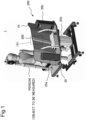
- Fig. 1 is an overhead view of a three-dimensional shape measuring system 1 according to the first present example embodiment when viewed from one side.
- the three-dimensional shape measuring system 1 includes a right photographing unit 20a, a left photographing unit 20b, a base 30, and a center unit 300.
- Fig. 2 is an overhead view of the three-dimensional shape measuring system 1 according to the first present example embodiment when viewed from the other side.
- the three-dimensional shape measuring system 1 further includes a chair 100, a coupling member 150, a stand 250, and a shield plate 10.
- the shield plate 10, the right photographing unit 20a, the left photographing unit 20b, the base 30, and the center unit 300 constitute a photographing apparatus 200 according to the first present example embodiment. The configuration of the photographing apparatus 200 will be described later.
- the three-dimensional shape measuring system 1 may further include an image analysis apparatus 500 described in the fifth example embodiment or an image analysis apparatus 600, 600' described in the sixth example embodiment.
- image data acquired by the right photographing unit 20a and the left photographing unit 20b of the photographing apparatus 200 photographing an object to be measured is transmitted to the image analysis apparatus 500, 600 or 600' via a wired or wireless network.
- the chair 100 includes a headrest that supports the position of the head of the person.
- the headrest fixes the position of the head of the person to be measured.
- the three-dimensional shape measuring system 1 may include a member that supports or fixes the living creature or the obj ect instead of the chair 100.
- a person, a living creature other than a person, and an inanimate being are collectively referred to simply as an "object".
- the shield plate 10 is provided with a plurality of openings.
- the three openings LO1 to LO3 are provided in front of the right photographing unit 20a.
- One opening LO4 is provided at the front of the center unit 300 illustrated in Fig. 1 .
- three openings related to the openings LO1 to LO3 are provided in the shield plate 10 in front of the left photographing unit 20b illustrated in Fig. 1 .
- the coupling member 150 couples the chair 100 and the stand 250.
- the distance between the chair 100 and the stand 250 is maintained constant by the coupling member 150.
- the constant distance is appropriately determined, for example, according to how finely a user desires to obtain an image and according to the focal distance of a camera 22 ( Fig. 11 ) included in the photographing apparatus 200.
- the photographing apparatus 200 is placed on the stand 250.
- the base 30 of the photographing apparatus 200 is connected to the stand 250.
- the shape of the jaw of the face of the person is useful information for identifying the person.
- the jaw portion may not be shown in the image data.
- the height of stand 250 is set in such a way that the camera 22 of each of the right photographing unit 20a and the right photographing unit 20b photographs the head of the person slightly upward. In this way, the camera 22 can photograph up to the jaw of the face of the person.
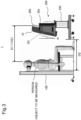
- Fig. 3 is a side view of the three-dimensional shape measuring system 1 according to the first present example embodiment.
- the D2 represents a distance from the backrest of the chair 100 to the leg of the stand 250
- the D1 represents a distance from the head of the person to the upper end of the shield plate 10.
- the D1 is defined by the above-described coupling member 150.
- the offset of the upper end with respect to the lower end of the shield plate 10 may be increased by increasing the inclination of the shield plate 10.
- the distance D1 may be determined in such a way that even when the person extends his/her arm forward, the hand does not reach the upper end of the shield plate 10.
- the inclination of the shield plate 10 can be increased within a range in which the upper end of the shield plate 10 does not contact the photographing unit 20a (20b) behind the shield plate 10.
- Fig. 4 is a perspective view of the photographing apparatus 200 according to the first present example embodiment. As illustrated in Fig. 4 , the photographing apparatus 200 includes the shield plate 10, the right photographing unit 20a, the left photographing unit 20b, the base 30, the stand 250, and the center unit 300.
- the shield plate 10 prevents a person from coming into contact with the right photographing unit 20a, the left photographing unit 20b, or the center unit 300 of the photographing apparatus 200. This is because, when an external force is applied to the right photographing unit 20a, the left photographing unit 20b, or the center unit 300, there is a possibility that these positions are displaced or the camera 22, 310 or the like is damaged.
- the shield plate 10 is desirably formed of a material having low reflectance.
- the shield plate 10 is made of translucent acrylic. Since the reflectance of the shield plate 10 increases as the incident angle of light from the ceiling increases, the angle R ( Fig. 3 ) of the inclination of the shield plate 10 with respect to the vertical direction (corresponding to the vertical direction in Fig. 3 ) is preferably 10 degrees or less.
- the surface of the shield plate 10 may be processed.
- the surface of the shield plate 10 may be painted matte, or may be provided with an uneven structure in such a way as to diffuse light.
- Fig. 5 is an enlarged view of a portion in a frame of a broken line denoted by reference sign (A) in Fig. 1 .
- Fig. 5 is a view illustrating a cross section of a portion of the center unit 300.
- the center unit 300 includes a camera 310 and a light source 320.
- the shield plate 10 is disposed on the front sides of the camera 310 and the light source 320.
- the opening LO4 of the shield plate 10 described above is provided at a position of the shield plate 10 related to the camera lens of the camera 310.
- the camera 310 can photograph the head of the person through the opening LO4.
- the shield plate 10 is also provided with an opening for passing light from the light source 320 on the front side of the light source 320.
- Fig. 2 does not illustrate this opening.
- the light source 320 is, for example, a light emitting diode (LED).
- the camera 310 is used by the user to confirm the position of the head of the person.
- the light source 320 is a so-called pilotlamp that indicates that the photographing apparatus 200 is energized (turned on), and can be used for adjusting the orientation of the head when a person seated on the chair 100 looking at the light source 320.
- the camera 310 captures an image of the head of a person, and the photographing apparatus 200 displays the image acquired by the camera 310 on a display (not illustrated) in real time.
- the user checks the position of the head of the person by viewing the image displayed on the display. Then, the user performs adjustment in such a way that the head of the person falls within a predetermined position.
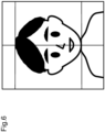
- Fig. 6 illustrates an example of an image displayed on a display (not illustrated) by the photographing apparatus 200.
- three lines are illustrated.
- the two lines in the lateral direction indicate the targets of the top and jaw positions of the person.
- One line in the longitudinal direction indicates the target of the position of the center line passing through the nose and mouth of the person.
- the photographing apparatus 200 may display the image illustrated in Fig. 6 on a display disposed at a position where a person can visually recognize the screen while facing forward, such as on or near the shield plate 10. As a result, the person can appropriately adjust the position and the orientation of the face while checking his/her face displayed on the display.
- the shield plate 10 and the center unit 300 are optional. That is, the photographing apparatus 200 may not include one or both of the shield plate 10 and the center unit 300. For example, in a case where it is unlikely that a person comes into contact with the right photographing unit 20a and the left photographing unit 20b, the photographing apparatus 200 may not include the shield plate 10. In a case where it is not necessary to position the head of the person, the photographing apparatus 200 may not include the center unit 300. A case where the photographing apparatus 200 does not include both the shield plate 10 and the center unit 300 will be described in the second example embodiment.
- Fig. 7 is an enlarged view of a portion in a frame of a broken line denoted by reference sign (B) in Fig. 3 .
- Fig. 7 is a view illustrating removal of the right photographing unit 20a from the base 30.
- the left photographing unit 20b also has a structure equivalent to that of the right photographing unit 20a described below.
- the base 30 is provided with a plurality of pins.
- the bottom face of the right photographing unit 20a is provided with two recesses or holes in a positional relationship related to the first pin and the second pin.
- the first pin and the second pin are fitted into recesses or holes provided in the bottom face of the right photographing unit 20a, whereby the right photographing unit 20a is attached to the base 30.
- the first pin and the second pin are used to position the right photographing unit 20a on the base 30.
- the position of the camera 22 included in the right photographing unit 20a is also determined.
- the housing of the right photographing unit 20a includes a handle 40 used by the user to carry the right photographing unit 20a.
- the user can remove the right photographing unit 20a from the base 30 by lifting the right photographing unit 20a obliquely rearward (arrow in Fig. 7 ).
- the user can attach the right photographing unit 20a to the base 30 by bringing the right photographing unit 20a close to the base 30 in such a way that the recesses or holes provided in the bottom face of the right photographing unit 20a are fitted to the first pin and the second pin of the base 30.
- the relationship between the left photographing unit 20b and the base 30 is the same as the relationship between the right photographing unit 20a and the base 30, and the left photographing unit 20b can be removed from and attached to the base 30 in a similar manner.
- the right photographing unit 20a and the left photographing unit 20b can be detached from the base 30 or attached to the base 30 independently of each other. Therefore, when the camera 22 ( Fig. 11 ) of the right photographing unit 20a (or the left photographing unit 20b) fails, the user can remove only the right photographing unit 20a (or the left photographing unit 20b) including the failed camera 22 from the base 30.
- This configuration is advantageous, compared with a configuration in which a plurality of cameras is integrated into one photographing unit.
- the photographing apparatus 200 in a case where it is necessary to readjust the alignment of the camera 22 of the right photographing unit 20a (or the left photographing unit 20b), only the right photographing unit 20a (or the left photographing unit 20b) is removed from the base 30, and the alignment of the camera 22 is allowedto be adjusted. That is, in the photographing apparatus 200 according to the first present example embodiment, the plurality of photographing units (20a, 20b) is allowed to adjust the alignment of the camera 22 independently of each other.
- a three-dimensional shape measuring system 1' which is a modification of the three-dimensional shape measuring system 1 according to the first example embodiment, will be described with reference to Fig. 8 .
- the D1 represents a distance from the head of the person to the upper end of the shield plate 10.
- the D2 represents a distance from the backrest of a chair 100' to the leg of the stand 250.
- the shield plate 10 is substantially parallel to the axial direction of the stand 250.
- the three-dimensional shape measuring system 1' according to the present modification is different from the three-dimensional shape measuring system 1 according to the first example embodiment.
- the three-dimensional shape measuring system 1 In the three-dimensional shape measuring system 1 according to the first example embodiment, D1 > D2. This means that the space in front of the person to be measured is wider at a position close to the face than at the feet of the person. Therefore, there is an advantage that the less oppressive feeling given to the person.
- An advantage of the present modification is that the user can easily perform maintenance work. In the configuration of the present modification, since the shield plate 10 is not inclined rearward, the user can lift the right photographing unit 20a and the left photographing unit 20b directly upward without paying much attention to contact with the shield plate 10.
- the second example embodiment will be described with reference to Figs. 9 to 11 .
- an example of the photographing apparatus 200 applied to the three-dimensional shape measuring system 1 according to the first example embodiment will be described.
- Fig. 9 is a diagram illustrating a configuration of the photographing apparatus 200 according to the second present example embodiment.
- the photographing apparatus 200 according to the second present example embodiment includes the right photographing unit 20a, the left photographing unit 20b, and the base 30.
- the photographing apparatus 200 according to the second present example embodiment is different from the photographing apparatus 200 according to the first example embodiment in that the center unit 300 is not provided.
- right photographing unit 20a is positioned on the base 30 by two pins provided on the base 30. That is, the bottom face of the right photographing unit 20a is provided with two recesses or holes indicated by reference signs F1 and F2, and the recesses or holes F1 and F2 are fitted with the first pin and the second pin, respectively, so that the right photographing unit 20a does not move in the in-plane direction of the base 30.
- the left photographing unit 20b is positioned on the base 30 by the other two pins provided on the base 30.
- the right photographing unit 20a is positioned by a set of two pins instead of one pin.
- a set of two pins determine the position and orientation of the right photographing unit 20a. That is, the positions of the two pins define the position of the right photographing unit 20a on the face of the base 30, and the direction of the straight line passing through the two pins defines the orientation of the right photographing unit 20a on the face of the base 30.
- the left photographing unit 20b is oriented by a set of the other two pins provided on the base 30. The user is only required to align the two recesses or holes provided in the bottom face of the right photographing unit 20a or the left photographing unit 20b with a set of the other two pins provided in the base 30 and fit them. Therefore, the user does not have to adjust the orientations of the right photographing unit 20a and the left photographing unit 20b.
- the movement of the right photographing unit 20a and the left photographing unit 20b in the upward direction is not limited by the pins. Therefore, it is easy to remove the right photographing unit 20a and the left photographing unit 20b from the base 30. The user is only required to lift the right photographing unit 20a and the left photographing unit 20b obliquely backward.
- the photographing unit 20a (20b) will be described with reference to Figs. 10 to 11 .
- the "photographing unit 20a (20b)" means the right photographing unit 20a or the left photographing unit 20b.
- a configuration common to the right photographing unit 20a or the left photographing unit 20b will be described as the "photographing unit 20a (20b)".
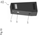
- Fig. 10 is an external view of the photographing unit 20a (20b). As illustrated in Fig. 10 , the housing of the photographing unit 20a (20b) has three openings so1 to so3.
- Fig. 11 is a cross-sectional view of the photographing unit 20a (20b) illustrated in Fig. 10 .
- a main body 21 of the photographing unit 20a (20b) is stored in a housing of the photographing unit 20a (20b).
- the camera 22, a light source 23, and a projector 24 are attached to the main body 21.
- the positions of the openings so1 to so3 of the housing are related to the positions of the camera 22, the light source 23, and the projector 24.
- the positions of the three openings so1 to so3 of the photographing unit 20a (20b) are related to the positions of the openings LO1 to LO3 of the shield plate 10 described in the first example embodiment. That is, in a case where the photographing unit 20a (20b) according to the second present example embodiment is applied to the three-dimensional shape measuring system 1 according to the first example embodiment, the openings so1 to so3 of the right photographing unit 20a overlap the openings LO1 to LO3 of the shield plate 10 illustrated in Fig. 1 .
- the camera 22 of the photographing unit 20a (20b) can photograph the head of the person through the opening so1 of the housing and the opening LO1 of the shield plate.
- the light source 23 of the photographing unit 20a (20b) irradiates the head of the person through the opening so2 of the housing and the opening LO2 of the shield plate.
- the projector 24 of the photographing unit 20a (20b) projects a light pattern onto the head of the person through the opening so3 of the housing and the opening LO2 of the shield plate.
- the object By irradiating the obj ectwith light from the light source 23, the object can be clearly photographed even in a dark environment. Specifically, an image with small noise (S/N ratio) can be acquired by adapting the wavelength range of the light to be emitted to the wavelength range of the spectrum to be captured.
- S/N ratio small noise
- the pattern of light projected onto the obj ect by the projector 24 changes to a shape along the surface of the obj ect on the surface of the object. Therefore, it is possible to calculate the three-dimensional shape of the object based on the changed shape.
- a technique related to the technique disclosedin PTL 1 can be applied.
- the photographing unit 20a (20b) may not include one of the light source 23 and the projector 24 or may include neither of them.
- the xyz coordinate system illustrated in Fig. 11 is equivalent to the xyz coordinate system illustrated in Fig. 12 described below.
- positions and orientations of a plurality of cameras are adjusted in advance and then fixed to a support member.
- An external force such as an impact may cause the position or orientation of any of the cameras to deviate or cause a failure in any of the cameras.
- the photographing unit 20a and the photographing unit 20b are allowed to adjust the alignment of the camera 22 independently of each other.
- the photographing unit 20a (20b) includes the main body 21 connected to the base 30, the camera 22 is fixed to the main body 21, and the orientation of the camera 22 is adjusted with reference to the base 30.
- the plurality of photographing units 20a and 20b Since the plurality of photographing units 20a and 20b is both attached to the base 30, it can be said that the plurality of photographing units 20a and 20b share a coordinate system. With the base 30 as a reference, it is possible to save time and effort to determine a common coordinate system before the orientations of the cameras 22 of the plurality of photographing units 20a and 20b are independently adjusted.
- the photographing unit 20a (20b) of the photographing apparatus 200 may include one or both of the structures in which alignment adjustment described in the third example embodiment and the fourth example embodiment is implement.
- the third example embodiment will be described with reference to Figs. 12 to 16 .
- a specific example of alignment adjustment described in the second example embodiment will be described.
- a fitting means to be fitted to the base 30 is attached to the main body 21 of the photographing unit 20a (20b), and there is a clearance at a position of the main body 21 to which the fitting means can be attached.
- the orientation of the photographing unit 20a (20b) is allowedto be adjusted on the base 30 by changing the position of the fitting means attached to the main body 21.
- the photographing unit 20a (20b) When the fitting means attached to the main body 21 is fitted to the base 30, the photographing unit 20a (20b) is positioned. Since there is a clearance at the position of the main body 21 to which the fitting means can be attached, the orientation of the photographing unit 20a (20b) is allowedto be adjusted by changing the position of the fitting means within this clearance. Specifically, the position of the fitting means is allowed to be adjusted in such a way as to change the orientation of the camera 22 fixed to the main body 21 of the photographing unit 20a (20b). That is, the orientation of the camera 22 is allowed to be adjusted by adjusting the position of the fitting means.
- Fig. 12 illustrates an external appearance of the main body 21 of the photographing unit 20a (20b) illustrated in Fig. 11 . However, in Fig. 12 , the direction of the y axis is reversed from that in Fig. 11 . Fig. 12 also illustrates a fitting portion 25 to be attached to the bottom face of the main body 21.
- the fitting portion 25 is an example of the fitting means described above.
- Fig. 13 is a view of a portion in a frame of a broken line denoted by reference sign (C) in Fig. 12 when viewed from a lower side (bottom face side) of the main body 21.
- the bottom face of the main body 21 has an elliptical recess D1.
- Three holes G0 to G2 are disposed side by side in the recess D1.
- the middle hole G0 is circular and large, and the two holes G1 and G2 on both sides thereof are narrow and small.
- the shape and arrangement of these three holes G0 to G2 are not critical.
- the second pin of a set of two pins of the base 30 illustrated in Fig. 9 is inserted into the middle hole G0.
- the diameter of the middle hole G0 is larger than the thickness of the second pin. Therefore, when the second pin is inserted into the middle hole G0, the second pin can move in the hole G0.
- the shape and arrangement of the three holes G0-G2 of the main body 21 illustrated in Fig. 13 is merely an example. These holes G0 to G2 may have any shape and arrangement. Further, as will be described later, the holes G1 and G2 are provided as screw holes for inserting screws into the fitting portion 25. On the other hand, when the fitting portion 25 is attached to the main body 21 by means other than screws, the holes G1 and G2 are unnecessary.
- Fig. 14 is a view of the main body 21 when viewed from the bottom face side.
- the fitting portion 25 is inserted into the recessD1 ( Fig. 13 ) providedin the bottom face of the main body 21.
- the fitting portion 25 has a shape in which a half-moon shaped cut-out D0 is formed on a rectangular plate having round corners.
- the half-moon shaped cut-out D0 and the hole G0 in the bottom face of the main body 21 partially overlap each other, so that a function related to the depression or the hole F2 ( Fig. 9 ) of the second example embodiment is implemented.
- the main body 21 is positioned by fitting the second pin of the base 30 to the hole formed by the cut-out D0 and the hole G0.
- the position of the hole G0 at the center of the bottom face of the main body 21 is related to the position of the cut-out D0 of the fitting portion 25.
- the fitting portion 25 is slightly smaller in the x-axis direction (left-right direction) than the recess D1 in the bottom face of the main body 21 into which the fitting portion 25 is inserted. Therefore, the fitting portion 25 can move in the positive and negative directions of the x axis in the recessD1.
- the fitting portion 25 can be attached anywhere in the recess D1 by being fixed to the main body 21 by a method described later.
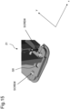
- Fig. 15 is a view of a portion in a frame of a broken line denoted by reference sign (C) in Fig. 12 when viewed from the upper side of the main body 21.
- C a broken line denoted by reference sign
- Fig. 15 screws are passed through two holes on both sides of the hole G0 in the bottom face of the main body 21. The screw is inserted into the fitting portion 25 attached to the bottom face of the main body 21. However, before the alignment adjustment described later is performed, the screw is temporarily fixed, and the fitting portion 25 can freely move in the recess D1 of the bottom face of the main body 21.
- a target (also referred to as an alignment mark) is disposed in front of the main body 21 (in the positive direction of the y axis).
- a set of two pins A and B is provided on the base for alignment adjustment. These pins A and B simulate the first pin and the second pin ( Fig. 3 ) of the base 30. That is, the shape and size of the pin A are equal to the shape and size of the first pin of the base 30.
- the shape and size of the pin B are equal to the shape and size of the second pin of the base 30.
- the distance between the pin A and the pin B is equal to the distance between the first pin and the second pin.
- the user first fits the bottom face of the main body 21 to the pins A and B.
- the pin A is fitted into a recess or hole F1 ( Fig. 11 ) provided in the bottom face of the main body 21, and the pin B is fitted into the fitting portion 25 illustrated in Fig. 14 .
- the user rotates the main body 21 in the positive or negative directions of the x axis with the pin A as a fulcrum and the y axis as a central axis in such a way that the optical axis of the camera lens of the camera 22 matches the center of the target.
- the fitting portion 25 attached to the bottom face of the main body 21 moves in a direction opposite to a direction in which the user rotates the main body in the recess D1 of the bottom face of the main body 21.
- the user tightens the screw ( Fig. 15 ) inserted into the fitting portion 25 through the main body 21 to fix the position of the fitting portion 25. In this way, the adjustment of the alignment in the left-right direction is completed.
- the central axis of rotation of the main body 21 preferably passes through the pin A and the camera 22. That is, the pin A, which is a fulcrum of rotation, is preferably installed directly below the camera 22.
- the pin A which is a fulcrum of rotation
- the fourth example embodiment will be described with reference to Figs. 17 to 19 .
- a specific example of alignment adjustment described in the second example embodiment will be described.
- the main body 21 of the photographing unit 20a (20b) is provided with a plurality of screw holes
- the camera 22 is fixed to the main body 21 by inserting screws (tips of bolts) into the camera 22 through the plurality of screw holes, and the diameter of at least one screw hole is larger than the thickness of the screw passed through the screw hole.
- the orientation of the camera 22 is allowed to be adjusted by moving the screws within the range of the diameter of the screw holes.
- the "photographing unit 20a (20b)" means the right photographing unit 20a or the left photographing unit 20b.
- a diameter of at least one of the plurality of screw holes provided in the main body 21 of the photographing unit 20a (20b) is larger than a thickness of the screw. This means that the screw can be freely moved in the screw hole.
- the orientation of the camera 22 in the z-axis direction that is, the vertical direction when the positive direction of the y-axis is the front direction
- the alignment of the camera 22 is allowedto be adjusted by moving the position of the screw. After positioning the screw, the screw is tightly fastened, so that the movement of the screw can be stopped by friction between the head of the screw and the main body.
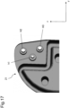
- Fig. 17 is a view of a portion in a frame of a broken line denoted by reference sign (D) in Fig. 12 when viewed from the right side (negative direction of the x axis) of the main body 21.
- the main body 21 is provided with three screw holes.
- the diameter of a first screw hole h1 is equal to the thickness of the screw passing therethrough.
- the diameters of a second screw hole H2 and a third screw hole H3 are larger than the thickness of the screw passing therethrough.
- the second screw hole H2 and the third screw hole H3 are drawn larger than the first screw hole h1. This is because it is assumed as an example that screws having the same thickness pass through the first screw hole h1, the second screw hole H2, and the third screw hole H3.
- the second screw hole H2 and the third screw hole H3 are not necessarily larger than the first screw hole h1.
- the thickness of the screw passing through the second screw hole H2 and the third screw hole H3 may be smaller than the thickness of the screw passing through the first screw hole h1.
- a size relationship between the first screw hole h1, and the second screw hole H2 and the third screw hole H3 is not limited.
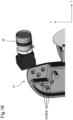
- tips of three screws protruding from the three screw holes are inserted into the related three screw holes of the camera 22 using screws from one sides of the first screw hole h1 and the second to third screw holes H2 and H3.
- the thickness of the screw passing through the first screw hole h1 is equal to the thicknesses of the screws passing through the second screw hole H2 and the third screw hole H3.
- the head of the screw is sufficiently large so as not to pass through the first screw hole h1 and the second screw hole H2 and the third screw hole H3.
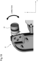
- Fig. 19 illustrates a state in which the camera 22 is temporarily fixed by three screws. Since the diameter of each of the second screw hole H2 and the third screw hole H3 is larger than the thickness of the screw, the camera 22 can move in the z-axis direction around the first screw hole h1, that is, in the vertical direction when the positive direction of the y-axis is the front direction.
- the user performs alignment adjustment by a procedure illustrated in Fig. 16 . That is, after the optical axis of the camera lens of the camera 22 matches the center of the target in the vertical direction, the user fixes the position of the camera 22 by tightening three screws ( Fig. 19 ) inserted into the camera 22. In this way, the alignment adjustment is completed.
- the fifth example embodiment will be described with reference to Figs. 20 to 21 .
- the image analysis apparatus 500 that acquires and analyzes a plurality of pieces of image data from the right photographing unit 20a and the left photographing unit 20b of the photographing apparatus 200 described in the first to fourth example embodiments will be described.
- the image analysis apparatus 500 according to the fifth present example embodiment may be included in the three-dimensional shape measuring system 1 ( Fig. 1 ) described in the first example embodiment. That is, the image analysis apparatus 500 may be a component of the three-dimensional shape measuring system 1.
- Fig. 20 is a block diagram illustrating a configuration of the image analysis apparatus 500 according to the fifth present example embodiment. As illustrated in Fig. 20 , the image analysis apparatus 500 includes an acquisition unit 510 and a calculation unit 520.
- the acquisition unit 510 acquires, from the photographing apparatus 200 ( Fig. 1 or 9 ), a plurality of pieces of image data when a plurality of photographing units including the right photographing unit 20a and the left photographing unit 20b photographs the same object from different directions.
- the acquisition unit 510 is an example of the acquisition means.
- the acquisitionunit 510 connects communication with the photographing apparatus 200 using a communication unit (not illustrated) (installed on the back face of the base 30).
- the plurality of pieces of image data acquired by the right photographing unit 20a and the left photographing unit 20b is transmitted from the photographing apparatus 200 via the network.
- the acquisition unit 510 receives a plurality of pieces of image data transmitted from the photographing apparatus 200.
- the acquisitionunit 510 outputs the plurality of pieces of acquired image data to the calculation unit 520.
- the calculation unit 520 calculates at least part of the three-dimensional shape of the obj ect (in an example, the head of the person) based on the plurality of pieces of image data.
- the calculation unit 520 is an example of the calculation means.
- the calculation unit 520 calculates the distance from the reference position (for example, the midpoint between the right photographing unit 20a and the left photographing unit 20b) to the measurement point based on the parallax between the measurement point on the image data acquired by the right photographing unit 20a and the same measurement point on the image data acquired by the left photographing unit 20b.
- the calculation unit 520 calculates at leastpart of the three-dimensional shape of the object by mapping a plurality of measurement points on the obj ect appearing in the image data and calculating the distance to each measurement point by the above-described method.
- the calculationunit 520 may output the calculation result of the three-dimensional shape of the object to a display or the like.
- the calculation result of the three-dimensional shape of the object includes data of the 3D model regarding changes in the appearance of the obj ect when the obj ect is viewed from various directions.
- the calculation unit 520 may store the calculation result of the three-dimensional shape of the obj ect in a storage device (not illustrated).
- the calculation unit 520 can calculate the three-dimensional shape of the object by a three-dimensional shape analysis method using the light pattern projected by the projector24. (one example; 3D model image)
- Fig. 21 illustrates an example of display based on the calculation result of the calculation unit 520.
- the object to be measured is the head of the person.
- the head of the person (that is, the objectto be measured) is reproducedas an image of a 3D model.
- the display illustrated as (a) of Fig. 21 the left side of the head of the person is mainly displayed.
- the display illustrated as (b) of Fig. 21 the right side of the head of the person is mainly displayed.
- the image of the 3D model of the head of the person may be transitionable between the display illustrated as (a) of Fig. 21 and the display illustrated as (b) of Fig. 21 by the input operation of the user.
- the sixth example embodiment will be described with reference to Figs. 22 to 23 .
- an image analysis apparatus 600 that acquires and analyzes a plurality of pieces of image data from the right photographing unit 20a and the left photographing unit 20b of the photographing apparatus 200 described in the first to fourth example embodiments, and an image analysis apparatus 600' as a modification thereof will be described.
- the image analysis apparatus 600 according to the sixth present example embodiment or the image analysis apparatus 600' according to a modification thereof may be included in the three-dimensional shape measuring system 1 ( Fig. 1 ) described in the first example embodiment. That is, the image analysis apparatus 600, 600' may be a component of the three-dimensional shape measuring system 1.
- Fig. 22 is a block diagram illustrating a configuration of the image analysis apparatus 600 according to the sixth present example embodiment. As illustrated in Fig. 22 , the image analysis apparatus 600 further includes a combining unit 630 in addition to the acquisition unit 510 and the calculation unit 520. The image analysis apparatus 600 according to the sixth present example embodiment is different from the image analysis apparatus 500 according to the fifth example embodiment in that it further includes the combining unit 630.
- the combining unit 630 combines the plurality of pieces of image data to generate image data indicating at least part of the three-dimensional shape of the object.
- the combining unit 630 is an example of the combining means.
- a plurality of pieces of image data can be obtained.
- image data indicating at least part of the three-dimensional shape of the object can be obtained.
- the obj ect can be accurately identified regardless of the orientation of the obj ect.
- the combining unit 630 uses a known image technology such as integral photography.
- the combining unit 630 receives, from the acquisition unit 5 10, a plurality of pieces of image data obtained by photographing the same obj ect from different directions and acquires, from the calculation unit 520, data of the 3D model ( Fig. 21 ) included in the calculation result of the three-dimensional shape of the object. Then, the combining unit 630 determines a pixel value related to each point of the 3D model of the obj ect based on the plurality of pieces of image data by the ray tracing method. In this way, when the pixel value at each point of the 3D model is determined, the combining unit 630 can obtain image data (sometimes referred to as combined image data) indicating at least part of the three-dimensional shape of the object.
- image data sometimes referred to as combined image data
- the combining unit 630 may output the combined image data to a display or the like. Alternatively, the combining unit 630 may store the combined image data in a storage device (not illustrated).
- An advantage of the combined image data is that the user can see various sides of the object to be measured (for example, the head of a person). For example, the left side of the head of the person is photographed by the right photographing unit 20a, and the right side of the head of the person is photographed by the left photographing unit 20b, whereby image data in which the shape of the left ear of the person can be known and image data in which the shape of the right ear of the person can be known are obtained. By combining these pieces of image data, combined image data in which the shapes of both ears can be viewed is obtained.
- Fig. 23 is a block diagram illustrating a configuration of an image analysis apparatus 600' that is a modification of the image analysis apparatus 600 according to the sixth example embodiment. As illustrated in Fig. 23 , the image analysis apparatus 600' further includes a correction unit 640 in additionto the acquisition unit 510, the calculation unit 520, and the combining unit 630.
- the image analysis apparatus 600' according to the present modification is different from the image analysis apparatus 600 according to the sixth example embodiment in that it further includes the correction unit 640.
- the correction unit 640 corrects an inconsistency between the plurality of pieces of image data based on a deviation in adjustment of the orientation of the camera 22.
- the correctionunit 640 is an example of the correction means.
- the combining unit 630 (an example of the combining means) combines a plurality of pieces of corrected image data.
- the position and orientation of the camera 22 are determined by adjustment of the alignment, but there may be a deviation from the reference.
- the correction unit 640 corrects the influence of the deviation by calibration, thereby obtaining image data in a case where the camera 22 is at the reference position and direction.
- the combining unit 630 can obtain image data with less inconsistency than that in a case where the image data before correction is combined. That is, image data indicating the accurate three-dimensional shape of the obj ect can be obtained.
- the correction unit 640 assumes that the alignment adjustment ( Fig. 16 ) is accurate, and identifies a region viewed in common between the field of view of the camera 22 included in the right photographing unit 20a and the field of view of the camera 22 included in the left photographing unit 20b. Then, the correction unit 640 compares the pixel values in the identified region among the plurality of pieces of image data obtained by photographing the same obj ect from different directions, and calculates the size of the region in which the pixel values do not match with each other.
- the correctionunit 640 searches for a combination of parameters with which the size of the region where the pixel values do not match is the smallest, with the orientation of the camera 22 included in the right photographing unit 20a as a first parameter and the orientation of the camera 22 included in the left photographing unit 20b as a second parameter.
- the correction unit 640 calculates the actual orientation for each of the camera 22 included in the right photographing unit 20a and the camera 22 included in the left photographing unit 20b based on the first parameter and the second parameter identified in the above-described procedure. Then, the correction unit 640 calibrates the image data acquired by the right photographing unit 20a based on the calculation result of the orientation of the camera 22 included in the right photographing unit 20a. The correction unit 640 calibrates the image data acquired by the right photographing unit 20b based on the calculation result of the orientation of the camera 22 included in the right photographing unit 20b.
- the correction unit 640 may present how much the actual orientation of the camera 22 deviates from the reference by any means for each of the camera 22 included in the right photographing unit 20a and the camera 22 included in the left photographing unit 20b, or may request the user to adjust the alignment of the camera 22.
- the correction unit 640 outputs the plurality of pieces of image data corrected as described above to the combining unit 630.
- the combining unit 630 combines the plurality of pieces of image data corrected by the correction unit 640 instead of the plurality of pieces of image data acquired by the acquisition unit 510.
- Fig. 24 is a block diagram illustrating an example of a hardware configuration of the information processing device 900.
- the information processing device 900 includes the following configuration as an example.
- the above-described processor 901 may be a central processing unit (CPU).
- the processor 901 may be a graphics processing unit (GPU), a field-programmable gate array (FPGA), a demand-side platform (DSP), or an application specific integrated circuit (ASIC).
- GPU graphics processing unit
- FPGA field-programmable gate array
- DSP demand-side platform
- ASIC application specific integrated circuit
- the components of the image analysis apparatus 500, 600, 600' described in the fifth to sixth example embodiments are implemented by the CPU 901 reading and executing a program 904 that implements these functions.
- the program 904 for achieving the function of each component is stored in the storage device 905 or the ROM 902 in advance, for example, and the CPU 901 loads the program into the RAM 903 and executes the program as necessary.
- the program 904 may be supplied to the CPU 901 via the communication network 909, or may be stored in advance in the recording medium 906, and the drive device 907 may read the program and supply the program to the CPU 901.
- a photographing apparatus including
- the photographing apparatus according to any one of Supplementary Notes 1 to 6, wherein the plurality of photographing units includes a set of two photographing units that photographs a same object from different directions.
- the photographing apparatus according to any one of Supplementary Notes 1 to 7, wherein the plurality of photographing units is both attached to the base.
- the photographing unit according to Supplementary Note 9 further including a projector that projects a pattern by light onto an obj ect to be photographed by the photographing unit.
- An image analysis apparatus including
- the image analysis apparatus further including a combining means configured to generate image data indicating a three-dimensional shape of the object by combining the plurality of pieces of image data.
- the present disclosure can be used in a photographing apparatus including a plurality of cameras and capable of photographing an object from different directions.
Landscapes
- Engineering & Computer Science (AREA)
- Physics & Mathematics (AREA)
- General Physics & Mathematics (AREA)
- Multimedia (AREA)
- Signal Processing (AREA)
- Computer Vision & Pattern Recognition (AREA)
- Theoretical Computer Science (AREA)
- Length Measuring Devices By Optical Means (AREA)
- Accessories Of Cameras (AREA)
- Stereoscopic And Panoramic Photography (AREA)
Abstract
Description
- The present disclosure relates to a photographing apparatus, a photographing unit, an image analysis apparatus, and a three-dimensional shape measuring system, and more particularly, to a photographing apparatus that photographs the same object from a plurality of different directions.
- In the police, medical fields, beauty industries, and the like, there is a need to generate an image of a three-dimensional shape of a human head. Therefore, a three-dimensional shape measuring system has been developed that uses a plurality of cameras to photograph an obj ect from a plurality of different directions and analyzes a plurality of pieces of obtained image data to measure a three-dimensional shape of the object with high accuracy (PTL 1). A related photographing apparatus photographs an obj ect from a plurality of different directions. A related image analysis apparatus measures a three-dimensional shape of an object based on a plurality of pieces of image data obtained by a related photographing apparatus.
- Then, the related image analysis apparatus generates and outputs an image of the three-dimensional shape of the obj ect based on the measurement result. Even in a case where a moving obj ect such as a human is an objectto be measured, a plurality of cameras simultaneously or substantially simultaneously photographs the object, so that the photographing can be completed at high speed, and the three-dimensional shape of the obj ect can be measured with high accuracy.
- [PTL 1]
JP 2005-106491 A - This disclosure aims to improve the techniques disclosed in the aforementioned prior art documents.
- A photographing apparatus according to an aspect of the present disclosure includes a plurality of photographing units each of which includes a camera, and a base to which the plurality of photographing units is attached, wherein the plurality of photographing units is allowed to adjust alignment of the respective cameras independently of each other.
- An image analysis apparatus according to an aspect of the present disclosure includes an acquisition means configured to acquire, from the photographing apparatus, a plurality of pieces of image data obtained by the plurality of photographing units photographing a same obj ect from different directions, and a calculation means configured to calculate at least part of a three-dimensional shape of the object based on the plurality of pieces of image data.
- A three-dimensional shape measuring system according to an aspect of the present disclosure includes the photographing apparatus and the image analysis apparatus.
-
-
Fig. 1 is an overhead view of a three-dimensional shape measuring system according to the first example embodiment when viewed from one side. -
Fig. 2 is a bird's-eye view of the three-dimensional shape measuring system according to the first example embodiment when viewed from another side. -
Fig. 3 is a side view of the three-dimensional shape measuring system according to the first example embodiment. -
Fig. 4 is a perspective view illustrating an appearance of the photographing apparatus according to the first example embodiment. -
Fig. 5 is an enlarged view of a main part of the three-dimensional shape measuring system illustrated inFig. 1 , and is a view illustrating a cross section of a center unit included in the photographing apparatus according to the first example embodiment. -
Fig. 6 is a diagram illustrating an example of an image displayed on a display by the photographing apparatus according to the first example embodiment. -
Fig. 7 is an enlarged view of a main part of the three-dimensional shape measuring system illustrated inFig. 5 , and is a view for explaining a method of detaching the photographing unit included in the photographing apparatus according to the first example embodiment. -
Fig. 8 is a diagram illustrating a modification of the three-dimensional shape measuring system according to the first example embodiment. -
Fig. 9 is a diagram illustrating a configuration of a photographing apparatus according to the second example embodiment. -
Fig. 10 is a view illustrating an appearance of a photographing unit included in the photographing apparatus according to the second example embodiment. -
Fig. 11 is a cross-sectional view of the photographing unit illustrated inFig. 10 . -
Fig. 12 is a perspective view of a main body mounted in a housing of a photographing unit according to the third example embodiment. -
Fig. 13 is a first view illustrating part of the back side of the bottom face of the main body of the photographing unit according to the third example embodiment. -
Fig. 14 is a second view illustrating part of the back side of the bottom face of the main body of the photographing unit according to the third example embodiment, and is a view illustrating an example of the fitting portion. -
Fig. 15 is a view illustrating part of the front side of the bottom face of the main body of the photographing unit according to the third example embodiment, and is a view illustrating a state in which the fitting portion is attached to the back side of the bottom face of the main body of the photographing unit. -
Fig. 16 is a diagram illustrating adjustment of alignment in the left-right direction of the photographing unit according to the third example embodiment. -
Fig. 17 is a first view illustrating a top portion of a main body of a photographing unit according to the fourth example embodiment, and is a view illustrating an example of a plurality of holes provided at the top portion of the main body. -
Fig. 18 is a second view illustrating the top portion of the main body of the photographing unit according to the fourth example embodiment, and is a view illustrating a method of attaching the camera to the main body using a screw. -
Fig. 19 is a third view illustrating the top portion of the main body of a photographing unit according to the fourth example embodiment, and is a view for explaining adjustment of alignment in the vertical direction. -
Fig. 20 is a block diagram illustrating a configuration of an image analysis apparatus according to the fifth example embodiment. -
Fig. 21 is a diagram illustrating an example of an image of an obj ect 3D model. -
Fig. 22 is a block diagram illustrating a configuration of an image analysis apparatus according to the sixth example embodiment. -
Fig. 23 is a block diagram illustrating a configuration of an image analysis apparatus according to a modification of the sixth example embodiment. -
Fig. 24 is a diagram illustrating an example of a hardware configuration of the image analysis apparatus according to the example embodiments 5 and 6 or a modification thereof. - The first example embodiment will be described with reference to
Figs. 1 to 7 . -
Fig. 1 is an overhead view of a three-dimensionalshape measuring system 1 according to the first present example embodiment when viewed from one side. As illustrated inFig. 1 , the three-dimensionalshape measuring system 1 includes aright photographing unit 20a, a left photographingunit 20b, abase 30, and acenter unit 300. -
Fig. 2 is an overhead view of the three-dimensionalshape measuring system 1 according to the first present example embodiment when viewed from the other side. As illustrated inFig. 2 , the three-dimensionalshape measuring system 1 further includes achair 100, acoupling member 150, astand 250, and ashield plate 10. Theshield plate 10, the right photographingunit 20a, the left photographingunit 20b, thebase 30, and thecenter unit 300 constitute a photographingapparatus 200 according to the first present example embodiment. The configuration of the photographingapparatus 200 will be described later. - The three-dimensional
shape measuring system 1 may further include animage analysis apparatus 500 described in the fifth example embodiment or animage analysis apparatus 600, 600' described in the sixth example embodiment. In this case, image data acquired by the right photographingunit 20a and the left photographingunit 20b of the photographingapparatus 200 photographing an object to be measured is transmitted to theimage analysis apparatus - A person sits on the
chair 100. Thechair 100 includes a headrest that supports the position of the head of the person. The headrest fixes the position of the head of the person to be measured. In a case where the object to be measured is not a person but a living creature such as a dog or a snake or an obj ect including an inanimate being having a shape, the three-dimensionalshape measuring system 1 may include a member that supports or fixes the living creature or the obj ect instead of thechair 100. Hereinafter, a person, a living creature other than a person, and an inanimate being are collectively referred to simply as an "object". - As illustrated in
Fig. 2 , theshield plate 10 is provided with a plurality of openings. The three openings LO1 to LO3 are provided in front of the right photographingunit 20a. One opening LO4 is provided at the front of thecenter unit 300 illustrated inFig. 1 . InFig. 2 , although hidden by a person, three openings related to the openings LO1 to LO3 are provided in theshield plate 10 in front of the left photographingunit 20b illustrated inFig. 1 . - The
coupling member 150 couples thechair 100 and the stand 250. The distance between thechair 100 and thestand 250 is maintained constant by thecoupling member 150. The constant distance is appropriately determined, for example, according to how finely a user desires to obtain an image and according to the focal distance of a camera 22 (Fig. 11 ) included in the photographingapparatus 200. - The photographing
apparatus 200 is placed on thestand 250. Thebase 30 of the photographingapparatus 200 is connected to thestand 250. The shape of the jaw of the face of the person is useful information for identifying the person. However, in the related technique, since the head of the person is photographed from the front, the jaw portion may not be shown in the image data. On the other hand, in the first present example embodiment, the height ofstand 250 is set in such a way that thecamera 22 of each of theright photographing unit 20a and theright photographing unit 20b photographs the head of the person slightly upward. In this way, thecamera 22 can photograph up to the jaw of the face of the person. -
Fig. 3 is a side view of the three-dimensionalshape measuring system 1 according to the first present example embodiment. InFig. 3 , two distances D1 and D2 are illustrated. The D2 represents a distance from the backrest of thechair 100 to the leg of thestand 250, and the D1 represents a distance from the head of the person to the upper end of theshield plate 10. The D1 is defined by the above-describedcoupling member 150. - In order to further extend the distance D1 from the head of the person to the upper end of the
shield plate 10, the offset of the upper end with respect to the lower end of theshield plate 10 may be increased by increasing the inclination of theshield plate 10. In this way, the space in front of the eyes of the person can be expanded, and the oppressive feeling of the person can be alleviated. The distance D1 may be determined in such a way that even when the person extends his/her arm forward, the hand does not reach the upper end of theshield plate 10. As a result, it is possible to prevent a person from holding the upper end of theshield plate 10 and interfering with imaging by the photographingapparatus 200. The inclination of theshield plate 10 can be increased within a range in which the upper end of theshield plate 10 does not contact the photographingunit 20a (20b) behind theshield plate 10. -
Fig. 4 is a perspective view of the photographingapparatus 200 according to the first present example embodiment. As illustrated inFig. 4 , the photographingapparatus 200 includes theshield plate 10, theright photographing unit 20a, theleft photographing unit 20b, thebase 30, thestand 250, and thecenter unit 300. - The
shield plate 10 prevents a person from coming into contact with theright photographing unit 20a, theleft photographing unit 20b, or thecenter unit 300 of the photographingapparatus 200. This is because, when an external force is applied to theright photographing unit 20a, theleft photographing unit 20b, or thecenter unit 300, there is a possibility that these positions are displaced or thecamera - In order to prevent or suppress the light from the ceiling illumination from being reflected by the
shield plate 10 and illuminating the face of the person, theshield plate 10 is desirably formed of a material having low reflectance. In an example, theshield plate 10 is made of translucent acrylic. Since the reflectance of theshield plate 10 increases as the incident angle of light from the ceiling increases, the angle R (Fig. 3 ) of the inclination of theshield plate 10 with respect to the vertical direction (corresponding to the vertical direction inFig. 3 ) is preferably 10 degrees or less. - Furthermore, in order to further reduce reflection of light by the
shield plate 10, the surface of theshield plate 10 may be processed. For example, the surface of theshield plate 10 may be painted matte, or may be provided with an uneven structure in such a way as to diffuse light. -
Fig. 5 is an enlarged view of a portion in a frame of a broken line denoted by reference sign (A) inFig. 1 .Fig. 5 is a view illustrating a cross section of a portion of thecenter unit 300. - As illustrated in
Fig. 5 , thecenter unit 300 includes acamera 310 and alight source 320. As illustrated inFig. 1 , theshield plate 10 is disposed on the front sides of thecamera 310 and thelight source 320. - The opening LO4 of the
shield plate 10 described above is provided at a position of theshield plate 10 related to the camera lens of thecamera 310. Thecamera 310 can photograph the head of the person through the opening LO4. Theshield plate 10 is also provided with an opening for passing light from thelight source 320 on the front side of thelight source 320. However,Fig. 2 does not illustrate this opening. Thelight source 320 is, for example, a light emitting diode (LED). - The
camera 310 is used by the user to confirm the position of the head of the person. Thelight source 320 is a so-called pilotlamp that indicates that the photographingapparatus 200 is energized (turned on), and can be used for adjusting the orientation of the head when a person seated on thechair 100 looking at thelight source 320. Thecamera 310 captures an image of the head of a person, and the photographingapparatus 200 displays the image acquired by thecamera 310 on a display (not illustrated) in real time. The user checks the position of the head of the person by viewing the image displayed on the display. Then, the user performs adjustment in such a way that the head of the person falls within a predetermined position. -
Fig. 6 illustrates an example of an image displayed on a display (not illustrated) by the photographingapparatus 200. In the image illustrated inFig. 6 , three lines are illustrated. The two lines in the lateral direction indicate the targets of the top and jaw positions of the person. One line in the longitudinal direction indicates the target of the position of the center line passing through the nose and mouth of the person. - Alternatively, the photographing
apparatus 200 may display the image illustrated inFig. 6 on a display disposed at a position where a person can visually recognize the screen while facing forward, such as on or near theshield plate 10. As a result, the person can appropriately adjust the position and the orientation of the face while checking his/her face displayed on the display. - The
shield plate 10 and thecenter unit 300 are optional. That is, the photographingapparatus 200 may not include one or both of theshield plate 10 and thecenter unit 300. For example, in a case where it is unlikely that a person comes into contact with theright photographing unit 20a and theleft photographing unit 20b, the photographingapparatus 200 may not include theshield plate 10. In a case where it is not necessary to position the head of the person, the photographingapparatus 200 may not include thecenter unit 300. A case where the photographingapparatus 200 does not include both theshield plate 10 and thecenter unit 300 will be described in the second example embodiment. -
Fig. 7 is an enlarged view of a portion in a frame of a broken line denoted by reference sign (B) inFig. 3 .Fig. 7 is a view illustrating removal of theright photographing unit 20a from thebase 30. Theleft photographing unit 20b also has a structure equivalent to that of theright photographing unit 20a described below. - As illustratedin
Fig. 7 , thebase 30 is provided with a plurality of pins. The bottom face of theright photographing unit 20a is provided with two recesses or holes in a positional relationship related to the first pin and the second pin. The first pin and the second pin are fitted into recesses or holes provided in the bottom face of theright photographing unit 20a, whereby theright photographing unit 20a is attached to thebase 30. The first pin and the second pin are used to position theright photographing unit 20a on thebase 30. When theright photographing unit 20a is positioned, the position of thecamera 22 included in theright photographing unit 20a is also determined. The housing of theright photographing unit 20a includes ahandle 40 used by the user to carry theright photographing unit 20a. - As indicated by an arrow in
Fig. 7 , the user can remove theright photographing unit 20a from the base 30 by lifting theright photographing unit 20a obliquely rearward (arrow inFig. 7 ). Conversely, the user can attach theright photographing unit 20a to thebase 30 by bringing theright photographing unit 20a close to the base 30 in such a way that the recesses or holes provided in the bottom face of theright photographing unit 20a are fitted to the first pin and the second pin of thebase 30. The relationship between the left photographingunit 20b and thebase 30 is the same as the relationship between the right photographingunit 20a and thebase 30, and theleft photographing unit 20b can be removed from and attached to the base 30 in a similar manner. - As described above, in the photographing
apparatus 200 according to the first present example embodiment, theright photographing unit 20a and theleft photographing unit 20b can be detached from the base 30 or attached to the base 30 independently of each other. Therefore, when the camera 22 (Fig. 11 ) of theright photographing unit 20a (or theleft photographing unit 20b) fails, the user can remove only theright photographing unit 20a (or theleft photographing unit 20b) including the failedcamera 22 from thebase 30. This configuration is advantageous, compared with a configuration in which a plurality of cameras is integrated into one photographing unit. This is because, in a case where a plurality of cameras is integrated into one photographing unit, the size of the photographing unit has to be increased, and thus, user's convenience regarding repair or replacement of the camera is poor. In such a configuration, when the photographing unit is attached to the base after one camera is repaired or replaced, alignment of a plurality of cameras included in the photographing unit is required to be adjusted. - In the photographing
apparatus 200 according to the first present example embodiment, in a case where it is necessary to readjust the alignment of thecamera 22 of theright photographing unit 20a (or theleft photographing unit 20b), only theright photographing unit 20a (or theleft photographing unit 20b) is removed from thebase 30, and the alignment of thecamera 22 is allowedto be adjusted. That is, in the photographingapparatus 200 according to the first present example embodiment, the plurality of photographing units (20a, 20b) is allowed to adjust the alignment of thecamera 22 independently of each other. - A three-dimensional shape measuring system 1', which is a modification of the three-dimensional
shape measuring system 1 according to the first example embodiment, will be described with reference toFig. 8 . - As described above, the D1 represents a distance from the head of the person to the upper end of the
shield plate 10. The D2 represents a distance from the backrest of a chair 100' to the leg of thestand 250. - As illustrated in
Fig. 8 , in the three-dimensional shape measuring system 1' according to the present modification, theshield plate 10 is substantially parallel to the axial direction of thestand 250. In this respect, the three-dimensional shape measuring system 1' according to the present modification is different from the three-dimensionalshape measuring system 1 according to the first example embodiment. - In the three-dimensional
shape measuring system 1 according to the first example embodiment, D1 > D2. This means that the space in front of the person to be measured is wider at a position close to the face than at the feet of the person. Therefore, there is an advantage that the less oppressive feeling given to the person. On the other hand, the three-dimensional shape measuring system 1' according to the present modification satisfies the relationship D1 < = D2. That is, in the three-dimensional shape measuring system 1' according to the present modification, the distance D1 from the head of the person to the upper end of theshield plate 10 is shorter than that in the three-dimensionalshape measuring system 1 according to the first example embodiment illustrated inFig. 3 . - An advantage of the present modification is that the user can easily perform maintenance work. In the configuration of the present modification, since the
shield plate 10 is not inclined rearward, the user can lift theright photographing unit 20a and theleft photographing unit 20b directly upward without paying much attention to contact with theshield plate 10. - The second example embodiment will be described with reference to
Figs. 9 to 11 . In the second present example embodiment, an example of the photographingapparatus 200 applied to the three-dimensionalshape measuring system 1 according to the first example embodiment will be described. -
Fig. 9 is a diagram illustrating a configuration of the photographingapparatus 200 according to the second present example embodiment. As illustrated inFig. 9 , the photographingapparatus 200 according to the second present example embodiment includes theright photographing unit 20a, theleft photographing unit 20b, and thebase 30. The photographingapparatus 200 according to the second present example embodiment is different from the photographingapparatus 200 according to the first example embodiment in that thecenter unit 300 is not provided. - As illustrated in
Fig. 9 ,right photographing unit 20a is positioned on thebase 30 by two pins provided on thebase 30. That is, the bottom face of theright photographing unit 20a is provided with two recesses or holes indicated by reference signs F1 and F2, and the recesses or holes F1 and F2 are fitted with the first pin and the second pin, respectively, so that theright photographing unit 20a does not move in the in-plane direction of thebase 30. - Similarly, the
left photographing unit 20b is positioned on thebase 30 by the other two pins provided on thebase 30. - It is meaningful that the
right photographing unit 20a is positioned by a set of two pins instead of one pin. A set of two pins determine the position and orientation of theright photographing unit 20a. That is, the positions of the two pins define the position of theright photographing unit 20a on the face of thebase 30, and the direction of the straight line passing through the two pins defines the orientation of theright photographing unit 20a on the face of thebase 30. Similarly, theleft photographing unit 20b is oriented by a set of the other two pins provided on thebase 30. The user is only required to align the two recesses or holes provided in the bottom face of theright photographing unit 20a or theleft photographing unit 20b with a set of the other two pins provided in thebase 30 and fit them. Therefore, the user does not have to adjust the orientations of theright photographing unit 20a and theleft photographing unit 20b. - The movement of the
right photographing unit 20a and theleft photographing unit 20b in the upward direction (the direction away from the base 30) is not limited by the pins. Therefore, it is easy to remove theright photographing unit 20a and theleft photographing unit 20b from thebase 30. The user is only required to lift theright photographing unit 20a and theleft photographing unit 20b obliquely backward. - The photographing
unit 20a (20b) will be described with reference toFigs. 10 to 11 . Here, the "photographingunit 20a (20b)" means theright photographing unit 20a or theleft photographing unit 20b. A configuration common to theright photographing unit 20a or theleft photographing unit 20b will be described as the "photographingunit 20a (20b)". -
Fig. 10 is an external view of the photographingunit 20a (20b). As illustrated inFig. 10 , the housing of the photographingunit 20a (20b) has three openings so1 to so3. -
Fig. 11 is a cross-sectional view of the photographingunit 20a (20b) illustrated inFig. 10 . As illustrated inFig. 11 , amain body 21 of the photographingunit 20a (20b) is stored in a housing of the photographingunit 20a (20b). Thecamera 22, alight source 23, and aprojector 24 are attached to themain body 21. The positions of the openings so1 to so3 of the housing are related to the positions of thecamera 22, thelight source 23, and theprojector 24. - Furthermore, the positions of the three openings so1 to so3 of the photographing
unit 20a (20b) are related to the positions of the openings LO1 to LO3 of theshield plate 10 described in the first example embodiment. That is, in a case where the photographingunit 20a (20b) according to the second present example embodiment is applied to the three-dimensionalshape measuring system 1 according to the first example embodiment, the openings so1 to so3 of theright photographing unit 20a overlap the openings LO1 to LO3 of theshield plate 10 illustrated inFig. 1 . - Therefore, the
camera 22 of the photographingunit 20a (20b) can photograph the head of the person through the opening so1 of the housing and the opening LO1 of the shield plate. Thelight source 23 of the photographingunit 20a (20b) irradiates the head of the person through the opening so2 of the housing and the opening LO2 of the shield plate. Theprojector 24 of the photographingunit 20a (20b) projects a light pattern onto the head of the person through the opening so3 of the housing and the opening LO2 of the shield plate. - By irradiating the obj ectwith light from the
light source 23, the object can be clearly photographed even in a dark environment. Specifically, an image with small noise (S/N ratio) can be acquired by adapting the wavelength range of the light to be emitted to the wavelength range of the spectrum to be captured. - The pattern of light projected onto the obj ect by the
projector 24 changes to a shape along the surface of the obj ect on the surface of the object. Therefore, it is possible to calculate the three-dimensional shape of the object based on the changed shape. As a three-dimensional shape analysis method using a light pattern projected by theprojector 24, in an example, a technique related to thetechnique disclosedin PTL 1 can be applied. - Of the components of the photographing
unit 20a (20b) described above, neither thelight source 23 nor the projector24 is essential. That is, the photographingunit 20a (20b) may not include one of thelight source 23 and theprojector 24 or may include neither of them. - Here, the positioning (alignment adjustment) of the
camera 22 included in the photographingunit 20a (20) will be described. The xyz coordinate system illustrated inFig. 11 is equivalent to the xyz coordinate system illustrated inFig. 12 described below. - In the related technique described in
PTL 1, positions and orientations of a plurality of cameras are adjusted in advance and then fixed to a support member. An external force such as an impact may cause the position or orientation of any of the cameras to deviate or cause a failure in any of the cameras. In such a case, it is necessary to move the plurality of cameras together with the support member in order to repair or replace one camera. Therefore, the alignment of the plurality of cameras is required to be adjusted again. - On the other hand, the photographing
unit 20a and the photographingunit 20b are allowed to adjust the alignment of thecamera 22 independently of each other. In an example, the photographingunit 20a (20b) includes themain body 21 connected to thebase 30, thecamera 22 is fixed to themain body 21, and the orientation of thecamera 22 is adjusted with reference to thebase 30. - Since the plurality of photographing
units base 30, it can be said that the plurality of photographingunits cameras 22 of the plurality of photographingunits - The specific examples of alignment adjustment will be described in the following example embodiments 3 and 4. In an example, the photographing
unit 20a (20b) of the photographingapparatus 200 may include one or both of the structures in which alignment adjustment described in the third example embodiment and the fourth example embodiment is implement. - The third example embodiment will be described with reference to
Figs. 12 to 16 . In the third present example embodiment, a specific example of alignment adjustment described in the second example embodiment will be described. - In the third present example embodiment, a fitting means to be fitted to the
base 30 is attached to themain body 21 of the photographingunit 20a (20b), and there is a clearance at a position of themain body 21 to which the fitting means can be attached. The orientation of the photographingunit 20a (20b) is allowedto be adjusted on thebase 30 by changing the position of the fitting means attached to themain body 21. - When the fitting means attached to the
main body 21 is fitted to thebase 30, the photographingunit 20a (20b) is positioned. Since there is a clearance at the position of themain body 21 to which the fitting means can be attached, the orientation of the photographingunit 20a (20b) is allowedto be adjusted by changing the position of the fitting means within this clearance. Specifically, the position of the fitting means is allowed to be adjusted in such a way as to change the orientation of thecamera 22 fixed to themain body 21 of the photographingunit 20a (20b). That is, the orientation of thecamera 22 is allowed to be adjusted by adjusting the position of the fitting means. - Hereinafter, an example of a configuration of the third present example embodiment will be described in detail.
-
Fig. 12 illustrates an external appearance of themain body 21 of the photographingunit 20a (20b) illustrated inFig. 11 . However, inFig. 12 , the direction of the y axis is reversed from that inFig. 11 .Fig. 12 also illustrates afitting portion 25 to be attached to the bottom face of themain body 21. Thefitting portion 25 is an example of the fitting means described above. - First, a procedure for adjusting the orientation of the
camera 22 in the positive and negative directions of the x axis, that is, the left-right direction when the positive direction of the y axis is the front direction will be described. -
Fig. 13 is a view of a portion in a frame of a broken line denoted by reference sign (C) inFig. 12 when viewed from a lower side (bottom face side) of themain body 21. As indicated by a dashed box inFig. 13 , the bottom face of themain body 21 has an elliptical recess D1. Three holes G0 to G2 are disposed side by side in the recess D1. Among them, the middle hole G0 is circular and large, and the two holes G1 and G2 on both sides thereof are narrow and small. However, the shape and arrangement of these three holes G0 to G2 are not critical. The second pin of a set of two pins of the base 30 illustrated inFig. 9 is inserted into the middle hole G0. The diameter of the middle hole G0 is larger than the thickness of the second pin. Therefore, when the second pin is inserted into the middle hole G0, the second pin can move in the hole G0. - The shape and arrangement of the three holes G0-G2 of the
main body 21 illustrated inFig. 13 is merely an example. These holes G0 to G2 may have any shape and arrangement. Further, as will be described later, the holes G1 and G2 are provided as screw holes for inserting screws into thefitting portion 25. On the other hand, when thefitting portion 25 is attached to themain body 21 by means other than screws, the holes G1 and G2 are unnecessary. - As in
Fig. 13 ,Fig. 14 is a view of themain body 21 when viewed from the bottom face side. InFig. 14 , thefitting portion 25 is inserted into the recessD1 (Fig. 13 ) providedin the bottom face of themain body 21. Thefitting portion 25 has a shape in which a half-moon shaped cut-out D0 is formed on a rectangular plate having round corners. The half-moon shaped cut-out D0 and the hole G0 in the bottom face of themain body 21 partially overlap each other, so that a function related to the depression or the hole F2 (Fig. 9 ) of the second example embodiment is implemented. That is, themain body 21 is positioned by fitting the second pin of the base 30 to the hole formed by the cut-out D0 and the hole G0. The position of the hole G0 at the center of the bottom face of themain body 21 is related to the position of the cut-out D0 of thefitting portion 25. Thefitting portion 25 is slightly smaller in the x-axis direction (left-right direction) than the recess D1 in the bottom face of themain body 21 into which thefitting portion 25 is inserted. Therefore, thefitting portion 25 can move in the positive and negative directions of the x axis in the recessD1. Thefitting portion 25 can be attached anywhere in the recess D1 by being fixed to themain body 21 by a method described later. In other words, there is a clearance at the position of themain body 21 to which thefitting portion 25 can be attached. InFig. 14 , the clearance at the position of themain body 21 to which thefitting portion 25 can be attached is indicated by two double-headed arrows. -
Fig. 15 is a view of a portion in a frame of a broken line denoted by reference sign (C) inFig. 12 when viewed from the upper side of themain body 21. InFig. 15 , screws are passed through two holes on both sides of the hole G0 in the bottom face of themain body 21. The screw is inserted into thefitting portion 25 attached to the bottom face of themain body 21. However, before the alignment adjustment described later is performed, the screw is temporarily fixed, and thefitting portion 25 can freely move in the recess D1 of the bottom face of themain body 21. - An example of an alignment adjustment method will be described with reference to
Fig. 16 . As illustrated inFig. 16 , a target (also referred to as an alignment mark) is disposed in front of the main body 21 (in the positive direction of the y axis). A set of two pins A and B is provided on the base for alignment adjustment. These pins A and B simulate the first pin and the second pin (Fig. 3 ) of thebase 30. That is, the shape and size of the pin A are equal to the shape and size of the first pin of thebase 30. The shape and size of the pin B are equal to the shape and size of the second pin of thebase 30. The distance between the pin A and the pin B is equal to the distance between the first pin and the second pin. - The user first fits the bottom face of the
main body 21 to the pins A and B. The pin A is fitted into a recess or hole F1 (Fig. 11 ) provided in the bottom face of themain body 21, and the pin B is fitted into thefitting portion 25 illustrated inFig. 14 . Then, while referring to the image of the target captured by thecamera 22, the user rotates themain body 21 in the positive or negative directions of the x axis with the pin A as a fulcrum and the y axis as a central axis in such a way that the optical axis of the camera lens of thecamera 22 matches the center of the target. At this time, thefitting portion 25 attached to the bottom face of themain body 21 moves in a direction opposite to a direction in which the user rotates the main body in the recess D1 of the bottom face of themain body 21. After the optical axis of the camera lens of thecamera 22 matches the center of the target in the left-right direction, the user tightens the screw (Fig. 15 ) inserted into thefitting portion 25 through themain body 21 to fix the position of thefitting portion 25. In this way, the adjustment of the alignment in the left-right direction is completed. - The central axis of rotation of the
main body 21 preferably passes through the pin A and thecamera 22. That is, the pin A, which is a fulcrum of rotation, is preferably installed directly below thecamera 22. As a result, when themain body 21 is rotated around the central axis, the position of thecamera 22 in the positive and negative directions of the x axis (left-right direction) does not change, so that the alignment in the left-right direction can be easily adjusted. - The fourth example embodiment will be described with reference to
Figs. 17 to 19 . In the fourth present example embodiment, a specific example of alignment adjustment described in the second example embodiment will be described. - In the fourth present example embodiment, the
main body 21 of the photographingunit 20a (20b) is provided with a plurality of screw holes, thecamera 22 is fixed to themain body 21 by inserting screws (tips of bolts) into thecamera 22 through the plurality of screw holes, and the diameter of at least one screw hole is larger than the thickness of the screw passed through the screw hole. After inserting screws into thecamera 22 and temporarily fixing thecamera 22 to themain body 21, the orientation of thecamera 22 is allowed to be adjusted by moving the screws within the range of the diameter of the screw holes. Here, the "photographingunit 20a (20b)" means theright photographing unit 20a or theleft photographing unit 20b. - A diameter of at least one of the plurality of screw holes provided in the
main body 21 of the photographingunit 20a (20b) is larger than a thickness of the screw. This means that the screw can be freely moved in the screw hole. When the position of the screw is determined, the orientation of thecamera 22 in the z-axis direction (that is, the vertical direction when the positive direction of the y-axis is the front direction) is determined. That is, the alignment of thecamera 22 is allowedto be adjusted by moving the position of the screw. After positioning the screw, the screw is tightly fastened, so that the movement of the screw can be stopped by friction between the head of the screw and the main body. - Hereinafter, an example of a configuration of the fourth present example embodiment will be described in detail.
- Secondly, a procedure for adjusting the orientation of the
camera 22 in the positive and negative directions of the z axis, that is, the vertical direction when the positive direction of the y axis is the front direction will be described. -
Fig. 17 is a view of a portion in a frame of a broken line denoted by reference sign (D) inFig. 12 when viewed from the right side (negative direction of the x axis) of themain body 21. As illustrated inFig. 17 , themain body 21 is provided with three screw holes. The diameter of a first screw hole h1 is equal to the thickness of the screw passing therethrough. On the other hand, the diameters of a second screw hole H2 and a third screw hole H3 are larger than the thickness of the screw passing therethrough. InFig. 17 , the second screw hole H2 and the third screw hole H3 are drawn larger than the first screw hole h1. This is because it is assumed as an example that screws having the same thickness pass through the first screw hole h1, the second screw hole H2, and the third screw hole H3. - However, the second screw hole H2 and the third screw hole H3 are not necessarily larger than the first screw hole h1. For example, the thickness of the screw passing through the second screw hole H2 and the third screw hole H3 may be smaller than the thickness of the screw passing through the first screw hole h1. In this case, a size relationship between the first screw hole h1, and the second screw hole H2 and the third screw hole H3 is not limited.
- As illustrated in
Fig. 18 , tips of three screws protruding from the three screw holes are inserted into the related three screw holes of thecamera 22 using screws from one sides of the first screw hole h1 and the second to third screw holes H2 and H3. As described above, in the fourth present example embodiment, the thickness of the screw passing through the first screw hole h1 is equal to the thicknesses of the screws passing through the second screw hole H2 and the third screw hole H3. The head of the screw is sufficiently large so as not to pass through the first screw hole h1 and the second screw hole H2 and the third screw hole H3. -
Fig. 19 illustrates a state in which thecamera 22 is temporarily fixed by three screws. Since the diameter of each of the second screw hole H2 and the third screw hole H3 is larger than the thickness of the screw, thecamera 22 can move in the z-axis direction around the first screw hole h1, that is, in the vertical direction when the positive direction of the y-axis is the front direction. - Thereafter, the user performs alignment adjustment by a procedure illustrated in
Fig. 16 . That is, after the optical axis of the camera lens of thecamera 22 matches the center of the target in the vertical direction, the user fixes the position of thecamera 22 by tightening three screws (Fig. 19 ) inserted into thecamera 22. In this way, the alignment adjustment is completed. - The fifth example embodiment will be described with reference to
Figs. 20 to 21 . In the fifth present example embodiment, theimage analysis apparatus 500 that acquires and analyzes a plurality of pieces of image data from theright photographing unit 20a and theleft photographing unit 20b of the photographingapparatus 200 described in the first to fourth example embodiments will be described. Theimage analysis apparatus 500 according to the fifth present example embodiment may be included in the three-dimensional shape measuring system 1 (Fig. 1 ) described in the first example embodiment. That is, theimage analysis apparatus 500 may be a component of the three-dimensionalshape measuring system 1. -
Fig. 20 is a block diagram illustrating a configuration of theimage analysis apparatus 500 according to the fifth present example embodiment. As illustrated inFig. 20 , theimage analysis apparatus 500 includes anacquisition unit 510 and acalculation unit 520. - The
acquisition unit 510 acquires, from the photographing apparatus 200 (Fig. 1 or9 ), a plurality of pieces of image data when a plurality of photographing units including theright photographing unit 20a and theleft photographing unit 20b photographs the same object from different directions. Theacquisition unit 510 is an example of the acquisition means. - In an example, the
acquisitionunit 510 connects communication with the photographingapparatus 200 using a communication unit (not illustrated) (installed on the back face of the base 30). The plurality of pieces of image data acquired by theright photographing unit 20a and theleft photographing unit 20b is transmitted from the photographingapparatus 200 via the network. Theacquisition unit 510 receives a plurality of pieces of image data transmitted from the photographingapparatus 200. - The
acquisitionunit 510 outputs the plurality of pieces of acquired image data to thecalculation unit 520. - The
calculation unit 520 calculates at least part of the three-dimensional shape of the obj ect (in an example, the head of the person) based on the plurality of pieces of image data. Thecalculation unit 520 is an example of the calculation means. - In an example, the
calculation unit 520 calculates the distance from the reference position (for example, the midpoint between the right photographingunit 20a and theleft photographing unit 20b) to the measurement point based on the parallax between the measurement point on the image data acquired by theright photographing unit 20a and the same measurement point on the image data acquired by theleft photographing unit 20b. Thecalculation unit 520 calculates at leastpart of the three-dimensional shape of the object by mapping a plurality of measurement points on the obj ect appearing in the image data and calculating the distance to each measurement point by the above-described method. - As illustratedin
Fig. 20 , thecalculationunit 520 may output the calculation result of the three-dimensional shape of the object to a display or the like. In an example, the calculation result of the three-dimensional shape of the object includes data of the 3D model regarding changes in the appearance of the obj ect when the obj ect is viewed from various directions. Alternatively, thecalculation unit 520 may store the calculation result of the three-dimensional shape of the obj ect in a storage device (not illustrated). - In a case where the
right photographing unit 20a and theleft photographing unit 20b include the projector 24 (Fig. 11 ) described in the second example embodiment, thecalculation unit 520 can calculate the three-dimensional shape of the object by a three-dimensional shape analysis method using the light pattern projected by the projector24. (one example; 3D model image) -
Fig. 21 illustrates an example of display based on the calculation result of thecalculation unit 520. Here, the object to be measured is the head of the person. In the example of the display illustratedinFig. 21 , the head of the person (that is, the objectto be measured) is reproducedas an image of a 3D model. In the display illustrated as (a) ofFig. 21 , the left side of the head of the person is mainly displayed. In the display illustrated as (b) ofFig. 21 , the right side of the head of the person is mainly displayed. The image of the 3D model of the head of the person may be transitionable between the display illustrated as (a) ofFig. 21 and the display illustrated as (b) ofFig. 21 by the input operation of the user. - The sixth example embodiment will be described with reference to
Figs. 22 to 23 . In the sixth present example embodiment, animage analysis apparatus 600 that acquires and analyzes a plurality of pieces of image data from theright photographing unit 20a and theleft photographing unit 20b of the photographingapparatus 200 described in the first to fourth example embodiments, and an image analysis apparatus 600' as a modification thereof will be described. Theimage analysis apparatus 600 according to the sixth present example embodiment or the image analysis apparatus 600' according to a modification thereof may be included in the three-dimensional shape measuring system 1 (Fig. 1 ) described in the first example embodiment. That is, theimage analysis apparatus 600, 600' may be a component of the three-dimensionalshape measuring system 1. -
Fig. 22 is a block diagram illustrating a configuration of theimage analysis apparatus 600 according to the sixth present example embodiment. As illustrated inFig. 22 , theimage analysis apparatus 600 further includes a combiningunit 630 in addition to theacquisition unit 510 and thecalculation unit 520. Theimage analysis apparatus 600 according to the sixth present example embodiment is different from theimage analysis apparatus 500 according to the fifth example embodiment in that it further includes the combiningunit 630. - The description of the
acquisition unit 510 and thecalculation unit 520 in the fifth example embodiment is cited, and the description thereof will be omitted here. - The combining
unit 630 combines the plurality of pieces of image data to generate image data indicating at least part of the three-dimensional shape of the object. The combiningunit 630 is an example of the combining means. - By photographing the same object from different directions, a plurality of pieces of image data can be obtained. By combining these pieces of image data, image data indicating at least part of the three-dimensional shape of the object can be obtained. By using the combined image data, for example, the obj ect can be accurately identified regardless of the orientation of the obj ect.
- In an example, the combining
unit 630 uses a known image technology such as integral photography. The combiningunit 630 receives, from the acquisition unit 5 10, a plurality of pieces of image data obtained by photographing the same obj ect from different directions and acquires, from thecalculation unit 520, data of the 3D model (Fig. 21 ) included in the calculation result of the three-dimensional shape of the object. Then, the combiningunit 630 determines a pixel value related to each point of the 3D model of the obj ect based on the plurality of pieces of image data by the ray tracing method. In this way, when the pixel value at each point of the 3D model is determined, the combiningunit 630 can obtain image data (sometimes referred to as combined image data) indicating at least part of the three-dimensional shape of the object. - The combining
unit 630 may output the combined image data to a display or the like. Alternatively, the combiningunit 630 may store the combined image data in a storage device (not illustrated). - An advantage of the combined image data is that the user can see various sides of the object to be measured (for example, the head of a person). For example, the left side of the head of the person is photographed by the
right photographing unit 20a, and the right side of the head of the person is photographed by theleft photographing unit 20b, whereby image data in which the shape of the left ear of the person can be known and image data in which the shape of the right ear of the person can be known are obtained. By combining these pieces of image data, combined image data in which the shapes of both ears can be viewed is obtained. - As a modification, a configuration for correcting a plurality of pieces of image data before the combining
unit 630 combines the plurality of pieces of image data will be described. -
Fig. 23 is a block diagram illustrating a configuration of an image analysis apparatus 600' that is a modification of theimage analysis apparatus 600 according to the sixth example embodiment. As illustrated inFig. 23 , the image analysis apparatus 600' further includes acorrection unit 640 in additionto theacquisition unit 510, thecalculation unit 520, and the combiningunit 630. - The image analysis apparatus 600' according to the present modification is different from the
image analysis apparatus 600 according to the sixth example embodiment in that it further includes thecorrection unit 640. - The
correction unit 640 corrects an inconsistency between the plurality of pieces of image data based on a deviation in adjustment of the orientation of thecamera 22. Thecorrectionunit 640 is an example of the correction means. In the sixth present example embodiment, the combining unit 630 (an example of the combining means) combines a plurality of pieces of corrected image data. - The position and orientation of the
camera 22 are determined by adjustment of the alignment, but there may be a deviation from the reference. In the present modification, thecorrection unit 640 corrects the influence of the deviation by calibration, thereby obtaining image data in a case where thecamera 22 is at the reference position and direction. By combining the corrected image data, the combiningunit 630 can obtain image data with less inconsistency than that in a case where the image data before correction is combined. That is, image data indicating the accurate three-dimensional shape of the obj ect can be obtained. - In an example, first, the
correction unit 640 assumes that the alignment adjustment (Fig. 16 ) is accurate, and identifies a region viewed in common between the field of view of thecamera 22 included in theright photographing unit 20a and the field of view of thecamera 22 included in theleft photographing unit 20b. Then, thecorrection unit 640 compares the pixel values in the identified region among the plurality of pieces of image data obtained by photographing the same obj ect from different directions, and calculates the size of the region in which the pixel values do not match with each other. Next, thecorrectionunit 640 searches for a combination of parameters with which the size of the region where the pixel values do not match is the smallest, with the orientation of thecamera 22 included in theright photographing unit 20a as a first parameter and the orientation of thecamera 22 included in theleft photographing unit 20b as a second parameter. - In an example, the
correction unit 640 calculates the actual orientation for each of thecamera 22 included in theright photographing unit 20a and thecamera 22 included in theleft photographing unit 20b based on the first parameter and the second parameter identified in the above-described procedure. Then, thecorrection unit 640 calibrates the image data acquired by theright photographing unit 20a based on the calculation result of the orientation of thecamera 22 included in theright photographing unit 20a. Thecorrection unit 640 calibrates the image data acquired by theright photographing unit 20b based on the calculation result of the orientation of thecamera 22 included in theright photographing unit 20b. - In one modification, the
correction unit 640 may present how much the actual orientation of thecamera 22 deviates from the reference by any means for each of thecamera 22 included in theright photographing unit 20a and thecamera 22 included in theleft photographing unit 20b, or may request the user to adjust the alignment of thecamera 22. - The
correction unit 640 outputs the plurality of pieces of image data corrected as described above to the combiningunit 630. As described above, in the present modification, the combiningunit 630 combines the plurality of pieces of image data corrected by thecorrection unit 640 instead of the plurality of pieces of image data acquired by theacquisition unit 510. - Each component of the
image analysis apparatus information processing device 900 as illustrated inFig. 24 , for example.Fig. 24 is a block diagram illustrating an example of a hardware configuration of theinformation processing device 900. - As illustrated in
Fig. 24 , theinformation processing device 900 includes the following configuration as an example. - A
processor 901 - A read only memory (ROM) 902
- A random access memory (RAM) 903
- A
program 904 loaded intoRAM 903 - A
storage device 905storing program 904 - A
drive device 907 that reads and writesrecording medium 906 - A
communication interface 908 connected to acommunication network 909 - An input/
output interface 910 for inputting/outputting data - A
bus 911 connecting respective components - The above-described
processor 901 may be a central processing unit (CPU). Alternatively, theprocessor 901 may be a graphics processing unit (GPU), a field-programmable gate array (FPGA), a demand-side platform (DSP), or an application specific integrated circuit (ASIC). - The components of the
image analysis apparatus CPU 901 reading and executing aprogram 904 that implements these functions. Theprogram 904 for achieving the function of each component is stored in thestorage device 905 or theROM 902 in advance, for example, and theCPU 901 loads the program into theRAM 903 and executes the program as necessary. Theprogram 904 may be supplied to theCPU 901 via thecommunication network 909, or may be stored in advance in therecording medium 906, and thedrive device 907 may read the program and supply the program to theCPU 901. - Some or all of the above example embodiments may be described as the following Supplementary Notes, but are not limited to the foll owing.
- A photographing apparatus including
- a plurality of photographing units each of which includes a camera; and
- a base to which the plurality of photographing units is attached, wherein
- the plurality of photographing units is allowed to adjust alignment of the respective cameras independently of each other.
- The photographing apparatus according to
Supplementary Note 1, wherein - each of the photographing units includes a main body connected to the base, wherein
- the camera is fixed to the main body, and wherein
- an orientation of the camera is adjusted with reference to the base.
- The photographing apparatus according to Supplementary Note 2, wherein
- the main body of each of the photographing units has a plurality of screw holes, wherein
- the camera is fixed to the main body by screws inserted into the camera through the plurality of screw holes, and wherein
- a diameter of at least one of the screw holes is larger than a thickness of the corresponding screw passing through the at least one of the screw holes.
- The photographing apparatus according to Supplementary Note 3, wherein
an orientation of the camera is allowed to be adjusted by moving the corresponding screw within a range of a diameter of the at least one of the screw holes. - The photographing apparatus according to any one of Supplementary Notes 2 to 4, wherein
- a fitting means to be fitted to the base is attached to the main body of each of the photographing units, and wherein
- there is a width at a position of the main body to which the fitting means is attachable.
- The photographing apparatus according to Supplementary Note 5, wherein
an orientation of each of the photographing units is allowed to be adjusted on the base by changing a position of the fitting means attached to the main body. - The photographing apparatus according to any one of
Supplementary Notes 1 to 6, wherein
the plurality of photographing units includes a set of two photographing units that photographs a same object from different directions. - The photographing apparatus according to any one of
Supplementary Notes 1 to 7, wherein
the plurality of photographing units is both attached to the base. - A photographing unit included in the photographing apparatus according to any one of
Supplementary Notes 1 to 8. - The photographing unit according to Supplementary Note 9, further including
a projector that projects a pattern by light onto an obj ect to be photographed by the photographing unit. - The photographing unit according to
Supplementary Note 9 or 10, further including
a light source that irradiates an obj ectto be photographed by the photographing unit. - An image analysis apparatus including
- an acquisition means configured to acquire, from the photographing apparatus according to any one of
Supplementary Notes 1 to 6, a plurality of pieces of image data obtained by the plurality of photographing units photographing a same obj ect from different directions, and - a calculation means configured to calculate at least part of a three-dimensional shape of the obj ect based on the plurality of pieces of image data.
- The image analysis apparatus according to Supplementary Note 12, further including
a combining means configured to generate image data indicating a three-dimensional shape of the object by combining the plurality of pieces of image data. - The image analysis apparatus according to Supplementary Note 13, further including
- a correction means configured to correct an inconsistency between the plurality of pieces of image data based on a deviation in adjustment of an orientation of the camera, wherein
- the combining means combines the plurality of pieces of corrected image data.
- (Supplementary Note 15) A three-dimensional shape measuring system including
- the photographing apparatus according to any one of
Supplementary Notes 1 to 6, and - the image analysis apparatus according to any one of Supplementary Notes 12 to 13.
- In an example, the present disclosure can be used in a photographing apparatus including a plurality of cameras and capable of photographing an object from different directions.
-
- 1
- three-dimensional shape measuring system
- 20a
- right photographing unit
- 20b
- left photographing unit
- 21
- main body
- 22
- camera
- 25
- fitting portion
- 30
- base
- 200
- photographing apparatus
- 500
- image analysis apparatus
- 510
- acquisition unit
- 520
- calculation unit
- 600
- image analysis apparatus
- 600'
- image analysis apparatus
- 630
- combining unit
- 640
- correction unit
Claims (15)
- A photographing apparatus comprising:a plurality of photographing units each of which includes a camera; anda base to which the plurality of photographing units is attached, whereinthe plurality of photographing units is allowed to adjust alignment of the respective cameras independently of each other.
- The photographing apparatus according to claim 1, whereineach of the photographing units includes a main body connected to the base, whereinthe camera is fixed to the main body, and whereinan orientation of the camera is adjusted with reference to the base.
- The photographing apparatus according to claim 2, whereinthe main body of each of the photographing units has a plurality of screw holes, whereinthe camera is fixed to the main body by screws inserted into the camera through the plurality of screw holes, and whereina diameter of at least one of the screw holes is larger than a thickness of the corresponding screw passing through the at least one of the screw holes.
- The photographing apparatus according to claim 3, wherein
an orientation of the camera is allowed to be adjusted by moving the corresponding screw within a range of a diameter of the at least one of the screw holes. - The photographing apparatus according to any one of claims 2 to 4, whereina fitting means to be fitted to the base is attached to the main body of each of the photographing units, and whereinthere is a clearance at a position of the main body to which the fitting means is attachable.
- The photographing apparatus according to claim 5, wherein
an orientation of each of the photographing units is allowed to be adjusted on the base by changing a position of the fitting means attached to the main body. - The photographing apparatus according to any one of claims 1 to 6, wherein
the plurality of photographing units includes a set of two photographing units that photographs a same object from different directions. - The photographing apparatus according to any one of claims 1 to 7, wherein
the plurality of photographing units is both attached to the base. - A photographing unit included in the photographing apparatus according to any one of claims 1 to 8.
- The photographing unit according to claim 9, further comprising:
a projector that projects a pattern by light onto an obj ect to be photographed by the photographing unit. - The photographing unit according to claim 9 or 10, further comprising:
a light source that irradiates an obj ect to be photographed by the photographing unit. - An image analysis apparatus comprising:an acquisition means configured to acquire, from the photographing apparatus according to any one of claims 1 to 8, a plurality of pieces of image data obtained by the plurality of photographing units photographing a same obj ect from different directions; anda calculation means configured to calculate at least part of a three-dimensional shape of the obj ect based on the plurality of pieces of image data.
- The image analysis apparatus according to claim 12, further comprising:
a combining means configured to generate image data indicating a three-dimensional shape of the object by combining the plurality of pieces of image data. - The image analysis apparatus according to claim 13, further comprising:a correction means configured to correct an inconsistency between the plurality of pieces of image data based on a deviation in adjustment of an orientation of the camera, whereinthe combining means combines the plurality of pieces of corrected image data.
- A three-dimensional shape measuring system comprising:the photographing apparatus according to any one of claims 1 to 6; andthe image analysis apparatus according to any one of claims 12 to 13.
Applications Claiming Priority (1)
| Application Number | Priority Date | Filing Date | Title |
|---|---|---|---|
| PCT/JP2020/030912 WO2022034694A1 (en) | 2020-08-14 | 2020-08-14 | Photographing apparatus, photographing unit, image analysis apparatus, and three-dimensional shape measuring system |
Publications (2)
| Publication Number | Publication Date |
|---|---|
| EP4198628A1 true EP4198628A1 (en) | 2023-06-21 |
| EP4198628A4 EP4198628A4 (en) | 2024-05-08 |
Family
ID=80247092
Family Applications (1)
| Application Number | Title | Priority Date | Filing Date |
|---|---|---|---|
| EP20949556.3A Withdrawn EP4198628A4 (en) | 2020-08-14 | 2020-08-14 | Photographing apparatus, photographing unit, image analysis apparatus, and three-dimensional shape measuring system |
Country Status (4)
| Country | Link |
|---|---|
| US (1) | US20230298193A1 (en) |
| EP (1) | EP4198628A4 (en) |
| JP (1) | JP7549022B2 (en) |
| WO (1) | WO2022034694A1 (en) |
Families Citing this family (2)
| Publication number | Priority date | Publication date | Assignee | Title |
|---|---|---|---|---|
| WO2025027687A1 (en) * | 2023-07-28 | 2025-02-06 | 日本電気株式会社 | Information processing system, information processing method, and recording medium |
| WO2025027689A1 (en) * | 2023-07-28 | 2025-02-06 | 日本電気株式会社 | Information processing device, information processing system, information processing method, and recording medium |
Family Cites Families (21)
| Publication number | Priority date | Publication date | Assignee | Title |
|---|---|---|---|---|
| US4027318A (en) * | 1975-09-15 | 1977-05-31 | Knapp Paul A | Stabilizing foot apparatus for camera |
| JPH0450839U (en) * | 1990-09-05 | 1992-04-28 | ||
| JP2004124983A (en) * | 2002-09-30 | 2004-04-22 | Fuji Photo Film Co Ltd | Tripod |
| JP4376194B2 (en) * | 2005-03-10 | 2009-12-02 | 稔 稲葉 | Digital stereo camera or digital stereo video camera and 3D display or 3D projector and printer |
| DE102005063503B4 (en) * | 2005-03-10 | 2011-05-19 | Inaba, Minoru, Oyama | 3D display and 3D projector |
| KR100935891B1 (en) * | 2007-06-04 | 2010-01-07 | 유한회사 마스터이미지쓰리디아시아 | 3D image generating method and apparatus |
| JP5322206B2 (en) * | 2008-05-07 | 2013-10-23 | 国立大学法人 香川大学 | Three-dimensional shape measuring method and apparatus |
| JP5216533B2 (en) * | 2008-10-30 | 2013-06-19 | 三洋電機株式会社 | Projection optical system and projection-type image display device |
| WO2013047242A1 (en) * | 2011-09-29 | 2013-04-04 | 富士フイルム株式会社 | Lens device and imaging device |
| JP2013174547A (en) * | 2012-02-27 | 2013-09-05 | Sharp Corp | Stereo three-dimensional measuring instrument |
| CN202928538U (en) * | 2012-11-26 | 2013-05-08 | 北京杏林睿光科技有限公司 | Three dimensional measuring instrument based on structured light projection |
| JP2015075504A (en) * | 2013-10-04 | 2015-04-20 | 株式会社ニコン | Accessory and camera |
| US9602811B2 (en) * | 2014-09-10 | 2017-03-21 | Faro Technologies, Inc. | Method for optically measuring three-dimensional coordinates and controlling a three-dimensional measuring device |
| US9693040B2 (en) * | 2014-09-10 | 2017-06-27 | Faro Technologies, Inc. | Method for optically measuring three-dimensional coordinates and calibration of a three-dimensional measuring device |
| DE102014013677B4 (en) * | 2014-09-10 | 2017-06-22 | Faro Technologies, Inc. | Method for optically scanning and measuring an environment with a handheld scanner and subdivided display |
| US9671221B2 (en) * | 2014-09-10 | 2017-06-06 | Faro Technologies, Inc. | Portable device for optically measuring three-dimensional coordinates |
| US9625790B2 (en) * | 2014-09-28 | 2017-04-18 | Larry J. Tiefenbrunn | Support base for photographic apparatus |
| WO2017199556A1 (en) * | 2016-05-17 | 2017-11-23 | 富士フイルム株式会社 | Stereo camera and stereo camera control method |
| CN108696736A (en) * | 2017-03-07 | 2018-10-23 | 上海中科顶信医学影像科技有限公司 | Capture apparatus for three-dimensional imaging |
| WO2020033389A1 (en) * | 2018-08-07 | 2020-02-13 | Gopro, Inc. | Camera and camera mount |
| JP7153514B2 (en) * | 2018-09-25 | 2022-10-14 | 株式会社Screenホールディングス | 3D shape inspection device, 3D shape inspection method, 3D shape inspection program, computer |
-
2020
- 2020-08-14 JP JP2022542570A patent/JP7549022B2/en active Active
- 2020-08-14 WO PCT/JP2020/030912 patent/WO2022034694A1/en not_active Ceased
- 2020-08-14 EP EP20949556.3A patent/EP4198628A4/en not_active Withdrawn
- 2020-08-14 US US18/019,865 patent/US20230298193A1/en not_active Abandoned
Also Published As
| Publication number | Publication date |
|---|---|
| US20230298193A1 (en) | 2023-09-21 |
| JP7549022B2 (en) | 2024-09-10 |
| WO2022034694A1 (en) | 2022-02-17 |
| EP4198628A4 (en) | 2024-05-08 |
| JPWO2022034694A1 (en) | 2022-02-17 |
Similar Documents
| Publication | Publication Date | Title |
|---|---|---|
| US10444006B2 (en) | Three-dimensional imager | |
| US20250106373A1 (en) | Intraoral scanning apparatus | |
| US20170054965A1 (en) | Three-dimensional imager | |
| US9628779B2 (en) | Optical measurement method and measurement system for determining 3D coordinates on a measurement object surface | |
| US6977732B2 (en) | Miniature three-dimensional contour scanner | |
| US9329683B2 (en) | Method for detecting point of gaze and device for detecting point of gaze | |
| US7632015B2 (en) | CT scanner including device to visually indicate area of CT scan | |
| Genta et al. | Calibration procedure for a laser triangulation scanner with uncertainty evaluation | |
| WO2014116868A1 (en) | Systems, devices, and methods for tracking and compensating for patient motion during a medical imaging scan | |
| EP4198628A1 (en) | Photographing apparatus, photographing unit, image analysis apparatus, and three-dimensional shape measuring system | |
| JP6516453B2 (en) | Image measuring device and measuring device | |
| JP4133753B2 (en) | Method of measuring optical interference of detour surface and interferometer device for detour surface measurement | |
| JP2025540779A (en) | DEVICE AND METHOD FOR DETERMINING IMAGING QUALITY OF AT LEAST ONE IMAGE OF AN INSPECTED ARTICLE - Patent application | |
| JP2007206211A (en) | Glasses wearing simulation method and apparatus | |
| US7092104B2 (en) | Speckle interferometer apparatus | |
| JP4872035B2 (en) | Imaging apparatus, captured image distance measuring method, captured image distance measuring program, and recording medium | |
| Gong et al. | Equivalent distortion imaging model-based calibration method for a projection moiré system using combined lenses | |
| JP3999063B2 (en) | CMM, CMM calibration method, and computer-readable storage medium storing program for executing the method | |
| ES3054099T3 (en) | Method and device for the determination of 3d-coordinates of at least one predetermined point of an object | |
| JP6430813B2 (en) | Position detection apparatus, position detection method, gazing point detection apparatus, and image generation apparatus | |
| WO2021038888A1 (en) | Lens shape measurement device, lens shape measurement method, lens optical property measurement device, program, and recording medium | |
| JP2005024438A (en) | Method of inspecting mirror surface precision for curved surface mirror, inspection device for mirror surface precision for for curved surface mirror, preparation method for mirror surface precision inspecting pattern for curved surface mirror, and mirror surface precision inspecting pattern for curved surface mirror | |
| TW201320974A (en) | Device and method of scanning teeth mold having multiple light sources | |
| RU2436508C2 (en) | Device for anthropometric measurements | |
| JP2005214807A (en) | Grid projection type moire device |
Legal Events
| Date | Code | Title | Description |
|---|---|---|---|
| STAA | Information on the status of an ep patent application or granted ep patent |
Free format text: STATUS: THE INTERNATIONAL PUBLICATION HAS BEEN MADE |
|
| PUAI | Public reference made under article 153(3) epc to a published international application that has entered the european phase |
Free format text: ORIGINAL CODE: 0009012 |
|
| STAA | Information on the status of an ep patent application or granted ep patent |
Free format text: STATUS: REQUEST FOR EXAMINATION WAS MADE |
|
| 17P | Request for examination filed |
Effective date: 20230214 |
|
| AK | Designated contracting states |
Kind code of ref document: A1 Designated state(s): AL AT BE BG CH CY CZ DE DK EE ES FI FR GB GR HR HU IE IS IT LI LT LU LV MC MK MT NL NO PL PT RO RS SE SI SK SM TR |
|
| DAV | Request for validation of the european patent (deleted) | ||
| DAX | Request for extension of the european patent (deleted) | ||
| A4 | Supplementary search report drawn up and despatched |
Effective date: 20240408 |
|
| RIC1 | Information provided on ipc code assigned before grant |
Ipc: G01B 11/24 20060101ALI20240402BHEP Ipc: H04N 23/90 20230101ALI20240402BHEP Ipc: H04N 23/57 20230101ALI20240402BHEP Ipc: H04N 23/56 20230101ALI20240402BHEP Ipc: G03B 17/54 20210101ALI20240402BHEP Ipc: G01B 5/00 20060101ALI20240402BHEP Ipc: G01B 11/25 20060101ALI20240402BHEP Ipc: G01B 11/245 20060101ALI20240402BHEP Ipc: G03B 35/08 20210101ALI20240402BHEP Ipc: G03B 17/56 20210101AFI20240402BHEP |
|
| STAA | Information on the status of an ep patent application or granted ep patent |
Free format text: STATUS: THE APPLICATION HAS BEEN WITHDRAWN |
|
| 18W | Application withdrawn |
Effective date: 20240731 |