EP4198544B1 - Instrument, tomographe à résonance magnétique et procédé de suivi de l'instrument - Google Patents
Instrument, tomographe à résonance magnétique et procédé de suivi de l'instrument Download PDFInfo
- Publication number
- EP4198544B1 EP4198544B1 EP21216119.4A EP21216119A EP4198544B1 EP 4198544 B1 EP4198544 B1 EP 4198544B1 EP 21216119 A EP21216119 A EP 21216119A EP 4198544 B1 EP4198544 B1 EP 4198544B1
- Authority
- EP
- European Patent Office
- Prior art keywords
- magnetic resonance
- signal
- transponder
- sensors
- instrument
- Prior art date
- Legal status (The legal status is an assumption and is not a legal conclusion. Google has not performed a legal analysis and makes no representation as to the accuracy of the status listed.)
- Active
Links
Images
Classifications
-
- G—PHYSICS
- G01—MEASURING; TESTING
- G01R—MEASURING ELECTRIC VARIABLES; MEASURING MAGNETIC VARIABLES
- G01R33/00—Arrangements or instruments for measuring magnetic variables
- G01R33/20—Arrangements or instruments for measuring magnetic variables involving magnetic resonance
- G01R33/28—Details of apparatus provided for in groups G01R33/44 - G01R33/64
- G01R33/285—Invasive instruments, e.g. catheters or biopsy needles, specially adapted for tracking, guiding or visualization by NMR
- G01R33/287—Invasive instruments, e.g. catheters or biopsy needles, specially adapted for tracking, guiding or visualization by NMR involving active visualization of interventional instruments, e.g. using active tracking RF coils or coils for intentionally creating magnetic field inhomogeneities
-
- A—HUMAN NECESSITIES
- A61—MEDICAL OR VETERINARY SCIENCE; HYGIENE
- A61B—DIAGNOSIS; SURGERY; IDENTIFICATION
- A61B34/00—Computer-aided surgery; Manipulators or robots specially adapted for use in surgery
- A61B34/20—Surgical navigation systems; Devices for tracking or guiding surgical instruments, e.g. for frameless stereotaxis
- A61B2034/2046—Tracking techniques
- A61B2034/2051—Electromagnetic tracking systems
-
- A—HUMAN NECESSITIES
- A61—MEDICAL OR VETERINARY SCIENCE; HYGIENE
- A61B—DIAGNOSIS; SURGERY; IDENTIFICATION
- A61B34/00—Computer-aided surgery; Manipulators or robots specially adapted for use in surgery
- A61B34/20—Surgical navigation systems; Devices for tracking or guiding surgical instruments, e.g. for frameless stereotaxis
- A61B2034/2046—Tracking techniques
- A61B2034/2055—Optical tracking systems
-
- A—HUMAN NECESSITIES
- A61—MEDICAL OR VETERINARY SCIENCE; HYGIENE
- A61B—DIAGNOSIS; SURGERY; IDENTIFICATION
- A61B34/00—Computer-aided surgery; Manipulators or robots specially adapted for use in surgery
- A61B34/20—Surgical navigation systems; Devices for tracking or guiding surgical instruments, e.g. for frameless stereotaxis
- A61B2034/2072—Reference field transducer attached to an instrument or patient
Definitions
- the invention relates to an instrument, a magnetic resonance tomograph and a method for operating the magnetic resonance tomograph with the instrument, in which the relative position of the instrument with respect to the magnetic resonance tomograph is determined.
- Magnetic resonance imaging devices are imaging devices that align the nuclear spins of an object under investigation with a strong external magnetic field in order to image it and then use an alternating magnetic field to stimulate them to precess around this alignment. The precession or return of the spins from this excited state to a state with lower energy in turn generates an alternating magnetic field in response, which is received via antennas.
- a spatial coding is applied to the signals, which subsequently enables the received signal to be assigned to a volume element.
- the received signal is then evaluated and a three-dimensional imaging representation of the object under examination is provided.
- Local receiving antennas so-called local coils, are preferably used to receive the signal. These are arranged directly on the object under examination to achieve a better signal-to-noise ratio.
- An advantageous feature of a magnetic resonance imaging scanner is that it allows the interior of the body to be visualized over a longer period of time without exposing the patient or surgeon to an increased dose of ionizing radiation.
- instruments made of plastic or metal cannot be detected by magnetic resonance imaging, or can only be detected indirectly.
- additional systems with Cameras and optical markers are known, but these represent considerable additional effort.
- the document US 2017/0108569 A1 describes a magnetic resonance system.
- the magnetic resonance system is designed to acquire magnetic resonance data from an imaging area.
- Magnetic resonance image data are acquired with active excitation by a high-frequency pulse, while high-frequency noise data are acquired with a high-frequency noise detection coil.
- calibration data are acquired with deactivated excitation and high-frequency reference data are acquired with the high-frequency noise detection coil at the same time.
- a noise calibration is determined from the high-frequency reference data and the calibration data.
- a magnetic resonance tomograph which has a first receiving antenna for receiving a magnetic resonance signal from a patient in a patient tunnel, a second receiving antenna for receiving a signal with the Larmor frequency of the magnetic resonance signal, and a receiver.
- the second receiving antenna is arranged outside or near an opening of the patient tunnel.
- the receiver is in signal connection with the first receiving antenna and the second receiving antenna and is designed to suppress an interference signal received with the second receiving antenna in a magnetic resonance signal received by the first receiving antenna.
- the instrument according to the invention is intended for a medical examination or procedure using a magnetic resonance imaging device.
- This can be, for example, a biopsy needle or a catheter or a surgical instrument.
- the instrument has a transponder that is designed to emit a location signal in a frequency range of the magnetic resonance tomograph.
- the emission of the location signal can be limited to the transmission of a supplied signal, for example from the magnetic resonance tomograph, by an antenna such as an inductive antenna loop or an electrical antenna, but can also include the generation by an oscillator and/or modulator in the transponder.
- the frequency range of the magnetic resonance tomograph is considered to be a frequency that the magnetic resonance tomograph can record with its receivers. This is preferably a Larmor frequency of a nuclear spin to be recorded by the magnetic resonance tomograph or a frequency that is in a frequency range of less than 100 kHz, 500 kHz, 1 MHz or 2 MHz around the Larmor frequency.
- transponders on one instrument, preferably distributed over the entire length of the instrument, for example, to be able to display its orientation or contour.
- the signals of the majority of transponders can be separated, for example, by using different frequencies or codings explained below.
- a location signal is considered to be a signal that can be received by the receivers of the magnetic resonance imaging device and allows an evaluation for position determination. This includes an amplitude of the location signal that does not overdrive the receivers, i.e. does not exceed a linear range of the receivers and thus allows separate processing and later separation of the location signal and magnetic resonance signal.
- the location signal is identified by a code that allows magnetic resonance signals to be differentiated. Likewise, different codes can enable the signals of several transponders to be differentiated. Different coding options are specified below in the subclaims.
- the coding is a modulation with a pseudorandom code.
- a pseudorandom code is a signal or bit sequence that does not repeat within a predetermined period and is particularly suitable for the autocorrelation of a reference signal with a signal derived from it by transmission and allows a phase relationship or delay to be determined by this transmission.
- the pseudorandom code facilitates the detection of the positioning signal through autocorrelation and thus the separation of the signals and determination of signal delays. If there are several transponders, different pseudorandom codes can also be used to separate the signals from the different transponders.
- the different pseudorandom codes are preferably orthogonal to each other, so that the respective transponder signal can be selected by convolution with a pseudorandom code.
- the identification of the location signal by coding allows the location signal to be separated from the magnetic resonance signal and interference for evaluation and, conversely, the location signal in a magnetic resonance signal received by local coils to be suppressed in order to avoid artifacts.
- the magnetic resonance imaging device has a plurality of sensors for detecting an interference signal and an interference suppression device for suppressing interference signals in magnetic resonance signals received by the local coils.
- Sensors are to be understood here in the broader sense as all antennas that are designed to detect electrical and/or magnetic signals in the frequency range already mentioned and to transmit them to the magnetic resonance imaging device or the interference suppression device for further processing.
- the sensors can, for example, have induction loops or electrical antennas, preamplifiers, filters, but also A/D converters.
- the sensors are preferably arranged in different predetermined positions around the patient tunnel or the field of view (FoV) in order to detect and distinguish interference signals from different directions.
- FoV field of view
- not all sensors are arranged on a straight line or a plane, but are distributed three-dimensionally in space, i.e. at least one of the sensors is arranged outside of a plane with the other sensors. In other words, the sensors span a three-dimensional space.
- This arrangement of the sensors also makes it possible, in an advantageous manner, to capture the location signal with several sensors and to determine or triangulate the location of origin.
- the interference suppression device is designed to reduce an interference signal, i.e. a signal that does not originate from the nuclear spins to be examined and is recorded by the local coils or the body coil together with the magnetic resonance signal, in the signals of the local coil or body coil depending on the signals from the sensors.
- This can be achieved, for example, by the interference suppression device providing the signals with a phase shift and attenuation and subtracting them from the signals of the local coils or the body coil.
- the coding makes it possible to distinguish and thus separate the location signal from the magnetic resonance signals and other interference signals. In this way, the location signal can also be advantageously interpreted as an interference signal and its effects on the magnetic resonance signal and the images created with it can be reduced.
- the magnetic resonance imaging device also has a locating device that is designed to use the sensors to record a locating signal from a transponder. It is conceivable, for example, that the locating device receives the signals from the sensors in parallel with the interference suppression device and evaluates them. However, it is also conceivable, for example, that the interference suppression device already carries out a source separation and thus already supplies the locating device with locating signal components from the sensors without magnetic resonance signal components or interference signal components. It is also possible that the locating device and the interference suppression device use a common hardware platform, for example, they are also implemented as software modules on shared processors.
- the locating device is designed to determine a relative position of the transponder relative to the sensors. It is conceivable, for example, that different amplitudes of the individual sensors indicate a distance of the transponder from the respective sensor in accordance with the distance law for electromagnetic fields due to the attenuation. It is also conceivable that a phase of the signals and an associated signal delay are also used as distance information. It is also conceivable that the coding provides phase information that goes beyond the time limited to a whole period for the carrier wave and thus allows larger distances and/or higher frequencies.
- the interference suppression device can, for example, use these different paths between the transponder and the sensor to determine the position via amplitude and phase in order to make the position determination more reliable and accurate by minimizing errors.
- Neural networks are also conceivable for implementing the locating device, which receives the signals from the sensors or the already separated signals from the interference suppression device as input values and uses these to determine the coordinates or relative position for a predetermined position of the sensors. Training the neural network is conceivable by recording the sensor data for predetermined positions of the transponder in the patient tunnel or FoV.
- a neural network is advantageously able to take into account even complex propagation conditions due to reflection in the patient tunnel.
- the coding, the sensors and the interference suppression device in cooperation with the locating device allow a reliable localization of the transponder and thus of the instrument with the existing elements of the magnetic resonance imaging device without to deteriorate the image quality of magnetic resonance imaging.
- the method according to the invention is a method for determining the relative position of a medical instrument with a magnetic resonance tomograph relative to the magnetic resonance tomograph.
- the instrument is an instrument according to the invention, as has already been described above.
- the magnetic resonance tomograph is also a magnetic resonance tomograph according to the invention, as has been described above.
- a coded location signal is generated with the transponder.
- the transponder can, for example, have an oscillator that generates a high-frequency signal with a frequency in the frequency range of the magnetic resonance imaging device already explained in more detail.
- the coding can, for example, already be in the frequency of the high-frequency signal, in that it is in the frequency range that can be received by the magnetic resonance imaging device, but at the same time is outside the frequencies of the nuclear spins during image acquisition and thus does not interfere with image acquisition. It is also conceivable that the transponder has a modulator with which a code is modulated onto the high-frequency signal of the oscillator. Conceivable codings are explained in more detail in the subclaims.
- the coding can advantageously be used to separate the location signal from interference signals and magnetic resonance signals.
- the high-frequency signal from the magnetic resonance tomograph is supplied to the transponder, for example via a signal line or wirelessly, instead of generating it locally by an oscillator. It is also conceivable that the high-frequency signal supplied is the locating signal is derived. This allows a defined frequency and/or phase relationship to be established that can be used to determine the position. The locating signal is then also easier to suppress by the interference suppression device in a magnetic resonance signal received by the local coils due to the known parameters.
- the location signal is emitted by the transponder via an antenna.
- the antenna can be, for example, an inductive antenna such as an induction loop, or an electrical antenna such as a monopole or dipole. It is conceivable that the amplitude of the location signal is adjusted beforehand by an attenuator or an amplifier in the transponder so that the location signal via the sensors or local coils does not overdrive the receivers of the magnetic resonance imaging device, i.e. preferably lies in the linear signal processing range of the receivers.
- the magnetic resonance imaging device receives the locating signal with the majority of sensors.
- the sensors detect alternating electrical and/or magnetic fields of the locating signal and forward them to the magnetic resonance imaging device.
- the forwarding can be done in analog or digital form.
- the forwarded signal has at least information about the amplitude, frequency and/or phase of the locating signal at the sensors, so that a position of the transponder can be determined from the locating signal and the position of the sensors.
- the signal can be forwarded to the receivers of the magnetic resonance imaging device, the interference suppression device for evaluation, but in particular it is forwarded to the locating device.
- the tracking device separates the tracking signal emitted by the transponder from other Signals such as magnetic resonance signals or interference signals.
- Signals such as magnetic resonance signals or interference signals.
- the locating device in cooperation with or as a unit with the interference suppression device, carries out a source separation of the signals received from the sensors and the local coils.
- the locating signal can be identified in the separated signals using coding.
- the locating device determines a relative position of the transponder relative to the sensors using the locating signals recorded by the sensors. For this purpose, a location determination relation is applied to the locating signals.
- a location determination relation is a relation that uses the locating signal received from the sensors to determine a relative position of the transponder to the sensors. Different ways of doing this are conceivable. For example, an attenuation of the locating signal via the distance-dependent attenuation for electromagnetic fields can be used to triangulate the position of the transponder. Likewise, a time delay that can be determined by a phase shift of the carrier wave or a modulated coding can be used for triangulation over the runtime.
- a neural network that receives the signals from the sensors, optionally preprocessed as already described, as input values and provides the relative coordinates of the transponder as output values is also conceivable here as an implementation of the location determination relation.
- the network can be trained by recording the sensor signals for predetermined positions of the transponder and feeding them into the network.
- a deviation of the actual position from the position determined by the neural network can be used to train the network, for example by back-propagation.
- the method according to the invention shares the advantages of the magnetic resonance imaging device according to the invention.
- a neural network in particular enables reliable position determination in a complex environment with multiple reflections in the patient tunnel.
- the oscillator can comprise, for example, a quartz oscillator or a high-frequency generator stabilized in another way.
- the transponder can be designed without a cable connection and its use can be made easier.
- the location signal generated with the instrument according to the invention is encoded by means of the frequency sc so that it is still in the reception range of the receiver of the magnetic resonance tomograph, but at the same time not at a frequency that the magnetic resonance signal assumes during image acquisition.
- the transponder is designed to receive and emit the locating signal from the magnetic resonance imaging device. It is conceivable that the locating signal or preferably a fundamental frequency from which the locating signal is derived by a divider, multiplier or PLL, and is fed to the transponder via the cable or wirelessly from the magnetic resonance imaging scanner.
- the locating signal can also be more easily suppressed by the interference suppression device in the received magnetic resonance signals using this information.
- a system according to the invention has an instrument according to the invention and a magnetic resonance tomograph according to the invention.
- the locating device of the magnetic resonance tomograph is advantageously designed to separate the locating signal of the transponder of the instrument from the interference signals by means of the coding.
- this further comprises the step of arranging the transponder or the instrument with the transponder at a predetermined relative position to the sensors.
- This predetermined relative position is preferably in an application-appropriate working area of the instrument, preferably in the FoV of the magnetic resonance tomograph or an immediately adjacent extended area that can still be imaged by the magnetic resonance tomograph.
- the location determination relation is calibrated or corrected using the predetermined relative position and the determined relative position, so that the result of the location determination relation for the location signal of the transponder at the predetermined position deviates less from the predetermined relative position of the transponder.
- the steps of positioning the transponder at a predetermined position and the subsequent calibration of the location determination relation are repeated with a plurality of different predetermined positions, preferably distributed over the FoV.
- the location determination relation is implemented as a neural network
- the neural network can also be trained in this way.
- this comprises the step of detecting a position of the instrument with the transponder in a magnetic resonance image.
- This can be done, for example, by the instrument or the transponder being marked with a magnetic resonance-active substance or a resonance element active at the Larmor frequency.
- An indirect image of the instrument or the transponder is also conceivable if this has an effect on the image of the surroundings.
- the magnetic resonance image is then calibrated or corrected depending on the position of the transponder recorded in the magnetic resonance image and the position of the transponder recorded with the positioning device.
- position determination by means of the locating signal is independent of errors in the homogeneity of the static magnetic field or distortions caused by eddy currents and thus offers an independent correction option.
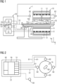
- Fig.1 shows a schematic representation of an embodiment of a magnetic resonance imaging device 1 for carrying out the method according to the invention.
- the magnet unit 10 has a field magnet 11 which generates a static magnetic field B0 for aligning nuclear spins of samples or of the patient 100 in a recording area.
- the recording area is characterized by an extremely homogeneous static magnetic field B0, the homogeneity relating in particular to the magnetic field strength or the amount.
- the recording area is almost spherical and arranged in a patient tunnel 16 which extends in a longitudinal direction 2 through the magnet unit 10.
- a patient bed 30 can be moved in the patient tunnel 16 by the movement unit 36.
- the field magnet 11 is usually a superconducting magnet which can provide magnetic fields with a magnetic flux density of up to 3T, and even more in the case of the latest devices. However, for lower magnetic field strengths, Permanent magnets or electromagnets with normally conducting coils are used.
- the magnet unit 10 has gradient coils 12, which are designed to superimpose temporally and spatially variable magnetic fields in three spatial directions on the magnetic field B0 for the spatial differentiation of the recorded imaging areas in the examination volume.
- the gradient coils 12 are usually coils made of normal conducting wires, which can generate mutually orthogonal fields in the examination volume.
- the magnet unit 10 also has a body coil 14 which is designed to emit a high-frequency signal supplied via a signal line into the examination volume and to receive resonance signals emitted by the patient 100 and to emit them via a signal line.
- a control unit 20 supplies the magnet unit 10 with the various signals for the gradient coils 12 and the body coil 14 and evaluates the received signals.
- control unit 20 has a gradient control 21 which is designed to supply the gradient coils 12 with variable currents via supply lines, which provide the desired gradient fields in the examination volume in a time-coordinated manner.
- control unit 20 has a high-frequency unit 22, which is designed to generate a high-frequency pulse with a predetermined time profile, amplitude and spectral power distribution for exciting a magnetic resonance of the nuclear spins in the patient 100. Pulse powers in the range of kilowatts can be achieved.
- the excitation signals can be emitted into the patient 100 via the body coil 14 or via a local transmitting antenna.
- a controller 23 communicates via a signal bus 25 with the gradient controller 21 and the high frequency unit 22.
- Sensors 60 are connected to an interference suppression device 70.
- the sensors 60 are preferably arranged in different spatial directions relative to the field of view of the magnetic resonance imaging device 1, so that the sensors 60 span a three-dimensional coordinate system. For example, as shown, three or more sensors 60 can be distributed along the circumference of the openings of the patient tunnel. Sensors 60 are preferably located at both opposite openings of the patient tunnel 16 in order to allow better location determination along the z-axis between the openings.
- the sensors 60 are, for example, induction loops that detect alternating magnetic fields and transmit them to the high-frequency unit 22 via signal connections 61.
- An interference suppression device 70 and locating device 80 are provided in the high-frequency unit 22, which receive and process the signals from the sensors 60.
- the interference suppression device 70 and the locating device 80 can be implemented on a common hardware, for example a signal processor as a software module or an FPGA. However, it is also conceivable that the interference suppression device 70 and the locating device 80 only have parts of the signal processing in common or are designed completely separately. Details of the interference suppression device 70 and the locating device 80 are given below. Fig. 2 explained in more detail.
- An instrument 90 according to the invention is located in the patient tunnel and transmits a location signal by means of the transponder 92, which is detected by the sensors 60.
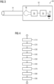
- Fig. 2 shows a schematic representation of a high frequency unit 22 of a magnetic resonance imaging device 1 according to the invention with a locating device 80 and an interference suppression device 70 as well as the sensors 60 and the instrument 90. Identical items are provided with the same reference symbols.
- the sensors 60 are arranged around the opening of the patient tunnel 16 and receive the locating signal from the instrument 90 or its transponder 92 there.
- the signals from the sensors 60 are forwarded to the high-frequency unit 22 via the signal connections 61.
- the signal is processed by receiver 51, for example amplified, filtered and, if not already done in the sensor 60, also digitized.
- the receivers 51 are preferably receivers that are also used to process the signals from the local coils 50 for image capture.
- the pre-processed signals from the sensors 60 are fed from the receivers 51 to the locating device 80 and/or the interference suppression device 70.
- the interference suppression device 70 is designed to detect electromagnetic interference using the sensors 60 and to reduce it by destructive interference in the magnetic resonance signals detected by the local coil 50.
- a source separation algorithm can be used, among other things, which can then also separate the signals from the sensors 60 according to the different sources, such as the locating signal and the sources of interference, which facilitates the subsequent evaluation of the locating signal.
- the locating signal from the transponder 92 may also represent an interference signal for the magnetic resonance signal, so that the interference suppression device 70 can advantageously use a locating signal detected by the locating device 80 to better suppress the locating signal in the magnetic resonance signals detected by the local coil 50 using the interference suppression device 70.
- the locating device 80 can evaluate the signals from the sensors 60 in different ways. For example, phase differences between the individual signals can be used as Differences in runtime and thus distances between the sensors 60 and the transponder 92 are evaluated. Depending on the frequency of the locating signal, it is also conceivable to use a phase shift of a modulated coding instead of the carrier wave itself in order to be able to detect runtimes greater than one period of the frequency of the locating signal.
- Pseudorandom sequences are suitable as coding, which can be evaluated by cross-correlation or autocorrelation using a correlator in the locating device.
- a pseudorandom sequence also advantageously makes it possible to detect and evaluate a signal below the noise limit with the correlator and thus minimize interference in the magnetic resonance signal.
- a different amplitude of the sensor signals can also be converted into a distance value as a distance-dependent attenuation of electrical and/or magnetic fields.
- the position of the transponder 92 can be determined based on the determined distances from the sensors 60. The error can be reduced in particular if the transponder 92 is arranged between the sensors 60, i.e. is enclosed by a polygon with sensors 60 at the corner points.
- the location can be determined using a location determination relation that receives the location signals received from the sensors 60 as input values and the coordinates of the relative position of the transponder 92 to the sensors 60 and thus to the magnetic resonance imaging device 1 as output values.
- An analytical solution is conceivable with 4 sensors.
- a larger number of sensors 60 provides an overdetermined system that represents, for example, an optimization problem that enables more precise and reliable position determination using an error minimization method such as least square root (LSR). Different results from amplitude and transit time can also be used in this overdetermined system to further improve position determination.
- LSR least square root
- the location determination relation is implemented by a neural network.
- the neural network can be trained with training data that is obtained by detecting the signals from the sensors 60 for predetermined training positions of the transponder 92. The relative positions determined by the neural network from these sensor signals are compared with the predetermined training positions and the deviations are reduced by means of back propagation.
- Fig.3 represents a possible embodiment of an instrument according to the invention.
- a transponder 92 is arranged on a surgical instrument such as a biopsy needle 91.
- the transponder 92 has an energy source 93, for example a battery or a rechargeable accumulator.
- a wireless energy supply via induction is also conceivable.
- the energy source 93 supplies the components of the transponder 92 with energy.
- An oscillator 94 generates a high-frequency alternating current, the frequency of which is preferably in a reception range of the receiver of the magnetic resonance tomograph 1 for the magnetic resonance signal.
- the high-frequency alternating current is modulated by a modulator 95 with a code that is designed to make the location signal distinguishable from magnetic resonance signals and/or interference signals. It is also conceivable that the code includes time information for time-of-flight detection.
- the location signal is then emitted by a transmitting antenna 96, for example an induction coil.
- the code is a modulation with a pseudorandom code.
- Pseudorandom code is understood to mean a signal or bit sequence that does not repeat within a predetermined period and is particularly suitable for the autocorrelation of a reference signal with a signal derived from it by transmission and allows a phase relationship or delay to be determined by this transmission.
- the transponder 92 does not generate the high-frequency signal independently, but is derived from a signal that the magnetic resonance tomograph 1 transmits to the transponder 92 via a wired or wireless connection.
- the locating signal can be generated from this, for example, by a frequency multiplier, frequency divider or PLL. In this way, a fixed frequency and phase relationship to the magnetic resonance signals can be advantageously ensured, which reduces any disruptive interaction with the magnetic resonance signals.
- the effect of the interference suppression device 70 is also better if the properties are precisely known, as is the case with a locating signal generated by the magnetic resonance tomograph 1.
- Fig.4 shows a schematic flow diagram of an embodiment of a method according to the invention.
- a coded locating signal is generated with the transponder 92, as already described Fig.3 was explained.
- the coded location signal is transmitted with the transponder 92, for example via its transmitting antenna 96.
- the location signal emitted by the transponder is detected or received in a step S40 by the plurality of sensors 60.
- the reception can also include preprocessing of the received signals by amplifiers, filters, frequency converters and/or A/D converters. Part of the preprocessing can also take place in the receivers 51 of the magnetic resonance imaging device 1.
- the locating signal is separated from other signals received by the sensors 60 by the locating device 80 and/or interference suppression device 70.
- a relative position of the transponder 92 relative to the sensors 60 is determined by the locating device 80 using the locating signal detected by the sensors 60 and a location determination relation applied thereto. It is conceivable, for example, to use an attenuation or runtime of the locating signal to determine the distance between the transponder 92 and the respective sensors 60. A processor of the locating device 60 can use this, for example, to determine a relative position of the sensor with the smallest possible error using an optimization problem. It is also conceivable to implement the location determination relation using a neural network.
- the locating device is calibrated or the neural network is trained by positioning the transponder 92 at a predetermined relative position to the sensors 60 in a step S10.
- steps S20 to S60 a relative position of the transponder 92 is determined using the locating device 80 and in a step S70 the location determination relation is calibrated or trained using the predetermined relative position and the determined relative position.
- a magnetic resonance image is calibrated using the locating device.
- a position of the instrument 90 with the transponder 92 is recorded in a magnetic resonance image.
- the instrument 90 has a marker that becomes visible in a magnetic resonance image, for example an active substance or an electrical resonator at the Larmor frequency. Imaging by means of artifacts that the instrument generates in an environment is also conceivable.
- the magnetic resonance image or the image reconstruction of the Magnetic resonance imaging devices calibrate or correct the magnetic resonance image by comparing the relative position detected by the locating device from steps S20 to S60 with the position in the magnetic resonance image.
Landscapes
- Health & Medical Sciences (AREA)
- Engineering & Computer Science (AREA)
- Surgery (AREA)
- Life Sciences & Earth Sciences (AREA)
- General Health & Medical Sciences (AREA)
- Physics & Mathematics (AREA)
- Medical Informatics (AREA)
- Heart & Thoracic Surgery (AREA)
- Biomedical Technology (AREA)
- Molecular Biology (AREA)
- Animal Behavior & Ethology (AREA)
- Robotics (AREA)
- Public Health (AREA)
- Veterinary Medicine (AREA)
- Nuclear Medicine, Radiotherapy & Molecular Imaging (AREA)
- Pathology (AREA)
- Condensed Matter Physics & Semiconductors (AREA)
- General Physics & Mathematics (AREA)
- Magnetic Resonance Imaging Apparatus (AREA)
Claims (9)
- Instrument d'examen ou d'intervention médical en utilisant un tomodensitomètre (1) à résonance magnétique, l'instrument (90) ayant au moins un transpondeur (92), qui est conçu pour émettre un signal de localisation dans un domaine de fréquence du tomodensitomètre (1) à résonance magnétique,
dans lequelle signal de localisation a un codage pour le distinguer d'un signal de résonance magnétique,dans lequel le transpondeur (92) a une source (93) d'énergie et un oscillateur (94), dans lequel l'oscillateur (94) est conçu pour produire le signal de localisation,caractérisé en ce quele transpondeur (92) a un modulateur (95), le codage est une modulation par un code pseudo-aléatoire et le modulateur (95) est conçu pour moduler le signal de localisation par le codage. - Instrument suivant la revendication 1, dans lequel le codage est un codage de fréquence dans un domaine de fréquence du tomodensitomètre (1) à résonance magnétique.
- Tomodensitomètre à résonance magnétique, dans lequel le tomodensitomètre (1) à résonance magnétique a une pluralité de capteurs (60) de détection d'un signal parasite et un dispositif (70) de déparasitage pour supprimer des signaux parasites de signaux de résonance magnétique reçus par des bobines locales,
caractérisé en ce quele tomodensitomètre à résonance magnétique a un dispositif (80) de localisation, qui est conçu pour enregistrer, par les capteurs (60), un signal de localisation d'un transpondeur (92) et pour déterminer ainsi une position relative du transpondeur, (92) par rapport aux capteurs (60),dans lequelle signal de localisation a un codage pour le distinguer d'un signal de résonance magnétique et le dispositif (80) de localisation du tomodensitomètre (1) à résonance magnétique est conçu pour, au moyen du codage, séparer des signaux parasites le signal de localisation du transpondeur (92) d'un instrument (90), au moyen. - Système composé d'un instrument d'examen médical ou d'intervention médicale, en utilisant un tomodensitomètre (1) à résonance magnétique, dans lequel l'instrument (90) a au moins un transpondeur (92), qui est conçu pour émettre un signal de localisation dans un domaine de fréquence du tomodensitomètre (1) à résonance magnétique,dans lequel le signal de localisation a un codage pour le distinguer d'un signal de résonance magnétique,et d'un tomodensitomètre (1) à résonance magnétique suivant la revendication 3,dans lequel le transpondeur (92) est conçu, pour produire un signal de localisation par un codage ou le tomodensitomètre (1) à résonance magnétique est conçu pour produire un signal de localisation par un codage et pour le transmettre par une ligne ou sans fil du tomodensitomètre à résonance magnétique au transpondeuret le dispositif (80) de localisation est conçu pour séparer, au moyen du codage, le signal de localisation du transpondeur (92) de signaux parasites, au moyen du codage.
- Procédé de détermination de la position relative d'un instrument (90) médical par un tomodensitomètre (1) à résonance magnétique, dans lequel l'instrument a un transpondeur (92) d'émission d'un signal de localisation, le tomodensitomètre (1) à résonance magnétique a une pluralité de capteurs (60) de détection du signal de localisation, dans lequel les capteurs (60) sont disposés en des positions différentes déterminées à l'avance autour du tunnel du patient et sous-tendent un espace à trois dimensions, dans lequel les capteurs (60) sont en liaison du signal avec un dispositif (80) de localisation,
dans lequel le procédé a les stades :(S20) production d'un signal codé de localisation par le transpondeur (92) ;(S30) émission du signal codé de localisation par le transpondeur (92) ;(S40) réception du signal de localisation par la pluralité des capteurs (60) ;(S50) séparation par le dispositif (80) de localisation du signal de localisation d'autres signaux reçus par les capteurs ;(S60) détermination par le dispositif (80) de localisation d'une position relative du transpondeur (92) par rapport aux capteurs, au moyen du signal de localisation détecté par les capteurs et d'une relation de détermination de localisation, qui y est appliquée. - Procédé suivant la revendication 5, dans lequel le procédé comporte en outre des stades :(S10) mise en position du transpondeur (92) en une position relative déterminée à l'avance par rapport aux capteurs (60) ;(S70) étalonnage de la relation de détermination de localisation à l'aide de la position relative déterminée à l'avance et de la position relative déterminée.
- Procédé suivant la revendication 5 ou 6, dans lequel le procédé comporte en outre les stades :(S80) détection d'une position d'instrument (90) par le transpondeur (92) dans un enregistrement de résonance magnétique ;(S90) étalonnage de l'enregistrement de résonance magnétique en fonction de la position détectée dans l'enregistrement de résonance magnétique du transpondeur (92) et de la position détectée dans le stade (S60) par le dispositif (80) de localisation.
- Produit de programme d'ordinateur, qui comprend un programme et qui peut être chargé directement dans la mémoire d'une commande (23) programmable d'un tomodensitomètre (1) à résonance magnétique suivant la revendication 3, comprenant des moyens de programme pour exécuter tous les stades du procédé suivant l'une des revendications 5 à 7, lorsque le programme est exécuté dans la commande (23) du tomodensitomètre (1) à résonance magnétique.
- Support de données déchiffrable électroniquement ayant des informations de commande déchiffrables électroniquement, qui sont mises en mémoire et qui sont conformées, de manière à ce qu'elles exécutent, lors de l'utilisation du support de données dans une commande (23) de tomodensitomètre (1) à résonance magnétique suivant la revendication 3, le procédé suivant l'une des revendications 5 à 7.
Priority Applications (2)
| Application Number | Priority Date | Filing Date | Title |
|---|---|---|---|
| EP21216119.4A EP4198544B1 (fr) | 2021-12-20 | 2021-12-20 | Instrument, tomographe à résonance magnétique et procédé de suivi de l'instrument |
| US18/080,912 US12369993B2 (en) | 2021-12-20 | 2022-12-14 | Instrument, magnetic resonance tomography system and method for tracking the instrument |
Applications Claiming Priority (1)
| Application Number | Priority Date | Filing Date | Title |
|---|---|---|---|
| EP21216119.4A EP4198544B1 (fr) | 2021-12-20 | 2021-12-20 | Instrument, tomographe à résonance magnétique et procédé de suivi de l'instrument |
Publications (2)
| Publication Number | Publication Date |
|---|---|
| EP4198544A1 EP4198544A1 (fr) | 2023-06-21 |
| EP4198544B1 true EP4198544B1 (fr) | 2024-09-18 |
Family
ID=78957542
Family Applications (1)
| Application Number | Title | Priority Date | Filing Date |
|---|---|---|---|
| EP21216119.4A Active EP4198544B1 (fr) | 2021-12-20 | 2021-12-20 | Instrument, tomographe à résonance magnétique et procédé de suivi de l'instrument |
Country Status (2)
| Country | Link |
|---|---|
| US (1) | US12369993B2 (fr) |
| EP (1) | EP4198544B1 (fr) |
Family Cites Families (8)
| Publication number | Priority date | Publication date | Assignee | Title |
|---|---|---|---|---|
| DE19755782A1 (de) * | 1997-12-16 | 1999-06-17 | Philips Patentverwaltung | MR-Anordnung mit einem medizinischen Instrument und Verfahren zur Positionsbestimmung des medizinischen Instruments |
| CN1849521B (zh) * | 2003-09-09 | 2010-06-16 | 皇家飞利浦电子股份有限公司 | 由磁共振成像监测的介入过程的导管尖端跟踪 |
| US7307420B2 (en) * | 2005-10-12 | 2007-12-11 | General Electric Company | MRI method for simultaneous phase contrast angiography and invasive device tracking |
| DE102006029122A1 (de) * | 2006-06-22 | 2007-12-27 | Amedo Gmbh | System zur Bestimmung der Position eines medizinischen Instrumentes |
| WO2009077934A1 (fr) * | 2007-12-18 | 2009-06-25 | Koninklijke Philips Electronics N.V. | Imagerie dynamique par résonance magnétique (irm) dotée d'une qualité d'image adaptative |
| WO2015150236A1 (fr) * | 2014-03-31 | 2015-10-08 | Koninklijke Philips N.V. | Imagerie par résonance magnétique au moyen de bobines de détection de bruit rf |
| DE102015208420A1 (de) * | 2015-05-06 | 2016-11-10 | Siemens Healthcare Gmbh | Temperaturermittlung mit Hilfe einer Interventionsvorrichtung |
| EP3467531A1 (fr) * | 2017-10-05 | 2019-04-10 | Siemens Healthcare GmbH | Appareil d'imagerie par résonance magnétique pourvu de dispositif d'antiparasitage actif et procédé d'antiparasitage dans un appareil d'imagerie par résonance magnétique |
-
2021
- 2021-12-20 EP EP21216119.4A patent/EP4198544B1/fr active Active
-
2022
- 2022-12-14 US US18/080,912 patent/US12369993B2/en active Active
Also Published As
| Publication number | Publication date |
|---|---|
| US20230190385A1 (en) | 2023-06-22 |
| EP4198544A1 (fr) | 2023-06-21 |
| US12369993B2 (en) | 2025-07-29 |
Similar Documents
| Publication | Publication Date | Title |
|---|---|---|
| EP4194875B1 (fr) | Tomographe à résonance magnétique à suppression active des parasites et procédé d'élimination des parasites dans un tomographe à résonance magnétique | |
| DE102015224158A1 (de) | Signalsender für Pilotton-Navigation | |
| EP3770624B1 (fr) | Procédés et dispositifs de prise en compte du signal de résonance magnétique lors d'un antiparasitage | |
| DE10254660B4 (de) | Verfahren zur Korrektur des B 1- Felds bei MR-Messungen und Magnetresonanz-Messeinrichtung | |
| DE102019208583B4 (de) | Pilottonvorrichtung, Magnetresonanztomograph mit Pilottonvorrichtung und Verfahren zum Betrieb | |
| DE102014222938B4 (de) | MR-Lokalspulensystem, MR-System und Verfahren zum Betreiben desselben | |
| DE112011104494T5 (de) | Verfahren zur Reduzierung der deponierten Leistung bei Magnetresonanz- Tomografie unter Verwendung von Vielband-Pulsen und Vielkanal-Übertragung | |
| EP3650878B1 (fr) | Bobine locale avec transmetteur de tonalité pilote | |
| DE102012207132B3 (de) | Ansteuerung eines Magnetresonanzsystems unter Ermittlung von Sendeskalierungsfaktoren für eine vorgegebene Zielmagnetisierung | |
| DE102017200446A1 (de) | Korrektur eines MR-Sendesignals | |
| EP3287805B1 (fr) | Dispositif et procédé de sécurité das par reconnaissance de non désaccordage de bobines d'antenne irm. | |
| DE102020208816A1 (de) | Vorrichtung und Verfahren zu aktiven lokalen Empfangsunterdrückung bei Magnetresonanzaufnahmen | |
| DE102020213938A1 (de) | Verfahren und Vorrichtung zur Störunterdrückung für MR-Ganzkörperantennen | |
| US20150377994A1 (en) | Method, apparatus, and article for frequency-overlapped 3-d multispectral magnetic resonance images | |
| DE102012210827B4 (de) | Bestimmung einer Kommunikationslatenz in einem Magnetresonanztomographen | |
| EP4198544B1 (fr) | Instrument, tomographe à résonance magnétique et procédé de suivi de l'instrument | |
| DE102013214307A1 (de) | Lokale Sendespulen / Sendespulenarray in der Wirbelsäulenbildgebung in einem MRI | |
| DE102015215476B4 (de) | Verfahren zur Verfolgung eines Markers in einem Untersuchungsobjekt mittels eines Magnetresonanztomographen sowie Magnetresonanztomograph | |
| DE102021210497A1 (de) | Entstörung von Magnetresonanztomographen | |
| EP4465068A1 (fr) | Tomographe à résonance magnétique pour localiser des objets métalliques et procédé de fonctionnement | |
| DE102020211606A1 (de) | Verfahren und Vorrichtung zur Unterdrückung von Störemissionen in Magnetresonanzsystemen | |
| EP3546974B1 (fr) | Procédé et dispositif de correction de l'inhomogénéité b0 au moyen d'un signal haute fréquence | |
| EP4063890B1 (fr) | Détection d'interférences rf dans un système de tomographie par résonance magnétique | |
| EP4253977A1 (fr) | Tomographe à résonance magnétique destiné à la localisation rapide, passive, tridimensionnelle des instruments et procédés de fonctionnement | |
| DE102020211439B4 (de) | Verfahren und Vorrichtung zur aktiven Unterdrückung von bei Magnetresonanzaufnahmen emittierten elektrischen und/oder magnetischen Feldern auf Grundlage eines angepassten Referenz- Feldprofils |
Legal Events
| Date | Code | Title | Description |
|---|---|---|---|
| PUAI | Public reference made under article 153(3) epc to a published international application that has entered the european phase |
Free format text: ORIGINAL CODE: 0009012 |
|
| STAA | Information on the status of an ep patent application or granted ep patent |
Free format text: STATUS: THE APPLICATION HAS BEEN PUBLISHED |
|
| AK | Designated contracting states |
Kind code of ref document: A1 Designated state(s): AL AT BE BG CH CY CZ DE DK EE ES FI FR GB GR HR HU IE IS IT LI LT LU LV MC MK MT NL NO PL PT RO RS SE SI SK SM TR |
|
| STAA | Information on the status of an ep patent application or granted ep patent |
Free format text: STATUS: REQUEST FOR EXAMINATION WAS MADE |
|
| 17P | Request for examination filed |
Effective date: 20231205 |
|
| RBV | Designated contracting states (corrected) |
Designated state(s): AL AT BE BG CH CY CZ DE DK EE ES FI FR GB GR HR HU IE IS IT LI LT LU LV MC MK MT NL NO PL PT RO RS SE SI SK SM TR |
|
| RAP1 | Party data changed (applicant data changed or rights of an application transferred) |
Owner name: SIEMENS HEALTHINEERS AG |
|
| GRAP | Despatch of communication of intention to grant a patent |
Free format text: ORIGINAL CODE: EPIDOSNIGR1 |
|
| STAA | Information on the status of an ep patent application or granted ep patent |
Free format text: STATUS: GRANT OF PATENT IS INTENDED |
|
| INTG | Intention to grant announced |
Effective date: 20240510 |
|
| GRAS | Grant fee paid |
Free format text: ORIGINAL CODE: EPIDOSNIGR3 |
|
| GRAA | (expected) grant |
Free format text: ORIGINAL CODE: 0009210 |
|
| STAA | Information on the status of an ep patent application or granted ep patent |
Free format text: STATUS: THE PATENT HAS BEEN GRANTED |
|
| AK | Designated contracting states |
Kind code of ref document: B1 Designated state(s): AL AT BE BG CH CY CZ DE DK EE ES FI FR GB GR HR HU IE IS IT LI LT LU LV MC MK MT NL NO PL PT RO RS SE SI SK SM TR |
|
| REG | Reference to a national code |
Ref country code: GB Ref legal event code: FG4D Free format text: NOT ENGLISH |
|
| REG | Reference to a national code |
Ref country code: CH Ref legal event code: EP |
|
| REG | Reference to a national code |
Ref country code: IE Ref legal event code: FG4D Free format text: LANGUAGE OF EP DOCUMENT: GERMAN |
|
| REG | Reference to a national code |
Ref country code: DE Ref legal event code: R096 Ref document number: 502021005175 Country of ref document: DE |
|
| REG | Reference to a national code |
Ref country code: LT Ref legal event code: MG9D |
|
| PG25 | Lapsed in a contracting state [announced via postgrant information from national office to epo] |
Ref country code: NO Free format text: LAPSE BECAUSE OF FAILURE TO SUBMIT A TRANSLATION OF THE DESCRIPTION OR TO PAY THE FEE WITHIN THE PRESCRIBED TIME-LIMIT Effective date: 20241218 |
|
| PG25 | Lapsed in a contracting state [announced via postgrant information from national office to epo] |
Ref country code: GR Free format text: LAPSE BECAUSE OF FAILURE TO SUBMIT A TRANSLATION OF THE DESCRIPTION OR TO PAY THE FEE WITHIN THE PRESCRIBED TIME-LIMIT Effective date: 20241219 Ref country code: FI Free format text: LAPSE BECAUSE OF FAILURE TO SUBMIT A TRANSLATION OF THE DESCRIPTION OR TO PAY THE FEE WITHIN THE PRESCRIBED TIME-LIMIT Effective date: 20240918 |
|
| PG25 | Lapsed in a contracting state [announced via postgrant information from national office to epo] |
Ref country code: BG Free format text: LAPSE BECAUSE OF FAILURE TO SUBMIT A TRANSLATION OF THE DESCRIPTION OR TO PAY THE FEE WITHIN THE PRESCRIBED TIME-LIMIT Effective date: 20240918 |
|
| PG25 | Lapsed in a contracting state [announced via postgrant information from national office to epo] |
Ref country code: LV Free format text: LAPSE BECAUSE OF FAILURE TO SUBMIT A TRANSLATION OF THE DESCRIPTION OR TO PAY THE FEE WITHIN THE PRESCRIBED TIME-LIMIT Effective date: 20240918 |
|
| PG25 | Lapsed in a contracting state [announced via postgrant information from national office to epo] |
Ref country code: HR Free format text: LAPSE BECAUSE OF FAILURE TO SUBMIT A TRANSLATION OF THE DESCRIPTION OR TO PAY THE FEE WITHIN THE PRESCRIBED TIME-LIMIT Effective date: 20240918 |
|
| REG | Reference to a national code |
Ref country code: NL Ref legal event code: MP Effective date: 20240918 |
|
| PG25 | Lapsed in a contracting state [announced via postgrant information from national office to epo] |
Ref country code: RS Free format text: LAPSE BECAUSE OF FAILURE TO SUBMIT A TRANSLATION OF THE DESCRIPTION OR TO PAY THE FEE WITHIN THE PRESCRIBED TIME-LIMIT Effective date: 20241218 |
|
| PG25 | Lapsed in a contracting state [announced via postgrant information from national office to epo] |
Ref country code: RS Free format text: LAPSE BECAUSE OF FAILURE TO SUBMIT A TRANSLATION OF THE DESCRIPTION OR TO PAY THE FEE WITHIN THE PRESCRIBED TIME-LIMIT Effective date: 20241218 Ref country code: NO Free format text: LAPSE BECAUSE OF FAILURE TO SUBMIT A TRANSLATION OF THE DESCRIPTION OR TO PAY THE FEE WITHIN THE PRESCRIBED TIME-LIMIT Effective date: 20241218 Ref country code: LV Free format text: LAPSE BECAUSE OF FAILURE TO SUBMIT A TRANSLATION OF THE DESCRIPTION OR TO PAY THE FEE WITHIN THE PRESCRIBED TIME-LIMIT Effective date: 20240918 Ref country code: HR Free format text: LAPSE BECAUSE OF FAILURE TO SUBMIT A TRANSLATION OF THE DESCRIPTION OR TO PAY THE FEE WITHIN THE PRESCRIBED TIME-LIMIT Effective date: 20240918 Ref country code: GR Free format text: LAPSE BECAUSE OF FAILURE TO SUBMIT A TRANSLATION OF THE DESCRIPTION OR TO PAY THE FEE WITHIN THE PRESCRIBED TIME-LIMIT Effective date: 20241219 Ref country code: FI Free format text: LAPSE BECAUSE OF FAILURE TO SUBMIT A TRANSLATION OF THE DESCRIPTION OR TO PAY THE FEE WITHIN THE PRESCRIBED TIME-LIMIT Effective date: 20240918 Ref country code: BG Free format text: LAPSE BECAUSE OF FAILURE TO SUBMIT A TRANSLATION OF THE DESCRIPTION OR TO PAY THE FEE WITHIN THE PRESCRIBED TIME-LIMIT Effective date: 20240918 |
|
| PG25 | Lapsed in a contracting state [announced via postgrant information from national office to epo] |
Ref country code: NL Free format text: LAPSE BECAUSE OF FAILURE TO SUBMIT A TRANSLATION OF THE DESCRIPTION OR TO PAY THE FEE WITHIN THE PRESCRIBED TIME-LIMIT Effective date: 20240918 |
|
| PG25 | Lapsed in a contracting state [announced via postgrant information from national office to epo] |
Ref country code: IS Free format text: LAPSE BECAUSE OF FAILURE TO SUBMIT A TRANSLATION OF THE DESCRIPTION OR TO PAY THE FEE WITHIN THE PRESCRIBED TIME-LIMIT Effective date: 20250118 Ref country code: PT Free format text: LAPSE BECAUSE OF FAILURE TO SUBMIT A TRANSLATION OF THE DESCRIPTION OR TO PAY THE FEE WITHIN THE PRESCRIBED TIME-LIMIT Effective date: 20250120 |
|
| PGFP | Annual fee paid to national office [announced via postgrant information from national office to epo] |
Ref country code: DE Payment date: 20250220 Year of fee payment: 4 |
|
| PG25 | Lapsed in a contracting state [announced via postgrant information from national office to epo] |
Ref country code: RO Free format text: LAPSE BECAUSE OF FAILURE TO SUBMIT A TRANSLATION OF THE DESCRIPTION OR TO PAY THE FEE WITHIN THE PRESCRIBED TIME-LIMIT Effective date: 20240918 Ref country code: SM Free format text: LAPSE BECAUSE OF FAILURE TO SUBMIT A TRANSLATION OF THE DESCRIPTION OR TO PAY THE FEE WITHIN THE PRESCRIBED TIME-LIMIT Effective date: 20240918 |
|
| PG25 | Lapsed in a contracting state [announced via postgrant information from national office to epo] |
Ref country code: ES Free format text: LAPSE BECAUSE OF FAILURE TO SUBMIT A TRANSLATION OF THE DESCRIPTION OR TO PAY THE FEE WITHIN THE PRESCRIBED TIME-LIMIT Effective date: 20240918 |
|
| PG25 | Lapsed in a contracting state [announced via postgrant information from national office to epo] |
Ref country code: EE Free format text: LAPSE BECAUSE OF FAILURE TO SUBMIT A TRANSLATION OF THE DESCRIPTION OR TO PAY THE FEE WITHIN THE PRESCRIBED TIME-LIMIT Effective date: 20240918 |
|
| PG25 | Lapsed in a contracting state [announced via postgrant information from national office to epo] |
Ref country code: CZ Free format text: LAPSE BECAUSE OF FAILURE TO SUBMIT A TRANSLATION OF THE DESCRIPTION OR TO PAY THE FEE WITHIN THE PRESCRIBED TIME-LIMIT Effective date: 20240918 Ref country code: PL Free format text: LAPSE BECAUSE OF FAILURE TO SUBMIT A TRANSLATION OF THE DESCRIPTION OR TO PAY THE FEE WITHIN THE PRESCRIBED TIME-LIMIT Effective date: 20240918 |
|
| PG25 | Lapsed in a contracting state [announced via postgrant information from national office to epo] |
Ref country code: SK Free format text: LAPSE BECAUSE OF FAILURE TO SUBMIT A TRANSLATION OF THE DESCRIPTION OR TO PAY THE FEE WITHIN THE PRESCRIBED TIME-LIMIT Effective date: 20240918 Ref country code: IT Free format text: LAPSE BECAUSE OF FAILURE TO SUBMIT A TRANSLATION OF THE DESCRIPTION OR TO PAY THE FEE WITHIN THE PRESCRIBED TIME-LIMIT Effective date: 20240918 |
|
| REG | Reference to a national code |
Ref country code: DE Ref legal event code: R097 Ref document number: 502021005175 Country of ref document: DE |
|
| PG25 | Lapsed in a contracting state [announced via postgrant information from national office to epo] |
Ref country code: MC Free format text: LAPSE BECAUSE OF FAILURE TO SUBMIT A TRANSLATION OF THE DESCRIPTION OR TO PAY THE FEE WITHIN THE PRESCRIBED TIME-LIMIT Effective date: 20240918 |
|
| PG25 | Lapsed in a contracting state [announced via postgrant information from national office to epo] |
Ref country code: DK Free format text: LAPSE BECAUSE OF FAILURE TO SUBMIT A TRANSLATION OF THE DESCRIPTION OR TO PAY THE FEE WITHIN THE PRESCRIBED TIME-LIMIT Effective date: 20240918 |
|
| PLBE | No opposition filed within time limit |
Free format text: ORIGINAL CODE: 0009261 |
|
| STAA | Information on the status of an ep patent application or granted ep patent |
Free format text: STATUS: NO OPPOSITION FILED WITHIN TIME LIMIT |
|
| REG | Reference to a national code |
Ref country code: CH Ref legal event code: PL |
|
| PG25 | Lapsed in a contracting state [announced via postgrant information from national office to epo] |
Ref country code: LU Free format text: LAPSE BECAUSE OF NON-PAYMENT OF DUE FEES Effective date: 20241220 |
|
| 26N | No opposition filed |
Effective date: 20250619 |
|
| PG25 | Lapsed in a contracting state [announced via postgrant information from national office to epo] |
Ref country code: SE Free format text: LAPSE BECAUSE OF FAILURE TO SUBMIT A TRANSLATION OF THE DESCRIPTION OR TO PAY THE FEE WITHIN THE PRESCRIBED TIME-LIMIT Effective date: 20240918 |
|
| REG | Reference to a national code |
Ref country code: BE Ref legal event code: MM Effective date: 20241231 |
|
| PG25 | Lapsed in a contracting state [announced via postgrant information from national office to epo] |
Ref country code: BE Free format text: LAPSE BECAUSE OF NON-PAYMENT OF DUE FEES Effective date: 20241231 |
|
| PG25 | Lapsed in a contracting state [announced via postgrant information from national office to epo] |
Ref country code: CH Free format text: LAPSE BECAUSE OF NON-PAYMENT OF DUE FEES Effective date: 20241231 |
|
| PG25 | Lapsed in a contracting state [announced via postgrant information from national office to epo] |
Ref country code: IE Free format text: LAPSE BECAUSE OF NON-PAYMENT OF DUE FEES Effective date: 20241220 |
|
| PGFP | Annual fee paid to national office [announced via postgrant information from national office to epo] |
Ref country code: AT Payment date: 20260113 Year of fee payment: 5 |
|
| PGFP | Annual fee paid to national office [announced via postgrant information from national office to epo] |
Ref country code: FR Payment date: 20251215 Year of fee payment: 5 |