EP4198347A1 - Chain guide assembly frame - Google Patents
Chain guide assembly frame Download PDFInfo
- Publication number
- EP4198347A1 EP4198347A1 EP22214584.9A EP22214584A EP4198347A1 EP 4198347 A1 EP4198347 A1 EP 4198347A1 EP 22214584 A EP22214584 A EP 22214584A EP 4198347 A1 EP4198347 A1 EP 4198347A1
- Authority
- EP
- European Patent Office
- Prior art keywords
- guide
- oil passage
- pivoting
- holding portion
- fixed
- Prior art date
- Legal status (The legal status is an assumption and is not a legal conclusion. Google has not performed a legal analysis and makes no representation as to the accuracy of the status listed.)
- Granted
Links
Images

Classifications
-
- F—MECHANICAL ENGINEERING; LIGHTING; HEATING; WEAPONS; BLASTING
- F01—MACHINES OR ENGINES IN GENERAL; ENGINE PLANTS IN GENERAL; STEAM ENGINES
- F01L—CYCLICALLY OPERATING VALVES FOR MACHINES OR ENGINES
- F01L1/00—Valve-gear or valve arrangements, e.g. lift-valve gear
- F01L1/02—Valve drive
- F01L1/022—Chain drive
-
- F—MECHANICAL ENGINEERING; LIGHTING; HEATING; WEAPONS; BLASTING
- F02—COMBUSTION ENGINES; HOT-GAS OR COMBUSTION-PRODUCT ENGINE PLANTS
- F02B—INTERNAL-COMBUSTION PISTON ENGINES; COMBUSTION ENGINES IN GENERAL
- F02B67/00—Engines characterised by the arrangement of auxiliary apparatus not being otherwise provided for, e.g. the apparatus having different functions; Driving auxiliary apparatus from engines, not otherwise provided for
- F02B67/04—Engines characterised by the arrangement of auxiliary apparatus not being otherwise provided for, e.g. the apparatus having different functions; Driving auxiliary apparatus from engines, not otherwise provided for of mechanically-driven auxiliary apparatus
- F02B67/06—Engines characterised by the arrangement of auxiliary apparatus not being otherwise provided for, e.g. the apparatus having different functions; Driving auxiliary apparatus from engines, not otherwise provided for of mechanically-driven auxiliary apparatus driven by means of chains, belts, or like endless members
-
- F—MECHANICAL ENGINEERING; LIGHTING; HEATING; WEAPONS; BLASTING
- F16—ENGINEERING ELEMENTS AND UNITS; GENERAL MEASURES FOR PRODUCING AND MAINTAINING EFFECTIVE FUNCTIONING OF MACHINES OR INSTALLATIONS; THERMAL INSULATION IN GENERAL
- F16H—GEARING
- F16H57/00—General details of gearing
- F16H57/04—Features relating to lubrication or cooling or heating
- F16H57/042—Guidance of lubricant
-
- F—MECHANICAL ENGINEERING; LIGHTING; HEATING; WEAPONS; BLASTING
- F16—ENGINEERING ELEMENTS AND UNITS; GENERAL MEASURES FOR PRODUCING AND MAINTAINING EFFECTIVE FUNCTIONING OF MACHINES OR INSTALLATIONS; THERMAL INSULATION IN GENERAL
- F16H—GEARING
- F16H57/00—General details of gearing
- F16H57/04—Features relating to lubrication or cooling or heating
- F16H57/042—Guidance of lubricant
- F16H57/0421—Guidance of lubricant on or within the casing, e.g. shields or baffles for collecting lubricant, tubes, pipes, grooves, channels or the like
- F16H57/0424—Lubricant guiding means in the wall of or integrated with the casing, e.g. grooves, channels, holes
-
- F—MECHANICAL ENGINEERING; LIGHTING; HEATING; WEAPONS; BLASTING
- F16—ENGINEERING ELEMENTS AND UNITS; GENERAL MEASURES FOR PRODUCING AND MAINTAINING EFFECTIVE FUNCTIONING OF MACHINES OR INSTALLATIONS; THERMAL INSULATION IN GENERAL
- F16H—GEARING
- F16H57/00—General details of gearing
- F16H57/04—Features relating to lubrication or cooling or heating
- F16H57/048—Type of gearings to be lubricated, cooled or heated
- F16H57/0487—Friction gearings
- F16H57/0489—Friction gearings with endless flexible members, e.g. belt CVTs
-
- F—MECHANICAL ENGINEERING; LIGHTING; HEATING; WEAPONS; BLASTING
- F16—ENGINEERING ELEMENTS AND UNITS; GENERAL MEASURES FOR PRODUCING AND MAINTAINING EFFECTIVE FUNCTIONING OF MACHINES OR INSTALLATIONS; THERMAL INSULATION IN GENERAL
- F16H—GEARING
- F16H57/00—General details of gearing
- F16H57/04—Features relating to lubrication or cooling or heating
- F16H57/05—Features relating to lubrication or cooling or heating of chains
-
- F—MECHANICAL ENGINEERING; LIGHTING; HEATING; WEAPONS; BLASTING
- F16—ENGINEERING ELEMENTS AND UNITS; GENERAL MEASURES FOR PRODUCING AND MAINTAINING EFFECTIVE FUNCTIONING OF MACHINES OR INSTALLATIONS; THERMAL INSULATION IN GENERAL
- F16H—GEARING
- F16H7/00—Gearings for conveying rotary motion by endless flexible members
- F16H7/08—Means for varying tension of belts, ropes or chains
-
- F—MECHANICAL ENGINEERING; LIGHTING; HEATING; WEAPONS; BLASTING
- F16—ENGINEERING ELEMENTS AND UNITS; GENERAL MEASURES FOR PRODUCING AND MAINTAINING EFFECTIVE FUNCTIONING OF MACHINES OR INSTALLATIONS; THERMAL INSULATION IN GENERAL
- F16H—GEARING
- F16H7/00—Gearings for conveying rotary motion by endless flexible members
- F16H7/18—Means for guiding or supporting belts, ropes, or chains
-
- F—MECHANICAL ENGINEERING; LIGHTING; HEATING; WEAPONS; BLASTING
- F02—COMBUSTION ENGINES; HOT-GAS OR COMBUSTION-PRODUCT ENGINE PLANTS
- F02F—CYLINDERS, PISTONS OR CASINGS, FOR COMBUSTION ENGINES; ARRANGEMENTS OF SEALINGS IN COMBUSTION ENGINES
- F02F7/00—Casings, e.g. crankcases
- F02F7/0065—Shape of casings for other machine parts and purposes, e.g. utilisation purposes, safety
- F02F7/0073—Adaptations for fitting the engine, e.g. front-plates or bell-housings
- F02F2007/0075—Front covers
-
- F—MECHANICAL ENGINEERING; LIGHTING; HEATING; WEAPONS; BLASTING
- F16—ENGINEERING ELEMENTS AND UNITS; GENERAL MEASURES FOR PRODUCING AND MAINTAINING EFFECTIVE FUNCTIONING OF MACHINES OR INSTALLATIONS; THERMAL INSULATION IN GENERAL
- F16H—GEARING
- F16H7/00—Gearings for conveying rotary motion by endless flexible members
- F16H7/08—Means for varying tension of belts, ropes or chains
- F16H2007/0842—Mounting or support of tensioner
-
- F—MECHANICAL ENGINEERING; LIGHTING; HEATING; WEAPONS; BLASTING
- F16—ENGINEERING ELEMENTS AND UNITS; GENERAL MEASURES FOR PRODUCING AND MAINTAINING EFFECTIVE FUNCTIONING OF MACHINES OR INSTALLATIONS; THERMAL INSULATION IN GENERAL
- F16H—GEARING
- F16H7/00—Gearings for conveying rotary motion by endless flexible members
- F16H7/08—Means for varying tension of belts, ropes or chains
- F16H2007/0863—Finally actuated members, e.g. constructional details thereof
- F16H2007/0872—Sliding members
-
- F—MECHANICAL ENGINEERING; LIGHTING; HEATING; WEAPONS; BLASTING
- F16—ENGINEERING ELEMENTS AND UNITS; GENERAL MEASURES FOR PRODUCING AND MAINTAINING EFFECTIVE FUNCTIONING OF MACHINES OR INSTALLATIONS; THERMAL INSULATION IN GENERAL
- F16H—GEARING
- F16H7/00—Gearings for conveying rotary motion by endless flexible members
- F16H7/08—Means for varying tension of belts, ropes or chains
- F16H2007/0889—Path of movement of the finally actuated member
- F16H2007/0893—Circular path
-
- F—MECHANICAL ENGINEERING; LIGHTING; HEATING; WEAPONS; BLASTING
- F16—ENGINEERING ELEMENTS AND UNITS; GENERAL MEASURES FOR PRODUCING AND MAINTAINING EFFECTIVE FUNCTIONING OF MACHINES OR INSTALLATIONS; THERMAL INSULATION IN GENERAL
- F16H—GEARING
- F16H7/00—Gearings for conveying rotary motion by endless flexible members
- F16H7/08—Means for varying tension of belts, ropes or chains
- F16H2007/0889—Path of movement of the finally actuated member
- F16H2007/0897—External to internal direction
-
- F—MECHANICAL ENGINEERING; LIGHTING; HEATING; WEAPONS; BLASTING
- F16—ENGINEERING ELEMENTS AND UNITS; GENERAL MEASURES FOR PRODUCING AND MAINTAINING EFFECTIVE FUNCTIONING OF MACHINES OR INSTALLATIONS; THERMAL INSULATION IN GENERAL
- F16H—GEARING
- F16H7/00—Gearings for conveying rotary motion by endless flexible members
- F16H7/18—Means for guiding or supporting belts, ropes, or chains
- F16H2007/185—Means for guiding or supporting belts, ropes, or chains the guiding surface in contact with the belt, rope or chain having particular shapes, structures or materials
-
- F—MECHANICAL ENGINEERING; LIGHTING; HEATING; WEAPONS; BLASTING
- F16—ENGINEERING ELEMENTS AND UNITS; GENERAL MEASURES FOR PRODUCING AND MAINTAINING EFFECTIVE FUNCTIONING OF MACHINES OR INSTALLATIONS; THERMAL INSULATION IN GENERAL
- F16H—GEARING
- F16H7/00—Gearings for conveying rotary motion by endless flexible members
- F16H7/06—Gearings for conveying rotary motion by endless flexible members with chains
Definitions
- the present invention relates to a chain guide assembly frame used, for instance, in a timing system of an engine.
- the tensioner lever described in Japanese Patent Application Publication No. 2009-036273 has a conventionally known configuration for efficient use of lubricating oil in a chain guide assembly used, for instance, in a timing system of an engine.
- the pivoting chain guide (tensioner lever 100) described in Japanese Patent Application Publication No. 2009-036273 is attached to an inner wall E of an engine via a pivot shaft (shoulder bolt SB) passed through an axial support boss 130.
- An oil guide groove 131 is formed by cutting off an outer peripheral portion of the axial support boss 130 radially inward to guide oil (engine oil O) that gathered and adhered on the lever body 120 toward a bolt passage area 132 of the axial support boss 130.
- the oil (engine oil O) on the inner wall E of the engine can be maximally utilized as lubricating oil in an efficient manner to suppress galling, seizure, uneven wear, and friction loss that the pivot shaft (shoulder bolt SB) tends to suffer and favorable durability can be ensured.
- Smooth pivoting motion of the chain guide to follow the movement of the drive chain C can be also ensured, giving a correct tension to the chain in concert with a tensioner T.
- An oil communication passage 123 integrally formed to the lever body 120 at the foot of inclined reinforcing ribs 122 also ensures smooth continuous flow of the oil (engine oil O) that gathered and adhered on the entire lever body 120 from the distal end to the base end without being stopped by the reinforcing ribs 122. This way, the excess oil (engine oil O) gathering and adhering on the entire lever body 120 can be supplied into the oil guide groove 131 at the base end efficiently.
- the pivoting chain guide described in Japanese Patent Application Publication No. 2009-036273 is designed to suppress galling, seizure, uneven wear, and friction loss of the pivot shaft by collecting and guiding the oil that adhered to the lever body toward the pivot shaft.
- oil that adhered to other parts of the chain guide assembly than the pivoting chain guide is not collected or guided.
- Efficient use of the oil for other parts than the pivoting chain guide is not possible when, for example, the chain, or a fixed chain guide that slidably guides the chain, or a drive sprocket the chain is passed around, are not supplied with sufficient oil. As a result, the overall amount of use of the oil has to be increased.
- the present invention solves these problems, and aims at providing a chain guide assembly frame capable of efficiently collecting the oil that adhered to various parts of the chain guide assembly, and guiding the collected oil to predetermined locations, to allow efficient use of oil, with a simple structure.
- the present invention solves the above problems by providing a chain guide assembly frame including a main body and a driven sprocket holding portion that clamps a driven sprocket in an upper part of the main body, the main body including a fixed chain guide, and a pivoting chain guide holding portion to which a pivoting chain guide is mountable.
- the driven sprocket holding portion includes a fixed-guide-side sprocket holding portion provided on a fixed chain guide side, and a pivoting-guide-side sprocket holding portion provided on a pivoting chain guide holding portion side.
- the main body includes a drive sprocket holding portion holding a drive sprocket and located lower than the driven sprocket holding portion.
- the main body includes a concave and/or convex oil passage extending from an upper part toward a lower part to guide oil toward above the drive sprocket holding portion.
- the chain guide assembly frame according to claim 1 includes a concave and/or convex oil passage in the main body, extending from an upper part downward to guide oil toward an area above the drive sprocket holding portion.
- the oil that adhered in the upper part of the main body is thus collected into the oil passage, and reliably guided toward the drive sprocket holding portion in the lower part of the main body. Therefore, the drive sprocket can be lubricated sufficiently with a reduced amount of oil compared to the case where no oil passage is provided.
- the oil passage at a lower end thereof on a drive sprocket holding portion side, diverges into a fixed-guide-side oil passage formed extending toward the fixed chain guide and a pivoting-guide-side oil passage formed extending toward the pivoting chain guide holding portion.
- the oil that adhered in the upper part of the main body can be guided not only to the drive sprocket but also to the fixed chain guide that makes sliding contact with the chain, and the pivoting chain guide holding portion.
- Various parts can be supplied with oil in a more efficient manner in this way and sufficiently lubricated with a reduced amount of oil compared to the case where no oil passage is provided.
- the main body includes a top guide.
- the oil passage includes an upper oil passage formed extending from the top guide through between the fixed-guide-side sprocket holding portion and the pivoting-guide-side sprocket holding portion, and a lower oil passage formed at a position lower than the upper oil passage.
- the oil that adhered around the top guide can be reliably collected into the upper oil passage, and guided to between the fixed-guide-side sprocket holding portion and the pivoting-guide-side sprocket holding portion.
- the oil guided from the upper oil passage is then guided to various parts from the lower oil passage. Various parts can thus be supplied with oil in a more efficient manner.
- the upper oil passage has a lower end formed to be positioned directly above a topmost part of the lower oil passage.
- the lower oil passage may diverge midway, but the oil is guided directly from the upper oil passage to the lower oil passage before the diverging point, so that a sufficient amount of oil can be reliably guided from the upper oil passage to both destinations of the diverged lower oil passage.
- the upper oil passage diverges to have a lower end formed to be positioned directly above the fixed-guide-side lower oil passage and a lower end formed to be positioned directly above the pivoting-guide-side lower oil passage. Therefore, the oil can be guided reliably and sufficiently from the upper oil passage to both of the fixed-guide-side lower oil passage and pivoting-guide-side lower oil passage.
- the upper oil passage includes a fixed-guide-side upper oil passage formed on a fixed-guide-side sprocket holding portion side, and a pivoting-guide-side upper oil passage formed on a pivoting-guide-side sprocket holding portion side.
- a substantial amount of oil that adhered to a wide area of the top guide can be collected, so that more oil can be guided to various parts through the oil passage.
- the fixed-guide-side upper oil passage has a lower end formed to be positioned directly above the fixed-guide-side lower oil passage
- the pivoting-guide-side upper oil passage has a lower end formed to be positioned directly above the pivoting-guide-side lower oil passage.
- the pivoting-guide-side oil passage has a lower end formed to be positioned directly above the drive sprocket holding portion. Therefore, oil can be guided reliably from the upper part of the main body to the drive sprocket holding portion.
- the oil passage is formed in a weld bead shape. Therefore, the oil passage, which may be either concave or convex, can be formed on both front and back sides of the main body by a single machining process.
- the oil passage formed as a weld bead on the surface of the main body can increase the strength of the main body itself.
- a chain guide assembly frame 100 according to one embodiment of the present invention will be hereinafter described with reference to the drawings.
- FIG. 2 does not illustrate the engine, or connection members that connect the engine and the frame 100.
- the chain guide assembly frame 100 includes a main body 110, a top guide 115 provided on the upper surface of the main body 110, a fixed chain guide 111 provided on one side face of the main body 110, and a pivoting chain guide holding portion 114 to which a pivoting chain guide 112 can be attached on a side face of the main body 110 opposite from the fixed chain guide 111.
- a fixed-guide-side sprocket holding portion 120 is provided in an upper part of the main body 110 on the same side as the fixed chain guide 111
- a pivoting-guide-side sprocket holding portion 121 is provided in an upper part of the main body 110 on the same side as the pivoting chain guide holding portion 114.
- a drive sprocket holding portion 122 that can hold a drive sprocket DS is provided in a lower part of the main body 110.
- Mounting holes H1, H2, H3 used when fixing the frame to an engine (not shown) are provided in various parts of the main body 110.
- An oil passage including a fixed-guide-side upper oil passage 130 and a pivoting-guide-side upper oil passage 131 is formed in a vertically extending weld bead shape, i.e., convex on one side of the main body 110 and concave on the other side, each extending from near the top guide 115 between the fixed-guide-side sprocket holding portion 120 and the pivoting-guide-side sprocket holding portion 121 as far as to near the mounting hole H2.
- a fixed-guide-side lower oil passage 132 that is an oil passage extending from near the mounting hole H2 gradually downward and toward the fixed chain guide 111
- a pivoting-guide-side lower oil passage 133 that is an oil passage extending from near the mounting hole H2 gradually downward as far as to near the drive sprocket holding portion 122, passing on the side of the pivoting chain guide holding portion 114 of the main body 110.
- the fixed-guide-side lower oil passage 132 and pivoting-guide-side lower oil passage 133 are connected at their tops near the mounting hole H2.
- An auxiliary oil passage 134 that is an oil passage running parallel to a lower part of the pivoting-guide-side lower oil passage 133 is formed below the mounting hole H3.
- the fixed-guide-side lower oil passage 132, pivoting-guide-side lower oil passage 133, and auxiliary oil passage 134 are formed as weld beads similarly to the fixed-guide-side upper oil passage 130 and pivoting-guide-side upper oil passage 131.
- fixed-guide-side upper oil passage 130, pivoting-guide-side upper oil passage 131, fixed-guide-side lower oil passage 132, pivoting-guide-side lower oil passage 133 and auxiliary oil passage 134 are formed as weld beads as described above, they can help minimize deflection of the main body 110 and increase the strength.
- the chain guide assembly frame 100 holds a driven sprocket S1 in the fixed-guide-side sprocket holding portion 120, holds a driven sprocket S2 in the pivoting-guide-side sprocket holding portion 121, and holds a drive sprocket DS in the drive sprocket holding portion 122.
- a chain CH is passed around the driven sprockets S1 and S2, and drive sprocket DS.
- the pivoting chain guide 112 is pivotably connected to the pivoting chain guide holding portion 114 via a pivot shaft 113, to press the chain CH and create a predetermined tension in the chain CH.
- the chain CH is passed around such as to make sliding contact with the fixed chain guide 111, pivoting chain guide 112, and top guide 115.
- the chain guide assembly frame 100 is attached to the engine (not shown) via the mounting holes H1, H2, and H3 in this state.
- Oil EL is supplied to the chain guide assembly attached to the engine (not shown) for lubricating the chain CH and various parts of the chain guide assembly.
- Some of the oil EL in mist form floating around the frame 100 of the chain guide assembly also adheres to the main body 110.
- the oil EL While it depends on from where the oil EL is supplied, the oil EL generally adheres more in upper parts of the main body 110 and flows down slowly along the main body 110.
- the oil EL 1 that adhered around the fixed-guide-side sprocket holding portion 120 near the top guide 115 is collected in the fixed-guide-side upper oil passage 130.
- the oil EL 2 that adhered around the pivoting-guide-side sprocket holding portion 121 near the top guide 115 is collected in the pivoting-guide-side upper oil passage 131.
- the oil EL 1 and EL 2 after traveling along the respective weld bead shapes of the fixed-guide-side upper oil passage 130 and pivoting-guide-side upper oil passage 131 and reaching the lower ends, flows down from the respective oil passages.
- the fixed-guide-side upper oil passage 130 and pivoting-guide-side upper oil passage 131 have their respective upper ends positioned closer to the fixed-guide-side sprocket holding portion 120 and pivoting-guide-side sprocket holding portion 121, and lower ends positioned closer to the center of the main body 110. Therefore, oil EL 1 and EL 2 that adhered to the main body 110 above the fixed-guide-side upper oil passage 130 and pivoting-guide-side upper oil passage 131 can be efficiently collected from a wide area.
- the oil EL 1 and EL 2 that flowed down from the respective lower ends of the fixed-guide-side upper oil passage 130 and pivoting-guide-side upper oil passage 131 is collected respectively in the fixed-guide-side lower oil passage 132 and pivoting-guide-side lower oil passage 133, and flows down from the lower ends along the weld bead shapes of the fixed-guide-side lower oil passage 132 and pivoting-guide-side lower oil passage 133.
- the oil EL 1 collected from around the top guide 115 is supplied to the fixed chain guide 111, whereby the slidability of the chain CH on the fixed chain guide 111 can be more improved.
- the oil EL 2 collected from around the top guide 115 is supplied to the drive sprocket DS.
- the drive sprocket DS can thus be lubricated in an efficient manner, and the oil EL 2 can be further supplied to the chain CH via the drive sprocket DS.
- the pivoting-guide-side lower oil passage 133 extends along the main body 110 on the side of the pivoting chain guide holding portion 114 down to directly above the drive sprocket holding portion 122 and is not configured to collect oil EL 3 that adhered above the mounting hole H3 of the main body 110.
- the auxiliary oil passage 134 is formed below the mounting hole H3 so that the oil EL 3 is collected in the auxiliary oil passage 134.
- the oil EL 3 is also supplied to the drive sprocket DS.
- the drive sprocket DS can thus be lubricated more efficiently.
- the oil EL that adhered to the main body 110 is collected in this way by the fixed-guide-side upper oil passage 130, pivoting-guide-side upper oil passage 131, fixed-guide-side lower oil passage 132, pivoting-guide-side lower oil passage 133, and auxiliary oil passage 134, and guided to predetermined locations. Therefore, various parts such as the chain CH and drive sprocket DS can be efficiently lubricated using a reduced amount of oil EL as compared to the case in which no oil passages are provided.
- a fixed-guide-side upper oil passage and a pivoting-guide-side upper oil passage are formed in an upper part of the main body.
- the configuration of the oil passages to be provided in an upper part of the main body is not limited to this example.
- a fixed-guide-side upper oil passage and a pivoting-guide-side upper oil passage may be formed such as to merge on their way down, for example.
- One oil passage extending from an upper part of the main body may split into a fixed-guide-side upper oil passage and a pivoting-guide-side upper oil passage somewhere along the way down.
- the main body may be formed with only one oil passage.
- a fixed-guide-side lower oil passage and a pivoting-guide-side lower oil passage are formed below the fixed-guide-side upper oil passage and pivoting-guide-side upper oil passage, and the upper ends of the fixed-guide-side lower oil passage and pivoting-guide-side lower oil passage are joined together.
- the configurations of the fixed-guide-side lower oil passage and pivoting-guide-side lower oil passage are not limited to this example.
- the fixed-guide-side lower oil passage and pivoting-guide-side lower oil passage may not be joined together, for example. There may be no fixed-guide-side lower oil passage or pivoting-guide-side lower oil passage.
- the lower end of the fixed-guide-side upper oil passage may be connected to the upper end of the fixed-guide-side lower oil passage.
- the lower end of the fixed-guide-side lower oil passage is positioned above the fixed chain guide.
- the fixed-guide-side lower oil passage may have its lower end positioned anywhere, below the fixed chain guide for example, or directly above the mounting hole H3.
- the lower end of the pivoting-guide-side lower oil passage is positioned directly above the drive sprocket holding portion.
- the pivoting-guide-side lower oil passage may have its lower end positioned anywhere, directly above the pivoting chain guide holding portion for example, or, the pivoting-guide-side lower oil passage may diverge somewhere to have lower ends, one directly above the pivoting chain guide holding portion and the other directly above the drive sprocket holding portion.
- auxiliary oil passage is formed below the mounting hole H3 in the above-described embodiment, the configuration of the auxiliary oil passage is not limited to this example. There may be no auxiliary oil passage for example, or an auxiliary oil passage may be formed above the mounting hole H3 such that its lower end merges with the pivoting-guide-side lower oil passage.
- top guide is provided at the top of the main body in the above-described embodiment, the frame configuration of the chain guide assembly is not limited to this example.
- the top guide may be omitted, for example.
- oil passages described in the embodiment above are formed in a weld bead shape, the configuration of the oil passages is not limited to this example.
- the oil passages may be formed as grooves that are concave on both sides of the main body, for example, or as ridges protruding from both sides of the main body. Alternatively, the oil passages may be formed only on one side of the main body.
Landscapes
- Engineering & Computer Science (AREA)
- General Engineering & Computer Science (AREA)
- Mechanical Engineering (AREA)
- Chemical & Material Sciences (AREA)
- Combustion & Propulsion (AREA)
- Devices For Conveying Motion By Means Of Endless Flexible Members (AREA)
- General Details Of Gearings (AREA)
- Cylinder Crankcases Of Internal Combustion Engines (AREA)
- Lubrication Of Internal Combustion Engines (AREA)
Abstract
Description
- The present invention relates to a chain guide assembly frame used, for instance, in a timing system of an engine.
- The tensioner lever described in
Japanese Patent Application Publication No. 2009-036273 - The pivoting chain guide (tensioner lever 100) described in
Japanese Patent Application Publication No. 2009-036273 axial support boss 130. Anoil guide groove 131 is formed by cutting off an outer peripheral portion of theaxial support boss 130 radially inward to guide oil (engine oil O) that gathered and adhered on thelever body 120 toward abolt passage area 132 of theaxial support boss 130. - Thus, when the lever is attached to the inner wall E of the engine, with the lengthwise distal end of the lever being oriented upward and the
axial support boss 130 at the lengthwise base end of the lever being oriented downward, the oil (engine oil O) that gathered and adhered on the inner wall E of the engine flows down along both front and back sides of thelever body 120 and infiltrates the entirebolt passage area 132 of theaxial support boss 130, regardless of whether theaxial support boss 130 is making tight contact with the inner wall E of the engine or with a flange Sf of the pivot shaft (shoulder bolt SB). This way, the oil (engine oil O) on the inner wall E of the engine can be maximally utilized as lubricating oil in an efficient manner to suppress galling, seizure, uneven wear, and friction loss that the pivot shaft (shoulder bolt SB) tends to suffer and favorable durability can be ensured. Smooth pivoting motion of the chain guide to follow the movement of the drive chain C can be also ensured, giving a correct tension to the chain in concert with a tensioner T. - An oil communication passage 123 integrally formed to the
lever body 120 at the foot of inclined reinforcingribs 122 also ensures smooth continuous flow of the oil (engine oil O) that gathered and adhered on theentire lever body 120 from the distal end to the base end without being stopped by the reinforcingribs 122. This way, the excess oil (engine oil O) gathering and adhering on theentire lever body 120 can be supplied into theoil guide groove 131 at the base end efficiently. - The configuration for efficient use of lubricating oil in the pivoting chain guide described in
Japanese Patent Application Publication No. 2009-036273 - Namely, the pivoting chain guide described in
Japanese Patent Application Publication No. 2009-036273 - The present invention solves these problems, and aims at providing a chain guide assembly frame capable of efficiently collecting the oil that adhered to various parts of the chain guide assembly, and guiding the collected oil to predetermined locations, to allow efficient use of oil, with a simple structure.
- The present invention solves the above problems by providing a chain guide assembly frame including a main body and a driven sprocket holding portion that clamps a driven sprocket in an upper part of the main body, the main body including a fixed chain guide, and a pivoting chain guide holding portion to which a pivoting chain guide is mountable. The driven sprocket holding portion includes a fixed-guide-side sprocket holding portion provided on a fixed chain guide side, and a pivoting-guide-side sprocket holding portion provided on a pivoting chain guide holding portion side. The main body includes a drive sprocket holding portion holding a drive sprocket and located lower than the driven sprocket holding portion. The main body includes a concave and/or convex oil passage extending from an upper part toward a lower part to guide oil toward above the drive sprocket holding portion.
- The chain guide assembly frame according to
claim 1 includes a concave and/or convex oil passage in the main body, extending from an upper part downward to guide oil toward an area above the drive sprocket holding portion. The oil that adhered in the upper part of the main body is thus collected into the oil passage, and reliably guided toward the drive sprocket holding portion in the lower part of the main body. Therefore, the drive sprocket can be lubricated sufficiently with a reduced amount of oil compared to the case where no oil passage is provided. - According to the configuration set forth in
claim 2, the oil passage, at a lower end thereof on a drive sprocket holding portion side, diverges into a fixed-guide-side oil passage formed extending toward the fixed chain guide and a pivoting-guide-side oil passage formed extending toward the pivoting chain guide holding portion. The oil that adhered in the upper part of the main body can be guided not only to the drive sprocket but also to the fixed chain guide that makes sliding contact with the chain, and the pivoting chain guide holding portion. Various parts can be supplied with oil in a more efficient manner in this way and sufficiently lubricated with a reduced amount of oil compared to the case where no oil passage is provided. - According to the configuration set forth in claim 3, the main body includes a top guide. The oil passage includes an upper oil passage formed extending from the top guide through between the fixed-guide-side sprocket holding portion and the pivoting-guide-side sprocket holding portion, and a lower oil passage formed at a position lower than the upper oil passage. The oil that adhered around the top guide can be reliably collected into the upper oil passage, and guided to between the fixed-guide-side sprocket holding portion and the pivoting-guide-side sprocket holding portion. The oil guided from the upper oil passage is then guided to various parts from the lower oil passage. Various parts can thus be supplied with oil in a more efficient manner.
- According to the configuration set forth in claim 4, the upper oil passage has a lower end formed to be positioned directly above a topmost part of the lower oil passage. The lower oil passage may diverge midway, but the oil is guided directly from the upper oil passage to the lower oil passage before the diverging point, so that a sufficient amount of oil can be reliably guided from the upper oil passage to both destinations of the diverged lower oil passage.
- According to the configuration set forth in claim 5, the upper oil passage diverges to have a lower end formed to be positioned directly above the fixed-guide-side lower oil passage and a lower end formed to be positioned directly above the pivoting-guide-side lower oil passage. Therefore, the oil can be guided reliably and sufficiently from the upper oil passage to both of the fixed-guide-side lower oil passage and pivoting-guide-side lower oil passage.
- According to the configuration set forth in claim 6, the upper oil passage includes a fixed-guide-side upper oil passage formed on a fixed-guide-side sprocket holding portion side, and a pivoting-guide-side upper oil passage formed on a pivoting-guide-side sprocket holding portion side. In the case where the top guide stretches over a wide area as far as above the fixed-guide-side sprocket holding portion and pivoting-guide-side sprocket holding portion, a substantial amount of oil that adhered to a wide area of the top guide can be collected, so that more oil can be guided to various parts through the oil passage.
- According to the configuration set forth in claim 7, the fixed-guide-side upper oil passage has a lower end formed to be positioned directly above the fixed-guide-side lower oil passage, and the pivoting-guide-side upper oil passage has a lower end formed to be positioned directly above the pivoting-guide-side lower oil passage. The amount of oil collected from near the top guide by each of the fixed-guide-side upper oil passage and pivoting-guide-side upper oil passage can be adjusted by varying the positions or shapes of their upper ends. The ratio of oil to be supplied to the fixed-guide-side lower oil passage and pivoting-guide-side lower oil passage can thus be adjusted to guide an adequate amount of oil to various parts for even more suitable lubrication.
- According to the configuration set forth in claim 8, the pivoting-guide-side oil passage has a lower end formed to be positioned directly above the drive sprocket holding portion. Therefore, oil can be guided reliably from the upper part of the main body to the drive sprocket holding portion.
- According to the configuration set forth in claim 9, the oil passage is formed in a weld bead shape. Therefore, the oil passage, which may be either concave or convex, can be formed on both front and back sides of the main body by a single machining process.
- Moreover, the oil passage formed as a weld bead on the surface of the main body can increase the strength of the main body itself.
-
-
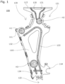
FIG. 1 is an overall view of a chainguide assembly frame 100 according to one embodiment of the present invention; and -
FIG. 2 is an overall view of the chainguide assembly frame 100 according to one embodiment of the present invention mounted to an engine. - A chain
guide assembly frame 100 according to one embodiment of the present invention will be hereinafter described with reference to the drawings. - For ease of explanation,
FIG. 2 does not illustrate the engine, or connection members that connect the engine and theframe 100. - As shown in
FIG. 1 , the chainguide assembly frame 100 includes amain body 110, atop guide 115 provided on the upper surface of themain body 110, afixed chain guide 111 provided on one side face of themain body 110, and a pivoting chainguide holding portion 114 to which apivoting chain guide 112 can be attached on a side face of themain body 110 opposite from thefixed chain guide 111. A fixed-guide-sidesprocket holding portion 120 is provided in an upper part of themain body 110 on the same side as thefixed chain guide 111, and a pivoting-guide-sidesprocket holding portion 121 is provided in an upper part of themain body 110 on the same side as the pivoting chainguide holding portion 114. A drivesprocket holding portion 122 that can hold a drive sprocket DS is provided in a lower part of themain body 110. - Mounting holes H1, H2, H3 used when fixing the frame to an engine (not shown) are provided in various parts of the
main body 110. - An oil passage including a fixed-guide-side
upper oil passage 130 and a pivoting-guide-sideupper oil passage 131 is formed in a vertically extending weld bead shape, i.e., convex on one side of themain body 110 and concave on the other side, each extending from near thetop guide 115 between the fixed-guide-sidesprocket holding portion 120 and the pivoting-guide-sidesprocket holding portion 121 as far as to near the mounting hole H2. - Below the mounting hole H2 are provided a fixed-guide-side
lower oil passage 132 that is an oil passage extending from near the mounting hole H2 gradually downward and toward thefixed chain guide 111, and a pivoting-guide-sidelower oil passage 133 that is an oil passage extending from near the mounting hole H2 gradually downward as far as to near the drivesprocket holding portion 122, passing on the side of the pivoting chainguide holding portion 114 of themain body 110. The fixed-guide-sidelower oil passage 132 and pivoting-guide-sidelower oil passage 133 are connected at their tops near the mounting hole H2. - An
auxiliary oil passage 134 that is an oil passage running parallel to a lower part of the pivoting-guide-sidelower oil passage 133 is formed below the mounting hole H3. - The fixed-guide-side
lower oil passage 132, pivoting-guide-sidelower oil passage 133, andauxiliary oil passage 134 are formed as weld beads similarly to the fixed-guide-sideupper oil passage 130 and pivoting-guide-sideupper oil passage 131. - Since the fixed-guide-side
upper oil passage 130, pivoting-guide-sideupper oil passage 131, fixed-guide-sidelower oil passage 132, pivoting-guide-sidelower oil passage 133 andauxiliary oil passage 134 are formed as weld beads as described above, they can help minimize deflection of themain body 110 and increase the strength. - Next, how oil EL is guided in the chain
guide assembly frame 100 according to one embodiment of the present invention will be described with reference toFIG. 2 . - As shown in
FIG. 2 , the chainguide assembly frame 100 holds a driven sprocket S1 in the fixed-guide-sidesprocket holding portion 120, holds a driven sprocket S2 in the pivoting-guide-sidesprocket holding portion 121, and holds a drive sprocket DS in the drivesprocket holding portion 122. A chain CH is passed around the driven sprockets S1 and S2, and drive sprocket DS. - The pivoting
chain guide 112 is pivotably connected to the pivoting chainguide holding portion 114 via apivot shaft 113, to press the chain CH and create a predetermined tension in the chain CH. - The chain CH is passed around such as to make sliding contact with the
fixed chain guide 111, pivotingchain guide 112, andtop guide 115. - The chain
guide assembly frame 100 is attached to the engine (not shown) via the mounting holes H1, H2, and H3 in this state. - Oil EL is supplied to the chain guide assembly attached to the engine (not shown) for lubricating the chain CH and various parts of the chain guide assembly. Some of the oil EL, squirted when supplied to the chain guide assembly, or scattered by spinning driven sprockets S1 and S2 or drive sprocket DS, or splashing from the running chain CH in sliding contact with the
fixed chain guide 111, pivotingchain guide 112, andtop guide 115, directly adheres to themain body 110. Some of the oil EL in mist form floating around theframe 100 of the chain guide assembly also adheres to themain body 110. - While it depends on from where the oil EL is supplied, the oil EL generally adheres more in upper parts of the
main body 110 and flows down slowly along themain body 110. - Since the fixed-guide-side
upper oil passage 130 and pivoting-guide-sideupper oil passage 131 are provided in upper parts of themain body 110, theoil EL 1 that adhered around the fixed-guide-sidesprocket holding portion 120 near thetop guide 115 is collected in the fixed-guide-sideupper oil passage 130. Theoil EL 2 that adhered around the pivoting-guide-sidesprocket holding portion 121 near thetop guide 115 is collected in the pivoting-guide-sideupper oil passage 131. Theoil EL 1 andEL 2, after traveling along the respective weld bead shapes of the fixed-guide-sideupper oil passage 130 and pivoting-guide-sideupper oil passage 131 and reaching the lower ends, flows down from the respective oil passages. - The fixed-guide-side
upper oil passage 130 and pivoting-guide-sideupper oil passage 131 have their respective upper ends positioned closer to the fixed-guide-sidesprocket holding portion 120 and pivoting-guide-sidesprocket holding portion 121, and lower ends positioned closer to the center of themain body 110. Therefore,oil EL 1 andEL 2 that adhered to themain body 110 above the fixed-guide-sideupper oil passage 130 and pivoting-guide-sideupper oil passage 131 can be efficiently collected from a wide area. - The
oil EL 1 andEL 2 that flowed down from the respective lower ends of the fixed-guide-sideupper oil passage 130 and pivoting-guide-sideupper oil passage 131 is collected respectively in the fixed-guide-sidelower oil passage 132 and pivoting-guide-sidelower oil passage 133, and flows down from the lower ends along the weld bead shapes of the fixed-guide-sidelower oil passage 132 and pivoting-guide-sidelower oil passage 133. - Since the lower end of the fixed-guide-side
lower oil passage 132 is positioned above the fixedchain guide 111, theoil EL 1 collected from around thetop guide 115 is supplied to the fixedchain guide 111, whereby the slidability of the chain CH on thefixed chain guide 111 can be more improved. - Since the lower end of the pivoting-guide-side
lower oil passage 133 is positioned directly above the drivesprocket holding portion 122, theoil EL 2 collected from around thetop guide 115 is supplied to the drive sprocket DS. The drive sprocket DS can thus be lubricated in an efficient manner, and theoil EL 2 can be further supplied to the chain CH via the drive sprocket DS. - The pivoting-guide-side
lower oil passage 133 extends along themain body 110 on the side of the pivoting chainguide holding portion 114 down to directly above the drivesprocket holding portion 122 and is not configured to collect oil EL 3 that adhered above the mounting hole H3 of themain body 110. However, theauxiliary oil passage 134 is formed below the mounting hole H3 so that the oil EL 3 is collected in theauxiliary oil passage 134. - Since the lower end of the
auxiliary oil passage 134 is positioned directly above the drivesprocket holding portion 122, the oil EL 3 is also supplied to the drive sprocket DS. The drive sprocket DS can thus be lubricated more efficiently. - The oil EL that adhered to the
main body 110 is collected in this way by the fixed-guide-sideupper oil passage 130, pivoting-guide-sideupper oil passage 131, fixed-guide-sidelower oil passage 132, pivoting-guide-sidelower oil passage 133, andauxiliary oil passage 134, and guided to predetermined locations. Therefore, various parts such as the chain CH and drive sprocket DS can be efficiently lubricated using a reduced amount of oil EL as compared to the case in which no oil passages are provided. - While one embodiment of the present invention has been described in detail, the present invention is not limited to the embodiment described above and may be carried out with various design changes without departing from the scope of the present invention set forth in the claims.
- In the above-described embodiment, a fixed-guide-side upper oil passage and a pivoting-guide-side upper oil passage are formed in an upper part of the main body. The configuration of the oil passages to be provided in an upper part of the main body is not limited to this example. A fixed-guide-side upper oil passage and a pivoting-guide-side upper oil passage may be formed such as to merge on their way down, for example. One oil passage extending from an upper part of the main body may split into a fixed-guide-side upper oil passage and a pivoting-guide-side upper oil passage somewhere along the way down. Alternatively, the main body may be formed with only one oil passage.
- In the above-described embodiment, a fixed-guide-side lower oil passage and a pivoting-guide-side lower oil passage are formed below the fixed-guide-side upper oil passage and pivoting-guide-side upper oil passage, and the upper ends of the fixed-guide-side lower oil passage and pivoting-guide-side lower oil passage are joined together. The configurations of the fixed-guide-side lower oil passage and pivoting-guide-side lower oil passage are not limited to this example. The fixed-guide-side lower oil passage and pivoting-guide-side lower oil passage may not be joined together, for example. There may be no fixed-guide-side lower oil passage or pivoting-guide-side lower oil passage. Alternatively, the lower end of the fixed-guide-side upper oil passage may be connected to the upper end of the fixed-guide-side lower oil passage.
- In the above-described embodiment, the lower end of the fixed-guide-side lower oil passage is positioned above the fixed chain guide. The fixed-guide-side lower oil passage may have its lower end positioned anywhere, below the fixed chain guide for example, or directly above the mounting hole H3.
- In the above-described embodiment, the lower end of the pivoting-guide-side lower oil passage is positioned directly above the drive sprocket holding portion. The pivoting-guide-side lower oil passage may have its lower end positioned anywhere, directly above the pivoting chain guide holding portion for example, or, the pivoting-guide-side lower oil passage may diverge somewhere to have lower ends, one directly above the pivoting chain guide holding portion and the other directly above the drive sprocket holding portion.
- While an auxiliary oil passage is formed below the mounting hole H3 in the above-described embodiment, the configuration of the auxiliary oil passage is not limited to this example. There may be no auxiliary oil passage for example, or an auxiliary oil passage may be formed above the mounting hole H3 such that its lower end merges with the pivoting-guide-side lower oil passage.
- While a top guide is provided at the top of the main body in the above-described embodiment, the frame configuration of the chain guide assembly is not limited to this example. The top guide may be omitted, for example.
- While the oil passages described in the embodiment above are formed in a weld bead shape, the configuration of the oil passages is not limited to this example. The oil passages may be formed as grooves that are concave on both sides of the main body, for example, or as ridges protruding from both sides of the main body. Alternatively, the oil passages may be formed only on one side of the main body.
Claims (9)
- A chain guide assembly frame comprising a main body and a driven sprocket holding portion that clamps a driven sprocket in an upper part of the main body,the main body including a fixed chain guide, and a pivoting chain guide holding portion to which a pivoting chain guide is mountable,the driven sprocket holding portion including a fixed-guide-side sprocket holding portion provided on a fixed chain guide side, and a pivoting-guide-side sprocket holding portion provided on a pivoting chain guide holding portion side,the main body including a drive sprocket holding portion holding a drive sprocket and located lower than the driven sprocket holding portion,the main body including a concave and/or convex oil passage extending from an upper part toward a lower part to guide oil toward above the drive sprocket holding portion.
- The chain guide assembly frame according to claim 1, wherein the oil passage, at a lower end thereof on a drive sprocket holding portion side, diverges into a fixed-guide-side oil passage formed extending toward the fixed chain guide and a pivoting-guide-side oil passage formed extending toward the pivoting chain guide holding portion.
- The chain guide assembly frame according to claim 1 or 2, whereinthe main body includes, in an upper part thereof, a top guide provided, andthe oil passage includes an upper oil passage formed extending from the top guide through between the fixed-guide-side sprocket holding portion and the pivoting-guide-side sprocket holding portion, and a lower oil passage formed at a position lower than the upper oil passage.
- The chain guide assembly frame according to claim 3, wherein the upper oil passage has a lower end formed to be positioned directly above a topmost part of the lower oil passage.
- The chain guide assembly frame according to claim 3, whereinthe lower oil passage includes a fixed-guide-side lower oil passage formed extending toward the fixed chain guide, and a pivoting-guide-side lower oil passage formed extending toward the pivoting chain guide holding portion, andthe upper oil passage diverges to have a lower end to be positioned directly above the fixed-guide-side lower oil passage and a lower end to be positioned directly above the pivoting-guide-side lower oil passage.
- The chain guide assembly frame according to any one of claims 3 to 5, wherein the upper oil passage includes a fixed-guide-side upper oil passage formed on a fixed-guide-side sprocket holding portion side, and a pivoting-guide-side upper oil passage formed on a pivoting-guide-side sprocket holding portion side.
- The chain guide assembly frame according to claim 6, whereinthe fixed-guide-side upper oil passage has a lower end formed to be positioned directly above the fixed-guide-side lower oil passage, andthe pivoting-guide-side upper oil passage has a lower end formed to be positioned directly above the pivoting-guide-side lower oil passage.
- The chain guide assembly frame according to any one of claims 2 to 7, wherein the pivoting-guide-side oil passage has a lower end formed to be positioned directly above the drive sprocket holding portion.
- The chain guide assembly frame according to any one of claims 1 to 8, wherein the oil passage is formed in a weld bead shape.
Applications Claiming Priority (1)
| Application Number | Priority Date | Filing Date | Title |
|---|---|---|---|
| JP2021205914A JP7719367B2 (en) | 2021-12-20 | 2021-12-20 | Chain guide mechanism frame |
Publications (2)
| Publication Number | Publication Date |
|---|---|
| EP4198347A1 true EP4198347A1 (en) | 2023-06-21 |
| EP4198347B1 EP4198347B1 (en) | 2025-07-23 |
Family
ID=84537904
Family Applications (1)
| Application Number | Title | Priority Date | Filing Date |
|---|---|---|---|
| EP22214584.9A Active EP4198347B1 (en) | 2021-12-20 | 2022-12-19 | Chain guide assembly frame |
Country Status (5)
| Country | Link |
|---|---|
| US (1) | US11933400B2 (en) |
| EP (1) | EP4198347B1 (en) |
| JP (1) | JP7719367B2 (en) |
| KR (1) | KR20230094167A (en) |
| CN (1) | CN116292791A (en) |
Families Citing this family (2)
| Publication number | Priority date | Publication date | Assignee | Title |
|---|---|---|---|---|
| JP7730022B2 (en) * | 2021-12-15 | 2025-08-27 | 株式会社椿本チエイン | Chain guide mechanism frame |
| JP7801574B2 (en) * | 2022-03-24 | 2026-01-19 | 株式会社椿本チエイン | Chain guides, chain transmissions, and transmission systems |
Citations (5)
| Publication number | Priority date | Publication date | Assignee | Title |
|---|---|---|---|---|
| US4607601A (en) * | 1984-02-23 | 1986-08-26 | Compagnie Des Transmissions Mechaniques Sedis | Detachable timing gear cassette unit for an explosion or internal combustion engine |
| JPH08200088A (en) * | 1995-01-20 | 1996-08-06 | Suzuki Motor Corp | Chain case structure of internal combustion engine |
| US20040149250A1 (en) * | 2001-02-17 | 2004-08-05 | Werner Gschwindt | Internal combustion engine comprising a cylinder crankcase |
| JP2006070758A (en) * | 2004-08-31 | 2006-03-16 | Aichi Mach Ind Co Ltd | Internal combustion engine |
| JP2009036273A (en) | 2007-07-31 | 2009-02-19 | Tsubakimoto Chain Co | Tensioner lever |
Family Cites Families (35)
| Publication number | Priority date | Publication date | Assignee | Title |
|---|---|---|---|---|
| JPS5773330U (en) * | 1980-10-23 | 1982-05-06 | ||
| US4741299A (en) * | 1985-01-26 | 1988-05-03 | Honda Giken Kogyo Kabushiki Kaisha | Internal combustion engine |
| US4869708A (en) * | 1988-04-15 | 1989-09-26 | Borg-Warner Transmission And Engine Components Corporation | Sprocket retention/chain guide assembly |
| DE29621831U1 (en) * | 1996-12-16 | 1998-04-16 | Joh Winklhofer & Soehne Gmbh U | Pre-assembled traction drive unit |
| JPH11230281A (en) * | 1998-02-10 | 1999-08-27 | Honda Motor Co Ltd | Tensioner mounting structure |
| JP3778404B2 (en) * | 1998-12-29 | 2006-05-24 | スズキ株式会社 | Engine hydraulic control valve mounting structure |
| JP3640348B2 (en) * | 2001-05-17 | 2005-04-20 | 本田技研工業株式会社 | Cylinder head structure |
| DE20120656U1 (en) * | 2001-12-20 | 2003-04-30 | Joh. Winklhofer & Söhne GmbH und Co. KG, 81369 München | Pre-assembled propellant unit |
| DE20207186U1 (en) * | 2002-05-07 | 2003-09-18 | Joh. Winklhofer & Söhne GmbH und Co KG, 81369 München | Pre-assembled propellant unit with assembly aid |
| JP3954941B2 (en) * | 2002-09-11 | 2007-08-08 | 本田技研工業株式会社 | Oil passage structure in the engine |
| US20050130776A1 (en) * | 2003-12-11 | 2005-06-16 | Borgwarner Inc. | Cassette for securing shipping and assembly of a camshaft drive and timing system |
| JP2009036723A (en) | 2007-08-03 | 2009-02-19 | Olympus Corp | Automatic analysis apparatus and operation environment setting method |
| DE102008020741A1 (en) * | 2007-10-26 | 2009-04-30 | Schaeffler Kg | Module for a traction drive concept |
| US20090186725A1 (en) * | 2008-01-18 | 2009-07-23 | Joseph Jouraij | Multi-utility camshaft cap for internal combustion engine |
| JP4525759B2 (en) * | 2008-01-25 | 2010-08-18 | トヨタ自動車株式会社 | Chain cover for internal combustion engine |
| JP2009185610A (en) * | 2008-02-01 | 2009-08-20 | Toyota Motor Corp | Structure of oil drain passage |
| JP5435279B2 (en) * | 2010-02-15 | 2014-03-05 | スズキ株式会社 | Engine with variable valve timing mechanism |
| US8353268B2 (en) * | 2010-05-17 | 2013-01-15 | GM Global Technology Operations LLC | Oiling system for timing chains |
| US8714124B2 (en) * | 2011-11-25 | 2014-05-06 | Honda Motor Co., Ltd. | Cover structure for internal combustion engine |
| JP5566989B2 (en) * | 2011-11-25 | 2014-08-06 | 本田技研工業株式会社 | Cover structure of internal combustion engine |
| JP2014227928A (en) * | 2013-05-23 | 2014-12-08 | ヤマハ発動機株式会社 | Internal combustion engine, and motor cycle with the same |
| JP6408501B2 (en) * | 2016-03-07 | 2018-10-17 | トヨタ自動車株式会社 | Endless transmission member case |
| JP6432564B2 (en) * | 2016-07-08 | 2018-12-05 | トヨタ自動車株式会社 | Lubricating oil supply device for internal combustion engine chain |
| JP6612465B2 (en) * | 2016-09-27 | 2019-11-27 | 本田技研工業株式会社 | Internal combustion engine |
| JP6487960B2 (en) * | 2017-03-30 | 2019-03-20 | 本田技研工業株式会社 | Internal combustion engine for saddle-ride type vehicles |
| JP6906840B2 (en) * | 2017-04-07 | 2021-07-21 | 株式会社椿本チエイン | Chain guide mechanism |
| DE102018109239B4 (en) * | 2018-04-18 | 2019-10-31 | Schaeffler Technologies AG & Co. KG | Transportable traction drive system for an internal combustion engine |
| JP7107054B2 (en) * | 2018-07-20 | 2022-07-27 | スズキ株式会社 | Internal combustion engine cover structure |
| JP7035880B2 (en) * | 2018-07-25 | 2022-03-15 | トヨタ自動車株式会社 | Internal combustion engine |
| DE102018117985A1 (en) * | 2018-07-25 | 2020-01-30 | Schaeffler Technologies AG & Co. KG | Transportable traction drive system for an internal combustion engine |
| DE102018129532B3 (en) * | 2018-10-26 | 2019-12-19 | Schaeffler Technologies AG & Co. KG | Transportable traction drive system for an internal combustion engine |
| DE102018130732A1 (en) * | 2018-11-23 | 2020-05-28 | Iwis Motorsysteme Gmbh & Co. Kg | Assembly module with hook element |
| DE102019219725B4 (en) * | 2019-12-16 | 2021-07-01 | Psa Automobiles Sa | Mounting bracket for moving components remaining in the combustion engine |
| JP7525791B2 (en) * | 2021-01-15 | 2024-07-31 | 株式会社椿本チエイン | Chain guide mechanism |
| JP7730022B2 (en) * | 2021-12-15 | 2025-08-27 | 株式会社椿本チエイン | Chain guide mechanism frame |
-
2021
- 2021-12-20 JP JP2021205914A patent/JP7719367B2/en active Active
-
2022
- 2022-12-08 CN CN202211570589.XA patent/CN116292791A/en active Pending
- 2022-12-13 US US18/080,261 patent/US11933400B2/en active Active
- 2022-12-19 EP EP22214584.9A patent/EP4198347B1/en active Active
- 2022-12-19 KR KR1020220178240A patent/KR20230094167A/en active Pending
Patent Citations (5)
| Publication number | Priority date | Publication date | Assignee | Title |
|---|---|---|---|---|
| US4607601A (en) * | 1984-02-23 | 1986-08-26 | Compagnie Des Transmissions Mechaniques Sedis | Detachable timing gear cassette unit for an explosion or internal combustion engine |
| JPH08200088A (en) * | 1995-01-20 | 1996-08-06 | Suzuki Motor Corp | Chain case structure of internal combustion engine |
| US20040149250A1 (en) * | 2001-02-17 | 2004-08-05 | Werner Gschwindt | Internal combustion engine comprising a cylinder crankcase |
| JP2006070758A (en) * | 2004-08-31 | 2006-03-16 | Aichi Mach Ind Co Ltd | Internal combustion engine |
| JP2009036273A (en) | 2007-07-31 | 2009-02-19 | Tsubakimoto Chain Co | Tensioner lever |
Also Published As
| Publication number | Publication date |
|---|---|
| JP7719367B2 (en) | 2025-08-06 |
| EP4198347B1 (en) | 2025-07-23 |
| US11933400B2 (en) | 2024-03-19 |
| KR20230094167A (en) | 2023-06-27 |
| US20230193795A1 (en) | 2023-06-22 |
| JP2023091262A (en) | 2023-06-30 |
| CN116292791A (en) | 2023-06-23 |
Similar Documents
| Publication | Publication Date | Title |
|---|---|---|
| US11933400B2 (en) | Chain guide assembly frame | |
| US8696500B2 (en) | Tensioner lever | |
| KR102873405B1 (en) | Chain guide | |
| CA2047048C (en) | High load force transmission belt | |
| EP1300608A2 (en) | Movable lever for transmission chain | |
| US5960902A (en) | Motorcycle swing arm assembly with removable spacer | |
| EP1368583B1 (en) | Inner race idler pulley tensioner | |
| GB2397862A (en) | Movable guide for transmission device | |
| KR101702930B1 (en) | Chain guide mechanism | |
| US6849013B2 (en) | Sliding contact guide for transmission device | |
| EP3095568A1 (en) | Chainsaw guide bar nose assembly | |
| JP2003214504A (en) | Movable lever for transmission chain | |
| JPS63282018A (en) | Lubricating method for driving chain for tenter clip | |
| JPH0932573A (en) | Chain guide structure | |
| CN223648462U (en) | Mute toothed chain transmission system of motorcycle | |
| CN219150839U (en) | Fruit and vegetable sorting machine and chain lubricating device thereof | |
| CN216580757U (en) | Antiwear self-lubricating chain link for track | |
| US11927267B2 (en) | Chain guide and chain transmission device using same | |
| JP2002115750A (en) | Timing chain guide | |
| JPS6212155Y2 (en) | ||
| JP2011220456A (en) | Chain guide mechanism | |
| JPS6019932Y2 (en) | Engine oil distribution system | |
| JP2981981B2 (en) | Rear wheel suspension for vehicles | |
| EP0429384A1 (en) | Device for automatic lubrication of the universal joint of the transmission | |
| JPH07115818B2 (en) | Man conveyor tread support device |
Legal Events
| Date | Code | Title | Description |
|---|---|---|---|
| PUAI | Public reference made under article 153(3) epc to a published international application that has entered the european phase |
Free format text: ORIGINAL CODE: 0009012 |
|
| STAA | Information on the status of an ep patent application or granted ep patent |
Free format text: STATUS: THE APPLICATION HAS BEEN PUBLISHED |
|
| AK | Designated contracting states |
Kind code of ref document: A1 Designated state(s): AL AT BE BG CH CY CZ DE DK EE ES FI FR GB GR HR HU IE IS IT LI LT LU LV MC ME MK MT NL NO PL PT RO RS SE SI SK SM TR |
|
| STAA | Information on the status of an ep patent application or granted ep patent |
Free format text: STATUS: REQUEST FOR EXAMINATION WAS MADE |
|
| 17P | Request for examination filed |
Effective date: 20230905 |
|
| RBV | Designated contracting states (corrected) |
Designated state(s): AL AT BE BG CH CY CZ DE DK EE ES FI FR GB GR HR HU IE IS IT LI LT LU LV MC ME MK MT NL NO PL PT RO RS SE SI SK SM TR |
|
| STAA | Information on the status of an ep patent application or granted ep patent |
Free format text: STATUS: EXAMINATION IS IN PROGRESS |
|
| 17Q | First examination report despatched |
Effective date: 20240318 |
|
| GRAP | Despatch of communication of intention to grant a patent |
Free format text: ORIGINAL CODE: EPIDOSNIGR1 |
|
| STAA | Information on the status of an ep patent application or granted ep patent |
Free format text: STATUS: GRANT OF PATENT IS INTENDED |
|
| RIC1 | Information provided on ipc code assigned before grant |
Ipc: F02F 7/00 20060101ALN20250210BHEP Ipc: F01L 1/02 20060101ALI20250210BHEP Ipc: F16H 57/04 20100101ALI20250210BHEP Ipc: F16H 7/18 20060101ALI20250210BHEP Ipc: F16H 7/08 20060101AFI20250210BHEP |
|
| INTG | Intention to grant announced |
Effective date: 20250219 |
|
| GRAS | Grant fee paid |
Free format text: ORIGINAL CODE: EPIDOSNIGR3 |
|
| GRAA | (expected) grant |
Free format text: ORIGINAL CODE: 0009210 |
|
| STAA | Information on the status of an ep patent application or granted ep patent |
Free format text: STATUS: THE PATENT HAS BEEN GRANTED |
|
| AK | Designated contracting states |
Kind code of ref document: B1 Designated state(s): AL AT BE BG CH CY CZ DE DK EE ES FI FR GB GR HR HU IE IS IT LI LT LU LV MC ME MK MT NL NO PL PT RO RS SE SI SK SM TR |
|
| REG | Reference to a national code |
Ref country code: GB Ref legal event code: FG4D |
|
| REG | Reference to a national code |
Ref country code: CH Ref legal event code: EP |
|
| REG | Reference to a national code |
Ref country code: IE Ref legal event code: FG4D |
|
| REG | Reference to a national code |
Ref country code: DE Ref legal event code: R096 Ref document number: 602022018005 Country of ref document: DE |
|
| REG | Reference to a national code |
Ref country code: NL Ref legal event code: MP Effective date: 20250723 |
|
| PG25 | Lapsed in a contracting state [announced via postgrant information from national office to epo] |
Ref country code: PT Free format text: LAPSE BECAUSE OF FAILURE TO SUBMIT A TRANSLATION OF THE DESCRIPTION OR TO PAY THE FEE WITHIN THE PRESCRIBED TIME-LIMIT Effective date: 20251124 |
|
| PG25 | Lapsed in a contracting state [announced via postgrant information from national office to epo] |
Ref country code: NL Free format text: LAPSE BECAUSE OF FAILURE TO SUBMIT A TRANSLATION OF THE DESCRIPTION OR TO PAY THE FEE WITHIN THE PRESCRIBED TIME-LIMIT Effective date: 20250723 |
|
| REG | Reference to a national code |
Ref country code: AT Ref legal event code: MK05 Ref document number: 1816714 Country of ref document: AT Kind code of ref document: T Effective date: 20250723 |
|
| PG25 | Lapsed in a contracting state [announced via postgrant information from national office to epo] |
Ref country code: IS Free format text: LAPSE BECAUSE OF FAILURE TO SUBMIT A TRANSLATION OF THE DESCRIPTION OR TO PAY THE FEE WITHIN THE PRESCRIBED TIME-LIMIT Effective date: 20251123 |
|
| PGFP | Annual fee paid to national office [announced via postgrant information from national office to epo] |
Ref country code: DE Payment date: 20251028 Year of fee payment: 4 |
|
| PG25 | Lapsed in a contracting state [announced via postgrant information from national office to epo] |
Ref country code: NO Free format text: LAPSE BECAUSE OF FAILURE TO SUBMIT A TRANSLATION OF THE DESCRIPTION OR TO PAY THE FEE WITHIN THE PRESCRIBED TIME-LIMIT Effective date: 20251023 |
|
| REG | Reference to a national code |
Ref country code: LT Ref legal event code: MG9D |
|
| PG25 | Lapsed in a contracting state [announced via postgrant information from national office to epo] |
Ref country code: AT Free format text: LAPSE BECAUSE OF FAILURE TO SUBMIT A TRANSLATION OF THE DESCRIPTION OR TO PAY THE FEE WITHIN THE PRESCRIBED TIME-LIMIT Effective date: 20250723 |
|
| PG25 | Lapsed in a contracting state [announced via postgrant information from national office to epo] |
Ref country code: FI Free format text: LAPSE BECAUSE OF FAILURE TO SUBMIT A TRANSLATION OF THE DESCRIPTION OR TO PAY THE FEE WITHIN THE PRESCRIBED TIME-LIMIT Effective date: 20250723 |
|
| PG25 | Lapsed in a contracting state [announced via postgrant information from national office to epo] |
Ref country code: HR Free format text: LAPSE BECAUSE OF FAILURE TO SUBMIT A TRANSLATION OF THE DESCRIPTION OR TO PAY THE FEE WITHIN THE PRESCRIBED TIME-LIMIT Effective date: 20250723 |
|
| PGFP | Annual fee paid to national office [announced via postgrant information from national office to epo] |
Ref country code: FR Payment date: 20251110 Year of fee payment: 4 |
|
| PG25 | Lapsed in a contracting state [announced via postgrant information from national office to epo] |
Ref country code: GR Free format text: LAPSE BECAUSE OF FAILURE TO SUBMIT A TRANSLATION OF THE DESCRIPTION OR TO PAY THE FEE WITHIN THE PRESCRIBED TIME-LIMIT Effective date: 20251024 |
|
| PG25 | Lapsed in a contracting state [announced via postgrant information from national office to epo] |
Ref country code: SE Free format text: LAPSE BECAUSE OF FAILURE TO SUBMIT A TRANSLATION OF THE DESCRIPTION OR TO PAY THE FEE WITHIN THE PRESCRIBED TIME-LIMIT Effective date: 20250723 |
|
| PG25 | Lapsed in a contracting state [announced via postgrant information from national office to epo] |
Ref country code: LV Free format text: LAPSE BECAUSE OF FAILURE TO SUBMIT A TRANSLATION OF THE DESCRIPTION OR TO PAY THE FEE WITHIN THE PRESCRIBED TIME-LIMIT Effective date: 20250723 |
|
| PG25 | Lapsed in a contracting state [announced via postgrant information from national office to epo] |
Ref country code: PL Free format text: LAPSE BECAUSE OF FAILURE TO SUBMIT A TRANSLATION OF THE DESCRIPTION OR TO PAY THE FEE WITHIN THE PRESCRIBED TIME-LIMIT Effective date: 20250723 Ref country code: BG Free format text: LAPSE BECAUSE OF FAILURE TO SUBMIT A TRANSLATION OF THE DESCRIPTION OR TO PAY THE FEE WITHIN THE PRESCRIBED TIME-LIMIT Effective date: 20250723 |
|
| PG25 | Lapsed in a contracting state [announced via postgrant information from national office to epo] |
Ref country code: RS Free format text: LAPSE BECAUSE OF FAILURE TO SUBMIT A TRANSLATION OF THE DESCRIPTION OR TO PAY THE FEE WITHIN THE PRESCRIBED TIME-LIMIT Effective date: 20251023 |
|
| PG25 | Lapsed in a contracting state [announced via postgrant information from national office to epo] |
Ref country code: ES Free format text: LAPSE BECAUSE OF FAILURE TO SUBMIT A TRANSLATION OF THE DESCRIPTION OR TO PAY THE FEE WITHIN THE PRESCRIBED TIME-LIMIT Effective date: 20250723 |
|
| PG25 | Lapsed in a contracting state [announced via postgrant information from national office to epo] |
Ref country code: RO Free format text: LAPSE BECAUSE OF FAILURE TO SUBMIT A TRANSLATION OF THE DESCRIPTION OR TO PAY THE FEE WITHIN THE PRESCRIBED TIME-LIMIT Effective date: 20250723 |
|
| PG25 | Lapsed in a contracting state [announced via postgrant information from national office to epo] |
Ref country code: SM Free format text: LAPSE BECAUSE OF FAILURE TO SUBMIT A TRANSLATION OF THE DESCRIPTION OR TO PAY THE FEE WITHIN THE PRESCRIBED TIME-LIMIT Effective date: 20250723 |
|
| PG25 | Lapsed in a contracting state [announced via postgrant information from national office to epo] |
Ref country code: DK Free format text: LAPSE BECAUSE OF FAILURE TO SUBMIT A TRANSLATION OF THE DESCRIPTION OR TO PAY THE FEE WITHIN THE PRESCRIBED TIME-LIMIT Effective date: 20250723 |
|
| PG25 | Lapsed in a contracting state [announced via postgrant information from national office to epo] |
Ref country code: IT Free format text: LAPSE BECAUSE OF FAILURE TO SUBMIT A TRANSLATION OF THE DESCRIPTION OR TO PAY THE FEE WITHIN THE PRESCRIBED TIME-LIMIT Effective date: 20250723 |
|
| PG25 | Lapsed in a contracting state [announced via postgrant information from national office to epo] |
Ref country code: CZ Free format text: LAPSE BECAUSE OF FAILURE TO SUBMIT A TRANSLATION OF THE DESCRIPTION OR TO PAY THE FEE WITHIN THE PRESCRIBED TIME-LIMIT Effective date: 20250723 |
|
| PG25 | Lapsed in a contracting state [announced via postgrant information from national office to epo] |
Ref country code: SK Free format text: LAPSE BECAUSE OF FAILURE TO SUBMIT A TRANSLATION OF THE DESCRIPTION OR TO PAY THE FEE WITHIN THE PRESCRIBED TIME-LIMIT Effective date: 20250723 Ref country code: EE Free format text: LAPSE BECAUSE OF FAILURE TO SUBMIT A TRANSLATION OF THE DESCRIPTION OR TO PAY THE FEE WITHIN THE PRESCRIBED TIME-LIMIT Effective date: 20250723 |