EP4197879A1 - Punktartiges zugsteuerungs-onboard-system und zugsteuerungsverfahren - Google Patents
Punktartiges zugsteuerungs-onboard-system und zugsteuerungsverfahren Download PDFInfo
- Publication number
- EP4197879A1 EP4197879A1 EP21945605.0A EP21945605A EP4197879A1 EP 4197879 A1 EP4197879 A1 EP 4197879A1 EP 21945605 A EP21945605 A EP 21945605A EP 4197879 A1 EP4197879 A1 EP 4197879A1
- Authority
- EP
- European Patent Office
- Prior art keywords
- module
- onboard
- train
- interface
- communication module
- Prior art date
- Legal status (The legal status is an assumption and is not a legal conclusion. Google has not performed a legal analysis and makes no representation as to the accuracy of the status listed.)
- Granted
Links
Images
Classifications
-
- B—PERFORMING OPERATIONS; TRANSPORTING
- B61—RAILWAYS
- B61L—GUIDING RAILWAY TRAFFIC; ENSURING THE SAFETY OF RAILWAY TRAFFIC
- B61L15/00—Indicators provided on the vehicle or train for signalling purposes
- B61L15/0018—Communication with or on the vehicle or train
-
- B—PERFORMING OPERATIONS; TRANSPORTING
- B60—VEHICLES IN GENERAL
- B60T—VEHICLE BRAKE CONTROL SYSTEMS OR PARTS THEREOF; BRAKE CONTROL SYSTEMS OR PARTS THEREOF, IN GENERAL; ARRANGEMENT OF BRAKING ELEMENTS ON VEHICLES IN GENERAL; PORTABLE DEVICES FOR PREVENTING UNWANTED MOVEMENT OF VEHICLES; VEHICLE MODIFICATIONS TO FACILITATE COOLING OF BRAKES
- B60T13/00—Transmitting braking action from initiating means to ultimate brake actuator with power assistance or drive; Brake systems incorporating such transmitting means, e.g. air-pressure brake systems
- B60T13/10—Transmitting braking action from initiating means to ultimate brake actuator with power assistance or drive; Brake systems incorporating such transmitting means, e.g. air-pressure brake systems with fluid assistance, drive, or release
- B60T13/66—Electrical control in fluid-pressure brake systems
- B60T13/665—Electrical control in fluid-pressure brake systems the systems being specially adapted for transferring two or more command signals, e.g. railway systems
-
- B—PERFORMING OPERATIONS; TRANSPORTING
- B60—VEHICLES IN GENERAL
- B60T—VEHICLE BRAKE CONTROL SYSTEMS OR PARTS THEREOF; BRAKE CONTROL SYSTEMS OR PARTS THEREOF, IN GENERAL; ARRANGEMENT OF BRAKING ELEMENTS ON VEHICLES IN GENERAL; PORTABLE DEVICES FOR PREVENTING UNWANTED MOVEMENT OF VEHICLES; VEHICLE MODIFICATIONS TO FACILITATE COOLING OF BRAKES
- B60T17/00—Component parts, details, or accessories of power brake systems not covered by groups B60T8/00, B60T13/00 or B60T15/00, or presenting other characteristic features
- B60T17/18—Safety devices; Monitoring
- B60T17/22—Devices for monitoring or checking brake systems; Signal devices
- B60T17/228—Devices for monitoring or checking brake systems; Signal devices for railway vehicles
-
- B—PERFORMING OPERATIONS; TRANSPORTING
- B61—RAILWAYS
- B61H—BRAKES OR OTHER RETARDING DEVICES SPECIALLY ADAPTED FOR RAIL VEHICLES; ARRANGEMENT OR DISPOSITION THEREOF IN RAIL VEHICLES
- B61H13/00—Actuating rail-vehicle brakes
-
- B—PERFORMING OPERATIONS; TRANSPORTING
- B61—RAILWAYS
- B61L—GUIDING RAILWAY TRAFFIC; ENSURING THE SAFETY OF RAILWAY TRAFFIC
- B61L15/00—Indicators provided on the vehicle or train for signalling purposes
-
- B—PERFORMING OPERATIONS; TRANSPORTING
- B61—RAILWAYS
- B61L—GUIDING RAILWAY TRAFFIC; ENSURING THE SAFETY OF RAILWAY TRAFFIC
- B61L15/00—Indicators provided on the vehicle or train for signalling purposes
- B61L15/0018—Communication with or on the vehicle or train
- B61L15/0036—Conductor-based, e.g. using CAN-Bus, train-line or optical fibres
-
- B—PERFORMING OPERATIONS; TRANSPORTING
- B61—RAILWAYS
- B61L—GUIDING RAILWAY TRAFFIC; ENSURING THE SAFETY OF RAILWAY TRAFFIC
- B61L15/00—Indicators provided on the vehicle or train for signalling purposes
- B61L15/0058—On-board optimisation of vehicle or vehicle train operation
-
- B—PERFORMING OPERATIONS; TRANSPORTING
- B61—RAILWAYS
- B61L—GUIDING RAILWAY TRAFFIC; ENSURING THE SAFETY OF RAILWAY TRAFFIC
- B61L15/00—Indicators provided on the vehicle or train for signalling purposes
- B61L15/0072—On-board train data handling
-
- B—PERFORMING OPERATIONS; TRANSPORTING
- B61—RAILWAYS
- B61L—GUIDING RAILWAY TRAFFIC; ENSURING THE SAFETY OF RAILWAY TRAFFIC
- B61L3/00—Devices along the route for controlling devices on the vehicle or train, e.g. to release brake or to operate a warning signal
- B61L3/02—Devices along the route for controlling devices on the vehicle or train, e.g. to release brake or to operate a warning signal at selected places along the route, e.g. intermittent control simultaneous mechanical and electrical control
- B61L3/08—Devices along the route for controlling devices on the vehicle or train, e.g. to release brake or to operate a warning signal at selected places along the route, e.g. intermittent control simultaneous mechanical and electrical control controlling electrically
- B61L3/12—Devices along the route for controlling devices on the vehicle or train, e.g. to release brake or to operate a warning signal at selected places along the route, e.g. intermittent control simultaneous mechanical and electrical control controlling electrically using magnetic or electrostatic induction; using radio waves
- B61L3/125—Devices along the route for controlling devices on the vehicle or train, e.g. to release brake or to operate a warning signal at selected places along the route, e.g. intermittent control simultaneous mechanical and electrical control controlling electrically using magnetic or electrostatic induction; using radio waves using short-range radio transmission
-
- Y—GENERAL TAGGING OF NEW TECHNOLOGICAL DEVELOPMENTS; GENERAL TAGGING OF CROSS-SECTIONAL TECHNOLOGIES SPANNING OVER SEVERAL SECTIONS OF THE IPC; TECHNICAL SUBJECTS COVERED BY FORMER USPC CROSS-REFERENCE ART COLLECTIONS [XRACs] AND DIGESTS
- Y02—TECHNOLOGIES OR APPLICATIONS FOR MITIGATION OR ADAPTATION AGAINST CLIMATE CHANGE
- Y02T—CLIMATE CHANGE MITIGATION TECHNOLOGIES RELATED TO TRANSPORTATION
- Y02T90/00—Enabling technologies or technologies with a potential or indirect contribution to GHG emissions mitigation
- Y02T90/10—Technologies relating to charging of electric vehicles
- Y02T90/16—Information or communication technologies improving the operation of electric vehicles
Definitions
- the present invention relates to the field of railway signal technologies, and in particular to a point-type onboard system for controlling a train and a train control method.
- the PZB host conveys train supervision speed, speed limit, warning information, and the like by means of DMI display and speaker sound, so as to prompt the driver to drive the train safely and efficiently, and can output emergency braking information and braking control signals according to the comprehensive situation of operation management.
- the signals provided by the host computer for the onboard antenna are switch signals sharing a negative pole, and these signals are not electrically independent.
- the host computer in the existing point-type train control system has a large volume, which is not convenient for integrated mounting of new vehicles.
- the present invention provides a point-type onboard system for controlling a train and a train control method.
- the point-type onboard system for controlling a train in the present invention includes an onboard antenna, a recording module, a logic decoding module, a power amplification module, an interface module, and a communication module, where
- the interface module is provided with two safety AND gate circuits and two onboard relays, where the two safety AND gate circuits respectively connect to the two onboard relays, and the two onboard relays connect to an emergency braking unit of the train.
- the interface module connects to a speed sensor unit of the train through a first interface, the interface module is configured to collect statistics about a quantity of output pulse waveforms of the speed sensor unit, calculate a cycle of a pulse, and report the quantity of the output pulse waveforms and the cycle of the pulse to the communication module.
- the interface module connects to a switch button of a train cab through a second interface.
- the interface module is provided with a dynamic pulse acquiring circuit, where the dynamic pulse acquiring circuit is configured to perform AND gate logic operation on a control pulse sent by the communication module and a level signal acquired from the second interface.
- the interface module is provided with a second dynamic acquiring circuit, where the second dynamic acquiring circuit is configured to reaquire a level signal in a dry contact for requisition of the onboard relay so as to acquire emergency brake output status information of the onboard relay for the communication module.
- the recording module is configured to connect the communication module, logic decoding module, interface module, and power amplification module through diode isolation.
- system further includes an onboard man-machine interface.
- the communication module connects to the onboard man-machine interface.
- the present invention further provides a train control method that is applied to the point-type onboard system for controlling a train and includes at least one of the following steps:
- step A the two CPUs having independent power supplies of the logic decoding module are controlled to transmit, through an isolated serial communication channel, a decoding result of the logic decoding module and compare and check the result.
- step C the two CPUs having independent power supplies of the communication module each output a pulse square wave to the safety AND gate circuit of the interface module, and when neither of the two CPUs having independent power supplies of the communication module outputs the pulse square wave, the safety AND gate circuit of the interface module controls the relay to fall, that is, outputs emergency braking.
- step D CPUs of the communication module, logic decoding module, and interface module are controlled to communicate with each other, an onboard antenna resonance state, speed information, and displacement information are obtained from the logic decoding module, and related information of a level signal outputted by the safety AND gate circuit is acquired.
- the point-type onboard system for controlling a train in the present invention has the functional characteristics of fault self-diagnosis. It can be determined according to the voltage value whether the power amplification module of the host or the onboard antenna fails or is disconnected.
- the diagnostic circuit has double CPUs each having an independent power supply to avoid misjudgment caused by a single fault.
- the system has high security and uses a safety AND gate circuit structure for the output emergency brake, so as to avoid the failure to output the emergency braking due to the failure of the single-channel CPU circuit. Further, the system uses three independent frequency signals to provide signals for the PZB onboard antenna, avoiding the potential safety hazard of fault interference between signals, where the host is small, which is convenient for integrated mounting of new vehicles.
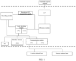
- FIG. 1 is a schematic structural diagram of a point-type onboard system for controlling a train according to an embodiment of the present invention.
- FIG. 1 is a schematic structural diagram of a point-type onboard system for controlling a train according to the present invention.
- the point-type onboard system for controlling a train of the present invention includes a PZB onboard antenna (which can also be referred to as LGP) and a PZB onboard host (which can also be referred to as an onboard host).
- the onboard host includes a recording module, a logic decoding module, a power amplification module, an interface module, and a communication module.
- the logic decoding module is provided with two CPUs having independent power supplies: CPU 3 and CPU 4.
- the communication module is provided with two CPUs having independent power supplies: CPU 1 and CPU 2.
- the interface module is provided with one CPU: CPU 5.
- the point-type onboard system for controlling a train may further include an onboard man-machine interface (DMI). In this case, DMI connects to the communication module.
- DMI man-machine interface
- the communication module connects to the logic decoding module, the recording module, and the recording module, and the interface module connects the logic decoding module to the recording module.
- the recording module connects to the power amplification module and the logic decoding module.
- the power amplification module connects to the LGP.
- the communication module can be connected to an A-series onboard host and a B-series onboard host. The A-series onboard host and the B-series onboard host are mutually redundant.
- the LGP is mounted on the right side of the driving direction of a train.
- the PZB trackside response antenna (which can be also referred to as ground antenna) mounted on the side of the rail, the onboard antenna and the ground antenna form resonance, and the impedance of the onboard antenna increases.
- the power amplification module is used to continuously send three independent sine wave signals for the onboard antenna, the frequencies being 500 Hz, 1000 Hz, 2000 Hz respectively.
- the voltage signal outputted by the power amplification module generates currents of, for example, 270 mAin the three signal loops corresponding to the three frequencies of the onboard antenna.
- the current, in the signal loop outputted by the power amplification module, corresponding to the signal loop of a resonant frequency drops sharply to less than half of the original current value.
- the output current value of the power amplification module (hereinafter referred to as LC current) is converted into voltage information (hereinafter referred to as LC voltage) using a sensor on the power amplification module such as a non-contact current sensor.
- the logic decoding module is configured to provide an enable signal for the power amplification module, the enable signal is active at high level, and the power amplification module outputs LC current only when the enable signal is at high level.
- the power amplification module is provided with a voltage detection terminal.
- the logic decoding module is configured to receive the LC current of the power amplification module, and is also configured to receive the output voltage detection signal of the power amplification module detected from the voltage detection terminal of the power amplification module.
- the logic decoding module is configured to parse the received LC current, and the frequency of the ground antenna through which the train passes is determined if the LC current has dropped and the logic decoding module has identified a frequency corresponding to the dropped LC current.
- the frequency information of the ground antenna represents the position information of the signal light, and nearly half of them can obtain the corresponding displacement information and speed information.
- the logic decoding module is configured to send the received determining signal to the communication module.
- the logic decoding module has two independent CPUs: CPU3 and CPU4, the power supplies of CPU3 and CPU4 being completely independent.
- CPU3 and CPU4 are configured to transmit, through an isolated serial communication channel, a decoding result of the logic decoding module and compare and check the result.
- Each of the three LC currents outputted by the power amplification module is acquired by two independent current sensors such as non-contact current sensors.
- the detection signal outputted by the current sensor is acquired by the respective analog-signal-to-digital-signal (AD) channels of CPU3 and CPU4 of the logic decoding module.
- AD analog-signal-to-digital-signal
- the interface module is provided with two safety AND gate circuits. Under the control of the logic decoding module, the level signals outputted by the two safety AND gate circuits are respectively configured to control the two relays (hereinafter referred to as onboard relays, each onboard relay having one dry contact connected to the emergency braking unit of the train and another dry contact for reacquisition configured to reacquire the level signal outputted by the onboard relay) of the interface module to go up or down.
- the output dry contacts of the two relays of the interface module are configured to connect the emergency braking unit of the train to control the emergency braking of the train.
- the interface module has a first interface connected to a speed sensor unit.
- the interface module collects statistics about a quantity of output pulse waveforms of the speed sensor unit, calculates a cycle of a pulse, and reports the quantity of the output pulse waveforms and the cycle of the pulse to the communication module.
- the communication module sends control pulses to the interface module.
- the interface module has a second interface connected to the switch button of the train cab.
- a dynamic pulse acquiring circuit is also provided on the interface module.
- the dynamic pulse acquiring circuit performs AND gate logic operation on a control pulse sent by the communication module and a level signal acquired from the second interface of the interface module, a result of the AND gate logic operation is acquired by the communication module, and the acquired result is used to identify and avoid continuous misunderstanding that a level signal acquired by the dynamic pulse acquiring circuit has a single level characteristic due to a dynamic pulse acquiring circuit failure.
- the interface module reacquires the level signal in the dry contact for reacquisition of the onboard relay on the interface module through the second dynamic acquiring circuit, such that the second dynamic acquiring circuit acquires the emergency brake (EB) output status information for the communication module.
- EB emergency brake
- the communication module determines whether an onboard relay sticking fault occurs, where the sticking fault occurs when the EB command and the reacquired EB output status information are inconsistent.
- the communication module has an Ethernet communication interface, and the Ethernet interface is connected to the DMI for controlling the output of the DMI: train speed, speed monitoring result, and alarm information, and the like.
- the Ethernet interface is further configured to receive human-computer interaction information such as data input or commands from the DMI.
- the communication module has an interface such as Profibus-DP for communication with a control system such as the European Train Control System (ETCS system).
- ECS system European Train Control System
- the communication module receives the command of ETCS to control the point-type onboard system for controlling a train.
- the communication with ETCS complies with the requirements of STM control state transition and working state transition stipulated in SUBSET-026 and SUBSET-035 in functional requirement specifications of the ETCS train control system.
- the Profibus-DP interface of the communication module can be reserved, or used to output communication data to ETCS equipment or judicial recording unit equipment according to the communication protocol.
- the communication module is provided with two CPUs having independent power supplies: CPU1 and CPU2.
- CPU1 and CPU2 are configured to output the pulse square wave to the safety AND gate circuit of the interface module respectively.
- the safety AND gate circuit of the interface module controls the onboard relay to fall, that is, outputs emergency braking.
- the communication module is configured to communicate with the CPUs of the logic decoding module and the interface module through the controller area network (CAN) bus, to obtain the onboard antenna resonance state (that is, whether it is in resonance), speed information, and displacement information from the logic decoding module, and acquire relevant information such as the level signal outputted by the safety AND gate circuit.
- the communication module is configured to comprehensively process the above information so as to perform the PZB speed monitoring function of assisting the driver in driving.
- the recording module is configured to connect the communication module, logic decoding module, interface module, and power amplification module through diode isolation using the CAN bus.
- the recording module is connected to the universal asynchronous receiver transmitter (UART) serial communication interfaces of the communication module and the logic decoding module for outputting.
- UART universal asynchronous receiver transmitter
- the recording module may be configured to acquire and record the LC voltage signal of the power amplification module and the communication data of each CPU (that is, CPU1-CPU5). Each CPU outputs UART maintenance data.
- the power supply module in the host function device is configured to provide separate power supplies to double CPUs of the communication module, the double CPUs of the logic decoding module, the CPU of the interface module, and the power amplification module so as to output signals to the onboard antenna.
- the input DC of the power module may be 110 V DC or 72 V
- the host function equipment includes a backplane, where the backplane is provided with a plurality of slots, and the slots are used for placing and correspondingly connecting each module in the host function equipment, the connection including direct electrical connections and level connection as well as logic connection to each module.
- the point-type onboard system for controlling a train in the present invention has the functional characteristics of fault self-diagnosis. It can be determined according to the voltage value whether the power amplification module of the host or the onboard antenna fails or is disconnected.
- the diagnostic circuit has double CPUs each having an independent power supply to avoid misjudgment caused by a single fault.
- the system has high security and uses a safety AND gate circuit structure for the output emergency brake, so as to avoid the failure to output the emergency braking due to the failure of the single-channel CPU circuit. Further, the system uses three independent frequency signals to provide signals for the PZB onboard antenna, avoiding the potential safety hazard of fault interference between signals, where the host is small in size, which is convenient for integrated mounting of new vehicles.
Landscapes
- Engineering & Computer Science (AREA)
- Mechanical Engineering (AREA)
- Transportation (AREA)
- Electric Propulsion And Braking For Vehicles (AREA)
- Train Traffic Observation, Control, And Security (AREA)
Applications Claiming Priority (2)
| Application Number | Priority Date | Filing Date | Title |
|---|---|---|---|
| CN202110668889.0A CN113120035B (zh) | 2021-06-17 | 2021-06-17 | 一种点式列车控制车载系统及列车控制方法 |
| PCT/CN2021/105120 WO2022262022A1 (zh) | 2021-06-17 | 2021-07-08 | 一种点式列车控制车载系统及列车控制方法 |
Publications (4)
| Publication Number | Publication Date |
|---|---|
| EP4197879A1 true EP4197879A1 (de) | 2023-06-21 |
| EP4197879A4 EP4197879A4 (de) | 2024-06-05 |
| EP4197879C0 EP4197879C0 (de) | 2026-01-07 |
| EP4197879B1 EP4197879B1 (de) | 2026-01-07 |
Family
ID=76782990
Family Applications (1)
| Application Number | Title | Priority Date | Filing Date |
|---|---|---|---|
| EP21945605.0A Active EP4197879B1 (de) | 2021-06-17 | 2021-07-08 | Punktartiges zugsteuerungs-onboard-system und zugsteuerungsverfahren |
Country Status (3)
| Country | Link |
|---|---|
| EP (1) | EP4197879B1 (de) |
| CN (1) | CN113120035B (de) |
| WO (1) | WO2022262022A1 (de) |
Families Citing this family (1)
| Publication number | Priority date | Publication date | Assignee | Title |
|---|---|---|---|---|
| CN115817579B (zh) * | 2022-12-28 | 2025-12-12 | 通号粤港澳(广州)交通科技有限公司 | 一种有轨电车车载控制系统 |
Family Cites Families (12)
| Publication number | Priority date | Publication date | Assignee | Title |
|---|---|---|---|---|
| DE10302858A1 (de) * | 2003-01-03 | 2004-07-22 | Siemens Ag | System zur induktiven Zugsicherung |
| CN101540656B (zh) * | 2009-04-22 | 2012-05-09 | 深圳市远望谷信息技术股份有限公司 | 用于ctcs点式应答器的解码装置和解码方法 |
| US8200380B2 (en) * | 2009-05-19 | 2012-06-12 | Siemens Industry, Inc. | Method and apparatus for hybrid train control device |
| DE102010025034A1 (de) * | 2010-06-24 | 2011-12-29 | Siemens Aktiengesellschaft | Fahrzeuggerät für ein System zur punktförmigen induktiven Zugbeeinflussung |
| CN102923165B (zh) * | 2011-08-11 | 2015-06-24 | 北京交大思诺科技有限公司 | 集成化列车超速防护车载设备 |
| DE102013226718A1 (de) * | 2013-12-19 | 2015-06-25 | Siemens Aktiengesellschaft | ETCS-Streckenausrüstung |
| CN204978661U (zh) * | 2015-07-03 | 2016-01-20 | 北京交大思诺科技股份有限公司 | 铁路轨道车专用btm及铁路轨道车 |
| CN105799735B (zh) * | 2016-05-19 | 2017-09-15 | 北京全路通信信号研究设计院集团有限公司 | 轨道电路发送器及故障导向安全的实现方法 |
| CN107888470A (zh) * | 2017-06-21 | 2018-04-06 | 比亚迪股份有限公司 | 车载控制系统 |
| CN208673067U (zh) * | 2018-05-30 | 2019-03-29 | 比亚迪股份有限公司 | 二乘二取二输出接口电路 |
| CN112572543B (zh) * | 2019-09-30 | 2022-04-15 | 比亚迪股份有限公司 | 一种基于微动定位开关的移动闭塞连锁系统 |
| CN110853446A (zh) * | 2019-11-21 | 2020-02-28 | 中国铁路工会太原电务段委员会 | 高铁动车电务atp列控车载设备模拟系统 |
-
2021
- 2021-06-17 CN CN202110668889.0A patent/CN113120035B/zh active Active
- 2021-07-08 EP EP21945605.0A patent/EP4197879B1/de active Active
- 2021-07-08 WO PCT/CN2021/105120 patent/WO2022262022A1/zh not_active Ceased
Also Published As
| Publication number | Publication date |
|---|---|
| CN113120035A (zh) | 2021-07-16 |
| EP4197879C0 (de) | 2026-01-07 |
| WO2022262022A1 (zh) | 2022-12-22 |
| CN113120035B (zh) | 2021-09-07 |
| EP4197879A4 (de) | 2024-06-05 |
| EP4197879B1 (de) | 2026-01-07 |
Similar Documents
| Publication | Publication Date | Title |
|---|---|---|
| KR101357806B1 (ko) | 열차 무결성 모니터링 시스템 | |
| US20180326991A1 (en) | Monitoring system for an autonomous vehicle | |
| CN106444553B (zh) | 一种基于二乘二取二架构的零散采集驱动系统 | |
| CN103786753B (zh) | 一种高速铁路地震车载紧急处置装置 | |
| CN112660203B (zh) | 一种车载信号设备的首尾冗余系统及其执行方法 | |
| CN111824217B (zh) | 一种连挂列车的控制方法及系统 | |
| EP4428632A1 (de) | Autonomes fahrsteuerungssystem und fahrzeug | |
| CN108909772B (zh) | 列车的警惕报警方法、装置和网络系统 | |
| CN101486349A (zh) | 双机热备型自动过分相装置 | |
| KR101296672B1 (ko) | 열차 통신 네트워크 시스템 | |
| CN114454916A (zh) | 一种兼容多系统的列控车载设备及控制方法 | |
| EP4197879B1 (de) | Punktartiges zugsteuerungs-onboard-system und zugsteuerungsverfahren | |
| WO2021169010A1 (zh) | 安全监控系统及高速动车组 | |
| CN115071779B (zh) | 基于车车通信的智能转辙机装置 | |
| CN115782967B (zh) | 一种单套车载设备控制列车两端的方法和车载设备 | |
| CN113415264B (zh) | 一种轨道车辆制动系统和轨道车辆制动系统的监控方法 | |
| CN209142147U (zh) | 一种安全回路 | |
| CN111845867B (zh) | 列车网络控制系统中央控制单元的数据安全冗余方法 | |
| CN112356882A (zh) | 一种列车位置确定辅助装置与其操作方法 | |
| KR20040009628A (ko) | 철도차량용 자동폐색제어방법 | |
| CN216486732U (zh) | 一种双机冗余音视频系统 | |
| CN113335336B (zh) | 一种列车转向架轴温监控系统 | |
| CN110920593A (zh) | 电力机车制动系统及方法、电力机车 | |
| CN220439038U (zh) | 轨道机车车辆车载止轮器实时监测报警装置 | |
| TWI800189B (zh) | 列車自動煞停系統及其方法 |
Legal Events
| Date | Code | Title | Description |
|---|---|---|---|
| STAA | Information on the status of an ep patent application or granted ep patent |
Free format text: STATUS: THE INTERNATIONAL PUBLICATION HAS BEEN MADE |
|
| PUAI | Public reference made under article 153(3) epc to a published international application that has entered the european phase |
Free format text: ORIGINAL CODE: 0009012 |
|
| STAA | Information on the status of an ep patent application or granted ep patent |
Free format text: STATUS: REQUEST FOR EXAMINATION WAS MADE |
|
| 17P | Request for examination filed |
Effective date: 20230316 |
|
| AK | Designated contracting states |
Kind code of ref document: A1 Designated state(s): AL AT BE BG CH CY CZ DE DK EE ES FI FR GB GR HR HU IE IS IT LI LT LU LV MC MK MT NL NO PL PT RO RS SE SI SK SM TR |
|
| A4 | Supplementary search report drawn up and despatched |
Effective date: 20240507 |
|
| RIC1 | Information provided on ipc code assigned before grant |
Ipc: B60T 13/66 20060101ALI20240430BHEP Ipc: B60T 17/22 20060101ALI20240430BHEP Ipc: B61L 3/12 20060101ALI20240430BHEP Ipc: B61H 13/00 20060101ALI20240430BHEP Ipc: B61L 15/00 20060101AFI20240430BHEP |
|
| DAV | Request for validation of the european patent (deleted) | ||
| DAX | Request for extension of the european patent (deleted) | ||
| STAA | Information on the status of an ep patent application or granted ep patent |
Free format text: STATUS: EXAMINATION IS IN PROGRESS |
|
| 17Q | First examination report despatched |
Effective date: 20250205 |
|
| GRAP | Despatch of communication of intention to grant a patent |
Free format text: ORIGINAL CODE: EPIDOSNIGR1 |
|
| STAA | Information on the status of an ep patent application or granted ep patent |
Free format text: STATUS: GRANT OF PATENT IS INTENDED |
|
| INTG | Intention to grant announced |
Effective date: 20250826 |
|
| GRAS | Grant fee paid |
Free format text: ORIGINAL CODE: EPIDOSNIGR3 |
|
| GRAA | (expected) grant |
Free format text: ORIGINAL CODE: 0009210 |
|
| STAA | Information on the status of an ep patent application or granted ep patent |
Free format text: STATUS: THE PATENT HAS BEEN GRANTED |
|
| AK | Designated contracting states |
Kind code of ref document: B1 Designated state(s): AL AT BE BG CH CY CZ DE DK EE ES FI FR GB GR HR HU IE IS IT LI LT LU LV MC MK MT NL NO PL PT RO RS SE SI SK SM TR |
|
| REG | Reference to a national code |
Ref country code: CH Ref legal event code: F10 Free format text: ST27 STATUS EVENT CODE: U-0-0-F10-F00 (AS PROVIDED BY THE NATIONAL OFFICE) Effective date: 20260107 Ref country code: GB Ref legal event code: FG4D |
|
| REG | Reference to a national code |
Ref country code: DE Ref legal event code: R096 Ref document number: 602021046207 Country of ref document: DE |
|
| REG | Reference to a national code |
Ref country code: IE Ref legal event code: FG4D |
|
| U01 | Request for unitary effect filed |
Effective date: 20260202 |
|
| U07 | Unitary effect registered |
Designated state(s): AT BE BG DE DK EE FI FR IT LT LU LV MT NL PT RO SE SI Effective date: 20260206 |