EP4197867B1 - Railway vehicle and towing method therefor - Google Patents
Railway vehicle and towing method therefor Download PDFInfo
- Publication number
- EP4197867B1 EP4197867B1 EP22213690.5A EP22213690A EP4197867B1 EP 4197867 B1 EP4197867 B1 EP 4197867B1 EP 22213690 A EP22213690 A EP 22213690A EP 4197867 B1 EP4197867 B1 EP 4197867B1
- Authority
- EP
- European Patent Office
- Prior art keywords
- general
- pressure
- main
- vehicle
- pneumatic
- Prior art date
- Legal status (The legal status is an assumption and is not a legal conclusion. Google has not performed a legal analysis and makes no representation as to the accuracy of the status listed.)
- Active
Links
- 238000000034 method Methods 0.000 title claims description 12
- 238000004519 manufacturing process Methods 0.000 claims description 20
- 239000003638 chemical reducing agent Substances 0.000 claims description 14
- 238000002955 isolation Methods 0.000 claims description 10
- 238000012544 monitoring process Methods 0.000 claims description 4
- 238000013475 authorization Methods 0.000 claims description 3
- 235000021183 entrée Nutrition 0.000 description 10
- 230000001276 controlling effect Effects 0.000 description 7
- 238000004891 communication Methods 0.000 description 4
- 239000012530 fluid Substances 0.000 description 4
- 238000010079 rubber tapping Methods 0.000 description 4
- 238000000926 separation method Methods 0.000 description 2
- 230000000712 assembly Effects 0.000 description 1
- 238000000429 assembly Methods 0.000 description 1
- 230000015556 catabolic process Effects 0.000 description 1
- 238000012423 maintenance Methods 0.000 description 1
- 230000002265 prevention Effects 0.000 description 1
- 230000001105 regulatory effect Effects 0.000 description 1
- 238000011144 upstream manufacturing Methods 0.000 description 1
Images
Classifications
-
- B—PERFORMING OPERATIONS; TRANSPORTING
- B60—VEHICLES IN GENERAL
- B60T—VEHICLE BRAKE CONTROL SYSTEMS OR PARTS THEREOF; BRAKE CONTROL SYSTEMS OR PARTS THEREOF, IN GENERAL; ARRANGEMENT OF BRAKING ELEMENTS ON VEHICLES IN GENERAL; PORTABLE DEVICES FOR PREVENTING UNWANTED MOVEMENT OF VEHICLES; VEHICLE MODIFICATIONS TO FACILITATE COOLING OF BRAKES
- B60T13/00—Transmitting braking action from initiating means to ultimate brake actuator with power assistance or drive; Brake systems incorporating such transmitting means, e.g. air-pressure brake systems
- B60T13/10—Transmitting braking action from initiating means to ultimate brake actuator with power assistance or drive; Brake systems incorporating such transmitting means, e.g. air-pressure brake systems with fluid assistance, drive, or release
- B60T13/66—Electrical control in fluid-pressure brake systems
- B60T13/665—Electrical control in fluid-pressure brake systems the systems being specially adapted for transferring two or more command signals, e.g. railway systems
-
- B—PERFORMING OPERATIONS; TRANSPORTING
- B60—VEHICLES IN GENERAL
- B60T—VEHICLE BRAKE CONTROL SYSTEMS OR PARTS THEREOF; BRAKE CONTROL SYSTEMS OR PARTS THEREOF, IN GENERAL; ARRANGEMENT OF BRAKING ELEMENTS ON VEHICLES IN GENERAL; PORTABLE DEVICES FOR PREVENTING UNWANTED MOVEMENT OF VEHICLES; VEHICLE MODIFICATIONS TO FACILITATE COOLING OF BRAKES
- B60T17/00—Component parts, details, or accessories of power brake systems not covered by groups B60T8/00, B60T13/00 or B60T15/00, or presenting other characteristic features
- B60T17/18—Safety devices; Monitoring
- B60T17/22—Devices for monitoring or checking brake systems; Signal devices
- B60T17/228—Devices for monitoring or checking brake systems; Signal devices for railway vehicles
Definitions
- an emergency vehicle which is also of the aforementioned type.
- the main MRP pipes of the two vehicles are connected to each other and the general BP braking pipes of the two vehicles are also connected to each other, these connections being implemented by a dedicated interface device.
- This connection normally allows the maintenance of pressure in the main MRP pipe and the general BP braking pipe of the rescued vehicle thanks, respectively, to those of the rescue vehicle.
- an interruption (without air leak) of the continuity between the main MRP pipe of the emergency vehicle and that of the rescued vehicle could remain undetected by the driver of the emergency vehicle.
- the pressure in the main MRP pipe, and therefore in each braking reservoir BR, of the rescued vehicle could be emptied, following successive braking operations, until there is not enough air remaining to braking by the rescued vehicle.
- this first solution requires being installed at each brake reservoir.
- this solution may not be available on certain rail vehicles already in operation.
- a second solution is also known in which the main pipe of the rescued vehicle is pneumatically connected to the general braking pipe of the rescued vehicle via a pipe, an isolation valve and a valve anti-return device allowing pressure to be supplied to the main pipe via the general braking pipe.
- this second solution does not comply with standards EN 14198 and EN 16185-1, requiring that the compressed air from the braking system reservoirs and the general braking pipe be used for no other purpose than braking.
- the compressed air from the main brake line then supplies the main line and can be used for purposes other than braking.
- CN 107 235 041 A discloses a railway vehicle comprising an electrical power system, the railway vehicle being in a fault state, and a method of towing a railway vehicle towed by another towing railway vehicle, the towed vehicle being in a fault state.
- An aim of the invention is to provide a simple solution making it possible to prevent the rescued vehicle from finding itself in a situation of being unable to brake.
- the invention relates to a vehicle of the aforementioned type, characterized in that the railway vehicle further comprises a system for pneumatic control of the main pressure of the main pipe, the pneumatic control system being capable of automatically comparing the pressure main pipe of the main pipe with at least the general pressure of the general pipe, and being capable of automatically evacuating the compressed air of the general pipe out of the general pipe, when the main pressure of the main pipe falls below a main emergency pressure threshold.
- the problem of preventing the towed vehicle from finding itself in a situation of being unable to brake is solved not by ensuring that the braking reservoirs are always filled, as in the case of the first and second solutions, but by controlling the main pressure of the main line, as this will be the lowest pressure that can be present in each brake reservoir.
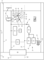
- FIG. 1 An example of a railway vehicle 10 is illustrated in the figure 1 .
- the vehicle 10 comprises at least one car 12, for example a plurality of cars 12.
- the figure 1 illustrates for example at least two cars 12.
- the vehicle 10 includes a traction system, not illustrated, capable of generating the mechanical energy necessary to ensure the movement of the vehicle 10.
- the vehicle 10 comprises an electrical power system 14, a main compressed air line 16, a compressed air production unit 18, a general compressed air braking line 20, a general pressure control system 22 , and at least one braking control system 24 of the vehicle 10.
- the vehicle 10 comprises a plurality of braking control systems 24, each car 12 comprising at least one of the braking control systems 24.
- the vehicle 10 also includes a pneumatic control system 26 of the main pressure of the main pipe 16.
- the vehicle 10 also includes, for example, a control and management system TCMS (in English “Train Control and management System”), not illustrated, capable of actively monitoring the state of the braking functions of the vehicle 10.
- TCMS in English “Train Control and management System”
- Each car 12 includes at least one bogie not illustrated.
- Each bogie carries at least one axle, each axle includes two wheels and a transverse axle.
- the traction system of the railway vehicle 10 is capable of rotating each axle to move the vehicle 10 forward.
- At least one of the cars 12 comprises at least one pneumatic consumer 28 not dedicated to braking and connected to the main pipe 16.
- Each pneumatic consumer 28 not dedicated to braking is capable of presenting an operating configuration, during which the pneumatic consumer 28 consumes compressed air to implement a non-braking function.
- the electrical power system 14 is capable of providing electrical power.
- the electrical power system 14 is known to those skilled in the art and will not be described in more detail below.
- the electrical power supplied is used in particular by the various consumers 28 of the vehicle 10.
- the air production unit 18 is for example located in the or one of the cars 12 of the railway vehicle 10.
- the air production unit 18 is capable of generating compressed air from a power supply supplied by the power supply system 14.
- the production unit 18 is capable of supplying compressed air to the main pipe 16.
- the air production unit 18 comprises at least one compressor not illustrated.
- the or each compressor is capable of taking air from outside the vehicle 10 and transmitting it to the main pipe 16, in a known manner.
- the main compressed air line 16 presents a main pressure.
- the nominal main pressure is for example between 7 bar and 10 bar.
- the main pressure is provided by the air production unit 18.
- the main pipe 16 is intended to supply each pneumatic consumer 28 not dedicated to braking, as well as certain elements of the braking control system 24 as described below.
- the main pipe 16 extends for example over the length of the railway vehicle 10. In particular, it is understood that the main pipe 16 extends over all the cars 12 of the vehicle 10.
- the general braking line 20 comprises for example one section per car 12 of the vehicle 10.
- Two sections of two adjacent cars 12 are for example connected pneumatically by hoses.
- the hoses can be decoupled to allow separation of cars 12.
- the general pressure control system 22 is capable of supplying compressed air to the general braking line 20, in particular from the compressed air of the main line 16.
- the general pressure control system 22 is capable of regulating the supply of compressed air to the general braking line 20, for example via a control member not illustrated.
- the general braking line 20 is distinct from the main line 16.
- the general braking line 20 is capable of transmitting a braking instruction from the driver to the entire railway vehicle 10.
- the general braking pipe 20 extends over the length of the railway vehicle 10.
- the general braking line 20 extends over all the cars 12 of the vehicle 10.
- the general line 20 thus runs through the vehicle 10 from end to end.
- the general braking line 20 comprises for example one section per car 12 of the vehicle 10.
- Two sections of two adjacent cars 12 are for example connected pneumatically by hoses.
- the hoses can be decoupled to allow separation of cars 12.
- the general braking pipe 20 has a so-called general pressure and is supplied, via said control member not illustrated, by the general pressure control system 22.
- the control unit can be operated by the driver.
- the control body is for example a mechanic's valve.
- Other control bodies are known to those skilled in the art and will not be described here.
- the control member is capable of varying the general pressure in the general pipe 20 from 0 bar to a predetermined maximum general pressure.
- the predetermined maximum general pressure is for example greater than or equal to 4 bar, for example equal to 5 bar.
- the general braking line 20 is capable of transmitting pressure variations necessary to control braking.
- the driver of the railway vehicle 10 adjusts his braking by adjusting the general pressure, via the control member.
- Each braking control system 24 of the railway vehicle 10 is capable of automatically triggering braking as a function of the general pressure of the general pipe 20.
- each braking control system 24 comprises, in known manner, a compressed air braking reservoir 30, at least one pneumatic brake 32 and a distribution system 34.
- the brake reservoir 30 is supplied with compressed air via the main pipe 16, preferably via a non-return valve 36.
- Each pneumatic brake 32 is capable of being supplied by a braking pressure supplied by the braking reservoir 30, and is capable of exerting a braking force on the vehicle 10 as a function of the braking pressure supplied.
- the braking force exerted depends on said supplied braking pressure.
- Each pneumatic brake 32 includes a brake cylinder 38.
- Each brake cylinder 38 comprises, for example, a piston connected to a brake pad.
- the brake pad is able to come into contact with an element of one of the wheels of the car 12 to brake the vehicle 10.
- the piston moves according to the change in air pressure in the brake cylinder 38, that is to say according to said supplied brake pressure.
- the distribution system 34 is capable of automatically authorizing the supply of pressure to the or each pneumatic brake 32 from the braking reservoir 30, as a function of the general pressure of the general pipe 20.
- the distribution system 34 comprises at least one distribution valve 40 and a relay valve 42.
- the distribution valve 40 is then capable of controlling the relay valve 42 to automatically authorize the supply of pressure to the or each pneumatic brake 32 from the braking reservoir 30, as a function of the general pressure of the general pipe 20.
- Said supply is for example authorized automatically when the general pressure of the general braking line 20 falls below a general pressure threshold.
- the braking control system 24 is thus capable of controlling braking according to an inverted braking control law: an increase in general pressure reduces braking and a decrease increases braking.
- the general braking line 20 is supplied at a pressure of 5 bars.
- the brakes are applied and exert the braking force.
- a reduction in general pressure in the general braking line 20 is for example caused by a braking command from the driver, an emergency command by one of the passengers of the vehicle 10 by means of an emergency system intended for the passengers, or even a rupture of the general pipe 20.
- braking is automatic to the extent that it is the absence of energy in its control (whether electric or pneumatic) which produces the most conservative result, namely the application of braking.
- Braking is preferably also continuous.
- the general braking line 20 controls in this preferred example all the brake assemblies (distributor, brake cylinder) present on each car 12 of the vehicle 10.
- the vehicle 10 comprises said pneumatic control system 26 of the main pressure of the main pipe 16 which will now be describe.
- the pneumatic control system 26 is capable of automatically comparing the main pressure of the main line 16 with at least the general pressure of the main line 20.
- this is the comparison of the main pressure of the main pipe 16 with at least the sum of the general pressure of the general pipe 20 and the elastic return 49 described in more detail below.
- the pneumatic control system 26 is capable of automatically evacuating the compressed air from the general pipe 20 out of the general pipe 20, when the main pressure of the main pipe 16 falls below a main emergency pressure threshold .
- the pneumatic control system 26 is removable relative to the general pipe 20 and the main pipe 16. It is thus capable of being connected to said pipes 16, 20 only when necessary.
- vehicle 10 requires only one pneumatic control system 26 as described.
- the pneumatic control system 26 of the main pressure preferably comprises at least one comparator distributor 44.
- the pneumatic control system 26 also includes, for example, a flow reducer 46 and an evacuation distributor 48.
- the comparator distributor 44 is a pneumatically operated pneumatic distributor with elastic return 49.
- the elastic return 49 is applied by a spring.
- the spring is preferably adjustable.
- the elastic return 49 enters into the control of the position of the comparator distributor 44.
- the comparator distributor 44 has at least one pneumatic supply inlet connected to the general pipe 20 and at least one pneumatic exhaust outlet connected to the outside air.
- the comparator distributor 44 also has a first control input connected to the main pipe 16 and a second control input connected to the general pipe 20.
- the pneumatic control system 26 comprises a main branch 50 having an inlet directly connected to the main pipe 16 and an outlet directly connected to the first control input of the comparator distributor 44.
- the pneumatic control system 26 comprises a first general branch 52 having an inlet pneumatically connected to the general pipe 20 and an output directly connected to the second control input of the comparator distributor 44.
- the pneumatic control system 26 comprises a second general branch 54 having an inlet pneumatically connected to the general pipe 20 and an outlet directly connected to the pneumatic supply inlet of the comparator distributor 44.
- the comparator distributor 44 has at least one open position, in which the pneumatic supply inlet is placed in fluid communication with the pneumatic exhaust outlet, and a closed position, in which the pneumatic supply inlet does not communicate with pneumatic exhaust outlet.
- the comparator distributor 44 is illustrated in the open position.
- the comparator distributor 44 is for example a 2/2 distributor.
- the elastic return 49 of the comparator distributor 44 is determined so that, when the main pressure of the main pipe 16 falls below a main emergency pressure threshold, the comparator distributor 44 goes into the open position.
- the main emergency pressure threshold is greater than or equal to the minimum pressure to implement braking by all of the pneumatic brakes 32 of the vehicle 10.
- the flow reducer 46 is here interposed between the second control input of the comparator distributor 44 and the general braking pipe 20.
- the flow reducer 46 is arranged on said second general branch 54 (i.e. the branch having its outlet connected to the pneumatic supply inlet of the comparator distributor 44).
- the flow reducer 46 is for example non-adjustable.
- the flow reducer 46 is configured to decouple the pressure levels between the branch 54 and the branch 56 when opening the comparator distributor 44.
- the exhaust through the outlet of the comparator distributor 44 has a predetermined flow rate sufficient to cancel the compensation of the filling flow rate of the branch 54 passing through the flow reducer 46.
- the evacuation distributor 48 is a pneumatically operated pneumatic distributor with elastic return.
- the evacuation distributor 48 has at least one pneumatic supply inlet connected to the general pipe 20 and at least one pneumatic exhaust outlet connected to the outside air.
- the evacuation distributor 48 also has a first control input connected to the general pipe 20 and a second control input connected to a tapping point 55 on said second general branch 54.
- the tapping point 55 is for example interposed between the flow reducer 46 and the pneumatic supply inlet of the comparator distributor 44.
- the pneumatic control system 26 comprises a third general branch 56 having an inlet pneumatically connected to the general pipe 20 and an outlet directly connected to the first control input of the evacuation distributor 48.
- the pneumatic control system 26 comprises a fourth general branch 58 having an inlet pneumatically connected to the general pipe 20 and an outlet directly connected to the pneumatic supply inlet of the evacuation distributor 48.
- the evacuation distributor 48 has at least one open position, in which the pneumatic supply inlet is placed in fluid communication with the pneumatic exhaust outlet of the evacuation distributor 48, and a closed position, in which the Pneumatic supply inlet does not communicate with the pneumatic exhaust outlet.
- the discharge distributor 48 is illustrated in the closed position.
- the evacuation distributor 48 is for example a 2/2 distributor.
- the third and fourth general branches connect to a tapping point upstream of the flow reducer 46.
- the flow in the third and fourth general branches is not influenced by the flow reducer 46.
- the exhaust has a predetermined flow rate greater than the predetermined flow rate of the comparator distributor 44 open.
- Said predetermined flow rate of the evacuation distributor 48 is for example greater than the leakage compensation flow rate of the general pipe 20 of the general pressure control system 22.
- the spring return of the evacuation distributor 48 is determined so that, when the pressures of the first and second control inputs are equal, the evacuation distributor 48 is in the closed position.
- the elastic return of the evacuation distributor 48 is determined so that, when the pressure of the first control inlet of the distributor 48 is greater than the pressure of the second control inlet of the distributor 48, the evacuation distributor 48 is in position opened.
- the comparator distributor 44 switches to the open position. Via the flow reducer 46, an imbalance is created between the pressures of the first and second control inputs of the evacuation distributor 48 which causes the evacuation distributor 48 to move into the open position.
- the general pipe 20 is then placed in fluid communication with the outside air and is emptied.
- the pneumatic control system 26 of the main pressure comprises an isolation valve 60.
- the isolation valve 60 is interposed between the second control input of the comparator distributor 44 and the general braking line 20.
- the isolation valve 60 can be manually actuated between an air passage authorization configuration and an air passage prohibition configuration.
- the isolation valve 60 makes it possible not to use the control system 26, for example in the case where it is not necessary to use it in a nominal situation.
- control system does not have such an isolation valve 60.
- a method of towing a railway vehicle 10 towed by another towing railway vehicle 62 will now be described, the towed vehicle 10 corresponding to the vehicle 10 described above.
- the method is for example implemented for a rescue operation of the towed vehicle 10.
- the towed vehicle 10 is for example in a faulty state.
- At least the compressed air production unit 18 of the towed vehicle 10 is incapable of supplying compressed air to the main pipe 16 of the towed vehicle 10.
- the electrical power system 14 of the vehicle towed 10 has broken down, and is unable to provide electrical power to the compressed air production unit 18.
- the TCMS control and management system is faulty.
- the traction system of the towed vehicle 10 is for example incapable of ensuring the movement of the vehicle 10.
- the traction system of the towed vehicle 10 is incapable of rotating the axles to move the vehicle 10 forward.
- the towed vehicle 10 requires the towing vehicle 62 to move. In other words, the entire towed vehicle 10 and the towing vehicle 62 is moved solely by the traction system of the towing vehicle 62.
- the towing vehicle 62 comprises at least one electrical power system, a main compressed air pipe 64, a compressed air production unit, a general compressed air braking pipe 66, a general pressure control system and a system for controlling the braking of the towing vehicle 62.
- the method includes a step of connecting the respective main pipes 16, 64 of the towed railway vehicles 10 and tug 62, and a step of connecting the respective general braking pipes 20, 66 of the towed railway vehicles 10 and tug 62.
- connections are for example implemented by means of a known dedicated interface 68.
- the main pipe 16 of the towed vehicle 10 is then supplied with main pressure by the main pipe 64 of the towing vehicle 62.
- the general braking line 20 of the towed vehicle 10 is thus supplied with general pressure by the general line 66 of the towing vehicle 62.
- the method comprises a step of connecting the pneumatic control system 26 to the general pipe 20 and to the main pipe 16 of the towed vehicle 10, the system 26 being previously away from said pipes 16, 20.
- the method includes a step of towing the towed vehicle 10 by the towing vehicle 62.
- the towing step includes moving the entire towed vehicle 10 and the towing vehicle 62 by the traction system of the towing vehicle 62.
- the towed vehicle 10 is pushed by the towing vehicle 62.
- the towing step also includes controlling the main pressure of the main pipe 16 of the towed vehicle 10 by the pneumatic control system 26.
- This control is implemented at least during said movement of the entire towed vehicle 10 and the towing vehicle 62.
- the pneumatic control system 26 automatically compares the main pressure of the main line 16 with at least the general pressure of the main line 20.
- this is the comparison of the main pressure of the main pipe 16 with at least the sum of the general pressure of the general pipe 20 and the elastic return 49.
- the pneumatic control system 26 automatically discharges the compressed air of the main line 20 out of the main line 20.
- the braking of the towed vehicle 10 is thus caused automatically by the braking control system 24 of the towed vehicle 10.
- the towing vehicle 62 is also braked by the reaction of its braking control system which reacts to the change in pressure of the general pipe 66 connected and continues to the general pipe 20 of the towed vehicle 10.
- an automatic emergency braking action via the general braking pipe 20 is implemented when the pressure of the main pipe 16 becomes too low, that is to say below which we loses the ability to apply at least one emergency braking by the towed vehicle 10.
- the invention remains simple in that it is not necessary to develop it on each braking reservoir 30, as in the case of the first solution.
- the invention also gives more freedom in its use, to the extent that the pneumatic control system 26 can be considered as a mobile and removable device, to be installed only during an emergency operation.
- the invention also complies with standards EN 14198 and EN 16185-1, imposing as a constraint that the compressed air from the reservoirs of the braking system and the general braking pipe 20 is not used for any purpose other than braking. In fact, these standards do not require that the compressed air from the general braking line 20 and from each braking reservoir 30 be used exclusively to provide power to the braking actuators.
- the solution of the invention uses the air from the main braking line 20 to trigger emergency braking under a pressure threshold in the main line 16. The purpose of the compressed air used in this solution is therefore exclusively linked to braking.
Landscapes
- Engineering & Computer Science (AREA)
- Transportation (AREA)
- Mechanical Engineering (AREA)
- Valves And Accessory Devices For Braking Systems (AREA)
- Braking Systems And Boosters (AREA)
Description
La présente invention concerne un véhicule ferroviaire du type comprenant :
- un système d'alimentation électrique ;
- une conduite principale d'air comprimé présentant une pression principale ;
- une unité de production d'air comprimé, propre à générer de l'air comprimé à partir d'une alimentation électrique fournie par le système d'alimentation électrique, l'unité de production étant propre à alimenter en air comprimé la conduite principale ;
- une conduite générale de freinage d'air comprimé présentant une pression générale ;
- un système de contrôle de pression générale propre à alimenter en air comprimé la conduite générale à partir de l'air comprimé de la conduite principale ;
- au moins un système de commande du freinage du véhicule ferroviaire propre à déclencher automatiquement le freinage en fonction de la pression générale de la conduite générale, le système de commande du freinage comprenant :
- * un réservoir de freinage d'air comprimé, le réservoir de freinage étant alimenté en air comprimé par la conduite principale,
- * un frein pneumatique, le frein pneumatique étant propre à être alimenté par une pression de freinage fournie par le réservoir de freinage, et propre à exercer une force de freinage du véhicule en fonction de la pression de freinage alimentée ;
- * un système de distribution propre à autoriser automatiquement l'alimentation en pression du ou de chaque frein pneumatique depuis le réservoir de freinage, en fonction de la pression générale de la conduite générale.
- a power supply system;
- a main compressed air pipe having a main pressure;
- a compressed air production unit, capable of generating compressed air from an electrical supply supplied by the electrical power system, the production unit being capable of supplying compressed air to the main pipe;
- a general compressed air braking pipe having a general pressure;
- a general pressure control system capable of supplying compressed air to the general pipe from the compressed air of the main pipe;
- at least one braking control system of the railway vehicle capable of automatically triggering braking as a function of the general pressure of the general pipe, the braking control system comprising:
- * a compressed air braking tank, the braking tank being supplied with compressed air via the main pipe,
- * a pneumatic brake, the pneumatic brake being capable of being supplied by a braking pressure supplied by the braking reservoir, and capable of exerting a braking force on the vehicle as a function of the braking pressure supplied;
- * a distribution system capable of automatically authorizing the supply of pressure to the or each pneumatic brake from the brake reservoir, depending on the general pressure of the general pipe.
En cas de problème, notamment d'alimentation électrique, un tel véhicule peut se retrouver dans un état de défaillance. Le véhicule est alors secouru par un autre véhicule, dit de secours, qui est aussi du type précité.In the event of a problem, particularly with the power supply, such a vehicle may find itself in a state of failure. The vehicle is then rescued by another vehicle, called an emergency vehicle, which is also of the aforementioned type.
L'état de défaillance du véhicule secouru implique par exemple que :
- le système de contrôle et de gestion TCMS (en anglais « Train Control and management System ») du véhicule secouru est défaillant, et aucune surveillance active de l'état des fonctions de freinage du véhicule secouru n'est mise en oeuvre ; et/ou
- aucune alimentation de moyenne tension n'est disponible à bord du véhicule secouru, le système d'alimentation électrique du véhicule secouru étant par exemple en panne, de sorte que l'unité de production d'air comprimé n'est plus en mesure d'alimenter en pression la conduite principale du véhicule secouru.
- the TCMS control and management system (in English “Train Control and management System”) of the rescued vehicle is faulty, and no active monitoring of the state of the braking functions of the rescued vehicle is implemented; and or
- no medium voltage power supply is available on board the rescued vehicle, the electrical power system of the rescued vehicle being for example in breakdown, so that the compressed air production unit is no longer able to supply pressure to the main pipe of the rescued vehicle.
Lors de cette opération de secours, les conduites principales MRP des deux véhicules sont connectées l'une à l'autre et les conduites générales de freinage BP des deux véhicules sont aussi connectées l'une à l'autre, ces connexions étant mises en oeuvre par un dispositif d'interface dédié. Cette connexion permet en temps normal le maintien en pression de la conduite principale MRP et de la conduite générale de freinage BP du véhicule secouru grâce, respectivement, à celles du véhicule de secours.During this emergency operation, the main MRP pipes of the two vehicles are connected to each other and the general BP braking pipes of the two vehicles are also connected to each other, these connections being implemented by a dedicated interface device. This connection normally allows the maintenance of pressure in the main MRP pipe and the general BP braking pipe of the rescued vehicle thanks, respectively, to those of the rescue vehicle.
Cependant, des problèmes d'alimentation en pression de la conduite principale MRP ou de la conduite générale BP du véhicule secouru, par le véhicule de secours, peuvent survenir, malgré cette connexion par le dispositif d'interface dédié.However, problems with the pressure supply of the main MRP pipe or the main BP pipe of the rescued vehicle, by the rescue vehicle, may occur, despite this connection by the dedicated interface device.
En particulier, une interruption (sans fuite d'air) de la continuité entre la conduite principale MRP du véhicule de secours et celle du véhicule secouru (par exemple par fermeture d'un robinet, ou obstruction de la conduite) pourrait rester non détectée par le conducteur du véhicule de secours. Dans un tel cas, la pression dans la conduite principale MRP, et donc dans chaque réservoir de freinage BR, du véhicule secouru pourrait se vider, suite à des freinages successifs, jusqu'à ce qu'il ne reste pas assez d'air pour réaliser un freinage par le véhicule secouru.In particular, an interruption (without air leak) of the continuity between the main MRP pipe of the emergency vehicle and that of the rescued vehicle (for example by closing a valve, or obstruction of the pipe) could remain undetected by the driver of the emergency vehicle. In such a case, the pressure in the main MRP pipe, and therefore in each braking reservoir BR, of the rescued vehicle could be emptied, following successive braking operations, until there is not enough air remaining to braking by the rescued vehicle.
Une telle situation présente un risque élevé d'accident pour l'ensemble du véhicule secouru et du véhicule de secours.Such a situation presents a high risk of accident for the entire rescued vehicle and the rescue vehicle.
Il est donc nécessaire de s'assurer que le véhicule secouru soit en capacité de freiner, par exemple suite à une commande par le véhicule de secours, ou que le conducteur du véhicule secouru soit informé, et/ou qu'une action se produise (exemple : commander un freinage d'urgence) si cette capacité de freiner n'est plus assurée.It is therefore necessary to ensure that the rescued vehicle is able to brake, for example following a command by the rescue vehicle, or that the driver of the rescued vehicle is informed, and/or that an action occurs ( example: order emergency braking) if this ability to brake is no longer guaranteed.
Pour ce faire, il est déjà connu de fournir une première solution permettant le remplissage de chaque réservoir de freinage d'air du véhicule secouru à partir de l'air comprimé de la conduite générale de freinage du véhicule secouru. Chaque réservoir de freinage du véhicule secouru est alors alimenté à la fois par la conduite principale MRP et par la conduite générale de freinage BP du véhicule secouru.To do this, it is already known to provide a first solution allowing the filling of each air braking reservoir of the rescued vehicle from the compressed air of the general braking pipe of the rescued vehicle. Each braking reservoir of the rescued vehicle is then supplied both by the main MRP pipe and by the general BP braking pipe of the rescued vehicle.
Cependant, cette première solution n'est pas satisfaisante.However, this first solution is not satisfactory.
En effet, cette première solution nécessite d'être installée au niveau de chaque réservoir de freinage. En outre, cette solution pourrait ne pas être disponible sur certains véhicules ferroviaires déjà en exploitation.In fact, this first solution requires being installed at each brake reservoir. In addition, this solution may not be available on certain rail vehicles already in operation.
Il est aussi connu une deuxième solution dans laquelle la conduite principale du véhicule secouru est connectée pneumatiquement à la conduite générale de freinage du véhicule secouru par l'intermédiaire d'une conduite, d'un robinet d'isolement et d'un clapet anti-retour autorisant l'alimentation en pression de la conduite principale par la conduite générale de freinage.A second solution is also known in which the main pipe of the rescued vehicle is pneumatically connected to the general braking pipe of the rescued vehicle via a pipe, an isolation valve and a valve anti-return device allowing pressure to be supplied to the main pipe via the general braking pipe.
Cependant, cette deuxième solution n'est pas satisfaisante.However, this second solution is not satisfactory.
En effet, cette deuxième solution n'est pas conforme aux normes EN 14198 et EN 16185-1, imposant pour contrainte que l'air comprimé des réservoirs du système de freinage et de la conduite générale de freinage ne soit utilisé pour aucun autre but que le freinage. L'air comprimé de la conduite générale de freinage alimente alors la conduite principale et peut être utilisée à d'autres fins que le freinage.In fact, this second solution does not comply with standards EN 14198 and EN 16185-1, requiring that the compressed air from the braking system reservoirs and the general braking pipe be used for no other purpose than braking. The compressed air from the main brake line then supplies the main line and can be used for purposes other than braking.
Un but de l'invention est de fournir une solution simple permettant d'éviter que le véhicule secouru se retrouve dans une situation d'incapacité à freiner.An aim of the invention is to provide a simple solution making it possible to prevent the rescued vehicle from finding itself in a situation of being unable to brake.
De plus, en complément, il serait aussi souhaitable que la solution soit conforme aux normes EN 14198 et EN 16185-1.Furthermore, in addition, it would also be desirable for the solution to comply with standards EN 14198 and EN 16185-1.
A cet effet, l'invention concerne un véhicule du type précité, caractérisé en ce que le véhicule ferroviaire comprend en outre un système de contrôle pneumatique de la pression principale de la conduite principale, le système de contrôle pneumatique étant propre à comparer automatiquement la pression principale de la conduite principale avec au moins la pression générale de la conduite générale, et étant propre à évacuer automatiquement l'air comprimé de la conduite générale hors de la conduite générale, lorsque la pression principale de la conduite principale passe en-dessous d'un seuil principal de pression d'urgence.For this purpose, the invention relates to a vehicle of the aforementioned type, characterized in that the railway vehicle further comprises a system for pneumatic control of the main pressure of the main pipe, the pneumatic control system being capable of automatically comparing the pressure main pipe of the main pipe with at least the general pressure of the general pipe, and being capable of automatically evacuating the compressed air of the general pipe out of the general pipe, when the main pressure of the main pipe falls below a main emergency pressure threshold.
Ainsi, le problème d'éviter que le véhicule remorqué se retrouve dans une situation d'incapacité à freiner est résolu non pas en assurant que les réservoirs de freinage sont toujours remplis, comme dans le cas des première et deuxième solutions, mais en contrôlant la pression principale de la conduite principale, dans la mesure où ce sera la pression la plus faible qui puisse être présent dans chaque réservoir de freinage.Thus, the problem of preventing the towed vehicle from finding itself in a situation of being unable to brake is solved not by ensuring that the braking reservoirs are always filled, as in the case of the first and second solutions, but by controlling the main pressure of the main line, as this will be the lowest pressure that can be present in each brake reservoir.
Le véhicule selon l'invention peut comprendre l'une ou plusieurs des caractéristiques suivantes, prise(s) isolément ou suivant toute combinaison techniquement possible :
- le véhicule comprend une pluralité de systèmes de commande du freinage et le seuil principal de pression d'urgence est supérieur ou égal à la pression minimale pour mettre en oeuvre un freinage par l'ensemble des freins pneumatiques du véhicule ;
- lequel le système de contrôle pneumatique de la pression principale comprend au moins un distributeur comparateur, le distributeur comparateur étant un distributeur pneumatique à commande pneumatique avec rappel élastique, le distributeur comparateur présentant au moins une entrée d'alimentation pneumatique connectée à la conduite générale et au moins une sortie d'échappement pneumatique raccordée à l'air extérieur, le distributeur comparateur présentant une première entrée de commande connectée à la conduite principale et une deuxième entrée de commande connectée à la conduite générale ;
- le système de contrôle pneumatique est propre à comparer automatiquement la pression principale de la conduite principale avec au moins la somme de la pression générale de la conduite générale et du rappel élastique ;
- le système de contrôle pneumatique de la pression principale comprend une branche générale ayant une entrée connectée pneumatiquement à la conduite générale et une sortie directement raccordée à l'entrée d'alimentation pneumatique du distributeur comparateur, le système de contrôle pneumatique de la pression principale comprenant aussi un réducteur de débit disposé sur ladite branche générale et interposé entre la deuxième entrée de commande du distributeur comparateur et la conduite générale de freinage, le réducteur de débit étant par exemple non réglable ;
- le système de contrôle pneumatique de la pression principale comprend au moins un distributeur d'évacuation, le distributeur d'évacuation étant un distributeur pneumatique à commande pneumatique avec rappel élastique, le distributeur d'évacuation présentant au moins une entrée d'alimentation pneumatique connectée à la conduite générale et au moins une sortie d'échappement pneumatique raccordée à l'air extérieur, le distributeur d'évacuation présentant une première entrée de commande connectée à la conduite générale et une deuxième entrée de commande connectée à un point de piquage sur ladite branche générale ;
- le système de contrôle pneumatique de la pression principale comprend un robinet d'isolement interposé entre la deuxième entrée de commande du distributeur comparateur et la conduite générale de freinage, le robinet d'isolement étant actionnable manuellement entre une configuration d'autorisation de passage d'air et une configuration d'interdiction de passage d'air ;
- le système de distribution comprend une valve de distribution et une valve-relai, la valve de distribution étant propre à commander la valve-relai pour autoriser automatiquement l'alimentation en pression du ou de chaque frein pneumatique depuis le réservoir de freinage, en fonction de la pression générale de la conduite générale ;
- le système de distribution est propre à autoriser automatiquement l'alimentation en pression du ou de chaque frein pneumatique depuis le réservoir de freinage lorsque la pression générale de la conduite générale de freinage passe en dessous d'un seuil général de pression ;
- le système de contrôle pneumatique est amovible par rapport à la conduite générale et à la conduite principale ; et
- le véhicule comprend aussi au moins un consommateur pneumatique non-dédié au freinage et connecté à la conduite principale, le consommateur pneumatique étant propre à présenter une configuration de fonctionnement, au cours de laquelle le consommateur pneumatique consomme de l'air comprimé pour mettre en oeuvre une fonction hors-freinage.
- the vehicle comprises a plurality of braking control systems and the main emergency pressure threshold is greater than or equal to the minimum pressure to implement braking by all of the vehicle's air brakes;
- which the pneumatic main pressure control system comprises at least one comparator distributor, the comparator distributor being a pneumatically controlled pneumatic distributor with elastic return, the comparator distributor having at least one pneumatic supply inlet connected to the general pipe and to the minus a pneumatic exhaust outlet connected to the outside air, the comparator distributor having a first control input connected to the main pipe and a second control input connected to the main pipe;
- the pneumatic control system is capable of automatically comparing the main pressure of the main pipe with at least the sum of the general pressure of the general pipe and the elastic return;
- the pneumatic main pressure control system comprises a general branch having an inlet pneumatically connected to the general pipe and an outlet directly connected to the pneumatic supply inlet of the comparator distributor, the pneumatic main pressure control system also comprising a flow reducer arranged on said general branch and interposed between the second control input of the comparator distributor and the general braking line, the flow reducer being for example non-adjustable;
- the main pressure pneumatic control system comprises at least one exhaust distributor, the exhaust distributor being a pneumatically operated pneumatic distributor with spring return, the exhaust distributor having at least one pneumatic supply inlet connected to the general pipe and at least one pneumatic exhaust outlet connected to the outside air, the evacuation distributor having a first control input connected to the general pipe and a second control input connected to a tapping point on said branch general;
- the pneumatic control system of the main pressure comprises an isolation valve interposed between the second control input of the comparator distributor and the general braking pipe, the isolation valve being manually actuable between a configuration of authorization of passage of air and an air passage prevention configuration;
- the distribution system comprises a distribution valve and a relay valve, the distribution valve being capable of controlling the relay valve to automatically authorize the supply of pressure to the or each air brake from the brake reservoir, depending on the general pressure of the main pipe;
- the distribution system is capable of automatically authorizing the supply of pressure to the or each pneumatic brake from the braking reservoir when the general pressure of the general braking line falls below a general pressure threshold;
- the pneumatic control system is removable from the general pipe and the main pipe; And
- the vehicle also comprises at least one pneumatic consumer not dedicated to braking and connected to the main pipe, the pneumatic consumer being able to present an operating configuration, during which the pneumatic consumer consumes compressed air to implement a non-braking function.
De plus, l'invention concerne aussi une méthode de remorquage d'un véhicule ferroviaire remorqué par un autre véhicule ferroviaire remorqueur,
- le véhicule ferroviaire remorqué étant tel que décrit ci-dessus, le véhicule remorqué étant dans un état de défaillance, dans lequel au moins l'unité de production d'air comprimé est incapable d'alimenter en air comprimé la conduite principale du véhicule remorqué,
- le véhicule remorqueur comprenant au moins une conduite principale et une conduite générale de freinage,
- la méthode comprenant les étapes suivantes :
- connexion des conduites principales respectives des véhicules ferroviaires remorqué et remorqueur ;
- connexion des conduites générales de freinage respectives des véhicules ferroviaires remorqué et remorqueur ;
- remorquage du véhicule remorqué par le véhicule remorqueur, l'étape de remorquage comprenant au moins le contrôle de la pression principale de la conduite principale du véhicule remorqué par ledit système de contrôle pneumatique.
- the towed railway vehicle being as described above, the towed vehicle being in a faulty state, in which at least the compressed air production unit is incapable of supplying compressed air to the main pipe of the towed vehicle,
- the towing vehicle comprising at least one main pipe and a general braking pipe,
- the method comprising the following steps:
- connection of the respective main pipes of the towed and towed railway vehicles;
- connection of the respective general braking lines of the towed and towed railway vehicles;
- towing of the vehicle towed by the towing vehicle, the towing step comprising at least controlling the main pressure of the main pipe of the towed vehicle by said pneumatic control system.
L'invention sera mieux comprise à la lecture de la description qui va suivre, donnée uniquement à titre d'exemple, et faite en se référant au dessin annexé, sur lequel :
- la
figure 1 est un organigramme schématique d'un véhicule selon un exemple de réalisation de l'invention.
- there
figure 1 is a schematic flowchart of a vehicle according to an exemplary embodiment of the invention.
Un exemple de véhicule ferroviaire 10 est illustré sur la
Le véhicule 10 comprend au moins une voiture 12, par exemple une pluralité de voitures 12. La
Le véhicule 10 comprend un système de traction non illustré propre à générer l'énergie mécanique nécessaire pour assurer le déplacement du véhicule 10.The
Le véhicule 10 comprend un système d'alimentation électrique 14, une conduite principale 16 d'air comprimé, une unité de production d'air comprimé 18, une conduite générale 20 de freinage d'air comprimé, un système de contrôle de pression générale 22, et au moins un système de commande du freinage 24 du véhicule 10.The
Le véhicule 10 comprend une pluralité de systèmes de commande du freinage 24, chaque voiture 12 comprenant au moins un des systèmes de commande du freinage 24.The
Le véhicule 10 comprend aussi un système de contrôle pneumatique 26 de la pression principale de la conduite principale 16.The
Le véhicule 10 comprend aussi par exemple un système de contrôle et de gestion TCMS (en anglais « Train Control and management System ») non illustré propre à surveiller activement l'état des fonctions de freinage du véhicule 10.The
Chaque voiture 12 comprend au moins un bogie non illustré.Each
Chaque bogie porte au moins un essieu, chaque essieu comprend deux roues et un axe transversal.Each bogie carries at least one axle, each axle includes two wheels and a transverse axle.
Le système de traction du véhicule ferroviaire 10 est propre à mettre en rotation chaque essieu pour faire avancer le véhicule 10.The traction system of the
Au moins une des voitures 12 comprend au moins un consommateur pneumatique 28 non-dédié au freinage et connecté à la conduite principale 16.At least one of the
Chaque consommateur pneumatique 28 non-dédié au freinage est propre à présenter une configuration de fonctionnement, au cours de laquelle le consommateur pneumatique 28 consomme de l'air comprimé pour mettre en oeuvre une fonction hors-freinage.Each
Le système d'alimentation électrique 14 est propre à fournir une alimentation électrique.The
Le système d'alimentation électrique 14 est connu de l'homme du métier et ne sera pas décrit plus en détails par la suite.The
L'alimentation électrique fournie est notamment utilisée par les différents consommateurs 28 du véhicule 10.The electrical power supplied is used in particular by the
L'unité de production d'air 18 est par exemple située dans la ou une des voitures 12 du véhicule ferroviaire 10.The
L'unité de production d'air 18 est propre à générer de l'air comprimé à partir d'une alimentation électrique fournie par le système d'alimentation électrique 14.The
L'unité de production 18 est propre à alimenter en air comprimé la conduite principale 16.The
Pour cela, l'unité de production d'air 18 comprend au moins un compresseur non illustré.For this, the
Le ou chaque compresseur est propre à prendre de l'air à l'extérieur au véhicule 10 et à le transmettre à la conduite principale 16, de manière connue.The or each compressor is capable of taking air from outside the
La conduite principale 16 d'air comprimé présente une pression principale.The main
Dans une situation nominale du véhicule ferroviaire 10, la pression principale nominale est par exemple comprise entre 7 bar et 10 bar.In a nominal situation of the
Comme indiqué ci-dessus, la pression principale est fournie par l'unité de production d'air 18.As indicated above, the main pressure is provided by the
La conduite principale 16 est destinée à alimenter chaque consommateur pneumatique 28 non-dédié au freinage, ainsi que certains éléments du système de commande du freinage 24 comme décrit par la suite.The
La conduite principale 16 s'étend par exemple sur la longueur du véhicule ferroviaire 10. On entend en particulier que la conduite principale 16 s'étend sur toutes les voitures 12 du véhicule 10.The
La conduite générale de freinage 20 comprend par exemple une section par voiture 12 du véhicule 10.The
Deux sections de deux voitures 12 adjacentes sont par exemple reliées de manière pneumatique par des flexibles. Les flexibles peuvent être découplés pour permettre la séparation des voitures 12.Two sections of two
Le système de contrôle de pression générale 22 est propre à alimenter en air comprimé la conduite générale de freinage 20, en particulier à partir de l'air comprimé de la conduite principale 16.The general pressure control system 22 is capable of supplying compressed air to the
Le système de contrôle de pression générale 22 est propre à réguler l'alimentation en air comprimé de la conduite générale de freinage 20, par exemple par l'intermédiaire d'un organe de contrôle non illustré.The general pressure control system 22 is capable of regulating the supply of compressed air to the
La conduite générale de freinage 20 est distincte de la conduite principale 16.The
La conduite générale de freinage 20 est propre à transmettre une consigne de freinage du conducteur sur l'ensemble du véhicule ferroviaire 10.The
Pour cela, la conduite générale de freinage 20 s'étend sur la longueur du véhicule ferroviaire 10.For this, the
On entend en particulier que la conduite générale de freinage 20 s'étend sur toutes les voitures 12 du véhicule 10. La conduite générale 20 parcourt ainsi le véhicule 10 de bout en bout.In particular, it is understood that the
La conduite générale de freinage 20 comprend par exemple une section par voiture 12 du véhicule 10.The
Deux sections de deux voitures 12 adjacentes sont par exemple reliées de manière pneumatique par des flexibles. Les flexibles peuvent être découplés pour permettre la séparation des voitures 12.Two sections of two
De plus, la conduite générale de de freinage 20 présente une pression dite générale et est alimentée, via ledit organe de contrôle non illustré, par le système de contrôle de pression générale 22.In addition, the
L'organe de contrôle est actionnable par le conducteur.The control unit can be operated by the driver.
L'organe de contrôle est par exemple un robinet de mécanicien. D'autres organes de contrôle sont connus de l'homme du métier et ne seront pas décrits ici.The control body is for example a mechanic's valve. Other control bodies are known to those skilled in the art and will not be described here.
L'organe de contrôle est propre à faire varier la pression générale dans la conduite générale 20 de 0 bar à une pression générale maximale prédéterminée.The control member is capable of varying the general pressure in the
La pression générale maximale prédéterminée est par exemple supérieure ou égale à 4 bar, par exemple égale à 5 bar.The predetermined maximum general pressure is for example greater than or equal to 4 bar, for example equal to 5 bar.
La conduite générale de freinage 20 est propre à transmettre des variations de pression nécessaires pour commander le freinage.The
En particulier, le conducteur du véhicule ferroviaire 10 ajuste son freinage en réglant la pression générale, via l'organe de contrôle.In particular, the driver of the
Chaque système de commande du freinage 24 du véhicule ferroviaire 10 est propre à déclencher automatiquement le freinage en fonction de la pression générale de la conduite générale 20.Each
Pour ce faire, chaque système de commande du freinage 24 comprend, de manière connue, un réservoir de freinage 30 d'air comprimé, au moins un frein pneumatique 32 et un système de distribution 34.To do this, each
Le réservoir de freinage 30 est alimenté en air comprimé par la conduite principale 16, de préférence par l'intermédiaire d'un clapet anti-retour 36.The
Chaque frein pneumatique 32 est propre à être alimenté par une pression de freinage fournie par le réservoir de freinage 30, et est propre à exercer une force de freinage du véhicule 10 en fonction de la pression de freinage alimentée.Each
La force de freinage exercée dépend de ladite pression de freinage alimentée.The braking force exerted depends on said supplied braking pressure.
Chaque frein pneumatique 32 comprend un cylindre de frein 38.Each
Chaque cylindre de frein 38 comprend par exemple un piston connecté à une plaquette de frein. La plaquette de frein est propre à entrer en contact avec un élément d'une des roues de la voiture 12 pour freiner le véhicule 10.Each
Le piston se déplace en fonction du changement de pression d'air dans le cylindre de frein 38, c'est-à-dire en fonction de ladite pression de freinage alimentée.The piston moves according to the change in air pressure in the
D'autres freins pneumatiques 32 sont bien connus de l'homme du métier et ne seront pas décrits plus en détails ici.Other
Le système de distribution 34 est propre à autoriser automatiquement l'alimentation en pression du ou de chaque frein pneumatique 32 depuis le réservoir de freinage 30, en fonction de la pression générale de la conduite générale 20.The
Un tel système de distribution 34 est connu de l'homme du métier.Such a
Dans l'exemple de la
La valve de distribution 40 est alors propre à commander la valve-relai 42 pour autoriser automatiquement l'alimentation en pression du ou de chaque frein pneumatique 32 depuis le réservoir de freinage 30, en fonction de la pression générale de la conduite générale 20.The
Ladite alimentation est par exemple autorisée automatiquement lorsque la pression générale de la conduite générale de freinage 20 passe en dessous d'un seuil général de pression.Said supply is for example authorized automatically when the general pressure of the
Le système de commande du freinage 24 est ainsi propre à commander le freinage selon une loi de commande de freinage inversée : une augmentation de la pression générale diminue le freinage et une diminution augmente le freinage.The
Par exemple, en temps normal, lorsque les freins sont desserrés, la conduite générale de freinage 20 est alimentée à une pression de 5 bars. Quand la pression générale dans la conduite générale 20 baisse de plus de 1,5 bar, les freins sont serrés et exercent la force de freinage.For example, normally, when the brakes are released, the
Une diminution de pression générale dans la conduite générale de freinage 20 est par exemple provoquée par une commande de freinage du conducteur, une commande d'urgence par un des passagers du véhicule 10 au moyen d'un système d'urgence à destination des passagers, ou encore une rupture de la conduite générale 20.A reduction in general pressure in the
Ainsi, une perte d'air dans la conduite générale de freinage 20, non compensée par le système de contrôle de pression générale 22, provoquera automatiquement l'activation du freinage par l'ensemble des freins 32.Thus, a loss of air in the
En d'autres termes, le freinage est automatique dans la mesure où c'est absence d'énergie dans sa commande (qu'elle soit électrique ou pneumatique) qui produit le résultat le plus conservateur, à savoir l'application du freinage.In other words, braking is automatic to the extent that it is the absence of energy in its control (whether electric or pneumatic) which produces the most conservative result, namely the application of braking.
Le freinage est de préférence aussi continu. En effet, la conduite générale de freinage 20 commande dans cet exemple préféré tous les ensembles de frein (distributeur, cylindre de frein) présents sur chaque voiture 12 du véhicule 10.Braking is preferably also continuous. In fact, the
Pour éviter que le véhicule 10 se retrouve dans une situation d'incapacité à freiner, notamment au cours d'une opération de secours, le véhicule 10 comprend ledit système de contrôle pneumatique 26 de la pression principale de la conduite principale 16 qui va maintenant être décrit.To prevent the
Le système de contrôle pneumatique 26 est propre à comparer automatiquement la pression principale de la conduite principale 16 avec au moins la pression générale de la conduite générale 20.The
De préférence, il s'agit de la comparaison de la pression principale de la conduite principale 16 avec au moins la somme de la pression générale de la conduite générale 20 et du rappel élastique 49 décrit plus en détail par la suite.Preferably, this is the comparison of the main pressure of the
Plus précisément, il s'agit de la pression exercée par le rappel élastique 49.More precisely, it is the pressure exerted by the
Le système de contrôle pneumatique 26 est propre à évacuer automatiquement l'air comprimé de la conduite générale 20 hors de la conduite générale 20, lorsque la pression principale de la conduite principale 16 passe en-dessous d'un seuil principal de pression d'urgence.The
Avantageusement, le système de contrôle pneumatique 26 est amovible par rapport à la conduite générale 20 et à la conduite principale 16. Il est ainsi propre à être connecté auxdites conduites 16, 20 en cas de besoin seulement.Advantageously, the
En outre, le véhicule 10 ne nécessite qu'un seul système de contrôle pneumatique 26 tel que décrit.Furthermore,
Un mode de réalisation du système de contrôle pneumatique 26 de la pression principale va maintenant être décrit en référence à la
Le système de contrôle pneumatique 26 de la pression principale comprend de préférence au moins un distributeur comparateur 44.The
Le système de contrôle pneumatique 26 comprend aussi par exemple un réducteur de débit 46 et un distributeur d'évacuation 48.The
Le distributeur comparateur 44 est un distributeur pneumatique à commande pneumatique avec rappel élastique 49.The
Le rappel élastique 49 est appliqué par un ressort. Le ressort est de préférence réglable.The
Le rappel élastique 49 entre dans la commande de la position du distributeur comparateur 44.The
Comme illustré sur la
Le distributeur comparateur 44 présente aussi une première entrée de commande connectée à la conduite principale 16 et une deuxième entrée de commande connectée à la conduite générale 20.The
Pour ce faire, le système de contrôle pneumatique 26 comprend une branche principale 50 ayant une entrée directement raccordée à la conduite principale 16 et une sortie directement raccordée à la première entrée de commande du distributeur comparateur 44.To do this, the
De plus, le système de contrôle pneumatique 26 comprend une première branche générale 52 ayant une entrée connectée pneumatiquement à la conduite générale 20 et une sortie directement raccordée à la deuxième entrée de commande du distributeur comparateur 44.In addition, the
En outre, le système de contrôle pneumatique 26 comprend une deuxième branche générale 54 ayant une entrée connectée pneumatiquement à la conduite générale 20 et une sortie directement raccordée à l'entrée d'alimentation pneumatique du distributeur comparateur 44.In addition, the
Le distributeur comparateur 44 présente au moins une position ouverte, dans laquelle l'entrée d'alimentation pneumatique est mise en communication fluidique avec la sortie d'échappement pneumatique, et une position fermée, dans laquelle l'entrée d'alimentation pneumatique ne communique pas avec la sortie d'échappement pneumatique.The
Sur la
Le distributeur comparateur 44 est par exemple un distributeur 2/2.The
Le rappel élastique 49 du distributeur comparateur 44 est déterminé pour que, lorsque la pression principale de la conduite principale 16 passe en-dessous d'un seuil principal de pression d'urgence, le distributeur comparateur 44 passe en position ouverte.The
Le seuil principal de pression d'urgence est supérieur ou égal à la pression minimale pour mettre en oeuvre un freinage par l'ensemble des freins pneumatiques 32 du véhicule 10.The main emergency pressure threshold is greater than or equal to the minimum pressure to implement braking by all of the
Le réducteur de débit 46 est ici interposé entre la deuxième entrée de commande du distributeur comparateur 44 et la conduite générale de freinage 20.The
Plus précisément, le réducteur de débit 46 est disposé sur ladite deuxième branche générale 54 (i.e. la branche ayant sa sortie raccordée à l'entrée d'alimentation pneumatique du distributeur comparateur 44).More precisely, the
Le réducteur de débit 46 est par exemple non réglable.The
Le réducteur de débit 46 est configuré pour découpler les niveaux de pression entre la branche 54 et la branche 56 lors de l'ouverture du distributeur comparateur 44.The
Ainsi, lorsque le distributeur comparateur 44 est en position ouverte, l'échappement par la sortie du distributeur comparateur 44 présente un débit prédéterminé suffisant pour annuler la compensation du débit de remplissage de la branche 54 traversant le réducteur de débit 46.Thus, when the
Le distributeur d'évacuation 48 est un distributeur pneumatique à commande pneumatique avec rappel élastique.The
Comme illustré sur la
Le distributeur d'évacuation 48 présente aussi une première entrée de commande connectée à la conduite générale 20 et une deuxième entrée de commande connectée à un point de piquage 55 sur ladite deuxième branche générale 54.The
Le point de piquage 55 est par exemple interposé entre le réducteur de débit 46 et l'entrée d'alimentation pneumatique du distributeur comparateur 44.The
De plus, plus précisément, le système de contrôle pneumatique 26 comprend une troisième branche générale 56 ayant une entrée connectée pneumatiquement à la conduite générale 20 et une sortie directement raccordée à la première entrée de commande du distributeur d'évacuation 48.Furthermore, more precisely, the
En outre, le système de contrôle pneumatique 26 comprend une quatrième branche générale 58 ayant une entrée connectée pneumatiquement à la conduite générale 20 et une sortie directement raccordée à l'entrée d'alimentation pneumatique du distributeur d'évacuation 48.In addition, the
Le distributeur d'évacuation 48 présente au moins une position ouverte, dans laquelle l'entrée d'alimentation pneumatique est mise en communication fluidique avec la sortie d'échappement pneumatique du distributeur d'évacuation 48, et une position fermée, dans laquelle l'entrée d'alimentation pneumatique ne communique pas avec la sortie d'échappement pneumatique.The
Sur la
Le distributeur d'évacuation 48 est par exemple un distributeur 2/2.The
Comme illustré sur la
En d'autres termes, l'écoulement dans les troisième et quatrième branches générales n'est pas influencé par le réducteur de débit 46.In other words, the flow in the third and fourth general branches is not influenced by the
Ainsi, lorsque le distributeur d'évacuation 48 est en position ouverte dans laquelle l'entrée d'alimentation pneumatique est mise en communication fluidique avec la sortie d'échappement pneumatique, l'échappement présente un débit prédéterminé supérieur au débit prédéterminé du distributeur comparateur 44 ouvert.Thus, when the
Ledit débit prédéterminé du distributeur d'évacuation 48 est par exemple supérieur au débit de compensation des fuites de la conduite générale 20 du système de contrôle de pression générale 22.Said predetermined flow rate of the
Le rappel élastique du distributeur d'évacuation 48 est déterminé pour que, lorsque les pressions des première et deuxième entrées de commande sont égales, le distributeur d'évacuation 48 est en position fermée.The spring return of the
Le rappel élastique du distributeur d'évacuation 48 est déterminé pour que, lorsque la pression de la première entrée de commande du distributeur 48 est supérieure à la pression de la deuxième entrée de commande du distributeur 48, le distributeur d'évacuation 48 est en position ouverte.The elastic return of the
En vue de ce qui précède, on comprend que, lorsque la pression principale de la conduite principale 16 passe en-dessous du seuil principal de pression d'urgence, le distributeur comparateur 44 passe en position ouverte. Par l'intermédiaire du réducteur de débit 46, un déséquilibre se crée entre les pressions des première et deuxième entrées de commande du distributeur d'évacuation 48 qui fait passer le distributeur d'évacuation 48 en position ouverte. La conduite générale 20 est alors mise en communication fluidique avec l'air extérieur et se vide.In view of the above, it is understood that, when the main pressure of the
Avec deux distributeurs 44, 48 différents, on découple ainsi la régulation.With two
De préférence, le système de contrôle pneumatique 26 de la pression principale comprend un robinet d'isolement 60.Preferably, the
Le robinet d'isolement 60 est interposé entre la deuxième entrée de commande du distributeur comparateur 44 et la conduite générale de freinage 20.The
Le robinet d'isolement 60 est actionnable manuellement entre une configuration d'autorisation de passage d'air et une configuration d'interdiction de passage d'air.The
Le robinet d'isolement 60 permet de ne pas utiliser le système de contrôle 26, par exemple dans le cas où il n'est pas nécessaire de s'en servir dans une situation nominale.The
En variante, le système de contrôle est dépourvu d'un tel robinet d'isolement 60.Alternatively, the control system does not have such an
Une méthode de remorquage d'un véhicule ferroviaire 10 remorqué par un autre véhicule ferroviaire remorqueur 62 va maintenant être décrite, le véhicule remorqué 10 correspondant au véhicule 10 décrit ci-dessus.A method of towing a
La méthode est par exemple mise en oeuvre pour une opération de secours du véhicule remorqué 10.The method is for example implemented for a rescue operation of the towed
Au cours de la méthode, le véhicule remorqué 10 est par exemple dans un état de défaillance.During the method, the towed
Dans l'état de défaillance, au moins l'unité de production d'air 18 comprimé du véhicule remorqué 10 est incapable d'alimenter en air comprimé la conduite principale 16 du véhicule remorqué 10. Par exemple, le système d'alimentation électrique 14 du véhicule remorqué 10 est en panne, et est incapable de fournir une alimentation électrique à l'unité de production d'air comprimé 18.In the failure state, at least the compressed
De plus, dans l'état de défaillance, il n'y a par exemple aucune surveillance active des fonctions de freinage du véhicule remorqué 10. Par exemple, le système de contrôle et de gestion TCMS est défaillant.Furthermore, in the fault state, there is for example no active monitoring of the braking functions of the towed
En outre, dans l'état de défaillance, le système de traction du véhicule remorqué 10 est par exemple incapable d'assurer le déplacement du véhicule 10. Par exemple, le système de traction du véhicule remorqué 10 est incapable de mettre en rotation les essieux pour faire avancer le véhicule 10.Furthermore, in the failure state, the traction system of the towed
Dans l'état de défaillance, le véhicule remorqué 10 nécessite le véhicule remorqueur 62 pour se déplacer. En d'autres termes, l'ensemble du véhicule remorqué 10 et du véhicule remorqueur 62 est déplacé uniquement par le système de traction du véhicule remorqueur 62.In the failure state, the towed
Le véhicule remorqueur 62 comprend au moins un système d'alimentation électrique, une conduite principale 64 d'air comprimé, une unité de production d'air comprimé, une conduite générale 66 de freinage d'air comprimé, un système de contrôle de pression générale et un système de commande du freinage du véhicule remorqueur 62.The towing
Ces éléments du véhicule remorqueur 62 présentent des caractéristiques similaires à celles décrites ci-dessus pour le véhicule remorqueur 62, et ne seront pas décrits de nouveau.These elements of the towing
La méthode comprend une étape de connexion des conduites principales respectives 16, 64 des véhicules ferroviaires remorqué 10 et remorqueur 62, et une étape de connexion des conduites générales de freinage respectives 20, 66 des véhicules ferroviaires remorqué 10 et remorqueur 62.The method includes a step of connecting the respective
Ces connexions sont par exemple mises en oeuvre au moyen d'une interface dédiée 68 connue.These connections are for example implemented by means of a known
La conduite principale 16 du véhicule remorqué 10 est alors alimentée en pression principale par la conduite principale 64 du véhicule remorqueur 62.The
De même, la conduite générale de freinage 20 du véhicule remorqué 10 est ainsi alimentée en pression générale par la conduite générale 66 du véhicule remorqueur 62.Likewise, the
Dans le cas où le système de contrôle pneumatique 26 décrit ci-dessus est amovible, la méthode comprend une étape de connexion du système de contrôle pneumatique 26 à la conduite générale 20 et à la conduite principale 16 du véhicule remorqué 10, le système 26 étant préalablement à l'écart desdites conduites 16, 20.In the case where the
Par la suite, la méthode comprend une étape de remorquage du véhicule remorqué 10 par le véhicule remorqueur 62.Subsequently, the method includes a step of towing the towed
L'étape de remorquage comprend le déplacement de l'ensemble du véhicule remorqué 10 et du véhicule remorqueur 62 par le système de traction du véhicule remorqueur 62.The towing step includes moving the entire towed
En d'autres termes, le véhicule remorqué 10 est poussé par le véhicule remorqueur 62.In other words, the towed
L'étape de remorquage comprend aussi le contrôle de la pression principale de la conduite principale 16 du véhicule remorqué 10 par le système de contrôle pneumatique 26.The towing step also includes controlling the main pressure of the
Ce contrôle est mis en oeuvre au moins au cours dudit déplacement de l'ensemble du véhicule remorqué 10 et du véhicule remorqueur 62.This control is implemented at least during said movement of the entire towed
Lors du contrôle, le système de contrôle pneumatique 26 compare automatiquement la pression principale de la conduite principale 16 avec au moins la pression générale de la conduite générale 20.When checking, the
De préférence, il s'agit de la comparaison de la pression principale de la conduite principale 16 avec au moins la somme de la pression générale de la conduite générale 20 et du rappel élastique 49.Preferably, this is the comparison of the main pressure of the
Lorsque la pression principale de la conduite principale 16 passe en-dessous du seuil principal de pression d'urgence, le système de contrôle pneumatique 26 évacue automatiquement l'air comprimé de la conduite générale 20 hors de la conduite générale 20.When the main pressure of the
Le freinage du véhicule remorqué 10 est ainsi provoqué automatiquement par le système de commande du freinage 24 du véhicule remorqué 10.The braking of the towed
De manière indépendante, le véhicule remorqueur 62 est aussi freiné par la réaction de son système de commande de freinage qui réagit au changement de pression de la conduite générale 66 connectée et continue à la conduite générale 20 du véhicule remorqué 10.Independently, the towing
Grâce aux caractéristiques de l'invention, une action automatique de freinage d'urgence via la conduite générale de freinage 20 est mise en oeuvre quand la pression de la conduite principale 16 devient trop faible, c'est-à-dire en deçà duquel on perd la capacité d'appliquer au moins un freinage d'urgence par le véhicule remorqué 10.Thanks to the characteristics of the invention, an automatic emergency braking action via the
L'invention reste simple dans la mesure où il n'est pas nécessaire de la développer sur chaque réservoir de freinage 30, comme dans le cas de la première solution.The invention remains simple in that it is not necessary to develop it on each braking
L'invention donne aussi plus de liberté dans son utilisation, dans la mesure où le système de contrôle pneumatique 26 peut être envisagé en tant que dispositif mobile et amovible, à n'installer que lors d'une opération de secours.The invention also gives more freedom in its use, to the extent that the
L'invention est aussi conforme aux normes EN 14198 et EN 16185-1, imposant pour contrainte que l'air comprimé des réservoirs du système de freinage et de la conduite générale de freinage 20 ne soit utilisé pour aucun autre but que le freinage. En effet, ces normes ne requièrent pas que l'air comprimé de la conduite générale de freinage 20 et de chaque réservoir de freinage 30 sert exclusivement à fournir de la puissance aux actuateurs de freinage. En accord avec lesdites normes, la solution de l'invention utilise l'air de la conduite générale de freinage 20 pour déclencher un freinage d'urgence sous un seuil de pression dans la conduite principale 16. Le but de l'air comprimé utilisé dans cette solution est donc exclusivement lié au freinage.The invention also complies with standards EN 14198 and EN 16185-1, imposing as a constraint that the compressed air from the reservoirs of the braking system and the
Claims (10)
- A railway vehicle (10) comprising:- a power supply system (14);- a main compressed air line (16) with a main pressure;- a compressed air production unit (18), suitable for generating compressed air from an electrical supply provided by the power supply system (14), the production unit being suitable for supplying compressed air to the main pipe (16);- a general compressed air braking pipe (20) with a general pressure;- a general pressure control system (22) for supplying compressed air to the general pipe (20) from the compressed air in the main pipe (16);- at least one brake control system (24) for the railway vehicle (10) suitable for automatically triggering braking as a function of brake pipe pressure (20), the brake control system (24) comprising:* a braking reservoir (30) of compressed air, the braking reservoir (30) being supplied with compressed air by the main pipe (16),* a pneumatic brake (32), the pneumatic brake (32) being adapted to be supplied with braking pressure from the brake reservoir (30), and adapted to exert a braking force on the vehicle (10) as a function of the supplied braking pressure;* a distribution system (34) capable of automatically authorising the supply of pressure to the or each pneumatic brake (32) from the brake reservoir (30), as a function of the general pressure of the brake pipe (20);characterised in that the railway vehicle (10) further comprises a pneumatic control system (26) for the main line pressure (16), the pneumatic control system (26) being capable of automatically comparing the main line pressure (16) with at least the general line pressure (20), and being capable of automatically evacuating compressed air from the general line (20) out of the general line (20), when the main line pressure (16) drops below a main emergency pressure threshold.
- A railway vehicle (10) according to claim 1, wherein the vehicle (10) comprises a plurality of braking control systems (24) and the main emergency pressure threshold is greater than or equal to the minimum pressure for implementing braking by all of the pneumatic brakes (32) of the vehicle (10).
- A railway vehicle (10) according to either of claims 1 and 2, in which the pneumatic system (26) for monitoring the main pressure comprises at least one comparator distributor (44), the comparator distributor (44) being a pneumatically controlled pneumatic distributor with elastic return (49), the comparator distributor (44) having at least one pneumatic supply inlet connected to the general pipe (20) and at least one pneumatically-operated exhaust outlet connected to the outside air, the comparator distributor (44) having a first control inlet connected to the main pipe (16) and a second control inlet connected to the general pipe (20); the pneumatic control system (26) being preferably capable of automatically comparing the main pressure of the main pipe (16) with at least the sum of the general pressure of the general pipe (20) and of the elastic return (49).
- A railway vehicle (10) as claimed in claim 3, wherein the pneumatic main pressure control system (26) comprises a general branch (54) having an inlet connected pneumatically to the brake pipe (20) and an outlet connected directly to the pneumatic supply inlet of the comparator valve (44), the pneumatic main pressure control system (26) of the main pressure also comprising a flow reducer (46) arranged on said general branch (54) and interposed between the second control input of the comparator valve (44) and the general brake pipe (20), the flow reducer (46) being non-adjustable, for example.
- A railway vehicle (10) according to claim 4, in which the pneumatic control system (26) for the main pressure comprises at least one evacuation distributor (48), the evacuation distributor (48) being a pneumatically controlled distributor with elastic return, the evacuation distributor (48) having at least one pneumatic supply inlet connected to the general pipe (20) and at least one pneumatic exhaust outlet connected to the outside air, the evacuation distributor (48) having a first control inlet connected to the general pipe (20) and a second control inlet connected to a stitching point (55) on said general branch (54).
- A railway vehicle (10) according to any one of claims 3 to 5, wherein the pneumatic main pressure control system (26) comprises a shut-off valve (60) interposed between the second control input of the comparator valve (44) and the general brake pipe (20), the isolation valve (60) being manually operable between an air passage authorisation configuration and an air passage prohibition configuration.
- A railway vehicle (10) according to any one of the preceding claims, in which the distribution system (34) comprises a distribution valve (40) and a relay valve (42), the distribution valve (40) being suitable for control the relay valve (42) to automatically authorise the supply of pressure to the or each pneumatic brake (32) from the brake reservoir (30), as a function of the general pressure of the brake pipe (20).
- A railway vehicle (10) according to any one of the preceding claims, in which the distribution system (34) is suitable for automatically authorising the supply of pressure to the or each pneumatic brake (32) from the braking reservoir (30) when the general pressure of the general braking pipe (20) falls below a general pressure threshold.
- A railway vehicle (10) according to any one of the preceding claims, in which the pneumatic control system (26) is removable with respect to the brake pipe (20) and the main brake pipe (16).
- A method of towing a rail vehicle (10) towed by another towing rail vehicle (62),the towed rail vehicle (10) being according to any one of the preceding claims, the towed vehicle (10) being in a faulty state, in which at least the compressed air production unit (18) is unable to supply compressed air to the main line (16) of the towed vehicle (10),the towing vehicle (62) comprising at least one main line (64) and a general braking line (66),the method comprising the following steps:- connection of the respective main lines (16, 64) of the rail vehicles being towed (10) and the towing vehicle (62);- connection of the respective brake mains (20, 66) of the rail vehicles being towed (10) and the towing vehicle (62);- towing of the towed vehicle (10) by the towing vehicle (62), characterised in that the towing step comprises at least the control of the main pressure of the main line (16) of the towed vehicle (10) by said pneumatic control system (26).
Applications Claiming Priority (1)
| Application Number | Priority Date | Filing Date | Title |
|---|---|---|---|
| FR2113840A FR3130726B1 (en) | 2021-12-17 | 2021-12-17 | Rail vehicle and associated towing method |
Publications (2)
| Publication Number | Publication Date |
|---|---|
| EP4197867A1 EP4197867A1 (en) | 2023-06-21 |
| EP4197867B1 true EP4197867B1 (en) | 2024-03-13 |
Family
ID=80735883
Family Applications (1)
| Application Number | Title | Priority Date | Filing Date |
|---|---|---|---|
| EP22213690.5A Active EP4197867B1 (en) | 2021-12-17 | 2022-12-15 | Railway vehicle and towing method therefor |
Country Status (2)
| Country | Link |
|---|---|
| EP (1) | EP4197867B1 (en) |
| FR (1) | FR3130726B1 (en) |
Family Cites Families (3)
| Publication number | Priority date | Publication date | Assignee | Title |
|---|---|---|---|---|
| US6062653A (en) * | 1998-04-13 | 2000-05-16 | Westinghouse Air Brake Company | Brake valve system for dedicated freight cars |
| CN107235041A (en) * | 2017-06-16 | 2017-10-10 | 中车长春轨道客车股份有限公司 | Rail vehicle rescues brake hard synchronization control circuit and control method |
| CN109878489B (en) * | 2019-04-10 | 2021-06-29 | 南京中车浦镇海泰制动设备有限公司 | Command conversion control circuit for loopback or rescue of motor train unit |
-
2021
- 2021-12-17 FR FR2113840A patent/FR3130726B1/en active Active
-
2022
- 2022-12-15 EP EP22213690.5A patent/EP4197867B1/en active Active
Also Published As
| Publication number | Publication date |
|---|---|
| FR3130726B1 (en) | 2023-12-22 |
| FR3130726A1 (en) | 2023-06-23 |
| EP4197867A1 (en) | 2023-06-21 |
Similar Documents
| Publication | Publication Date | Title |
|---|---|---|
| EP3423318B1 (en) | Railway braking system for railway vehicle and method for braking a railway vehicle comprising such a system | |
| CA3015705C (en) | Rail braking system for rail vehicle and method for braking a rail vehicle comprising such a system | |
| FR2492754A1 (en) | EXTERNALLY ENERGIZED INSTALLATION FOR REGULATING THE BRAKE SLIP OF A HYDRAULIC BRAKE SYSTEM OF A MOTOR VEHICLE | |
| EP4197867B1 (en) | Railway vehicle and towing method therefor | |
| EP3303082B1 (en) | Railway braking system for a railway vehicle | |
| EP3820748B1 (en) | Improved emergency hydraulic braking method and circuit for coupling | |
| FR3080818A1 (en) | IMPROVED BRAKING SYSTEM AND VEHICLE COMPRISING SUCH A BRAKING SYSTEM | |
| EP2102049B1 (en) | Motor vehicle braking assembly | |
| EP3609754B1 (en) | Simplified drivers valve and pneumatic braking circuit for a rail vehicle incorporating such a drivers valve | |
| EP3934953B1 (en) | Railway braking system comprising a parking brake indicator device and rail vehicle provided with such a system | |
| EP3609753B1 (en) | Simplified drivers valve and pneumatic braking circuit for a rail vehicle including such a drivers valve | |
| EP0091348B1 (en) | Governor valve for the simultaneous supply of hydraulic closed and open centre systems | |
| EP3934952A1 (en) | Railway braking system comprising a service brake indicator device and rail vehicle provided with such a system | |
| EP1827940B1 (en) | Braking device for an industrial vehicle | |
| EP3795447A1 (en) | Emergency interface system between two separate railway vehicles, associated railway vehicle and method | |
| EP0115991B1 (en) | Vehicle lubrication pump | |
| EP1968836B1 (en) | Braking device for a commercial vehicle | |
| FR3134777A1 (en) | Hydraulic braking assistance system of a motor vehicle | |
| FR2681387A1 (en) | FLUID PRESSURE CONTROL VALVE. | |
| BE478224A (en) | ||
| FR2804733A1 (en) | PRESSURE DISTRIBUTION METHOD AND DEVICE AND VALVES FOR THEIR IMPLEMENTATION |
Legal Events
| Date | Code | Title | Description |
|---|---|---|---|
| PUAI | Public reference made under article 153(3) epc to a published international application that has entered the european phase |
Free format text: ORIGINAL CODE: 0009012 |
|
| STAA | Information on the status of an ep patent application or granted ep patent |
Free format text: STATUS: THE APPLICATION HAS BEEN PUBLISHED |
|
| AK | Designated contracting states |
Kind code of ref document: A1 Designated state(s): AL AT BE BG CH CY CZ DE DK EE ES FI FR GB GR HR HU IE IS IT LI LT LU LV MC ME MK MT NL NO PL PT RO RS SE SI SK SM TR |
|
| STAA | Information on the status of an ep patent application or granted ep patent |
Free format text: STATUS: REQUEST FOR EXAMINATION WAS MADE |
|
| 17P | Request for examination filed |
Effective date: 20230619 |
|
| RBV | Designated contracting states (corrected) |
Designated state(s): AL AT BE BG CH CY CZ DE DK EE ES FI FR GB GR HR HU IE IS IT LI LT LU LV MC ME MK MT NL NO PL PT RO RS SE SI SK SM TR |
|
| GRAP | Despatch of communication of intention to grant a patent |
Free format text: ORIGINAL CODE: EPIDOSNIGR1 |
|
| STAA | Information on the status of an ep patent application or granted ep patent |
Free format text: STATUS: GRANT OF PATENT IS INTENDED |
|
| INTG | Intention to grant announced |
Effective date: 20231017 |
|
| GRAS | Grant fee paid |
Free format text: ORIGINAL CODE: EPIDOSNIGR3 |
|
| GRAA | (expected) grant |
Free format text: ORIGINAL CODE: 0009210 |
|
| STAA | Information on the status of an ep patent application or granted ep patent |
Free format text: STATUS: THE PATENT HAS BEEN GRANTED |
|
| AK | Designated contracting states |
Kind code of ref document: B1 Designated state(s): AL AT BE BG CH CY CZ DE DK EE ES FI FR GB GR HR HU IE IS IT LI LT LU LV MC ME MK MT NL NO PL PT RO RS SE SI SK SM TR |
|
| REG | Reference to a national code |
Ref country code: GB Ref legal event code: FG4D Free format text: NOT ENGLISH |
|
| REG | Reference to a national code |
Ref country code: CH Ref legal event code: EP |
|
| REG | Reference to a national code |
Ref country code: DE Ref legal event code: R096 Ref document number: 602022002364 Country of ref document: DE |
|
| REG | Reference to a national code |
Ref country code: IE Ref legal event code: FG4D Free format text: LANGUAGE OF EP DOCUMENT: FRENCH |
|
| P01 | Opt-out of the competence of the unified patent court (upc) registered |
Effective date: 20240521 |
|
| PG25 | Lapsed in a contracting state [announced via postgrant information from national office to epo] |
Ref country code: LT Free format text: LAPSE BECAUSE OF FAILURE TO SUBMIT A TRANSLATION OF THE DESCRIPTION OR TO PAY THE FEE WITHIN THE PRESCRIBED TIME-LIMIT Effective date: 20240313 |
|
| REG | Reference to a national code |
Ref country code: LT Ref legal event code: MG9D |
|
| PG25 | Lapsed in a contracting state [announced via postgrant information from national office to epo] |
Ref country code: GR Free format text: LAPSE BECAUSE OF FAILURE TO SUBMIT A TRANSLATION OF THE DESCRIPTION OR TO PAY THE FEE WITHIN THE PRESCRIBED TIME-LIMIT Effective date: 20240614 |
|
| REG | Reference to a national code |
Ref country code: NL Ref legal event code: MP Effective date: 20240313 |
|
| PG25 | Lapsed in a contracting state [announced via postgrant information from national office to epo] |
Ref country code: RS Free format text: LAPSE BECAUSE OF FAILURE TO SUBMIT A TRANSLATION OF THE DESCRIPTION OR TO PAY THE FEE WITHIN THE PRESCRIBED TIME-LIMIT Effective date: 20240613 Ref country code: HR Free format text: LAPSE BECAUSE OF FAILURE TO SUBMIT A TRANSLATION OF THE DESCRIPTION OR TO PAY THE FEE WITHIN THE PRESCRIBED TIME-LIMIT Effective date: 20240313 |
|
| PG25 | Lapsed in a contracting state [announced via postgrant information from national office to epo] |
Ref country code: ES Free format text: LAPSE BECAUSE OF FAILURE TO SUBMIT A TRANSLATION OF THE DESCRIPTION OR TO PAY THE FEE WITHIN THE PRESCRIBED TIME-LIMIT Effective date: 20240313 |
|
| PG25 | Lapsed in a contracting state [announced via postgrant information from national office to epo] |
Ref country code: RS Free format text: LAPSE BECAUSE OF FAILURE TO SUBMIT A TRANSLATION OF THE DESCRIPTION OR TO PAY THE FEE WITHIN THE PRESCRIBED TIME-LIMIT Effective date: 20240613 Ref country code: NO Free format text: LAPSE BECAUSE OF FAILURE TO SUBMIT A TRANSLATION OF THE DESCRIPTION OR TO PAY THE FEE WITHIN THE PRESCRIBED TIME-LIMIT Effective date: 20240613 Ref country code: LT Free format text: LAPSE BECAUSE OF FAILURE TO SUBMIT A TRANSLATION OF THE DESCRIPTION OR TO PAY THE FEE WITHIN THE PRESCRIBED TIME-LIMIT Effective date: 20240313 Ref country code: HR Free format text: LAPSE BECAUSE OF FAILURE TO SUBMIT A TRANSLATION OF THE DESCRIPTION OR TO PAY THE FEE WITHIN THE PRESCRIBED TIME-LIMIT Effective date: 20240313 Ref country code: GR Free format text: LAPSE BECAUSE OF FAILURE TO SUBMIT A TRANSLATION OF THE DESCRIPTION OR TO PAY THE FEE WITHIN THE PRESCRIBED TIME-LIMIT Effective date: 20240614 Ref country code: FI Free format text: LAPSE BECAUSE OF FAILURE TO SUBMIT A TRANSLATION OF THE DESCRIPTION OR TO PAY THE FEE WITHIN THE PRESCRIBED TIME-LIMIT Effective date: 20240313 Ref country code: ES Free format text: LAPSE BECAUSE OF FAILURE TO SUBMIT A TRANSLATION OF THE DESCRIPTION OR TO PAY THE FEE WITHIN THE PRESCRIBED TIME-LIMIT Effective date: 20240313 Ref country code: BG Free format text: LAPSE BECAUSE OF FAILURE TO SUBMIT A TRANSLATION OF THE DESCRIPTION OR TO PAY THE FEE WITHIN THE PRESCRIBED TIME-LIMIT Effective date: 20240313 |
|
| REG | Reference to a national code |
Ref country code: AT Ref legal event code: MK05 Ref document number: 1665487 Country of ref document: AT Kind code of ref document: T Effective date: 20240313 |
|
| PG25 | Lapsed in a contracting state [announced via postgrant information from national office to epo] |
Ref country code: SE Free format text: LAPSE BECAUSE OF FAILURE TO SUBMIT A TRANSLATION OF THE DESCRIPTION OR TO PAY THE FEE WITHIN THE PRESCRIBED TIME-LIMIT Effective date: 20240313 Ref country code: LV Free format text: LAPSE BECAUSE OF FAILURE TO SUBMIT A TRANSLATION OF THE DESCRIPTION OR TO PAY THE FEE WITHIN THE PRESCRIBED TIME-LIMIT Effective date: 20240313 |
|
| PG25 | Lapsed in a contracting state [announced via postgrant information from national office to epo] |
Ref country code: NL Free format text: LAPSE BECAUSE OF FAILURE TO SUBMIT A TRANSLATION OF THE DESCRIPTION OR TO PAY THE FEE WITHIN THE PRESCRIBED TIME-LIMIT Effective date: 20240313 |
|
| PG25 | Lapsed in a contracting state [announced via postgrant information from national office to epo] |
Ref country code: NL Free format text: LAPSE BECAUSE OF FAILURE TO SUBMIT A TRANSLATION OF THE DESCRIPTION OR TO PAY THE FEE WITHIN THE PRESCRIBED TIME-LIMIT Effective date: 20240313 |
|
| PG25 | Lapsed in a contracting state [announced via postgrant information from national office to epo] |
Ref country code: IS Free format text: LAPSE BECAUSE OF FAILURE TO SUBMIT A TRANSLATION OF THE DESCRIPTION OR TO PAY THE FEE WITHIN THE PRESCRIBED TIME-LIMIT Effective date: 20240713 |