EP4197867B1 - Schienenfahrzeug und entsprechendes abschleppverfahren - Google Patents
Schienenfahrzeug und entsprechendes abschleppverfahren Download PDFInfo
- Publication number
- EP4197867B1 EP4197867B1 EP22213690.5A EP22213690A EP4197867B1 EP 4197867 B1 EP4197867 B1 EP 4197867B1 EP 22213690 A EP22213690 A EP 22213690A EP 4197867 B1 EP4197867 B1 EP 4197867B1
- Authority
- EP
- European Patent Office
- Prior art keywords
- general
- pressure
- main
- vehicle
- pneumatic
- Prior art date
- Legal status (The legal status is an assumption and is not a legal conclusion. Google has not performed a legal analysis and makes no representation as to the accuracy of the status listed.)
- Active
Links
- 238000000034 method Methods 0.000 title claims description 12
- 238000004519 manufacturing process Methods 0.000 claims description 20
- 239000003638 chemical reducing agent Substances 0.000 claims description 14
- 238000002955 isolation Methods 0.000 claims description 10
- 238000012544 monitoring process Methods 0.000 claims description 4
- 238000013475 authorization Methods 0.000 claims description 3
- 235000021183 entrée Nutrition 0.000 description 10
- 230000001276 controlling effect Effects 0.000 description 7
- 238000004891 communication Methods 0.000 description 4
- 239000012530 fluid Substances 0.000 description 4
- 238000010079 rubber tapping Methods 0.000 description 4
- 238000000926 separation method Methods 0.000 description 2
- 230000000712 assembly Effects 0.000 description 1
- 238000000429 assembly Methods 0.000 description 1
- 230000015556 catabolic process Effects 0.000 description 1
- 238000012423 maintenance Methods 0.000 description 1
- 230000002265 prevention Effects 0.000 description 1
- 230000001105 regulatory effect Effects 0.000 description 1
- 238000011144 upstream manufacturing Methods 0.000 description 1
Images
Classifications
-
- B—PERFORMING OPERATIONS; TRANSPORTING
- B60—VEHICLES IN GENERAL
- B60T—VEHICLE BRAKE CONTROL SYSTEMS OR PARTS THEREOF; BRAKE CONTROL SYSTEMS OR PARTS THEREOF, IN GENERAL; ARRANGEMENT OF BRAKING ELEMENTS ON VEHICLES IN GENERAL; PORTABLE DEVICES FOR PREVENTING UNWANTED MOVEMENT OF VEHICLES; VEHICLE MODIFICATIONS TO FACILITATE COOLING OF BRAKES
- B60T13/00—Transmitting braking action from initiating means to ultimate brake actuator with power assistance or drive; Brake systems incorporating such transmitting means, e.g. air-pressure brake systems
- B60T13/10—Transmitting braking action from initiating means to ultimate brake actuator with power assistance or drive; Brake systems incorporating such transmitting means, e.g. air-pressure brake systems with fluid assistance, drive, or release
- B60T13/66—Electrical control in fluid-pressure brake systems
- B60T13/665—Electrical control in fluid-pressure brake systems the systems being specially adapted for transferring two or more command signals, e.g. railway systems
-
- B—PERFORMING OPERATIONS; TRANSPORTING
- B60—VEHICLES IN GENERAL
- B60T—VEHICLE BRAKE CONTROL SYSTEMS OR PARTS THEREOF; BRAKE CONTROL SYSTEMS OR PARTS THEREOF, IN GENERAL; ARRANGEMENT OF BRAKING ELEMENTS ON VEHICLES IN GENERAL; PORTABLE DEVICES FOR PREVENTING UNWANTED MOVEMENT OF VEHICLES; VEHICLE MODIFICATIONS TO FACILITATE COOLING OF BRAKES
- B60T17/00—Component parts, details, or accessories of power brake systems not covered by groups B60T8/00, B60T13/00 or B60T15/00, or presenting other characteristic features
- B60T17/18—Safety devices; Monitoring
- B60T17/22—Devices for monitoring or checking brake systems; Signal devices
- B60T17/228—Devices for monitoring or checking brake systems; Signal devices for railway vehicles
Definitions
- an emergency vehicle which is also of the aforementioned type.
- the main MRP pipes of the two vehicles are connected to each other and the general BP braking pipes of the two vehicles are also connected to each other, these connections being implemented by a dedicated interface device.
- This connection normally allows the maintenance of pressure in the main MRP pipe and the general BP braking pipe of the rescued vehicle thanks, respectively, to those of the rescue vehicle.
- an interruption (without air leak) of the continuity between the main MRP pipe of the emergency vehicle and that of the rescued vehicle could remain undetected by the driver of the emergency vehicle.
- the pressure in the main MRP pipe, and therefore in each braking reservoir BR, of the rescued vehicle could be emptied, following successive braking operations, until there is not enough air remaining to braking by the rescued vehicle.
- this first solution requires being installed at each brake reservoir.
- this solution may not be available on certain rail vehicles already in operation.
- a second solution is also known in which the main pipe of the rescued vehicle is pneumatically connected to the general braking pipe of the rescued vehicle via a pipe, an isolation valve and a valve anti-return device allowing pressure to be supplied to the main pipe via the general braking pipe.
- this second solution does not comply with standards EN 14198 and EN 16185-1, requiring that the compressed air from the braking system reservoirs and the general braking pipe be used for no other purpose than braking.
- the compressed air from the main brake line then supplies the main line and can be used for purposes other than braking.
- CN 107 235 041 A discloses a railway vehicle comprising an electrical power system, the railway vehicle being in a fault state, and a method of towing a railway vehicle towed by another towing railway vehicle, the towed vehicle being in a fault state.
- An aim of the invention is to provide a simple solution making it possible to prevent the rescued vehicle from finding itself in a situation of being unable to brake.
- the invention relates to a vehicle of the aforementioned type, characterized in that the railway vehicle further comprises a system for pneumatic control of the main pressure of the main pipe, the pneumatic control system being capable of automatically comparing the pressure main pipe of the main pipe with at least the general pressure of the general pipe, and being capable of automatically evacuating the compressed air of the general pipe out of the general pipe, when the main pressure of the main pipe falls below a main emergency pressure threshold.
- the problem of preventing the towed vehicle from finding itself in a situation of being unable to brake is solved not by ensuring that the braking reservoirs are always filled, as in the case of the first and second solutions, but by controlling the main pressure of the main line, as this will be the lowest pressure that can be present in each brake reservoir.
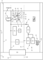
- FIG. 1 An example of a railway vehicle 10 is illustrated in the figure 1 .
- the vehicle 10 comprises at least one car 12, for example a plurality of cars 12.
- the figure 1 illustrates for example at least two cars 12.
- the vehicle 10 includes a traction system, not illustrated, capable of generating the mechanical energy necessary to ensure the movement of the vehicle 10.
- the vehicle 10 comprises an electrical power system 14, a main compressed air line 16, a compressed air production unit 18, a general compressed air braking line 20, a general pressure control system 22 , and at least one braking control system 24 of the vehicle 10.
- the vehicle 10 comprises a plurality of braking control systems 24, each car 12 comprising at least one of the braking control systems 24.
- the vehicle 10 also includes a pneumatic control system 26 of the main pressure of the main pipe 16.
- the vehicle 10 also includes, for example, a control and management system TCMS (in English “Train Control and management System”), not illustrated, capable of actively monitoring the state of the braking functions of the vehicle 10.
- TCMS in English “Train Control and management System”
- Each car 12 includes at least one bogie not illustrated.
- Each bogie carries at least one axle, each axle includes two wheels and a transverse axle.
- the traction system of the railway vehicle 10 is capable of rotating each axle to move the vehicle 10 forward.
- At least one of the cars 12 comprises at least one pneumatic consumer 28 not dedicated to braking and connected to the main pipe 16.
- Each pneumatic consumer 28 not dedicated to braking is capable of presenting an operating configuration, during which the pneumatic consumer 28 consumes compressed air to implement a non-braking function.
- the electrical power system 14 is capable of providing electrical power.
- the electrical power system 14 is known to those skilled in the art and will not be described in more detail below.
- the electrical power supplied is used in particular by the various consumers 28 of the vehicle 10.
- the air production unit 18 is for example located in the or one of the cars 12 of the railway vehicle 10.
- the air production unit 18 is capable of generating compressed air from a power supply supplied by the power supply system 14.
- the production unit 18 is capable of supplying compressed air to the main pipe 16.
- the air production unit 18 comprises at least one compressor not illustrated.
- the or each compressor is capable of taking air from outside the vehicle 10 and transmitting it to the main pipe 16, in a known manner.
- the main compressed air line 16 presents a main pressure.
- the nominal main pressure is for example between 7 bar and 10 bar.
- the main pressure is provided by the air production unit 18.
- the main pipe 16 is intended to supply each pneumatic consumer 28 not dedicated to braking, as well as certain elements of the braking control system 24 as described below.
- the main pipe 16 extends for example over the length of the railway vehicle 10. In particular, it is understood that the main pipe 16 extends over all the cars 12 of the vehicle 10.
- the general braking line 20 comprises for example one section per car 12 of the vehicle 10.
- Two sections of two adjacent cars 12 are for example connected pneumatically by hoses.
- the hoses can be decoupled to allow separation of cars 12.
- the general pressure control system 22 is capable of supplying compressed air to the general braking line 20, in particular from the compressed air of the main line 16.
- the general pressure control system 22 is capable of regulating the supply of compressed air to the general braking line 20, for example via a control member not illustrated.
- the general braking line 20 is distinct from the main line 16.
- the general braking line 20 is capable of transmitting a braking instruction from the driver to the entire railway vehicle 10.
- the general braking pipe 20 extends over the length of the railway vehicle 10.
- the general braking line 20 extends over all the cars 12 of the vehicle 10.
- the general line 20 thus runs through the vehicle 10 from end to end.
- the general braking line 20 comprises for example one section per car 12 of the vehicle 10.
- Two sections of two adjacent cars 12 are for example connected pneumatically by hoses.
- the hoses can be decoupled to allow separation of cars 12.
- the general braking pipe 20 has a so-called general pressure and is supplied, via said control member not illustrated, by the general pressure control system 22.
- the control unit can be operated by the driver.
- the control body is for example a mechanic's valve.
- Other control bodies are known to those skilled in the art and will not be described here.
- the control member is capable of varying the general pressure in the general pipe 20 from 0 bar to a predetermined maximum general pressure.
- the predetermined maximum general pressure is for example greater than or equal to 4 bar, for example equal to 5 bar.
- the general braking line 20 is capable of transmitting pressure variations necessary to control braking.
- the driver of the railway vehicle 10 adjusts his braking by adjusting the general pressure, via the control member.
- Each braking control system 24 of the railway vehicle 10 is capable of automatically triggering braking as a function of the general pressure of the general pipe 20.
- each braking control system 24 comprises, in known manner, a compressed air braking reservoir 30, at least one pneumatic brake 32 and a distribution system 34.
- the brake reservoir 30 is supplied with compressed air via the main pipe 16, preferably via a non-return valve 36.
- Each pneumatic brake 32 is capable of being supplied by a braking pressure supplied by the braking reservoir 30, and is capable of exerting a braking force on the vehicle 10 as a function of the braking pressure supplied.
- the braking force exerted depends on said supplied braking pressure.
- Each pneumatic brake 32 includes a brake cylinder 38.
- Each brake cylinder 38 comprises, for example, a piston connected to a brake pad.
- the brake pad is able to come into contact with an element of one of the wheels of the car 12 to brake the vehicle 10.
- the piston moves according to the change in air pressure in the brake cylinder 38, that is to say according to said supplied brake pressure.
- the distribution system 34 is capable of automatically authorizing the supply of pressure to the or each pneumatic brake 32 from the braking reservoir 30, as a function of the general pressure of the general pipe 20.
- the distribution system 34 comprises at least one distribution valve 40 and a relay valve 42.
- the distribution valve 40 is then capable of controlling the relay valve 42 to automatically authorize the supply of pressure to the or each pneumatic brake 32 from the braking reservoir 30, as a function of the general pressure of the general pipe 20.
- Said supply is for example authorized automatically when the general pressure of the general braking line 20 falls below a general pressure threshold.
- the braking control system 24 is thus capable of controlling braking according to an inverted braking control law: an increase in general pressure reduces braking and a decrease increases braking.
- the general braking line 20 is supplied at a pressure of 5 bars.
- the brakes are applied and exert the braking force.
- a reduction in general pressure in the general braking line 20 is for example caused by a braking command from the driver, an emergency command by one of the passengers of the vehicle 10 by means of an emergency system intended for the passengers, or even a rupture of the general pipe 20.
- braking is automatic to the extent that it is the absence of energy in its control (whether electric or pneumatic) which produces the most conservative result, namely the application of braking.
- Braking is preferably also continuous.
- the general braking line 20 controls in this preferred example all the brake assemblies (distributor, brake cylinder) present on each car 12 of the vehicle 10.
- the vehicle 10 comprises said pneumatic control system 26 of the main pressure of the main pipe 16 which will now be describe.
- the pneumatic control system 26 is capable of automatically comparing the main pressure of the main line 16 with at least the general pressure of the main line 20.
- this is the comparison of the main pressure of the main pipe 16 with at least the sum of the general pressure of the general pipe 20 and the elastic return 49 described in more detail below.
- the pneumatic control system 26 is capable of automatically evacuating the compressed air from the general pipe 20 out of the general pipe 20, when the main pressure of the main pipe 16 falls below a main emergency pressure threshold .
- the pneumatic control system 26 is removable relative to the general pipe 20 and the main pipe 16. It is thus capable of being connected to said pipes 16, 20 only when necessary.
- vehicle 10 requires only one pneumatic control system 26 as described.
- the pneumatic control system 26 of the main pressure preferably comprises at least one comparator distributor 44.
- the pneumatic control system 26 also includes, for example, a flow reducer 46 and an evacuation distributor 48.
- the comparator distributor 44 is a pneumatically operated pneumatic distributor with elastic return 49.
- the elastic return 49 is applied by a spring.
- the spring is preferably adjustable.
- the elastic return 49 enters into the control of the position of the comparator distributor 44.
- the comparator distributor 44 has at least one pneumatic supply inlet connected to the general pipe 20 and at least one pneumatic exhaust outlet connected to the outside air.
- the comparator distributor 44 also has a first control input connected to the main pipe 16 and a second control input connected to the general pipe 20.
- the pneumatic control system 26 comprises a main branch 50 having an inlet directly connected to the main pipe 16 and an outlet directly connected to the first control input of the comparator distributor 44.
- the pneumatic control system 26 comprises a first general branch 52 having an inlet pneumatically connected to the general pipe 20 and an output directly connected to the second control input of the comparator distributor 44.
- the pneumatic control system 26 comprises a second general branch 54 having an inlet pneumatically connected to the general pipe 20 and an outlet directly connected to the pneumatic supply inlet of the comparator distributor 44.
- the comparator distributor 44 has at least one open position, in which the pneumatic supply inlet is placed in fluid communication with the pneumatic exhaust outlet, and a closed position, in which the pneumatic supply inlet does not communicate with pneumatic exhaust outlet.
- the comparator distributor 44 is illustrated in the open position.
- the comparator distributor 44 is for example a 2/2 distributor.
- the elastic return 49 of the comparator distributor 44 is determined so that, when the main pressure of the main pipe 16 falls below a main emergency pressure threshold, the comparator distributor 44 goes into the open position.
- the main emergency pressure threshold is greater than or equal to the minimum pressure to implement braking by all of the pneumatic brakes 32 of the vehicle 10.
- the flow reducer 46 is here interposed between the second control input of the comparator distributor 44 and the general braking pipe 20.
- the flow reducer 46 is arranged on said second general branch 54 (i.e. the branch having its outlet connected to the pneumatic supply inlet of the comparator distributor 44).
- the flow reducer 46 is for example non-adjustable.
- the flow reducer 46 is configured to decouple the pressure levels between the branch 54 and the branch 56 when opening the comparator distributor 44.
- the exhaust through the outlet of the comparator distributor 44 has a predetermined flow rate sufficient to cancel the compensation of the filling flow rate of the branch 54 passing through the flow reducer 46.
- the evacuation distributor 48 is a pneumatically operated pneumatic distributor with elastic return.
- the evacuation distributor 48 has at least one pneumatic supply inlet connected to the general pipe 20 and at least one pneumatic exhaust outlet connected to the outside air.
- the evacuation distributor 48 also has a first control input connected to the general pipe 20 and a second control input connected to a tapping point 55 on said second general branch 54.
- the tapping point 55 is for example interposed between the flow reducer 46 and the pneumatic supply inlet of the comparator distributor 44.
- the pneumatic control system 26 comprises a third general branch 56 having an inlet pneumatically connected to the general pipe 20 and an outlet directly connected to the first control input of the evacuation distributor 48.
- the pneumatic control system 26 comprises a fourth general branch 58 having an inlet pneumatically connected to the general pipe 20 and an outlet directly connected to the pneumatic supply inlet of the evacuation distributor 48.
- the evacuation distributor 48 has at least one open position, in which the pneumatic supply inlet is placed in fluid communication with the pneumatic exhaust outlet of the evacuation distributor 48, and a closed position, in which the Pneumatic supply inlet does not communicate with the pneumatic exhaust outlet.
- the discharge distributor 48 is illustrated in the closed position.
- the evacuation distributor 48 is for example a 2/2 distributor.
- the third and fourth general branches connect to a tapping point upstream of the flow reducer 46.
- the flow in the third and fourth general branches is not influenced by the flow reducer 46.
- the exhaust has a predetermined flow rate greater than the predetermined flow rate of the comparator distributor 44 open.
- Said predetermined flow rate of the evacuation distributor 48 is for example greater than the leakage compensation flow rate of the general pipe 20 of the general pressure control system 22.
- the spring return of the evacuation distributor 48 is determined so that, when the pressures of the first and second control inputs are equal, the evacuation distributor 48 is in the closed position.
- the elastic return of the evacuation distributor 48 is determined so that, when the pressure of the first control inlet of the distributor 48 is greater than the pressure of the second control inlet of the distributor 48, the evacuation distributor 48 is in position opened.
- the comparator distributor 44 switches to the open position. Via the flow reducer 46, an imbalance is created between the pressures of the first and second control inputs of the evacuation distributor 48 which causes the evacuation distributor 48 to move into the open position.
- the general pipe 20 is then placed in fluid communication with the outside air and is emptied.
- the pneumatic control system 26 of the main pressure comprises an isolation valve 60.
- the isolation valve 60 is interposed between the second control input of the comparator distributor 44 and the general braking line 20.
- the isolation valve 60 can be manually actuated between an air passage authorization configuration and an air passage prohibition configuration.
- the isolation valve 60 makes it possible not to use the control system 26, for example in the case where it is not necessary to use it in a nominal situation.
- control system does not have such an isolation valve 60.
- a method of towing a railway vehicle 10 towed by another towing railway vehicle 62 will now be described, the towed vehicle 10 corresponding to the vehicle 10 described above.
- the method is for example implemented for a rescue operation of the towed vehicle 10.
- the towed vehicle 10 is for example in a faulty state.
- At least the compressed air production unit 18 of the towed vehicle 10 is incapable of supplying compressed air to the main pipe 16 of the towed vehicle 10.
- the electrical power system 14 of the vehicle towed 10 has broken down, and is unable to provide electrical power to the compressed air production unit 18.
- the TCMS control and management system is faulty.
- the traction system of the towed vehicle 10 is for example incapable of ensuring the movement of the vehicle 10.
- the traction system of the towed vehicle 10 is incapable of rotating the axles to move the vehicle 10 forward.
- the towed vehicle 10 requires the towing vehicle 62 to move. In other words, the entire towed vehicle 10 and the towing vehicle 62 is moved solely by the traction system of the towing vehicle 62.
- the towing vehicle 62 comprises at least one electrical power system, a main compressed air pipe 64, a compressed air production unit, a general compressed air braking pipe 66, a general pressure control system and a system for controlling the braking of the towing vehicle 62.
- the method includes a step of connecting the respective main pipes 16, 64 of the towed railway vehicles 10 and tug 62, and a step of connecting the respective general braking pipes 20, 66 of the towed railway vehicles 10 and tug 62.
- connections are for example implemented by means of a known dedicated interface 68.
- the main pipe 16 of the towed vehicle 10 is then supplied with main pressure by the main pipe 64 of the towing vehicle 62.
- the general braking line 20 of the towed vehicle 10 is thus supplied with general pressure by the general line 66 of the towing vehicle 62.
- the method comprises a step of connecting the pneumatic control system 26 to the general pipe 20 and to the main pipe 16 of the towed vehicle 10, the system 26 being previously away from said pipes 16, 20.
- the method includes a step of towing the towed vehicle 10 by the towing vehicle 62.
- the towing step includes moving the entire towed vehicle 10 and the towing vehicle 62 by the traction system of the towing vehicle 62.
- the towed vehicle 10 is pushed by the towing vehicle 62.
- the towing step also includes controlling the main pressure of the main pipe 16 of the towed vehicle 10 by the pneumatic control system 26.
- This control is implemented at least during said movement of the entire towed vehicle 10 and the towing vehicle 62.
- the pneumatic control system 26 automatically compares the main pressure of the main line 16 with at least the general pressure of the main line 20.
- this is the comparison of the main pressure of the main pipe 16 with at least the sum of the general pressure of the general pipe 20 and the elastic return 49.
- the pneumatic control system 26 automatically discharges the compressed air of the main line 20 out of the main line 20.
- the braking of the towed vehicle 10 is thus caused automatically by the braking control system 24 of the towed vehicle 10.
- the towing vehicle 62 is also braked by the reaction of its braking control system which reacts to the change in pressure of the general pipe 66 connected and continues to the general pipe 20 of the towed vehicle 10.
- an automatic emergency braking action via the general braking pipe 20 is implemented when the pressure of the main pipe 16 becomes too low, that is to say below which we loses the ability to apply at least one emergency braking by the towed vehicle 10.
- the invention remains simple in that it is not necessary to develop it on each braking reservoir 30, as in the case of the first solution.
- the invention also gives more freedom in its use, to the extent that the pneumatic control system 26 can be considered as a mobile and removable device, to be installed only during an emergency operation.
- the invention also complies with standards EN 14198 and EN 16185-1, imposing as a constraint that the compressed air from the reservoirs of the braking system and the general braking pipe 20 is not used for any purpose other than braking. In fact, these standards do not require that the compressed air from the general braking line 20 and from each braking reservoir 30 be used exclusively to provide power to the braking actuators.
- the solution of the invention uses the air from the main braking line 20 to trigger emergency braking under a pressure threshold in the main line 16. The purpose of the compressed air used in this solution is therefore exclusively linked to braking.
Landscapes
- Engineering & Computer Science (AREA)
- Transportation (AREA)
- Mechanical Engineering (AREA)
- Valves And Accessory Devices For Braking Systems (AREA)
- Braking Systems And Boosters (AREA)
Claims (10)
- Schienenfahrzeug (10), umfassend:- ein Stromversorgungssystem (14);- eine Hauptleitung (16) für Druckluft mit einem Hauptdruck;- eine Drucklufterzeugungseinheit (18), die dazu geeignet ist, Druckluft aus einer elektrischen Versorgung zu erzeugen, die vom Stromversorgungssystem (14) geliefert wird; und die Drucklufterzeugungseinheit ist dazu geeignet, die Hauptleitung (16) mit Druckluft zu versorgen;- eine allgemeine Druckluftbremsleitung (20) mit einem allgemeinen Druck;- ein allgemeines Druckkontrollsystem (22), das dazu geeignet ist, die allgemeine Leitung (20) mit Druckluft aus der Hauptleitung (16) zu versorgen;- mindestens ein Bremssteuersystem (24) des Schienenfahrzeugs (10), das geeignet ist, die Bremsung automatisch in Abhängigkeit vom allgemeinen Druck der allgemeinen Leitung (20) auszulösen, wobei das Bremssteuersystem (24) umfasst:* einen Bremsbehälter (30) für Druckluft, wobei der Bremsbehälter (30) durch die Hauptleitung (16) mit Druckluft versorgt wird,* eine pneumatische Bremse (32), wobei die pneumatische Bremse (32) geeignet ist, mit einem Bremsdruck versorgt zu werden, der von dem Bremsbehälter (30) geliefert wird, und geeignet ist, eine Bremskraft des Fahrzeugs (10) in Abhängigkeit von dem versorgten Bremsdruck auszuüben;* ein Verteilersystem (34), das geeignet ist, die Druckversorgung der oder jeder pneumatischen Bremse (32) aus dem Bremsbehälter (30) in Abhängigkeit vom allgemeinen Druck in der allgemeinen Leitung (20) automatisch zuzulassen;dadurch gekennzeichnet, dass das Schienenfahrzeug (10) ferner ein pneumatisches Steuersystem (26) für den Hauptdruck der Hauptleitung (16) umfasst, wobei das pneumatische Steuersystem (26) dazu geeignet ist, den Hauptdruck der Hauptleitung (16) automatisch mit mindestens dem allgemeinen Druck der allgemeinen Leitung (20) zu vergleichen, und geeignet ist, automatisch Druckluft aus der allgemeinen Leitung (20) abzulassen, wenn der Hauptdruck der Hauptleitung (16) unter einen Hauptnotdruckschwellenwert fällt.
- Schienenfahrzeug (10) nach Anspruch 1, wobei das Fahrzeug (10) eine Vielzahl von Bremssteuersystemen (24) umfasst und der Hauptnotdruckschwellenwert größer oder gleich dem Mindestdruck ist, um eine Bremsung durch die Gesamtheit der Druckluftbremsen (32) des Fahrzeugs (10) zu implementieren.
- Schienenfahrzeug (10) nach einem der Ansprüche 1 oder 2, wobei das pneumatische Hauptdruck-Steuersystem (26) mindestens ein Komparatorventil (44) umfasst, wobei das Komparatorventil (44) ein pneumatisches Ventil mit elastischer Rückstellung (49) ist, wobei das Komparatorventil (44) mindestens einen mit der allgemeinen Leitung (20) verbundenen pneumatischen Versorgungseingang umfasst und mindestens einen mit der Außenluft verbundenen pneumatischen Ablassausgang aufweist. Das Komparatorventil (44) hat einen ersten Steuereingang, der mit der Hauptleitung (16) verbunden ist, und einen zweiten Steuereingang, der mit der allgemeinen Leitung (20) verbunden ist. Das pneumatische Steuersystem (26) ist vorzugsweise dazu geeignet, den Hauptdruck der Hauptleitung (16) automatisch mit mindestens der Summe aus dem allgemeinen Druck der allgemeinen Leitung (20) und der elastischen Rückstellung (49) zu vergleichen.
- Schienenfahrzeug (10) nach Anspruch 3, wobei das pneumatische Steuersystem (26) für den Hauptdruck einen allgemeinen Zweig (54) mit einem Einlass umfasst, der pneumatisch mit der allgemeinen Bremsleitung (20) verbunden ist, und einen Ausgang, der direkt mit dem pneumatischen Versorgungseingang des Komparatorventils (44) verbunden ist, wobei das pneumatische Steuersystem (26) für den Hauptdruck auch einen Durchflussreduzierer (46) umfasst, der an dem allgemeinen Zweig (54) angeordnet ist und zwischen dem Hauptdruckregler (26) und zwischen dem zweiten Steuereingang des Komparatorventils (44) und der allgemeinen Bremsleitung (20), wobei der Durchflussreduzierer (46) zum Beispiel nicht einstellbar ist.
- Schienenfahrzeug (10) nach Anspruch 4, wobei das pneumatische Hauptdruck-Steuersystem (26) mindestens ein Ablassventil (48) umfasst, wobei das Ablassventil (48) ein pneumatisch gesteuertes pneumatisches Ventil mit elastischer Rückstellung ist, wobei das Ablassventil (48) mindestens einen pneumatischen Versorgungseingang aufweist, der mit der allgemeinen Leitung (20) verbunden ist, und mindestens einen pneumatischen Auslass, der mit der Außenluft verbunden ist, wobei das Ablassventil (48) einen ersten Steuereingang aufweist, der mit der allgemeinen Leitung (20) verbunden ist, und einen zweiten Steuereingang, der mit einem Abzweigpunkt (55) an dem allgemeinen Zweig (54) verbunden ist.
- Schienenfahrzeug (10) nach einem der Ansprüche 3 bis 5, wobei das pneumatische Steuersystem (26) für den Hauptdruck ein Absperrventil (60) umfasst, das zwischen dem zweiten Steuereingang des Komparatorventils (44) und der allgemeinen Bremsleitung (20) angeordnet ist, wobei das Absperrventil (60) manuell zwischen einer Konfiguration, in der der Luftdurchgang erlaubt ist, und einer Konfiguration, in der der Luftdurchgang verboten ist, betätigbar ist.
- Schienenfahrzeug (10) nach einem der vorhergehenden Ansprüche, bei dem das Verteilersystem (34) ein Verteilerventil (40) und ein Relaisventil (42) umfasst, wobei das Verteilerventil (40) dazu geeignet ist das Relaisventil (42) zu steuern, um automatisch die Druckversorgung der oder jeder pneumatischen Bremse (32) aus dem Bremsbehälter (30) in Abhängigkeit vom allgemeinen Druck in der allgemeinen Leitung (20) zuzulassen.
- Schienenfahrzeug (10) nach einem der vorhergehenden Ansprüche, bei dem das Verteilersystem (34) dazu geeignet ist, automatisch die Druckversorgung der oder jeder pneumatischen Bremse (32) aus dem Bremsbehälter (30) zuzulassen, wenn der allgemeine Druck in der allgemeinen Bremsleitung (20) unter einen allgemeinen Druckschwellenwert abfällt.
- Schienenfahrzeug (10) nach einem der vorhergehenden Ansprüche, wobei das pneumatische Steuersystem (26) von der allgemeinen Leitung (20) und der Hauptleitung (16) abnehmbar ist.
- Verfahren zum Abschleppen eines Schienenfahrzeugs (10), das von einem anderen schleppenden Schienenfahrzeug (62) abgeschleppt wird,wobei das abgeschleppte Schienenfahrzeug (10) nach einem der vorhergehenden Ansprüche das abgeschleppte Fahrzeug (10) in einem defekten Zustand ist, in dem zumindest die Drucklufterzeugungseinheit (18) nicht in der Lage ist, die Hauptleitung (16) des abgeschleppten Fahrzeugs (10) mit Druckluft zu versorgen,das Abschleppfahrzeug (62) mindestens eine Hauptleitung (64) und eine allgemeine Bremsleitung (66) umfasst,Wobei das Verfahren die folgenden Schritte umfasst:- Verbindung der jeweiligen Hauptleitungen (16, 64) der abgeschleppten (10) und abschleppenden (62) Schienenfahrzeuge;- Verbindung der jeweiligen allgemeinen Bremsleitungen (20, 66) der abgeschleppten (10) und abschleppenden (62) Schienenfahrzeuge;- Abschleppen des abgeschleppten Fahrzeugs (10) durch das abschleppende Fahrzeug (62), dadurch gekennzeichnet, dass der Schritt des Abschleppens mindestens das Überwachen des Hauptdrucks der Hauptleitung (16) des abgeschleppten Fahrzeugs (10) durch das pneumatische Steuersystem (26) umfasst.
Applications Claiming Priority (1)
| Application Number | Priority Date | Filing Date | Title |
|---|---|---|---|
| FR2113840A FR3130726B1 (fr) | 2021-12-17 | 2021-12-17 | Véhicule ferroviaire et méthode de remorquage associée |
Publications (2)
| Publication Number | Publication Date |
|---|---|
| EP4197867A1 EP4197867A1 (de) | 2023-06-21 |
| EP4197867B1 true EP4197867B1 (de) | 2024-03-13 |
Family
ID=80735883
Family Applications (1)
| Application Number | Title | Priority Date | Filing Date |
|---|---|---|---|
| EP22213690.5A Active EP4197867B1 (de) | 2021-12-17 | 2022-12-15 | Schienenfahrzeug und entsprechendes abschleppverfahren |
Country Status (2)
| Country | Link |
|---|---|
| EP (1) | EP4197867B1 (de) |
| FR (1) | FR3130726B1 (de) |
Family Cites Families (3)
| Publication number | Priority date | Publication date | Assignee | Title |
|---|---|---|---|---|
| US6062653A (en) * | 1998-04-13 | 2000-05-16 | Westinghouse Air Brake Company | Brake valve system for dedicated freight cars |
| CN107235041A (zh) * | 2017-06-16 | 2017-10-10 | 中车长春轨道客车股份有限公司 | 轨道车辆救援紧急制动同步控制电路及控制方法 |
| CN109878489B (zh) * | 2019-04-10 | 2021-06-29 | 南京中车浦镇海泰制动设备有限公司 | 一种动车组回送或救援用指令转换控制电路 |
-
2021
- 2021-12-17 FR FR2113840A patent/FR3130726B1/fr active Active
-
2022
- 2022-12-15 EP EP22213690.5A patent/EP4197867B1/de active Active
Also Published As
| Publication number | Publication date |
|---|---|
| EP4197867A1 (de) | 2023-06-21 |
| FR3130726A1 (fr) | 2023-06-23 |
| FR3130726B1 (fr) | 2023-12-22 |
Similar Documents
| Publication | Publication Date | Title |
|---|---|---|
| CA3015544C (fr) | Systeme de freinage ferroviaire pour vehicule ferroviaire et procede de freinage d'un vehicule ferroviaire comportant un tel systeme | |
| CA3015705C (fr) | Systeme de freinage ferroviaire pour vehicule ferroviaire et procede de freinage d'un vehicule ferroviaire comportant un tel systeme | |
| FR2492754A1 (fr) | Installation alimentee en energie exterieure, pour la regulation du glissement de freinage d'un systeme de freinage hydraulique d'un vehicule automobile | |
| EP4197867B1 (de) | Schienenfahrzeug und entsprechendes abschleppverfahren | |
| EP3820748B1 (de) | Verbessertes hydraulisches notbremsverfahren und schaltung für kupplung | |
| FR3080818A1 (fr) | Systeme de freinage ameliore et vehicule comportant un tel systeme de freinage | |
| EP2102049B1 (de) | Kraftfahrzeugbremsanordnung | |
| EP3609754B1 (de) | Vereinfachtes führerbremsventil und pneumatischer bremskreis eines schienenfahrzeugs mit einem solchen führerbremsventil | |
| EP3934953B1 (de) | Schienenbremssystem mit einer parkbremsanzeigevorrichtung und schienenfahrzeug mit einem solchen system | |
| EP3934952B1 (de) | Eisenbahnbremssystem mit einer betriebsbremsanzeigevorrichtung und schienenfahrzeug mit einem solchen system | |
| EP3609753B1 (de) | Vereinfachtes führerbremsventil und pneumatischer bremskreis eines schienenfahrzeugs mit einem solchen führerbremsventil | |
| EP0091348B1 (de) | Reglerventil für gleichzeitige Speisung hydraulischer Anlagen mit offener und geschlossener Mitte | |
| EP1827940B1 (de) | Bremsvorrichtung für ein industriefahrzeug | |
| EP3795447A1 (de) | Sicherungs-schnittstellensystem zwischen zwei verschiedenen schienenfahrzeugen, entsprechendes schienenfahrzeug und verfahren | |
| EP0115991B1 (de) | Fahrzeugschmierölpumpe | |
| EP1968836B1 (de) | Bremsvorrichtung für ein nutzfahrzeug | |
| FR2681387A1 (fr) | Valve de commande de pression de fluide. | |
| BE478224A (de) | ||
| FR2804733A1 (fr) | Procede et dispositif de distribution de pression et valves pour leur mise en oeuvre | |
| FR2728851A1 (fr) | Limiteur de surcharge du reservoir de commande d'un distributeur de freinage ferroviaire |
Legal Events
| Date | Code | Title | Description |
|---|---|---|---|
| PUAI | Public reference made under article 153(3) epc to a published international application that has entered the european phase |
Free format text: ORIGINAL CODE: 0009012 |
|
| STAA | Information on the status of an ep patent application or granted ep patent |
Free format text: STATUS: THE APPLICATION HAS BEEN PUBLISHED |
|
| AK | Designated contracting states |
Kind code of ref document: A1 Designated state(s): AL AT BE BG CH CY CZ DE DK EE ES FI FR GB GR HR HU IE IS IT LI LT LU LV MC ME MK MT NL NO PL PT RO RS SE SI SK SM TR |
|
| STAA | Information on the status of an ep patent application or granted ep patent |
Free format text: STATUS: REQUEST FOR EXAMINATION WAS MADE |
|
| 17P | Request for examination filed |
Effective date: 20230619 |
|
| RBV | Designated contracting states (corrected) |
Designated state(s): AL AT BE BG CH CY CZ DE DK EE ES FI FR GB GR HR HU IE IS IT LI LT LU LV MC ME MK MT NL NO PL PT RO RS SE SI SK SM TR |
|
| GRAP | Despatch of communication of intention to grant a patent |
Free format text: ORIGINAL CODE: EPIDOSNIGR1 |
|
| STAA | Information on the status of an ep patent application or granted ep patent |
Free format text: STATUS: GRANT OF PATENT IS INTENDED |
|
| INTG | Intention to grant announced |
Effective date: 20231017 |
|
| GRAS | Grant fee paid |
Free format text: ORIGINAL CODE: EPIDOSNIGR3 |
|
| GRAA | (expected) grant |
Free format text: ORIGINAL CODE: 0009210 |
|
| STAA | Information on the status of an ep patent application or granted ep patent |
Free format text: STATUS: THE PATENT HAS BEEN GRANTED |
|
| AK | Designated contracting states |
Kind code of ref document: B1 Designated state(s): AL AT BE BG CH CY CZ DE DK EE ES FI FR GB GR HR HU IE IS IT LI LT LU LV MC ME MK MT NL NO PL PT RO RS SE SI SK SM TR |
|
| REG | Reference to a national code |
Ref country code: GB Ref legal event code: FG4D Free format text: NOT ENGLISH |
|
| REG | Reference to a national code |
Ref country code: CH Ref legal event code: EP |
|
| REG | Reference to a national code |
Ref country code: DE Ref legal event code: R096 Ref document number: 602022002364 Country of ref document: DE |
|
| REG | Reference to a national code |
Ref country code: IE Ref legal event code: FG4D Free format text: LANGUAGE OF EP DOCUMENT: FRENCH |