EP4197864A1 - Smart key system for automobile - Google Patents
Smart key system for automobile Download PDFInfo
- Publication number
- EP4197864A1 EP4197864A1 EP22204124.6A EP22204124A EP4197864A1 EP 4197864 A1 EP4197864 A1 EP 4197864A1 EP 22204124 A EP22204124 A EP 22204124A EP 4197864 A1 EP4197864 A1 EP 4197864A1
- Authority
- EP
- European Patent Office
- Prior art keywords
- resin
- automobile
- strength
- resin case
- key system
- Prior art date
- Legal status (The legal status is an assumption and is not a legal conclusion. Google has not performed a legal analysis and makes no representation as to the accuracy of the status listed.)
- Granted
Links
Images


Classifications
-
- B—PERFORMING OPERATIONS; TRANSPORTING
- B60—VEHICLES IN GENERAL
- B60R—VEHICLES, VEHICLE FITTINGS, OR VEHICLE PARTS, NOT OTHERWISE PROVIDED FOR
- B60R25/00—Fittings or systems for preventing or indicating unauthorised use or theft of vehicles
- B60R25/20—Means to switch the anti-theft system on or off
- B60R25/24—Means to switch the anti-theft system on or off using electronic identifiers containing a code not memorised by the user
-
- B—PERFORMING OPERATIONS; TRANSPORTING
- B60—VEHICLES IN GENERAL
- B60R—VEHICLES, VEHICLE FITTINGS, OR VEHICLE PARTS, NOT OTHERWISE PROVIDED FOR
- B60R16/00—Electric or fluid circuits specially adapted for vehicles and not otherwise provided for; Arrangement of elements of electric or fluid circuits specially adapted for vehicles and not otherwise provided for
- B60R16/02—Electric or fluid circuits specially adapted for vehicles and not otherwise provided for; Arrangement of elements of electric or fluid circuits specially adapted for vehicles and not otherwise provided for electric constitutive elements
-
- B—PERFORMING OPERATIONS; TRANSPORTING
- B60—VEHICLES IN GENERAL
- B60R—VEHICLES, VEHICLE FITTINGS, OR VEHICLE PARTS, NOT OTHERWISE PROVIDED FOR
- B60R25/00—Fittings or systems for preventing or indicating unauthorised use or theft of vehicles
-
- B—PERFORMING OPERATIONS; TRANSPORTING
- B60—VEHICLES IN GENERAL
- B60R—VEHICLES, VEHICLE FITTINGS, OR VEHICLE PARTS, NOT OTHERWISE PROVIDED FOR
- B60R25/00—Fittings or systems for preventing or indicating unauthorised use or theft of vehicles
- B60R25/20—Means to switch the anti-theft system on or off
- B60R25/2072—Means to switch the anti-theft system on or off with means for preventing jamming or interference of a remote switch control signal
-
- B—PERFORMING OPERATIONS; TRANSPORTING
- B60—VEHICLES IN GENERAL
- B60R—VEHICLES, VEHICLE FITTINGS, OR VEHICLE PARTS, NOT OTHERWISE PROVIDED FOR
- B60R25/00—Fittings or systems for preventing or indicating unauthorised use or theft of vehicles
- B60R25/20—Means to switch the anti-theft system on or off
- B60R25/24—Means to switch the anti-theft system on or off using electronic identifiers containing a code not memorised by the user
- B60R25/246—Means to switch the anti-theft system on or off using electronic identifiers containing a code not memorised by the user characterised by the challenge triggering
-
- B—PERFORMING OPERATIONS; TRANSPORTING
- B60—VEHICLES IN GENERAL
- B60R—VEHICLES, VEHICLE FITTINGS, OR VEHICLE PARTS, NOT OTHERWISE PROVIDED FOR
- B60R25/00—Fittings or systems for preventing or indicating unauthorised use or theft of vehicles
- B60R25/20—Means to switch the anti-theft system on or off
- B60R25/24—Means to switch the anti-theft system on or off using electronic identifiers containing a code not memorised by the user
- B60R25/248—Electronic key extraction prevention
-
- G—PHYSICS
- G07—CHECKING-DEVICES
- G07C—TIME OR ATTENDANCE REGISTERS; REGISTERING OR INDICATING THE WORKING OF MACHINES; GENERATING RANDOM NUMBERS; VOTING OR LOTTERY APPARATUS; ARRANGEMENTS, SYSTEMS OR APPARATUS FOR CHECKING NOT PROVIDED FOR ELSEWHERE
- G07C9/00—Individual registration on entry or exit
- G07C9/00174—Electronically operated locks; Circuits therefor; Nonmechanical keys therefor, e.g. passive or active electrical keys or other data carriers without mechanical keys
- G07C9/00309—Electronically operated locks; Circuits therefor; Nonmechanical keys therefor, e.g. passive or active electrical keys or other data carriers without mechanical keys operated with bidirectional data transmission between data carrier and locks
-
- G—PHYSICS
- G07—CHECKING-DEVICES
- G07C—TIME OR ATTENDANCE REGISTERS; REGISTERING OR INDICATING THE WORKING OF MACHINES; GENERATING RANDOM NUMBERS; VOTING OR LOTTERY APPARATUS; ARRANGEMENTS, SYSTEMS OR APPARATUS FOR CHECKING NOT PROVIDED FOR ELSEWHERE
- G07C9/00—Individual registration on entry or exit
- G07C9/00174—Electronically operated locks; Circuits therefor; Nonmechanical keys therefor, e.g. passive or active electrical keys or other data carriers without mechanical keys
- G07C2009/00753—Electronically operated locks; Circuits therefor; Nonmechanical keys therefor, e.g. passive or active electrical keys or other data carriers without mechanical keys operated by active electrical keys
- G07C2009/00769—Electronically operated locks; Circuits therefor; Nonmechanical keys therefor, e.g. passive or active electrical keys or other data carriers without mechanical keys operated by active electrical keys with data transmission performed by wireless means
-
- G—PHYSICS
- G07—CHECKING-DEVICES
- G07C—TIME OR ATTENDANCE REGISTERS; REGISTERING OR INDICATING THE WORKING OF MACHINES; GENERATING RANDOM NUMBERS; VOTING OR LOTTERY APPARATUS; ARRANGEMENTS, SYSTEMS OR APPARATUS FOR CHECKING NOT PROVIDED FOR ELSEWHERE
- G07C2209/00—Indexing scheme relating to groups G07C9/00 - G07C9/38
- G07C2209/60—Indexing scheme relating to groups G07C9/00174 - G07C9/00944
- G07C2209/63—Comprising locating means for detecting the position of the data carrier, i.e. within the vehicle or within a certain distance from the vehicle
Definitions
- the present disclosure relates to a smart key system for an automobile.
- Patent Literature 1 discloses a smart key system for an automobile.
- the smart key system disclosed in Patent Literature 1 includes an on-vehicle device and a portable device capable of wirelessly communicating with the on-vehicle device.
- Patent Literature 1 there is a case where as the radio signal transmitted from the on-vehicle device is increased, a resin case of the on-vehicle device and a resin panel through which the on-vehicle device is fixed to and held by the body of the vehicle are electrostatically charged.
- the resin case of the on-vehicle device and the resin panel through which the on-vehicle device is fixed to and held by the body of the vehicle are electrostatically charged, the strength of the noise signals contained in the radio signal received from the portable device is increased, so that the strength of the radio signal transmitted from the on-vehicle device is further increased and hence the resin case and the resin panel are electrostatically charged even further.
- the vehicle When the amount of electrostatic charging in the resin case and the resin panel increases, the vehicle may not exhibit its normal traveling performance due to the increased amount of electrostatic charging.
- the present disclosure has been made in order to solve the above-described problem, and an object thereof is to provide a smart key system for an automobile capable of preventing or reducing the deterioration of the performance of the vehicle (i.e., the automobile) which would otherwise be caused by electrostatic charging of a resin case of an on-vehicle device and a resin panel through which the on-vehicle device is fixed to and held by the body of the automobile.
- a first exemplary aspect is a smart key system for an automobile, including: an on-vehicle device configured to transmit and receive a radio signal to and from an electronic key; and a resin panel through which the on-vehicle device is fixed to and held by a body of the automobile, in which the on-vehicle device includes:
- the control unit may increase a strength of the search signal when a strength of the response signal received by the receiver is equal to or smaller than a predetermined strength, when a strength of a noise signal contained in the response signal is equal to or larger than the predetermined strength, or when the strength of the response signal is equal to or smaller than a predetermined strength and the strength of the noise signal is equal to larger than the predetermined strength.
- the resin case and the resin panel are electrostatically charged more easily, so that the present disclosure is particularly effective.
- At least one of the resin case and the resin panel, and the body of the automobile electrically connected to a negative electrode of an auxiliary battery may be connected to a ground, so that electrostatic charging may be removed from them.
- electrostatic charging can be efficiently removed from the resin case, the resin panel, or both of them.
- At least one of the resin case and the resin panel, and the body of the automobile including an electrostatic-charging removing device may be connected to a ground, so that electrostatic charging may be removed from them.
- At least one of the resin case and the resin panel may include a surfactant layer for the removal of the electrostatic charging on an exterior surface thereof.
- At least one of the resin case and the resin panel may include an elastic film containing a surfactant for the removal of the electrostatic charging on an exterior surface thereof.
- At least one of the resin case and the resin panel may include an elastic mesh sheet containing a surfactant for the removal of the electrostatic charging on an exterior surface thereof.
- a smart key system for an automobile capable of preventing or reducing the deterioration of the performance of the vehicle (i.e., the automobile) which would otherwise be caused by electrostatic charging of a resin case of an on-vehicle device and electrostatic charging of a resin panel through which the on-vehicle device is fixed to and held by the body of the vehicle.
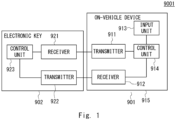
- Fig. 1 is a block diagram showing a configuration of a key system for an automobile according to related art.
- a key system 9001 for an automobile enables a user carrying an electronic key to carry out predetermined operations and thereby to use various functions provided in the automobile.
- Examples of combinations of predetermined operations and functions provided in automobiles include unlocking of a door of an automobile by depressing a button provided on the door, and starting-up of an engine by depressing an engine start button.
- the key system 9001 for the automobile includes an on-vehicle device 901 and an electronic key 902.
- the on-vehicle device 901 includes a transmitter 911, a receiver 912, an input unit 913, a control unit 914, and a resin case 915.
- the transmitter 911 transmits a search signal, which is a radio signal, to the electronic key 902 under the control of the control unit 914.
- the receiver 912 receives a response signal transmitted from the electronic key 902 in response to the search signal.
- the receiver 912 Upon receiving the response signal, the receiver 912 outputs authentication information contained in the response signal to the control unit 914.
- the input unit 913 is, for example, a door unlock button or an engine start button, and is a device on which a user performs a predetermined operation.
- the input unit 913 When the predetermined operation is performed on the input unit 913 by the user, the input unit 913 notifies the control unit 914 that the predetermined operation has been performed thereon.
- control unit 914 When the control unit 914 is notified, by the input unit 913, that the user has performed the predetermined operation, the control unit 914 controls the transmitter 911, and thereby makes (e.g., instructs) the transmitter 911 transmit a search signal.
- control unit 914 acquires, from the input unit 913, the authentication information contained in the response signal transmitted from the electronic key 902, the control unit 914 determines whether or not the acquired authentication information is the same as authentication information that is registered in advance. When the authentication information is the same as the one registered in advance, the control unit 914 notifies the control apparatus, which controls a predetermined function, that a function corresponding to the predetermined operation performed by the user should be carried out.
- the control unit 914 does not perform the determination and instead controls the transmitter 911 so that the transmitter 911 transmits a search signal having a strength higher than that of the previous search signal.
- control unit 914 includes, for example, an arithmetic unit such as a CPU (Central Processing Unit) (not shown), and a storage unit such as a RAM (Random Access Memory) and a ROM (Read Only Memory) in which programs and data for controlling the on-vehicle device 901 are stored. That is, the control unit 914 has functions as a computer and controls the on-vehicle device 901 based on the aforementioned program.
- arithmetic unit such as a CPU (Central Processing Unit) (not shown)
- storage unit such as a RAM (Random Access Memory) and a ROM (Read Only Memory) in which programs and data for controlling the on-vehicle device 901 are stored. That is, the control unit 914 has functions as a computer and controls the on-vehicle device 901 based on the aforementioned program.
- the resin case 915 is a case made of resin that houses therein the transmitter 911, the receiver 912, the input unit 913, and the control unit 914.
- the resin case 915 is fixed to and held by the vehicle (i.e., the automobile), for example, through a resin panel provided in the body of the vehicle.
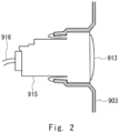
- Fig. 2 is a schematic cross-sectional diagram showing a resin case and a resin panel in the case where the input unit 913 is an engine start button.
- a resin panel 903 is a resin panel provided in front of the driver's seat inside the vehicle, and a hole in which an on-vehicle device 1 is fitted (i.e., inserted) is formed.
- the resin case 915 is fitted (i.e., inserted) into the hole of the resin panel 903, so that resin case 915 is fixed to and held by the body of the vehicle.
- a cable 916 is a cable for connecting the control unit 914 of the on-vehicle device 901 to an ECU (Engine Control Unit) of the engine.
- the control unit 914 requests the ECU of the engine to start up the engine through the cable 916.
- the electronic key 902 includes a receiver 921, a transmitter 922, and a control unit 923.
- the receiver 921 When the receiver 921 receives a search signal from the on-vehicle device 901, the receiver 921 notifies the control unit 923 of the reception of the search signal.
- the transmitter 922 transmits a response signal, which is a radio signal, to the on-vehicle device 901 under the control of the control unit 923.
- the control unit 923 Upon receiving the information indicating the reception of the search signal from the receiver 921, the control unit 923 controls the transmitter 922 and thereby makes (e.g., instructs) the transmitter 922 transmit a response signal containing authentication information. Note that the control unit 923 determines the strength of the response signal based on the strength of the received search signal. Specifically, the control unit 923 controls the transmitter 922 in such a manner that the higher the strength of the search signal is, the stronger response signal the transmitter 922 transmits.
- control unit 923 includes, for example, an arithmetic unit such as a CPU (Central Processing Unit) (not shown), and a storage unit such as a RAM (Random Access Memory) and a ROM (Read Only Memory) in which programs and data for controlling the electronic key 902 are stored. That is, the control unit 923 has functions as a computer and controls the electronic key 902 based on the aforementioned program.
- arithmetic unit such as a CPU (Central Processing Unit) (not shown)
- storage unit such as a RAM (Random Access Memory) and a ROM (Read Only Memory) in which programs and data for controlling the electronic key 902 are stored. That is, the control unit 923 has functions as a computer and controls the electronic key 902 based on the aforementioned program.
- the on-vehicle device 901 transmits a search signal having a higher strength.
- the resin case 915 and the resin panel 903 are electrostatically charged.
- the electrostatic charging of the resin case 915 and the resin panel 903 causes noise signals in the response signal received by the on-vehicle device 901, and hence causes a further increase in the strength of the search signal and resulting larger electrostatic charging of the resin case 915 and the resin panel 903.
- At least one of the resin case and the resin panel, and the body of the vehicle electrically connected to a negative electrode of an auxiliary battery are connected to the ground, so that electrostatic charging is removed from either or both of the resin case and the resin panel.
- At least one of the resin case and the resin panel includes an electrostatic-charging removing surfactant layer on an exterior surface thereof, so that electrostatic charging is removed from at least one of the resin case and the resin panel by the electrostatic-charging removing surfactant layer.
- Fig. 3 is a block diagram showing a configuration of a key system for an automobile according to a first embodiment.
- a key system 1001 for an automobile enables a user carrying an electronic key to carry out predetermined operations and thereby to use various functions provided in the automobile.
- Examples of combinations of predetermined operations and functions provided in automobiles include unlocking of a door of the automobile by depressing a button provided on the door and starting-up of an engine by depressing an engine start button.
- the key system 1001 for the automobile according to the first embodiment includes an on-vehicle device 1, an electronic key 2, and a resin panel 3.
- the on-vehicle device 1 includes a transmitter 11, a receiver 12, an input unit 13, a control unit 14, and a resin case 15.
- the transmitter 11 transmits a search signal, which is a radio signal, to the electronic key 2 under the control of the control unit 14.
- the receiver 12 receives a response signal transmitted from the electronic key 2 in response to the search signal.
- the receiver 12 Upon receiving the response signal, the receiver 12 outputs authentication information contained in the response signal to the control unit 14.
- the input unit 13 is, for example, a door unlock button or an engine start button, and is a device that receives a predetermined operation from a user. Upon receiving the predetermined operation from the user, the input unit 13 notifies the control unit 14 of the reception of the predetermined operation.
- control unit 14 When the control unit 14 is notified, by the input unit 13, that the user has performed the predetermined operation, the control unit 14 controls the transmitter 11, and thereby makes (e.g., instructs) the transmitter 11 transmit a search signal.
- control unit 14 acquires, from the input unit 13, the authentication information contained in the response signal transmitted from the electronic key 2, the control unit 14 determines whether or not the acquired authentication information is the same as authentication information that is registered in advance. When the authentication information is the same as the one registered in advance, the control unit 14 notifies the control apparatus, which controls a predetermined function, that a function corresponding to the predetermined operation performed by the user should be carried out.
- the control unit 14 does not perform the determination and instead controls the transmitter 11 so that the transmitter 11 transmits a search signal having a strength higher than that of the previous search signal.
- control unit 14 includes, for example, an arithmetic unit such as a CPU (Central Processing Unit) (not shown), and a storage unit such as a RAM (Random Access Memory) and a ROM (Read Only Memory) in which programs and data for controlling the on-vehicle device 1 are stored. That is, the control unit 14 has functions as a computer and controls the on-vehicle device 1 based on the aforementioned program.
- arithmetic unit such as a CPU (Central Processing Unit) (not shown)
- storage unit such as a RAM (Random Access Memory) and a ROM (Read Only Memory) in which programs and data for controlling the on-vehicle device 1 are stored. That is, the control unit 14 has functions as a computer and controls the on-vehicle device 1 based on the aforementioned program.
- the resin case 15 is a case made of resin that houses therein the transmitter 11, the receiver 12, the input unit 13, and the control unit 14.
- the resin case 15 is fixed to and held by the vehicle (i.e., the automobile) through the resin panel 3.
- the resin case 15 is electrostatically charged as the strength of the search signal transmitted from the transmitter 11 increases.
- the electronic key 2 includes a receiver 21, a transmitter 22, and a control unit 23.
- the receiver 21 When the receiver 21 receives a search signal from the on-vehicle device 1, the receiver 21 notifies the control unit 23 of the reception of the search signal.
- the transmitter 22 transmits a response signal, which is a radio signal, to the on-vehicle device 1 under the control of the control unit 23.
- the control unit 23 Upon receiving the information indicating the reception of the search signal from the receiver 21, the control unit 23 controls the transmitter 22 and thereby makes (e.g., instructs) the transmitter 22 transmit a response signal containing authentication information. Note that the control unit 23 determines the strength of the response signal based on the strength of the received search signal. Specifically, the control unit 23 controls the transmitter 22 so that the higher the strength of the search signal is, the stronger response signal the transmitter 22 transmits.
- control unit 23 includes, for example, an arithmetic unit such as a CPU (Central Processing Unit) (not shown), and a storage unit such as a RAM (Random Access Memory) and a ROM (Read Only Memory) in which programs and data for controlling the electronic key 2 are stored. That is, the control unit 23 has functions as a computer and controls the electronic key 2 based on the aforementioned program.
- arithmetic unit such as a CPU (Central Processing Unit) (not shown)
- storage unit such as a RAM (Random Access Memory) and a ROM (Read Only Memory) in which programs and data for controlling the electronic key 2 are stored. That is, the control unit 23 has functions as a computer and controls the electronic key 2 based on the aforementioned program.
- the resin panel 3 is a panel made of resin through which the on-vehicle device 1 is fixed to and held by the body of the vehicle.
- the resin panel 903 is a resin panel provided in front of the driver's seat inside the vehicle, and a hole in which the on-vehicle device 1 is fitted (i.e., inserted) is formed.
- the resin panel 3 is electrostatically charged as the strength of the search signal transmitted from the transmitter 11 increases.
- At least one of the resin case 15 and the resin panel 3, and the body of the automobile electrically connected to a negative electrode of an auxiliary battery are connected to the ground.
- the auxiliary battery has a function of removing electrostatic charging from the body of the automobile, so that, by the above-described configuration, electrostatic charging is removed from either or both of the resin case 15 and the resin panel 3. As a result, it is possible to prevent or reduce the deterioration of the performance of the vehicle (i.e., the automobile) which would otherwise be caused by electrostatic charging of the resin case 15 and the resin panel 3.
- At least one of the resin case 15 and the resin panel 3, and the body of the automobile including an electrostatic-charging removing device may be connected to the ground.
- the electrostatic-charging removing device is preferably disposed, for example, in a metal frame such as a body frame, a brake pedal mounting frame, and a steering column frame.
- at least one of the resin case 15 and the resin panel 3 is preferably connected directly to the ground, i.e., directly connected to the metal frame in which the electrostatic-charging removing device is disposed.
- Examples of the electrostatic-charging removing device include air ionization self-discharging type aluminum foil adhesive tape or the like.
- the key system for the automobile according to the first embodiment can prevent or reduce the deterioration of the performance of the vehicle (i.e., the automobile).
- a smart key system for an automobile according to a second embodiment has a configuration similar to that of the key system for an automobile according to the first embodiment.
- electrostatic charging is removed from at least one of the electrostatically-charged resin case 15 and the resin panel 3 through the connection between the body of the automobile and the ground.
- electrostatic charging is removed from at least one of the electrostatically-charged resin case 15 and the resin panel 3 by an electrostatic-charging removing surfactant layer provided on the surface thereof.
- At least one of the resin case 15 and the resin panel 3 according to this embodiment includes an electrostatic-charging removing surfactant layer on the exterior surface thereof.
- the electrostatic-charging removing surfactant layer may be formed by, for example, spraying an electrostatic-charging removing surfactant on the exterior surfaces of the resin case 15 and/or the resin panel 3.
- a cationic surfactant As the electrostatic-charging removing surfactant, a cationic surfactant, an anionic surfactant, an amphoteric ion-based surfactant, a non-ionic surfactant, or a mixture thereof may be used. Among them, the cationic surfactant is particularly preferred because of its high electrostatic-charging removing property.
- the electrostatic-charging removing surfactant contains a hydrophilic group, so that it has a high affinity with water molecules. Therefore, the surface of the electrostatic-charging removing surfactant layer is strongly bound to water molecules. Since water molecules bonded to the electrostatic-charging removing surfactant remove static electricity, the electrostatic charging of the resin case 15 and the resin panel 3 are removed by the electrostatic-charging removing surfactant layer.
- At least one of the resin case and the resin panel may include an elastic film containing an electrostatic-charging removing surfactant on the exterior surface thereof.
- the resin case and the resin panel may include an elastic film containing an electrostatic-charging removing surfactant, they may or may not include an electrostatic-charging removing surfactant layer.
- At least one of the resin case and the resin panel may include an elastic mesh sheet containing an electrostatic-charging removing surfactant on the exterior surface thereof.
- the resin case and the resin panel may include an elastic mesh sheet containing an electrostatic-charging removing surfactant, they may or may not include an electrostatic-charging removing surfactant layer.
- Fig. 4 is a schematic cross-sectional diagram showing an example of a resin case and a resin panel including an elastic mesh sheet containing an electrostatic-charging removing surfactant on the exterior surface thereof, and is a schematic cross-sectional diagram in the case where the input unit 13 is an engine start button.
- an elastic mesh sheet 4 is an elastic mesh sheet containing an electrostatic-charging removing surfactant
- a cable 16 is a cable for connecting the control unit 14 of the on-vehicle device 1 to an ECU of an engine.
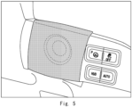
- Fig. 5 is a figure showing an example of a resin case and a resin panel including an elastic mesh sheet containing an electrostatic-charging removing surfactant on the exterior surface thereof, and is a figure in the case where the input unit 13 is an engine start button.
- the smart key system for an automobile according to the second embodiment electrostatic charging is removed from at least one of the resin case 15 and the resin panel 3 by the electrostatic-charging removing surfactant layer provided on the exterior surface of at least one of the resin case 15 and the resin panel 3.
- the smart key system for an automobile according to the second embodiment can prevent or reduce the deterioration of the performance of the vehicle (i.e., the automobile).
Landscapes
- Engineering & Computer Science (AREA)
- Mechanical Engineering (AREA)
- Computer Networks & Wireless Communication (AREA)
- Physics & Mathematics (AREA)
- General Physics & Mathematics (AREA)
- Lock And Its Accessories (AREA)
- Transceivers (AREA)
- Transmitters (AREA)
Abstract
Description
- The present disclosure relates to a smart key system for an automobile.
-
Japanese Unexamined Patent Application Publication No. 2017-057627 - In the smart key system disclosed in Patent Literature 1, there is a case where as the radio signal transmitted from the on-vehicle device is increased, a resin case of the on-vehicle device and a resin panel through which the on-vehicle device is fixed to and held by the body of the vehicle are electrostatically charged. When the resin case of the on-vehicle device and the resin panel through which the on-vehicle device is fixed to and held by the body of the vehicle are electrostatically charged, the strength of the noise signals contained in the radio signal received from the portable device is increased, so that the strength of the radio signal transmitted from the on-vehicle device is further increased and hence the resin case and the resin panel are electrostatically charged even further.
- When the amount of electrostatic charging in the resin case and the resin panel increases, the vehicle may not exhibit its normal traveling performance due to the increased amount of electrostatic charging.
- The present disclosure has been made in order to solve the above-described problem, and an object thereof is to provide a smart key system for an automobile capable of preventing or reducing the deterioration of the performance of the vehicle (i.e., the automobile) which would otherwise be caused by electrostatic charging of a resin case of an on-vehicle device and a resin panel through which the on-vehicle device is fixed to and held by the body of the automobile.
- A first exemplary aspect is a smart key system for an automobile, including: an on-vehicle device configured to transmit and receive a radio signal to and from an electronic key; and a resin panel through which the on-vehicle device is fixed to and held by a body of the automobile, in which
the on-vehicle device includes: - a transmitter configured to transmit a search signal to the electronic key;
- a receiver configured to receive a response signal transmitted from the electronic key in response to the search signal;
- a control unit configured to control at least the transmission of the search signal; and
- a resin case configured to house therein the transmitter, the receiver, and the control unit, and
- electrostatic charging generated by the search signal transmitted from the transmitter is removed from either or both of the resin case and the resin panel.
- By the above-described configuration, it is possible to prevent or reduce the deterioration of the performance of the vehicle (i.e., the automobile) which would otherwise be caused by electrostatic charging of a resin case of an on-vehicle device and electrostatic charging of a resin panel through which the on-vehicle device is fixed to and held by the body of the vehicle.
- In an aspect, in the smart key system for an automobile, the control unit may increase a strength of the search signal when a strength of the response signal received by the receiver is equal to or smaller than a predetermined strength, when a strength of a noise signal contained in the response signal is equal to or larger than the predetermined strength, or when the strength of the response signal is equal to or smaller than a predetermined strength and the strength of the noise signal is equal to larger than the predetermined strength.
- In the case where the control unit controls the search signal as described above, the resin case and the resin panel are electrostatically charged more easily, so that the present disclosure is particularly effective.
- In an aspect, in the smart key system for an automobile, at least one of the resin case and the resin panel, and the body of the automobile electrically connected to a negative electrode of an auxiliary battery may be connected to a ground, so that electrostatic charging may be removed from them.
- By the above-described configuration, electrostatic charging can be efficiently removed from the resin case, the resin panel, or both of them.
- In an aspect, in the smart key system for an automobile, at least one of the resin case and the resin panel, and the body of the automobile including an electrostatic-charging removing device may be connected to a ground, so that electrostatic charging may be removed from them.
- Even by the above-described configuration, electrostatic charging can be efficiently removed from the resin case, the resin panel, or both of them.
- In an aspect, in the smart key system for an automobile, at least one of the resin case and the resin panel may include a surfactant layer for the removal of the electrostatic charging on an exterior surface thereof.
- Even by the above-described configuration, electrostatic charging can be efficiently removed from the resin case, the resin panel, or both of them.
- In an aspect, in the smart key system for an automobile, at least one of the resin case and the resin panel may include an elastic film containing a surfactant for the removal of the electrostatic charging on an exterior surface thereof.
- Even by the above-described configuration, electrostatic charging can be efficiently removed from the resin case, the resin panel, or both of them.
- In an aspect, in the smart key system for an automobile, at least one of the resin case and the resin panel may include an elastic mesh sheet containing a surfactant for the removal of the electrostatic charging on an exterior surface thereof.
- Even by the above-described configuration, electrostatic charging can be efficiently removed from the resin case, the resin panel, or both of them.
- According to the present disclosure, it is possible to provide a smart key system for an automobile capable of preventing or reducing the deterioration of the performance of the vehicle (i.e., the automobile) which would otherwise be caused by electrostatic charging of a resin case of an on-vehicle device and electrostatic charging of a resin panel through which the on-vehicle device is fixed to and held by the body of the vehicle.
- The above and other objects, features and advantages of the present disclosure will become more fully understood from the detailed description given hereinbelow and the accompanying drawings which are given by way of illustration only, and thus are not to be considered as limiting the present disclosure.
-
-
Fig. 1 is a block diagram showing a configuration of a smart key system according to related art; -
Fig. 2 is a schematic cross-sectional diagram showing a configuration of a resin case and a resin panel according to the related art; -
Fig. 3 is a block diagram showing a configuration of a smart key system according to a first embodiment; -
Fig. 4 is a schematic cross-sectional diagram showing an example of a resin case and a resin panel including an elastic mesh sheet containing an electrostatic-charging removing surfactant on an exterior surface; and -
Fig. 5 is a photograph showing an example of a resin case and a resin panel including an elastic mesh sheet containing an electrostatic-charging removing surfactant on an exterior surface thereof. -
Fig. 1 is a block diagram showing a configuration of a key system for an automobile according to related art. - A
key system 9001 for an automobile according to the related art enables a user carrying an electronic key to carry out predetermined operations and thereby to use various functions provided in the automobile. - Examples of combinations of predetermined operations and functions provided in automobiles include unlocking of a door of an automobile by depressing a button provided on the door, and starting-up of an engine by depressing an engine start button.
- The
key system 9001 for the automobile according to the related art includes an on-vehicle device 901 and anelectronic key 902. - The on-
vehicle device 901 includes atransmitter 911, areceiver 912, aninput unit 913, acontrol unit 914, and aresin case 915. - The
transmitter 911 transmits a search signal, which is a radio signal, to theelectronic key 902 under the control of thecontrol unit 914. Thereceiver 912 receives a response signal transmitted from theelectronic key 902 in response to the search signal. - Upon receiving the response signal, the
receiver 912 outputs authentication information contained in the response signal to thecontrol unit 914. - The
input unit 913 is, for example, a door unlock button or an engine start button, and is a device on which a user performs a predetermined operation. - When the predetermined operation is performed on the
input unit 913 by the user, theinput unit 913 notifies thecontrol unit 914 that the predetermined operation has been performed thereon. - When the
control unit 914 is notified, by theinput unit 913, that the user has performed the predetermined operation, thecontrol unit 914 controls thetransmitter 911, and thereby makes (e.g., instructs) thetransmitter 911 transmit a search signal. - Further, when the
control unit 914 acquires, from theinput unit 913, the authentication information contained in the response signal transmitted from theelectronic key 902, thecontrol unit 914 determines whether or not the acquired authentication information is the same as authentication information that is registered in advance. When the authentication information is the same as the one registered in advance, thecontrol unit 914 notifies the control apparatus, which controls a predetermined function, that a function corresponding to the predetermined operation performed by the user should be carried out. - Note that when the strength of the response signal received from the
electronic key 902 is equal to or smaller than a predetermined strength, when the strength of a noise signal contained in the response signal is equal to or larger than a predetermined strength, or when the strength of the response signal is equal to or smaller than the predetermined strength and the strength of the noise signal is equal to larger than the predetermined strength, thecontrol unit 914 does not perform the determination and instead controls thetransmitter 911 so that thetransmitter 911 transmits a search signal having a strength higher than that of the previous search signal. - Further, the
control unit 914 includes, for example, an arithmetic unit such as a CPU (Central Processing Unit) (not shown), and a storage unit such as a RAM (Random Access Memory) and a ROM (Read Only Memory) in which programs and data for controlling the on-vehicle device 901 are stored. That is, thecontrol unit 914 has functions as a computer and controls the on-vehicle device 901 based on the aforementioned program. - The
resin case 915 is a case made of resin that houses therein thetransmitter 911, thereceiver 912, theinput unit 913, and thecontrol unit 914. Theresin case 915 is fixed to and held by the vehicle (i.e., the automobile), for example, through a resin panel provided in the body of the vehicle. -
Fig. 2 is a schematic cross-sectional diagram showing a resin case and a resin panel in the case where theinput unit 913 is an engine start button. - A
resin panel 903 is a resin panel provided in front of the driver's seat inside the vehicle, and a hole in which an on-vehicle device 1 is fitted (i.e., inserted) is formed. - The
resin case 915 is fitted (i.e., inserted) into the hole of theresin panel 903, so thatresin case 915 is fixed to and held by the body of the vehicle. - A
cable 916 is a cable for connecting thecontrol unit 914 of the on-vehicle device 901 to an ECU (Engine Control Unit) of the engine. Thecontrol unit 914 requests the ECU of the engine to start up the engine through thecable 916. - The
electronic key 902 includes areceiver 921, atransmitter 922, and acontrol unit 923. - When the
receiver 921 receives a search signal from the on-vehicle device 901, thereceiver 921 notifies thecontrol unit 923 of the reception of the search signal. - The
transmitter 922 transmits a response signal, which is a radio signal, to the on-vehicle device 901 under the control of thecontrol unit 923. - Upon receiving the information indicating the reception of the search signal from the
receiver 921, thecontrol unit 923 controls thetransmitter 922 and thereby makes (e.g., instructs) thetransmitter 922 transmit a response signal containing authentication information. Note that thecontrol unit 923 determines the strength of the response signal based on the strength of the received search signal. Specifically, thecontrol unit 923 controls thetransmitter 922 in such a manner that the higher the strength of the search signal is, the stronger response signal thetransmitter 922 transmits. - Further, the
control unit 923 includes, for example, an arithmetic unit such as a CPU (Central Processing Unit) (not shown), and a storage unit such as a RAM (Random Access Memory) and a ROM (Read Only Memory) in which programs and data for controlling theelectronic key 902 are stored. That is, thecontrol unit 923 has functions as a computer and controls theelectronic key 902 based on the aforementioned program. - As described above, when the strength of the response signal received from the
electronic key 902 is equal to or smaller than a predetermined strength, when the strength of a noise signal contained in the response signal is equal to or larger than a predetermined strength, or when the strength of the response signal is equal to or smaller than the predetermined strength and the strength of the noise signal is equal to larger than the predetermined strength, the on-vehicle device 901 transmits a search signal having a higher strength. The higher the strength of the search signal is, the stronger response signal theelectronic key 902 transmits. By the above-described configuration, the on-vehicle device 901 can receive a response signal having an appropriate strength. - However, in the
key system 9001 for an automobile according to the related art, there are cases where as the strength of the search signal increases, theresin case 915 and theresin panel 903 are electrostatically charged. The electrostatic charging of theresin case 915 and theresin panel 903 causes noise signals in the response signal received by the on-vehicle device 901, and hence causes a further increase in the strength of the search signal and resulting larger electrostatic charging of theresin case 915 and theresin panel 903. - As a result of diligent study, the inventors have found that electrostatic charging of the
resin case 915 and theresin panel 903 causes the processing speed of the control apparatus of the vehicle to decrease, so that the performance of the vehicle is impaired. - As a result of further study, the inventors have found that it is possible to prevent or reduce the deterioration of the performance of the vehicle by removing electrostatic charging of the resin case and the resin panel.
- Therefore, in a first embodiment, at least one of the resin case and the resin panel, and the body of the vehicle electrically connected to a negative electrode of an auxiliary battery are connected to the ground, so that electrostatic charging is removed from either or both of the resin case and the resin panel.
- Further, in a second embodiment, at least one of the resin case and the resin panel includes an electrostatic-charging removing surfactant layer on an exterior surface thereof, so that electrostatic charging is removed from at least one of the resin case and the resin panel by the electrostatic-charging removing surfactant layer.
-
Fig. 3 is a block diagram showing a configuration of a key system for an automobile according to a first embodiment. - A
key system 1001 for an automobile according to the first embodiment enables a user carrying an electronic key to carry out predetermined operations and thereby to use various functions provided in the automobile. - Examples of combinations of predetermined operations and functions provided in automobiles include unlocking of a door of the automobile by depressing a button provided on the door and starting-up of an engine by depressing an engine start button.
- The
key system 1001 for the automobile according to the first embodiment includes an on-vehicle device 1, anelectronic key 2, and aresin panel 3. - The on-vehicle device 1 includes a
transmitter 11, areceiver 12, aninput unit 13, acontrol unit 14, and aresin case 15. - The
transmitter 11 transmits a search signal, which is a radio signal, to theelectronic key 2 under the control of thecontrol unit 14. Thereceiver 12 receives a response signal transmitted from theelectronic key 2 in response to the search signal. - Upon receiving the response signal, the
receiver 12 outputs authentication information contained in the response signal to thecontrol unit 14. - The
input unit 13 is, for example, a door unlock button or an engine start button, and is a device that receives a predetermined operation from a user. Upon receiving the predetermined operation from the user, theinput unit 13 notifies thecontrol unit 14 of the reception of the predetermined operation. - When the
control unit 14 is notified, by theinput unit 13, that the user has performed the predetermined operation, thecontrol unit 14 controls thetransmitter 11, and thereby makes (e.g., instructs) thetransmitter 11 transmit a search signal. - Further, when the
control unit 14 acquires, from theinput unit 13, the authentication information contained in the response signal transmitted from theelectronic key 2, thecontrol unit 14 determines whether or not the acquired authentication information is the same as authentication information that is registered in advance. When the authentication information is the same as the one registered in advance, thecontrol unit 14 notifies the control apparatus, which controls a predetermined function, that a function corresponding to the predetermined operation performed by the user should be carried out. - Note that when the strength of the response signal received from the
electronic key 2 is equal to or smaller than a predetermined strength, when the strength of a noise signal contained in the response signal is equal to or larger than a predetermined strength, or when the strength of the response signal is equal to or smaller than the predetermined strength and the strength of the noise signal is equal to larger than the predetermined strength, thecontrol unit 14 does not perform the determination and instead controls thetransmitter 11 so that thetransmitter 11 transmits a search signal having a strength higher than that of the previous search signal. - Further, the
control unit 14 includes, for example, an arithmetic unit such as a CPU (Central Processing Unit) (not shown), and a storage unit such as a RAM (Random Access Memory) and a ROM (Read Only Memory) in which programs and data for controlling the on-vehicle device 1 are stored. That is, thecontrol unit 14 has functions as a computer and controls the on-vehicle device 1 based on the aforementioned program. - The
resin case 15 is a case made of resin that houses therein thetransmitter 11, thereceiver 12, theinput unit 13, and thecontrol unit 14. Theresin case 15 is fixed to and held by the vehicle (i.e., the automobile) through theresin panel 3. - The
resin case 15 is electrostatically charged as the strength of the search signal transmitted from thetransmitter 11 increases. - The
electronic key 2 includes areceiver 21, atransmitter 22, and acontrol unit 23. - When the
receiver 21 receives a search signal from the on-vehicle device 1, thereceiver 21 notifies thecontrol unit 23 of the reception of the search signal. - The
transmitter 22 transmits a response signal, which is a radio signal, to the on-vehicle device 1 under the control of thecontrol unit 23. - Upon receiving the information indicating the reception of the search signal from the
receiver 21, thecontrol unit 23 controls thetransmitter 22 and thereby makes (e.g., instructs) thetransmitter 22 transmit a response signal containing authentication information. Note that thecontrol unit 23 determines the strength of the response signal based on the strength of the received search signal. Specifically, thecontrol unit 23 controls thetransmitter 22 so that the higher the strength of the search signal is, the stronger response signal thetransmitter 22 transmits. - Further, the
control unit 23 includes, for example, an arithmetic unit such as a CPU (Central Processing Unit) (not shown), and a storage unit such as a RAM (Random Access Memory) and a ROM (Read Only Memory) in which programs and data for controlling theelectronic key 2 are stored. That is, thecontrol unit 23 has functions as a computer and controls theelectronic key 2 based on the aforementioned program. - The
resin panel 3 is a panel made of resin through which the on-vehicle device 1 is fixed to and held by the body of the vehicle. For example, when theinput unit 13 is an engine start button, theresin panel 903 is a resin panel provided in front of the driver's seat inside the vehicle, and a hole in which the on-vehicle device 1 is fitted (i.e., inserted) is formed. - The
resin panel 3 is electrostatically charged as the strength of the search signal transmitted from thetransmitter 11 increases. - In the smart key system for an automobile according to the first embodiment, at least one of the
resin case 15 and theresin panel 3, and the body of the automobile electrically connected to a negative electrode of an auxiliary battery are connected to the ground. - The auxiliary battery has a function of removing electrostatic charging from the body of the automobile, so that, by the above-described configuration, electrostatic charging is removed from either or both of the
resin case 15 and theresin panel 3. As a result, it is possible to prevent or reduce the deterioration of the performance of the vehicle (i.e., the automobile) which would otherwise be caused by electrostatic charging of theresin case 15 and theresin panel 3. - In the smart key system for the automobile according to this embodiment, at least one of the
resin case 15 and theresin panel 3, and the body of the automobile including an electrostatic-charging removing device may be connected to the ground. The electrostatic-charging removing device is preferably disposed, for example, in a metal frame such as a body frame, a brake pedal mounting frame, and a steering column frame. Further, at least one of theresin case 15 and theresin panel 3 is preferably connected directly to the ground, i.e., directly connected to the metal frame in which the electrostatic-charging removing device is disposed. Examples of the electrostatic-charging removing device include air ionization self-discharging type aluminum foil adhesive tape or the like. - As described above, in the smart key system for the automobile according to the first embodiment, electrostatic charging is removed from either or both of the electrostatically-charged
resin case 15 and theresin panel 3 through the connection between the body of the vehicle and the ground. By the above-described configuration, the key system for the automobile according to the first embodiment can prevent or reduce the deterioration of the performance of the vehicle (i.e., the automobile). - A smart key system for an automobile according to a second embodiment has a configuration similar to that of the key system for an automobile according to the first embodiment.
- In the first embodiment, electrostatic charging is removed from at least one of the electrostatically-charged
resin case 15 and theresin panel 3 through the connection between the body of the automobile and the ground. In contrast to this, in the second embodiment, electrostatic charging is removed from at least one of the electrostatically-chargedresin case 15 and theresin panel 3 by an electrostatic-charging removing surfactant layer provided on the surface thereof. - At least one of the
resin case 15 and theresin panel 3 according to this embodiment includes an electrostatic-charging removing surfactant layer on the exterior surface thereof. - The electrostatic-charging removing surfactant layer may be formed by, for example, spraying an electrostatic-charging removing surfactant on the exterior surfaces of the
resin case 15 and/or theresin panel 3. - As the electrostatic-charging removing surfactant, a cationic surfactant, an anionic surfactant, an amphoteric ion-based surfactant, a non-ionic surfactant, or a mixture thereof may be used. Among them, the cationic surfactant is particularly preferred because of its high electrostatic-charging removing property.
- The electrostatic-charging removing surfactant contains a hydrophilic group, so that it has a high affinity with water molecules. Therefore, the surface of the electrostatic-charging removing surfactant layer is strongly bound to water molecules. Since water molecules bonded to the electrostatic-charging removing surfactant remove static electricity, the electrostatic charging of the
resin case 15 and theresin panel 3 are removed by the electrostatic-charging removing surfactant layer. - In the smart key system for an automobile according to this embodiment, at least one of the resin case and the resin panel may include an elastic film containing an electrostatic-charging removing surfactant on the exterior surface thereof. Note that in the case where the resin case and the resin panel include an elastic film containing an electrostatic-charging removing surfactant, they may or may not include an electrostatic-charging removing surfactant layer.
- Further, in the smart key system for an automobile according to this embodiment, at least one of the resin case and the resin panel may include an elastic mesh sheet containing an electrostatic-charging removing surfactant on the exterior surface thereof. Note that in the case where the resin case and the resin panel include an elastic mesh sheet containing an electrostatic-charging removing surfactant, they may or may not include an electrostatic-charging removing surfactant layer.
-
Fig. 4 is a schematic cross-sectional diagram showing an example of a resin case and a resin panel including an elastic mesh sheet containing an electrostatic-charging removing surfactant on the exterior surface thereof, and is a schematic cross-sectional diagram in the case where theinput unit 13 is an engine start button. It should be noted that an elastic mesh sheet 4 is an elastic mesh sheet containing an electrostatic-charging removing surfactant, and acable 16 is a cable for connecting thecontrol unit 14 of the on-vehicle device 1 to an ECU of an engine. - Further,
Fig. 5 is a figure showing an example of a resin case and a resin panel including an elastic mesh sheet containing an electrostatic-charging removing surfactant on the exterior surface thereof, and is a figure in the case where theinput unit 13 is an engine start button. - Even by the above-described configuration, electrostatic charging of the
resin case 15 and theresin panel 3 can be removed. - As described above, in the smart key system for an automobile according to the second embodiment, electrostatic charging is removed from at least one of the
resin case 15 and theresin panel 3 by the electrostatic-charging removing surfactant layer provided on the exterior surface of at least one of theresin case 15 and theresin panel 3. By the above-described configuration, the smart key system for an automobile according to the second embodiment can prevent or reduce the deterioration of the performance of the vehicle (i.e., the automobile). - From the disclosure thus described, it will be obvious that the embodiments of the disclosure may be varied in many ways. Such variations are not to be regarded as a departure from the spirit and scope of the disclosure, and all such modifications as would be obvious to one skilled in the art are intended for inclusion within the scope of the following claims.
Claims (7)
- A smart key system for an automobile, comprising: an on-vehicle device (1) configured to transmit and receive a radio signal to and from an electronic key (2); and a resin panel (3) through which the on-vehicle device is fixed to and held by a body of the automobile, wherein
the on-vehicle device (1) comprises:a transmitter (11) configured to transmit a search signal to the electronic key (2);a receiver (12) configured to receive a response signal transmitted from the electronic key (2) in response to the search signal;a control unit (14) configured to control at least the transmission of the search signal; anda resin case (15) configured to house therein the transmitter (11), the receiver (12), and the control unit (14), andelectrostatic charging generated by the search signal transmitted from the transmitter is removed from either or both of the resin case (15) and the resin panel (3). - The smart key system for an automobile according to Claim 1, wherein the control unit (14) increases a strength of the search signal when a strength of the response signal received by the receiver (12) is equal to or smaller than a predetermined strength, when a strength of a noise signal contained in the response signal is equal to or larger than the predetermined strength, or when the strength of the response signal is equal to or smaller than a predetermined strength and the strength of the noise signal is equal to larger than the predetermined strength.
- The smart key system for an automobile according to Claim 1 or 2,
wherein at least one of the resin case (15) and the resin panel (3), and the body of the automobile electrically connected to a negative electrode of an auxiliary battery are connected to a ground, so that electrostatic charging is removed from them. - The smart key system for an automobile according to any one of Claims 1 to 3, wherein at least one of the resin case (15) and the resin panel (3), and the body of the automobile including an electrostatic-charging removing device are connected to a ground, so that electrostatic charging is removed from them.
- The smart key system for an automobile according to any one of Claims 1 to 4, wherein at least one of the resin case (15) and the resin panel (3) includes a surfactant layer for the removal of the electrostatic charging on an exterior surface thereof.
- The smart key system for an automobile according to any one of Claims 1 to 5, wherein at least one of the resin case (15) and the resin panel (3) includes an elastic film containing a surfactant for the removal of the electrostatic charging on an exterior surface thereof.
- The smart key system for an automobile according to any one of Claims 1 to 6, wherein at least one of the resin case (15) and the resin panel (3) includes an elastic mesh sheet containing a surfactant for the removal of the electrostatic charging on an exterior surface thereof.
Applications Claiming Priority (1)
| Application Number | Priority Date | Filing Date | Title |
|---|---|---|---|
| JP2021197305A JP7571715B2 (en) | 2021-12-03 | 2021-12-03 | Automotive smart key systems |
Publications (2)
| Publication Number | Publication Date |
|---|---|
| EP4197864A1 true EP4197864A1 (en) | 2023-06-21 |
| EP4197864B1 EP4197864B1 (en) | 2025-06-18 |
Family
ID=84043754
Family Applications (1)
| Application Number | Title | Priority Date | Filing Date |
|---|---|---|---|
| EP22204124.6A Active EP4197864B1 (en) | 2021-12-03 | 2022-10-27 | Smart key system for automobile |
Country Status (4)
| Country | Link |
|---|---|
| US (1) | US12221064B2 (en) |
| EP (1) | EP4197864B1 (en) |
| JP (1) | JP7571715B2 (en) |
| CN (1) | CN116215442B (en) |
Citations (4)
| Publication number | Priority date | Publication date | Assignee | Title |
|---|---|---|---|---|
| US20030156070A1 (en) * | 2002-02-21 | 2003-08-21 | Toyota Jidosha Kabushiki Kaisha | Vehicular antenna device |
| US20060250731A1 (en) * | 2005-05-03 | 2006-11-09 | Parkhurst Ray M | System and method for electrostatic discharge protection in an electronic circuit |
| EP2400820A1 (en) * | 2009-02-17 | 2011-12-28 | Tooru Nakai | Charge supplier |
| US20170076524A1 (en) * | 2015-09-16 | 2017-03-16 | Toyota Jidosha Kabushiki Kaisha | Smart key system |
Family Cites Families (29)
| Publication number | Priority date | Publication date | Assignee | Title |
|---|---|---|---|---|
| JPH0722943Y2 (en) * | 1991-06-25 | 1995-05-24 | 株式会社本田ロック | Transmitter |
| JP3216112B2 (en) * | 1996-01-31 | 2001-10-09 | 日本精機株式会社 | Vehicle instrumentation |
| JP3130269B2 (en) * | 1997-05-30 | 2001-01-31 | 愛三工業株式会社 | Fuel supply device |
| JPH11297490A (en) * | 1998-04-10 | 1999-10-29 | Daihatsu Motor Co Ltd | Automotive static elimination sheet material |
| JP4161420B2 (en) | 1998-08-04 | 2008-10-08 | マツダ株式会社 | Keyless entry system |
| JP3509790B2 (en) * | 2000-08-09 | 2004-03-22 | アイシン精機株式会社 | Vehicle door lock device |
| JP3719403B2 (en) * | 2001-10-17 | 2005-11-24 | 株式会社デンソー | Transparent resin molding |
| US6919848B2 (en) * | 2002-06-25 | 2005-07-19 | Harada Industry Co., Ltd. | Antenna apparatus for vehicle |
| JP4778264B2 (en) | 2005-04-28 | 2011-09-21 | 株式会社日立製作所 | Wireless IC tag and method of manufacturing wireless IC tag |
| JP2008078971A (en) * | 2006-09-21 | 2008-04-03 | Auto Network Gijutsu Kenkyusho:Kk | In-vehicle wireless receiver and setting method of wireless receiver |
| JP2012005244A (en) * | 2010-06-17 | 2012-01-05 | Denso Corp | On-vehicle electronic control unit device |
| JP5841898B2 (en) * | 2012-05-29 | 2016-01-13 | 日立オートモティブシステムズ株式会社 | On-vehicle electronic device and vehicle equipped with the same |
| JP2015005597A (en) * | 2013-06-20 | 2015-01-08 | 日立オートモティブシステムズ株式会社 | Resin sealed type sensor device |
| JP6117049B2 (en) * | 2013-08-08 | 2017-04-19 | メタウォーター株式会社 | Water treatment system |
| WO2016024742A1 (en) * | 2014-08-09 | 2016-02-18 | LG Display Co.,Ltd. | Rollable organic light emitting diode display device |
| JP6273182B2 (en) * | 2014-08-25 | 2018-01-31 | 株式会社東芝 | Electronics |
| JP6124020B2 (en) * | 2014-08-29 | 2017-05-10 | トヨタ自動車株式会社 | Charged charge reduction device for vehicles |
| US9681542B2 (en) * | 2014-11-14 | 2017-06-13 | Oracle International Corporation | Flexible circuit with partial ground path |
| TWI572106B (en) * | 2015-03-26 | 2017-02-21 | 瑞昱半導體股份有限公司 | Current-mirror-based electrostatic discharge clamping circuit and current-mirror-based electrostatic discharge detector |
| US9349503B1 (en) * | 2015-11-19 | 2016-05-24 | Yun-Chin Teng | Grounding conductive cable structure |
| JP2017183988A (en) | 2016-03-30 | 2017-10-05 | パナソニックIpマネジメント株式会社 | On-vehicle device, smart key system, signal transmission method |
| JP6558313B2 (en) * | 2016-06-29 | 2019-08-14 | トヨタ自動車株式会社 | Vehicle and manufacturing method thereof |
| JP7050600B2 (en) * | 2018-07-09 | 2022-04-08 | トヨタ自動車株式会社 | Static eliminator for vehicles and vehicles |
| JP7225674B2 (en) * | 2018-10-23 | 2023-02-21 | トヨタ自動車株式会社 | coil unit |
| US10923863B2 (en) * | 2018-12-04 | 2021-02-16 | J.S.T. Corporation | High voltage connector and method for assembling thereof |
| CN113632182B (en) * | 2019-03-29 | 2022-12-30 | 株式会社自动网络技术研究所 | Wiring module |
| CN210984952U (en) * | 2019-12-06 | 2020-07-10 | 昇印光电(昆山)股份有限公司 | a transparent antenna |
| JP2021151103A (en) * | 2020-03-19 | 2021-09-27 | 住友電装株式会社 | Wire harness |
| US11989987B2 (en) * | 2021-08-31 | 2024-05-21 | Bauer Products, Inc. | Lock and method for operating same |
-
2021
- 2021-12-03 JP JP2021197305A patent/JP7571715B2/en active Active
-
2022
- 2022-10-27 EP EP22204124.6A patent/EP4197864B1/en active Active
- 2022-10-27 US US18/050,218 patent/US12221064B2/en active Active
- 2022-11-30 CN CN202211527516.2A patent/CN116215442B/en active Active
Patent Citations (5)
| Publication number | Priority date | Publication date | Assignee | Title |
|---|---|---|---|---|
| US20030156070A1 (en) * | 2002-02-21 | 2003-08-21 | Toyota Jidosha Kabushiki Kaisha | Vehicular antenna device |
| US20060250731A1 (en) * | 2005-05-03 | 2006-11-09 | Parkhurst Ray M | System and method for electrostatic discharge protection in an electronic circuit |
| EP2400820A1 (en) * | 2009-02-17 | 2011-12-28 | Tooru Nakai | Charge supplier |
| US20170076524A1 (en) * | 2015-09-16 | 2017-03-16 | Toyota Jidosha Kabushiki Kaisha | Smart key system |
| JP2017057627A (en) | 2015-09-16 | 2017-03-23 | トヨタ自動車株式会社 | Smart key system |
Also Published As
| Publication number | Publication date |
|---|---|
| JP7571715B2 (en) | 2024-10-23 |
| US20230174015A1 (en) | 2023-06-08 |
| JP2023083129A (en) | 2023-06-15 |
| CN116215442B (en) | 2025-04-04 |
| EP4197864B1 (en) | 2025-06-18 |
| US12221064B2 (en) | 2025-02-11 |
| CN116215442A (en) | 2023-06-06 |
Similar Documents
| Publication | Publication Date | Title |
|---|---|---|
| EP2172917B1 (en) | Telematics terminal and method for notifing emergency conditions using the same | |
| US20180012091A1 (en) | Contextual-based display devices and methods of operating the same | |
| US12157480B2 (en) | Method for transferring control over vehicle in automotive electronic system, and apparatus | |
| US10759482B2 (en) | Open-cabin vehicle | |
| CN113386787B (en) | Autonomous vehicles | |
| US11453261B2 (en) | Trailer to vehicle integral current draw management | |
| CN113320508A (en) | Parking brake control method, parking brake controller and electronic parking brake system | |
| EP4197864B1 (en) | Smart key system for automobile | |
| CN105365772B (en) | Remote starter for vehicle controls | |
| US20160170840A1 (en) | Vehicle information backup unit for storing information of telematics unit, mobile terminal, and vehicle information backup system | |
| CN110871764A (en) | System and method for generating and transmitting emergency service requests | |
| US9020724B2 (en) | Electric braking device for vehicles | |
| US11604679B2 (en) | Dynamic workload shifting within a connected vehicle | |
| KR20130046950A (en) | Usb intermediary device for vehicle | |
| US20230316826A1 (en) | Information processing apparatus, computer-readable storage medium, and information processing method | |
| US11539104B2 (en) | Battery pillar protector | |
| CN203132556U (en) | Vehicle information terminal | |
| JP7313507B1 (en) | In-vehicle information processing device | |
| US12552401B2 (en) | Vehicle control system | |
| US10936123B1 (en) | Tactile confirmation for touch screen systems | |
| JP2022131110A (en) | Vehicle with smart key system | |
| WO2025142867A1 (en) | Data collection system, on-vehicle device, management center, data collection method, and program | |
| CN120196129A (en) | Monitoring device | |
| CN119517020A (en) | A voice interaction method, device and storage medium | |
| CN115871647A (en) | Vehicle control device |
Legal Events
| Date | Code | Title | Description |
|---|---|---|---|
| PUAI | Public reference made under article 153(3) epc to a published international application that has entered the european phase |
Free format text: ORIGINAL CODE: 0009012 |
|
| STAA | Information on the status of an ep patent application or granted ep patent |
Free format text: STATUS: REQUEST FOR EXAMINATION WAS MADE |
|
| 17P | Request for examination filed |
Effective date: 20221027 |
|
| AK | Designated contracting states |
Kind code of ref document: A1 Designated state(s): AL AT BE BG CH CY CZ DE DK EE ES FI FR GB GR HR HU IE IS IT LI LT LU LV MC ME MK MT NL NO PL PT RO RS SE SI SK SM TR |
|
| GRAP | Despatch of communication of intention to grant a patent |
Free format text: ORIGINAL CODE: EPIDOSNIGR1 |
|
| STAA | Information on the status of an ep patent application or granted ep patent |
Free format text: STATUS: GRANT OF PATENT IS INTENDED |
|
| RIC1 | Information provided on ipc code assigned before grant |
Ipc: H01L 23/60 20060101ALI20250305BHEP Ipc: G07C 9/00 20200101ALI20250305BHEP Ipc: B60R 25/24 20130101AFI20250305BHEP |
|
| INTG | Intention to grant announced |
Effective date: 20250404 |
|
| GRAS | Grant fee paid |
Free format text: ORIGINAL CODE: EPIDOSNIGR3 |
|
| GRAA | (expected) grant |
Free format text: ORIGINAL CODE: 0009210 |
|
| STAA | Information on the status of an ep patent application or granted ep patent |
Free format text: STATUS: THE PATENT HAS BEEN GRANTED |
|
| AK | Designated contracting states |
Kind code of ref document: B1 Designated state(s): AL AT BE BG CH CY CZ DE DK EE ES FI FR GB GR HR HU IE IS IT LI LT LU LV MC ME MK MT NL NO PL PT RO RS SE SI SK SM TR |
|
| REG | Reference to a national code |
Ref country code: GB Ref legal event code: FG4D |
|
| REG | Reference to a national code |
Ref country code: CH Ref legal event code: EP |
|
| REG | Reference to a national code |
Ref country code: DE Ref legal event code: R096 Ref document number: 602022016036 Country of ref document: DE |
|
| REG | Reference to a national code |
Ref country code: CH Ref legal event code: EP |
|
| REG | Reference to a national code |
Ref country code: IE Ref legal event code: FG4D |
|
| REG | Reference to a national code |
Ref country code: DE Ref legal event code: R084 Ref document number: 602022016036 Country of ref document: DE |
|
| PG25 | Lapsed in a contracting state [announced via postgrant information from national office to epo] |
Ref country code: FI Free format text: LAPSE BECAUSE OF FAILURE TO SUBMIT A TRANSLATION OF THE DESCRIPTION OR TO PAY THE FEE WITHIN THE PRESCRIBED TIME-LIMIT Effective date: 20250618 |
|
| REG | Reference to a national code |
Ref country code: LT Ref legal event code: MG9D |
|
| PG25 | Lapsed in a contracting state [announced via postgrant information from national office to epo] |
Ref country code: NO Free format text: LAPSE BECAUSE OF FAILURE TO SUBMIT A TRANSLATION OF THE DESCRIPTION OR TO PAY THE FEE WITHIN THE PRESCRIBED TIME-LIMIT Effective date: 20250918 Ref country code: GR Free format text: LAPSE BECAUSE OF FAILURE TO SUBMIT A TRANSLATION OF THE DESCRIPTION OR TO PAY THE FEE WITHIN THE PRESCRIBED TIME-LIMIT Effective date: 20250919 |
|
| PG25 | Lapsed in a contracting state [announced via postgrant information from national office to epo] |
Ref country code: BG Free format text: LAPSE BECAUSE OF FAILURE TO SUBMIT A TRANSLATION OF THE DESCRIPTION OR TO PAY THE FEE WITHIN THE PRESCRIBED TIME-LIMIT Effective date: 20250618 |
|
| PG25 | Lapsed in a contracting state [announced via postgrant information from national office to epo] |
Ref country code: HR Free format text: LAPSE BECAUSE OF FAILURE TO SUBMIT A TRANSLATION OF THE DESCRIPTION OR TO PAY THE FEE WITHIN THE PRESCRIBED TIME-LIMIT Effective date: 20250618 |
|
| PGFP | Annual fee paid to national office [announced via postgrant information from national office to epo] |
Ref country code: FR Payment date: 20250908 Year of fee payment: 4 |
|
| PG25 | Lapsed in a contracting state [announced via postgrant information from national office to epo] |
Ref country code: RS Free format text: LAPSE BECAUSE OF FAILURE TO SUBMIT A TRANSLATION OF THE DESCRIPTION OR TO PAY THE FEE WITHIN THE PRESCRIBED TIME-LIMIT Effective date: 20250918 |
|
| REG | Reference to a national code |
Ref country code: NL Ref legal event code: MP Effective date: 20250618 |
|
| PG25 | Lapsed in a contracting state [announced via postgrant information from national office to epo] |
Ref country code: LV Free format text: LAPSE BECAUSE OF FAILURE TO SUBMIT A TRANSLATION OF THE DESCRIPTION OR TO PAY THE FEE WITHIN THE PRESCRIBED TIME-LIMIT Effective date: 20250618 |
|
| PG25 | Lapsed in a contracting state [announced via postgrant information from national office to epo] |
Ref country code: NL Free format text: LAPSE BECAUSE OF FAILURE TO SUBMIT A TRANSLATION OF THE DESCRIPTION OR TO PAY THE FEE WITHIN THE PRESCRIBED TIME-LIMIT Effective date: 20250618 |
|
| PG25 | Lapsed in a contracting state [announced via postgrant information from national office to epo] |
Ref country code: PT Free format text: LAPSE BECAUSE OF FAILURE TO SUBMIT A TRANSLATION OF THE DESCRIPTION OR TO PAY THE FEE WITHIN THE PRESCRIBED TIME-LIMIT Effective date: 20251020 |
|
| REG | Reference to a national code |
Ref country code: AT Ref legal event code: MK05 Ref document number: 1803934 Country of ref document: AT Kind code of ref document: T Effective date: 20250618 |
|
| PG25 | Lapsed in a contracting state [announced via postgrant information from national office to epo] |
Ref country code: IS Free format text: LAPSE BECAUSE OF FAILURE TO SUBMIT A TRANSLATION OF THE DESCRIPTION OR TO PAY THE FEE WITHIN THE PRESCRIBED TIME-LIMIT Effective date: 20251018 |
|
| PGFP | Annual fee paid to national office [announced via postgrant information from national office to epo] |
Ref country code: DE Payment date: 20250902 Year of fee payment: 4 |
|
| PG25 | Lapsed in a contracting state [announced via postgrant information from national office to epo] |
Ref country code: AT Free format text: LAPSE BECAUSE OF FAILURE TO SUBMIT A TRANSLATION OF THE DESCRIPTION OR TO PAY THE FEE WITHIN THE PRESCRIBED TIME-LIMIT Effective date: 20250618 Ref country code: SM Free format text: LAPSE BECAUSE OF FAILURE TO SUBMIT A TRANSLATION OF THE DESCRIPTION OR TO PAY THE FEE WITHIN THE PRESCRIBED TIME-LIMIT Effective date: 20250618 |
|
| PG25 | Lapsed in a contracting state [announced via postgrant information from national office to epo] |
Ref country code: CZ Free format text: LAPSE BECAUSE OF FAILURE TO SUBMIT A TRANSLATION OF THE DESCRIPTION OR TO PAY THE FEE WITHIN THE PRESCRIBED TIME-LIMIT Effective date: 20250618 |
|
| PG25 | Lapsed in a contracting state [announced via postgrant information from national office to epo] |
Ref country code: PL Free format text: LAPSE BECAUSE OF FAILURE TO SUBMIT A TRANSLATION OF THE DESCRIPTION OR TO PAY THE FEE WITHIN THE PRESCRIBED TIME-LIMIT Effective date: 20250618 |
|
| PG25 | Lapsed in a contracting state [announced via postgrant information from national office to epo] |
Ref country code: EE Free format text: LAPSE BECAUSE OF FAILURE TO SUBMIT A TRANSLATION OF THE DESCRIPTION OR TO PAY THE FEE WITHIN THE PRESCRIBED TIME-LIMIT Effective date: 20250618 |
|
| PG25 | Lapsed in a contracting state [announced via postgrant information from national office to epo] |
Ref country code: SK Free format text: LAPSE BECAUSE OF FAILURE TO SUBMIT A TRANSLATION OF THE DESCRIPTION OR TO PAY THE FEE WITHIN THE PRESCRIBED TIME-LIMIT Effective date: 20250618 |
|
| PG25 | Lapsed in a contracting state [announced via postgrant information from national office to epo] |
Ref country code: ES Free format text: LAPSE BECAUSE OF FAILURE TO SUBMIT A TRANSLATION OF THE DESCRIPTION OR TO PAY THE FEE WITHIN THE PRESCRIBED TIME-LIMIT Effective date: 20250618 |
|
| PG25 | Lapsed in a contracting state [announced via postgrant information from national office to epo] |
Ref country code: RO Free format text: LAPSE BECAUSE OF FAILURE TO SUBMIT A TRANSLATION OF THE DESCRIPTION OR TO PAY THE FEE WITHIN THE PRESCRIBED TIME-LIMIT Effective date: 20250618 |
|
| PG25 | Lapsed in a contracting state [announced via postgrant information from national office to epo] |
Ref country code: DK Free format text: LAPSE BECAUSE OF FAILURE TO SUBMIT A TRANSLATION OF THE DESCRIPTION OR TO PAY THE FEE WITHIN THE PRESCRIBED TIME-LIMIT Effective date: 20250618 |
|
| PG25 | Lapsed in a contracting state [announced via postgrant information from national office to epo] |
Ref country code: IT Free format text: LAPSE BECAUSE OF FAILURE TO SUBMIT A TRANSLATION OF THE DESCRIPTION OR TO PAY THE FEE WITHIN THE PRESCRIBED TIME-LIMIT Effective date: 20250618 |
|
| PLBE | No opposition filed within time limit |
Free format text: ORIGINAL CODE: 0009261 |
|
| STAA | Information on the status of an ep patent application or granted ep patent |
Free format text: STATUS: NO OPPOSITION FILED WITHIN TIME LIMIT |
|
| REG | Reference to a national code |
Ref country code: CH Ref legal event code: L10 Free format text: ST27 STATUS EVENT CODE: U-0-0-L10-L00 (AS PROVIDED BY THE NATIONAL OFFICE) Effective date: 20260430 |