EP4197846A1 - Method, control circuit and control system for controlling an electrical power collector of a vehicle to collect electrical power from a track line of an electric road system - Google Patents
Method, control circuit and control system for controlling an electrical power collector of a vehicle to collect electrical power from a track line of an electric road system Download PDFInfo
- Publication number
- EP4197846A1 EP4197846A1 EP23155101.1A EP23155101A EP4197846A1 EP 4197846 A1 EP4197846 A1 EP 4197846A1 EP 23155101 A EP23155101 A EP 23155101A EP 4197846 A1 EP4197846 A1 EP 4197846A1
- Authority
- EP
- European Patent Office
- Prior art keywords
- vehicle
- electrical power
- track line
- sliding contact
- power collector
- Prior art date
- Legal status (The legal status is an assumption and is not a legal conclusion. Google has not performed a legal analysis and makes no representation as to the accuracy of the status listed.)
- Pending
Links
Images
Classifications
-
- B—PERFORMING OPERATIONS; TRANSPORTING
- B60—VEHICLES IN GENERAL
- B60L—PROPULSION OF ELECTRICALLY-PROPELLED VEHICLES; SUPPLYING ELECTRIC POWER FOR AUXILIARY EQUIPMENT OF ELECTRICALLY-PROPELLED VEHICLES; ELECTRODYNAMIC BRAKE SYSTEMS FOR VEHICLES IN GENERAL; MAGNETIC SUSPENSION OR LEVITATION FOR VEHICLES; MONITORING OPERATING VARIABLES OF ELECTRICALLY-PROPELLED VEHICLES; ELECTRIC SAFETY DEVICES FOR ELECTRICALLY-PROPELLED VEHICLES
- B60L5/00—Current collectors for power supply lines of electrically-propelled vehicles
- B60L5/38—Current collectors for power supply lines of electrically-propelled vehicles for collecting current from conductor rails
-
- B—PERFORMING OPERATIONS; TRANSPORTING
- B60—VEHICLES IN GENERAL
- B60L—PROPULSION OF ELECTRICALLY-PROPELLED VEHICLES; SUPPLYING ELECTRIC POWER FOR AUXILIARY EQUIPMENT OF ELECTRICALLY-PROPELLED VEHICLES; ELECTRODYNAMIC BRAKE SYSTEMS FOR VEHICLES IN GENERAL; MAGNETIC SUSPENSION OR LEVITATION FOR VEHICLES; MONITORING OPERATING VARIABLES OF ELECTRICALLY-PROPELLED VEHICLES; ELECTRIC SAFETY DEVICES FOR ELECTRICALLY-PROPELLED VEHICLES
- B60L5/00—Current collectors for power supply lines of electrically-propelled vehicles
- B60L5/38—Current collectors for power supply lines of electrically-propelled vehicles for collecting current from conductor rails
- B60L5/39—Current collectors for power supply lines of electrically-propelled vehicles for collecting current from conductor rails from third rail
-
- B—PERFORMING OPERATIONS; TRANSPORTING
- B60—VEHICLES IN GENERAL
- B60L—PROPULSION OF ELECTRICALLY-PROPELLED VEHICLES; SUPPLYING ELECTRIC POWER FOR AUXILIARY EQUIPMENT OF ELECTRICALLY-PROPELLED VEHICLES; ELECTRODYNAMIC BRAKE SYSTEMS FOR VEHICLES IN GENERAL; MAGNETIC SUSPENSION OR LEVITATION FOR VEHICLES; MONITORING OPERATING VARIABLES OF ELECTRICALLY-PROPELLED VEHICLES; ELECTRIC SAFETY DEVICES FOR ELECTRICALLY-PROPELLED VEHICLES
- B60L5/00—Current collectors for power supply lines of electrically-propelled vehicles
- B60L5/40—Current collectors for power supply lines of electrically-propelled vehicles for collecting current from lines in slotted conduits
-
- B—PERFORMING OPERATIONS; TRANSPORTING
- B60—VEHICLES IN GENERAL
- B60L—PROPULSION OF ELECTRICALLY-PROPELLED VEHICLES; SUPPLYING ELECTRIC POWER FOR AUXILIARY EQUIPMENT OF ELECTRICALLY-PROPELLED VEHICLES; ELECTRODYNAMIC BRAKE SYSTEMS FOR VEHICLES IN GENERAL; MAGNETIC SUSPENSION OR LEVITATION FOR VEHICLES; MONITORING OPERATING VARIABLES OF ELECTRICALLY-PROPELLED VEHICLES; ELECTRIC SAFETY DEVICES FOR ELECTRICALLY-PROPELLED VEHICLES
- B60L50/00—Electric propulsion with power supplied within the vehicle
- B60L50/50—Electric propulsion with power supplied within the vehicle using propulsion power supplied by batteries or fuel cells
- B60L50/53—Electric propulsion with power supplied within the vehicle using propulsion power supplied by batteries or fuel cells in combination with an external power supply, e.g. from overhead contact lines
-
- B—PERFORMING OPERATIONS; TRANSPORTING
- B60—VEHICLES IN GENERAL
- B60L—PROPULSION OF ELECTRICALLY-PROPELLED VEHICLES; SUPPLYING ELECTRIC POWER FOR AUXILIARY EQUIPMENT OF ELECTRICALLY-PROPELLED VEHICLES; ELECTRODYNAMIC BRAKE SYSTEMS FOR VEHICLES IN GENERAL; MAGNETIC SUSPENSION OR LEVITATION FOR VEHICLES; MONITORING OPERATING VARIABLES OF ELECTRICALLY-PROPELLED VEHICLES; ELECTRIC SAFETY DEVICES FOR ELECTRICALLY-PROPELLED VEHICLES
- B60L53/00—Methods of charging batteries, specially adapted for electric vehicles; Charging stations or on-board charging equipment therefor; Exchange of energy storage elements in electric vehicles
- B60L53/10—Methods of charging batteries, specially adapted for electric vehicles; Charging stations or on-board charging equipment therefor; Exchange of energy storage elements in electric vehicles characterised by the energy transfer between the charging station and the vehicle
- B60L53/14—Conductive energy transfer
-
- B—PERFORMING OPERATIONS; TRANSPORTING
- B60—VEHICLES IN GENERAL
- B60L—PROPULSION OF ELECTRICALLY-PROPELLED VEHICLES; SUPPLYING ELECTRIC POWER FOR AUXILIARY EQUIPMENT OF ELECTRICALLY-PROPELLED VEHICLES; ELECTRODYNAMIC BRAKE SYSTEMS FOR VEHICLES IN GENERAL; MAGNETIC SUSPENSION OR LEVITATION FOR VEHICLES; MONITORING OPERATING VARIABLES OF ELECTRICALLY-PROPELLED VEHICLES; ELECTRIC SAFETY DEVICES FOR ELECTRICALLY-PROPELLED VEHICLES
- B60L53/00—Methods of charging batteries, specially adapted for electric vehicles; Charging stations or on-board charging equipment therefor; Exchange of energy storage elements in electric vehicles
- B60L53/30—Constructional details of charging stations
- B60L53/32—Constructional details of charging stations by charging in short intervals along the itinerary, e.g. during short stops
-
- B—PERFORMING OPERATIONS; TRANSPORTING
- B60—VEHICLES IN GENERAL
- B60L—PROPULSION OF ELECTRICALLY-PROPELLED VEHICLES; SUPPLYING ELECTRIC POWER FOR AUXILIARY EQUIPMENT OF ELECTRICALLY-PROPELLED VEHICLES; ELECTRODYNAMIC BRAKE SYSTEMS FOR VEHICLES IN GENERAL; MAGNETIC SUSPENSION OR LEVITATION FOR VEHICLES; MONITORING OPERATING VARIABLES OF ELECTRICALLY-PROPELLED VEHICLES; ELECTRIC SAFETY DEVICES FOR ELECTRICALLY-PROPELLED VEHICLES
- B60L53/00—Methods of charging batteries, specially adapted for electric vehicles; Charging stations or on-board charging equipment therefor; Exchange of energy storage elements in electric vehicles
- B60L53/30—Constructional details of charging stations
- B60L53/35—Means for automatic or assisted adjustment of the relative position of charging devices and vehicles
- B60L53/36—Means for automatic or assisted adjustment of the relative position of charging devices and vehicles by positioning the vehicle
-
- B—PERFORMING OPERATIONS; TRANSPORTING
- B60—VEHICLES IN GENERAL
- B60L—PROPULSION OF ELECTRICALLY-PROPELLED VEHICLES; SUPPLYING ELECTRIC POWER FOR AUXILIARY EQUIPMENT OF ELECTRICALLY-PROPELLED VEHICLES; ELECTRODYNAMIC BRAKE SYSTEMS FOR VEHICLES IN GENERAL; MAGNETIC SUSPENSION OR LEVITATION FOR VEHICLES; MONITORING OPERATING VARIABLES OF ELECTRICALLY-PROPELLED VEHICLES; ELECTRIC SAFETY DEVICES FOR ELECTRICALLY-PROPELLED VEHICLES
- B60L53/00—Methods of charging batteries, specially adapted for electric vehicles; Charging stations or on-board charging equipment therefor; Exchange of energy storage elements in electric vehicles
- B60L53/30—Constructional details of charging stations
- B60L53/35—Means for automatic or assisted adjustment of the relative position of charging devices and vehicles
- B60L53/37—Means for automatic or assisted adjustment of the relative position of charging devices and vehicles using optical position determination, e.g. using cameras
-
- B—PERFORMING OPERATIONS; TRANSPORTING
- B60—VEHICLES IN GENERAL
- B60M—POWER SUPPLY LINES, AND DEVICES ALONG RAILS, FOR ELECTRICALLY- PROPELLED VEHICLES
- B60M1/00—Power supply lines for contact with collector on vehicle
- B60M1/02—Details
-
- B—PERFORMING OPERATIONS; TRANSPORTING
- B60—VEHICLES IN GENERAL
- B60M—POWER SUPPLY LINES, AND DEVICES ALONG RAILS, FOR ELECTRICALLY- PROPELLED VEHICLES
- B60M1/00—Power supply lines for contact with collector on vehicle
- B60M1/30—Power rails
-
- G—PHYSICS
- G05—CONTROLLING; REGULATING
- G05D—SYSTEMS FOR CONTROLLING OR REGULATING NON-ELECTRIC VARIABLES
- G05D1/00—Control of position, course, altitude or attitude of land, water, air or space vehicles, e.g. using automatic pilots
- G05D1/02—Control of position or course in two dimensions
- G05D1/021—Control of position or course in two dimensions specially adapted to land vehicles
- G05D1/0231—Control of position or course in two dimensions specially adapted to land vehicles using optical position detecting means
- G05D1/0234—Control of position or course in two dimensions specially adapted to land vehicles using optical position detecting means using optical markers or beacons
-
- G—PHYSICS
- G05—CONTROLLING; REGULATING
- G05D—SYSTEMS FOR CONTROLLING OR REGULATING NON-ELECTRIC VARIABLES
- G05D1/00—Control of position, course, altitude or attitude of land, water, air or space vehicles, e.g. using automatic pilots
- G05D1/40—Control within particular dimensions
- G05D1/43—Control of position or course in two dimensions [2D]
-
- G—PHYSICS
- G06—COMPUTING OR CALCULATING; COUNTING
- G06T—IMAGE DATA PROCESSING OR GENERATION, IN GENERAL
- G06T7/00—Image analysis
- G06T7/70—Determining position or orientation of objects or cameras
-
- G—PHYSICS
- G06—COMPUTING OR CALCULATING; COUNTING
- G06V—IMAGE OR VIDEO RECOGNITION OR UNDERSTANDING
- G06V20/00—Scenes; Scene-specific elements
- G06V20/50—Context or environment of the image
- G06V20/56—Context or environment of the image exterior to a vehicle by using sensors mounted on the vehicle
-
- G—PHYSICS
- G05—CONTROLLING; REGULATING
- G05D—SYSTEMS FOR CONTROLLING OR REGULATING NON-ELECTRIC VARIABLES
- G05D2111/00—Details of signals used for control of position, course, altitude or attitude of land, water, air or space vehicles
- G05D2111/30—Radio signals
- G05D2111/36—Radio signals generated or reflected by cables or wires carrying current, e.g. boundary wires or leaky feeder cables
-
- G—PHYSICS
- G06—COMPUTING OR CALCULATING; COUNTING
- G06T—IMAGE DATA PROCESSING OR GENERATION, IN GENERAL
- G06T2207/00—Indexing scheme for image analysis or image enhancement
- G06T2207/10—Image acquisition modality
- G06T2207/10016—Video; Image sequence
-
- G—PHYSICS
- G06—COMPUTING OR CALCULATING; COUNTING
- G06T—IMAGE DATA PROCESSING OR GENERATION, IN GENERAL
- G06T2207/00—Indexing scheme for image analysis or image enhancement
- G06T2207/30—Subject of image; Context of image processing
- G06T2207/30248—Vehicle exterior or interior
- G06T2207/30252—Vehicle exterior; Vicinity of vehicle
-
- H—ELECTRICITY
- H02—GENERATION; CONVERSION OR DISTRIBUTION OF ELECTRIC POWER
- H02J—ELECTRIC POWER NETWORKS; CIRCUIT ARRANGEMENTS OR SYSTEMS FOR SUPPLYING OR DISTRIBUTING ELECTRIC POWER; SYSTEMS FOR STORING ELECTRIC ENERGY
- H02J2105/00—Networks for supplying or distributing electric power characterised by their spatial reach or by the load
- H02J2105/30—Networks for supplying or distributing electric power characterised by their spatial reach or by the load the load networks being external to vehicles, i.e. exchanging power with vehicles
- H02J2105/33—Networks for supplying or distributing electric power characterised by their spatial reach or by the load the load networks being external to vehicles, i.e. exchanging power with vehicles exchanging power with road vehicles
- H02J2105/37—Networks for supplying or distributing electric power characterised by their spatial reach or by the load the load networks being external to vehicles, i.e. exchanging power with vehicles exchanging power with road vehicles exchanging power with electric vehicles [EV] or with hybrid electric vehicles [HEV]
-
- Y—GENERAL TAGGING OF NEW TECHNOLOGICAL DEVELOPMENTS; GENERAL TAGGING OF CROSS-SECTIONAL TECHNOLOGIES SPANNING OVER SEVERAL SECTIONS OF THE IPC; TECHNICAL SUBJECTS COVERED BY FORMER USPC CROSS-REFERENCE ART COLLECTIONS [XRACs] AND DIGESTS
- Y02—TECHNOLOGIES OR APPLICATIONS FOR MITIGATION OR ADAPTATION AGAINST CLIMATE CHANGE
- Y02T—CLIMATE CHANGE MITIGATION TECHNOLOGIES RELATED TO TRANSPORTATION
- Y02T10/00—Road transport of goods or passengers
- Y02T10/60—Other road transportation technologies with climate change mitigation effect
-
- Y—GENERAL TAGGING OF NEW TECHNOLOGICAL DEVELOPMENTS; GENERAL TAGGING OF CROSS-SECTIONAL TECHNOLOGIES SPANNING OVER SEVERAL SECTIONS OF THE IPC; TECHNICAL SUBJECTS COVERED BY FORMER USPC CROSS-REFERENCE ART COLLECTIONS [XRACs] AND DIGESTS
- Y02—TECHNOLOGIES OR APPLICATIONS FOR MITIGATION OR ADAPTATION AGAINST CLIMATE CHANGE
- Y02T—CLIMATE CHANGE MITIGATION TECHNOLOGIES RELATED TO TRANSPORTATION
- Y02T10/00—Road transport of goods or passengers
- Y02T10/60—Other road transportation technologies with climate change mitigation effect
- Y02T10/70—Energy storage systems for electromobility, e.g. batteries
Definitions
- the present inventive concept relates to a method for controlling an electrical power collector of a vehicle, driving on an electric road system arranged along a road, to collect electrical power from a track line of the electric road system.
- a control circuit and a control system configured so that the controlling can be performed are also presented.
- An objective of the present inventive concept is to address this need. Further and alternative objectives may be understood from the following.
- a method for controlling an electrical power collector.
- the electrical power collector is configured to, via a sliding contact, collect electrical power from a track line of an electric road system arranged along a road.
- the track line comprising activatable light indicators arranged on the track line.
- the electrical power collector is mounted on a vehicle.
- the method comprises, while the vehicle is driving, capturing, using a camera mounted on the vehicle, a video stream depicting the track line, identifying active light indicators in the captured video stream, and upon identification of active light indicators, activating the electrical power collector such that the sliding contact makes sliding contact with the track line.
- the capturing of the video stream by the camera to identify active light indicators provides a convenient and efficient way of activating the electrical power collector. Further, wear on the sliding contact may be reduced. This since activation of the electrical power collector may be controlled based on a state of the track line, the light indicators indicating an active track line or not.
- an electric road system is hereby meant an electric system arranged along a road configured to provide electrical power to e.g. vehicles driving on that road.
- a vehicle By a vehicle is hereby meant an electric vehicle which is driven by an electric motor.
- the electric vehicle may be an electric car, an electric truck or an electric buss.
- the electric vehicle may comprise one or more chargeable batteries providing electrical power to the electric motor.
- a track line is hereby meant a line arranged along a road.
- the track line may form a part of the electronic road system.
- the track line may be arranged on a surface of a road.
- the track line may be arranged within a road surface of the road.
- the track line may be arranged along a central portion of a lane of the road.
- an electrical power collector is hereby meant an electrical component configured to collect electrical power.
- the electrical power collector may be mounted on the electric vehicle.
- the electrical power collector may provide electrical power for driving the electric motor of the electric vehicle.
- the electrical power collector may provide electrical power for charging batteries of the electric vehicle.
- a sliding contact is hereby meant a contact collecting electrical power form the track line.
- the sliding contact may be set in sliding contact with the track line in order to collect electrical power form the track line while the electric vehicle is driving along the track line.
- the method may further comprise identifying positions of active light indicators, arranged on the track line, within images of the video stream, and laterally, with respect to a longitudinal direction of the track line, guiding the sliding contact based on the identified positions of the active light indicators.
- the capturing of the video stream by the camera to identify the positions of the active light indicators provides an input about the position of the vehicle with respect to the track line of the electric road system.
- the obtained input allows guiding the sliding contact of the vehicle with respect to the track line and hence allows collecting electrical power from the track line.
- the vehicle collects electrical power from the track line of the electric road system while the vehicle is driving. This in turn reduces the demand of electric vehicle charging stations e.g. at parking stations and also allows driving the vehicle for a longer time than charged batteries provide the electrical power.
- the track line may be integrated in a road surface of the road. Especially, a contact surface of the track line making contact with the sliding contact of the vehicle may be in level with the road surface.
- the step of guiding the sliding contact may comprise moving the sliding contact laterally with respect to a longitudinal direction of the electric vehicle. Thereby, the position of the sliding contact with respect to the track line may be adjusted allowing the sliding contact to collect electrical power from the track line while the electric vehicle is driving along the track line.
- the sliding contact may have a width, a dimension in the lateral direction of the electric vehicle, corresponding to a width of the track line, i.e. a dimension in the lateral direction of the track line.
- a longitudinal direction of a vehicle is hereby meant a driving direction of the vehicle.
- a lateral direction of a vehicle is hereby meant a direction perpendicular to the longitudinal direction of the vehicle.
- a longitudinal direction of the track line is hereby meant a direction along the track line.
- a lateral direction of a track line is hereby meant a direction perpendicular to the longitudinal direction of the track line.
- the step of guiding the sliding contact may comprise steering the electrical vehicle laterally with respect to a longitudinal direction of the track line.
- adjusting the position of the sliding contact with respect to the track line may be adjusted to allow collecting electrical power from the track line while the electric vehicle is driving along the track line.
- the complexity of the sliding contact may be reduced.
- the sliding contact itself may not need to be moveable in the lateral direction of the electric vehicle.
- the method may further comprise determining that the vehicle is approaching a portion of the electric road system, and activating the light indicators of that portion in response thereto. Thereby, the light indicators may not need to be active all the time. Hence, energy may be saved.
- the method may further comprise determining that the vehicle is leaving the portion of the electric road system, and deactivating the light indicators of that portion in response thereto.
- the deactivation of the light indicators when the vehicle leaves the portion of the electric road system may reduce electrical power consumption of the light indictors.
- the method may further comprise monitoring a lateral movement of the vehicle, and upon the lateral movement is above a predetermined threshold, deactivating the electrical power collector such that the sliding contact is prevented from making sliding contact with a surface of the road.
- the electrical power collector may be deactivated when the vehicle is steered away from the track line, e.g. in connection with a lane change or a departure from the road comprising the electric road system.
- the deactivation of the electrical power collector by preventing the sliding contact from making sliding contact with the surface of the road may be performed by lifting and/or tilting the sliding contact towards the electric vehicle, i.e. away from the surface of the road.
- a predetermined threshold is hereby meant a predetermined value of the lateral movement.
- the predetermined threshold value may be set by a driver based on preferences of the driver.
- the predetermined threshold value may be a factory set value.
- the predetermined threshold value may be updated via over the air updates of the electrical vehicle.
- the method may further comprise, upon not identifying active light indicators in the captured video stream, deactivating the electrical power collector such that the sliding contact makes no sliding contact with the track line or a surface of the road.
- deactivating the electrical power collector upon not identifying active light indicators in the captured video stream, deactivating the electrical power collector such that the sliding contact makes no sliding contact with the track line or a surface of the road.
- a control circuit for controlling an electrical power collector configured to collect electrical power from a track line of an electric road system arranged along a road.
- the track line comprising activatable light indicators arranged on the track line.
- the electrical power collector and the control circuit being mounted on a vehicle.
- the control circuit comprises: a camera configured to capture a video stream depicting the track line; and a processor configured to execute: a light indicator finding function configured to identify active light indicators within images of the video stream and, upon identification of active light indicators, generate an electrical power collector activation signal.
- the control circuit together with the electrical power collector may be as a package to be installed on vehicles allowing them to collect electrical power from the track line of the electric road system.
- the light indicator finding function may further identify positions of active light indicators, arranged on the track line, within images of the video stream.
- the processor may further be configured to execute a sliding contact guiding function configured to generate a guiding signal based on the identified positions of the active light indicators.
- the control circuit may guide a sliding contact of the electrical power collector, while the vehicle is driving, to collect electrical power from the track line of the electric road system arranged along the road.
- the control circuit may further comprise an actuator configured to move the sliding contact laterally with respect to the longitudinal direction of the vehicle, based on the guiding signal, thereby guiding the sliding contact.
- the actuator may move the sliding contact based on the guiding signal. This may in turn allow the sliding contact to collect electrical power from the track line of the electric road system arranged along the road while the vehicle is driving along the track line.
- the processor may further be configured to execute a vehicle steering function configured to steer the vehicle laterally with respect to a longitudinal direction of the track line based on the guiding signal, thereby guiding the sliding contact. Thereby, allowing the sliding contact to collect electrical power from the track line of the electric road system arranged along the road while the vehicle is driving along the track line.
- a vehicle steering function configured to steer the vehicle laterally with respect to a longitudinal direction of the track line based on the guiding signal, thereby guiding the sliding contact.
- the processor may further be configured to execute a vehicle movement detection function configured to: monitor a lateral movement of the vehicle, and upon the lateral movement is above a predetermined threshold, generate an electrical power collector deactivation signal.
- a deactivation signal may be generated when the vehicle is steered to change lane or departure from the road comprising the electric road system.
- the deactivation signal may prevent the sliding contact from making a sliding contact with the surface of the road and thereby reducing wear on the sliding contact.
- the preventing the sliding contact from making sliding contact with the surface of the road may be performed by e.g. lifting or tilting the sliding contact towards the vehicle i.e. away from the surface of the road.
- the light indicator finding function may further be configured to identify no active light indicators within images of the video stream, and upon identification of no active light indicators, generate an electrical power collector deactivation signal.
- the generation of the electrical power collector activation or deactivation signal may respectively activate or deactivate the electrical power collector. This in turn may increase a life span of the sliding contact.
- a control system for controlling an electrical power collector configured to collect electrical power from a track line of an electric road system arranged along a road.
- the electrical power collector is mounted on a vehicle.
- the control system comprises a plurality of activatable light indicators arranged along the track line, and a control circuit according to the second aspect.
- the plurality of the light indicators and the control circuit allow controlling of the electrical power collector, such as activation/deactivation of the same.
- the plurality of the light indicators and the control circuit further allow guiding of a sliding contact of the electrical power collector of the vehicle driving along the road comprising the electric road system to collect electrical power from the track line of the electric road system.
- the control system may further comprise a control server comprising a server control circuit configured to execute a light indicator control function configured to individually activate/deactivate each of the plurality of light indicators.
- the individual activation/deactivation of each of the plurality of light indicators may facilitate identification of the positions of the active light indicators by the camera. It may also reduce electrical power consumption of the light indictors i.e. at least reduced electrical power consumption when the light indicators are deactivated.
- the server control circuit may further be configured to execute a vehicle position determining function configured to determine a position of the vehicle.
- the light indicator control function may be configured to, based on the position of the vehicle, determine whether the vehicle is approaching a portion of the track line comprising a specific track segment.
- the light indicator control function may further be configured to activate light indicators of the portion of the track line approached by the vehicle.
- the light indicator control function may further be configured to, based on the position of the vehicle, determine whether the vehicle is leaving a portion of the track line comprising a specific track segment.
- the light indicator control function may further be configured to deactivate the light indicators of the portion of the track line left by the vehicle.
- the vehicle position determining device may be connected to the internet e.g. over a 4G network.
- the vehicle position determining device may be connected to a global positioning system (GPS) to determine the position of the vehicle.
- GPS global positioning system
- the vehicle position determining device may be connected to a network of traffic cameras to determine the position of the vehicle.
- the light indicators in active state, may be configured to emit green light.
- the light indicator, in deactive state, may be configured to emit red light.
- the light indicators may be configured to emit another light in active or deactive state. According to experiments performed by the inventors, the use of the green light for the active state facilitates the detection of the positions of active light indicators by the camera.
- Each of the plurality of light indicator may comprise two or more individual light sources.
- the redundancy of the light indicators may be enhanced. This since if one of the light sources of a light indicator stops working the light indicator may still be functional in providing guidance for the sliding contact. Safety and reliability of the control system may hence be enhanced.
- the light source(s) of the light indicators may be based on LEDs. Durable and low power light sources are thereby provided.
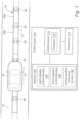
- an electric road system is illustrated.
- the electric road system is arranged in connection with a road 10.
- a vehicle 20, here in the form of an electric car is driving on the road 10.
- a longitudinal direction LV of the vehicle 20 is shown in Fig. 1 .
- the general function of the electric road system is that it provides electrical power to the vehicle 20 driving along the road 10.
- an electric motor of the vehicle 20 can be provided with electric power from the electric road system while the vehicle 20 is driving on the road 10.
- a battery of the vehicle 20 can be charged while the vehicle 20 is driving on the road 10.
- the electric road system may comprise a track 30, as shown in Fig. 1 .
- the track 30 is arranged to provide electrical power to the vehicle 20.
- a longitudinal direction LT of the track line 30 is shown in Fig. 1 .
- the longitudinal direction LV of the vehicle 20 is aligned with the longitudinal direction LT of the track line 30. In other words, they are parallel with respect to one another.
- the track 30 may be arranged on the surface of the road 10.
- the track 30 may protrude from the surface of the road 10.
- the track 30 may be arranged within a road surface of the road 10.
- the track 30 may be in level with the road surface of the road 10.
- the track 30 is segmented into two different types of track segments 30a, 30b.
- a length of each track segment may be in a range from 25cm to 200cm, preferably 30-150cm.
- a width of each segment may be in a range from 4cm to 40cm.
- the track segments 30a, 30b may be separated along the track 30 by electrically isolating members (not shown in Fig. 1 ).
- a first type of track segments 30a may be individually activated/deactivated to carry an electrical potential in its active state.
- a second type of track segments 30b may be track segments electrically connected to ground. Every second track segment of the track line 30 may be a track segment of the first type 30a. Every second track segment of the track line 30 may be a track segment of the second type 30b.
- the track line 30 further comprises a plurality of light indicators 40 arranged along the track line 30.
- Each track segment 30a, 30b of the track line 30 may comprise a light indicator 40.
- the track segments of the first type 30a may comprise a light indicator 40.
- Each light indicator 40 may comprise two or more individual light sources.
- Each light source may comprise one or more LEDs.
- the light sources may emit green light, red light, or any other color light.
- a color of the light indicator 40 may vary based on if the track segment of the first type 30a associated with the light indicator 40 is in an activated or deactivated state. For instance, a light indicator 40 may emit a green light upon the track segment 30a associated with the light indicator 40 is in the active state.
- the light indicator 40 is said to be in an active state when it is set to emit light in response to that a track segment of the first type 30a associated with the light indicator 40 is in an activate state.
- a light indicator 40 may emit a red light upon the track segment of the first type 30a associated with light indicator 40 is in the deactivated state.
- a light indicator 40 may be off, i.e. emitting no light, upon the track segment of the first type 30a associated with light indicator 40 is in the deactivated state.
- the light indicator 40 is said to be in a deactivate state when it is set to emit light or set to be off in response to that a track segment of the first type 30a associated with the light indicator 40 is in a deactivate state.
- the light indicators 40 may be arranged with an interval of 1 meter along the track line 30.
- the electric road system may further comprise control server 110.
- the control server 110 comprises a transceiver 112, a server control circuit 114 and a memory 116.
- the transceiver 112 is configured to communicate with the vehicle 20.
- the communication with the vehicle is typically made wirelessly. Suitable protocols for wireless communication, both long range and short range are well known to the skilled person and will not be discussed in any detail.
- the transceiver 112 is further configured to individually communicate with the plurality of light indicators 40. This in order to send activation/deactivation signals to the respective light indicator 40. The communication may be made wirelessly or wired.
- the transceiver 112 is further configured to individually communicate with the track segments of the first type 30a. This in order to send activation/deactivation signals to the respective track segment of the first type 30a. The communication may be made wirelessly or wired.
- the control circuit 114 is configured to carry out overall control of functions and operations of the control server 110.
- the server control circuit 114 may include a processor 118, such as a central processing unit (CPU), microcontroller, or microprocessor.
- the processor 118 is configured to execute program code stored in the memory 116, in order to carry out functions and operations of the control server 110.
- the memory 116 may be one or more of a buffer, a flash memory, a hard drive, a removable media, a volatile memory, a non-volatile memory, a random access memory (RAM), or another suitable device.
- the memory 116 may include a non-volatile memory for long term data storage and a volatile memory that functions as system memory for the control circuit 116.
- the memory 116 may exchange data with the server control circuit 114 over a data bus. Accompanying control lines and an address bus between the memory 116 and the server control circuit 114 also may be present.
- Functions and operations of the control server 110 may be embodied in the form of executable logic routines (e.g., lines of code, software programs, etc.) that are stored on a non-transitory computer readable medium (e.g., the memory 116) of the control server 110 and are executed by the server control circuit 114 (e.g., using the processor 118).
- the functions and operations of the control server 110 may be a stand-alone software application or form a part of a software application that carries out additional tasks related to the control server 110.
- the described functions and operations may be considered a method that the corresponding device is configured to carry out.
- the described functions and operations may be implemented in software, such functionality may as well be carried out via dedicated hardware or firmware, or some combination of hardware, firmware and/or software.
- the server control circuit 114 may execute a light indicator control function 120.
- the light indicator control function 120 is configured to individually activate/deactivate each of the plurality of light indicators 40.
- the server control circuit 114 may further execute a track segment control function 130.
- the track segment control function 130 is configured to activate/deactivate the track segments of the first type 30a.
- the light indicator control function 120 and the track segment control function 130 may be set to be synchronized. That is, upon the track segment control function 130 activates a track segment of the first type 30a, the light indicator control function 120 may be set to active one or more light indicators 40 associated with the activated track segment of the first type 30a.
- the server control circuit 114 may execute a vehicle position determining function 140.
- the vehicle position determining function 140 is configured to determine a position of the vehicle 20.
- the track segment control function 130 may be configured to, based on the position of the vehicle 20, determined by the vehicle position determining function 140, determine whether the vehicle 20 is approaching a portion of the track line 30 comprising a specific track segment of the first type 30a. Upon the vehicle 20 is approaching the portion of the track line 30 comprising the specific track segment of the first type 30a, the track segment control function 130 may be configured to activate the specific track segment of the first type 30a.
- the light indicator control function 120 may be configured to, based on the position of the vehicle 20, determined by the vehicle position determining function 140, determine whether the vehicle 20 is approaching a portion of the track line 30 comprising a specific track segment of the first type 30a. Alternatively, or in combination, the light indicator control function 120 may be configured to determine whether the vehicle 20 is approaching the portion of the track line 30 comprising the specific track segment of the first type 30a from information provided by the track segment control function 130. Upon the vehicle 20 is approaching the portion of the track line 30 comprising the specific track segment of the first type 30a, the light indicator control function 120 may be configured to activate the light indicators 40, among the plurality of light indicators 40, being associated with the specific track segment of the first type 30a.
- the track segment control function 130 may be configured to, based on the position of the vehicle 20, determined by the vehicle position determining function 140, determine whether the vehicle 20 is leaving a portion of the track line 30 comprising a specific track segment of the first type 30a. Upon the vehicle 20 is leaving the portion of the track line 30 comprising the specific track segment of the first type 30a, the track segment control function 130 may be configured to deactivate the specific track segment of the first type 30a.
- the light indicator control function 120 may be configured to, based on the position of the vehicle 20, determined by the vehicle position determining function 140, determine whether the vehicle 20 is leaving a portion of the track line 30 comprising a specific track segment of the first type 30a. Alternatively, or in combination, the light indicator control function 120 may be configured to determine whether the vehicle 20 is leaving the portion of the track line 30 comprising the specific track segment of the first type 30a from information provided by the track segment control function 130. Upon the vehicle 20 is leaving the portion of the track line 30 comprising the specific track segment of the first type 30a, the light indicator control function 120 may be configured to deactivate the light indicators 40, among the plurality of light indicators 40, being associated with the specific track segment of the first type 30a.
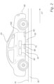
- FIG. 2 a side view of an electric vehicle 20 driving on the electric road system of Fig. 1 is shown.
- the electric vehicle 20 comprises a sliding contact 50.
- the sliding contact 50 is part of an electrical power collector 70 mounted on the vehicle 20.
- the electrical power collector 70 is configured to collect electrical power from the track line 30 of the electric road system.
- the electrical power collector 70 typically comprise two or more sliding contacts 50.
- the sliding contacts 50 may be arranged under the vehicle 20.
- the sliding contact 50 may move laterally with respect to the longitudinal direction LV of the vehicle 20.
- the two or more sliding contacts 50 may be arranged along the longitudinal direction of the vehicle LV.
- a distance between the two contacts of the sliding contact may be in a range from 30cm to 150cm.
- Each of the two or more sliding contacts 50 is configured to make sliding contact with a different one of the track segments 30a, 30b of the track line 30 while the electric vehicle is driving along the track line 30.
- at least one sliding contact 50 is configured to make sliding contact with a track segment of the first type 30a and at least one sliding contact 50 is configured to make sliding contact with a track segment of the second type 30b while the electric vehicle is driving along the track line 30.
- the electrical power collector 70 will be able to provide the vehicle 20 with electric power from the track line 30.
- a size of each contact of the sliding contact 50, along a lateral direction of the vehicle 20, may be in a range from 3cm to 10cm.
- the electrical power collector 70 may be connected to a battery of the vehicle 20.
- the electrical power collector 70 may be connected to an electric motor of the vehicle 20.
- the electrical power collector 70 may supply electrical power for driving the vehicle 20.
- the electrical power collector 70 may be mounted anywhere in the vehicle 20.
- the electrical power collector 70 may be mounted under the vehicle 20
- the vehicle 20 further comprises a control circuit 100 configured to control the electrical power collector 70, i.e. activate/deactive the same.
- the control circuit 100 may further be configured to guide a sliding contact 50 of the electrical power collector 70 such that it makes sliding contact with the track line 30 of the electric road system while the vehicle 20 is driving along the track line 30.
- the control circuit 100 comprises a camera 60 and processor 80.
- the camera 60 is configured to capture a video stream. Especially, the camera 60 is configured to capture a video stream depicting the track line 30 while the vehicle is driving along the track line 30. This may be achieved by mounting the camera 60 on vehicle 20 such that the camera 60 is able to capture the video stream depicting the track line 30 while the vehicle is driving along the track line 30.
- the camera 60 may be mounted under the vehicle 20. Alternatively, or in combination, the camera may be mounted on a front portion of the vehicle 20, e.g., in the front of the vehicle close to a front bumper or behind an upper portion of the windscreen. There may be more than one camera 60 mounted on the vehicle 20.
- the processor 80 may be a central processing unit (CPU), a microcontroller or a microprocessor.
- the processor 80 is configured to execute program code stored in a memory of the control circuit 100, in order to carry out operations and functions of the control circuit 100.
- the operations and functions of the control circuit 100 may be embodied in the form of executable logic routines, e.g., lines of code, software programs etc., that are stored on the memory and are executed by the processor 80.
- the operations and functions of the control circuit 100 may be a stand-alone software application or form a part of a software application that carries out additional tasks related to the control circuit 100.
- the described operations and functions may be considered a method that the control circuit 100 is configured to carry out.
- the described operations and functions will be discussed as implemented in software, such functionality may as well be carried out via dedicated hardware or firmware, or some combination of hardware, firmware and/or software.
- the processor 80 is configured to execute a light indicator finding function.
- the light indicator finding function is configured to analyze the video stream captured by the camera 60. Especially, the light indicator finding function is configured to analyze the video stream depicting the track line 30 while the vehicle 20 is driving along the track line 30.
- the light indicator finding function may be configured to identify positions of active light indicators 40 arranged on the track line 30 within images of the video stream.
- the processor may further be configured to execute a sliding contact guiding function.
- the sliding contact guiding function is configured to generate a guiding signal based on the identified positions of the active light indicators 40 as identified by the light indicator finding function.
- the control circuit 100 may further comprise an actuator 90 configured to move the sliding contact 50 laterally with respect to a longitudinal direction of the vehicle based on the guiding signal, thereby guiding the sliding contact 50.
- the processor 80 may further be configured to execute a vehicle steering function.
- the vehicle steering function is configured to steer the vehicle 20 laterally with respect to a longitudinal direction of the track line 30 based on the guiding signal, thereby guiding the sliding contact 50.
- the light indicator finding function may further be configured to identify active light indicators 40 in the video stream captured by the camera. Upon identification of active light indicators 40 in the video stream, the light indicator finding function may generate an electrical power collector activation signal.
- the electrical power collector activation signal may be sent to the electrical power collector 70.
- the electrical power collector activation signal may activate the electrical power collector 70.
- the activation of the electrical power collector 70 may activate the sliding contact 50 such that the sliding contact 50 may make a sliding contact with the track line 30.
- the sliding contact 50 may be moved downwards i.e. towards the road surface to make the sliding contact with the track line 30.
- the light indicator finding function may further be configured to identify no active light indicators 40 in the video stream captured by the camera. Upon identification of no active light indicators 40 in the video stream, the light indicator finding function may generate an electrical power collector deactivation signal.
- the electrical power collector deactivation signal may be sent to the electrical power collector 70.
- the electrical power collector deactivation signal may deactivate the electrical power collector 70.
- the deactivation of the electrical power collector 70 may deactivate the sliding contact 50.
- the deactivated sliding contact 50 may be prevented from making a sliding contact with the track line 30.
- the sliding contact 50 may be lifted toward the vehicle i.e. away from the surface of the road to make no sliding contact with the track line 30.
- the electrical power collector activation/deactivation signal may be generated based on defined criteria. For instance, the electrical power collector deactivation signal may be generated upon not identifying active light indicators 40 within a predefined time.
- the predefined time may e.g. be in the range of 0.5 to 3 seconds. By setting this predefined time sufficiently short, wear on the sliding contact 50 may be reduced.
- the processor 80 may further be configured to execute a vehicle movement detection function.
- the vehicle movement detection function is configured to monitor a lateral movement of the vehicle 20.
- the vehicle movement detection function is further configured to, upon lateral movement of the vehicle 20 is above a predetermined threshold, generate an electrical power collector deactivation signal.
- a typical lateral movement of a vehicle 20 may be 0.3 m/s.
- the predetermined threshold may hence be set to be 0.5 m/s.
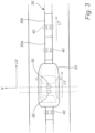
- Fig. 3 shows positions of contacts of the sliding contact 50 with respect to the track line 30.
- the dashed lines of Fig .3 indicate the lateral positions, positions along X direction, of the contacts of the sliding contacts 50.
- the guiding of the sliding contacts 50 may comprise moving the sliding contact 50 laterally, along X direction, with respect to the longitudinal direction LT of the track line 30.
- the moving of the sliding contact 50 along X direction may be performed such that the contacts of the sliding contact 50 make a sliding contact with the track line 30.
- the sliding contacts 50 may be guided laterally with respect to the longitudinal direction LT of the track line 30 by the actuator 90 of the control circuit 100.
- the actuator is set to be moving the sliding contacts 50 laterally with respect to a longitudinal direction LV of the vehicle 20, and hence also laterally with respect to the longitudinal direction LT of the track line 30, based on the guiding signal generated by the sliding contact guiding function.
- the sliding contacts 50 may be guided laterally with respect to the longitudinal direction LT of the track line 30 by steering the vehicle 20 laterally with respect to the longitudinal direction LT of the track line 30.
- the guiding of the sliding contacts 50 are performed such that the sliding contact 50 make a sliding contact only with the track line 30.
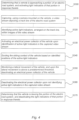
- a block scheme of a method for controlling an electric road system and/or a vehicle 20 to collect electrical power from the electric road system is illustrated.
- the steps of the method may be performed in any order suitable.
- the method may comprises one or more of the following steps.
- the steps are preferably to be performed while the vehicle 20 is driving.
- the activation of the light indicators 40 of that portion may be performed by a light indicator controller 120, as described above.
- Identifying S320 active light indicators 40 arranged on the track line, within images of the captured video stream.
- the act of identifying S320 may comprise identifying positions of the active light indicators 40.
- the step of guiding S340 the sliding contact 50 may comprise moving the sliding contact 50 laterally with respect to a longitudinal direction LV of the vehicle 20.
- the step of guiding the sliding contact 50 of the vehicle 20 may comprise steering the vehicle 20 laterally with respect to a longitudinal direction LT of the track line 30.
- the deactivation of the light indicators 40 of that portion may be performed by the light indicator controller 120, as described above.
- the track 30 may be arranged along a wall of a tunnel, e.g. a mine tunnel.
- the track 30 may then form part of a side railing.
- the light indicator 40 may be configured to emit IR light.
- the light indicator 40 may be configured to emit IR light in the active state. If so the camera 60 is configured to capture IR light.
- the light indicators 40 may be configured to emit pulsating light.
- the frequency of the pulsation may be in the range of 10-100Hz. By pulsating the light, the emitted light may be easier to distinguish in e.g. strong sunlight.
- a simpler track not being able to provide a vehicle with power but comprising the light indicators 40 may be used for steering a vehicle for lane keeping purpose, the vehicle being equipped with the camera 60.
- the track 30 discussed above may be used for steering a vehicle for lane keeping purpose, the vehicle being equipped with the camera 60.
Landscapes
- Engineering & Computer Science (AREA)
- Mechanical Engineering (AREA)
- Power Engineering (AREA)
- Transportation (AREA)
- Physics & Mathematics (AREA)
- General Physics & Mathematics (AREA)
- Automation & Control Theory (AREA)
- Aviation & Aerospace Engineering (AREA)
- Radar, Positioning & Navigation (AREA)
- Remote Sensing (AREA)
- Theoretical Computer Science (AREA)
- Electromagnetism (AREA)
- Computer Vision & Pattern Recognition (AREA)
- Multimedia (AREA)
- Life Sciences & Earth Sciences (AREA)
- Sustainable Development (AREA)
- Sustainable Energy (AREA)
- Current-Collector Devices For Electrically Propelled Vehicles (AREA)
- Electric Propulsion And Braking For Vehicles (AREA)
- Lighting Device Outwards From Vehicle And Optical Signal (AREA)
- Charge And Discharge Circuits For Batteries Or The Like (AREA)
Abstract
Description
- The present inventive concept relates to a method for controlling an electrical power collector of a vehicle, driving on an electric road system arranged along a road, to collect electrical power from a track line of the electric road system. A control circuit and a control system configured so that the controlling can be performed are also presented.
- Over the past years, electric vehicles such as electric cars have developed rapidly. Most current electric vehicles are powered by lithium-ion batteries. The lithium-ion batteries are more stable and offer a higher charging capacity, compared to the conventional batteries such as lead or nickel batteries.
- However, the use of electric vehicles is limited by capacity of batteries and also by electric vehicle charging infrastructure. In addition, considering the growing demand of electric vehicles, the demand for electric vehicle charging infrastructure would be even higher in the coming years.
- An objective of the present inventive concept is to address this need. Further and alternative objectives may be understood from the following.
- According to a first aspect a method is provided for controlling an electrical power collector. The electrical power collector is configured to, via a sliding contact, collect electrical power from a track line of an electric road system arranged along a road. The track line comprising activatable light indicators arranged on the track line. The electrical power collector is mounted on a vehicle. The method comprises, while the vehicle is driving, capturing, using a camera mounted on the vehicle, a video stream depicting the track line, identifying active light indicators in the captured video stream, and upon identification of active light indicators, activating the electrical power collector such that the sliding contact makes sliding contact with the track line.
- The capturing of the video stream by the camera to identify active light indicators provides a convenient and efficient way of activating the electrical power collector. Further, wear on the sliding contact may be reduced. This since activation of the electrical power collector may be controlled based on a state of the track line, the light indicators indicating an active track line or not.
- By an electric road system is hereby meant an electric system arranged along a road configured to provide electrical power to e.g. vehicles driving on that road.
- By a vehicle is hereby meant an electric vehicle which is driven by an electric motor. For instance, the electric vehicle may be an electric car, an electric truck or an electric buss. The electric vehicle may comprise one or more chargeable batteries providing electrical power to the electric motor.
- By a track line is hereby meant a line arranged along a road. The track line may form a part of the electronic road system. The track line may be arranged on a surface of a road. The track line may be arranged within a road surface of the road. The track line may be arranged along a central portion of a lane of the road.
- By an electrical power collector is hereby meant an electrical component configured to collect electrical power. The electrical power collector may be mounted on the electric vehicle. The electrical power collector may provide electrical power for driving the electric motor of the electric vehicle. The electrical power collector may provide electrical power for charging batteries of the electric vehicle.
- By a sliding contact is hereby meant a contact collecting electrical power form the track line. The sliding contact may be set in sliding contact with the track line in order to collect electrical power form the track line while the electric vehicle is driving along the track line.
- The method may further comprise identifying positions of active light indicators, arranged on the track line, within images of the video stream, and laterally, with respect to a longitudinal direction of the track line, guiding the sliding contact based on the identified positions of the active light indicators. The capturing of the video stream by the camera to identify the positions of the active light indicators provides an input about the position of the vehicle with respect to the track line of the electric road system. The obtained input allows guiding the sliding contact of the vehicle with respect to the track line and hence allows collecting electrical power from the track line. Thereby, the vehicle collects electrical power from the track line of the electric road system while the vehicle is driving. This in turn reduces the demand of electric vehicle charging stations e.g. at parking stations and also allows driving the vehicle for a longer time than charged batteries provide the electrical power. Further, by guiding the sliding contact of the vehicle with respect to the track line, the track line may be integrated in a road surface of the road. Especially, a contact surface of the track line making contact with the sliding contact of the vehicle may be in level with the road surface.
- The step of guiding the sliding contact may comprise moving the sliding contact laterally with respect to a longitudinal direction of the electric vehicle. Thereby, the position of the sliding contact with respect to the track line may be adjusted allowing the sliding contact to collect electrical power from the track line while the electric vehicle is driving along the track line. The sliding contact may have a width, a dimension in the lateral direction of the electric vehicle, corresponding to a width of the track line, i.e. a dimension in the lateral direction of the track line.
- By a longitudinal direction of a vehicle is hereby meant a driving direction of the vehicle. By a lateral direction of a vehicle is hereby meant a direction perpendicular to the longitudinal direction of the vehicle. By a longitudinal direction of the track line is hereby meant a direction along the track line. By a lateral direction of a track line is hereby meant a direction perpendicular to the longitudinal direction of the track line.
- The step of guiding the sliding contact may comprise steering the electrical vehicle laterally with respect to a longitudinal direction of the track line. Thereby, adjusting the position of the sliding contact with respect to the track line may be adjusted to allow collecting electrical power from the track line while the electric vehicle is driving along the track line. By steering the electrical vehicle, the complexity of the sliding contact may be reduced. For example, the sliding contact itself may not need to be moveable in the lateral direction of the electric vehicle.
- The method may further comprise determining that the vehicle is approaching a portion of the electric road system, and activating the light indicators of that portion in response thereto. Thereby, the light indicators may not need to be active all the time. Hence, energy may be saved.
- The method may further comprise determining that the vehicle is leaving the portion of the electric road system, and deactivating the light indicators of that portion in response thereto. The deactivation of the light indicators when the vehicle leaves the portion of the electric road system may reduce electrical power consumption of the light indictors.
- The method may further comprise monitoring a lateral movement of the vehicle, and upon the lateral movement is above a predetermined threshold, deactivating the electrical power collector such that the sliding contact is prevented from making sliding contact with a surface of the road. With that the sliding contact is making sliding contact with something is meant that the sliding contact is making physical contact with this something while the vehicle is moving. Hence, the electrical power collector may be deactivated when the vehicle is steered away from the track line, e.g. in connection with a lane change or a departure from the road comprising the electric road system. The deactivation of the electrical power collector by preventing the sliding contact from making sliding contact with the surface of the road may be performed by lifting and/or tilting the sliding contact towards the electric vehicle, i.e. away from the surface of the road. By preventing the sliding contact to make sliding contact with the surface of the road may prevent the sliding contact from undesired wear and thereby increase a life span of the sliding contact.
- By a predetermined threshold is hereby meant a predetermined value of the lateral movement. The predetermined threshold value may be set by a driver based on preferences of the driver. The predetermined threshold value may be a factory set value. The predetermined threshold value may be updated via over the air updates of the electrical vehicle.
- The method may further comprise, upon not identifying active light indicators in the captured video stream, deactivating the electrical power collector such that the sliding contact makes no sliding contact with the track line or a surface of the road. Hence, a convenient and efficient way of deactivating the electrical power collector is provided. Further, the life span of the sliding contact may be enhanced. This since wear from e.g. the sliding contact make sliding contact with the surface of road may be prevented.
- According to a second aspect a control circuit for controlling an electrical power collector configured to collect electrical power from a track line of an electric road system arranged along a road is provided. The track line comprising activatable light indicators arranged on the track line. The electrical power collector and the control circuit being mounted on a vehicle. The control circuit comprises: a camera configured to capture a video stream depicting the track line; and a processor configured to execute: a light indicator finding function configured to identify active light indicators within images of the video stream and, upon identification of active light indicators, generate an electrical power collector activation signal.
- By identifying active light indicators, a convenient and efficient way of activating the electrical power collector is provided. Further, wear on a sliding contact of the electrical power collector may be reduced. This since activation of the electrical power collector may be controlled based on a state of the track line, the light indicators indicating an active track line or not.
- The control circuit together with the electrical power collector may be as a package to be installed on vehicles allowing them to collect electrical power from the track line of the electric road system.
- The light indicator finding function may further identify positions of active light indicators, arranged on the track line, within images of the video stream. The processor may further be configured to execute a sliding contact guiding function configured to generate a guiding signal based on the identified positions of the active light indicators. Thereby the control circuit may guide a sliding contact of the electrical power collector, while the vehicle is driving, to collect electrical power from the track line of the electric road system arranged along the road.
- The above-mentioned features of the method according to the first aspect, when applicable, apply to this second aspect as well. In order to avoid undue repetition, reference is made to the above.
- The control circuit may further comprise an actuator configured to move the sliding contact laterally with respect to the longitudinal direction of the vehicle, based on the guiding signal, thereby guiding the sliding contact. Thereby the actuator may move the sliding contact based on the guiding signal. This may in turn allow the sliding contact to collect electrical power from the track line of the electric road system arranged along the road while the vehicle is driving along the track line.
- The processor may further be configured to execute a vehicle steering function configured to steer the vehicle laterally with respect to a longitudinal direction of the track line based on the guiding signal, thereby guiding the sliding contact. Thereby, allowing the sliding contact to collect electrical power from the track line of the electric road system arranged along the road while the vehicle is driving along the track line.
- The processor may further be configured to execute a vehicle movement detection function configured to: monitor a lateral movement of the vehicle, and upon the lateral movement is above a predetermined threshold, generate an electrical power collector deactivation signal. Thereby, a deactivation signal may be generated when the vehicle is steered to change lane or departure from the road comprising the electric road system. The deactivation signal may prevent the sliding contact from making a sliding contact with the surface of the road and thereby reducing wear on the sliding contact. The preventing the sliding contact from making sliding contact with the surface of the road may be performed by e.g. lifting or tilting the sliding contact towards the vehicle i.e. away from the surface of the road.
- The light indicator finding function may further be configured to identify no active light indicators within images of the video stream, and upon identification of no active light indicators, generate an electrical power collector deactivation signal. The generation of the electrical power collector activation or deactivation signal may respectively activate or deactivate the electrical power collector. This in turn may increase a life span of the sliding contact.
- According to a third aspect a control system for controlling an electrical power collector configured to collect electrical power from a track line of an electric road system arranged along a road is provided. The electrical power collector is mounted on a vehicle. The control system comprises a plurality of activatable light indicators arranged along the track line, and a control circuit according to the second aspect.
- The plurality of the light indicators and the control circuit allow controlling of the electrical power collector, such as activation/deactivation of the same. The plurality of the light indicators and the control circuit further allow guiding of a sliding contact of the electrical power collector of the vehicle driving along the road comprising the electric road system to collect electrical power from the track line of the electric road system. The above-mentioned features of the method according to the first aspect or the control circuit according to the second aspect, when applicable, apply to this third aspect as well. In order to avoid undue repetition, reference is made to the above.
- The control system may further comprise a control server comprising a server control circuit configured to execute a light indicator control function configured to individually activate/deactivate each of the plurality of light indicators. The individual activation/deactivation of each of the plurality of light indicators may facilitate identification of the positions of the active light indicators by the camera. It may also reduce electrical power consumption of the light indictors i.e. at least reduced electrical power consumption when the light indicators are deactivated.
- The server control circuit may further be configured to execute a vehicle position determining function configured to determine a position of the vehicle. The light indicator control function may be configured to, based on the position of the vehicle, determine whether the vehicle is approaching a portion of the track line comprising a specific track segment. The light indicator control function may further be configured to activate light indicators of the portion of the track line approached by the vehicle. The light indicator control function may further be configured to, based on the position of the vehicle, determine whether the vehicle is leaving a portion of the track line comprising a specific track segment. The light indicator control function may further be configured to deactivate the light indicators of the portion of the track line left by the vehicle. Thereby the respective activation or deactivation of the light indicators of the portion of the electric road system approached or left by the vehicle may be performed based on an input form the vehicle position determining device of the control system. The vehicle position determining device may be connected to the internet e.g. over a 4G network. The vehicle position determining device may be connected to a global positioning system (GPS) to determine the position of the vehicle. The vehicle position determining device may be connected to a network of traffic cameras to determine the position of the vehicle.
- The light indicators, in active state, may be configured to emit green light. The light indicator, in deactive state, may be configured to emit red light. The light indicators may be configured to emit another light in active or deactive state. According to experiments performed by the inventors, the use of the green light for the active state facilitates the detection of the positions of active light indicators by the camera.
- Each of the plurality of light indicator may comprise two or more individual light sources. Hence, the redundancy of the light indicators may be enhanced. This since if one of the light sources of a light indicator stops working the light indicator may still be functional in providing guidance for the sliding contact. Safety and reliability of the control system may hence be enhanced. The light source(s) of the light indicators may be based on LEDs. Durable and low power light sources are thereby provided.
- A further scope of applicability of the present invention will become apparent from the detailed description given below. However, it should be understood that the detailed description and specific examples, while indicating preferred embodiments of the invention, are given by way of illustration only, since various changes and modifications within the scope of the invention will become apparent to those skilled in the art from this detailed description.
- Hence, it is to be understood that this invention is not limited to the particular component parts of the device described or steps of the methods described as such device and method may vary. It is also to be understood that the terminology used herein is for purpose of describing particular embodiments only, and is not intended to be limiting. It must be noted that, as used in the specification and the appended claim, the articles "a," "an," "the," and "said" are intended to mean that there are one or more of the elements unless the context clearly dictates otherwise. Thus, for example, reference to "a camera" or "the camera" may include several devices, and the like. Furthermore, the words "comprising", "including", "containing" and similar wordings does not exclude other elements or steps.
- The above and other aspects of the present invention will now be described in more detail, with reference to appended drawings showing embodiments of the invention. The figures should not be considered limiting the invention to the specific embodiment; instead they are used for explaining and understanding the invention.
- As illustrated in the figures, the sizes are exaggerated for illustrative purposes and, thus, are provided to illustrate the general structures of embodiments of the present invention. Like reference numerals refer to like elements throughout.
-
Fig. 1 is a top view of an electric road system arranged on a road. -
Fig. 2 is a side view of a vehicle driving on the electric road system ofFig. 1 . -
Fig. 3 is a top view of the vehicle driving on the electric road system ofFig. 1 . -
Fig. 4 is a block scheme of a method for guiding a sliding contact of an electrical power collector configured to collect electrical power from a track line of an electric road system of e.g.Fig. 1 . - The present invention will now be described more fully hereinafter with reference to the accompanying drawings, in which currently preferred embodiments of the invention are shown. This invention may, however, be embodied in many different forms and should not be construed as limited to the embodiments set forth herein; rather, these embodiments are provided for thoroughness and completeness, and to fully convey the scope of the invention to the skilled person.
- In connection with
Fig.1 , an electric road system is illustrated. The electric road system is arranged in connection with aroad 10. InFig. 1 avehicle 20, here in the form of an electric car, is driving on theroad 10. A longitudinal direction LV of the vehicle 20is shown inFig. 1 . The general function of the electric road system is that it provides electrical power to thevehicle 20 driving along theroad 10. Thus, an electric motor of thevehicle 20 can be provided with electric power from the electric road system while thevehicle 20 is driving on theroad 10. Alternatively, or in combination, a battery of thevehicle 20 can be charged while thevehicle 20 is driving on theroad 10. - The electric road system may comprise a
track 30, as shown inFig. 1 . Thetrack 30 is arranged to provide electrical power to thevehicle 20. A longitudinal direction LT of the track line 30is shown inFig. 1 . As shown inFig. 1 , the longitudinal direction LV of the vehicle 20is aligned with the longitudinal direction LT of thetrack line 30. In other words, they are parallel with respect to one another. Thetrack 30 may be arranged on the surface of theroad 10. Thetrack 30 may protrude from the surface of theroad 10. Thetrack 30 may be arranged within a road surface of theroad 10. Thetrack 30 may be in level with the road surface of theroad 10. - The
track 30 is segmented into two different types oftrack segments track segments track 30 by electrically isolating members (not shown inFig. 1 ). A first type oftrack segments 30a may be individually activated/deactivated to carry an electrical potential in its active state. A second type oftrack segments 30b may be track segments electrically connected to ground. Every second track segment of thetrack line 30 may be a track segment of thefirst type 30a. Every second track segment of thetrack line 30 may be a track segment of thesecond type 30b. - The
track line 30 further comprises a plurality oflight indicators 40 arranged along thetrack line 30. Eachtrack segment track line 30 may comprise alight indicator 40. Alternatively, the track segments of thefirst type 30a may comprise alight indicator 40. Eachlight indicator 40 may comprise two or more individual light sources. Each light source may comprise one or more LEDs. The light sources may emit green light, red light, or any other color light. A color of thelight indicator 40 may vary based on if the track segment of thefirst type 30a associated with thelight indicator 40 is in an activated or deactivated state. For instance, alight indicator 40 may emit a green light upon thetrack segment 30a associated with thelight indicator 40 is in the active state. Thelight indicator 40 is said to be in an active state when it is set to emit light in response to that a track segment of thefirst type 30a associated with thelight indicator 40 is in an activate state. Alight indicator 40 may emit a red light upon the track segment of thefirst type 30a associated withlight indicator 40 is in the deactivated state. Alternatively, alight indicator 40 may be off, i.e. emitting no light, upon the track segment of thefirst type 30a associated withlight indicator 40 is in the deactivated state. Thelight indicator 40 is said to be in a deactivate state when it is set to emit light or set to be off in response to that a track segment of thefirst type 30a associated with thelight indicator 40 is in a deactivate state. Thelight indicators 40 may be arranged with an interval of 1 meter along thetrack line 30. - The electric road system may further comprise
control server 110. Thecontrol server 110 comprises atransceiver 112, aserver control circuit 114 and amemory 116. - The
transceiver 112 is configured to communicate with thevehicle 20. The communication with the vehicle is typically made wirelessly. Suitable protocols for wireless communication, both long range and short range are well known to the skilled person and will not be discussed in any detail. Thetransceiver 112 is further configured to individually communicate with the plurality oflight indicators 40. This in order to send activation/deactivation signals to the respectivelight indicator 40. The communication may be made wirelessly or wired. Thetransceiver 112 is further configured to individually communicate with the track segments of thefirst type 30a. This in order to send activation/deactivation signals to the respective track segment of thefirst type 30a. The communication may be made wirelessly or wired. - The
control circuit 114 is configured to carry out overall control of functions and operations of thecontrol server 110. Theserver control circuit 114 may include aprocessor 118, such as a central processing unit (CPU), microcontroller, or microprocessor. Theprocessor 118 is configured to execute program code stored in thememory 116, in order to carry out functions and operations of thecontrol server 110. - The
memory 116 may be one or more of a buffer, a flash memory, a hard drive, a removable media, a volatile memory, a non-volatile memory, a random access memory (RAM), or another suitable device. In a typical arrangement, thememory 116 may include a non-volatile memory for long term data storage and a volatile memory that functions as system memory for thecontrol circuit 116. Thememory 116 may exchange data with theserver control circuit 114 over a data bus. Accompanying control lines and an address bus between thememory 116 and theserver control circuit 114 also may be present. - Functions and operations of the
control server 110 may be embodied in the form of executable logic routines (e.g., lines of code, software programs, etc.) that are stored on a non-transitory computer readable medium (e.g., the memory 116) of thecontrol server 110 and are executed by the server control circuit 114 (e.g., using the processor 118). Furthermore, the functions and operations of thecontrol server 110 may be a stand-alone software application or form a part of a software application that carries out additional tasks related to thecontrol server 110. The described functions and operations may be considered a method that the corresponding device is configured to carry out. Also, while the described functions and operations may be implemented in software, such functionality may as well be carried out via dedicated hardware or firmware, or some combination of hardware, firmware and/or software. - The
server control circuit 114 may execute a light indicator control function 120. The light indicator control function 120 is configured to individually activate/deactivate each of the plurality oflight indicators 40. Theserver control circuit 114 may further execute a tracksegment control function 130. The tracksegment control function 130 is configured to activate/deactivate the track segments of thefirst type 30a. The light indicator control function 120 and the tracksegment control function 130 may be set to be synchronized. That is, upon the tracksegment control function 130 activates a track segment of thefirst type 30a, the light indicator control function 120 may be set to active one or morelight indicators 40 associated with the activated track segment of thefirst type 30a. - The
server control circuit 114 may execute a vehicleposition determining function 140. The vehicleposition determining function 140 is configured to determine a position of thevehicle 20. - The track
segment control function 130 may be configured to, based on the position of thevehicle 20, determined by the vehicleposition determining function 140, determine whether thevehicle 20 is approaching a portion of thetrack line 30 comprising a specific track segment of thefirst type 30a. Upon thevehicle 20 is approaching the portion of thetrack line 30 comprising the specific track segment of thefirst type 30a, the tracksegment control function 130 may be configured to activate the specific track segment of thefirst type 30a. - The light indicator control function 120 may be configured to, based on the position of the
vehicle 20, determined by the vehicleposition determining function 140, determine whether thevehicle 20 is approaching a portion of thetrack line 30 comprising a specific track segment of thefirst type 30a. Alternatively, or in combination, the light indicator control function 120 may be configured to determine whether thevehicle 20 is approaching the portion of thetrack line 30 comprising the specific track segment of thefirst type 30a from information provided by the tracksegment control function 130. Upon thevehicle 20 is approaching the portion of thetrack line 30 comprising the specific track segment of thefirst type 30a, the light indicator control function 120 may be configured to activate thelight indicators 40, among the plurality oflight indicators 40, being associated with the specific track segment of thefirst type 30a. - The track
segment control function 130 may be configured to, based on the position of thevehicle 20, determined by the vehicleposition determining function 140, determine whether thevehicle 20 is leaving a portion of thetrack line 30 comprising a specific track segment of thefirst type 30a. Upon thevehicle 20 is leaving the portion of thetrack line 30 comprising the specific track segment of thefirst type 30a, the tracksegment control function 130 may be configured to deactivate the specific track segment of thefirst type 30a. - The light indicator control function 120 may be configured to, based on the position of the
vehicle 20, determined by the vehicleposition determining function 140, determine whether thevehicle 20 is leaving a portion of thetrack line 30 comprising a specific track segment of thefirst type 30a. Alternatively, or in combination, the light indicator control function 120 may be configured to determine whether thevehicle 20 is leaving the portion of thetrack line 30 comprising the specific track segment of thefirst type 30a from information provided by the tracksegment control function 130. Upon thevehicle 20 is leaving the portion of thetrack line 30 comprising the specific track segment of thefirst type 30a, the light indicator control function 120 may be configured to deactivate thelight indicators 40, among the plurality oflight indicators 40, being associated with the specific track segment of thefirst type 30a. - In connection with
Fig. 2 , a side view of anelectric vehicle 20 driving on the electric road system ofFig. 1 is shown. Theelectric vehicle 20 comprises a slidingcontact 50. The slidingcontact 50 is part of anelectrical power collector 70 mounted on thevehicle 20. Theelectrical power collector 70 is configured to collect electrical power from thetrack line 30 of the electric road system. Theelectrical power collector 70 typically comprise two or more slidingcontacts 50. The slidingcontacts 50 may be arranged under thevehicle 20. The slidingcontact 50 may move laterally with respect to the longitudinal direction LV of thevehicle 20. The two or more slidingcontacts 50 may be arranged along the longitudinal direction of the vehicle LV. A distance between the two contacts of the sliding contact may be in a range from 30cm to 150cm. Each of the two or more slidingcontacts 50 is configured to make sliding contact with a different one of thetrack segments track line 30 while the electric vehicle is driving along thetrack line 30. At an instant of time, at least one slidingcontact 50 is configured to make sliding contact with a track segment of thefirst type 30a and at least one slidingcontact 50 is configured to make sliding contact with a track segment of thesecond type 30b while the electric vehicle is driving along thetrack line 30. Doing so theelectrical power collector 70 will be able to provide thevehicle 20 with electric power from thetrack line 30. A size of each contact of the slidingcontact 50, along a lateral direction of thevehicle 20, may be in a range from 3cm to 10cm. - The
electrical power collector 70 may be connected to a battery of thevehicle 20. Theelectrical power collector 70 may be connected to an electric motor of thevehicle 20. Theelectrical power collector 70 may supply electrical power for driving thevehicle 20. Theelectrical power collector 70 may be mounted anywhere in thevehicle 20. Theelectrical power collector 70 may be mounted under thevehicle 20 - The
vehicle 20 further comprises acontrol circuit 100 configured to control theelectrical power collector 70, i.e. activate/deactive the same. Thecontrol circuit 100 may further be configured to guide a slidingcontact 50 of theelectrical power collector 70 such that it makes sliding contact with thetrack line 30 of the electric road system while thevehicle 20 is driving along thetrack line 30. Thecontrol circuit 100 comprises acamera 60 andprocessor 80. - The
camera 60 is configured to capture a video stream. Especially, thecamera 60 is configured to capture a video stream depicting thetrack line 30 while the vehicle is driving along thetrack line 30. This may be achieved by mounting thecamera 60 onvehicle 20 such that thecamera 60 is able to capture the video stream depicting thetrack line 30 while the vehicle is driving along thetrack line 30. Thecamera 60 may be mounted under thevehicle 20. Alternatively, or in combination, the camera may be mounted on a front portion of thevehicle 20, e.g., in the front of the vehicle close to a front bumper or behind an upper portion of the windscreen. There may be more than onecamera 60 mounted on thevehicle 20. - The
processor 80 may be a central processing unit (CPU), a microcontroller or a microprocessor. Theprocessor 80 is configured to execute program code stored in a memory of thecontrol circuit 100, in order to carry out operations and functions of thecontrol circuit 100. The operations and functions of thecontrol circuit 100 may be embodied in the form of executable logic routines, e.g., lines of code, software programs etc., that are stored on the memory and are executed by theprocessor 80. Furthermore, the operations and functions of thecontrol circuit 100 may be a stand-alone software application or form a part of a software application that carries out additional tasks related to thecontrol circuit 100. The described operations and functions may be considered a method that thecontrol circuit 100 is configured to carry out. Also, while the described operations and functions will be discussed as implemented in software, such functionality may as well be carried out via dedicated hardware or firmware, or some combination of hardware, firmware and/or software. - The
processor 80 is configured to execute a light indicator finding function. The light indicator finding function is configured to analyze the video stream captured by thecamera 60. Especially, the light indicator finding function is configured to analyze the video stream depicting thetrack line 30 while thevehicle 20 is driving along thetrack line 30. The light indicator finding function may be configured to identify positions of activelight indicators 40 arranged on thetrack line 30 within images of the video stream. - The processor may further be configured to execute a sliding contact guiding function. The sliding contact guiding function is configured to generate a guiding signal based on the identified positions of the
active light indicators 40 as identified by the light indicator finding function. Thecontrol circuit 100 may further comprise anactuator 90 configured to move the slidingcontact 50 laterally with respect to a longitudinal direction of the vehicle based on the guiding signal, thereby guiding the slidingcontact 50. Alternatively, or in combination, theprocessor 80 may further be configured to execute a vehicle steering function. The vehicle steering function is configured to steer thevehicle 20 laterally with respect to a longitudinal direction of thetrack line 30 based on the guiding signal, thereby guiding the slidingcontact 50. - The light indicator finding function may further be configured to identify active
light indicators 40 in the video stream captured by the camera. Upon identification of activelight indicators 40 in the video stream, the light indicator finding function may generate an electrical power collector activation signal. The electrical power collector activation signal may be sent to theelectrical power collector 70. The electrical power collector activation signal may activate theelectrical power collector 70. The activation of theelectrical power collector 70 may activate the slidingcontact 50 such that the slidingcontact 50 may make a sliding contact with thetrack line 30. The slidingcontact 50 may be moved downwards i.e. towards the road surface to make the sliding contact with thetrack line 30. - The light indicator finding function may further be configured to identify no active
light indicators 40 in the video stream captured by the camera. Upon identification of no activelight indicators 40 in the video stream, the light indicator finding function may generate an electrical power collector deactivation signal. The electrical power collector deactivation signal may be sent to theelectrical power collector 70. The electrical power collector deactivation signal may deactivate theelectrical power collector 70. The deactivation of theelectrical power collector 70 may deactivate the slidingcontact 50. The deactivated slidingcontact 50 may be prevented from making a sliding contact with thetrack line 30. The slidingcontact 50 may be lifted toward the vehicle i.e. away from the surface of the road to make no sliding contact with thetrack line 30. - The electrical power collector activation/deactivation signal may be generated based on defined criteria. For instance, the electrical power collector deactivation signal may be generated upon not identifying active
light indicators 40 within a predefined time. The predefined time may e.g. be in the range of 0.5 to 3 seconds. By setting this predefined time sufficiently short, wear on the slidingcontact 50 may be reduced. - The
processor 80 may further be configured to execute a vehicle movement detection function. The vehicle movement detection function is configured to monitor a lateral movement of thevehicle 20. The vehicle movement detection function is further configured to, upon lateral movement of thevehicle 20 is above a predetermined threshold, generate an electrical power collector deactivation signal. A typical lateral movement of avehicle 20 may be 0.3 m/s. The predetermined threshold may hence be set to be 0.5 m/s. Hence, if the vehicle is moving laterally above the predetermined threshold, e.g. in connection with changing lanes or departing from the road comprising thetrack line 30, the electrical power collector is informed by the electrical power collector deactivation signal and the slidingcontact 50 may be lifted towards thevehicle 20, i.e. away from the surface of the road to make no sliding contact with thetrack line 30 or the road surface. Hence, wear of the slidingcontact 50 may be reduced. - In connection with
Fig. 3 , a top view ofFig. 2 is shown.Fig. 3 shows positions of contacts of the slidingcontact 50 with respect to thetrack line 30. The dashed lines ofFig .3 indicate the lateral positions, positions along X direction, of the contacts of the slidingcontacts 50. The guiding of the slidingcontacts 50 may comprise moving the slidingcontact 50 laterally, along X direction, with respect to the longitudinal direction LT of thetrack line 30. The moving of the slidingcontact 50 along X direction may be performed such that the contacts of the slidingcontact 50 make a sliding contact with thetrack line 30. As discussed above, the slidingcontacts 50 may be guided laterally with respect to the longitudinal direction LT of thetrack line 30 by theactuator 90 of thecontrol circuit 100. The actuator is set to be moving the slidingcontacts 50 laterally with respect to a longitudinal direction LV of thevehicle 20, and hence also laterally with respect to the longitudinal direction LT of thetrack line 30, based on the guiding signal generated by the sliding contact guiding function. Alternatively, or in combination, as also discussed above, the slidingcontacts 50 may be guided laterally with respect to the longitudinal direction LT of thetrack line 30 by steering thevehicle 20 laterally with respect to the longitudinal direction LT of thetrack line 30. The guiding of the slidingcontacts 50 are performed such that the slidingcontact 50 make a sliding contact only with thetrack line 30. - In connection with
Fig. 4 , a block scheme of a method for controlling an electric road system and/or avehicle 20 to collect electrical power from the electric road system is illustrated. The steps of the method may be performed in any order suitable. The method may comprises one or more of the following steps. The steps are preferably to be performed while thevehicle 20 is driving. - Determining S300 that a
vehicle 20 is approaching a portion of the electric road system and activating thelight indicators 40 of that portion in response thereto. The activation of thelight indicators 40 of that portion may be performed by a light indicator controller 120, as described above. - Capturing S310, using the
camera 60 mounted on thevehicle 20, a video stream depicting thetrack line 30 of the electric road system. - Identifying S320 active
light indicators 40, arranged on the track line, within images of the captured video stream. The act of identifying S320 may comprise identifying positions of theactive light indicators 40. - Upon identification of active
light indicators 40 in the captured video stream, activating S330 theelectrical power collector 70 such that the slidingcontact 50 makes sliding contact with thetrack line 30. - Guiding S340 the sliding
contact 50 of thevehicle 20 based on identified positions of theactive light indicators 40. The step of guiding S340 the slidingcontact 50 may comprise moving the slidingcontact 50 laterally with respect to a longitudinal direction LV of thevehicle 20. Alternatively, or in combination, the step of guiding the slidingcontact 50 of thevehicle 20 may comprise steering thevehicle 20 laterally with respect to a longitudinal direction LT of thetrack line 30. - Monitoring S350 a lateral movement of the
vehicle 20, and upon the lateral movement is above a predetermined threshold, deactivating an electrical power collector of the vehicle such that the slidingcontact 50 is prevented from making sliding contact with a surface of theroad 10. - Upon not identifying active
light indicators 40 in the captured video stream, deactivating S360 theelectrical power collector 70 such that the slidingcontact 50 makes no sliding contact with thetrack line 30 or a surface of theroad 10. - Determining S370 that the
vehicle 20 is leaving the portion of the electric road system, and deactivating thelight indicators 40 of that portion in response thereto. The deactivation of thelight indicators 40 of that portion may be performed by the light indicator controller 120, as described above. - The person skilled in the art realizes that the present invention by no means is limited to the preferred embodiments described above. On the contrary, many modifications and variations are possible within the scope of the appended claims.
- For example, in addition to or instead of being arranged in or on a road, the
track 30 may be arranged along a wall of a tunnel, e.g. a mine tunnel. Thetrack 30 may then form part of a side railing. - Further, in addition to or instead of being configured to emit visible light, e.g. green light, the
light indicator 40 may be configured to emit IR light. For example, thelight indicator 40 may be configured to emit IR light in the active state. If so thecamera 60 is configured to capture IR light. - Moreover, the
light indicators 40 may be configured to emit pulsating light. The frequency of the pulsation may be in the range of 10-100Hz. By pulsating the light, the emitted light may be easier to distinguish in e.g. strong sunlight. - Furthermore, it is also to be understood that a simpler track not being able to provide a vehicle with power but comprising the
light indicators 40 may be used for steering a vehicle for lane keeping purpose, the vehicle being equipped with thecamera 60. Also thetrack 30 discussed above may be used for steering a vehicle for lane keeping purpose, the vehicle being equipped with thecamera 60. - Additionally, variations to the disclosed embodiments can be understood and effected by the skilled person in practicing the claimed invention, from a study of the drawings, the disclosure, and the appended claims.
-
-
Item 1. A method for controlling of an electrical power collector (70) configured to collect electrical power from a track line (30) of an electric road system arranged along a road (10), the track line (30) comprising activatable light indicators (40) arranged on the track line (30), the electrical power collector (70) being mounted on a vehicle (20), the method comprising:
while the vehicle (20) is driving:- capturing (S310), using a camera (60) mounted on the vehicle (20), a video stream depicting the track line (30),
- identifying active light indicators in the captured video stream, and
- upon identification of active light indicators (40), activating (S330) the electrical power collector (70) such that a sliding contact (50) of the electrical power collector (70) makes sliding contact with the track line (30).
- Item 2. The method according to
item 1, further comprising:- identifying (S320) positions of active light indicators (40), arranged on the track line (30), within images of the video stream, and
- laterally, with respect to a longitudinal direction of the track line (30), guiding (S340) the sliding contact (50) based on the identified positions of the active light indicators (40).
- Item 3. The method according to item 2, wherein the step of guiding the sliding contact (50) comprises moving the sliding contact (50) laterally with respect to a longitudinal direction of the vehicle.
- Item 4. The method according to item 2 or 3, wherein the step of guiding the sliding contact (50) comprises steering the vehicle (20) laterally with respect to a longitudinal direction of the track line (30).
- Item 5. The method according to any one of items 1-4, further comprising determining (S300) that the vehicle (20) is approaching a portion of the electric road system, and activating the light indicators (40) of that portion in response thereto.
- Item 6. The method according to item 5, further comprising determining (S370) that the vehicle (20) is leaving the portion, and deactivating the light indicators (40) of that portion in response thereto.
-
Item 7. The method according to any one of items 1-6, further comprising:- monitoring (S350) a lateral movement of the vehicle (20), and
- upon the lateral movement is above a predetermined threshold, deactivating the electrical power collector (70) such that the sliding contact (50) is prevented from making sliding contact with a surface of the road (10).
- Item 8. The method according to any one of items 1-7, further comprising, upon not identifying active light indicators (40) in the captured video stream, deactivating (S360) the electrical power collector (70) such that the sliding contact (50) makes no sliding contact with the track line (30) or a surface of the road (10).
- Item 9. A control circuit (100) for controlling an electrical power collector (70) configured to collect electrical power from a track line (30) of an electric road system arranged along a road (10), the track line (30) comprising activatable light indicators (40) arranged on the track line (30), the electrical power collector (70) and the control circuit (100) being mounted on a vehicle (20), the control circuit (100) comprising:
- a camera (60) configured to capture a video stream depicting the track line (30); and
- a processor (80) configured to execute:
a light indicator finding function configured to:- identify active light indicators (40) within images of the video stream and,
- upon identification of active light indicators (40), generate an electrical power collector activation signal.
-
Item 10. The control circuit (100) according to item 9, wherein the light indicator finding function is further configured to identify positions of active light indicators (40), arranged on the track line (30), within images of the video stream, and
wherein the processor (80) is further configured to execute a sliding contact guiding function configured to generate a guiding signal based on the identified positions of the active light indicators (40). - Item 11. The control circuit (100) according to
item 10, wherein the control circuit (100) further comprises an actuator (90) configured to move a sliding contact (50) of the electrical power collector (70) laterally with respect to a longitudinal direction of the vehicle based on the guiding signal, thereby guiding the sliding contact (50). - Item 12. The control circuit (100) according to
item 10 or 11, wherein the processor (80) is further configured to execute a vehicle steering function configured to steer the vehicle (20) laterally with respect to a longitudinal direction of the track line (30) based on the guiding signal, thereby guiding a sliding contact (50) of the electrical power collector (70). - Item 13. The control circuit to any one of items 9-12, wherein the processor is further configured to execute a vehicle movement detection function configured to:
- monitor a lateral movement of the vehicle (20), and
- upon the lateral movement is above a predetermined threshold, generate an electrical power collector deactivation signal.
- Item 14. The control circuit (100) according to any one of items 9-13, wherein the light indicator finding function is further configured to:
- identify no active light indicators (40) within images of the video stream and,
- upon identification of no active light indicators (40), generate an electrical power collector deactivation signal.
- Item 15. A control system for controlling an electrical power collector (70) configured to collect electrical power from a track line (30) of an electric road system arranged along a road (10), the electrical power collector (70) being mounted on a vehicle (20), the control system comprising:
- a plurality of activatable light indicators (40) arranged along the track line (30), and
- a control circuit (100) according to anyone of items 9-14.
- Item 16. The control system according to item 15, further comprising a control server (110) comprising a server control circuit (114) configured to execute a light indicator control function (120) configured to individually activate/deactivate each of the plurality of light indicators (40).
- Item 17. The control system (200) according to item 16, wherein the server control circuit (114) is further configured to execute a vehicle position determining function (140) configured to determine a position of the vehicle (20),
wherein the light indicator control function (120) is further configured to, based on the position of the vehicle (20), determine whether the vehicle (20) is approaching a portion of the track line (30) comprising a specific track segment (30a), and to activate light indicators (40) of the portion of the track line (30) approached by the vehicle (20). - Item 18. The control system (200) according to item 16, wherein the server control circuit (114) is further configured to execute a vehicle position determining function (140) configured to determine a position of the vehicle (20),
wherein the light indicator control function (120) is further configured to, based on the position of the vehicle (20), determine whether the vehicle (20) is leaving a portion of the of the track line (30) comprising a specific track segment (30a), and to deactivate light indicators (40) of the portion of the track line (30) left by the vehicle (20). - Item 19. The control system (200) according to anyone of items 15-18, wherein, when in active state, the light indicator (40) is configured to emit green light.
-
Item 20. The control system (200) according to anyone of items 15-19, wherein, when in deactivated state, the light indicator (40) is configured to emit red light. - Item 21. The control system (200) according to anyone of items 15-20, wherein each of the plurality of light indicators (40) comprises two or more individual light sources.
- Item 22. A method for guiding a sliding contact (50) of an electrical power collector (70) configured to collect electrical power from a track line (30) of an electric road system arranged along a road (10), the electrical power collector (70) being mounted on a vehicle (20), the method comprising:
while the vehicle (20) is driving:- capturing (S310), using a camera (60) mounted on the vehicle (20), a video stream depicting the track line (30),
- identifying (S320) positions of active light indicators (40), arranged on the track line (30), within images of the video stream, and
- laterally, with respect to a longitudinal direction of the track line (30), guiding (S340) the sliding contact (50) based on the identified positions of the active light indicators (40).
Claims (14)
- A method for guiding a sliding contact (50) of an electrical power collector (70) configured to collect electrical power from a track line (30) of an electric road system arranged along a road (10), the electrical power collector (70) being mounted on a vehicle (20), the method comprising:
while the vehicle (20) is driving:capturing (S310), using a camera (60) mounted on the vehicle (20), a video stream depicting the track line (30),identifying (S320) positions of active light indicators (40), arranged on the track line (30), within images of the video stream, andlaterally, with respect to a longitudinal direction of the track line (30), guiding (S340) the sliding contact (50) based on the identified positions of the active light indicators (40). - The method according to claim 1, wherein the step of guiding (S340) the sliding contact (50) comprise moving the sliding contact (50) laterally with respect to a longitudinal direction (LV) of the vehicle (20).
- The method according to claim 1 or 2, wherein the step of guiding (S340) the sliding contact (50) of the vehicle (20) comprise steering the vehicle (20) laterally with respect to a longitudinal direction (LT) of the track line (30).
- The method according to any one of claims 1-3, further comprising monitoring (S350) a lateral movement of the vehicle 20, and upon the lateral movement is above a predetermined threshold, deactivating the electrical power collector (70) of the vehicle (20) such that the sliding contact (50) is prevented from making sliding contact with a surface of the road (10).
- The method according to any one of claims 1-4, further comprising, upon not identifying active light indicators (40) in the captured video stream, deactivating (S360) the electrical power collector (70) such that the sliding contact (50) makes no sliding contact with the track line (30) or a surface of the road (10).
- The method according to any one of claims 1-5, further comprising determining (S370) that the vehicle (20) is leaving a portion of the electric road system, and deactivating the light indicators (40) of that portion in response thereto.
- A control circuit (100) for controlling an electrical power collector (70) configured to collect electrical power from a track line (30) arranged on or in a surface of a road (10), the track line (30) comprising activatable light indicators (40) arranged along the track line (30) and indicating an active or not active state of the track line (30), the control circuit (100) together with the electrical power collector (70) being installable on a vehicle (20) allowing the vehicle (20) to collect electrical power from the track line (30), the control circuit (100) comprising:a camera (60) configured to capture a video stream depicting the track line (30); anda processor (80) configured to execute:a light indicator finding function configured to identify positions of active light indicators (40) within images of the video stream, anda sliding contact guiding function configured to, while the vehicle (20) is driving, generate a guiding signal based on the identified positions of the active light indicators (40), the guiding signal being configured to laterally, with respect to a longitudinal direction of the track line (30), guide a sliding contact (50) of the electrical power collector (70) based on the identified positions of the active light indicators (40).
- The control circuit according to claim 7, further comprising an actuator (90) configured to move the sliding contact (50) of the electrical power collector (70) laterally with respect to a longitudinal direction of the vehicle based on the guiding signal, thereby guiding the sliding contact (50) of the electrical power collector (70).
- The control circuit according to claim 7 or 8, wherein the processor (80) is further configured to execute a vehicle steering function configured to steer the vehicle (20) laterally with respect to a longitudinal direction of the track line (30) based on the guiding signal, thereby guiding the sliding contact (50) of the electrical power collector (70).
- The control circuit according to any one of claims 7-9, wherein the processor is further configured to execute a vehicle movement detection function configured to:monitor a lateral movement of the vehicle (20), andupon the lateral movement is above a predetermined threshold, generate an electrical power collector deactivation signal.
- The control circuit according to any one of claims 7-10, wherein the light indicator finding function is further configured to:identify no active light indicators (40) within images of the video stream and,upon identification of no active light indicators (40), generate an electrical power collector deactivation signal.
- The control circuit according to any one of claims 7-11, wherein the light indicator finding function is further configured to, upon identification of active light indicators (40), generate an electrical power collector activation signal.
- A control system for controlling an electrical power collector (70) configured to collect electrical power from a track line (30) of an electric road system arranged along a road (10), the track line (30) being arranged on or in a surface of the road (10), the electrical power collector (70) being mounted on a vehicle (20), the control system comprising:a plurality of activatable light indicators (40) arranged on the track line (30) and indicating an active or not active state of the track line (30); anda control circuit (100) according to any one of claims 6-12, the control circuit (100) being mounted on the vehicle (20).
- The control system according to claim 13, further comprising a control server (110) comprising a server control circuit (114) configured to:
execute a light indicator control function (120) configured to individually activate/deactivate each of the plurality of light indicators (40).
Applications Claiming Priority (3)
| Application Number | Priority Date | Filing Date | Title |
|---|---|---|---|
| SE1950714A SE543025C2 (en) | 2019-06-13 | 2019-06-13 | Method, control circuit and control system for guiding a sliding contact of a vehicle to collect electrical power |
| EP20732569.7A EP3983255B1 (en) | 2019-06-13 | 2020-06-11 | Method, control circuit and control system for controlling an electrical power collector of a vehicle to collect electrical power from a track line of an electric road system |
| PCT/EP2020/066214 WO2020249680A1 (en) | 2019-06-13 | 2020-06-11 | Method, control circuit and control system for controlling an electrical power collector of a vehicle to collect electrical power from a track line of an electric road system |
Related Parent Applications (2)
| Application Number | Title | Priority Date | Filing Date |
|---|---|---|---|
| EP20732569.7A Division EP3983255B1 (en) | 2019-06-13 | 2020-06-11 | Method, control circuit and control system for controlling an electrical power collector of a vehicle to collect electrical power from a track line of an electric road system |
| EP20732569.7A Division-Into EP3983255B1 (en) | 2019-06-13 | 2020-06-11 | Method, control circuit and control system for controlling an electrical power collector of a vehicle to collect electrical power from a track line of an electric road system |
Publications (1)
| Publication Number | Publication Date |
|---|---|
| EP4197846A1 true EP4197846A1 (en) | 2023-06-21 |
Family
ID=71092535
Family Applications (2)
| Application Number | Title | Priority Date | Filing Date |
|---|---|---|---|
| EP23155101.1A Pending EP4197846A1 (en) | 2019-06-13 | 2020-06-11 | Method, control circuit and control system for controlling an electrical power collector of a vehicle to collect electrical power from a track line of an electric road system |
| EP20732569.7A Active EP3983255B1 (en) | 2019-06-13 | 2020-06-11 | Method, control circuit and control system for controlling an electrical power collector of a vehicle to collect electrical power from a track line of an electric road system |
Family Applications After (1)
| Application Number | Title | Priority Date | Filing Date |
|---|---|---|---|
| EP20732569.7A Active EP3983255B1 (en) | 2019-06-13 | 2020-06-11 | Method, control circuit and control system for controlling an electrical power collector of a vehicle to collect electrical power from a track line of an electric road system |
Country Status (8)
| Country | Link |
|---|---|
| US (1) | US12115867B2 (en) |
| EP (2) | EP4197846A1 (en) |
| JP (1) | JP7312862B2 (en) |
| CN (1) | CN113874242B (en) |
| AU (1) | AU2020291791B2 (en) |
| ES (1) | ES2970061T3 (en) |
| SE (1) | SE543025C2 (en) |
| WO (1) | WO2020249680A1 (en) |
Families Citing this family (3)
| Publication number | Priority date | Publication date | Assignee | Title |
|---|---|---|---|---|
| EP3582992B1 (en) * | 2017-02-15 | 2021-02-03 | Volvo Truck Corporation | An arrangement and method for active alignment control of a contact element |
| JP7694370B2 (en) * | 2021-12-07 | 2025-06-18 | トヨタ自動車株式会社 | POWER TRANSMISSION DEVICE, NON-CONTACT POWER TRANSMISSION SYSTEM, AND METHOD FOR CONTROLLING POWER TRANSMISSION DEVICE |
| EP4722024A1 (en) * | 2024-10-04 | 2026-04-08 | Evias AB | System comprising at least one electrically propellable vehicle and method for such a system |
Citations (4)
| Publication number | Priority date | Publication date | Assignee | Title |
|---|---|---|---|---|
| FR2808588B1 (en) * | 2000-05-05 | 2002-08-09 | Thomson Csf | METHOD AND DEVICE FOR DETERMINING THE POSITION OF A VEHICLE IN RELATION TO AN IDEAL TRAJECTORY |
| WO2018149478A1 (en) * | 2017-02-14 | 2018-08-23 | Volvo Truck Corporation | A sensing arrangement for determining a displacement of a vehicle with respect to an electrical road system |
| US20180356833A1 (en) * | 2015-12-18 | 2018-12-13 | Volvo Truck Corporation | A method for positioning a vehicle using an electric road system and a vehicle operated using this method |
| US20190054833A1 (en) * | 2015-11-13 | 2019-02-21 | Volvo Truck Corporation | A method for controlling electrical charging of a vehicle |
Family Cites Families (27)
| Publication number | Priority date | Publication date | Assignee | Title |
|---|---|---|---|---|
| FR2800020B1 (en) * | 1999-10-25 | 2003-10-03 | Alstom | STATIC GROUND SUPPLY SYSTEM FOR ELECTRIC VEHICLE AND ELECTRIC VEHICLE FOR SUPPLY USING SUCH A SUPPLY SYSTEM |
| JP4925987B2 (en) * | 2007-09-26 | 2012-05-09 | 公益財団法人鉄道総合技術研究所 | Method and apparatus for confirming approval or disapproval of railway traffic signal |
| US7772539B2 (en) * | 2008-10-10 | 2010-08-10 | General Electric Company | System and method for determining characteristic information of an object positioned adjacent to a route |
| SE535136C2 (en) * | 2009-06-03 | 2012-04-24 | Elways Ab | A system adapted for an electrically propulsive vehicle |
| JP5377119B2 (en) * | 2009-07-02 | 2013-12-25 | トヨタ自動車株式会社 | Parking support system and control method for parking support system |
| DE102010053528A1 (en) * | 2010-11-30 | 2012-05-31 | Dialogika Gesellschaft Für Angewandte Informatik Mbh | System for the automatic connection and disconnection during the journey of a trolley vehicle |
| CN102152746B (en) * | 2011-04-21 | 2013-04-10 | 郭仲秋 | Pavement charging and charged device series for electric vehicle |
| EP2541730A1 (en) * | 2011-06-28 | 2013-01-02 | Alcatel Lucent | A method, a system, a server, a computer program and a computer program product for transferring power inductively in particular for charging a moving battery |
| DE102011119230B4 (en) * | 2011-11-23 | 2013-07-11 | Audi Ag | Car flashing light and method for operating a flashing light |
| US20140125286A1 (en) * | 2012-05-14 | 2014-05-08 | Korea Advanced Institute Of Science And Technology | Method for controlling the charging of segments for an online electric vehicle |
| WO2014180488A1 (en) * | 2013-05-08 | 2014-11-13 | Volvo Truck Corporation | Energy management system for a non-railbound vehicle |
| EP3009296A4 (en) * | 2013-06-13 | 2017-01-18 | IHI Corporation | Vehicle electricity supply system |
| FR3019112B1 (en) * | 2014-03-25 | 2016-05-06 | Alstom Transp Tech | GROUND FEED SYSTEM FOR NON-GUIDED ELECTRIC VEHICLES AND METHOD OF USING THE SAME |
| DE102014219466A1 (en) * | 2014-09-25 | 2016-03-31 | Siemens Aktiengesellschaft | Transport system with a non-rail-bound vehicle that can be supplied with electrical energy via a trolley system |
| KR20170092855A (en) | 2016-02-04 | 2017-08-14 | 투아이시스(주) | Display device installed in the messenger wire for checking the power supply of the catenary |
| US11034250B2 (en) * | 2016-03-29 | 2021-06-15 | Elonroad Ab | Method for activating a powering segment in an electric road system and an electric road system |
| FR3058684B1 (en) * | 2016-11-16 | 2021-04-16 | Alstom Transp Tech | ELECTRICAL POWERED TRANSPORT SYSTEM FROM THE GROUND. |
| EP3658438A1 (en) * | 2017-09-05 | 2020-06-03 | Siemens Mobility GmbH | Method and system for evaluating rail transport vehicle operational data |
| JP6834877B2 (en) * | 2017-09-20 | 2021-02-24 | トヨタ自動車株式会社 | Contactless power supply system and power receiving side device |
| JP2019068501A (en) * | 2017-09-28 | 2019-04-25 | 株式会社デンソー | Non-contact power supply device |
| US20200001731A1 (en) * | 2018-01-03 | 2020-01-02 | Sten R. Gerfast | Continuous recharging of driverless electric vehicles without human inter action. |
| US11718194B2 (en) * | 2018-11-06 | 2023-08-08 | Jaro Fleet Technologies, Inc. | Charging system for electric vehicles |
| US20200290482A1 (en) * | 2018-12-27 | 2020-09-17 | Philadelphia Scientific UK Ltd. | Tracked electric vehicle systems |
| CN109774506A (en) * | 2019-03-19 | 2019-05-21 | 福建工程学院 | A kind of method and system highway dynamic radio charging and its monitored |
| JP7215351B2 (en) * | 2019-06-19 | 2023-01-31 | 株式会社デンソー | On-the-go power supply system and electric vehicle |
| SE544471C2 (en) * | 2020-06-01 | 2022-06-07 | Elonroad Ab | A contact member for a power collector |
| JP7694370B2 (en) * | 2021-12-07 | 2025-06-18 | トヨタ自動車株式会社 | POWER TRANSMISSION DEVICE, NON-CONTACT POWER TRANSMISSION SYSTEM, AND METHOD FOR CONTROLLING POWER TRANSMISSION DEVICE |
-
2019
- 2019-06-13 SE SE1950714A patent/SE543025C2/en unknown
-
2020
- 2020-06-11 EP EP23155101.1A patent/EP4197846A1/en active Pending
- 2020-06-11 EP EP20732569.7A patent/EP3983255B1/en active Active
- 2020-06-11 AU AU2020291791A patent/AU2020291791B2/en active Active
- 2020-06-11 ES ES20732569T patent/ES2970061T3/en active Active
- 2020-06-11 WO PCT/EP2020/066214 patent/WO2020249680A1/en not_active Ceased
- 2020-06-11 US US17/618,074 patent/US12115867B2/en active Active
- 2020-06-11 JP JP2021573786A patent/JP7312862B2/en active Active
- 2020-06-11 CN CN202080037369.3A patent/CN113874242B/en active Active
Patent Citations (4)
| Publication number | Priority date | Publication date | Assignee | Title |
|---|---|---|---|---|
| FR2808588B1 (en) * | 2000-05-05 | 2002-08-09 | Thomson Csf | METHOD AND DEVICE FOR DETERMINING THE POSITION OF A VEHICLE IN RELATION TO AN IDEAL TRAJECTORY |
| US20190054833A1 (en) * | 2015-11-13 | 2019-02-21 | Volvo Truck Corporation | A method for controlling electrical charging of a vehicle |
| US20180356833A1 (en) * | 2015-12-18 | 2018-12-13 | Volvo Truck Corporation | A method for positioning a vehicle using an electric road system and a vehicle operated using this method |
| WO2018149478A1 (en) * | 2017-02-14 | 2018-08-23 | Volvo Truck Corporation | A sensing arrangement for determining a displacement of a vehicle with respect to an electrical road system |
Also Published As
| Publication number | Publication date |
|---|---|
| AU2020291791B2 (en) | 2022-03-03 |
| EP3983255C0 (en) | 2023-11-01 |
| ES2970061T3 (en) | 2024-05-24 |
| JP2022536912A (en) | 2022-08-22 |
| SE1950714A1 (en) | 2020-09-29 |
| WO2020249680A1 (en) | 2020-12-17 |
| SE543025C2 (en) | 2020-09-29 |
| US20220297544A1 (en) | 2022-09-22 |
| CN113874242B (en) | 2024-03-26 |
| AU2020291791A1 (en) | 2021-11-25 |
| CN113874242A (en) | 2021-12-31 |
| EP3983255B1 (en) | 2023-11-01 |
| JP7312862B2 (en) | 2023-07-21 |
| US12115867B2 (en) | 2024-10-15 |
| EP3983255A1 (en) | 2022-04-20 |
Similar Documents
| Publication | Publication Date | Title |
|---|---|---|
| AU2020291791B2 (en) | Method, control circuit and control system for controlling an electrical power collector of a vehicle to collect electrical power from a track line of an electric road system | |
| CN109808709B (en) | Vehicle driving guarantee method, device, device and readable storage medium | |
| US10761534B2 (en) | Fused sensor view for self-driving truck | |
| US10946791B2 (en) | Out-of-vehicle notification device | |
| US10871780B2 (en) | Intermediate mounting component and sensor system for a Mansfield bar of a cargo trailer | |
| CN117485240A (en) | reporting device | |
| US20190286144A1 (en) | Vehicle control device, vehicle control method, and storage medium | |
| CN113104038B (en) | Vehicle lane change control method and device, electronic equipment and readable storage medium | |
| CN106155066B (en) | Carrier capable of detecting road surface obstacle and carrying method | |
| CN109552367B (en) | Train running protection system and method based on combination of communication and active identification | |
| US20160375796A1 (en) | Transport system | |
| JPWO2017038883A1 (en) | Autonomous mobile body and signal control system | |
| CN109415055A (en) | Wheel detection is diverted for surrender during low speed carriage way changes | |
| CN115421477B (en) | Logistics systems and control methods for logistics robots | |
| CN105239810A (en) | Piggy-back intelligent vehicle carrier and intelligent vehicle carrying system employing the same | |
| CN102320299B (en) | System, method and device for controlling vehicle operation and vehicle | |
| US11551549B2 (en) | Management system and management method | |
| US20210074148A1 (en) | Roadside information processing system | |
| JP7838738B2 (en) | Air traffic control system | |
| KR101377854B1 (en) | A tripod device and apparatus for controlling setting of a tripod for the same | |
| KR20210142803A (en) | Server and control method for the same | |
| WO2023155283A1 (en) | Automatic driving information auxiliary system based on intelligent lamp pole | |
| CN116118783B (en) | Method and device for realizing driving data optimization by automatic driving domain controller | |
| CN115836336B (en) | Auxiliary system for road vehicle | |
| WO2018105654A1 (en) | Travel control device, travel control method, recording medium, and autonomous travel device |
Legal Events
| Date | Code | Title | Description |
|---|---|---|---|
| PUAI | Public reference made under article 153(3) epc to a published international application that has entered the european phase |
Free format text: ORIGINAL CODE: 0009012 |
|
| STAA | Information on the status of an ep patent application or granted ep patent |
Free format text: STATUS: THE APPLICATION HAS BEEN PUBLISHED |
|
| AC | Divisional application: reference to earlier application |
Ref document number: 3983255 Country of ref document: EP Kind code of ref document: P |
|
| AK | Designated contracting states |
Kind code of ref document: A1 Designated state(s): AL AT BE BG CH CY CZ DE DK EE ES FI FR GB GR HR HU IE IS IT LI LT LU LV MC MK MT NL NO PL PT RO RS SE SI SK SM TR |
|
| STAA | Information on the status of an ep patent application or granted ep patent |
Free format text: STATUS: REQUEST FOR EXAMINATION WAS MADE |
|
| 17P | Request for examination filed |
Effective date: 20230828 |
|
| RBV | Designated contracting states (corrected) |
Designated state(s): AL AT BE BG CH CY CZ DE DK EE ES FI FR GB GR HR HU IE IS IT LI LT LU LV MC MK MT NL NO PL PT RO RS SE SI SK SM TR |