EP4196858B1 - Kardanisches stabilisierungssystem - Google Patents
Kardanisches stabilisierungssystem Download PDFInfo
- Publication number
- EP4196858B1 EP4196858B1 EP21765599.2A EP21765599A EP4196858B1 EP 4196858 B1 EP4196858 B1 EP 4196858B1 EP 21765599 A EP21765599 A EP 21765599A EP 4196858 B1 EP4196858 B1 EP 4196858B1
- Authority
- EP
- European Patent Office
- Prior art keywords
- aut
- payload
- gimbal
- motor
- rotation
- Prior art date
- Legal status (The legal status is an assumption and is not a legal conclusion. Google has not performed a legal analysis and makes no representation as to the accuracy of the status listed.)
- Active
Links
Images







Classifications
-
- F—MECHANICAL ENGINEERING; LIGHTING; HEATING; WEAPONS; BLASTING
- F16—ENGINEERING ELEMENTS AND UNITS; GENERAL MEASURES FOR PRODUCING AND MAINTAINING EFFECTIVE FUNCTIONING OF MACHINES OR INSTALLATIONS; THERMAL INSULATION IN GENERAL
- F16M—FRAMES, CASINGS OR BEDS OF ENGINES, MACHINES OR APPARATUS, NOT SPECIFIC TO ENGINES, MACHINES OR APPARATUS PROVIDED FOR ELSEWHERE; STANDS; SUPPORTS
- F16M11/00—Stands or trestles as supports for apparatus or articles placed thereon ; Stands for scientific apparatus such as gravitational force meters
- F16M11/02—Heads
- F16M11/04—Means for attachment of apparatus; Means allowing adjustment of the apparatus relatively to the stand
- F16M11/06—Means for attachment of apparatus; Means allowing adjustment of the apparatus relatively to the stand allowing pivoting
- F16M11/12—Means for attachment of apparatus; Means allowing adjustment of the apparatus relatively to the stand allowing pivoting in more than one direction
- F16M11/121—Means for attachment of apparatus; Means allowing adjustment of the apparatus relatively to the stand allowing pivoting in more than one direction constituted of several dependent joints
- F16M11/123—Means for attachment of apparatus; Means allowing adjustment of the apparatus relatively to the stand allowing pivoting in more than one direction constituted of several dependent joints the axis of rotation intersecting in a single point, e.g. by using gimbals
-
- F—MECHANICAL ENGINEERING; LIGHTING; HEATING; WEAPONS; BLASTING
- F16—ENGINEERING ELEMENTS AND UNITS; GENERAL MEASURES FOR PRODUCING AND MAINTAINING EFFECTIVE FUNCTIONING OF MACHINES OR INSTALLATIONS; THERMAL INSULATION IN GENERAL
- F16M—FRAMES, CASINGS OR BEDS OF ENGINES, MACHINES OR APPARATUS, NOT SPECIFIC TO ENGINES, MACHINES OR APPARATUS PROVIDED FOR ELSEWHERE; STANDS; SUPPORTS
- F16M11/00—Stands or trestles as supports for apparatus or articles placed thereon ; Stands for scientific apparatus such as gravitational force meters
- F16M11/02—Heads
- F16M11/18—Heads with mechanism for moving the apparatus relatively to the stand
-
- G—PHYSICS
- G05—CONTROLLING; REGULATING
- G05D—SYSTEMS FOR CONTROLLING OR REGULATING NON-ELECTRIC VARIABLES
- G05D1/00—Control of position, course, altitude or attitude of land, water, air or space vehicles, e.g. using automatic pilots
- G05D1/0094—Control of position, course, altitude or attitude of land, water, air or space vehicles, e.g. using automatic pilots involving pointing a payload, e.g. camera, weapon, sensor, towards a fixed or moving target
-
- G—PHYSICS
- G05—CONTROLLING; REGULATING
- G05D—SYSTEMS FOR CONTROLLING OR REGULATING NON-ELECTRIC VARIABLES
- G05D1/00—Control of position, course, altitude or attitude of land, water, air or space vehicles, e.g. using automatic pilots
- G05D1/60—Intended control result
- G05D1/656—Interaction with payloads or external entities
- G05D1/689—Pointing payloads towards fixed or moving targets
-
- H—ELECTRICITY
- H01—ELECTRIC ELEMENTS
- H01Q—ANTENNAS, i.e. RADIO AERIALS
- H01Q1/00—Details of, or arrangements associated with, antennas
- H01Q1/12—Supports; Mounting means
- H01Q1/18—Means for stabilising antennas on an unstable platform
- H01Q1/185—Means for stabilising antennas on an unstable platform by electronic means
-
- H—ELECTRICITY
- H01—ELECTRIC ELEMENTS
- H01Q—ANTENNAS, i.e. RADIO AERIALS
- H01Q3/00—Arrangements for changing or varying the orientation or the shape of the directional pattern of the waves radiated from an antenna or antenna system
- H01Q3/005—Arrangements for changing or varying the orientation or the shape of the directional pattern of the waves radiated from an antenna or antenna system using remotely controlled antenna positioning or scanning
-
- H—ELECTRICITY
- H01—ELECTRIC ELEMENTS
- H01Q—ANTENNAS, i.e. RADIO AERIALS
- H01Q3/00—Arrangements for changing or varying the orientation or the shape of the directional pattern of the waves radiated from an antenna or antenna system
- H01Q3/02—Arrangements for changing or varying the orientation or the shape of the directional pattern of the waves radiated from an antenna or antenna system using mechanical movement of antenna or antenna system as a whole
- H01Q3/08—Arrangements for changing or varying the orientation or the shape of the directional pattern of the waves radiated from an antenna or antenna system using mechanical movement of antenna or antenna system as a whole for varying two co-ordinates of the orientation
-
- B—PERFORMING OPERATIONS; TRANSPORTING
- B64—AIRCRAFT; AVIATION; COSMONAUTICS
- B64D—EQUIPMENT FOR FITTING IN OR TO AIRCRAFT; FLIGHT SUITS; PARACHUTES; ARRANGEMENT OR MOUNTING OF POWER PLANTS OR PROPULSION TRANSMISSIONS IN AIRCRAFT
- B64D47/00—Equipment not otherwise provided for
-
- G—PHYSICS
- G01—MEASURING; TESTING
- G01R—MEASURING ELECTRIC VARIABLES; MEASURING MAGNETIC VARIABLES
- G01R29/00—Arrangements for measuring or indicating electric quantities not covered by groups G01R19/00 - G01R27/00
- G01R29/08—Measuring electromagnetic field characteristics
- G01R29/10—Radiation diagrams of antennas
Definitions
- the present application relates to a system, apparatus and method for a gimbal stabilisation system of an aircraft such as an unmanned aerial vehicle (UAV) for use in testing an antenna under test (AUT) and applications thereto.
- UAV unmanned aerial vehicle
- the AUT and the probe antenna on the UAV that is being used for the measurements are aligned. This will allow for co-polar and cross-polar measurements of the AUT.
- the UAV will have movement in its attitude such as, for example, pitch, roll and yaw as it flies. These movements and also the flight path may cause misalignment of the probe antenna if the probe antenna is fixed with the structure of the UAV. Again, such alignment is difficult to manually maintain during flight of the UAV for accurate measurements by the fixed probe antenna.
- LOCKE MICHAEL ET AL "High-performance two-axis gimbal system for free space laser communications onboard unmanned aircraft systems" describes a custom gimbal system with a wide field-of-view and fast response time is developed.
- the system a 24-volt system with integrated motor controllers and drivers which offers a full field-of-view in both azimuth and elevation; this provides a more continuous tracking capability as well as increased velocities of up to 479° per second.
- US2019138012A relates to relates to a carrier for unmanned aerial vehicle.
- the carrier is configured to support and permit a payload to move relative to the central body.
- the carrier includes a guide coupled to the central body and a gimbal configured to couple a payload to the guide.
- the gimbal is further configured to flip the payload above the carrier when the payload is at a top end of the guide relative to the central body.
- UAS Unmanned Aircraft System
- the UAS is a large multirotor platform designed for extended flight time, high positioning accuracy, and stability. It is equipped with a precise 3-axis gimbal holding an antenna array and pulse generator-transmitter, supporting measurements in the 2 GHz to 10 GHz range. The setup focuses on an S-band array probe with a carefully optimized RF probe beamwidth for accurate antenna measurements during flight.
- YIQUN ZHANG ET AL "The Laser Communication and Aiming Antenna Research for Micro-nano Satellite" discusses the growing interest in using low-orbit micro-nano satellites for communication networks, driven by advancements in space technology.
- Laser communication offers advantages like high capacity, light weight, low power consumption, and enhanced confidentiality.
- the paper focuses on optimizing laser communication antenna design through modal and thermo-coupling analysis and addresses challenges in optical axis alignment with a coaxiality adjustment device.
- Duthoit Simon ET AL "UAV-BASED IN SITU ANTENNA CHARACTERIZATION: ANALYSIS AND DESIGN REQUIREMENTS A THESIS APPROVED FOR THE SCHOOL OF ELECTRICAL AND COMPUTER ENGINEERING", 11 May 2018 (2018-05-11), pages 1-157, XP093142452, Norman, Oklahoma, Retrieved from the Internet: URL:https://hdl.handle.net/11244/299790 [retrieved on 2024-03-18 ] describes a system for in situ antenna characterization comprising a UAV which flies around the radar system/antenna to carry out measurements.
- a probe which is an antenna array mounted on the UAV, and the AUT maintain the same alignment throughout the measurements.
- a gimbal which is a 3-axis system carries an antenna as UAV's payload and has 3 degrees of freedom.
- the gimbal, on which the antenna is mounted, is actuated by 3 motors for roll, pitch and yaw.
- An actual position of the UAV is estimated from a GPS, a IMUs, a barometer, and a Kalman filter implemented in a flight controller.
- the present disclosure provides method(s), apparatus and system(s) for controlling a gimbal structure to ensure a payload coupled to the gimbal structure, when mounted on an aircraft, such as, without limitation, for example, an unmanned aerial vehicle is pointed and/or aligned with an antenna under test (AUT).
- the payload may be configured and operable to be used during an antenna performance procedure (APE) for testing and/or measuring the performance of the AUT.
- APE antenna performance procedure
- the pointing and/or alignment of the payload is calculated and adjusted based on received position information such as, without limitation, for example the position/location(s), attitude, heading, and/or speed of the aircraft/gimbal structure and also received position information such as, without limitation for example the position/location(s) of the AUT.
- adjustments to the gimbal structure are made to adjust/maintain/control the pointing and/or alignment of the payload in the direction of the AUT. For example, for adjusting/controlling and/or maintaining pointing and alignment of a first section of the payload towards the AUT at least during the APE whilst the aircraft is in-flight. Adjusting the payload in this manner ensures an accurate APE test can be performed with the AUT.
- the present disclosure provides a computer-implemented method of controlling a gimbal stabilisation system of an aircraft in an antenna test system for testing an antenna under test (AUT), the gimbal stabilisation system comprising a control assembly rotatably coupled to a gimbal assembly comprising a payload, the payload comprising a first section including a communication sensor interface for use in testing the AUT and a second section rotatably coupled to the gimbal assembly, the control assembly comprising a controller, the method, performed by the controller, further comprising: receiving an in-flight position of the aircraft during testing of the AUT; receiving a position of the AUT in relation to the aircraft; and controlling the gimbal assembly by: calculating a pointing direction and alignment of the first section of the payload relative to the AUT based on the received position of the aircraft and the received position of the AUT; and maintaining pointing and alignment of the first section of the payload towards the AUT based on the calculated pointing direction and alignment of the first section
- the computer-implemented method wherein receiving the in-flight position of the aircraft further comprising receiving data representative of global positioning system, GPS, position, heading, altitude and/or attitude of the aircraft.
- the computer-implemented method further comprising receiving the position of the AUT further comprising receiving data representative of information associated with the position of the AUT.
- the computer-implemented method wherein the communication sensor interface further comprises at least one from the group of: a receiver; a transmitter; a transceiver; and/or any other communication interface and/or communication sensor interface configured for testing the AUT.
- the computer-implemented method further comprising controlling the pointing and/or alignment of the payload about at least two axes of rotation, wherein the control assembly is rotatably coupled to the gimbal assembly and the payload is rotatably coupled to the gimbal assembly.
- the computer-implemented method further comprising controlling the pointing and/or alignment of the payload about at least three axes of rotation, wherein the control assembly is rotatably coupled to the gimbal assembly, the payload is rotatably coupled to the gimbal assembly, wherein the gimbal assembly includes a further axis of rotation for use in controlling the pointing and/or alignment of the payload.
- the computer-implemented method wherein the control assembly is rotatably coupled to the gimbal assembly by a first motor, the gimbal assembly further comprising: a first rotating arm coupled to the first motor, the first motor configured to rotate the first rotating arm around a first axis of rotation, the first rotating arm coupled to a second motor at an end of the first rotating arm distal to the coupling of the first rotating arm to the first motor; a second rotating arm coupled to the second motor, the second motor configured to rotate the second rotating arm around a second axis of rotation, the second axis of
- the computer-implemented method wherein the first axis of rotation is a yaw axis of rotation in relation to the gimbal assembly, the second axis of rotation is a pitch axis of rotation in relation to the gimbal assembly, and the third axis of rotation is a roll axis of rotation in relation to the gimbal assembly.
- the computer-implemented method wherein the first, second and third motors each comprise at least one from the group of: a gimbal motor; a brushless motor; a brushless gimbal motor; a gimbal drive motor; and/or any suitable motor for use in adjusting and/or maintaining the pointing direction and/or alignment of the first section of payload in the direction of the AUT.
- the computer-implemented method wherein the first, second and third motors corresponding to a yaw motor, pitch motor and roll motor, respectively.
- the control assembly is rotatably coupled to the gimbal assembly by a yaw motor
- the gimbal assembly further comprising: a yaw rotating arm coupled to the yaw motor, the yaw motor configured to rotate the yaw rotating arm around a yaw axis of rotation, the yaw rotating arm coupled to a pitch motor at an end of the yaw rotating arm distal to the coupling of the yaw rotating arm to the yaw motor; a pitch rotating arm coupled to the pitch motor, the pitch motor configured to rotate the pitch rotating arm around a pitch axis of rotation, the pitch axis of rotation orthogonal to the yaw axis of rotation, the pitch rotating arm coupled to a roll motor, wherein the roll motor is configured to rotate a payload coupled to the roll motor at the second section of the payload about a roll axis of rotation, wherein the roll axis of rotation is orthogonal to
- controlling the gimbal assembly further comprising: calculating the theoretical angles for yaw, pitch and roll of the payload in relation to the AUT; calculating drift offsets of the gimbal assembly based on comparing feedback from data representative of current received position of the aircraft and with attitude and heading reference system of the aircraft for correcting drift in the gimbal assembly; and sending angle commands and drift offsets to a gimbal controller for controlling one or more of the first motor, second motor, and third motors based on combining drift offsets with theoretical angles for yaw, pitch and roll.
- controlling the gimbal assembly further comprising: when using the payload for testing linear polarized systems, controlling the gimbal assembly to maintain polarisation alignment of the payload communication sensor interface polarisation with the AUT polarisation by: comparing the received in-flight position of the aircraft with the received position of the AUT; calculating a theoretical roll adjustment value for at least adjusting the roll angle of the payload in relation to the AUT based on the comparison for maintaining polarisation alignment; and sending a roll angle command to the roll motor of gimbal assembly.
- the computer-implemented method wherein a base station is located at a geographic position relative to the AUT, the location of the base station defining a reference position for the aircraft during testing of the AUT, and receiving the position of the AUT further comprising: receiving the position of the base station; calculating the position of the AUT based on the geographic position of the AUT relative to the position of the base station.
- the computer-implemented method wherein the payload further comprises a camera located at the first end of the payload, and receiving the position of the AUT further comprising: analysing one or more image(s) from the camera to identify a position of the AUT; and calculating the position of the AUT based on the identified position of the AUT in said one or more analysed images.
- analysing one or more image(s) from the camera to identify a position of the AUT further comprises analysing one or more image(s) from the camera to identify the AUT; and calculating the position of the AUT based on the position of the identified AUT in said one or more analysed images.
- the computer-implemented method wherein: analysing one or more image(s) from the camera to identify a position of the AUT further comprises analysing one or more image(s) from the camera to identify the base station; and calculating the position of the AUT based on the position of the identified base station in said one or more analysed images and based on the geographic position of the AUT relative to the position of the identified base station.
- the computer-implemented method wherein the AUT includes a beacon signal and receiving the position of the AUT further comprising: receiving the beacon signal associated with the AUT; and determining the position of the AUT based on the received beacon signal.
- the computer-implemented method wherein the base station includes a beacon signal and receiving the position of the AUT further comprising: receiving the beacon signal associated with the based station; and determining the position of the AUT based on the received beacon signal from the base station and the geographic position of the AUT relative to the position of the base station.
- the computer-implemented method further comprising maintaining pointing of the first section of the payload towards a designated position in relation to the AUT.
- the computer-implemented method wherein the communication sensor interface is a transceiver and the method further comprising controlling the transceiver of the payload to perform at least one or more from the group of: generate and transmit a continuous wave or modulated test signal in a desired frequency; receive a continuous wave or modulated test signal in a desired frequency; generate and transmit a linearly polarised signal to the AUT; generate and transmit a circularly polarised signal to the AUT; receive a linearly polarised signal from the AUT; and receive a circularly polarised signal from the AUT; any other generation, transmission and/or reception of a signal or wave based as required by the APE for testing the antenna of the AUT.
- the computer-implemented method wherein the communication sensor interface is a transceiver, the method further comprising controlling the gimbal assembly to perform at least one or more from the group of: pointing an RF transmitting feed horn of the transceiver at a specified geometric point associated with the AUT; cancelling any movements or motion of the aircraft to maintain pointing of the RF transmitting feed horn at the specified geometric point or the AUT; maintaining alignment of the RF transceiver feedhorn polarisation with the corresponding AUT transceiver feedhorn polarisation during testing of the AUT.
- the computer-implemented method wherein, when testing the AUT, the method further comprising: adjusting and/or maintaining pointing and/or alignment of the first section of the payload towards the AUT during a flight test route (e.g. a pre-programmed flight test route) of the aircraft in relation to the AUT; receiving at the communication sensor interface measurements associated with at least the main beam of the AUT; and collecting measurement data points associated with at least the main beam azimuth and elevation of the AUT; sending the collected measurement data points and position of aircraft to a control station for use in determining at least the AUT pointing based on analysing the collected measurement data points.
- a flight test route e.g. a pre-programmed flight test route
- the present disclosure provides a gimbal stabilisation system for an aircraft comprising a control assembly rotatably coupled to a gimbal assembly comprising a payload, the control assembly comprising a controller configured to operate the gimbal assembly to maintain pointing of a first section of the payload towards an antenna under test, AUT, with a second section of the payload rotatably coupled to the gimbal assembly, wherein the first section comprises a communication sensor interface for use in testing the AUT.
- the gimbal stabilisation system of the second aspect further comprising operating the controller of the gimbal stabilisation system based on the computer-implemented method according to any of the features of the first aspect, combinations thereof, modifications thereto and/or as herein described.
- the present disclosure provides an apparatus comprising a processor unit, a memory unit, and a communication interface, the processor unit connected to the memory unit and the communication interface, wherein the processor unit, memory unit and communication interface are adapted to implement the computer-implemented method according to any of the features of the first aspect, combinations thereof, modifications thereto and/or as herein described.
- the present disclosure provides a system comprising: an aircraft comprising an gimbal stabilisation apparatus according to the second or third aspects, combinations thereof, modifications thereto and/or as herein described; and an antenna under test, wherein the aircraft is configured to perform testing of the AUT using the gimbal stabilisation apparatus.
- first, second, third and/or fourth aspects wherein the aircraft is an unmanned aerial vehicle.
- the present disclosure provides a computer-readable medium comprising computer code or instructions stored thereon, which when executed on a processor, causes the processor to perform the computer implemented method according to any of the features of the first aspect, combinations thereof, modifications thereto and/or as herein described.
- the present disclosure provides a system as herein described with reference to the accompanying drawings.
- the present disclosure provides a method as herein described with reference to the accompanying drawings.
- the present disclosure provides an apparatus as herein described with reference to the accompanying drawings.
- the present disclosure provides a computer program product as herein described with reference to the accompanying drawings.
- the methods and/or process(es) described herein may be performed by software in machine readable form on a tangible storage medium e.g. in the form of a computer program comprising computer program code means adapted to perform all the steps of any of the methods described herein when the program is run on a computer and where the computer program may be embodied on a computer readable medium.
- tangible (or non-transitory) storage media include disks, thumb drives, memory cards etc. and do not include propagated signals.
- the software can be suitable for execution on a parallel processor or a serial processor such that the method steps may be carried out in any suitable order, or simultaneously.
- firmware and software can be valuable, separately tradable commodities. It is intended to encompass software, which runs on or controls “dumb” or standard hardware, to carry out the desired functions. It is also intended to encompass software which "describes” or defines the configuration of hardware, such as HDL (hardware description language) software, as is used for designing silicon chips, or for configuring universal programmable chips, to carry out desired functions.
- HDL hardware description language
- Embodiments of the present invention are described below by way of example only. These examples represent the best mode of putting the invention into practice that are currently known to the Applicant although they are not the only ways in which this could be achieved.
- the description sets forth the functions of the example and the sequence of steps for constructing and operating the example. However, the same or equivalent functions and sequences may be accomplished by different examples.
- the present disclosure provides method(s), apparatus and system(s) for an aircraft mounted gimbal stabilisation system including an antenna testing payload that is configured to direct the pointing and/or alignment of the antenna testing payload with an antenna under test (AUT) during antenna performance evaluation (APE) procedures and the like.
- the aircraft may be an unmanned aerial vehicle (UAV) with a gimbal stabilisation system mounted thereto including a controller configured for directing and maintaining the pointing and/or alignment of the antenna testing payload towards an antenna under test (AUT) during the antenna evaluation procedure in relation to the AUT.
- UAV unmanned aerial vehicle
- AUT antenna under test
- the gimbal stabilisation system is configured to receive position information associated with the AUT, position information associated with the UAV, and calculate the necessary adjustments to the gimbal stabilisation system for maintaining pointing and/or alignment of the antenna testing payload towards the AUT during the antenna evaluation procedure.
- the gimbal stabilisation system includes a gimbal mechanism mounted to the UAV, where the gimbal mechanism includes a combination of rotatable structural elements controlled by the controller that enable the antenna testing payload to be controllably adjusted, pointed and/or aligned with the AUT independently of the flight path, route and/or attitude of the aircraft or UAV.
- the gimbal stabilisation system with payload provides at least several of the following functionalities and/or capabilities: generate, transmit, and/or receive a test signal at any desired frequency and the like (e.g. in Ku-Band frequencies); uses linear or circular polarisation; pointing the communication interface of the payload (e.g. an RF feed horn) at a specified geometric/geographic point associated with the AUT (e.g. where the AUT is located); cancel any movements from the UAV to keep the communication interface continually pointed towards the AUT (e.g. keep the RF feed horn always pointed at the AUT); and/or keep/maintain alignment of the communication interface with the corresponding communication interface/antenna of the AUT (e.g. maintain alignment of the feedhorn polarisation (linear) with the polarisation of the antenna of the AUT during testing).
- a test signal at any desired frequency and the like (e.g. in Ku-Band frequencies); uses linear or circular polarisation; pointing the communication interface of the payload (e
- Aircraft may comprise or represent any vehicle capable of flying.
- aircraft may include, by way of example only but is not limited to, fixed wing aircraft, rotary wing aircraft, helicopter(s), airplane(s), unmanned aerial vehicle(s) (UAV(s)) such as, without limitation, for example drone(s), commercial/civilian drone(s), and the like.
- UAV unmanned aerial vehicle
- the gimbal stabilisation system will be described with reference to a UAV, which is a preferred embodiment of the invention.
- UAV is capable of being configured and/or operable to have a gimbal stabilisation system and payload (as described herein) mounted thereto and is capable of performing an antenna performance evaluation (APE) for testing performance an AUT as described herein.
- APE antenna performance evaluation
- UAV is described herein for use with the gimbal stabilisation system, this is by way of example only and the invention is not so limited, it is to be appreciated by the skilled person that the gimbal stabilisation system may be applied to, mounted on and/or operated using any type of aircraft for performing antenna performance evaluation procedures and the like and/or as the application demands.
- UAV(s) capable of being mounted with the gimbal stabilisation system/payload for performing antenna performance evaluation (APE) procedures provides the advantage of enabling a cost effective and portable method of testing the performance of an AUT in situ, at a test site, and/or at a test site prior to installation and the like.
- the weight of the gimbal system with payload for performing APE's on AUTs is within the UAV payload capability range.
- UAVs are more cost effective than manned aircraft, and the size of UAVs means they are easily transportable to any location where the AUT may be tested.
- the structure of the gimbal stabilisation system may include a control assembly and gimbal assembly that are structured and configured for controlling the pointing and/or alignment of the payload about at least two axes of rotation.
- the control assembly may be rotatably coupled to the gimbal assembly and the payload may be rotatably coupled to the gimbal assembly.
- the control assembly may be rotatably coupled to the gimbal assembly, the payload is rotatably coupled to the gimbal assembly.
- the gimbal assembly may include at least one further axis of rotation for use in controlling the pointing and/or alignment of the payload. In this manner, the gimbal stabilisation system may be structured and/or configured for controlling the pointing and/or alignment of the payload about at least three axes of rotation.
- the gimbal stabilisation system of the UAV when the UAV performs APE procedures (UAV-APE), is configured to use a payload based on, without limitation, for example a directional probe antenna (or other suitable communication sensor interface) combined with a 3-axis gimbal stabilising configuration of the gimbal stabilisation system, where the movements from the UAV may be counteracted during the APE of the AUT.
- a directional probe antenna or other suitable communication sensor interface
- 3-axis gimbal stabilising configuration of the gimbal stabilisation system where the movements from the UAV may be counteracted during the APE of the AUT.
- RF technology provides an efficient, accurate and cost effective system for performing APE procedures on an AUT in all types of scenarios.
- Such scenarios may include, without limitation, for example: antenna type approval; factory antenna acceptance tests; preventative antenna maintenance; antenna installation; antenna verification; antenna comparison.
- the types of tests and/or APE procedures may include, without limitation, for example: measurement of the electromagnetic propagated/received field both in co- and cross-polarized planes; antenna misspointing evaluation; gain measurements; definition of antenna blockage zones; antenna main beam and/or side lobe measurements and the like; and/or any other type of suitable measurements/tests for testing the performance of an AUT as the application demands.
- the structure of the gimbal stabilisation system, control assembly and/or gimbal assembly that are structured and configured to control the pointing direction of a payload about two or three axes of rotation
- this is by way of example only and the invention is not so limited, it is to be appreciated by the skilled person that the structure and/or configuration of the gimbal stabilisation system, control assembly, and/or gimbal assembly may be further modified, structured and/or configured to include two, three and/or more axes of rotation as the application demands.
- the gimbal stabilisation system may include a control assembly that is rotatably coupled to the gimbal assembly by a first motor, where the gimbal assembly includes the payload.
- the gimbal assembly may include a first rotating arm coupled to the first motor, the first motor configured to rotate the first rotating arm around a first axis of rotation.
- the first rotating arm may be coupled to a second motor at an end of the first rotating arm distal to the coupling of the first rotating arm to the first motor.
- the gimbal assembly includes a second rotating arm coupled to the second motor, the second motor configured to rotate the second rotating arm around a second axis of rotation, the second axis of rotation orthogonal to the first axis of rotation.
- the second rotating arm coupled to a third motor, wherein the third motor is configured to rotate the payload coupled to the third motor at the second section of the payload about a third axis of rotation, where the third axis of rotation is different to the second axis of rotation.
- the third axis of rotation may be orthogonal to the second axis of rotation.
- the controller of the control assembly is electrically connected to the first motor, the second motor and third motor, and is configured to control the gimbal assembly for maintaining pointing and/or alignment of the first section of the payload based on controlling one or more of the first motor, second motor, and third motors in relation to a calculated/estimated pointing direction and alignment of the first section of the payload towards the AUT using position information associated with the UAV (e.g. aircraft) and AUT.
- UAV e.g. aircraft
- the first axis of rotation may be considered a yaw axis of rotation in relation to the gimbal assembly and/or aircraft
- the second axis of rotation may be considered a pitch axis of rotation in relation to the gimbal assembly and/or aircraft
- the third axis of rotation may be considered a roll axis of rotation in relation to the gimbal assembly and/or aircraft.
- the first, second and third motors may correspond to a yaw motor, pitch motor and roll motor, respectively.
- first, second and third motors may be based on, without limitation, for example at least one from the group of: a gimbal motor; a brushless motor; a brushless gimbal motor; a gimbal drive motor; an electric motor; and/or any suitable motor for use in adjusting and/or maintaining the pointing direction and/or alignment of the first section of payload in the direction of the AUT.
- a yaw axis of rotation may be described herein, this is by way of example only and the invention is not so limited, it is to be appreciated by the skilled person that the gimbal stabilisation system and/or method(s) as described herein may be designed and/or modified to use three or more axes of rotation for controlling the pointing and/or alignment of the first section of the payload, modifications thereto, combinations thereof and/or as the application demand.
- a yaw motor or first motor
- a pitch motor or second motor
- a roll motor or third motor
- the gimbal stabilisation system, apparatus and/or method(s) as described herein may use other mechanisms or means capable or operable for rotating the required parts of the gimbal stabilisation system for controlling the pointing and/or alignment of the first section of the payload in the direction of the AUT and/or as the application demands.
- FIG. 1a is a schematic diagram illustrating an example an antenna test system (e.g. UAV-APE system) 100 in which an aircraft (e.g. a UAV) 102 is mounted with a gimbal stabilisation system 104 for use in testing an antenna under test (AUT) 106 according to some embodiments of the invention.
- the aircraft is a UAV 102 in which the gimbal stabilisation system 104 includes a control assembly 104a rotatably coupled to a gimbal assembly 104b, where the gimbal assembly 104b includes a payload 108 for use in testing the AUT 106, i.e. an antenna testing payload.
- the payload 108 may include a first section 108a including a communication sensor interface 110 for use in testing the AUT 106 and a second section 108b rotatably coupled to the gimbal assembly 104b.
- the payload control assembly 104a may include a controller 112 and/or position receiving apparatus/receiver 113.
- the controller 112 is configured to receive position information associated with the UAV 102 and/or the AUT 106 for use in controlling the gimbal assembly 104b to maintain the pointing direction/alignment of the first section 108a of the payload towards the AUT 106 at the appropriate times during an APE procedure of the AUT 106.
- the communication interface or communication sensor interface may comprise or represent any type of sensor and/or apparatus for testing the AUT during an APE procedure.
- Examples of communication interface or communication sensor interface may include, by way of example only but is not limited to, one or more of a receiver; a transmitter; a transceiver; a receiver for receiving RF transmissions from the AUT; a transmitter configured for transmitting RF transmissions to the AUT; a transceiver configured for receiving and/or transmitting RF transmissions to/from the AUT; and/or any other communication interface and/or communication sensor interface configured for use in testing the AUT during, without limitation, for example an APE procedure.
- the gimbal assembly 104b is rotatably mounted on the UAV 102 such that the gimbal assembly 104b controllably rotatable via a first rotation mechanism around a first axis of rotation 114a with respect the UAV 102.
- the control assembly 104a or the gimbal assembly 104b may include the first rotation mechanism, in which the controller 112 is configured to operate for rotating the gimbal assembly 104b about the first rotation axis 114a.
- the gimbal assembly 104b further includes a second rotation mechanism configured for movably rotating the payload 108 about a second axis of rotation 114b, in which the second axis of rotation 114b is substantially different to the first axis of rotation 114a.
- the first and second axes of rotation may be orthogonal to each other.
- the gimbal assembly 104b further includes a third rotation mechanism configured for movably rotating the payload 108 about a third axis of rotation 114c along, without limitation, for example the longitudinal axis of the payload 108.
- the third rotation mechanism may be attached to the second section 108b of the payload 108.
- the first, second and third rotation mechanisms may be movably controlled by the controller 112 based on data representative of position information associated with the UAV 102 and/or the AUT 106 for use directing and/or maintaining pointing direction/alignment of the first section 108a of the payload 108 of the gimbal assembly 104b towards the AUT 106 during an APE procedure of the AUT 106.
- the first, second and third axes of rotation may be, without limitation, for example a yaw axis of rotation, a pitch axis of rotation, and a roll axis of rotation in relation to the payload and/or the gimbal assembly.
- the controller 112 is configured to receive, without limitation, for example from position receiving apparatus 113, which be part of the gimbal stabilisation system (e.g. dashed box) or may be located in the UAV (e.g. solid box), data representative of an in-flight positioning information of the UAV 102 during flight in and/or around the AUT 106 and/or during APE testing of the AUT 106.
- Positioning information of the UAV 102 may comprise or represent any type of information for use in determining the position of the UAV 102 in 3 dimensional space.
- positioning information of the UAV 102 include, without limitation, for example data representative of one or more of the following types of positioning information: global positioning system (GPS) coordinates of the UAV 102; altitude of the UAV 102; speed or velocity of the UAV 102; heading of the UAV 102; attitude of the UAV 102; inertial measurement unit (IMU) data associated with UAV 102; and/or any other type of positioning information used for determining the position of the UAV 102 in 3-dimensional space as the application demands.
- GPS global positioning system
- IMU inertial measurement unit
- the controller 112 is also configured to receive, from position receiving apparatus 113, data representative of a positioning information of the AUT 106, which can be in relation to the UAV 102 during flight of the UAV 102 in and/or around the AUT 106 and/or during APE testing of the AUT 106.
- the positioning information of the AUT 106 may comprise or represent any type of information for use in determining the position of the AUT 106 in relation to the UAV 102.
- the positioning information of the AUT 106 is used by the UAV 102 to determine where the AUT 106 is in relation to the position of the UAV 102 during flight of the UAV 102.
- positioning information of the AUT 106 may include, without limitation, for example data representative of one or more of the following types of positioning information: geographic and/or GPS coordinates of the AUT 106; geographic and/or GPS coordinates of a base station 114 a known distance 116 from the AUT 106; positioning information derived from processing images from an imaging system of the UAV 102 identifying the AUT 106; positioning information based on radio positioning/triangulation of the AUT 106; positioning information based on detecting one or more beam lobes of the AUT 106 and/or maximum RF transmission strength of RF transmissions from the AUT 106 using the communication interface 110 of the payload 108 of the UAV 102; altitude of the AUT 106; speed or velocity of the AUT 106 (e.g.
- AUT for mobile/non-stationary AUT
- heading of the AUT 106 attitude of the AUT 106
- IMU data associated with AUT 106 and/or any other type of positioning information used for determining the position of the AUT 106 in 3-dimensional space as the application demands; combinations thereof; modifications thereto; and/or any other type of positioning information for determining the position of the AUT 106 in relation to the UAV 102 during flight of the UAV 102 and/or during APE of the AUT 106 by the UAV 102 as the application demands.
- the controller 112 processes the received positioning information associated with the UAV 102 and also the positioning information associated with the AUT 106 to determine the required adjustments/updates to one or more of the first, second and third rotation mechanisms of the gimbal stabilisation system 104 to ensure the first section 108a of the payload 108 is pointing in the direction of the AUT 106 and, in some cases, the payload 108 is aligned with the AUT 106 (e.g. the RF polarisation reception/transmission of the communication interface 110 of the payload 108 is aligned with the corresponding RF polarisation transmission/reception of the AUT 106).
- Determining and/or maintaining the pointing of the first section 108a of payload 108 of the UAV 102 is particularly important when the UAV 102 is in flight performing an APE procedure in relation to the AUT 106.
- the UAV 102 may typically be instructed and/or configured in real-time to fly over one or more flight paths whilst using the payload 108 to perform an APE procedure on the AUT 106, where the controller 112 is configured to process the real-time positioning information of the UAV 102 and also the positioning information of the AUT 106 to ensure the payload 108 is efficiently and accurately pointed using the gimbal stabilisation system 104 towards and/or aligned in relation to the AUT 106.
- the APE procedure may be configured to determine the pointing accuracy of the AUT 106 whilst in motion on a vehicle in relation to satellite communications to determine whether the AUT 106 meets a standard set of requirements and/or whether adjustments are necessary in relation to the AUT 106.
- the APE procedure may require that the AUT 106 remains motionless when its electromagnetic radiation pattern is being measured. Thereafter, the APE procedure may require that the base of the AUT 106 (e.g. car, ship, and plane) remain motionless but the antenna of the AUT 106 may be configured to follow the UAV 102 as the UAV 102 traverses a flight path that simulates motion the AUT 106 experiences when in use. This is contrary to the normal operation of the AUT, where the satellite stays fixed relative to Earth, and the ship/car/plane moves.
- the UAV 102 is configured to simulate a satellite using the communication interface 110 of the payload 108 of the UAV 102.
- the UAV 102 and communication interface 110 of the payload 108 may be configured to simulate satellite communication with the AUT 106 whilst the base of the AUT 106 remains motionless but the UAV 102 moves along a flight path that simulates motion of the AUT 106 when operating normally.
- the base of the AUT 106 may be kept motionless, but the antenna of the AUT 106 may follow the UAV 102 whilst the UAV 102 is instructed to fly over a flight path simulating the relative real-world motion the AUT 106 may experience during normal satellite communications and/or operating conditions.
- the AUT 106 may be an antenna system on a ship, such that the flight path simulates real-world motion that a ship may experience whilst at sea (e.g. swells, waves, storms, calm conditions).
- the AUT 106 may be an antenna system on a ground vehicle, such that the flight path simulates real-world motion the ground vehicle experiences whilst in use (e.g. rough terrain, flat terrain and the like). Simulating motion of the AUT 106 whilst keeping the AUT 106 motionless means the flight paths of the UAV 102 may be very erratic.
- the UAV 102 it is important for the UAV 102 to be able to, via the gimbal stabilisation system 104, continuously point/align the communication interface 110 of the payload 108 accurately in the direction and/or in alignment with the AUT 106 during the APE procedure (e.g. when measuring RF performance of the AUT 106 during the APE), to ensure accurate RF measurements for the APE to determine, in this example, the pointing performance of the AUT 106 when in motion and/or any necessary adjustments/calibration that may be required in relation to the antenna system of the AUT 106.
- the controller 112 of the gimbal stabilisation system 104 control the gimbal assembly 104b by calculating the necessary positioning adjustments to a pointing direction and/or alignment of the first section 108a of the payload 108 relative to the AUT 106 based on the received position information associated with the UAV 102 and the received position information associated with the AUT 106.
- the controller 112 is configured to control at least one or more of the first, second and/or third rotation mechanisms of the gimbal stabilisation system 104, control assembly 104b and/or the gimbal assembly to rotatably adjust and/or maintain pointing and/or alignment of the first section 108a of the payload 108 towards the AUT 106.
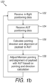
- Figure 1b is a flow diagram illustrating an example gimbal stabilisation process 120 for use with a gimbal stabilisation system 104 with controller 112 mounted on an aircraft 102 (e.g. UAV) of figure 1a according to some embodiments of the invention.
- aircraft 102 e.g. UAV
- reference numerals in relation to figure 1a will be used for similar or the same components and/or features and the like.
- the gimbal stabilisation process 120 may include the following steps of: In step 122, receiving data representative of an in-flight position of the aircraft 102 during testing of the AUT 106; In step 124, receiving data representative of a position of the AUT 106 in relation to the aircraft 102; In step 126, calculating a pointing direction and/or alignment of the first section 108a of the payload 108 of the aircraft 102 relative to the AUT 106 based on the received data representative of the position of the aircraft 102 and the position of the AUT 106; In step 128, adjusting and/or maintaining pointing and/or alignment of the first section 108a of the payload 108 towards the AUT 106 based on the calculated pointing direction and/or alignment of the first section 108a of the payload 108.
- the step of 126 may further include one or more of the following: calculating the theoretical angles for yaw, pitch and roll of the payload 108 in relation to the AUT 106; calculating drift offsets of the gimbal assembly 104b based on comparing feedback from data representative of current received position of the aircraft 102 and with attitude and heading reference system of the aircraft 102 for correcting drift in the gimbal assembly 104b; and sending angle commands and drift offsets to a gimbal controller for controlling the first, second and/or third rotation mechanisms based on combining drift offsets with theoretical angles for yaw, pitch and roll.
- the first, second and/or third rotation mechanisms may be a yaw motor, a pitch motor, and/or roll motor, respectively.
- a yaw motor or first rotation mechanism
- a pitch motor or second rotation mechanism
- a roll motor or third rotation mechanism
- the gimbal stabilisation system, apparatus and/or method(s) as described herein may use other mechanisms or means capable or operable for rotating and/or moving the required parts of the gimbal stabilisation system for controlling the pointing and/or alignment of the first section 108a of the payload 108 in the direction of the AUT 106 and/or as the application demands.
- the third rotation mechanism e.g. roll motor
- the position of the AUT 106 may be based on using a base station 115 that is located at a geometric/geographic position relative to the AUT 106. That is, the base station 115 may be located a known distance and heading 116 from the AUT 106.
- the geometric/geographic position of the base station 115 or the location of the base station 115 may be used to define a reference position for the aircraft 102 during testing of the AUT 106.
- the aircraft 102 only needs to have an accurate position estimate of the base station 115 from which it can infer or calculate an accurate position estimate of the AUT 106 during the calculations for maintaining pointing/alignment of the payload 108 to the AUT 106.
- receiving the position of the AUT 106 may further include: receiving data representative of the position of the base station 108; calculating the position of the AUT 106 based on the position of the base station 115 relative to the geometric/geographic position of the AUT 106 using a known distance 116 and/or heading of the base station 115 from the AUT 106.
- the aircraft 102 may further include other types of positioning systems or sensors and/or processing capabilities for use in determining the positioning of the AUT 106 in relation to the aircraft 102.
- the aircraft 102 may further include a camera or imaging system, which may be part of the payload 108 or part of the airframe of the aircraft 102, where images are processed in real-time to identify those images with the AUT 106. Given the timestamp of the image(s) and identified position within the images of the AUT 106, the imaging system may determine a current position estimate of the AUT 106 and send this positioning information to the controller 112.
- the AUT 106 may be tracked visually using image processing techniques and the control of the pointing / alignment of the first section 108a of the payload 108 in the direction of the AUT 106 is maintained and/or adjusted accordingly.
- the camera or imaging system may be located at the first section 108a of the payload 108, where the step 122 of receiving the position of the AUT 106 may further include: analysing one or more image(s) captured by the camera/imaging system to identify a position of the AUT 106 within the image(s); and calculating the geographic/geometric position of the AUT 106 based on the identified position of the AUT 106 in said one or more analysed images.
- analysing one or more image(s) from the camera to identify a position of the AUT 106 may further include analysing one or more image(s) from the camera to identify the AUT 106, and calculating the position of the AUT 106 based on the position of the identified AUT 106 in said one or more analysed images.
- the imaging system may be configured to analyse or image process one or more image(s) captured by the camera of the imaging system to identify a position of the AUT 106 by, without limitation, for example analysing one or more image(s) captured by the camera to identify the base station 115, and thus calculate the position or position information of the AUT 106 based on the position of the identified base station in said one or more analysed images and based on the geometric/geographic position of the AUT 106 relative to the position of the identified base station 115.
- the position of the AUT 106 may be determined based on using a beacon signal.
- the AUT 106 may include functionality for transmitting a beacon signal
- the payload 108 or the aircraft 102 may include functionality for receiving said beacon signal.
- the controller 112 receiving data representative of the position of the AUT 106 may include receiving the beacon signal associated with the AUT 106, and determining the position of the AUT 106 relative to the aircraft 102 based on the received beacon signal.
- the controller 112 receiving data representative of position information of the AUT 106 may include the payload 108 and/or aircraft 102 (e.g.
- UAV UAV receiving the beacon signal associated with the base station 115, and determining the position of the AUT 106 based on the received beacon signal from the base station 115 and the geometric/geographic position of the AUT 106 relative to the geometric/geographic position of the base station 115.
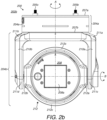
- Figures 2a to 2d are schematic diagrams illustrating various views 202a, 202b, 202c, 202d of an example gimbal stabilisation system 204 according to the invention.
- Figures 2a and 2b are schematic diagrams illustrating a side view 202a and front view 202b of the example gimbal stabilisation system 204 with a controller assembly 204a, a gimbal assembly 204b rotatably coupled to payload 208 according to the invention
- Figure 2c is a further schematic diagram illustrating a rearwards perspective view of the example gimbal stabilisation system 200 according to the invention
- Figure 2d is a further schematic diagram illustrating a side cross-sectional slice view of the example gimbal stabilisation system 200 when viewed in direction of arrow D of figure 2c according to the invention.
- the gimbal stabilisation system 200 is based on the gimbal stabilisation system 104 as described with reference to figures 1a and 1b with further modifications showing further example structural features of the control assembly 202, gimbal assembly 204 and/or payload 208 of gimbal stabilisation system 200.
- the control assembly 204a and gimbal assembly 204b are configured to provide 3 axes or degrees of freedom to enable a first section 208a of the payload 208 of the gimbal assembly 204b to be controlled and adjusted to maintain its direction and/or alignment with an AUT during an APE procedure.
- the payload 208 includes a first section 208a of the payload 208 and a second section 208b of the payload 208, where the second section 208b of the payload 208 is rotatably coupled to the gimbal assembly 204b.
- the gimbal stabilisation system 200 includes the control assembly 204a that is rotatably coupled to the gimbal assembly 204b by a first rotating mechanism, (e.g. a yaw motor), and is rotatable about a first axis of rotation A (e.g. yaw axis of rotation in relation to the control assembly 204a) in relation to the control assembly 204a.
- the control assembly 204a includes a housing with a first surface 207a and a second surface 207b. In this example, the first surface 207a is spaced apart from the second surface 207b and substantially parallel to the second surface 207a of the housing of the control assembly 204a.
- the first axis of rotation A is also substantially orthogonal to the first and second surfaces 207a and 207b of the control assembly 204a.
- the control assembly 204a includes one or more mounting mechanisms 205a-205d on the first surface 207a of the control assembly 204a.
- the mounting mechanism(s) 205a-205d include a plurality of mounting bolts or fixings configured for mounting the gimbal stabilisation system 200 to, without limitation, for example the airframe of an aircraft (e.g. a UAV).
- the gimbal assembly 204b is rotatably coupled, using the first rotation mechanism, to the control assembly 204a via the second surface 207b of the control assembly 204a.
- the gimbal assembly 204b includes a yaw arm assembly 210 with a first yaw rotating arm 210a and second yaw rotating arm 210b connected to the yaw arm assembly 210.
- the yaw arm assembly 210 may include the yaw motor in which a yaw motor shaft connects to via the second surface 207b of the control assembly 204a, or the control assembly 204a may include a yaw motor in which the yaw motor shaft connects to the yaw arm assembly 210.
- the yaw motor when activated it rotates the yaw motor shaft about the first axis of rotation A such that the yaw assembly 210 rotates about the first axis of rotation A.
- a first section 211a of the first yaw rotating arm 210a is connected a first portion of the yaw rotation assembly 210 and a first section 211b of the second yaw rotating arm 210b is connected to another portion of the yaw rotation assembly 210.
- both the first and second yaw rotation arms 210a and 210b also rotate about the first axis of rotation A (e.g. a yaw axis of rotation).
- the first yaw rotation arm 210a extends outwardly from the yaw assembly 210 in direction substantially along the first axis of rotation A and a direction away from the second surface 207b of the control assembly 204a.
- the second yaw rotation arm 210b extends in a similar manner as the first yaw rotation arm 210a.
- a second section 211c of the first yaw rotation arm 210a that is distal to the first section 211a of the first yaw rotation arm 210a.
- the second section 211c of the first yaw rotation arm 210a is rotatably coupled to a first pitch arm 212a of a pitch rotation arm assembly 212.
- the second yaw rotation arm 210b has a second section 211d of the second yaw rotation arm 210b that is distal to the first section 211b of the second yaw rotation arm 210b.
- the second section 211d of the second yaw rotation arm 210b is rotatably coupled to a second pitch arm 212b of the pitch rotation arm assembly 212.
- Both the second sections 211c and 211d of the first and second yaw rotation arms 210a and 210b, respectively, are configured to be rotatably coupled to the first and second pitch arms 212a and 212b of the pitch rotation assembly 212 such that the first and second pitch arms 212a and 212b may rotate around the same second axis of rotation B (e.g. a pitch axis of rotation).
- the second axis of rotation B is substantially orthogonal to the first axis of rotation A.
- the second section 211c of the first yaw rotating arm 210a may be rotatably coupled to the first pitch arm 212a of the pitch rotation arm assembly 212 via a pitch motor, whilst the second section 211d of the second yaw rotation arm may be rotatably coupled to the second pitch arm 212b of the pitch rotation assembly 212 via a bearing and the like in which the pitch motor may be used to controllably rotate the pitch rotation assembly 212 about the second axis of rotation B.
- both the second section 211c of the first yaw rotating arm 210a and the second section 211d of the second yaw rotation arm may be rotatably coupled to the first pitch arm 212a and second pitch arm 212b, respectively, of the pitch rotation arm assembly 212 via corresponding pitch motors, which may be controllable to rotate the pitch arm assembly 212 about the second axis of rotation B.
- This may be at an end of the yaw rotating arm 210a that is distal to the coupling of the yaw rotating arm 210a to the yaw assembly 210 and/or yaw motor and the like.
- the pitch rotating assembly 212 further includes a pitch rotation ring 212c that is configured to guide the payload 208 for rotation about a third axis of rotation C (e.g. a roll axis of rotation), where the third axis of rotation C is substantially orthogonal or perpendicular to the second axis of rotation B.
- the rear section 212d of the pitch rotating assembly is coupled to a roll motor assembly 214 including a roll motor 214a configured to rotate the payload 208, when coupled to the roll motor 214a in region of second section 208b of the payload 208, about the third axis of rotation C (e.g. the roll axis of rotation).
- the payload 208 has three degrees of freedom in relation to the yaw axis, pitch axis, and roll axis.
- the payload 208 may include a communication sensor interface for use in an APE procedure in relation to an AUT.
- the communication sensor interface of payload 208 includes a pseudo-satellite assembly for simulating a satellite during an APE procedure in relation to an AUT.
- the control assembly includes a controller that is electrically connected to the yaw motor, the pitch motor and roll motor 214a and is configured to adjust and/or the yaw motor, pitch motor and roll motor 214a for maintaining the pointing and/or alignment of the first section 208a of the payload 208 in the direction towards a ground-based target such as, without limitation, an AUT and/or other base station unit and the like as described with reference to figures 1a and/or 1b, 3a-3c and 5, and/or as herein described with and/or as the application demands.
- a ground-based target such as, without limitation, an AUT and/or other base station unit and the like as described with reference to figures 1a and/or 1b, 3a-3c and 5, and/or as herein described with and/or as the application demands.
- the controller is configured to control one or more of the yaw motor, pitch motor, and roll motor 214 based on a calculated adjustment in the pointing direction and/or alignment of the first section 208a of the payload 208 towards, without limitation, for example the AUT.
- the pseudo-satellite assembly of the payload 208 may include, without limitation, for example a signal generator 215a in region of the second section 208b of the payload 208, a dual polarised feed horn 215b (e.g. with 10dBi Gain) and Radome 215c in the region of the first section 208a of the payload 208, and the like, which are connected together to simulate a satellite transceiver.
- a signal generator 215a in region of the second section 208b of the payload 208 e.g. with 10dBi Gain
- Radome 215c e.g. with 10dBi Gain
- the payload 208 may further include, without limitation, for example GPS antenna 215d, 10MHz GPSDO module 215e; inertial movement/measurement unit (IMU) 215f; for use in determining/providing the positioning information of the aircraft and/or the gimbal stabilisation system 200 that is mounted to the aircraft and/or any drift or position information associated with the gimbal stabilisation system 200.
- the pseudo-satellite assembly of the payload 208 may be used to test AUT that normally communicate with the payload of satellites.
- the gimbal stabilisation system 200 is mounted on an aircraft such as, without limitation, for example a UAV, the UAV may act as a pseudo satellite "bus" (e.g.
- satellites are composed of a "bus" and a payload, which is carried by the "bus") and the payload 208 of the gimbal stabilisation system 200 is a pseudo-satellite assembly payload.
- the UAV may be controlled to use the pseudo-satellite assembly payload 208 to determine the pointing accuracy and/or performance of the AUT during an APE procedure.
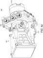
- Another example payload 208 is shown, by way of example only but the invention is not so limited, as described with reference to figures 4a and 4b .
- the payload 208 is described as being a pseudo-satellite assembly, this is by way of example only and the invention is not so limited, it is to be appreciated by the skilled person in the art that the payload 208 may be any type of communication interface or communication sensor interface for use in one or more APE procedures in relation to an AUT that is capable of being mounted/coupled to the roll motor of the gimbal assembly 204b and the like.
- the gimbal stabilisation system 200 configuration provides the payload 208 with 3 degrees of freedom, where these 3 degrees of freedom is illustrated in figures 2a-2d to be in a specific order for efficient and effective operation of the gimbal assembly 104b.
- the order of the axis of rotation of the 3 degrees of freedom is as follows, from the top: Yaw (e.g. first axis of rotation A), Pitch (e.g. second axis of rotation B), and Roll (e.g. third axis of rotation C).
- Yaw e.g. first axis of rotation A
- Pitch e.g. second axis of rotation B
- Roll e.g. third axis of rotation C.
- the specific structure that is outlined in figures 2a-2d illustrates is a preferred example of the gimbal assembly 104a structure that is built around these three axes in relation to the payload 208.
- this structure with the yaw, pitch and roll axes and coupling of the yaw, pitch and roll motors provides the best manoeuvrability of the payload 208 to ensure it can be pointed and/or aligned with the AUT for most, if not all, flight paths and/or attitude that a UAV (or other aircraft) may take and/or experience when performing APE procedures on an AUT.
- the structure and/or design of the gimbal stabilisation system 200 may be modified further to include, without limitation, for example a different ordering of two, three or more axes of rotation in the corresponding two, three or more degrees of freedom and/or as the application demands.
- the gimbal stabilisation system 200 includes a control assembly 204a and a gimbal assembly 204b.
- the control assembly 204a is an electronics housing that includes, without limitation, for example circuit boards (e.g. one or more controllers) and an electrical harness interface with the UAV (or other aircraft structure) and/or the gimbal assembly 204b.
- the control assembly 204a includes the mounting system 205a-205d for mounting the gimbal stabilisation system 200 to a UAV, which may further include a vibration dampening system.
- the vibration dampening system may absorb vibrations coming from the UAV which could otherwise cause issues for communication interfaces, sensors and vibrations in the structure of the gimbal stabilisation assembly 200.
- the gimbal assembly 204b is attached to the control assembly 204a via a yaw motor which connects to the yaw rotating arm assembly 210 of the gimbal assembly 204b.
- the structure of the gimbal assembly 204a may be reinforced internally using composite plates through the yaw rotating arms 210a and 210b, and the remaining structural elements 212, 212a-212d may be, without limitation, for example made of a non-conductive polymer material and/or any other material that can withstand UAV vibrations whilst holding the payload.
- a pitch motor may be located, where the second section 211d of the second yaw rotating arm 210b on the opposite side of the gimbal assembly 204b may be located a bearing and axle assembly.
- Attached to the pitch motor within the second section 211c is the pitch assembly 212 that includes pitch rotating arms 212a, 212b and/or pitch rotating ring 212d, which provides structural support to the payload 208 housing and an adjustable sliding shoe for the pitch rotating arm 212c.
- the payload 208 in this example, is a pseudo-satellite.
- the pitch rotating arm 212a or 212b can be adjusted in the pitch rotating ring 212c to balance the payload 208 (e.g. pseudo-satellite assembly) around the second axis of rotation C (e.g. pitch axis).
- the payload 208 may be powered by the UAV through an interface cable inside of the electrical housing of the control assembly 204a.
- the controller operations of the UAV may be powered and/or performed by a controller that may include, without limitation, for example a gimbal controller board and a microcomputer which is integrated on a motherboard in the electrical housing of the control assembly 204a.
- the motherboard distributes power and signal channels between, without limitation, for example the gimbal controller board, microcomputer, motors of the control/gimbal assemblies 204a/204b, encoders, sensors, and serial connections to devices in the payload 208.
- An electrical harness is connected to the motherboard in the control assembly 204a, which runs through the gimbal assembly 204b and yaw assembly 210 (e.g.
- the harness terminates in the rear section 212d of the pitch assembly 212 such as, without limitation, for example pitch rotating arm 212c.
- a roll motor assembly 214 is coupled or attached to the rear section 212d of the pitch assembly 212, the roll motor assembly 214 including, without limitation, for example a roll motor 214a and corresponding N-channel slip ring 214b.
- the payload 208 is attached via a second section 208b of the payload 208 to the roll motor assembly 214.
- the connection through to the second section 208a of the payload 208 of the pseudo-satellite assembly may be via, without limitation, for example the N-channel slip ring 214b (e.g. a 12-channel slip ring), located inside the roll motor assembly 214, which includes the roll motor 214a etc.
- the external cables from the slip ring 214b (stationary) is connected to a harness interface PCB on the pitch rotating arm 212a/212b
- the rotating cables from the slip ring 214b are connected to the second section 208b of the payload 208, which in this case may be the power and signal distribution board on the rear of the frequency synthesizer housing (e.g. signal generator 215a) of the pseudo satellite assembly of the payload 208.
- the power and signal distribution board may convert power from the motherboard and distributes the serial connections to devices and sensors from the controller of the controller assembly 204a, the controller includes, without limitation, for example a microcontroller and/or a gimbal controller and the like.
- the payload 208 includes a communication interface and/or communication sensor interface.
- the communication interface may include, without limitation, for example an RF system including a dual channel microwave signal generator 215a located in the region of the second section 208b of the payload 208, the second section 208b being coupled to the roll motor 214a of the roll motor assembly 214 and a dual polarized linear feedhorn 215b located in the region of the first section 208a of the payload. It is the first section 208a of the payload 208 that is directed by the controller using the control assembly 204a and/or gimbal assembly 204b to point and/or be aligned in the direction of the AUT during an APE.
- the payload 208 may further include a GPS disciplined oscillator (GPSDO) 215e including, without limitation, for example a 10MHz reference clock.
- GPSDO GPS disciplined oscillator
- the signal generator 215a can supply a clean wave signal at a single frequency between 10MHz and 24GHz. The amplitude of the signal generator can be adjusted from -40dBm to +18dBm.
- the signal generator 215a is frequency stabilised using a 10MHz GPSDO 215e. This module is connected to a GPS antenna 215d, and the 10MHz reference signal output is connected to the signal generator 215a.
- Each channel of the signal generator 215a is connected to each individual channel on the linear polarized feedhorn 215b of the first section 208a of the payload 208.
- the feedhorn 215b is a linear polarized dual channel feedhorn 215b.
- the two linear polarized channels are perpendicular to each other.
- the gain of the feedhorn 215b is rated at typical 12dB, with a 3dB beam width of 77-24° (depending on frequency) and cross polar isolation of min. 30dB.
- a weather protecting Radome 215c is attached on the front of the feedhorn 215b.
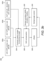
- FIG 3a is a schematic diagram illustrating another example gimbal stabilisation system 300 for use in testing an AUT according to some embodiments of the invention.
- the gimbal stabilisation system 300 is based on the gimbal stabilisation system 104, 200 as described with reference to figures 1a to 2d , modifications thereto, combinations thereof and/or as the application demands.
- the gimbal stabilisation system 300 is coupled to a UAV 302 and includes a control assembly 304a and a gimbal assembly 304b for controlling payload 308.
- the control assembly 304a is connected to the UAV 302, gimbal assembly 304b and the payload 308.
- the control assembly 304a includes a controller that includes, in this example, a microcontroller 305a and gimbal controller 305b connected together.
- the control assembly 304a is further connected to the gimbal assembly 304b, which includes a yaw motor 310a, pitch motor 310b, and roll motor 310c connected to the gimbal controller 305b and that are configured to adjust, direct and/or maintain the pointing and/or alignment of the first section 308a of the payload 308 towards an AUT during an APE procedure under control of the gimbal controller 305b and/or the microcontroller 305a.
- the first section 308a of the payload 308 may be a feedhorn and the second section 308b of the payload 308, which is connected to the feedhorn, may be a frequency synthesizer, which is also connected to the microcontroller 305a of the controller of the control assembly 304a.
- An inertial measurement unit (IMU) 312 of the gimbal assembly 304b may be connected to the gimbal controller 305b for providing AHRS data for use in determining adjustments to the yaw, pitch and roll motors 310a-310c.
- the yaw, pitch, and roll motors 310a-310c may also feedback motor positions to the gimbal controller 305b for use in determining adjustments required.
- the gimbal controller 305b of the gimbal stabilisation system 300 may be powered by a gimbal microcontroller board, which may be connected via a serial interface to microcontroller 305a (e.g. a microcomputer).
- the gimbal controller 305b is connected to motors 310a-310c of the control assembly 304a and/or gimbal assembly 304b, and sensors such as, without limitation, for example inertial measurement unit (IMU) 312 and/or absolute encoders.
- IMU inertial measurement unit
- the gimbal controller 305b may include one or more gimbal control modules/components and/or gimbal control software/hardware that uses a feedback loop control with information from sensors 312 and/or motors 310a-310c to control the motors 310a-301c which in turn moves, without limitation, for example the gimbal yaw rotation assembly, yaw rotation arms, pitch rotation assembly, pitch rotation arms, pitch rotation ring, roll assembly and/or other gimbal joint structures.
- the primary function for the gimbal controller 305a is to stabilize the gimbal assembly/control assembly against external movements of the UAV (e.g. flight path, attitude, air turbulence, heading, direction, etc.
- a secondary function for the gimbal controller 305b is to accept movement commands from the microcontroller 305a (e.g. an on-board microcomputer).
- the microcontroller 305a includes software/hardware components that is configured to sends commands for movement to the gimbal controller 305b.
- the controller of the control assembly 304a includes the microcontroller 305a and the gimbal controller 305b.
- the controller is configured to operate to receive position information (e.g. GPS/AHRS data associated with UAV/aircraft and/or AUT and the like) associated with the UAV/aircraft and receive position information associated with the AUT, compute adjustments to the rotation mechanisms (e.g.
- the gimbal assembly/control assembly for maintaining pointing/alignment of the feedhorn 308a of the payload 308 of the gimbal stabilisation system 300 in the direction of the AUT during APE procedures in which the microcontroller 305a operates frequency synthesizer 308b/308a accordingly for performing APE tests and the like.
- the microcontroller 305a is configured to receive and/or retrieve position information of the UAV and/or position information associated with the AUT based on, without limitation, for example global positioning system (GPS) and/or attitude heading reference system (AHRS) of the UAV and/or AUT and the like.
- GPS global positioning system
- AHRS attitude heading reference system
- positional information associated with the AUT may be derived from other sources and/or positional/imaging systems and the like as the application demands.
- the microcontroller 305a processes the received or retrieved position information to calculate and send commands to the gimbal microcontroller 305b which in turn is configured to control the yaw, pitch and/or roll motors 310a-310c of the gimbal assembly 304b to point the payload 308 (e.g. feedhorn 308a) of the gimbal assembly 304b at a predefined positional coordinate (e.g. GPS coordinate) associated with the AUT.
- a predefined positional coordinate e.g. GPS coordinate
- the microcontroller 305a is also able to command the gimbal controller 305b in any way which can be defined by the user of the UAV/aircraft using the gimbal stabilisation system 300, this may include, without limitation, for example polarization adjustment and/or calibration procedures and the like as the application demands.
- the microcontroller 305a and/or a microcomputer of the UAV may be configured to store data including, without limitation, for example flight data, RF data positional data, and/or other data required by the APE procedure for analysing the AUT and the like from sensors (e.g.
- the UAV/aircraft which can be used for real-time processing and/or post processing and plotting performance of the AUT, without limitation, for example, AUT RF radiation patterns, beam lobes, pointing, directionality, alignment and any other properties, parameters and/or characteristics of the AUT that requires performance evaluation and the like and/or as the application demands.
- Figure 3b is a flow diagram illustrating another example gimbal stabilisation process 320 for use with gimbal stabilisation system 300 of figure 3a and/or gimbal stabilisation systems 100 and/or 200 as described with reference to figures 1a to 2d , combinations thereof, modifications thereto and/or as described herein according to some embodiments of the invention.
- the gimbal stabilisation process 320 may be performed by the controller of the gimbal stabilisation system 300, which includes, by way of example only but is not limited to, a microcontroller 305a and a gimbal controller 305b.
- the microcontroller 305a may perform most of the processing in relation to determining the corrections required for the gimbal assembly 304b to direct and/or maintain the pointing of the payload 308 (e.g. feedhorn 308a of the payload 308) and/or alignment of the payload 308 with the AUT.
- the gimbal stabilisation process 320 may include the following steps of: In step 322a receiving positional information associated with the aircraft/UAV such as, without limitation, for example UAV GPS position and altitude. In step 322b, receiving positional information associated with the AUT such as, without limitation for example AUT GPS position and/or altitude.
- step 322c receiving further positional information associated with the AUT and/or APE procedure being performed on the AUT including, without limitation, for example AUT Azimuth, AUT elevation, and/or AUT polarisation.
- step 324 processing the received positional information associated with the UAV/aircraft and the AUT received in steps 322a-322c in which relative angles for pointing a first section 308a of the payload 308 (e.g. feedhorn) at a target (e.g. the AUT) are calculated.
- the target may be the AUT that is being tested during an APE procedure.
- a pointing direction and/or alignment of the first section 308a of the payload 308 relative to the AUT based on the received positional information of the UAV and/or AUT may be calculated. This is then used to control the yaw, pitch and roll motors 310a-310b of the gimbal assembly 304b. In step 326, drift compensation is also calculated based on the current computed angles and/or motor positions 310a-310c fed back from the gimbal assembly controller 305b in step 332.
- step 328 one or more offsets are computed based on the relative angles and computed drift compensation of steps 324 and 326, the offsets may be used to control and adjust the yaw, pitch and/or roll motors of the gimbal assembly 304b to adjust the pointing and/or alignment of the payload 308 in relation to the AUT.
- step 330 angle commands, drift compensation, and/or gimbal angle control instructions are sent to the gimbal controller 305b, which performs motor control of the yaw, pitch and/or roll motors 310a-310c of the gimbal assembly 304b in accordance with the received angle commands, drift compensation, and/or gimbal angle control instructions.
- the gimbal assembly 304b may also provide status/positional feedback including data representative of, without limitation, for example the gimbal yaw, pitch and/or roll motor encoders, yaw, pitch and/or roll motor positions, and/or AHRS data of the UAV such as, without limitation, for example heading, attitude, and other flight data of the UAV.
- the status/positional feedback data associated with the gimbal assembly 304b may be received from the gimbal controller 305b (e.g. data representative of AHRS, encoders, heading, attitude etc.), which is fed into the drift compensation step 326 for calculating drift associated with the position of the motors and/or UAV and the like, which may be combined with the required relative angles for pointing the payload at the target (e.g. AUT).
- the target e.g. AUT
- the gimbal stabilisation process 320 operates, in steps 322a-322c, by taking positional data from the UAV and AUT in relation to GPS position, heading and attitude and information about the AUT. With this positional data the gimbal stabilisation process 320 in step 324 calculates the theoretical angles for yaw, pitch, and roll required to ensure the payload 308 is pointing towards and/or aligned with the AUT.
- a drift compensation routine/algorithm checks any received feedback data that the gimbal controller 305a receives from the yaw, pitch, roll motors 310a-310c and/or IMU 312 and other sensors, which includes data representative of motor positions, current UAV heading and attitude and the like and compares it with, for example, the UAV compass system and/or GPS coordinates and the like. In this way the gimbal stabilisation process 320 is configured to correct any potential drift in the system with reference to the UAV AHRS and GPS position.
- offsets associated with any drift that is to be compensated for in relation to the yaw, pitch and/or roll motors 310a-310c and/or position of the UAV can be applied to the computed angles, which are then output, in step 330 to the gimbal controller 305b as angle commands/instructions etc.
- the offsets applied can be based on, without limitation, for example, constant offsets, mechanical structure offsets or sensor misplacement/miscalibration and the like.
- the gimbal controller 305b sends control instructions to the yaw, pitch and/or roll motors 310a-310c in relation to the corresponding angle instructions/commands from the microcontroller 305a.
- the gimbal stabilisation process 320 may be performed by the microcontroller 305a and/or in part by gimbal controller 305b.
- the controller of the control assembly is described and illustrated with reference to a microcontroller 305a and a gimbal controller 305b, this is by way of example only and the invention is not so limited, the skilled person in the art would understand that the controller of the gimbal stabilisation system 300 may be implemented using, without limitation, for example one or more processors, sensors, microcontroller(s) and/or any other hardware/software solution, combination thereof, modifications thereto and/or as the application demands.
- FIG. 3c is a schematic diagram illustrating a UAV testing system 340 using the gimbal stabilisation process 320 of figure 3b and gimbal stabilisation system 300 in an APR procedure in relation to an AUT 342 according to some embodiments of the invention.
- the UAV testing system 340 is configured for testing linear polarized antenna systems, thus the gimbal stabilisation process 320 and payload 308 are further modified to take into account ensuring alignment of the payload 308 of the UAV 302 with the AUT 342 whilst the UAV 302 traverses a flight path/route 344 during the APE procedure. This is to ensure there is polarisation alignment between the feedhorn 308a of the payload 308 and the corresponding antenna of the AUT 342.
- the gimbal stabilisation system 300 and process 320 may be further modified to track the attitude of the feedhorn 308a and/or the gimbal assembly 304b to ensure the feedhorn 308a is in alignment with the linear polarised antenna of the AUT 342.
- the UAV 302 testing system 340 is testing a linear polarised antenna of an AUT 342 in which the UAV 302 traverses a flight path arc 344.
- the UAV 302 is represented by crosses made up of orthogonal H polarisation and V polarisation lines 302a and 302b, respectively, (referred to as UAV H-V cross 302a/302b) which represent the orientation of the feedhorn 308a of the UAV payload 308.
- the linear polarised antenna of the AUT 342 also has H polarisation and V polarisation lines 342a and 342b, respectively, (referred to as AUT H-V cross 342a/342b.
- the UAV H-V cross 302a/302b is misaligned with the AUT H-V cross 342a/342b, thus the feedhorn 308a of the payload 308 may not be performing an accurate APE procedure.
- feedhorn 308a alignment of the UAV payload 308 is required for accurate testing of linear polarized antenna systems. In such scenarios, not only should the first section 308a of the payload 308 (e.g.
- the feedhorn 308a of the payload 308) be pointing in the direction of the AUT 342 as the UAV traverses flight path arc 344, it should also align the AUT feed polarization with the test probe/feedhorn polarization of the payload 308. That is, the UAV H-V cross 302a/302b should also align with the AUT H-V cross 342a/342b.
- the AUT 342 has an elevation angle of >0°, there will be a relative polarization angle difference as the UAV 302 moves/flies around the AUT 342 with respect to ground. In this case, to ensure the polarization is aligned, i.e. the UAV H-V cross 302a/302b is aligned with the AUT H-V cross 342a/342b, the feedhorn 308a angle with respect to ground must also change accordingly.
- the gimbal stabilisation process 320 may include the further modifications of:
- step 324 of gimbal stabilisation process 320 which may be performed by microcontroller 305a, can be further modified to control the polarisation alignment of the payload 308 based on: reading the GPS position from the UAV 302; comparing the GPS position of the UAV 302 with the AUT GPS coordinates; calculating a theoretical alignment angle through which the feedhorn 308a of the payload 308 should be adjusted towards based on the comparison; and/or calculating a theoretical roll adjustment value based on the comparison; and in step 330 sending an roll angle instruction/command (e.g.
- the gimbal controller 305b may receive the roll angle instruction/command and control/operate the roll motor 310a of the gimbal assembly 304b to adjust its orientation accordingly.
- the feedhorn 308a of the UAV 302 may be brought into alignment with the polarisation. Should the UAV 302 move outside of the principal planes (e.g.
- a mathematical method of polarisation adjustment may instead be applied in step 324 for calculating a correcting roll (polarization) angle for the transmitting probe or feedhorn 308a of the payload 308 on the UAV 302.
- the principal behind the mathematical method of polarisation adjustment is described in the article by A. Ludwig, "The definition of cross polarization,” in IEEE Transactions on Antennas and Propagation, vol. 21, no. 1, pp. 116-119, January 1973 .
- Figures 4a and 4b are schematic diagrams illustrating perspective views 402 and 404, respectively, of an example payload 400 for use with gimbal stabilisation systems 100, 200 and/or 300 as described with reference to figures 1a to 3c , modifications thereof, combinations thereto, and/or as herein described according to some embodiments of the invention.
- the payload 400 is a pseudo-satellite assembly (or a directional horn and signal generator/receiver assembly) and is similar or the same as the example payload 208 of gimbal stabilisation system 200 as described with reference to figures 2a to 2d .
- the reference numerals of figures 2a to 2d may be reused for the same and/or similar components.
- the roll motor 214a of the roll motor assembly 214 is shown attached to the pseudo-satellite assembly 400.
- the roll motor 214a is attached to the roll motor assembly 214 of the pitch rotating ring 212c of the pitch rotating assembly 212 of the gimbal assembly 204b.
- the pseudo-satellite assembly 400 includes a power and signal distribution PCB board 406 as viewed in figure 4b , an RF signal generator 408 (or frequency synthesizer) covered by a load bearing RF signal generator housing to which a dual polarized feedhorn 410 is also attached.
- the pseudo-satellite assembly 400 may be configured to generate a Ku-band continuous wave (CW) test signal for APE procedures with AUT in which the UAV simulates a satellite.
- CW Ku-band continuous wave
- UAV-APE payload 400 as described here based on generating a Ku-band continuous wave (CW) test signal (e.g. type 1), this is by way of example only and the invention is not so limited, it is to be appreciated by the skilled person that there are many other variants of payload 400 that may use the same or similar principals such as, without limitation, for example one or more of: a UAV-APE type 1 payload that is configured to generate a Ku-band continuous wave test signal; a UAV-APE type 2 payload that is configured to generate Ka-band single frequency or modulated signal; a UAV-APE type 3 payload that is configured to combine linear polarization RF transmission from the feedhorn to produce a circular polarized signal; a UAV-APE type 4 payload that is configured to generate Ku-band single frequency or modulated signal; a UAV-APE type 5 payload that is configured as a combination of electronic and mechanical steered beam (phased array antenna); a UAV-APE type 6 payload that
- UAV-APE payload 400 has been described to be configurable and/or operable for using various types of Ku/Ka-band continuous wave test signals and the like in different types of APE tests, this is by way of example only and the invention is not so limited, it is to be appreciated by the skilled person in the art that UAV-APE payload 400 may be configured to include any type of communication interface/communication sensor interface is a transceiver, receiver, and/or transmitter and be controllable to generate, transmit and/or receive, without limitation, a communications signal, test signal, RF signal, continuous wave and the like and/or as the application demand in any desired one or more frequencies, and/or any desired one or more polarisations and the like.
- any type of communication interface/communication sensor interface is a transceiver, receiver, and/or transmitter and be controllable to generate, transmit and/or receive, without limitation, a communications signal, test signal, RF signal, continuous wave and the like and/or as the application demand in any desired one or more frequencies, and/or any desired
- the transceiver, receiver and/or transmitter of the payload 400 may be operable to perform, where relevant, at least one or more from the group of: generate and transmit a continuous wave or modulated test signal in a desired frequency; receive a continuous wave or modulated test signal in a desired frequency; generate and transmit a linearly polarised signal to the AUT; generate and transmit a circularly polarised signal to the AUT; receive a linearly polarised signal from the AUT; and receive a circularly polarised signal from the AUT; any other generation, transmission and/or reception of a signal or wave and the like based on / or as required by the type of APE used for testing the antenna of the AUT and/or as the application demands.
- FIG. 5 is a schematic diagram illustrating an example UAV test system 500 using a UAV 502 for an APE test procedure for an AUT 506, where the UAV 502 is configured to use a gimbal stabilisation system 100, 200, 300, as described with reference to figures 1a to 4b , modifications thereto, combinations thereof, and/or as herein described according to some embodiments of the invention.
- the UAVtest system 500 is configured to use a UAV 502 to perform an APE procedure in relation to AUT 506. Prior to the APE test procedure, the UAV test system 500 needs to be set up.
- a user of the UAV 502 e.g.
- a technician, operator, APE test operator and the like may arrive on the test site 501 on which the AUT 506 is located in which an antenna of the AUT 506 is to be tested.
- the user may bring a UAV (e.g. a drone) with the gimbal stabilisation system 100, 200, 300 and/or as described herein mounted thereon.
- the gimbal stabilisation system has a suitable payload configured for the test in the gimbal assembly.
- Other test equipment and a base station 504 may also be provided by the user.
- the base station 504 may include a control station for receiving, without limitation, for example any RF measurements, flight data and the like from UAV 502 for real-time and/or subsequent analysis in relation to the APE procedure of the AUT 506.
- the base station 504 may also be configured to control the operation and flight path/route of the UAV 502 during an APE procedure with the AUT 506 and the like.
- the base station 504 may be a portable device.
- the based station 504 may be a real-time kinematic (RTK) base station, which is the reference position for the UAV test system 500. As such, it will remain in the same location throughout the APE tests and may be used to compute the local positioning error. This also allows the UAV (e.g. drone) 502 to know where it is and assists the UAV 502 to perform an accurate automated flight in respect of the APE procedure when testing the AUT 506. The user may also measure the position of the antenna of the AUT 506 with reference to the RTK base station 504. This will then ensure that the antenna of the AUT 506 is at the centre of all measurement flight paths.
- RTK real-time kinematic
- the user may also identify and define the test environment 501 by choosing a safe take-off and landing spot for the UAV 502, as well as for deciding on the placement, if necessary, of the AUT 506 (if it is portable enough, or not already in-situ or installed in a vehicle and the like) and any other equipment required for the APE procedure.
- the AUT 506 can be prepared for the APE testing procedure. This may include, without limitation, for example identifying its position, ensuring proper functionality during the test, and placing the test receiving equipment on the AUT 506 and the like.
- the UAV 502 can be configured traverse a flight path that performs a raster scan measurement in which the correct Az and El angles of the AUT 506 are identified. Further verifications may be performed to ensure optimal accuracy.
- the UAV APE test may be performed.
- the user may, in real-time, guide the UAV flight path to perform any desired measurements based on the APE test, whilst the gimbal stabilisation assembly automatically maintains/adjusts the pointing of the first section of the payload (e.g. feedhorn) of the UAV 502 in the direction of the AUT 506 and/or maintains/adjusts the alignment (e.g. polarisation alignment) of the first section of the payload (e.g. feedhorn) of the UAV 502 with that of the antenna of the AUT 506.
- the gimbal stabilisation assembly automatically maintains/adjusts the pointing of the first section of the payload (e.g. feedhorn) of the UAV 502 in the direction of the AUT 506 and/or maintains/adjusts the alignment (e.g. polarisation alignment) of the first section of the payload (e.g. feedhorn) of the UAV 502 with that of the antenna of the AUT 5
- the user does not need to adjust or continually compensate the position of the payload based on the flight path and/or attitude of the UAV 502 and the like. Instead, the user can concentrate on performing the APE test. For example, the user may plan numerous APE tests based on, without limitation, for example one or more of: an Azimuth cut 508, Elevation cut 510 or a Raster scan, as well as change the frequency and signal amplitude of the feedhorn of the payload in the gimbal assembly of the gimbal stabilisation system mounted on the UAV 502.
- An APE test may be performed by manually and/or automatically performing real-time guidance of the flight path of the UAV 502 whilst in flight.
- the UAV 502 may be configured to take any desired measurement for performing the APE test in relation to the AUT 506 such as, without limitation, for example: performing an Azimuth cut 508, an Elevation cut 510, and/or Raster scan, and/or any other flight path or cut and the like, whilst varying frequencies and signal amplitudes of the feedhorn of the payload etc.
- the first test results returned from the UAV 502 may reveal how directive an antenna of the AUT 506 is and/or, in addition, provide enough information for displaying the shape of the radiation pattern of the AUT 506.
- the measurement of the actual antenna gain is achieved by using different methods determined by the final desired measurement accuracy.
- a pattern cut may be performed in which a preprogramed test route, with the UAV 502 following a flight path that maintains a constant distance between the AUT 506 (based on the main beam 512 Az and El) and each RF data point measured and collected, and transmitted/stored for further processing by, without limitation, for example the base station 504 and the like.
- the UAV 502 and received signal status may be constantly monitored and the results generated can be graphically plotted for visual inspection or provided in data format.
- the power recorder is relative, in dBm, and essentially the first set of results may reveal how directive an antenna of an AUT 506 is and the shape of the radiation pattern.
- Further test methods may be required to, without limitation, for example perform one or more of: measure the actual antenna gain; apply the correct mask, where one can either use a known gain antenna; or calculate the gain using the 3 dB beam width rule; and/or carefully calculate the link budget of the system; and/or any other type of test and the like as the application demands.
- the chosen test method is dependent on the final desired measurement accuracy.
- Another type of test method, such as a pattern cut may be performed by the UAV over a pre-programmed test route.
- the route may be built/designed as a semi-circular line in front of the AUT 506 (based on the main beam 512 Az and El) and with all points at an equal distance towards the AUT 506.
- the flight speed of the UAV 502 may be determined by a factor of distance from AUT 506 and the number of desired collected data points for analysis.
- the status of the UAV 502 and received signal are monitored from the base station 504 (e.g. ground control station).
- the system may record the UAV GNSS position.
- the receive measurement equipment can record in the peak power level (PPL) mode.
- the results are generated by combining the information regarding the antenna pointing and position with the UAV 502 position and the recorded power level.
- the results can either be graphically plotted for visual inspection or provided in data format for use in other third-party software.
- UAV 502 to perform APE test procedures in relation to an AUT 506 may provide many advantages such as, for example, UAV 502 flexibility and manoeuvrability; simulating motion in relation to the AUT 506; selecting the environment as well as the direction and elevation of the antenna; UAV 502 allows the measurement to be done in a wider range of far field distances, ranging from few dozens of meters to kilometres; and/or portability.
- UAV(s) with the gimbal stabilisation system as described with reference to figures 1a to 6b for performing antenna performance evaluation (APE) procedures provides the advantage of enabling an accurate, cost effective and portable method of testing the performance of an AUT in situ, at a test site, and/or at a test site prior to installation and the like.
- the weight of the gimbal stabilisation system with payload for performing APE's on AUTs is within the UAV payload capability range.
- UAVs are more cost effective than manned aircraft, and the size of UAVs means they are easily transportable to any location where the AUT may be tested.
- FIG. 6a is a schematic diagram illustrating an example computing system 600 that comprises at least one computing device 602 that may be used to implement one or more aspects of the gimbal stabilisation system, UAV, aircraft, controller and/or any other aspects according to the invention and/or includes the methods/process(es)/system(s) and apparatus as described with reference to figures 1a-5 .
- Computing device 602 includes one or more processor unit(s) 604, memory unit 606 and communication interface 608 in which the one or more processor unit(s) 604 are connected to the memory unit 606 and the communication interface 608.
- the communications interface 608 may connect the computing device 602 to one or more other device(s), command and control unit(s), one or more sensor(s), RF station(s), external or cloud storage or processing system(s) and the like.
- the memory unit 606 may store one or more program instructions, code or components such as, by way of example only but not limited to, an operating system 606a for operating computing device 602 and a data store 606b for storing additional data and/or further program instructions, code and/or components associated with implementing the functionality and/or one or more function(s) or functionality associated with the gimbal stabilisation system and/or functionality of one or more of the controller assembly, gimbal assembly, controller, yaw, pitch and/or roll motors, flight control system(s) and/or payload, method(s), process(es), any other functionality of the aircraft/UAV, APE procedures as described with reference to figures 1a- 5 , combinations thereof, modifications thereof and/or as described herein and the like according to the invention.
- the memory unit may include a computer-readable medium with data or instruction code, which when executed on the processor unit, causes the processor unit to implement the functionality of the controller, control assembly, gimbal assembly and/or gimbal stabilisation system, process(es)/method(s) as described herein and/or modifications thereof.
- the apparatus or computing device may be further configured to implement the functionality of the gimbal stabilisation system, UAV/aircraft, a user interface and/or the sensor suite/payload or interface with the sensor suite/payload as described herein and/or modifications thereof.
- FIG. 6b is a schematic diagram illustrating an example UAV-APE system 610 with a gimbal stabilisation system 612 according to some embodiments of the invention.
- the gimbal stabilisation system 612 for an aircraft/UAV including a control assembly rotatably coupled to a gimbal assembly including a payload, the control assembly including a controller configured for receiving positioning information associated with the UAV and/or an AUT during an APE from positioning UAV/AUT module(s) 614, the controller further including gimbal/payload control module/component 616 configured to operate the control assembly/gimbal assembly and/or yaw, pitch and/or roll motor(s) of the gimbal stabilisation system based on the positioning information and to adjust/maintain pointing and/or alignment of a first section of the payload in the direction or towards an AUT, where a second section of the payload is rotatably coupled to the gimbal assembly of the gimbal stabilisation system 612.
- the UAV/controller may be further configured to include a test/control AUT module 618 configured to operate the payload and/or perform an APE procedure in relation to the AUT.
- the first section of payload includes a communication interface/communication sensor interface for use in testing the AUT during the APE procedure and the like.
- the gimbal stabilisation system 612 include the functionality, process(es), method(s), apparatus, control assembly, gimbal assembly, payload, and other sensors/communication sensors and the like as described with reference to figures 1a to 6b , combinations thereof, modifications thereto, and/or as described herein, and/or as the application demands.
- FIG. 1 may include one or more apparatus and/or devices that include a communications interface, a memory unit, and a processor unit, the processor unit connected to the communications interface and the memory unit, wherein the processor unit, storage unit, communications interface are configured to perform or implement the functionality of the gimbal stabilisation system controller/control assembly, gimbal assembly, flight control system(s), yaw, pitch and/or roll motors/control, method(s), process(es), any other functionality of the gimbal stabilisation system, payload and/or UAV/aircraft as described with reference to figures 1a to 6b , combinations thereof, modifications thereof and/or as described herein.
- the processor unit, storage unit, communications interface are configured to perform or implement the functionality of the gimbal stabilisation system controller/control assembly, gimbal assembly, flight control system(s), yaw, pitch and/or roll motors/control, method(s), process(es), any other functionality of the gimbal stabilisation system, payload and/or UAV/aircraft
- the flight control system and/or the operations control centre may include computing device(s) and/or one or more server(s), which may comprise a single server or a network of servers.
- the functionality or parts of the functionality of the computing device and/or server may be provided by a network of servers distributed across a geographical area, such as a worldwide distributed network of servers, and a user may be connected to an appropriate one of the network of servers based upon a user location.
- a computer-readable medium including data or instruction code, which when executed on one or more processor(s), causes the one or more processor(s) to implement the functionality and/or one or more function(s) or functionality associated with the gimbal stabilisation system, control assembly, gimbal assembly, yaw, pitch and/or roll motors, method(s), process(es), any other functionality of the UAV/aircraft, payload, operations centre/command and control stations, as described with reference to figures 1a to 6b , combinations thereof, modifications thereof and/or as described herein and the like according to the invention.
- the server may comprise a single server or network of servers.
- the functionality of the server may be provided by a network of servers distributed across a geographical area, such as a worldwide distributed network of servers, and a user may be connected to an appropriate one of the network of servers based upon a user location.
- the system may be implemented as any form of a computing and/or electronic device.
- a device may comprise one or more processors which may be microprocessors, controllers or any other suitable type of processors for processing computer executable instructions to control the operation of the device in order to gather and record routing information.
- the processors may include one or more fixed function blocks (also referred to as accelerators) which implement a part of the method in hardware (rather than software or firmware).
- Platform software comprising an operating system or any other suitable platform software may be provided at the computing-based device to enable application software to be executed on the device.
- Computer-readable media may include, for example, computer-readable storage media.
- Computer-readable storage media may include volatile or non-volatile, removable or non-removable media implemented in any method or technology for storage of information such as computer readable instructions, data structures, program modules or other data.
- a computer-readable storage media can be any available storage media that may be accessed by a computer.
- Such computer-readable storage media may comprise RAM, ROM, EEPROM, flash memory or other memory devices, CD-ROM or other optical disc storage, magnetic disc storage or other magnetic storage devices, or any other medium that can be used to carry or store desired program code in the form of instructions or data structures and that can be accessed by a computer.
- Disc and disk include compact disc (CD), laser disc, optical disc, digital versatile disc (DVD), floppy disk, and blu-ray disc (BD).
- BD blu-ray disc
- Computer-readable media also includes communication media including any medium that facilitates transfer of a computer program from one place to another.
- a connection for instance, can be a communication medium.
- the software is transmitted from a website, server, or other remote source using a coaxial cable, fiber optic cable, twisted pair, DSL, or wireless technologies such as infrared, radio, and microwave are included in the definition of communication medium.
- a coaxial cable, fiber optic cable, twisted pair, DSL, or wireless technologies such as infrared, radio, and microwave are included in the definition of communication medium.
- hardware logic components may include Field-programmable Gate Arrays (FPGAs), Application-Program-specific Integrated Circuits (ASICs), Application-Program-specific Standard Products (ASSPs), System-on-a-chip systems (SOCs), Complex Programmable Logic Devices (CPLDs), etc.
- FPGAs Field-programmable Gate Arrays
- ASICs Application-Program-specific Integrated Circuits
- ASSPs Application-Program-specific Standard Products
- SOCs System-on-a-chip systems
- CPLDs Complex Programmable Logic Devices
- the computing device may be a distributed system. Thus, for instance, several devices may be in communication by way of a network connection and may collectively perform tasks described as being performed by the computing device.
- the computing device may be located remotely and accessed via a network or other communication link (for example using a communication interface).
- 'computer' is used herein to refer to any device with processing capability such that it can execute instructions. Those skilled in the art will realise that such processing capabilities are incorporated into many different devices and therefore the term 'computer' includes PCs, servers, mobile telephones, personal digital assistants and many other devices.
- a remote computer may store an example of the process described as software.
- a local or terminal computer may access the remote computer and download a part or all of the software to run the program.
- the local computer may download pieces of the software as needed, or execute some software instructions at the local terminal and some at the remote computer (or computer network).
- a dedicated circuit such as a DSP, programmable logic array, or the like.
- any reference to 'an' item refers to one or more of those items.
- the term 'comprising' is used herein to mean including the method steps or elements identified, but that such steps or elements do not comprise an exclusive list and a method or apparatus may contain additional steps or elements.
- the terms "component” and “system” are intended to encompass computer-readable data storage that is configured with computer-executable instructions that cause certain functionality to be performed when executed by a processor.
- the computer-executable instructions may include a routine, a function, or the like. It is also to be understood that a component or system may be localized on a single device or distributed across several devices.
- the acts described herein may comprise computer-executable instructions that can be implemented by one or more processors and/or stored on a computer-readable medium or media.
- the computer-executable instructions can include routines, sub-routines, programs, threads of execution, and/or the like.
- results of acts of the methods can be stored in a computer-readable medium, displayed on a display device, and/or the like.
Landscapes
- Engineering & Computer Science (AREA)
- General Engineering & Computer Science (AREA)
- Mechanical Engineering (AREA)
- Aviation & Aerospace Engineering (AREA)
- Radar, Positioning & Navigation (AREA)
- Remote Sensing (AREA)
- Physics & Mathematics (AREA)
- General Physics & Mathematics (AREA)
- Automation & Control Theory (AREA)
- Details Of Aerials (AREA)
- Position Fixing By Use Of Radio Waves (AREA)
Claims (15)
- Computerimplementiertes Verfahren zum Steuern eines Kardanstabilisierungssystems (104) eines Luftfahrzeugs (102) in einem Antennentestsystem (100) zum Testen einer Antenne unter Test, AUT (106), wobei das Kardanstabilisierungssystem (104) eine Steuerbaugruppe (104a) umfasst, die drehbar mit einer Kardanbaugruppe (104b) gekoppelt ist, die eine Nutzlast (108) umfasst, wobei die Nutzlast (108) einen ersten Abschnitt (108a), der eine Kommunikationssensorschnittstelle zur Verwendung beim Testen der AUT (106) beinhaltet, und einen zweiten Abschnitt (108b) umfasst, wobei die Nutzlast (108) drehbar mit der Kardanbaugruppe (104b) gekoppelt ist, wobei die Steuerbaugruppe (104a) eine Steuereinheit (112) umfasst, das Verfahren, das von der Steuereinheit (112) durchgeführt wird, weiter umfassend:Empfangen einer Flugposition des Luftfahrzeugs (102) während Testens der AUT (106);wobei das Verfahren dadurch gekennzeichnet ist, dass es weiter Folgendes umfasst:Empfangen einer Position der AUT (106) in Bezug auf das Luftfahrzeug (102); undSteuern der Kardanbaugruppe (104b) durch:Berechnen einer Zeigerichtung und Ausrichtung des ersten Abschnitts (108a) der Nutzlast (108) relativ zu der AUT (106) auf Grundlage der empfangenen Position des Luftfahrzeugs (102) und der empfangenen Position der AUT (106); undAufrechterhalten der Zeigerichtung und Ausrichtung des ersten Abschnitts (108a) der Nutzlast (108) gegenüber der AUT (106) auf Grundlage der berechneten Zeigerichtung und Ausrichtung des ersten Abschnitts (108a) der Nutzlast (108), weiter umfassend:
Steuern der Zeigerichtung und der Ausrichtung des ersten Abschnitts (108a) der Nutzlast (108) um mindestens drei Drehachsen, wobei eine Drehachse der mindestens drei Drehachsen konfiguriert ist, um die Ausrichtung des ersten Abschnitts (108a) der Nutzlast zu steuern, wobei die Ausrichtung des ersten Abschnitts (108a) der Nutzlast (108) eine Polarisationsausrichtung der Kommunikationssensorschnittstelle umfasst. - Computerimplementiertes Verfahren nach Anspruch 1, wobei Empfangen der Flugposition des Luftfahrzeugs weiter Empfangen von Daten umfasst, die für ein globales Positionierungssystem, GPS, Position, Kurs, Höhe und/oder Lage des Luftfahrzeugs repräsentativ sind; und/oderweiter umfassend Empfangen der Position der AUT, weiter umfassend Empfangen von Daten, die für Informationen repräsentativ sind, die der Position der AUT zugeordnet sind; und/oderwobei die Kommunikationssensorschnittstelle weiter mindestens eines aus der Gruppe umfasst von:einem Empfänger;einem Sender;einem Sender-Empfänger;und/oder jeglicher anderen Kommunikationsschnittstelle und/oder Kommunikationssensorschnittstelle, die zum Testen der AUT konfiguriert ist.
- Computerimplementiertes Verfahren nach einem der Ansprüche 1 bis 2, wobei die Steuerbaugruppe durch einen ersten Motor drehbar mit der Kardanbaugruppe gekoppelt ist, wobei die Kardanbaugruppe weiter Folgendes umfasst:einen ersten Dreharm, der mit dem ersten Motor gekoppelt ist, wobei der erste Motor dazu konfiguriert ist, den ersten Dreharm um eine erste Drehachse zu drehen, wobei der erste Dreharm mit einem zweiten Motor an einem Ende des ersten Dreharms gekoppelt ist, das distal zu der Kopplung des ersten Dreharms mit dem ersten Motor ist;einen zweiten Dreharm, der mit dem zweiten Motor gekoppelt ist, wobei der zweite Motor dazu konfiguriert ist, den zweiten Dreharm um eine zweite Drehachse zu drehen, wobei die zweite Drehachse orthogonal zu der ersten Drehachse ist, wobei der zweite Dreharm mit einem dritten Motor gekoppelt ist, wobei der dritte Motor dazu konfiguriert ist, die Nutzlast, die an den dritten Motor an dem zweiten Abschnitt der Nutzlast gekoppelt ist, um eine dritte Drehachse zu drehen, wobei sich die dritte Drehachse von der zweiten Drehachse unterscheidet; unddie Steuereinheit der Steuerbaugruppe, die elektrisch mit dem ersten Motor, dem zweiten Motor und dritten Motor verbunden ist;wobei Steuern der Kardanbaugruppe weiter umfasst:
Aufrechterhalten der Zeigerichtung und Ausrichtung des ersten Abschnitts der Nutzlast, weiter umfassend Steuern eines oder mehrerer des ersten Motors, zweiten Motors und dritten Motors auf Grundlage der berechneten Zeigerichtung und Ausrichtung des ersten Abschnitts der Nutzlast gegenüber der AUT. - Computerimplementiertes Verfahren nach Anspruch 3, wobei die erste Drehachse eine Gier-Drehachse in Bezug auf die Kardanbaugruppe ist, die zweite Drehachse eine Nick-Drehachse in Bezug auf die Kardanbaugruppe ist und die dritte Achse eine Roll-Drehachse in Bezug auf die Kardanbaugruppe ist; und/oderwobei der erste, zweite und dritte Motor jeweils mindestens einen aus der Gruppe umfassen von: einem Kardanmotor; einem bürstenlosen Motor; einem bürstenlosen Kardanmotor; einem Kardanantriebsmotor; und/oder einem beliebigen geeigneten Motor zur Verwendung beim Einstellen und/oder Aufrechterhalten der Zeigerichtung und/oder Ausrichtung des ersten Nutzlastabschnitts in der Richtung der AUT; und/oderwobei der erste, zweite und dritte Motor einem Giermotor, Nickmotor beziehungsweise Rollmotor entsprechen.
- Computerimplementiertes Verfahren nach einem der Ansprüche 3 bis 4, wobei Steuern der Kardanbaugruppe weiter Folgendes umfasst:Berechnen der theoretischen Gier-, Nick- und Rollwinkel der Nutzlast in Bezug auf die AUT;Berechnen von Drift-Offsets der Kardanbaugruppe auf Grundlage vom Vergleichen von Rückmeldung aus Daten, die für die aktuell empfangene Position des Luftfahrzeugs repräsentativ sind, und mit einem Lage- und Kursreferenzsystem des Luftfahrzeugs, um Drift in der Kardanbaugruppe zu korrigieren; undSenden von Winkelbefehlen und Drift-Offsets an eine Kardansteuereinheit zum Steuern eines oder mehrerer des ersten Motors, zweiten Motors und dritten Motoren auf Grundlage vom Kombinieren von Drift-Offsets mit theoretischen Gier-, Nick- und Rollwinkeln.
- Computerimplementiertes Verfahren nach einem der Ansprüche 3 bis 5, wobei Steuern der Kardanbaugruppe weiter Folgendes umfasst:
wenn die Nutzlast zum Testen linear polarisierter Systeme verwendet wird, Steuern der Kardanbaugruppe, um eine Polarisationsausrichtung der Polarisation der Nutzlastkommunikationssensorschnittstelle mit der AUT-Polarisation durch Folgendes beizubehalten:Vergleichen der empfangenen Flugposition des Luftfahrzeugs mit der empfangenen Position der AUT;Berechnen eines theoretischen Rollanpassungswerts, um zumindest den Rollwinkel der Nutzlast in Bezug auf die AUT auf Grundlage des Vergleichs zum Aufrechterhalten einer Polarisationsausrichtung anzupassen; undSenden eines Rollwinkelbefehls an den Rollmotor der Kardanbaugruppe. - Computerimplementiertes Verfahren nach einem vorstehenden Anspruch, wobei sich eine Basisstation an einer geographischen Position relativ zu der AUT befindet, wobei der Ort der Basisstation eine Referenzposition für das Luftfahrzeug während Testens der AUT definiert, und wobei Empfangen der Position der AUT weiter umfasst:Empfangen der Position der Basisstation;Berechnen der Position der AUT auf Grundlage der geographischen Position der AUT relativ zu der Position der Basisstation.
- Computerimplementiertes Verfahren nach einem vorstehenden Anspruch, wobei die Nutzlast weiter eine Kamera umfasst, die sich an dem ersten Ende der Nutzlast befindet, und wobei Empfangen der Position der AUT weiter umfasst:Analysieren eines oder mehrerer Bilder von der Kamera, um eine Position der AUT zu identifizieren; undBerechnen der Position der AUT auf Grundlage der identifizierten Position der AUT in dem einen oder den mehreren analysierten Bildern; undwobei:Analysieren eines oder mehrerer Bilder von der Kamera, um eine Position der AUT zu identifizieren, weiter Analysieren eines oder mehrerer Bilder von der Kamera umfasst, um die AUT zu identifizieren; undBerechnen der Position der AUT auf Grundlage der Position der identifizierten AUT in dem einen oder den mehreren analysierten Bildern; undwenn abhängig von Anspruch 7, wobei:Analysieren eines oder mehrerer Bilder von der Kamera, um eine Position der AUT zu identifizieren, weiter Analysieren eines oder mehrerer Bilder von der Kamera umfasst, um die Basisstation zu identifizieren; undBerechnen der Position der AUT auf Grundlage der Position der identifizierten Basisstation in dem einen oder den mehreren analysierten Bildern und auf Grundlage der geographischen Position der AUT relativ zu der Position der identifizierten Basisstation.
- Computerimplementiertes Verfahren nach einem vorstehenden Anspruch, wobei die AUT ein Beacon-Signal beinhaltet, und wobei Empfangen der Position der AUT weiter umfasst:Empfangen des der AUT zugeordneten Beacon-Signals; undBestimmen der Position der AUT auf Grundlage des empfangenen Beacon-Signals.
- Computerimplementiertes Verfahren nach einem der Ansprüche 8 bis 9, wenn von Anspruch 7 abhängig, wobei die Basisstation ein Beacon-Signal beinhaltet, und wobei Empfangen der Position der AUT weiter umfasst:Empfangen des der Basisstation zugeordneten Beacon-Signals; undErmitteln der Position der AUT auf Grundlage des von der Basisstation empfangenen Beacon-Signals und der geographischen Position der AUT relativ zu der Position der Basisstation.
- Computerimplementiertes Verfahren nach einem vorstehenden Anspruch, das weiter Aufrechterhalten der Zeigerichtung des ersten Abschnitts der Nutzlast zu einer bestimmten Position in Bezug auf die AUT umfasst.
- Kardanstabilisierungssystem (104) für ein Luftfahrzeug (102), umfassend eine Steuerbaugruppe (104a), die drehbar mit einer Kardanbaugruppe (104b) gekoppelt ist, die eine Nutzlast (108) umfasst, wobei die Steuerbaugruppe (104a) eine Steuereinheit (112) umfasst, die dazu konfiguriert ist, die Kardanbaugruppe (104b) zu betreiben, um eine Zeigerichtung eines ersten Abschnitts (108a) der Nutzlast (108) gegenüber einer im Antenne unter Test, AUT (106), beizubehalten, wobei ein zweiter Abschnitt (108b) der Nutzlast (108) drehbar mit der Kardanbaugruppe (104b) gekoppelt ist, wobei der erste Abschnitt (108a) eine Kommunikationssensorschnittstelle zur Verwendung beim Testen der AUT (106) umfasst; und
wobei die Kardanbaugruppe (104b) weiter Betreiben der Steuereinheit (112) des Kardanstabilisierungssystems (104) auf Grundlage des computerimplementierten Verfahrens nach einem der Ansprüche 1 bis 11 umfasst. - Einrichtung, die eine Prozessoreinheit, eine Speichereinheit und eine Kommunikationsschnittstelle umfasst, wobei die Prozessoreinheit mit der Speichereinheit und der Kommunikationsschnittstelle verbunden ist, wobei die Prozessoreinheit, die Speichereinheit und die Kommunikationsschnittstelle dazu geeignet sind, das computerimplementierte Verfahren nach einem der Ansprüche 1 bis 11 zu implementieren.
- System, umfassend:ein Luftfahrzeug (102), das eine Kardanstabilisierungseinrichtung nach Anspruch 13 umfasst; undeine Antenne unter Test (106),wobei das Luftfahrzeug (102) dazu konfiguriert ist, Testen der AUT (106) unter Verwendung der Kardanstabilisierungseinrichtung durchzuführen; und wobei das Luftfahrzeug (102) ein unbemanntes Luftfahrzeug ist.
- Computerlesbares Medium, umfassend darauf gespeicherten Computercode oder darauf gespeicherte Befehle, der/die, wenn er/sie auf einem Prozessor ausgeführt wird/werden, den Prozessor veranlasst/veranlassen, das Verfahren nach Anspruch 1 bis 11 durchzuführen.
Applications Claiming Priority (2)
| Application Number | Priority Date | Filing Date | Title |
|---|---|---|---|
| GB2012756.9A GB2611503A (en) | 2020-08-14 | 2020-08-14 | Gimbal stabilisation system |
| PCT/EP2021/072560 WO2022034200A1 (en) | 2020-08-14 | 2021-08-12 | Gimbal stabilisation system |
Publications (3)
| Publication Number | Publication Date |
|---|---|
| EP4196858A1 EP4196858A1 (de) | 2023-06-21 |
| EP4196858C0 EP4196858C0 (de) | 2024-10-02 |
| EP4196858B1 true EP4196858B1 (de) | 2024-10-02 |
Family
ID=72615462
Family Applications (1)
| Application Number | Title | Priority Date | Filing Date |
|---|---|---|---|
| EP21765599.2A Active EP4196858B1 (de) | 2020-08-14 | 2021-08-12 | Kardanisches stabilisierungssystem |
Country Status (6)
| Country | Link |
|---|---|
| US (1) | US12618507B2 (de) |
| EP (1) | EP4196858B1 (de) |
| CN (1) | CN116711324A (de) |
| ES (1) | ES2994977T3 (de) |
| GB (2) | GB2611503A (de) |
| WO (1) | WO2022034200A1 (de) |
Families Citing this family (5)
| Publication number | Priority date | Publication date | Assignee | Title |
|---|---|---|---|---|
| GB2611503A (en) | 2020-08-14 | 2023-04-12 | Quadsat Aps | Gimbal stabilisation system |
| CN115059837B (zh) * | 2022-06-09 | 2023-06-02 | 广州后作科技有限公司 | 一种激光测绘仪专用可避障式旋转支架 |
| CN115009515B (zh) * | 2022-06-20 | 2024-06-14 | 南京航空航天大学 | 一种高抗风多涵道式系留无人机及其控制方法 |
| GB202303672D0 (en) * | 2023-03-13 | 2023-04-26 | Quadsat Aps | Airborne satellite orbital simulator |
| WO2025102063A1 (en) * | 2023-11-10 | 2025-05-15 | The Board Of Regents Of The University Of Oklahoma | Uncrewed aerial system for measuring antenna radiation patterns |
Family Cites Families (9)
| Publication number | Priority date | Publication date | Assignee | Title |
|---|---|---|---|---|
| CN107923567B (zh) * | 2015-07-02 | 2020-07-31 | 深圳市大疆灵眸科技有限公司 | 用于图像捕捉的云台 |
| CN113581464A (zh) * | 2015-09-11 | 2021-11-02 | 深圳市大疆灵眸科技有限公司 | 用于无人飞行器的载体 |
| CN106953553A (zh) | 2017-03-12 | 2017-07-14 | 纳恩博(北京)科技有限公司 | 一种云台、及云台电机的控制方法和装置 |
| WO2019084709A1 (zh) * | 2017-10-30 | 2019-05-09 | 深圳市大疆创新科技有限公司 | 控制云台的方法、云台、控制系统和可移动设备 |
| RU2704393C1 (ru) | 2019-01-17 | 2019-10-28 | Акционерное общество "Радиокомпания "Вектор" | Способ автоматизированной ориентации бортовой антенны беспилотного комплекса для измерений параметров направленности антенн |
| CN110927467A (zh) * | 2019-12-02 | 2020-03-27 | 中电科特种飞机系统工程有限公司 | 一种外场天线测试系统及一种外场天线测试方法 |
| CN111537965B (zh) * | 2020-04-28 | 2020-11-03 | 中国气象局气象探测中心 | 一种基于无人机的天气雷达标定方法及系统 |
| GB2611503A (en) | 2020-08-14 | 2023-04-12 | Quadsat Aps | Gimbal stabilisation system |
| US11783713B2 (en) * | 2021-05-06 | 2023-10-10 | Nanjing University Of Aeronautics And Astronautics | Method and device for measuring four-dimensional (4D) radiation pattern of outdoor antenna based on unmanned aerial vehicle (UAV) |
-
2020
- 2020-08-14 GB GB2012756.9A patent/GB2611503A/en active Pending
-
2021
- 2021-08-12 GB GB2302104.1A patent/GB2612527A/en not_active Withdrawn
- 2021-08-12 US US18/021,378 patent/US12618507B2/en active Active
- 2021-08-12 CN CN202180070690.6A patent/CN116711324A/zh active Pending
- 2021-08-12 WO PCT/EP2021/072560 patent/WO2022034200A1/en not_active Ceased
- 2021-08-12 ES ES21765599T patent/ES2994977T3/es active Active
- 2021-08-12 EP EP21765599.2A patent/EP4196858B1/de active Active
Non-Patent Citations (1)
| Title |
|---|
| DUTHOIT SIMON ET AL: "UAV-BASED IN SITU ANTENNA CHARACTERIZATION: ANALYSIS AND DESIGN REQUIREMENTS A THESIS APPROVED FOR THE SCHOOL OF ELECTRICAL AND COMPUTER ENGINEERING", 11 May 2018 (2018-05-11), Norman, Oklahoma, pages 1 - 157, XP093142452, Retrieved from the Internet <URL:https://hdl.handle.net/11244/299790> [retrieved on 20240318] * |
Also Published As
| Publication number | Publication date |
|---|---|
| GB2611503A (en) | 2023-04-12 |
| US20230313938A1 (en) | 2023-10-05 |
| GB2612527A (en) | 2023-05-03 |
| EP4196858A1 (de) | 2023-06-21 |
| GB202012756D0 (en) | 2020-09-30 |
| EP4196858C0 (de) | 2024-10-02 |
| CN116711324A (zh) | 2023-09-05 |
| GB202302104D0 (en) | 2023-03-29 |
| US12618507B2 (en) | 2026-05-05 |
| WO2022034200A1 (en) | 2022-02-17 |
| ES2994977T3 (en) | 2025-02-05 |
Similar Documents
| Publication | Publication Date | Title |
|---|---|---|
| US12618507B2 (en) | Gimbal stabilisation system | |
| US11435483B2 (en) | System for testing the accuracy of the automatic positioning means of a signal tracking antenna | |
| US7333064B1 (en) | System and method for pointing and control of an antenna | |
| US5880693A (en) | Method and apparatus for the wireless exchange of information between stations | |
| KR101485486B1 (ko) | 지향성 무선 통신시스템의 안테나 자동 정렬 유지장치 및 그 방법 | |
| US20160088498A1 (en) | Unmanned aerial vehicle for antenna radiation characterization | |
| KR102809028B1 (ko) | 항공기 내비게이션 및 감시 시스템들의 엔드-투-엔드 무인 제어 시스템 | |
| US20260072065A1 (en) | Airborne satellite orbital simulator | |
| Nugroho et al. | Design, manufacture and performance analysis of an automatic antenna tracker for an unmanned aerial vehicle (UAV) | |
| CN110741272A (zh) | 无线电信标系统 | |
| JP2020186960A (ja) | 測位方法および測位システム | |
| KR101824707B1 (ko) | 드론을 이용한 초단파 전방향 무선표지 신호 분석 시스템 | |
| RU2704393C1 (ru) | Способ автоматизированной ориентации бортовой антенны беспилотного комплекса для измерений параметров направленности антенн | |
| CN111912404B (zh) | 飞行设备输出姿态修正系统及方法 | |
| RU190804U1 (ru) | Устройство для обеспечения навигации и посадки корабельных летательных аппаратов | |
| KR101129255B1 (ko) | 자세 센서를 이용한 gps 안테나용 능동형 짐벌 | |
| EP3018834B1 (de) | Systeme und verfahren zur bereitstellung von indikatoren zur steuerung eines flugzeuges | |
| Jenvey et al. | A portable monopulse tracking antenna for UAV communications | |
| Sollie et al. | Automatic recovery of fixed-wing unmanned aerial vehicle using Bluetooth angle-of-arrival navigation | |
| KR20190107772A (ko) | 드론을 이용한 거리정보장치 신호 분석 시스템 | |
| RU2836791C2 (ru) | Способ контроля диаграммы направленности антенны облетным методом с помощью БПЛА | |
| KR102841155B1 (ko) | 위상 배열 안테나의 위성 탐색 및 추적 방법 | |
| RU2799550C1 (ru) | Способ и комплексная автоматизированная система управления авиационными системами наблюдения и навигации | |
| WO2025102063A9 (en) | Uncrewed aerial system for measuring antenna radiation patterns | |
| Zavrorodnij et al. | Estimation of the Coordinates of an Unmanned Aircraft in the Tasks of Determining the Radiation Pattern of a Satellite Antenna |
Legal Events
| Date | Code | Title | Description |
|---|---|---|---|
| STAA | Information on the status of an ep patent application or granted ep patent |
Free format text: STATUS: UNKNOWN |
|
| STAA | Information on the status of an ep patent application or granted ep patent |
Free format text: STATUS: THE INTERNATIONAL PUBLICATION HAS BEEN MADE |
|
| PUAI | Public reference made under article 153(3) epc to a published international application that has entered the european phase |
Free format text: ORIGINAL CODE: 0009012 |
|
| STAA | Information on the status of an ep patent application or granted ep patent |
Free format text: STATUS: REQUEST FOR EXAMINATION WAS MADE |
|
| 17P | Request for examination filed |
Effective date: 20230214 |
|
| AK | Designated contracting states |
Kind code of ref document: A1 Designated state(s): AL AT BE BG CH CY CZ DE DK EE ES FI FR GB GR HR HU IE IS IT LI LT LU LV MC MK MT NL NO PL PT RO RS SE SI SK SM TR |
|
| DAV | Request for validation of the european patent (deleted) | ||
| DAX | Request for extension of the european patent (deleted) | ||
| GRAP | Despatch of communication of intention to grant a patent |
Free format text: ORIGINAL CODE: EPIDOSNIGR1 |
|
| STAA | Information on the status of an ep patent application or granted ep patent |
Free format text: STATUS: GRANT OF PATENT IS INTENDED |
|
| INTG | Intention to grant announced |
Effective date: 20240502 |
|
| GRAS | Grant fee paid |
Free format text: ORIGINAL CODE: EPIDOSNIGR3 |
|
| GRAA | (expected) grant |
Free format text: ORIGINAL CODE: 0009210 |
|
| STAA | Information on the status of an ep patent application or granted ep patent |
Free format text: STATUS: THE PATENT HAS BEEN GRANTED |
|
| AK | Designated contracting states |
Kind code of ref document: B1 Designated state(s): AL AT BE BG CH CY CZ DE DK EE ES FI FR GB GR HR HU IE IS IT LI LT LU LV MC MK MT NL NO PL PT RO RS SE SI SK SM TR |
|
| REG | Reference to a national code |
Ref country code: GB Ref legal event code: FG4D |
|
| REG | Reference to a national code |
Ref country code: CH Ref legal event code: EP |
|
| REG | Reference to a national code |
Ref country code: DE Ref legal event code: R096 Ref document number: 602021019653 Country of ref document: DE |
|
| REG | Reference to a national code |
Ref country code: IE Ref legal event code: FG4D |
|
| U01 | Request for unitary effect filed |
Effective date: 20241024 |
|
| U07 | Unitary effect registered |
Designated state(s): AT BE BG DE DK EE FI FR IT LT LU LV MT NL PT RO SE SI Effective date: 20241106 |
|
| REG | Reference to a national code |
Ref country code: ES Ref legal event code: FG2A Ref document number: 2994977 Country of ref document: ES Kind code of ref document: T3 Effective date: 20250205 |
|
| PG25 | Lapsed in a contracting state [announced via postgrant information from national office to epo] |
Ref country code: IS Free format text: LAPSE BECAUSE OF FAILURE TO SUBMIT A TRANSLATION OF THE DESCRIPTION OR TO PAY THE FEE WITHIN THE PRESCRIBED TIME-LIMIT Effective date: 20250202 Ref country code: HR Free format text: LAPSE BECAUSE OF FAILURE TO SUBMIT A TRANSLATION OF THE DESCRIPTION OR TO PAY THE FEE WITHIN THE PRESCRIBED TIME-LIMIT Effective date: 20241002 |
|
| PG25 | Lapsed in a contracting state [announced via postgrant information from national office to epo] |
Ref country code: GR Free format text: LAPSE BECAUSE OF FAILURE TO SUBMIT A TRANSLATION OF THE DESCRIPTION OR TO PAY THE FEE WITHIN THE PRESCRIBED TIME-LIMIT Effective date: 20250103 |
|
| PG25 | Lapsed in a contracting state [announced via postgrant information from national office to epo] |
Ref country code: CZ Free format text: LAPSE BECAUSE OF FAILURE TO SUBMIT A TRANSLATION OF THE DESCRIPTION OR TO PAY THE FEE WITHIN THE PRESCRIBED TIME-LIMIT Effective date: 20241002 Ref country code: PL Free format text: LAPSE BECAUSE OF FAILURE TO SUBMIT A TRANSLATION OF THE DESCRIPTION OR TO PAY THE FEE WITHIN THE PRESCRIBED TIME-LIMIT Effective date: 20241002 |
|
| PG25 | Lapsed in a contracting state [announced via postgrant information from national office to epo] |
Ref country code: RS Free format text: LAPSE BECAUSE OF FAILURE TO SUBMIT A TRANSLATION OF THE DESCRIPTION OR TO PAY THE FEE WITHIN THE PRESCRIBED TIME-LIMIT Effective date: 20250102 |
|
| PG25 | Lapsed in a contracting state [announced via postgrant information from national office to epo] |
Ref country code: SM Free format text: LAPSE BECAUSE OF FAILURE TO SUBMIT A TRANSLATION OF THE DESCRIPTION OR TO PAY THE FEE WITHIN THE PRESCRIBED TIME-LIMIT Effective date: 20241002 |
|
| PGFP | Annual fee paid to national office [announced via postgrant information from national office to epo] |
Ref country code: GB Payment date: 20250626 Year of fee payment: 5 |
|
| PG25 | Lapsed in a contracting state [announced via postgrant information from national office to epo] |
Ref country code: SK Free format text: LAPSE BECAUSE OF FAILURE TO SUBMIT A TRANSLATION OF THE DESCRIPTION OR TO PAY THE FEE WITHIN THE PRESCRIBED TIME-LIMIT Effective date: 20241002 |
|
| U1N | Appointed representative for the unitary patent procedure changed after the registration of the unitary effect |
Representative=s name: CROWELL & MORING U.K. LLP; GB |
|
| PLBE | No opposition filed within time limit |
Free format text: ORIGINAL CODE: 0009261 |
|
| STAA | Information on the status of an ep patent application or granted ep patent |
Free format text: STATUS: NO OPPOSITION FILED WITHIN TIME LIMIT |
|
| U20 | Renewal fee for the european patent with unitary effect paid |
Year of fee payment: 5 Effective date: 20250709 |
|
| 26N | No opposition filed |
Effective date: 20250703 |
|
| PGFP | Annual fee paid to national office [announced via postgrant information from national office to epo] |
Ref country code: ES Payment date: 20250905 Year of fee payment: 5 |
|
| PGFP | Annual fee paid to national office [announced via postgrant information from national office to epo] |
Ref country code: NO Payment date: 20250808 Year of fee payment: 5 |
|
| PGFP | Annual fee paid to national office [announced via postgrant information from national office to epo] |
Ref country code: CH Payment date: 20250901 Year of fee payment: 5 |
|
| PG25 | Lapsed in a contracting state [announced via postgrant information from national office to epo] |
Ref country code: MC Free format text: LAPSE BECAUSE OF FAILURE TO SUBMIT A TRANSLATION OF THE DESCRIPTION OR TO PAY THE FEE WITHIN THE PRESCRIBED TIME-LIMIT Effective date: 20241002 |
|
| U1N | Appointed representative for the unitary patent procedure changed after the registration of the unitary effect |
Representative=s name: HOEIBERG P/S; DK |