EP4196844B1 - Methoden und systeme zur erzeugung von laserpulsen hoher spitzenleistung - Google Patents
Methoden und systeme zur erzeugung von laserpulsen hoher spitzenleistung Download PDFInfo
- Publication number
- EP4196844B1 EP4196844B1 EP21762001.2A EP21762001A EP4196844B1 EP 4196844 B1 EP4196844 B1 EP 4196844B1 EP 21762001 A EP21762001 A EP 21762001A EP 4196844 B1 EP4196844 B1 EP 4196844B1
- Authority
- EP
- European Patent Office
- Prior art keywords
- spatial
- laser
- electric field
- fiber
- laser pulses
- Prior art date
- Legal status (The legal status is an assumption and is not a legal conclusion. Google has not performed a legal analysis and makes no representation as to the accuracy of the status listed.)
- Active
Links
Images

Classifications
-
- G—PHYSICS
- G02—OPTICS
- G02B—OPTICAL ELEMENTS, SYSTEMS OR APPARATUS
- G02B27/00—Optical systems or apparatus not provided for by any of the groups G02B1/00 - G02B26/00, G02B30/00
- G02B27/48—Laser speckle optics
-
- G—PHYSICS
- G02—OPTICS
- G02B—OPTICAL ELEMENTS, SYSTEMS OR APPARATUS
- G02B27/00—Optical systems or apparatus not provided for by any of the groups G02B1/00 - G02B26/00, G02B30/00
- G02B27/09—Beam shaping, e.g. changing the cross-sectional area, not otherwise provided for
- G02B27/0916—Adapting the beam shape of a semiconductor light source such as a laser diode or an LED, e.g. for efficiently coupling into optical fibers
-
- G—PHYSICS
- G02—OPTICS
- G02B—OPTICAL ELEMENTS, SYSTEMS OR APPARATUS
- G02B27/00—Optical systems or apparatus not provided for by any of the groups G02B1/00 - G02B26/00, G02B30/00
- G02B27/09—Beam shaping, e.g. changing the cross-sectional area, not otherwise provided for
- G02B27/0927—Systems for changing the beam intensity distribution, e.g. Gaussian to top-hat
-
- G—PHYSICS
- G02—OPTICS
- G02B—OPTICAL ELEMENTS, SYSTEMS OR APPARATUS
- G02B27/00—Optical systems or apparatus not provided for by any of the groups G02B1/00 - G02B26/00, G02B30/00
- G02B27/09—Beam shaping, e.g. changing the cross-sectional area, not otherwise provided for
- G02B27/0938—Using specific optical elements
- G02B27/0944—Diffractive optical elements, e.g. gratings, holograms
Definitions
- the present description relates to methods and systems for the generation of high peak power laser pulses intended in particular for laser shock.
- the present description finds applications for example in laser shot peening, laser shock spectroscopy, generation of ultrasound by laser or laser cleaning of components.
- laser shock i.e. with plasma formation
- pulses of very high peak power typically around 10 megawatts (MW) or more, i.e. typically pulses whose duration is of the order of a few tens of nanoseconds or less and which have energies of more than a hundred millijoules.
- MW megawatts
- These applications include for example laser shock spectroscopy, laser cleaning, generation of ultrasound by laser, for example for the analysis of the crystal structure of a material and “laser shot peening” (or “ laser shockpeening ” according to the Anglo-Saxon expression) for improving the lifespan and mechanical resistance of parts.
- Laser peening is described for example in patents US 6002102 [ref. 1] and EP 1 528 645 [ref. 2].
- a first thin absorbent layer is placed on the part to be treated.
- high peak power laser pulses vaporize the absorbing layer which generates a hot plasma.
- the expansion of the plasma causes an intense compression wave which makes it possible to generate prestresses deep in the material of the part to be treated.
- This process called “laser peening”, makes it possible to increase the mechanical resistance of parts to cyclic fatigue. This process is generally carried out by transporting the beam in free space to the area to be treated.
- optical fibers seem to be well-suited tools.
- some of the processes previously described such as laser shot peening or laser surface cleaning, are generally carried out in dusty industrial environments and the damage thresholds of the fiber entry and exit surfaces are significantly reduced.
- the peak power level that can be injected into a fiber is limited by the dielectric damage threshold of the material constituting the core of the fiber. fiber.
- the damage threshold of the air-silica interface is around 1 GW/cm 2 .
- waveguides with large core diameters are preferred.
- large cores typically greater than 1 mm
- curvatures create losses through evanescent waves which can damage the fiber.
- a set of optical fibers can be used, as described for example in the patent US6818854 [ref. 3].
- the possibility of spatial shaping of the beam is also described to standardize the spatial power density of the pulses at the input of the fiberized device. Standardizing the spatial power density makes it possible to limit overcurrents in the fiber linked to the Gaussian intensity distribution of a beam, for example.
- a spatial pulse shaping module is described making it possible to form pulses whose spatial intensity distribution is of the square or " top hat " type according to the English expression, that is to say with a low spatial variation of intensity, typically limited to +/- 10%. Spatial shaping of the top hat type also makes it possible to adapt the light beam formed by said first pulses to the dimension of the core of the multimode fiber.
- Such a spatial shaping module may comprise a diffractive optical element (or “DOE” according to the Anglo-Saxon expression “ Diffractive Optical Element ”) associated with an optical system, for example an optical lens, to achieve shaping.
- DOE diffractive optical element
- an optical system for example an optical lens
- spatial shaping of the beam in a Fourier plane (for example the image focal plane) of the optical system corresponds to the spatial Fourier transform of the phase mask imposed by the DOE convolved with the spatial Fourier transform of the spatial distribution of beam intensity at the DOE.
- the phase mask imposed by the DOE can be calculated such that the result of this convolution forms a given intensity distribution at the entry face of the fiber, for example a “top hat” type intensity distribution, the diameter of the beam at the entry face of the fiber being proportional to the focal length of the optical system.
- the DOE associated with an optical system of the optical lens type therefore proves to be particularly interesting for the spatial shaping of nanosecond pulses in the context of the transport of pulses of high peak power since by choosing the parameters of the DOE, a laser beam , whatever its spatial distribution at the source output, can be injected into a single core fiber while respecting the size of the waveguide and its numerical aperture.
- the applicant has highlighted the appearance of overcurrents or "hot spots" linked to the presence of a DOE, the latter being able to promote local damage to the entry surface of the fiber due to too much local light density. high.
- the applicant has shown in particular that the most intense hot spots can have a peak power up to 6 times greater than the average power of a pulse injected into the fiber.
- the Fig. 1 illustrates a spatial shaping module with a diffractive optical element 20 cooperating with an optical system 21, for example an optical lens, to achieve spatial shaping adapted to the size and geometry of a multimode optical fiber 10 intended to the transport of nanosecond pulses.
- the multimode optical fiber 10 comprises a cladding 11 and a multimode core 12.
- Curve 31 represents a profile of the spatial intensity distribution of a beam formed from said nanosecond pulses.
- the spatial intensity distribution profile is measured in an input plane of the multimode optical fiber 10, by means of a detector (not shown), in arbitrary units (ua), along a measurement axis of a surface detection of the detector passing through the center of the beam.
- Image 32 shows the intensity distribution of the beam in the entry plane of the multimode optical fiber 10. As is visible on curve 31 or in image 32, overcurrents are apparent, likely to damage the fiber 10. The applicant has shown that overcurrents result from speckle type interference.
- An object of the present description is a method and a system for generating pulses of high peak power (typically around 10 MW or above), allowing injection into a single-core fiber device with even greater security, and ensuring secure propagation over long distances while making the use of flexible fibers possible.
- high peak power typically around 10 MW or above
- the term “approximately” or “substantially” is synonymous with (means the same as) a lower and/or upper margin of 10%, for example 5%, of the respective value.
- the entrance face of the multimode fiber is substantially coincident with a Fourier plane of said optical system.
- the Fourier plane is a plane where a Fourier transform of the electric field is formed and corresponds for example, in the case of a collimated beam, to a focal plane image of a lens or a mirror.
- the optical system comprises one or more lens(es) configured to form a converging optical system and/or one or more reflective optical elements, for example a converging spherical mirror or an off-axis parabolic mirror.
- the optical system may comprise one or more optical elements making it possible to focus the light to generate a Fourier plane.
- the DOE can be produced on one face of one of the optical elements of the optical system, for example engraved on a concave (or parabolic) mirror forming said optical system.
- a spatial distribution of intensity of the square or “ top hat ” type according to the present description is a spatial distribution of substantially uniform intensity, with a low spatial variation of the intensity, typically limited to +/- 10%.
- said spatial shaping module is arranged upstream of said optical system. This arrangement allows the spatial shaping module to receive a laser beam formed from said substantially collimated pulses.
- the spatial shaping module can, however, be arranged before or after the DOE.
- said spatial shaping module comprises a polarization jammer, configured to transform a first electric field into a second electric field formed from a sum of two components along two orthogonal axes, the two components having a variable phase shift along a given axis.
- variable phase shift along said axis is periodic, which results in a periodic variation of the state of polarization of the electric field at the output of the polarization jammer, and the polarization jammer is arranged in such a way that a spatial distribution of intensity of said first electric field comprises, along said axis, a dimension greater than a period of variation of the state of polarization.
- the light source is longitudinal multimode and the spatial shaping module comprises at least a first diffraction grating, configured to transform a first electric field into a second electric field formed by a sum of N components, N ⁇ 2, said N components being characterized by non-collinear wave vectors.
- N is between 2 and 10.
- said spatial shaping module comprises at least a second network arranged following said first network.
- said spatial shaping module further comprises a polarization jammer, said at least one first network being arranged before the polarization jammer.
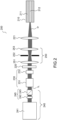
- FIG. 2 represents a simplified diagram illustrating a system 200 for generating high peak power laser pulses according to the present description.
- the system 200 comprises a light source 240 for emitting initial nanosecond laser pulses I L and a fiberized device for transporting the laser pulses, comprising at least a first multimode fiber 210 with a single core 212 and a cladding 211.
- the light source 240 comprises in this example a laser source 241, for example a Q-Switch Nd:YAG type laser for the emission of nanosecond pulses.
- the laser can be equipped with a frequency doubler module to emit at a wavelength of 532 nm.
- the laser source is for example an active or passive Q-switched solid-state laser for the emission of nanosecond pulses of high peak power (greater than 10 MW). It can be, for example, a Yb:YAG laser or even a titanium Sapphire laser depending on the wavelength at which we wish to work.
- the laser source is naturally polarized, the polarization can be linear, circular or elliptical.
- the light source 240 may contain (optionally) an attenuator of the optical emission power 245, comprising for example a half-wave plate followed by one or more polarization filter(s) (Brewster plate, Glan prism or prism by Glan Thomson for example).
- an attenuator of the optical emission power 245 comprising for example a half-wave plate followed by one or more polarization filter(s) (Brewster plate, Glan prism or prism by Glan Thomson for example).
- the system 200 further comprises a diffractive optical element (DOE) 220 and an optical system 221, the elements 220 and 221 being arranged upstream of the fiber device, and configured to generate, on an input face of said first multimode fiber 210 , from each initial laser pulse, a laser pulse at fiber input I F defined by an electric field comprising a “top hat” type spatial intensity distribution.
- the system 200 comprises for example a spatial shaping module 230 which will be described in more detail later and, in this example, a filtering device 250.
- the filtering device 250 comprises for example a set of lenses 251, 253 configured to form an intermediate focal plane in which a diaphragm 252 is arranged. Such a filtering device is configured to remove unwanted diffraction orders from the DOE (typically order 0 and all orders greater than or equal to 2).
- each initial nanosecond laser pulse I L is defined by an initial electric field a pulsation ⁇ 0 .
- the laser output field has a spatial coherence which can be qualified by a degree of coherence.
- a radiation is totally spatially coherent when the degree of coherence reaches the unity value for any pair of points. Conversely, spatial coherence tends towards 0 when the degree of coherence is low, for all pairs of points.
- One way to experimentally observe the degree of coherence of a source is to measure the contrast of an interference pattern (Young slit type or speckle pattern). The more the incident radiation is spatially coherent, the higher the contrast of the interference pattern.
- the DOE 220 comprises for example, in a known manner, in the case of a component in transmission, a plate of a material, for example silica, etched in the thickness in order to generate a spatially variable phase shift of the incident electric field to obtain, in a Fourier plane coincident with an input plane of the multimode fiber 210, that is to say in this example in a focal plane of the optical system 221, an electric field of desired amplitude.
- a plate of a material for example silica
- the optical system 221 may comprise one or more lens(es) configured to form a converging optical system and/or one or more reflective optical elements, for example a converging spherical mirror or an off-axis parabolic mirror.
- the optical system 221 may comprise one or more optical elements making it possible to focus the light to generate a Fourier plane.
- the DOE 220 can also be etched directly on one of the optical elements forming the optical system 221.
- the DOE 220 is represented in such a way as to operate in transmission, the assembly can be adapted for operation of the DOE in reflection.
- u x ⁇ f
- Functions E 0 ⁇ u v and T ⁇ ( u , v ) represent the spatial Fourier transforms in the focal plane of the lens of E 0 ( x, y, t ) and t ( x, y ) .
- the field is thus composed of a deterministic part making it possible to obtain the desired formatting and a random part attributed to the roughness of the DOE.
- We can thus write the electric field in the Fourier plane in the form of a sum of two contributions: E Out ⁇ u v S u v e 1 ⁇ + E rand u v e 1 ⁇
- E rand thus represents a random phase term in the Fourier plane of the lens due to the roughness of the DOE.
- the light intensity therefore includes a first low spatial frequency term of the top hat type and a high spatial frequency term, of random phase, which affects the shaping of the pulses in the input plane of the multimode fiber.
- the spatial shaping module 230 of the system 200 aims to reduce the contrast of the high frequency component resulting from speckle type interference on the input face of said first multimode fiber.
- ⁇ I ⁇ is the mean of the top hat light intensity and ⁇ I is the standard deviation.
- a spatial shaping module 230 arranged upstream of the fiberized device, and configured to transform a first electric field into a second electric field formed from a sum of a plurality N of components , at least partially spatially incoherent between them, made it possible to reduce the contrast of the high frequency component resulting from speckle-type interference at the input of the multimode fiber and therefore to secure the injection into the multimode fiber of strong pulses. peak power.
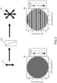
- Fig. 3 represents a simplified diagram illustrating a polarization jammer 232 configured for spatial shaping of pulses in a system according to the present description and the effects of such a polarization jammer.
- the polarization jammer is for example a Cornu depolarizer (or quartz depolarizer), a liquid crystal depolarizer or a double prism depolarizer.
- a Cornu depolarizer comprises two prisms with an angle of 45°.
- n 2 and n 1 are respectively the extraordinary and ordinary index of Quartz
- a is the length over which the two prisms are in contact
- d is the length of the depolarizer.
- E ⁇ x y z t E 0 x y t e j ⁇ 0 t ⁇ kz 2 e 1 ⁇ + e 2 ⁇ e ⁇ j 2 ⁇ ⁇ not 1 ⁇ not 2 2 y ⁇ has
- the beam when the incident beam has a uniform linear polarization, at the output of the component, the beam will have a periodic polarization in the y direction. More precisely, each spatial coordinate of the beam has a different polarization state. In the above hypothesis, along the y axis, the beam will successively present polarization states, linear, circular and elliptical with different orientations.
- the variation of the polarization state will be periodic along the y axis.
- the incident beam will advantageously present, along the y axis, a dimension greater than the period of variation of the state of polarization at the depolarizer output.
- the period of spatial variation of the polarization is 4 mm for a wavelength of 635 nm.
- the beam incident on the depolarizer has a dimension at least equal to the polarization variation period, advantageously at least equal to twice the polarization period, to obtain an effective depolarization and consequently a degree polarization which tends towards zero.
- a visualization of the effect of a depolarizer on the spatial shaping of incident pulses is illustrated in diagrams 33, 34 of the Fig. 3 .
- Diagram 33 represents the polarization state at the input of the polarizer, in this example a uniform polarization (linear polarization).
- Diagram 34 represents the polarization state at the output of the polarizer.
- a variable polarization is observed following the spatial coordinates (x,y) of the beam considered. If we consider two points A, B with coordinates (xi,yi) and (x 2 ,y 2 ) respectively, we observe a drop in the degree of normalized spatial coherence as defined by equation [MATH 2] above.
- points A and B are orthogonally polarized, thus the degree of coherence drops to 0 because the numerator corresponding to the scalar product of the fields in (xi,yi) and (x 2 ,y 2 ) is zero.
- DOP degree of polarization
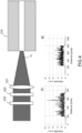
- FIG. 4 thus represents a simplified diagram illustrating elements of a system for generating high peak power laser pulses according to the present description with a spatial shaping module comprising a polarization jammer 232, as described for example with reference to the Fig.3 .
- the applicant has shown that if the electric field incident on the DOE 220 is at least partially depolarized, this will have the effect of reducing the contrast of the speckle.
- a completely spatially depolarized field can be decomposed into two orthogonal polarization states which cannot interfere with each other. Each of the polarization states will generate a speckle pattern that is not spatially correlated with the other polarization state.
- the pulse field I F in the Fourier plane of the optical system 221 used for shaping can be written: E ⁇ Out u v ⁇ E 0 x y t ⁇ t x y + e j ⁇ Diff x y . e ⁇ j 2 ⁇ xu + yv dx dy 1 2 e 1 ⁇ + 1 2 e 2 ⁇
- the speckle contrast is reduced by a factor 2 compared to the speckle contrast without shaping (diagram 41, Fig. 4 ).
- a liquid crystal depolarizer can be configured to present a phase shift with an expression similar to that resulting from a Cornu type depolarizer.
- Such liquid crystal depolarizers are for example described in US9599834 [Ref. 6] and comprise a thin film of liquid crystal polymer sandwiched for example between two glass plates, for example N-BK7.
- the double prism depolarizer (composed of quartz and silica respectively) is similar to the Cornu depolarizer; however, the angle between the two prisms is much smaller (typically 2°) and only the first prism is birefringent.
- the second prism is made of fused silica, which has a refractive index very similar to quartz.
- the fast axis of the quartz prism is generally 45° from the corner.
- the entire component is more compact than a Cornu depolarizer (for the same aperture).
- the polarization is periodic. Because the angle of the prisms is much smaller than in a Cornu depolarizer, the spatial depolarization period is greater.
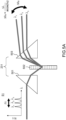
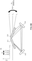
- FIG. 5A represents a simplified diagram illustrating another example of a spatial shaping module for the spatial shaping of pulses in a system according to the present description.
- the spatial shaping module 231 comprises a dispersive element 502, for example a network.
- the network is arranged in this example between two prisms 501, 503 (which could be replaced by mirrors); the prisms are configured to deflect the incident beams such that they arrive on the grating with a desired angle of incidence, for example an angle of incidence making it possible to maximize the diffraction efficiency of the grating.
- a network spatial shaping module as described in the Fig. 5A allows the shaping of initial laser pulses whose electric field comprises a plurality of spectral lines.
- the laser source 241 is a longitudinal multimode laser source, for example an Nd:YAG laser of the non-injected q-switch type.
- the network makes it possible to spatially decorrelate the N spectral lines of the laser.
- the use of a diffraction grating makes it possible to reduce the contrast of the speckle present in the shaping of a laser beam by means of a diffractive optical element.
- the parameter ⁇ ⁇ 2 ⁇ vs 2 L , is linked to the free spectral interval of the laser cavity used.
- ⁇ n is a random phase term associated with each of the spectral components.
- ⁇ d , ⁇ 0 , and m are respectively the angle of diffraction by the grating, the angle of incidence, and the order of diffraction of the grating.
- E ⁇ E 0 x y t ⁇ 0 NOT 1 NOT e j ⁇ 0 + not ⁇ ⁇ t ⁇ k not ⁇ . r ⁇ + ⁇ not + CC e 1 ⁇
- the intensity figure in the Fourier plane therefore corresponds to a sum of diffraction figures spatially shifted in the direction u, each spectral component being composed of the same deterministic part and the same random part.
- Each diffraction pattern corresponding to n longitudinal mode is offset by the distance F. tan ⁇ n from the diffraction patterns corresponding to the longitudinal modes adjacent to it. If the N spectral lines of the laser respect the condition. tan ⁇ ⁇ d > ⁇ D , then the intensity profile will be composed of a sum of noisy profiles that are not correlated with each other. The observed speckle contrast will thus be reduced by a factor NOT .
- the shaping module includes a single network.
- Fig. 5B represents a simplified diagram illustrating a spatial shaping module with a first network 511 and a second network 512, for the spatial shaping of pulses in a system according to the present description.
- two mirrors 513, 514 are configured to route the beams with an angle of incidence on each of the networks which maximizes their respective efficiency.
- Using two networks instead of just one ( Fig. 5A ) allows the angular dispersion to be doubled.
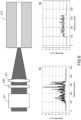
- FIG. 6 represents a simplified diagram illustrating elements of a system for generating high peak power laser pulses according to the present description with a spatial shaping module 231 comprising one or more networks, as described for example with reference to the Fig.5A or to the Fig. 5B .
- Figure 61 illustrates a “top hat” intensity profile at the input of the multimode fiber 210, without a shaping module.
- the speckle contrast is in this example equal to 0.72.
- Figure 62 illustrates a “top hat” intensity profile at the input of the multimode fiber 210, with a network shaping module as illustrated for example on the Fig. 5A .
- the grating in this example includes a pitch of 575 nm and is optimized for a wavelength of 1064 nm with a LITTROW incident angle of 67.7°.
- the spatial shaping module thus produced makes it possible to reduce the initial contrast by a factor of 2.5.
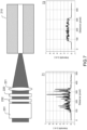
- the shaping module can include both a polarization jammer 232 and a network device 231, as described in the Fig. 7 .
Landscapes
- Physics & Mathematics (AREA)
- General Physics & Mathematics (AREA)
- Optics & Photonics (AREA)
- Lasers (AREA)
- Polarising Elements (AREA)
- Diffracting Gratings Or Hologram Optical Elements (AREA)
Claims (9)
- System (200) zur Erzeugung von Laserimpulsen mit hoher Spitzenleistung, aufweisend:- eine Lichtquelle (240) zur Emission von anfänglichen Nanosekunden-Laserimpulsen (IL);- eine Faservorrichtung für den Transport von Laserimpulsen, die mindestens eine erste Multimodefaser (210) mit einem einzelnen Kern (212) aufweist;- ein diffraktives optisches Element (220) und ein optisches System (221), die vor der Faservorrichtung angeordnet und konfiguriert sind, um ausgehend von jedem der anfänglichen Laserimpulse einen Laserimpuls (IF) am Eingang der Faservorrichtung zu erzeugen, wobei die räumliche Intensitätsverteilung jedes der Laserimpulse (IF) auf einer Eingangsseite der ersten Multimodefaser eine räumliche Niederfrequenzkomponente vom Typ "Top Hat" aufweist, die mit einer räumlichen Hochfrequenzkomponente summiert ist, die aus Interferenzen vom Typ Speckle resultiert;- ein räumliches Formgebungsmodul (230), das vor der Faservorrichtung angeordnet ist und konfiguriert ist, um ein erstes elektrisches Feld in ein zweites elektrisches Feld zu transformieren, das aus einer Summe von N Komponenten gebildet wird, die zumindest teilweise räumlich inkohärent zueinander sind, N ≥ 2, so dass der Kontrast der aus den Interferenzen vom Typ Speckle resultierenden räumlichen Hochfrequenzkomponente im Vergleich zu einem ursprünglichen Kontrast, der ohne räumliches Formgebungsmodul definiert ist, reduziert wird.
- System zur Erzeugung von Laserimpulsen nach Anspruch 1, wobei das räumliche Formungsmodul (230) vor dem optischen System (221) angeordnet ist.
- System zur Erzeugung von Laserimpulsen nach einem der vorhergehenden Ansprüche, wobei das räumliche Formgebungsmodul (230) einen Polarisationsstörer (232) aufweist, der so konfiguriert ist, dass er ein erstes elektrisches Feld in ein zweites elektrisches Feld transformiert, das aus einer Summe von zwei Komponenten entlang zweier orthogonaler Achsen gebildet wird, wobei die beiden Komponenten eine variable Phasenverschiebung entlang einer gegebenen Achse (y) aufweisen.
- System zur Erzeugung von Laserimpulsen nach Anspruch 3, wobei:- die variable Phasenverschiebung entlang der Achse (y) periodisch ist, was zu einer periodischen Änderung eines Polarisationszustands des elektrischen Feldes am Ausgang des Polarisationsstörers führt; und- der Polarisationsstörer (232) so angeordnet ist, dass eine räumliche Intensitätsverteilung des ersten elektrischen Feldes entlang der Achse (y) eine Dimension aufweist, die größer ist als eine Periode der Variation des Polarisationszustandes.
- System (200) zur Erzeugung von Laserimpulsen nach einem der vorhergehenden Ansprüche, wobei:- die Quelle ein longitudinaler Multimode ist; und- das räumliche Formgebungsmodul mindestens ein erstes Beugungsgitter (231) aufweist, das konfiguriert ist, um ein erstes elektrisches Feld in ein zweites elektrisches Feld zu transformieren, das aus einer Summe von N Komponenten, N ≥ 2, gebildet wird, wobei die N Komponenten durch nicht-kolineare Wellenvektoren gekennzeichnet sind.
- System zur Erzeugung von Laserimpulsen nach Anspruch 5, wobei N im Bereich von 2 bis 10 liegt.
- System zur Erzeugung von Laserimpulsen nach einem der Ansprüche 5 oder 6, wobei das räumliche Formgebungsmodul mindestens ein zweites Gitter aufweist, das im Anschluss an das erste Gitter angeordnet ist.
- System zur Erzeugung von Laserimpulsen nach einem der Ansprüche 5 bis 7, wobei das räumliche Formgebungsmodul zusätzlich einen Polarisationsstörer aufweist, wobei das mindestens eine erste Gitter vor dem Polarisationsstörer angeordnet ist.
- Verfahren zur Erzeugung von Laserimpulsen mit hoher Spitzenleistung, die folgenden Schritte aufweisend:- Aussenden von anfänglichen Nanosekunden- Laserimpulsen (IL) mittels einer Lichtquelle (240);- Erzeugen, mittels eines diffraktiven optischen Elements (220) und eines optischen Systems (221), aus jedem der anfänglichen Laserimpulse einen Laserimpuls (IF), wobei die räumliche Intensitätsverteilung jedes der Laserimpulse (IF) in einer Fourierebene des optischen Systems (221) eine niederfrequente räumliche "Top Hat"-Komponente aufweist, die mit einer hochfrequenten räumlichen Komponente summiert wird, die aus Interferenzen vom Typ Speckle resultiert;- Transportieren der Laserimpulse (IF) mittels einer Faservorrichtung, die eine Multimodefaser (210) mit einem einzelnen Kern (212) aufweist, wobei eine Eingangsseite der Multimodefaser (210) im Wesentlichen mit der Fourierebene des optischen Systems (221) zusammenfällt;- räumliches Formen der ursprünglichen Laserimpulse mittels eines räumlichen Formungsmoduls (230), das vor der Faservorrichtung angeordnet und so konfiguriert ist, dass es ein erstes elektrisches Feld in ein zweites elektrisches Feld transformiert, das aus einer Summe einer Vielzahl von N Komponenten gebildet wird, wobei N ≥ 2, wobei die N Komponenten zumindest teilweise räumlich inkohärent zueinander sind, so dass der Kontrast der räumlichen Hochfrequenzkomponente, der sich aus Interferenz vom Typ Speckle auf der Eingangsseite der ersten Multimodefaser ergibt, im Vergleich zu einem ursprünglichen Kontrast, der ohne ein räumliches Formungsmodul definiert ist, reduziert wird.
Applications Claiming Priority (2)
| Application Number | Priority Date | Filing Date | Title |
|---|---|---|---|
| FR2008512A FR3113428B1 (fr) | 2020-08-14 | 2020-08-14 | Procédés et systèmes pour la génération d’impulsions laser de forte puissance crête |
| PCT/EP2021/072100 WO2022033995A1 (fr) | 2020-08-14 | 2021-08-06 | Procédés et systèmes pour la génération d'impulsions laser de forte puissance crête |
Publications (2)
| Publication Number | Publication Date |
|---|---|
| EP4196844A1 EP4196844A1 (de) | 2023-06-21 |
| EP4196844B1 true EP4196844B1 (de) | 2024-08-07 |
Family
ID=74095861
Family Applications (1)
| Application Number | Title | Priority Date | Filing Date |
|---|---|---|---|
| EP21762001.2A Active EP4196844B1 (de) | 2020-08-14 | 2021-08-06 | Methoden und systeme zur erzeugung von laserpulsen hoher spitzenleistung |
Country Status (6)
| Country | Link |
|---|---|
| US (1) | US20230314823A1 (de) |
| EP (1) | EP4196844B1 (de) |
| JP (1) | JP2023538029A (de) |
| CN (1) | CN116348805A (de) |
| FR (1) | FR3113428B1 (de) |
| WO (1) | WO2022033995A1 (de) |
Families Citing this family (1)
| Publication number | Priority date | Publication date | Assignee | Title |
|---|---|---|---|---|
| CN116590517A (zh) * | 2023-03-30 | 2023-08-15 | 江苏大学 | 一种可移动激光冲击复合超声冲击装置及方法 |
Family Cites Families (23)
| Publication number | Priority date | Publication date | Assignee | Title |
|---|---|---|---|---|
| US6002102A (en) | 1997-02-25 | 1999-12-14 | Lsp Technologies, Inc. | Hidden surface laser shock processing |
| RU2343516C2 (ru) * | 2001-07-16 | 2009-01-10 | Ой Модинес Лтд | Дифракционное профилирование распределения интенсивности частично пространственно когерентного светового пучка |
| US6818854B2 (en) | 2001-09-14 | 2004-11-16 | The Regents Of The University Of California | Laser peening with fiber optic delivery |
| JP4123860B2 (ja) * | 2002-08-05 | 2008-07-23 | 横河電機株式会社 | 偏光解消板並びに分光器及びポリクロメータ |
| JP3807374B2 (ja) * | 2003-01-31 | 2006-08-09 | 住友電気工業株式会社 | 一括多点ホモジナイズ光学系 |
| JP2005084266A (ja) * | 2003-09-05 | 2005-03-31 | Kawasaki Heavy Ind Ltd | 光制御装置および光制御方法 |
| ATE498928T1 (de) | 2003-10-30 | 2011-03-15 | Metal Improvement Company Llc | Relay teleskop, laserverstärker, und laserschockbestrahlungsverfahren und dessen vorrichtung |
| JP2006003479A (ja) * | 2004-06-16 | 2006-01-05 | Nikon Corp | 光学素子及び照明光学系 |
| JP5029036B2 (ja) * | 2007-01-25 | 2012-09-19 | 住友電気工業株式会社 | 光源装置およびスペクトル分析装置 |
| KR20100009943A (ko) * | 2008-07-21 | 2010-01-29 | 삼성전기주식회사 | 레이저 광원을 이용한 스캐닝 디스플레이 장치 |
| JP5617253B2 (ja) * | 2010-01-21 | 2014-11-05 | 横浜ゴム株式会社 | 変性粉砕加硫ゴムの製造法 |
| JP5914329B2 (ja) * | 2010-05-24 | 2016-05-11 | ギガフォトン株式会社 | 固体レーザ装置およびレーザシステム |
| CN102053372B (zh) * | 2011-01-27 | 2012-05-30 | 清华大学 | 一种改进的光束匀化装置的研制 |
| JP5949900B2 (ja) * | 2012-03-19 | 2016-07-13 | 富士通株式会社 | 偏光度低減装置、光源装置、光増幅装置およびラマン増幅用励起光源装置 |
| US9124066B2 (en) * | 2012-05-02 | 2015-09-01 | Lawrence Livermore National Security, Llc | Diffractive optical elements for transformation of modes in lasers |
| CN104808343B (zh) * | 2014-01-29 | 2018-03-30 | 上海微电子装备(集团)股份有限公司 | 一种激光退火匀光装置 |
| WO2016040890A1 (en) | 2014-09-12 | 2016-03-17 | Thorlabs, Inc. | Depolarizers and methods of making thereof |
| EP3165872B1 (de) * | 2015-11-04 | 2020-04-15 | Hexagon Technology Center GmbH | Kompensation der lichtintensität entlang einer lichtlinie, die eine bessere messqualität sichert |
| GB201713740D0 (en) * | 2017-08-25 | 2017-10-11 | Nkt Photonics As | Depolarizing homogenizer |
| DE102017217145A1 (de) * | 2017-09-27 | 2019-03-28 | Trumpf Laser Gmbh | Lasersystem und Verfahren zur Erzeugung eines Top-Hat- angenäherten Strahlprofils |
| FR3081737B1 (fr) | 2018-06-05 | 2022-02-11 | Imagine Optic | Procedes et systemes pour la generation d'impulsions laser de forte puissance crete |
| FR3081738B1 (fr) | 2018-06-05 | 2020-09-04 | Imagine Optic | Procedes et systemes pour la generation d'impulsions laser de forte puissance crete |
| US11378724B2 (en) * | 2018-12-23 | 2022-07-05 | Ii-Vi Delaware, Inc. | Diffraction grating array for wide-angle illuminateon |
-
2020
- 2020-08-14 FR FR2008512A patent/FR3113428B1/fr active Active
-
2021
- 2021-08-06 WO PCT/EP2021/072100 patent/WO2022033995A1/fr not_active Ceased
- 2021-08-06 EP EP21762001.2A patent/EP4196844B1/de active Active
- 2021-08-06 CN CN202180070386.1A patent/CN116348805A/zh active Pending
- 2021-08-06 US US18/041,143 patent/US20230314823A1/en active Pending
- 2021-08-06 JP JP2023511584A patent/JP2023538029A/ja active Pending
Also Published As
| Publication number | Publication date |
|---|---|
| WO2022033995A1 (fr) | 2022-02-17 |
| FR3113428B1 (fr) | 2022-08-19 |
| FR3113428A1 (fr) | 2022-02-18 |
| EP4196844A1 (de) | 2023-06-21 |
| JP2023538029A (ja) | 2023-09-06 |
| CN116348805A (zh) | 2023-06-27 |
| US20230314823A1 (en) | 2023-10-05 |
Similar Documents
| Publication | Publication Date | Title |
|---|---|---|
| EP3804050B1 (de) | Verfahren und systeme zur erzeugung von laserimpulsen mit hoher spitzenleistung | |
| FR3081737A1 (fr) | Procedes et systemes pour la generation d'impulsions laser de forte puissance crete | |
| EP0500882B1 (de) | Laser mit gekoppelten optischen wellenleitern | |
| FR3087276A1 (fr) | Systeme et procede de compression d'impulsions lumineuses breves ou ultrabreves et systeme laser a impulsions lumineuses associe | |
| CN115769139A (zh) | 用于激光脉冲的频谱展宽的设备以及激光系统 | |
| EP0847115B1 (de) | Lichtverstärkervorrichtung mit zwei einfallenden Bündeln | |
| EP2147487B1 (de) | Gepulster microchip-laser | |
| FR2934722A1 (fr) | Dispositif de generation d'une impulsion laser a duree reduite. | |
| WO2022033995A1 (fr) | Procédés et systèmes pour la génération d'impulsions laser de forte puissance crête | |
| EP2082290A1 (de) | Verfahren zur einstellung der pupillenverzögerungskompensation eines konvergenten oder divergenten strahls | |
| WO2021152245A1 (fr) | Dispositif de traitement d'un faisceau lumineux par l'intermediaire d'un convertisseur multi plan pour le conformer à une forme prédéterminée | |
| FR2771519A1 (fr) | Moyens pour la generation de rayonnements optiques accordables au moins en frequence | |
| FR3047118A1 (fr) | Dispositif de generation d’un faisceau de photons polychromatique et spatialement autoadapte | |
| FR3047119A1 (fr) | Dispositif de generation d’un faisceau de photons polychromatique et d’energie sensiblement constante | |
| FR2884623A1 (fr) | Dispositif de generation d'une lumiere polychromatique a spectre continu par excitation a une longueur d'onde | |
| FR3137221A1 (fr) | Système et procédé de compression d’impulsions lumineuses | |
| FR2929766A1 (fr) | Procede de pompage d'un laser bifrequence, dispositif de pompage associe et laser bifrequence incorporant un tel dispositif de pompage | |
| EP0932057B1 (de) | Lichtwellen diffraktierende Vorrichtung | |
| WO2012052446A1 (fr) | Source laser nanoseconde | |
| Cheng et al. | Near-field flat focusing mirrors using a metallic subwavelength grating on top of a plasmonic waveguide | |
| EP0767519A1 (de) | Vorrichtung zur optischen Verstärkung | |
| Boreman et al. | (HEL MRI) 3D Meta-Optics for High Energy Lasers |
Legal Events
| Date | Code | Title | Description |
|---|---|---|---|
| STAA | Information on the status of an ep patent application or granted ep patent |
Free format text: STATUS: UNKNOWN |
|
| STAA | Information on the status of an ep patent application or granted ep patent |
Free format text: STATUS: THE INTERNATIONAL PUBLICATION HAS BEEN MADE |
|
| PUAI | Public reference made under article 153(3) epc to a published international application that has entered the european phase |
Free format text: ORIGINAL CODE: 0009012 |
|
| STAA | Information on the status of an ep patent application or granted ep patent |
Free format text: STATUS: REQUEST FOR EXAMINATION WAS MADE |
|
| 17P | Request for examination filed |
Effective date: 20230306 |
|
| AK | Designated contracting states |
Kind code of ref document: A1 Designated state(s): AL AT BE BG CH CY CZ DE DK EE ES FI FR GB GR HR HU IE IS IT LI LT LU LV MC MK MT NL NO PL PT RO RS SE SI SK SM TR |
|
| DAV | Request for validation of the european patent (deleted) | ||
| DAX | Request for extension of the european patent (deleted) | ||
| GRAP | Despatch of communication of intention to grant a patent |
Free format text: ORIGINAL CODE: EPIDOSNIGR1 |
|
| STAA | Information on the status of an ep patent application or granted ep patent |
Free format text: STATUS: GRANT OF PATENT IS INTENDED |
|
| INTG | Intention to grant announced |
Effective date: 20240314 |
|
| GRAS | Grant fee paid |
Free format text: ORIGINAL CODE: EPIDOSNIGR3 |
|
| GRAA | (expected) grant |
Free format text: ORIGINAL CODE: 0009210 |
|
| STAA | Information on the status of an ep patent application or granted ep patent |
Free format text: STATUS: THE PATENT HAS BEEN GRANTED |
|
| AK | Designated contracting states |
Kind code of ref document: B1 Designated state(s): AL AT BE BG CH CY CZ DE DK EE ES FI FR GB GR HR HU IE IS IT LI LT LU LV MC MK MT NL NO PL PT RO RS SE SI SK SM TR |
|
| REG | Reference to a national code |
Ref country code: GB Ref legal event code: FG4D Free format text: NOT ENGLISH |
|
| REG | Reference to a national code |
Ref country code: CH Ref legal event code: EP |
|
| REG | Reference to a national code |
Ref country code: IE Ref legal event code: FG4D Free format text: LANGUAGE OF EP DOCUMENT: FRENCH |
|
| REG | Reference to a national code |
Ref country code: DE Ref legal event code: R096 Ref document number: 602021016933 Country of ref document: DE |
|
| REG | Reference to a national code |
Ref country code: LT Ref legal event code: MG9D |
|
| REG | Reference to a national code |
Ref country code: NL Ref legal event code: MP Effective date: 20240807 |
|
| PG25 | Lapsed in a contracting state [announced via postgrant information from national office to epo] |
Ref country code: NO Free format text: LAPSE BECAUSE OF FAILURE TO SUBMIT A TRANSLATION OF THE DESCRIPTION OR TO PAY THE FEE WITHIN THE PRESCRIBED TIME-LIMIT Effective date: 20241107 |
|
| REG | Reference to a national code |
Ref country code: AT Ref legal event code: MK05 Ref document number: 1711591 Country of ref document: AT Kind code of ref document: T Effective date: 20240807 |
|
| PG25 | Lapsed in a contracting state [announced via postgrant information from national office to epo] |
Ref country code: GR Free format text: LAPSE BECAUSE OF FAILURE TO SUBMIT A TRANSLATION OF THE DESCRIPTION OR TO PAY THE FEE WITHIN THE PRESCRIBED TIME-LIMIT Effective date: 20241108 Ref country code: NL Free format text: LAPSE BECAUSE OF FAILURE TO SUBMIT A TRANSLATION OF THE DESCRIPTION OR TO PAY THE FEE WITHIN THE PRESCRIBED TIME-LIMIT Effective date: 20240807 Ref country code: PL Free format text: LAPSE BECAUSE OF FAILURE TO SUBMIT A TRANSLATION OF THE DESCRIPTION OR TO PAY THE FEE WITHIN THE PRESCRIBED TIME-LIMIT Effective date: 20240807 Ref country code: FI Free format text: LAPSE BECAUSE OF FAILURE TO SUBMIT A TRANSLATION OF THE DESCRIPTION OR TO PAY THE FEE WITHIN THE PRESCRIBED TIME-LIMIT Effective date: 20240807 Ref country code: PT Free format text: LAPSE BECAUSE OF FAILURE TO SUBMIT A TRANSLATION OF THE DESCRIPTION OR TO PAY THE FEE WITHIN THE PRESCRIBED TIME-LIMIT Effective date: 20241209 |
|
| PG25 | Lapsed in a contracting state [announced via postgrant information from national office to epo] |
Ref country code: BG Free format text: LAPSE BECAUSE OF FAILURE TO SUBMIT A TRANSLATION OF THE DESCRIPTION OR TO PAY THE FEE WITHIN THE PRESCRIBED TIME-LIMIT Effective date: 20240807 |
|
| PG25 | Lapsed in a contracting state [announced via postgrant information from national office to epo] |
Ref country code: LV Free format text: LAPSE BECAUSE OF FAILURE TO SUBMIT A TRANSLATION OF THE DESCRIPTION OR TO PAY THE FEE WITHIN THE PRESCRIBED TIME-LIMIT Effective date: 20240807 |
|
| PG25 | Lapsed in a contracting state [announced via postgrant information from national office to epo] |
Ref country code: AT Free format text: LAPSE BECAUSE OF FAILURE TO SUBMIT A TRANSLATION OF THE DESCRIPTION OR TO PAY THE FEE WITHIN THE PRESCRIBED TIME-LIMIT Effective date: 20240807 Ref country code: IS Free format text: LAPSE BECAUSE OF FAILURE TO SUBMIT A TRANSLATION OF THE DESCRIPTION OR TO PAY THE FEE WITHIN THE PRESCRIBED TIME-LIMIT Effective date: 20241207 |
|
| PG25 | Lapsed in a contracting state [announced via postgrant information from national office to epo] |
Ref country code: HR Free format text: LAPSE BECAUSE OF FAILURE TO SUBMIT A TRANSLATION OF THE DESCRIPTION OR TO PAY THE FEE WITHIN THE PRESCRIBED TIME-LIMIT Effective date: 20240807 |
|
| PG25 | Lapsed in a contracting state [announced via postgrant information from national office to epo] |
Ref country code: RS Free format text: LAPSE BECAUSE OF FAILURE TO SUBMIT A TRANSLATION OF THE DESCRIPTION OR TO PAY THE FEE WITHIN THE PRESCRIBED TIME-LIMIT Effective date: 20241107 Ref country code: ES Free format text: LAPSE BECAUSE OF FAILURE TO SUBMIT A TRANSLATION OF THE DESCRIPTION OR TO PAY THE FEE WITHIN THE PRESCRIBED TIME-LIMIT Effective date: 20240807 |
|
| PG25 | Lapsed in a contracting state [announced via postgrant information from national office to epo] |
Ref country code: RS Free format text: LAPSE BECAUSE OF FAILURE TO SUBMIT A TRANSLATION OF THE DESCRIPTION OR TO PAY THE FEE WITHIN THE PRESCRIBED TIME-LIMIT Effective date: 20241107 Ref country code: PT Free format text: LAPSE BECAUSE OF FAILURE TO SUBMIT A TRANSLATION OF THE DESCRIPTION OR TO PAY THE FEE WITHIN THE PRESCRIBED TIME-LIMIT Effective date: 20241209 Ref country code: PL Free format text: LAPSE BECAUSE OF FAILURE TO SUBMIT A TRANSLATION OF THE DESCRIPTION OR TO PAY THE FEE WITHIN THE PRESCRIBED TIME-LIMIT Effective date: 20240807 Ref country code: NO Free format text: LAPSE BECAUSE OF FAILURE TO SUBMIT A TRANSLATION OF THE DESCRIPTION OR TO PAY THE FEE WITHIN THE PRESCRIBED TIME-LIMIT Effective date: 20241107 Ref country code: NL Free format text: LAPSE BECAUSE OF FAILURE TO SUBMIT A TRANSLATION OF THE DESCRIPTION OR TO PAY THE FEE WITHIN THE PRESCRIBED TIME-LIMIT Effective date: 20240807 Ref country code: LV Free format text: LAPSE BECAUSE OF FAILURE TO SUBMIT A TRANSLATION OF THE DESCRIPTION OR TO PAY THE FEE WITHIN THE PRESCRIBED TIME-LIMIT Effective date: 20240807 Ref country code: IS Free format text: LAPSE BECAUSE OF FAILURE TO SUBMIT A TRANSLATION OF THE DESCRIPTION OR TO PAY THE FEE WITHIN THE PRESCRIBED TIME-LIMIT Effective date: 20241207 Ref country code: HR Free format text: LAPSE BECAUSE OF FAILURE TO SUBMIT A TRANSLATION OF THE DESCRIPTION OR TO PAY THE FEE WITHIN THE PRESCRIBED TIME-LIMIT Effective date: 20240807 Ref country code: GR Free format text: LAPSE BECAUSE OF FAILURE TO SUBMIT A TRANSLATION OF THE DESCRIPTION OR TO PAY THE FEE WITHIN THE PRESCRIBED TIME-LIMIT Effective date: 20241108 Ref country code: FI Free format text: LAPSE BECAUSE OF FAILURE TO SUBMIT A TRANSLATION OF THE DESCRIPTION OR TO PAY THE FEE WITHIN THE PRESCRIBED TIME-LIMIT Effective date: 20240807 Ref country code: ES Free format text: LAPSE BECAUSE OF FAILURE TO SUBMIT A TRANSLATION OF THE DESCRIPTION OR TO PAY THE FEE WITHIN THE PRESCRIBED TIME-LIMIT Effective date: 20240807 Ref country code: BG Free format text: LAPSE BECAUSE OF FAILURE TO SUBMIT A TRANSLATION OF THE DESCRIPTION OR TO PAY THE FEE WITHIN THE PRESCRIBED TIME-LIMIT Effective date: 20240807 Ref country code: AT Free format text: LAPSE BECAUSE OF FAILURE TO SUBMIT A TRANSLATION OF THE DESCRIPTION OR TO PAY THE FEE WITHIN THE PRESCRIBED TIME-LIMIT Effective date: 20240807 |
|
| PG25 | Lapsed in a contracting state [announced via postgrant information from national office to epo] |
Ref country code: SM Free format text: LAPSE BECAUSE OF FAILURE TO SUBMIT A TRANSLATION OF THE DESCRIPTION OR TO PAY THE FEE WITHIN THE PRESCRIBED TIME-LIMIT Effective date: 20240807 Ref country code: DK Free format text: LAPSE BECAUSE OF FAILURE TO SUBMIT A TRANSLATION OF THE DESCRIPTION OR TO PAY THE FEE WITHIN THE PRESCRIBED TIME-LIMIT Effective date: 20240807 |
|
| PG25 | Lapsed in a contracting state [announced via postgrant information from national office to epo] |
Ref country code: EE Free format text: LAPSE BECAUSE OF FAILURE TO SUBMIT A TRANSLATION OF THE DESCRIPTION OR TO PAY THE FEE WITHIN THE PRESCRIBED TIME-LIMIT Effective date: 20240807 |
|
| PG25 | Lapsed in a contracting state [announced via postgrant information from national office to epo] |
Ref country code: CZ Free format text: LAPSE BECAUSE OF FAILURE TO SUBMIT A TRANSLATION OF THE DESCRIPTION OR TO PAY THE FEE WITHIN THE PRESCRIBED TIME-LIMIT Effective date: 20240807 |
|
| PG25 | Lapsed in a contracting state [announced via postgrant information from national office to epo] |
Ref country code: SK Free format text: LAPSE BECAUSE OF FAILURE TO SUBMIT A TRANSLATION OF THE DESCRIPTION OR TO PAY THE FEE WITHIN THE PRESCRIBED TIME-LIMIT Effective date: 20240807 |
|
| REG | Reference to a national code |
Ref country code: DE Ref legal event code: R097 Ref document number: 602021016933 Country of ref document: DE |
|
| PLBE | No opposition filed within time limit |
Free format text: ORIGINAL CODE: 0009261 |
|
| STAA | Information on the status of an ep patent application or granted ep patent |
Free format text: STATUS: NO OPPOSITION FILED WITHIN TIME LIMIT |
|
| 26N | No opposition filed |
Effective date: 20250508 |
|
| PG25 | Lapsed in a contracting state [announced via postgrant information from national office to epo] |
Ref country code: SE Free format text: LAPSE BECAUSE OF FAILURE TO SUBMIT A TRANSLATION OF THE DESCRIPTION OR TO PAY THE FEE WITHIN THE PRESCRIBED TIME-LIMIT Effective date: 20240807 |
|
| PGFP | Annual fee paid to national office [announced via postgrant information from national office to epo] |
Ref country code: DE Payment date: 20250708 Year of fee payment: 5 |
|
| PGFP | Annual fee paid to national office [announced via postgrant information from national office to epo] |
Ref country code: GB Payment date: 20250710 Year of fee payment: 5 |
|
| PGFP | Annual fee paid to national office [announced via postgrant information from national office to epo] |
Ref country code: FR Payment date: 20250708 Year of fee payment: 5 |
|
| PG25 | Lapsed in a contracting state [announced via postgrant information from national office to epo] |
Ref country code: IT Free format text: LAPSE BECAUSE OF FAILURE TO SUBMIT A TRANSLATION OF THE DESCRIPTION OR TO PAY THE FEE WITHIN THE PRESCRIBED TIME-LIMIT Effective date: 20240807 |
|
| REG | Reference to a national code |
Ref country code: CH Ref legal event code: H13 Free format text: ST27 STATUS EVENT CODE: U-0-0-H10-H13 (AS PROVIDED BY THE NATIONAL OFFICE) Effective date: 20260324 |
|
| PG25 | Lapsed in a contracting state [announced via postgrant information from national office to epo] |
Ref country code: MC Free format text: LAPSE BECAUSE OF FAILURE TO SUBMIT A TRANSLATION OF THE DESCRIPTION OR TO PAY THE FEE WITHIN THE PRESCRIBED TIME-LIMIT Effective date: 20240807 |
|
| PG25 | Lapsed in a contracting state [announced via postgrant information from national office to epo] |
Ref country code: RO Free format text: LAPSE BECAUSE OF FAILURE TO SUBMIT A TRANSLATION OF THE DESCRIPTION OR TO PAY THE FEE WITHIN THE PRESCRIBED TIME-LIMIT Effective date: 20240807 Ref country code: LU Free format text: LAPSE BECAUSE OF NON-PAYMENT OF DUE FEES Effective date: 20250806 |
|
| PG25 | Lapsed in a contracting state [announced via postgrant information from national office to epo] |
Ref country code: CH Free format text: LAPSE BECAUSE OF NON-PAYMENT OF DUE FEES Effective date: 20250831 |
|
| REG | Reference to a national code |
Ref country code: BE Ref legal event code: MM Effective date: 20250831 |
|
| PG25 | Lapsed in a contracting state [announced via postgrant information from national office to epo] |
Ref country code: LT Free format text: LAPSE BECAUSE OF FAILURE TO SUBMIT A TRANSLATION OF THE DESCRIPTION OR TO PAY THE FEE WITHIN THE PRESCRIBED TIME-LIMIT Effective date: 20240807 |
|
| PG25 | Lapsed in a contracting state [announced via postgrant information from national office to epo] |
Ref country code: BE Free format text: LAPSE BECAUSE OF NON-PAYMENT OF DUE FEES Effective date: 20250831 Ref country code: IE Free format text: LAPSE BECAUSE OF NON-PAYMENT OF DUE FEES Effective date: 20250806 |