EP4196403B1 - Non-refillable dosing capillary insert - Google Patents
Non-refillable dosing capillary insert Download PDFInfo
- Publication number
- EP4196403B1 EP4196403B1 EP20757327.0A EP20757327A EP4196403B1 EP 4196403 B1 EP4196403 B1 EP 4196403B1 EP 20757327 A EP20757327 A EP 20757327A EP 4196403 B1 EP4196403 B1 EP 4196403B1
- Authority
- EP
- European Patent Office
- Prior art keywords
- insert
- bio
- cone
- capillary insert
- capillary
- Prior art date
- Legal status (The legal status is an assumption and is not a legal conclusion. Google has not performed a legal analysis and makes no representation as to the accuracy of the status listed.)
- Active
Links
Images


Classifications
-
- B—PERFORMING OPERATIONS; TRANSPORTING
- B65—CONVEYING; PACKING; STORING; HANDLING THIN OR FILAMENTARY MATERIAL
- B65D—CONTAINERS FOR STORAGE OR TRANSPORT OF ARTICLES OR MATERIALS, e.g. BAGS, BARRELS, BOTTLES, BOXES, CANS, CARTONS, CRATES, DRUMS, JARS, TANKS, HOPPERS, FORWARDING CONTAINERS; ACCESSORIES, CLOSURES, OR FITTINGS THEREFOR; PACKAGING ELEMENTS; PACKAGES
- B65D49/00—Arrangements or devices for preventing refilling of containers
- B65D49/12—Arrangements or devices for preventing refilling of containers by destroying, in the act of opening the container, an integral portion thereof
-
- B—PERFORMING OPERATIONS; TRANSPORTING
- B65—CONVEYING; PACKING; STORING; HANDLING THIN OR FILAMENTARY MATERIAL
- B65D—CONTAINERS FOR STORAGE OR TRANSPORT OF ARTICLES OR MATERIALS, e.g. BAGS, BARRELS, BOTTLES, BOXES, CANS, CARTONS, CRATES, DRUMS, JARS, TANKS, HOPPERS, FORWARDING CONTAINERS; ACCESSORIES, CLOSURES, OR FITTINGS THEREFOR; PACKAGING ELEMENTS; PACKAGES
- B65D47/00—Closures with filling and discharging, or with discharging, devices
- B65D47/04—Closures with discharging devices other than pumps
- B65D47/06—Closures with discharging devices other than pumps with pouring spouts or tubes; with discharge nozzles or passages
- B65D47/18—Closures with discharging devices other than pumps with pouring spouts or tubes; with discharge nozzles or passages for discharging drops; Droppers
Definitions
- the present invention relates to the field of pharmaceutical containers and packages that allow a controlled dosage of liquid products, for example in individual drops or in a jet. More particularly, the invention relates to a tamper-proof dosing capillary cap or plug, which does not allow for reuse to be installed in the upper section of a container or package for liquid products. And a container that includes said insert or capillary cap, thus guaranteeing that the user does not fill and reuse said container.
- a container is tamper-proof, when it makes it possible to easily identify or detect unauthorized access to protected content; in general, this is carried out through seals, marks, breakable rings or other techniques that show previous manipulation.
- Another need for packages and containers is that they have a design that prevents them from being refilled after their first use or from being reused for another purpose. This mainly in the containers and packages of pharmaceutical and cosmetic products.
- patent publication WO2009002717 presents a container with evidence of tampering.
- This publication does not refer to a dropper, but provides a closure system for a container in which the closure is non-removably attached to the neck of the container.
- the security system in this container consists of tabs not visible from the outside of the closure, in which a person would have to break those seals internally in order to uncouple the closure, which, in any case, is irreversible.
- patent publication WO2013139352 presents a container with a dispensing closure.
- This publication shows that the container of the invention has a system in which, when attempting to release, rotate, or even unhook the dispenser closure of the container, a predetermined rupture link (or even the outer side wall) of the base, breaks at least partially. In other words, the dispenser closure breaks if it is improperly tampered.
- Publication WO2016198967A1 discloses an improved dispensing system comprising a dosing unit that includes a skirt that has a projection or edge at its lower end and a container that includes a surface located on the inside of the shoulder of the container, where the surface retains the dosing unit through interference with said projection or edge of the dosing unit. Through these characteristics the reuse of the container is prevented.
- Another object of the invention are containers of liquid products that incorporate the improved capillary insert.
- Yet another object of the invention is the use of the improved capillary insert in other inserts available in the state of the art.
- the present invention consists of a capillary insert to administer liquid products, for example in the form of drops or a jet, which is installed in the neck of a reservoir or container for the liquid to be administered.
- the main characteristic of the capillary insert of the present invention is that it prevents its reuse and at the same time leaves evidence that it has been manipulated, violated, detached or damaged; and therefore, the insert is unusable since it disables the proper dosage of the product.
- the capillary insert of the present invention prevents its reuse and tampering through one or more break zones located along the insert.
- the present invention provides an improved capillary insert according to claim 1 that prevents reuse of the container as a dropper or multi-dose dispenser.
- the invention also relates to liquid product containers according to claim 9 incorporating the improved capillary insert. Additionally, the invention provides the use of breaking zones in the capillary insert according to claim 7.
- the present invention relates to a capillary insert (100) for administering liquid products, comprising: a cone (110) that extends axially in the opposite direction to form a skirt (120), where the cone (110) has in its part upper a hole (111) for the administration of liquids through an internal channel (112), the cone (110) has a frusto-conical configuration ending in a washer (114) that divides the cone (110) and the skirt (120) , wherein the insert (100) has one or more homogeneous or non-homogeneous breaking zones, as shown in Figures 1 and 2 .
- Said breaking zones when exerting an external force or subjected to an external force, allow the total or partial breaking of the insert, thanks to one or more thin sections of thickness (115) and one or more thick sections of thickness (116), as seen in Figure 4 . Both partial and total breakage make the insert useless and disables the use of the product.
- the external force applied can be manual, or through tools used by the user.
- the one or more breaking zones (130) of the capillary insert (100) are located in the cone (110) or in the skirt (120). Examples of these breaking zones (130) are shown in Figures 3 , 5a, 5b and 5c .
- the one or more thin (115) or thick (116) sections of thickness are visible or not visible.
- the one or more thick sections of thickness (116) are located on the inner or external part of the breaking zone, as shown in Figure 4 .
- the invention refers to not being visible to the user as this depends on the insert manufacturing material, the size of the thick sections of thickness and the configuration of the thin (115) or thick (116) sections of thickness around the perimeter of the capillary insert (100).
- Figure 1 shows the one or more breaking zones in the cone (110) which are located perimeter along the y-axis and/or at any angle between 0 and 360° from the x-axis of the cone (110), at any height of a defined distance h between the top of the cone (110) and the top surface of the washer (114).
- Figure 1 shows the one or more breaking zones in the skirt (120), which are located perimeter along the y-axis and/or at any angle between 0 and 360° from the x-axis of the skirt (120), at any height of a defined distance h 1 between the lower surface of the washer (114) and the base of the skirt (120).
- the capillary insert (100) of the invention is made of resins from renewable and non-renewable sources.
- resins from renewable sources used in the invention are selected from materials from commercially available renewable sources (e.g. ethanol), such as Bio-PE (Bio Polyethylene), Bio-PEAD / Bio-HDPE (High Density Bio Polyethylene), Bio-PEBD / Bio-LDPE (Low Density Bio Polyethylene), Bio-LLDPE (Linear Low Density Bio Polyethylene) and Bio-PP (Bio Polypropylene).
- commercially available renewable sources e.g. ethanol
- Bio-PE Bio Polyethylene
- Bio-PEAD / Bio-HDPE High Density Bio Polyethylene
- Bio-PEBD / Bio-LDPE Low Density Bio Polyethylene
- Bio-LLDPE Linear Low Density Bio Polyethylene
- Bio-PP Bio Polypropylene
- resins from non-renewable sources used in the invention are selected from polyolefins, including: Low-density polyethylene (PEBD or LDPE); high-density polyethylene (PEAD or HDPE); linear low density polyethylene (PELBD or LLDPE); polypropylene (PP); ethylene-propylene rubber (EPR); poly-alpha-olefin.
- PEBD or LDPE Low-density polyethylene
- PEAD or HDPE high-density polyethylene
- PELBD or LLDPE linear low density polyethylene
- PP polypropylene
- EPR ethylene-propylene rubber
- An embodiment of the invention corresponds to the use of the breaking zones (130) of the capillary insert (100) according to claim 7.
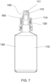
- FIG. 7 Another embodiment of the invention, as shown in Figure 7 , corresponds to a liquid product dispensing container (150) comprising a lid (160); a reservoir (170) for liquid product; a capillary insert (100) arranged at the top of the reservoir (170) and under the lid (160); wherein the capillary insert (100) comprises a cone (110) that extends axially in the opposite direction to form a skirt (120), wherein the cone (110) has in its upper part a hole (111) for the administration of liquids through an internal channel (112), the cone (110) has a frusto-conical configuration ending in a washer (114) that divides the cone (110) and the skirt (120), where the insert (100) has one or more homogeneous or non-homogeneous breaking zones, which when exerting an external force or subjected to an external force allow the total or partial breaking of the insert.
- the capillary insert (100) comprises a cone (110) that extends axially in the opposite direction to form a
- the present invention has industrial application in the packaging and container industry, particularly in the pharmaceutical industry, in that it provides an insert and a container for administration of medications or other liquid products in controlled amounts to a patient, preferably for the administration of drugs.
Landscapes
- Engineering & Computer Science (AREA)
- Mechanical Engineering (AREA)
- Closures For Containers (AREA)
- Cosmetics (AREA)
- Apparatus Associated With Microorganisms And Enzymes (AREA)
- Medical Preparation Storing Or Oral Administration Devices (AREA)
- Absorbent Articles And Supports Therefor (AREA)
Description
- The present invention relates to the field of pharmaceutical containers and packages that allow a controlled dosage of liquid products, for example in individual drops or in a jet. More particularly, the invention relates to a tamper-proof dosing capillary cap or plug, which does not allow for reuse to be installed in the upper section of a container or package for liquid products. And a container that includes said insert or capillary cap, thus guaranteeing that the user does not fill and reuse said container.
- In the field of containers and packages for liquid products, there has been a need to develop containers that allow evidence of the opening or handling of the container, which is known in the sector as tamper evident, to offer the final consumer the security that the container or the package has not been opened, and its content has not been altered.
- A container is tamper-proof, when it makes it possible to easily identify or detect unauthorized access to protected content; in general, this is carried out through seals, marks, breakable rings or other techniques that show previous manipulation.
- Another need for packages and containers is that they have a design that prevents them from being refilled after their first use or from being reused for another purpose. This mainly in the containers and packages of pharmaceutical and cosmetic products.
- Therefore, it has been a constant objective in the container and packaging industry, especially within the pharmaceutical industry, to provide containers for liquid products that reveal undue manipulation and that, in turn, prevents the container from being refilled or reused of any kind.
- The above because the reuse of packaging can cause a user to manage or use the altered content and cause an accident.
- There are several types of containers on the market that prevent tampering or that evidence the tampering. For example, patent publication
WO2009002717 presents a container with evidence of tampering. This publication does not refer to a dropper, but provides a closure system for a container in which the closure is non-removably attached to the neck of the container. The security system in this container consists of tabs not visible from the outside of the closure, in which a person would have to break those seals internally in order to uncouple the closure, which, in any case, is irreversible. - Furthermore, patent publication
WO2013139352 presents a container with a dispensing closure. This publication shows that the container of the invention has a system in which, when attempting to release, rotate, or even unhook the dispenser closure of the container, a predetermined rupture link (or even the outer side wall) of the base, breaks at least partially. In other words, the dispenser closure breaks if it is improperly tampered. - Publication
WO2016198967A1 discloses an improved dispensing system comprising a dosing unit that includes a skirt that has a projection or edge at its lower end and a container that includes a surface located on the inside of the shoulder of the container, where the surface retains the dosing unit through interference with said projection or edge of the dosing unit. Through these characteristics the reuse of the container is prevented. - However, there is still a need to develop technologies for containers that contain liquid products that not only have a system that allows evidence of their opening or handling, for the safety of the final consumer, but also includes a mechanism that prevents reusing the container, as a dropper.
- It is an object of the present invention to provide an improved capillary insert that prevents reuse of the container as a dropper or multi-dose dispenser. Another object of the invention are containers of liquid products that incorporate the improved capillary insert. Yet another object of the invention is the use of the improved capillary insert in other inserts available in the state of the art.
- The present invention consists of a capillary insert to administer liquid products, for example in the form of drops or a jet, which is installed in the neck of a reservoir or container for the liquid to be administered. The main characteristic of the capillary insert of the present invention is that it prevents its reuse and at the same time leaves evidence that it has been manipulated, violated, detached or damaged; and therefore, the insert is unusable since it disables the proper dosage of the product.
- The capillary insert of the present invention prevents its reuse and tampering through one or more break zones located along the insert.
-
- Capillary insert (100)
- Cone (110)
- Skirt (120),
- Breaking Zone (130)
- Hole (111)
- Internal channel (112)
- Washer (114)
- Thin sections of thickness (115)
- Thick sections of thickness (116)
- Overhang (121)
- Vertical openings (122)
- Container (150)
- Lid (160)
- Reservoir (170)
- The present specification is complemented with a set of illustrative drawings of the preferred and never limiting examples of the invention.
-
Figure 1 shows a front sectional view of the capillary insert (100) of the invention. -
Figure 2 shows a perspective view of the capillary insert (100), where the breaking zone (130) is shown in detail. -
Figure 3 shows a front view of the capillary insert (100) of the invention, where one of the modalities for breaking the cone (110) is detailed. -
Figure 4 shows a top view of different configurations of the thin sections of thickness (115) and the thick sections of thickness (116) of the breaking zone (130). -
Figures 5a, 5b and 5c show frontal views of breaking modalities of the capillary insert (100). -
Figure 6 shows a front view of the capillary insert (100) where the partial breakage of the cone (110) is shown. -
Figure 7 shows a front sectional view of the container (150) that includes the capillary insert (100) of the invention. - The present invention provides an improved capillary insert according to claim 1 that prevents reuse of the container as a dropper or multi-dose dispenser. The invention also relates to liquid product containers according to claim 9 incorporating the improved capillary insert. Additionally, the invention provides the use of breaking zones in the capillary insert according to claim 7.
- The present invention relates to a capillary insert (100) for administering liquid products, comprising: a cone (110) that extends axially in the opposite direction to form a skirt (120), where the cone (110) has in its part upper a hole (111) for the administration of liquids through an internal channel (112), the cone (110) has a frusto-conical configuration ending in a washer (114) that divides the cone (110) and the skirt (120) , wherein the insert (100) has one or more homogeneous or non-homogeneous breaking zones, as shown in
Figures 1 and2 . Said breaking zones, when exerting an external force or subjected to an external force, allow the total or partial breaking of the insert, thanks to one or more thin sections of thickness (115) and one or more thick sections of thickness (116), as seen inFigure 4 . Both partial and total breakage make the insert useless and disables the use of the product. The external force applied can be manual, or through tools used by the user. - The one or more breaking zones (130) of the capillary insert (100) are located in the cone (110) or in the skirt (120). Examples of these breaking zones (130) are shown in
Figures 3 ,5a, 5b and 5c . In the capillary insert (100) of the invention the one or more thin (115) or thick (116) sections of thickness are visible or not visible. In one embodiment of the invention, the one or more thick sections of thickness (116) are located on the inner or external part of the breaking zone, as shown inFigure 4 . - When said thin (115) or thick (116) sections of thickness are not visible, the invention refers to not being visible to the user as this depends on the insert manufacturing material, the size of the thick sections of thickness and the configuration of the thin (115) or thick (116) sections of thickness around the perimeter of the capillary insert (100).
-
Figure 1 shows the one or more breaking zones in the cone (110) which are located perimeter along the y-axis and/or at any angle between 0 and 360° from the x-axis of the cone (110), at any height of a defined distance h between the top of the cone (110) and the top surface of the washer (114). Likewise,Figure 1 shows the one or more breaking zones in the skirt (120), which are located perimeter along the y-axis and/or at any angle between 0 and 360° from the x-axis of the skirt (120), at any height of a defined distance h1 between the lower surface of the washer (114) and the base of the skirt (120). - The capillary insert (100) of the invention is made of resins from renewable and non-renewable sources.
- Examples of resins from renewable sources used in the invention are selected from materials from commercially available renewable sources (e.g. ethanol), such as Bio-PE (Bio Polyethylene), Bio-PEAD / Bio-HDPE (High Density Bio Polyethylene), Bio-PEBD / Bio-LDPE (Low Density Bio Polyethylene), Bio-LLDPE (Linear Low Density Bio Polyethylene) and Bio-PP (Bio Polypropylene).
- Examples of resins from non-renewable sources used in the invention are selected from polyolefins, including: Low-density polyethylene (PEBD or LDPE); high-density polyethylene (PEAD or HDPE); linear low density polyethylene (PELBD or LLDPE); polypropylene (PP); ethylene-propylene rubber (EPR); poly-alpha-olefin.
- An embodiment of the invention corresponds to the use of the breaking zones (130) of the capillary insert (100) according to claim 7.
- Another embodiment of the invention, as shown in
Figure 7 , corresponds to a liquid product dispensing container (150) comprising a lid (160); a reservoir (170) for liquid product; a capillary insert (100) arranged at the top of the reservoir (170) and under the lid (160); wherein the capillary insert (100) comprises a cone (110) that extends axially in the opposite direction to form a skirt (120), wherein the cone (110) has in its upper part a hole (111) for the administration of liquids through an internal channel (112), the cone (110) has a frusto-conical configuration ending in a washer (114) that divides the cone (110) and the skirt (120), where the insert (100) has one or more homogeneous or non-homogeneous breaking zones, which when exerting an external force or subjected to an external force allow the total or partial breaking of the insert. - The present invention has industrial application in the packaging and container industry, particularly in the pharmaceutical industry, in that it provides an insert and a container for administration of medications or other liquid products in controlled amounts to a patient, preferably for the administration of drugs.
- Other embodiments or embodiments of the present invention that are apparent to those skilled in the art from reading and practicing the present specification are understood to be included within the scope of the appended claims. The present specification is illustrative and not limiting of the scope of the invention.
Claims (9)
- A capillary insert (100) for administering liquid products comprising: a cone (110) which has in its upper part a hole (111) for the administration of liquids through an internal channel (112), the cone (110) having a frusto-conical configuration ending in a washer (114) that divides the cone (110) and a skirt (120) that extends axially from the washer (114) in a direction opposite to the cone (110), wherein the insert (100) has one or more non-homogeneous breaking zones (130) comprising one or more thin sections of thickness (115) and one or more thick sections of thickness (116) around the perimeter of the capillary insert (100), wherein each thin section of thickness (115) is thinner than each thick section of thickness (116), which breaking zones (130) when exerting an external force or subjected to an external force allow the total or partial breaking of the insert.
- The capillary insert (100) of claim 1 wherein the one or more breaking zones (130) are in the cone (110) or the skirt (120).
- The capillary insert (100) of claim 1 or 2 wherein the one or more thin (115) or thick (116) sections of thickness are visible or not visible to the user from the outside of the insert (100).
- The capillary insert (100) of claim 2, wherein the one or more breaking zones are in the cone (110) and are located along a perimeter around an axial direction and/or at any angle between 0 and 360° from an axis perpendicular to an axial direction of the cone (110), at any height of an axial distance h defined between the top of the cone (110) and the top surface of the washer (114).
- The capillary insert (100) of claim 2, wherein the one or more breaking zones are in the skirt (120) and are located along a perimeter around an axial direction and/or at any angle between 0 and 360° from an axis perpendicular to an axial direction of the skirt (120), at any height of an axial distance h1 defined between the lower surface of the washer (114) and the base of the skirt (120).
- The capillary insert (100) of claim 1, wherein the capillary insert (100) is made of resins from renewable sources, in particular from commercially available renewable sources, in particular from ethanol, namely the capillary insert (100) is made of Bio-PE (Bio Polyethylene), Bio-PEAD / Bio-HDPE (High Density Bio Polyethylene), Bio-PEBD / Bio-LDPE (Low Density Bio-Polyethylene), Bio-LLDPE (Linear Low Density Bio Polyethylene) or Bio-PP (Bio-Polypropylene), or from non-renewable sources, in particular from polyolefins, namely the capillary insert (100) is made of Low-density polyethylene (PEBD or LDPE), high-density polyethylene (PEAD or HDPE), linear low density polyethylene (PELBD or LLDPE), polypropylene (PP), ethylene-propylene rubber (EPR) or poly-alpha-olefin.
- Use of the capillary insert (100) of the preceding claims, wherein the insert is of any type available on the market.
- The use of the capillary insert (100) of claim 7, wherein the insert is of the controlled dosage type for the controlled dosage of a liquid product in individual drops or in a jet, and of the tamper-proof type, the container making it possible to easily identify or detect unauthorized access to protected content.
- A liquid product dispensing container (150) comprising a lid (160); a reservoir (170) for a liquid product; and a capillary insert (100) of claim 1 arranged at the top of the reservoir (170) and under the lid (160).
Applications Claiming Priority (1)
| Application Number | Priority Date | Filing Date | Title |
|---|---|---|---|
| PCT/EP2020/072921 WO2022033705A1 (en) | 2020-08-14 | 2020-08-14 | Non-refillable dosing capillary insert |
Publications (3)
| Publication Number | Publication Date |
|---|---|
| EP4196403A1 EP4196403A1 (en) | 2023-06-21 |
| EP4196403B1 true EP4196403B1 (en) | 2024-10-16 |
| EP4196403C0 EP4196403C0 (en) | 2024-10-16 |
Family
ID=72088136
Family Applications (1)
| Application Number | Title | Priority Date | Filing Date |
|---|---|---|---|
| EP20757327.0A Active EP4196403B1 (en) | 2020-08-14 | 2020-08-14 | Non-refillable dosing capillary insert |
Country Status (14)
| Country | Link |
|---|---|
| US (1) | US12214940B2 (en) |
| EP (1) | EP4196403B1 (en) |
| AR (1) | AR120772A1 (en) |
| BR (1) | BR112023002585A2 (en) |
| CO (1) | CO2023000864A2 (en) |
| CR (1) | CR20230027A (en) |
| DO (1) | DOP2023000007A (en) |
| EC (1) | ECSP23000625A (en) |
| ES (1) | ES3010299T3 (en) |
| MX (1) | MX2023000509A (en) |
| PE (1) | PE20230887A1 (en) |
| PY (1) | PY2105422A (en) |
| UY (1) | UY39028A (en) |
| WO (1) | WO2022033705A1 (en) |
Families Citing this family (2)
| Publication number | Priority date | Publication date | Assignee | Title |
|---|---|---|---|---|
| FR3065156B1 (en) * | 2017-04-14 | 2019-06-21 | L'oreal | PACKAGING AND DISPENSING ASSEMBLY OF A BI-COMPONENT FLUID PRODUCT |
| US11931749B2 (en) * | 2022-08-03 | 2024-03-19 | Gerresheimer Boleslawiec Spolka Akcyjna | Dispenser for dispensing liquids |
Family Cites Families (11)
| Publication number | Priority date | Publication date | Assignee | Title |
|---|---|---|---|---|
| DE2848535C2 (en) * | 1978-11-09 | 1982-12-02 | Walter Sarstedt Kunststoff-Spritzgußwerk, 5223 Nümbrecht | Blood collection device |
| DE3626017A1 (en) | 1986-07-31 | 1988-02-11 | Wimmer Pharma Gummi Gmbh | HOOD UNIT FOR DRIPER SYSTEM |
| IT1316975B1 (en) * | 2000-12-22 | 2003-05-13 | World Pharmaceutical S A | DROPPER BOTTLE FOR LIQUIDS, PARTICULARLY PHARMACEUTICAL PRODUCTS. |
| KR100679612B1 (en) | 2005-05-26 | 2007-02-08 | 박무상 | Container with anti-counterfeiting discharge protrusions |
| US8132695B2 (en) * | 2006-11-11 | 2012-03-13 | Medical Instill Technologies, Inc. | Multiple dose delivery device with manually depressible actuator and one-way valve for storing and dispensing substances, and related method |
| US8028848B2 (en) | 2007-06-22 | 2011-10-04 | Rexam Closure Systems Inc. | Non-removable closure/finish system |
| FR2927064B1 (en) * | 2008-02-04 | 2010-03-26 | Rexam Pharma | LIQUID DISTRIBUTION TIP, AND PACKAGING ASSEMBLY AND LIQUID DISPENSING COMPRISING SUCH A TIP. |
| FR2931462B1 (en) * | 2008-05-21 | 2013-04-12 | Seriplast | DEVICE FOR STORING AND DISPENSING A LIQUID OR PASTY PRODUCT |
| EP2828176A1 (en) | 2012-03-22 | 2015-01-28 | Aptar Freyung GmbH | Container with a dispensing closure and dispensing closure for a container |
| KR101415854B1 (en) * | 2013-08-09 | 2014-07-09 | 김기덕 | Liquid case for having for preventing inflow of air |
| PE20160759A1 (en) | 2015-06-09 | 2016-07-28 | Gonzalez Sierra Andres Fernando | IMPROVED DOSING SYSTEM |
-
2020
- 2020-08-14 CR CR20230027A patent/CR20230027A/en unknown
- 2020-08-14 BR BR112023002585A patent/BR112023002585A2/en active Search and Examination
- 2020-08-14 WO PCT/EP2020/072921 patent/WO2022033705A1/en not_active Ceased
- 2020-08-14 EP EP20757327.0A patent/EP4196403B1/en active Active
- 2020-08-14 US US18/041,494 patent/US12214940B2/en active Active
- 2020-08-14 MX MX2023000509A patent/MX2023000509A/en unknown
- 2020-08-14 ES ES20757327T patent/ES3010299T3/en active Active
- 2020-08-14 PE PE2023000250A patent/PE20230887A1/en unknown
- 2020-12-15 AR ARP200103499A patent/AR120772A1/en active IP Right Grant
-
2021
- 2021-01-21 UY UY0001039028A patent/UY39028A/en unknown
- 2021-01-22 PY PY202102105422A patent/PY2105422A/en unknown
-
2023
- 2023-01-05 EC ECSENADI2023625A patent/ECSP23000625A/en unknown
- 2023-01-18 DO DO2023000007A patent/DOP2023000007A/en unknown
- 2023-01-26 CO CONC2023/0000864A patent/CO2023000864A2/en unknown
Also Published As
| Publication number | Publication date |
|---|---|
| ECSP23000625A (en) | 2023-02-28 |
| EP4196403A1 (en) | 2023-06-21 |
| PY2105422A (en) | 2022-03-31 |
| EP4196403C0 (en) | 2024-10-16 |
| DOP2023000007A (en) | 2023-02-28 |
| PE20230887A1 (en) | 2023-05-31 |
| MX2023000509A (en) | 2023-02-13 |
| AR120772A1 (en) | 2022-03-16 |
| BR112023002585A2 (en) | 2023-03-14 |
| CR20230027A (en) | 2023-05-12 |
| US20240010399A1 (en) | 2024-01-11 |
| CO2023000864A2 (en) | 2023-02-06 |
| US12214940B2 (en) | 2025-02-04 |
| WO2022033705A1 (en) | 2022-02-17 |
| ES3010299T3 (en) | 2025-04-02 |
| UY39028A (en) | 2021-11-30 |
Similar Documents
| Publication | Publication Date | Title |
|---|---|---|
| EP3820783B1 (en) | Twist and flip closure | |
| US12077345B2 (en) | Closure | |
| US10829274B2 (en) | Flip-top closure | |
| EP1678048B1 (en) | Bottle for fluid products, particularly pharmaceutical, medicinal and cosmetic products | |
| US12214940B2 (en) | Non-refillable dosing capillary insert | |
| US9241871B2 (en) | Container | |
| US7175057B2 (en) | Dropper bottle | |
| US10301055B2 (en) | Dosing system | |
| US20180334294A1 (en) | Threaded cap and neck set for evidencing tampering with containers | |
| US11186414B2 (en) | Tamper-proof cap and spout and methods related thereto | |
| US12291376B2 (en) | Closure cap and container neck for preventing detachment of a tamperevident strip | |
| US8616420B2 (en) | Bottle closure with breakaway skirt for non-refillable bottles | |
| JP7505181B2 (en) | Cap Construction | |
| EP2121468B1 (en) | Container for fluid or powdered products | |
| US11970319B2 (en) | Anti-rotational and removal closure | |
| JP6539622B2 (en) | Spout assembly and spout cap | |
| WO2021224101A1 (en) | Tamper evident & child resistant closure | |
| JP7459562B2 (en) | Cap with hinge function | |
| JP2023086082A (en) | Spout assembly, spout-equipped container, and spout assembly manufacturing method | |
| EP0618146A2 (en) | Tamper-evident closure | |
| JP2022179462A (en) | Spout assembly, container with same, and method for manufacturing spout assembly | |
| JP2006001599A (en) | Tamper-proof mouth cap with sealing ring | |
| JP2004189271A (en) | Tamper-proof closure | |
| PL241868B1 (en) | A container, especially for medicines | |
| JP4608939B2 (en) | Tamper-proof mouth cap with sealing ring |
Legal Events
| Date | Code | Title | Description |
|---|---|---|---|
| STAA | Information on the status of an ep patent application or granted ep patent |
Free format text: STATUS: UNKNOWN |
|
| STAA | Information on the status of an ep patent application or granted ep patent |
Free format text: STATUS: THE INTERNATIONAL PUBLICATION HAS BEEN MADE |
|
| PUAI | Public reference made under article 153(3) epc to a published international application that has entered the european phase |
Free format text: ORIGINAL CODE: 0009012 |
|
| STAA | Information on the status of an ep patent application or granted ep patent |
Free format text: STATUS: REQUEST FOR EXAMINATION WAS MADE |
|
| 17P | Request for examination filed |
Effective date: 20230306 |
|
| AK | Designated contracting states |
Kind code of ref document: A1 Designated state(s): AL AT BE BG CH CY CZ DE DK EE ES FI FR GB GR HR HU IE IS IT LI LT LU LV MC MK MT NL NO PL PT RO RS SE SI SK SM TR |
|
| P01 | Opt-out of the competence of the unified patent court (upc) registered |
Effective date: 20230904 |
|
| DAV | Request for validation of the european patent (deleted) | ||
| DAX | Request for extension of the european patent (deleted) | ||
| GRAP | Despatch of communication of intention to grant a patent |
Free format text: ORIGINAL CODE: EPIDOSNIGR1 |
|
| STAA | Information on the status of an ep patent application or granted ep patent |
Free format text: STATUS: GRANT OF PATENT IS INTENDED |
|
| INTG | Intention to grant announced |
Effective date: 20240227 |
|
| GRAS | Grant fee paid |
Free format text: ORIGINAL CODE: EPIDOSNIGR3 |
|
| GRAA | (expected) grant |
Free format text: ORIGINAL CODE: 0009210 |
|
| STAA | Information on the status of an ep patent application or granted ep patent |
Free format text: STATUS: THE PATENT HAS BEEN GRANTED |
|
| AK | Designated contracting states |
Kind code of ref document: B1 Designated state(s): AL AT BE BG CH CY CZ DE DK EE ES FI FR GB GR HR HU IE IS IT LI LT LU LV MC MK MT NL NO PL PT RO RS SE SI SK SM TR |
|
| REG | Reference to a national code |
Ref country code: GB Ref legal event code: FG4D |
|
| REG | Reference to a national code |
Ref country code: CH Ref legal event code: EP |
|
| REG | Reference to a national code |
Ref country code: IE Ref legal event code: FG4D |
|
| REG | Reference to a national code |
Ref country code: DE Ref legal event code: R096 Ref document number: 602020039582 Country of ref document: DE |
|
| U01 | Request for unitary effect filed |
Effective date: 20241107 |
|
| U07 | Unitary effect registered |
Designated state(s): AT BE BG DE DK EE FI FR IT LT LU LV MT NL PT RO SE SI Effective date: 20241118 |
|
| P04 | Withdrawal of opt-out of the competence of the unified patent court (upc) registered |
Free format text: CASE NUMBER: APP_61033/2024 Effective date: 20241113 |
|
| REG | Reference to a national code |
Ref country code: ES Ref legal event code: FG2A Ref document number: 3010299 Country of ref document: ES Kind code of ref document: T3 Effective date: 20250402 |
|
| PG25 | Lapsed in a contracting state [announced via postgrant information from national office to epo] |
Ref country code: HR Free format text: LAPSE BECAUSE OF FAILURE TO SUBMIT A TRANSLATION OF THE DESCRIPTION OR TO PAY THE FEE WITHIN THE PRESCRIBED TIME-LIMIT Effective date: 20241016 Ref country code: IS Free format text: LAPSE BECAUSE OF FAILURE TO SUBMIT A TRANSLATION OF THE DESCRIPTION OR TO PAY THE FEE WITHIN THE PRESCRIBED TIME-LIMIT Effective date: 20250216 |
|
| PG25 | Lapsed in a contracting state [announced via postgrant information from national office to epo] |
Ref country code: NO Free format text: LAPSE BECAUSE OF FAILURE TO SUBMIT A TRANSLATION OF THE DESCRIPTION OR TO PAY THE FEE WITHIN THE PRESCRIBED TIME-LIMIT Effective date: 20250116 |
|
| PG25 | Lapsed in a contracting state [announced via postgrant information from national office to epo] |
Ref country code: GR Free format text: LAPSE BECAUSE OF FAILURE TO SUBMIT A TRANSLATION OF THE DESCRIPTION OR TO PAY THE FEE WITHIN THE PRESCRIBED TIME-LIMIT Effective date: 20250117 |
|
| PG25 | Lapsed in a contracting state [announced via postgrant information from national office to epo] |
Ref country code: PL Free format text: LAPSE BECAUSE OF FAILURE TO SUBMIT A TRANSLATION OF THE DESCRIPTION OR TO PAY THE FEE WITHIN THE PRESCRIBED TIME-LIMIT Effective date: 20241016 |
|
| PG25 | Lapsed in a contracting state [announced via postgrant information from national office to epo] |
Ref country code: RS Free format text: LAPSE BECAUSE OF FAILURE TO SUBMIT A TRANSLATION OF THE DESCRIPTION OR TO PAY THE FEE WITHIN THE PRESCRIBED TIME-LIMIT Effective date: 20250116 |
|
| PG25 | Lapsed in a contracting state [announced via postgrant information from national office to epo] |
Ref country code: SM Free format text: LAPSE BECAUSE OF FAILURE TO SUBMIT A TRANSLATION OF THE DESCRIPTION OR TO PAY THE FEE WITHIN THE PRESCRIBED TIME-LIMIT Effective date: 20241016 |
|
| PG25 | Lapsed in a contracting state [announced via postgrant information from national office to epo] |
Ref country code: SK Free format text: LAPSE BECAUSE OF FAILURE TO SUBMIT A TRANSLATION OF THE DESCRIPTION OR TO PAY THE FEE WITHIN THE PRESCRIBED TIME-LIMIT Effective date: 20241016 |
|
| PG25 | Lapsed in a contracting state [announced via postgrant information from national office to epo] |
Ref country code: CZ Free format text: LAPSE BECAUSE OF FAILURE TO SUBMIT A TRANSLATION OF THE DESCRIPTION OR TO PAY THE FEE WITHIN THE PRESCRIBED TIME-LIMIT Effective date: 20241016 |
|
| PLBE | No opposition filed within time limit |
Free format text: ORIGINAL CODE: 0009261 |
|
| STAA | Information on the status of an ep patent application or granted ep patent |
Free format text: STATUS: NO OPPOSITION FILED WITHIN TIME LIMIT |
|
| 26N | No opposition filed |
Effective date: 20250717 |
|
| U20 | Renewal fee for the european patent with unitary effect paid |
Year of fee payment: 6 Effective date: 20250827 |
|
| PGFP | Annual fee paid to national office [announced via postgrant information from national office to epo] |
Ref country code: ES Payment date: 20250901 Year of fee payment: 6 |
|
| REG | Reference to a national code |
Ref country code: CH Ref legal event code: H13 Free format text: ST27 STATUS EVENT CODE: U-0-0-H10-H13 (AS PROVIDED BY THE NATIONAL OFFICE) Effective date: 20260324 |
|
| PG25 | Lapsed in a contracting state [announced via postgrant information from national office to epo] |
Ref country code: MC Free format text: LAPSE BECAUSE OF FAILURE TO SUBMIT A TRANSLATION OF THE DESCRIPTION OR TO PAY THE FEE WITHIN THE PRESCRIBED TIME-LIMIT Effective date: 20241016 |
|
| PG25 | Lapsed in a contracting state [announced via postgrant information from national office to epo] |
Ref country code: CH Free format text: LAPSE BECAUSE OF NON-PAYMENT OF DUE FEES Effective date: 20250831 |
|
| GBPC | Gb: european patent ceased through non-payment of renewal fee |
Effective date: 20250814 |