EP0618146A2 - Tamper-evident closure - Google Patents
Tamper-evident closure Download PDFInfo
- Publication number
- EP0618146A2 EP0618146A2 EP94101628A EP94101628A EP0618146A2 EP 0618146 A2 EP0618146 A2 EP 0618146A2 EP 94101628 A EP94101628 A EP 94101628A EP 94101628 A EP94101628 A EP 94101628A EP 0618146 A2 EP0618146 A2 EP 0618146A2
- Authority
- EP
- European Patent Office
- Prior art keywords
- lid
- closure
- base cap
- container
- tongue
- Prior art date
- Legal status (The legal status is an assumption and is not a legal conclusion. Google has not performed a legal analysis and makes no representation as to the accuracy of the status listed.)
- Withdrawn
Links
Images

Classifications
-
- B—PERFORMING OPERATIONS; TRANSPORTING
- B65—CONVEYING; PACKING; STORING; HANDLING THIN OR FILAMENTARY MATERIAL
- B65D—CONTAINERS FOR STORAGE OR TRANSPORT OF ARTICLES OR MATERIALS, e.g. BAGS, BARRELS, BOTTLES, BOXES, CANS, CARTONS, CRATES, DRUMS, JARS, TANKS, HOPPERS, FORWARDING CONTAINERS; ACCESSORIES, CLOSURES, OR FITTINGS THEREFOR; PACKAGING ELEMENTS; PACKAGES
- B65D47/00—Closures with filling and discharging, or with discharging, devices
- B65D47/04—Closures with discharging devices other than pumps
- B65D47/06—Closures with discharging devices other than pumps with pouring spouts or tubes; with discharge nozzles or passages
- B65D47/08—Closures with discharging devices other than pumps with pouring spouts or tubes; with discharge nozzles or passages having articulated or hinged closures
- B65D47/0857—Closures with discharging devices other than pumps with pouring spouts or tubes; with discharge nozzles or passages having articulated or hinged closures made separately from the base element provided with the spout or discharge passage
- B65D47/0876—Hinges without elastic bias
- B65D47/089—Hinges without elastic bias located within a flat surface of the base element
-
- B—PERFORMING OPERATIONS; TRANSPORTING
- B65—CONVEYING; PACKING; STORING; HANDLING THIN OR FILAMENTARY MATERIAL
- B65D—CONTAINERS FOR STORAGE OR TRANSPORT OF ARTICLES OR MATERIALS, e.g. BAGS, BARRELS, BOTTLES, BOXES, CANS, CARTONS, CRATES, DRUMS, JARS, TANKS, HOPPERS, FORWARDING CONTAINERS; ACCESSORIES, CLOSURES, OR FITTINGS THEREFOR; PACKAGING ELEMENTS; PACKAGES
- B65D2401/00—Tamper-indicating means
- B65D2401/15—Tearable part of the closure
Definitions
- This invention relates generally to tamper-evident dispensing closures and, more particularly, to a tamper-evident closure that is simple to manufacture and that does not require any specialized equipment to be fitted to a container.
- One approach to providing a tamper evident closure is to use a shrink wrap about the container and closure. This approach does not require the closure itself to have a tamper evident feature. In order to access the contents of the container, the shrink wrap must be punctured or torn, which leaves a visible indication that the container has been accessed and perhaps tampered with.
- a related approach is to apply a band of tamper-evident tape about the circumference of the junction between the closure and the container.
- each of these approaches requires that the shrink wrap or tape be provided by an additional piece of machinery through a secondary manufacturing operation after the container has been filled.
- the capital machinery necessary to perform these steps is often expensive, which has impeded the acceptance of this approach.
- closures themselves are made to be inherently tamper evident. Once manufactured, such closures need not require the additional assembly steps that the application of tape or shrink wrap require.
- U.S. Patent No. 4,860,907 to Sondal describes a tamper-evident dispensing snap-on dispensing closure.
- the closure uses a living hinge to pivot the cap on the base. It also has tearable bridges on the cap which must be torn to lift the cap from the base, thus rendering the closure tamper-evident. It further has a tear-off part which must be removed off of some length of the circumference in order to lift the cap.
- U.S. Patent No. 4,487,324 to Ostrowsky describes a tamper-evident dispensing closure that uses a living hinge to pivot the cap on the base. A tamper-evident strip must be partially removed to allow the cap of the closure to be lifted. Unfortunately, such caps are often difficult to manufacture, and therefore expensive to produce.
- the present invention satisfies these needs by providing a tamper-evident cap that is easy to manufacture and simple to incorporate into existing product packaging lines.
- the closure includes both a base and a lid; the lid can be mounted on several different base caps, depending on the manufacturer's preference. For example, a manufacturer may choose to use base caps that include tamper-evident features of their own to protect the integrity of the base cap to container connection. In each case the entire closure is then threaded or otherwise attached (as by a simple press-fit) to the container neck.
- the lid portion of the closure includes connecting structure to facilitate its connection to a base cap or, alternatively, directly to a bottle or other container.
- the lid is provided with a tongue portion that is hinged to the remainder of the lid along a living hinge, which is used for this purpose because of the ease with which it can be manufactured.
- the tongue is attached to the remainder of the lid along a pair of fracturable tear lines, along which the lid is of reduced thickness.
- the tongue portion In order to access the contents of the bottle through the lid, the tongue portion must be raised, which causes the tear lines to rupture and thus provides visual indication to subsequent users that the contents of the bottle have previously been accessed.
- the tongue of the lid may further be provided with sealing structure, such as a sealing plug, which mates with a corresponding hole in the underlying base cap. This feature allows one to reseal the container after it has been opened, but does not negate the tamper indication provided by the lid.
- the invention does not rely on parts which must be torn off to render it tamper-evident, but rather relies on parts that tear along their length to alert the user to the previous opening of the closure. This further simplifies the manufacture of the device and (with respect to tear-away closures) reduces the amount of litter associated with the package. Concomitantly, it further reduces the likelihood that portions of the closure itself will fall into the container. Moreover, the tamper evident closure of the invention can be directly fitted onto containers with conventional capping machinery, thereby providing a tamper evident closure without the need for additional equipment such as would be required by a system relying on the use of shrink wrap or tape.
- the tamper evident closure is generally designated 1 in FIG. 3, and comprises a base cap 10 and a lid 50, the latter being mounted onto the former by several equivalent friction fit locking elements.
- the structure of the base cap and lid shall now be discussed in turn.
- the base cap 10 has a generally flat top 12 and a dependant annular skirt 14.
- the dependant annular skirt 14 has internal threads 16 which mate with complementary external threads (not shown) on the neck of a corresponding bottle or other container.
- the base cap 10 has a dispensing orifice 18 formed on flat top 12 through which the contents of the container are normally dispensed. Although the dispensing orifice is shown to be circular in the figures, other shapes could be used as well.
- the base cap 10 has three generally cylindrical friction fit locking cavities 20 formed projecting above the flat top 12.
- the base cap 10 has a tamper-evident band 22 extending from the bottom of the dependant annular skirt 14.
- the tamper-evident band comprises a plurality (e.g., 16 - depending on the size of the container neck) of equally spaced resilient tabs 24. These tabs are internally folded to slide over the container's external threads and annular shoulder as the cap is applied on the container.
- the tabs lock against the lower surface of the container's annular shoulder to retain the tamper-indicating band on the container as the base cap is removed.
- the separation of the tamper-indicating band and the base cap is the result of the forces generated through the breakable connectors.
- the breakable connectors are either formed in the molding process or are formed in a post molding cutting operation. (This tamper-evident band is further illustrated and discussed in applicant's U.S. Patent No. 4,506,795, the contents of which are herein incorporated by reference.)
- the lid 50 has a generally flat top 52 and a depending incomplete annular skirt 54.
- the lid 50 has three friction fit locking plugs 56 depending from the flat top 52 (see FIG. 1B). The plugs 56 engage the three friction fit locking cavities 20 on flat top 12 of the base cap so as to lockingly attach the lid 50 onto the base cap 10.
- the lid 50 has a hinged tongue portion 58, which is hinged to lid 50 by living hinge 66.
- Tongue 58 is generally rectangular in shape except at the tongue skirt 62, where it forms the remainder of the annular skirt 54 (see FIGS. 1A and 2A).
- an annular orifice-sealing plug 60 Depending from the tongue 58 is an annular orifice-sealing plug 60. Sealing plug 60 mates with dispensing orifice 18 so as to close the orifice 18, thus preventing further dispensing. This feature allows one to re-seal the container after the container has been accessed, but does not compromise the visual indication provided by the tamper evident tear lines that the container has been accessed (as is further discussed below).
- Pull tab 64 is used for pulling the tongue 58 upward from a condition where plug 60 is sealingly closing orifice 18, to a condition where plug 60 is not sealingly closing orifice 18 (see FIG. 3), thus allowing the dispensing of the contents of the container.
- Tamper-evident tear lines 68 connect both sides of tongue 58 to flat top 52.
- Tamper-evident tear lines 68 also connect both sides of tongue skirt 62 to annular skirt 54 (see FIGS. 1B and 2B). These tear lines 68 are weakened portions of lid 50 that allow the tongue 58 to be separated from the lid 50 everywhere but at the living hinge 66. The tear lines are sufficiently thin that they can be torn by those who need to access the container, while still being thick and strong enough so as not to be inadvertently torn. Tear lines 68, if torn, thus alert subsequent users that the tongue has been lifted from the lid at least once and the integrity of the container violated through the lid.
- the closure is simple and inexpensive to manufacture, being mass-producible using simple conventional molds requiring no special tooling.
- the base cap will typically be manufactured of polypropylene (mainly to accommodate threads); the lid is preferably made of a high density polyethylene.
- the base cap and lid collectively provide a dual tamper evident device, in which the base portion provides a tamper evident closure between the bottle and the base cap, and the lid provides a tamper evident closure between the lid and the base cap.
- the two may be provided as an integral assembly for even easier attachment to the bottle.
- the lid portion can be fitted to other forms of base cap, the only requirement being that the base cap have a means for securely locking the base cap to the lid to such an extent that the separation of the lid from the base cap results in the rupture of the tamper evident lines on the lid.
Abstract
Description
- This invention relates generally to tamper-evident dispensing closures and, more particularly, to a tamper-evident closure that is simple to manufacture and that does not require any specialized equipment to be fitted to a container.
- The importance of providing tamper-evident features on bottles and other containers is well known. Consumers have increasingly come to expect bottles and containers of all types that contain substances for ingestion to be equipped with a tamper evident feature. Although the use of such closures is widespread, the expense involved in producing such tamper evident containers has had a limiting effect on their use. If such closures could be manufactured more inexpensively than at present, they would be more widely used.
- One approach to providing a tamper evident closure is to use a shrink wrap about the container and closure. This approach does not require the closure itself to have a tamper evident feature. In order to access the contents of the container, the shrink wrap must be punctured or torn, which leaves a visible indication that the container has been accessed and perhaps tampered with.
- A related approach is to apply a band of tamper-evident tape about the circumference of the junction between the closure and the container. Unfortunately, each of these approaches requires that the shrink wrap or tape be provided by an additional piece of machinery through a secondary manufacturing operation after the container has been filled. The capital machinery necessary to perform these steps is often expensive, which has impeded the acceptance of this approach.
- In another approach, the closures themselves are made to be inherently tamper evident. Once manufactured, such closures need not require the additional assembly steps that the application of tape or shrink wrap require.For example, U.S. Patent No. 4,860,907 to Sondal describes a tamper-evident dispensing snap-on dispensing closure.
- The closure uses a living hinge to pivot the cap on the base. It also has tearable bridges on the cap which must be torn to lift the cap from the base, thus rendering the closure tamper-evident. It further has a tear-off part which must be removed off of some length of the circumference in order to lift the cap. U.S. Patent No. 4,487,324 to Ostrowsky describes a tamper-evident dispensing closure that uses a living hinge to pivot the cap on the base. A tamper-evident strip must be partially removed to allow the cap of the closure to be lifted. Unfortunately, such caps are often difficult to manufacture, and therefore expensive to produce. This is an important consideration, for the competitive pressures present in the field of packaging often confer a market advantage on those who use the least expensive packaging scheme. Furthermore, approaches that use tear-away pieces often generate sharp edge edges and additional litter, with the attendant possibility that the portion that is torn off may fall into the container. These attributes are not acceptable to many consumers.
- There remains a need for an inexpensive means of providing a tamper evident seal on containers, which requires neither intricate molding nor additional machinery beyond that routinely used to attach conventional closures to containers. There is a further need for such a closure that does not generate additional litter.
- The present invention satisfies these needs by providing a tamper-evident cap that is easy to manufacture and simple to incorporate into existing product packaging lines. The closure includes both a base and a lid; the lid can be mounted on several different base caps, depending on the manufacturer's preference. For example, a manufacturer may choose to use base caps that include tamper-evident features of their own to protect the integrity of the base cap to container connection. In each case the entire closure is then threaded or otherwise attached (as by a simple press-fit) to the container neck.
- The lid portion of the closure includes connecting structure to facilitate its connection to a base cap or, alternatively, directly to a bottle or other container.
- The lid is provided with a tongue portion that is hinged to the remainder of the lid along a living hinge, which is used for this purpose because of the ease with which it can be manufactured. The tongue is attached to the remainder of the lid along a pair of fracturable tear lines, along which the lid is of reduced thickness. In order to access the contents of the bottle through the lid, the tongue portion must be raised, which causes the tear lines to rupture and thus provides visual indication to subsequent users that the contents of the bottle have previously been accessed. The tongue of the lid may further be provided with sealing structure, such as a sealing plug, which mates with a corresponding hole in the underlying base cap. This feature allows one to reseal the container after it has been opened, but does not negate the tamper indication provided by the lid.
- The invention does not rely on parts which must be torn off to render it tamper-evident, but rather relies on parts that tear along their length to alert the user to the previous opening of the closure. This further simplifies the manufacture of the device and (with respect to tear-away closures) reduces the amount of litter associated with the package. Concomitantly, it further reduces the likelihood that portions of the closure itself will fall into the container. Moreover, the tamper evident closure of the invention can be directly fitted onto containers with conventional capping machinery, thereby providing a tamper evident closure without the need for additional equipment such as would be required by a system relying on the use of shrink wrap or tape.
- The above and other features and advantages of the present invention will become apparent from the following discussion
of a specific, illustrative embodiment presented in conjunction with the accompanying drawings, in which: - FIG. 1A is a front elevational view of the base lid and base cap, partially in section, in which the closure is in its closed and sealed position;
- FIG. 1B is a top plan view of the closure shown in FIG. 1A;
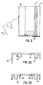
- FIG. 2A is a sectional view of the lid portion of the closure taken along line A-A in FIG. 1A;
- FIG. 2B is a sectional view of the lid portion of the closure taken along line B-B in FIG. 1A; and
- FIG. 3 is a side elevational view of the closure with the position of the hinged tongue in the open position shown in phantom.
- Referring now specifically to the drawings, wherein like numerals indicate like parts throughout, the tamper evident closure is generally designated 1 in FIG. 3, and comprises
abase cap 10 and alid 50, the latter being mounted onto the former by several equivalent friction fit locking elements. The structure of the base cap and lid shall now be discussed in turn. - The
base cap 10 has a generallyflat top 12 and a dependantannular skirt 14. In this embodiment, the dependantannular skirt 14 hasinternal threads 16 which mate with complementary external threads (not shown) on the neck of a corresponding bottle or other container. - The
base cap 10 has a dispensingorifice 18 formed onflat top 12 through which the contents of the container are normally dispensed. Although the dispensing orifice is shown to be circular in the figures, other shapes could be used as well. Thebase cap 10 has three generally cylindrical frictionfit locking cavities 20 formed projecting above theflat top 12. Thebase cap 10 has a tamper-evident band 22 extending from the bottom of the dependantannular skirt 14. The tamper-evident band comprises a plurality (e.g., 16 - depending on the size of the container neck) of equally spacedresilient tabs 24. These tabs are internally folded to slide over the container's external threads and annular shoulder as the cap is applied on the container. The tabs lock against the lower surface of the container's annular shoulder to retain the tamper-indicating band on the container as the base cap is removed. The separation of the tamper-indicating band and the base cap is the result of the forces generated through the breakable connectors. The breakable connectors are either formed in the molding process or are formed in a post molding cutting operation. (This tamper-evident band is further illustrated and discussed in applicant's U.S. Patent No. 4,506,795, the contents of which are herein incorporated by reference.) - The
lid 50 has a generally flat top 52 and a depending incompleteannular skirt 54. Thelid 50 has three friction fit locking plugs 56 depending from the flat top 52 (see FIG. 1B). Theplugs 56 engage the three friction fit lockingcavities 20 onflat top 12 of the base cap so as to lockingly attach thelid 50 onto thebase cap 10. - The
lid 50 has a hingedtongue portion 58, which is hinged tolid 50 by livinghinge 66.Tongue 58 is generally rectangular in shape except at thetongue skirt 62, where it forms the remainder of the annular skirt 54 (see FIGS. 1A and 2A). Depending from thetongue 58 is an annular orifice-sealingplug 60. Sealingplug 60 mates with dispensingorifice 18 so as to close theorifice 18, thus preventing further dispensing. This feature allows one to re-seal the container after the container has been accessed, but does not compromise the visual indication provided by the tamper evident tear lines that the container has been accessed (as is further discussed below). - Depending from
tongue skirt 62 ispull tab 64.Pull tab 64 is used for pulling thetongue 58 upward from a condition whereplug 60 is sealingly closingorifice 18, to a condition whereplug 60 is not sealingly closing orifice 18 (see FIG. 3), thus allowing the dispensing of the contents of the container. Tamper-evident tear lines 68 connect both sides oftongue 58 toflat top 52. - Tamper-
evident tear lines 68 also connect both sides oftongue skirt 62 to annular skirt 54 (see FIGS. 1B and 2B). These tear lines 68 are weakened portions oflid 50 that allow thetongue 58 to be separated from thelid 50 everywhere but at the livinghinge 66. The tear lines are sufficiently thin that they can be torn by those who need to access the container, while still being thick and strong enough so as not to be inadvertently torn.Tear lines 68, if torn, thus alert subsequent users that the tongue has been lifted from the lid at least once and the integrity of the container violated through the lid. - The closure is simple and inexpensive to manufacture, being mass-producible using simple conventional molds requiring no special tooling. The base cap will typically be manufactured of polypropylene (mainly to accommodate threads); the lid is preferably made of a high density polyethylene.
- The base cap and lid collectively provide a dual tamper evident device, in which the base portion provides a tamper evident closure between the bottle and the base cap, and the lid provides a tamper evident closure between the lid and the base cap. Although illustrated as separate components, the two may be provided as an integral assembly for even easier attachment to the bottle. Alternatively, the lid portion can be fitted to other forms of base cap, the only requirement being that the base cap have a means for securely locking the base cap to the lid to such an extent that the separation of the lid from the base cap results in the rupture of the tamper evident lines on the lid.
Claims (14)
- A tamper evident closure for sealing an open-topped container having a neck, the closure comprising a lid, said lid including:
an upper surface, said upper surface including a movable tongue portion that is attached to the lid by a living hinge and a plurality of regions that are fracturable, wherein the thickness of the fracturable regions is less than that of the adjacent portions of the lid;
an annular skirt depending from the top of the lid; and means for attaching the lid to a container. - The closure of claim 1, wherein the lid further comprises means for providing a secure connection between the lid and an underlying base cap or a container.
- The closure of claim 1, wherein the lid is made of a polymer.
- The closure of claim 1, wherein the tongue includes means for selectively sealing the tongue to an underlying base cap or container.
- The closure of claim 1, wherein the tongue includes a pull tab.
- The closure of claim 1, further comprising a base cap for attachment to a container and means for providing a secure connection between the lid and the base cap.
- The closure of claim 6, wherein the hinged tongue includes a sealing plug, and the base cap includes:
a top surface that defines an orifice, said orifice being configured to mate with the sealing plug on the hinged tongue; and
an annular skirt that is dependant from the top surface of the base cap. - The closure of claim 6, wherein the base cap is equipped with a tamper evident feature that comprises a series of tabs equally space about the periphery of the annular skirt and a series of breakable connectors.
- The closure of claim 6, wherein the base cap is made of a polymer.
- The closure of claim 6, wherein the base cap includes an internal thread.
- The closure of claim 6, wherein the base cap and lid are formed via injection molding.
- A method for providing a tamper evident closure, the method comprising the steps of:
attaching a base cap to a container, said base cap being equipped with a tamper evident feature; and
securely affixing a lid to the base cap, said lid having an upper surface that includes a movable tongue portion that is attached to the lid by a living hinge and a plurality of regions that are fracturable, wherein the thickness of the fracturable regions is less than that of the adjacent portions of the lid so that the interior of the container cannot be accessed through the lid without rupturing the fracturable regions. - The method of claim 12, wherein the tamper evident feature about the base cap comprises a series of tabs equally space about the periphery of the annular skirt and a series of breakable connectors.
- The method of claim 12, wherein the base cap is integral with the lid.
Applications Claiming Priority (2)
| Application Number | Priority Date | Filing Date | Title |
|---|---|---|---|
| US4307093A | 1993-04-02 | 1993-04-02 | |
| US43070 | 1993-04-02 |
Publications (2)
| Publication Number | Publication Date |
|---|---|
| EP0618146A2 true EP0618146A2 (en) | 1994-10-05 |
| EP0618146A3 EP0618146A3 (en) | 1995-04-05 |
Family
ID=21925328
Family Applications (1)
| Application Number | Title | Priority Date | Filing Date |
|---|---|---|---|
| EP94101628A Withdrawn EP0618146A3 (en) | 1993-04-02 | 1994-02-03 | Tamper-evident closure. |
Country Status (3)
| Country | Link |
|---|---|
| EP (1) | EP0618146A3 (en) |
| AU (1) | AU5479994A (en) |
| CA (1) | CA2114972A1 (en) |
Cited By (2)
| Publication number | Priority date | Publication date | Assignee | Title |
|---|---|---|---|---|
| FR2791642A1 (en) * | 1999-04-02 | 2000-10-06 | Crown Cork & Seal Tech Corp | Plastics stopper for drinks bottle has cap with skirt and hinged cover to selectively close outlet opening |
| DE102007015100A1 (en) | 2007-03-29 | 2008-10-02 | Merck Patent Gmbh | Container for several test strips |
Citations (4)
| Publication number | Priority date | Publication date | Assignee | Title |
|---|---|---|---|---|
| FR2309425A1 (en) * | 1975-04-29 | 1976-11-26 | Angelino Roger | Two-part plastics pouring stopper - has inner part inserted into bottle neck and covering cap clipped into place |
| US4506795A (en) * | 1983-02-18 | 1985-03-26 | Kerr Glass Manufacturing Corporation | Tamper-evident closure |
| EP0167783A1 (en) * | 1984-06-28 | 1986-01-15 | ZELLER PLASTIK Koehn, Gräbner & Co. | Closure device for a container and such a container |
| US5201440A (en) * | 1991-10-11 | 1993-04-13 | Seaquist Closures, A Division Of Pittway Corporation | Closure with tamper-evident tear-off panel unitary with a flow control element |
-
1994
- 1994-01-31 AU AU54799/94A patent/AU5479994A/en not_active Abandoned
- 1994-02-03 EP EP94101628A patent/EP0618146A3/en not_active Withdrawn
- 1994-02-04 CA CA002114972A patent/CA2114972A1/en not_active Abandoned
Patent Citations (4)
| Publication number | Priority date | Publication date | Assignee | Title |
|---|---|---|---|---|
| FR2309425A1 (en) * | 1975-04-29 | 1976-11-26 | Angelino Roger | Two-part plastics pouring stopper - has inner part inserted into bottle neck and covering cap clipped into place |
| US4506795A (en) * | 1983-02-18 | 1985-03-26 | Kerr Glass Manufacturing Corporation | Tamper-evident closure |
| EP0167783A1 (en) * | 1984-06-28 | 1986-01-15 | ZELLER PLASTIK Koehn, Gräbner & Co. | Closure device for a container and such a container |
| US5201440A (en) * | 1991-10-11 | 1993-04-13 | Seaquist Closures, A Division Of Pittway Corporation | Closure with tamper-evident tear-off panel unitary with a flow control element |
Cited By (4)
| Publication number | Priority date | Publication date | Assignee | Title |
|---|---|---|---|---|
| FR2791642A1 (en) * | 1999-04-02 | 2000-10-06 | Crown Cork & Seal Tech Corp | Plastics stopper for drinks bottle has cap with skirt and hinged cover to selectively close outlet opening |
| DE102007015100A1 (en) | 2007-03-29 | 2008-10-02 | Merck Patent Gmbh | Container for several test strips |
| WO2008119421A1 (en) | 2007-03-29 | 2008-10-09 | Merck Patent Gmbh | Container for a plurality of test strips |
| US7997435B2 (en) | 2007-03-29 | 2011-08-16 | Merck Patent Gmbh | Container for a plurality of test strips |
Also Published As
| Publication number | Publication date |
|---|---|
| EP0618146A3 (en) | 1995-04-05 |
| CA2114972A1 (en) | 1994-10-03 |
| AU5479994A (en) | 1994-10-06 |
Similar Documents
| Publication | Publication Date | Title |
|---|---|---|
| US4709823A (en) | Tamper evident bottle or package closure | |
| US5685444A (en) | Tamper-evident hinged closure cap construction | |
| US4747500A (en) | Tamper indicating transparent closure | |
| USRE39867E1 (en) | Tamper-evident container closure | |
| US5097974A (en) | Tamper-evident closures | |
| US4948003A (en) | Container and closure with internal tamper indication | |
| US4795044A (en) | Tamper evident closure with snap-type hinge cap | |
| US4747498A (en) | Safety dispensing closure-container package | |
| US5738231A (en) | Tamper indicating threaded closure-container package | |
| US5129531A (en) | Closure assembly with breakaway tamper evident membrane | |
| US4852751A (en) | Tamper indicating container-closure package | |
| US5085333A (en) | Tamper evident container overcap molded in straight draw mold | |
| US4570810A (en) | Cap with tamper indicating band | |
| USRE40003E1 (en) | Tamper-evident container closure | |
| US5088613A (en) | Tamper evident closure | |
| EP0390412A1 (en) | Tamper resistant closure cap for containers | |
| US5855288A (en) | Resealable closure | |
| US4784281A (en) | Tamper-evident closures | |
| US4817807A (en) | Tamper-evident container | |
| JP2660552B2 (en) | Hinged cap | |
| EP0618146A2 (en) | Tamper-evident closure | |
| CA1302950C (en) | Tamper indicator lid | |
| JP4342839B2 (en) | Easy-open container lid | |
| US4572389A (en) | Tamper indicating screw cap with satellite ring | |
| JP3665973B2 (en) | Hinge cap to prevent tampering |
Legal Events
| Date | Code | Title | Description |
|---|---|---|---|
| PUAI | Public reference made under article 153(3) epc to a published international application that has entered the european phase |
Free format text: ORIGINAL CODE: 0009012 |
|
| AK | Designated contracting states |
Kind code of ref document: A2 Designated state(s): AT BE CH DE DK ES FR GB GR IE IT LI LU MC NL PT SE |
|
| PUAL | Search report despatched |
Free format text: ORIGINAL CODE: 0009013 |
|
| AK | Designated contracting states |
Kind code of ref document: A3 Designated state(s): AT BE CH DE DK ES FR GB GR IE IT LI LU MC NL PT SE |
|
| 17P | Request for examination filed |
Effective date: 19951004 |
|
| STAA | Information on the status of an ep patent application or granted ep patent |
Free format text: STATUS: THE APPLICATION HAS BEEN WITHDRAWN |
|
| 18W | Application withdrawn |
Withdrawal date: 19951211 |