EP4195486A1 - Procédé de commande d'un redresseur actif d'une éolienne - Google Patents
Procédé de commande d'un redresseur actif d'une éolienne Download PDFInfo
- Publication number
- EP4195486A1 EP4195486A1 EP21213468.8A EP21213468A EP4195486A1 EP 4195486 A1 EP4195486 A1 EP 4195486A1 EP 21213468 A EP21213468 A EP 21213468A EP 4195486 A1 EP4195486 A1 EP 4195486A1
- Authority
- EP
- European Patent Office
- Prior art keywords
- converter
- carrier signal
- generator
- distortion
- controlling
- Prior art date
- Legal status (The legal status is an assumption and is not a legal conclusion. Google has not performed a legal analysis and makes no representation as to the accuracy of the status listed.)
- Pending
Links
- 238000000034 method Methods 0.000 title claims abstract description 68
- 230000008878 coupling Effects 0.000 claims description 3
- 238000010168 coupling process Methods 0.000 claims description 3
- 238000005859 coupling reaction Methods 0.000 claims description 3
- 238000009434 installation Methods 0.000 description 13
- 238000001514 detection method Methods 0.000 description 4
- 238000005259 measurement Methods 0.000 description 4
- 230000001360 synchronised effect Effects 0.000 description 4
- 230000000630 rising effect Effects 0.000 description 2
- 230000004913 activation Effects 0.000 description 1
- 230000000712 assembly Effects 0.000 description 1
- 238000000429 assembly Methods 0.000 description 1
- 238000004364 calculation method Methods 0.000 description 1
- 238000010276 construction Methods 0.000 description 1
- 230000001419 dependent effect Effects 0.000 description 1
- 230000000694 effects Effects 0.000 description 1
- 230000005611 electricity Effects 0.000 description 1
- 238000004088 simulation Methods 0.000 description 1
- 230000001131 transforming effect Effects 0.000 description 1
Images


Classifications
-
- H—ELECTRICITY
- H02—GENERATION; CONVERSION OR DISTRIBUTION OF ELECTRIC POWER
- H02M—APPARATUS FOR CONVERSION BETWEEN AC AND AC, BETWEEN AC AND DC, OR BETWEEN DC AND DC, AND FOR USE WITH MAINS OR SIMILAR POWER SUPPLY SYSTEMS; CONVERSION OF DC OR AC INPUT POWER INTO SURGE OUTPUT POWER; CONTROL OR REGULATION THEREOF
- H02M7/00—Conversion of ac power input into dc power output; Conversion of dc power input into ac power output
- H02M7/02—Conversion of ac power input into dc power output without possibility of reversal
- H02M7/04—Conversion of ac power input into dc power output without possibility of reversal by static converters
- H02M7/12—Conversion of ac power input into dc power output without possibility of reversal by static converters using discharge tubes with control electrode or semiconductor devices with control electrode
- H02M7/21—Conversion of ac power input into dc power output without possibility of reversal by static converters using discharge tubes with control electrode or semiconductor devices with control electrode using devices of a triode or transistor type requiring continuous application of a control signal
- H02M7/217—Conversion of ac power input into dc power output without possibility of reversal by static converters using discharge tubes with control electrode or semiconductor devices with control electrode using devices of a triode or transistor type requiring continuous application of a control signal using semiconductor devices only
- H02M7/219—Conversion of ac power input into dc power output without possibility of reversal by static converters using discharge tubes with control electrode or semiconductor devices with control electrode using devices of a triode or transistor type requiring continuous application of a control signal using semiconductor devices only in a bridge configuration
-
- H—ELECTRICITY
- H02—GENERATION; CONVERSION OR DISTRIBUTION OF ELECTRIC POWER
- H02J—CIRCUIT ARRANGEMENTS OR SYSTEMS FOR SUPPLYING OR DISTRIBUTING ELECTRIC POWER; SYSTEMS FOR STORING ELECTRIC ENERGY
- H02J3/00—Circuit arrangements for ac mains or ac distribution networks
- H02J3/38—Arrangements for parallely feeding a single network by two or more generators, converters or transformers
- H02J3/46—Controlling of the sharing of output between the generators, converters, or transformers
-
- F—MECHANICAL ENGINEERING; LIGHTING; HEATING; WEAPONS; BLASTING
- F03—MACHINES OR ENGINES FOR LIQUIDS; WIND, SPRING, OR WEIGHT MOTORS; PRODUCING MECHANICAL POWER OR A REACTIVE PROPULSIVE THRUST, NOT OTHERWISE PROVIDED FOR
- F03D—WIND MOTORS
- F03D7/00—Controlling wind motors
- F03D7/02—Controlling wind motors the wind motors having rotation axis substantially parallel to the air flow entering the rotor
- F03D7/028—Controlling wind motors the wind motors having rotation axis substantially parallel to the air flow entering the rotor controlling wind motor output power
-
- H—ELECTRICITY
- H02—GENERATION; CONVERSION OR DISTRIBUTION OF ELECTRIC POWER
- H02J—CIRCUIT ARRANGEMENTS OR SYSTEMS FOR SUPPLYING OR DISTRIBUTING ELECTRIC POWER; SYSTEMS FOR STORING ELECTRIC ENERGY
- H02J3/00—Circuit arrangements for ac mains or ac distribution networks
- H02J3/38—Arrangements for parallely feeding a single network by two or more generators, converters or transformers
- H02J3/381—Dispersed generators
-
- H—ELECTRICITY
- H02—GENERATION; CONVERSION OR DISTRIBUTION OF ELECTRIC POWER
- H02K—DYNAMO-ELECTRIC MACHINES
- H02K7/00—Arrangements for handling mechanical energy structurally associated with dynamo-electric machines, e.g. structural association with mechanical driving motors or auxiliary dynamo-electric machines
- H02K7/18—Structural association of electric generators with mechanical driving motors, e.g. with turbines
- H02K7/1807—Rotary generators
- H02K7/1823—Rotary generators structurally associated with turbines or similar engines
- H02K7/183—Rotary generators structurally associated with turbines or similar engines wherein the turbine is a wind turbine
-
- H—ELECTRICITY
- H02—GENERATION; CONVERSION OR DISTRIBUTION OF ELECTRIC POWER
- H02M—APPARATUS FOR CONVERSION BETWEEN AC AND AC, BETWEEN AC AND DC, OR BETWEEN DC AND DC, AND FOR USE WITH MAINS OR SIMILAR POWER SUPPLY SYSTEMS; CONVERSION OF DC OR AC INPUT POWER INTO SURGE OUTPUT POWER; CONTROL OR REGULATION THEREOF
- H02M1/00—Details of apparatus for conversion
- H02M1/0043—Converters switched with a phase shift, i.e. interleaved
-
- H—ELECTRICITY
- H02—GENERATION; CONVERSION OR DISTRIBUTION OF ELECTRIC POWER
- H02M—APPARATUS FOR CONVERSION BETWEEN AC AND AC, BETWEEN AC AND DC, OR BETWEEN DC AND DC, AND FOR USE WITH MAINS OR SIMILAR POWER SUPPLY SYSTEMS; CONVERSION OF DC OR AC INPUT POWER INTO SURGE OUTPUT POWER; CONTROL OR REGULATION THEREOF
- H02M7/00—Conversion of ac power input into dc power output; Conversion of dc power input into ac power output
- H02M7/02—Conversion of ac power input into dc power output without possibility of reversal
- H02M7/04—Conversion of ac power input into dc power output without possibility of reversal by static converters
- H02M7/12—Conversion of ac power input into dc power output without possibility of reversal by static converters using discharge tubes with control electrode or semiconductor devices with control electrode
- H02M7/21—Conversion of ac power input into dc power output without possibility of reversal by static converters using discharge tubes with control electrode or semiconductor devices with control electrode using devices of a triode or transistor type requiring continuous application of a control signal
- H02M7/217—Conversion of ac power input into dc power output without possibility of reversal by static converters using discharge tubes with control electrode or semiconductor devices with control electrode using devices of a triode or transistor type requiring continuous application of a control signal using semiconductor devices only
-
- H—ELECTRICITY
- H02—GENERATION; CONVERSION OR DISTRIBUTION OF ELECTRIC POWER
- H02P—CONTROL OR REGULATION OF ELECTRIC MOTORS, ELECTRIC GENERATORS OR DYNAMO-ELECTRIC CONVERTERS; CONTROLLING TRANSFORMERS, REACTORS OR CHOKE COILS
- H02P9/00—Arrangements for controlling electric generators for the purpose of obtaining a desired output
- H02P9/10—Control effected upon generator excitation circuit to reduce harmful effects of overloads or transients, e.g. sudden application of load, sudden removal of load, sudden change of load
- H02P9/102—Control effected upon generator excitation circuit to reduce harmful effects of overloads or transients, e.g. sudden application of load, sudden removal of load, sudden change of load for limiting effects of transients
-
- F—MECHANICAL ENGINEERING; LIGHTING; HEATING; WEAPONS; BLASTING
- F05—INDEXING SCHEMES RELATING TO ENGINES OR PUMPS IN VARIOUS SUBCLASSES OF CLASSES F01-F04
- F05B—INDEXING SCHEME RELATING TO WIND, SPRING, WEIGHT, INERTIA OR LIKE MOTORS, TO MACHINES OR ENGINES FOR LIQUIDS COVERED BY SUBCLASSES F03B, F03D AND F03G
- F05B2270/00—Control
- F05B2270/10—Purpose of the control system
- F05B2270/103—Purpose of the control system to affect the output of the engine
- F05B2270/1033—Power (if explicitly mentioned)
-
- H—ELECTRICITY
- H02—GENERATION; CONVERSION OR DISTRIBUTION OF ELECTRIC POWER
- H02J—CIRCUIT ARRANGEMENTS OR SYSTEMS FOR SUPPLYING OR DISTRIBUTING ELECTRIC POWER; SYSTEMS FOR STORING ELECTRIC ENERGY
- H02J2300/00—Systems for supplying or distributing electric power characterised by decentralized, dispersed, or local generation
- H02J2300/20—The dispersed energy generation being of renewable origin
- H02J2300/28—The renewable source being wind energy
-
- H—ELECTRICITY
- H02—GENERATION; CONVERSION OR DISTRIBUTION OF ELECTRIC POWER
- H02M—APPARATUS FOR CONVERSION BETWEEN AC AND AC, BETWEEN AC AND DC, OR BETWEEN DC AND DC, AND FOR USE WITH MAINS OR SIMILAR POWER SUPPLY SYSTEMS; CONVERSION OF DC OR AC INPUT POWER INTO SURGE OUTPUT POWER; CONTROL OR REGULATION THEREOF
- H02M5/00—Conversion of ac power input into ac power output, e.g. for change of voltage, for change of frequency, for change of number of phases
- H02M5/40—Conversion of ac power input into ac power output, e.g. for change of voltage, for change of frequency, for change of number of phases with intermediate conversion into dc
- H02M5/42—Conversion of ac power input into ac power output, e.g. for change of voltage, for change of frequency, for change of number of phases with intermediate conversion into dc by static converters
- H02M5/44—Conversion of ac power input into ac power output, e.g. for change of voltage, for change of frequency, for change of number of phases with intermediate conversion into dc by static converters using discharge tubes or semiconductor devices to convert the intermediate dc into ac
- H02M5/453—Conversion of ac power input into ac power output, e.g. for change of voltage, for change of frequency, for change of number of phases with intermediate conversion into dc by static converters using discharge tubes or semiconductor devices to convert the intermediate dc into ac using devices of a triode or transistor type requiring continuous application of a control signal
- H02M5/458—Conversion of ac power input into ac power output, e.g. for change of voltage, for change of frequency, for change of number of phases with intermediate conversion into dc by static converters using discharge tubes or semiconductor devices to convert the intermediate dc into ac using devices of a triode or transistor type requiring continuous application of a control signal using semiconductor devices only
- H02M5/4585—Conversion of ac power input into ac power output, e.g. for change of voltage, for change of frequency, for change of number of phases with intermediate conversion into dc by static converters using discharge tubes or semiconductor devices to convert the intermediate dc into ac using devices of a triode or transistor type requiring continuous application of a control signal using semiconductor devices only having a rectifier with controlled elements
-
- H—ELECTRICITY
- H02—GENERATION; CONVERSION OR DISTRIBUTION OF ELECTRIC POWER
- H02P—CONTROL OR REGULATION OF ELECTRIC MOTORS, ELECTRIC GENERATORS OR DYNAMO-ELECTRIC CONVERTERS; CONTROLLING TRANSFORMERS, REACTORS OR CHOKE COILS
- H02P2101/00—Special adaptation of control arrangements for generators
- H02P2101/15—Special adaptation of control arrangements for generators for wind-driven turbines
-
- H—ELECTRICITY
- H02—GENERATION; CONVERSION OR DISTRIBUTION OF ELECTRIC POWER
- H02P—CONTROL OR REGULATION OF ELECTRIC MOTORS, ELECTRIC GENERATORS OR DYNAMO-ELECTRIC CONVERTERS; CONTROLLING TRANSFORMERS, REACTORS OR CHOKE COILS
- H02P2205/00—Indexing scheme relating to controlling arrangements characterised by the control loops
- H02P2205/01—Current loop, i.e. comparison of the motor current with a current reference
Definitions
- the present invention relates to a method for controlling a converter, preferably an active rectifier on the generator side of a power converter of a wind energy plant.
- converters are usually used to generate electricity.
- the converters are often designed as so-called converter systems, i.e. several converters or converter modules or converter submodules are connected together, preferably in parallel, in particular to form a converter system with higher power.
- the converters or the converter systems can be controlled using a wide variety of methods, for example using a hysteresis method, such as the tolerance band method, or using a modulation method, such as pulse duration modulation.
- a hysteresis method such as the tolerance band method
- a modulation method such as pulse duration modulation.
- the hysteresis methods are usually designed as direct current control methods with a closed control loop and have fast dynamics and high robustness, in particular with non-linear control behavior and broadband noise.
- the modulation methods usually have a fixed clock frequency, which leads to harmonics with a multiple of the modulation frequency, which are often in the audible range.
- EMC electromagnetic compatibility
- the object of the present invention is therefore to address at least one of the problems mentioned above.
- a method for controlling converters, in particular active rectifiers of a wind turbine is to be provided which has only a small current ripple in the generator and thus leads to small force fluctuations in the air gap of the generator and less noise.
- a method for controlling a converter preferably an active rectifier on the generator side of a power converter of a wind energy installation, comprising the steps of: specifying a setpoint for the converter; specifying a carrier signal for the converter; detecting an actual value; determining a distortion variable from the target value and the actual value; and determining drive signals for the converter depending on the distortion magnitude and the carrier signal.
- a method for controlling an active rectifier of a wind turbine which determines the driver signals for the active rectifier, in particular directly, from a measurement deviation, preferably without calculating additional voltage setpoints, such as with conventional pulse duration modulation (PWM). .
- PWM pulse duration modulation
- the particular advantage of the proposed method is that general system parameters are not absolutely necessary, since the driver signals are preferably determined from a measurement deviation. As a result, the proposed method can be parameterized and implemented more easily than, for example, previously known PWM methods.
- a desired value and a signal, in particular an additional signal, are initially specified for the converter.
- the setpoint is preferably a setpoint specification for a physical variable, such as a current to be generated by the converter.
- the desired value is preferably a current desired value for an alternating current to be generated by an active rectifier, for example in the form of a value or a function.
- The, in particular additional, carrier signal is, for example, a comparison or adjustment signal or a ramp signal.
- the carrier signal is preferably a triangular signal.
- the amplitude and/or the frequency and/or the period and/or the width of the carrier signal can be adjusted.
- the amplitude and/or the frequency and/or the period and/or the width of the carrier signal is/are particularly preferably varied during operation, in particular in order to produce what is known as a smearing of the frequency band.
- the frequency of the carrier signal is preferably chosen as a function of structural dynamics, for example in order to minimize the effects on the noise emissions of a corresponding generator. If the method described here is used, for example, to control an active rectifier connected to a generator, the carrier signal preferably has a frequency between 200. In a further step, an actual value is then recorded and compared with the setpoint value, in particular to determine a distortion variable .
- the actual value is preferably a physical variable that corresponds in particular to the desired value, such as the current generated by the converter.
- the actual value is preferably an actual current value, in particular an alternating current generated by an active rectifier.
- the distortion variable determined from the target value and the actual value, for example by difference, can also be referred to as a measurement or control deviation.
- the method thus has at least one control loop and is preferably embodied as a direct current control method, in particular in order to generate a three-phase alternating current for a stator of a generator of a wind turbine.
- the distortion variable is preferably formed from a difference between the desired value and the actual value and, if the desired value and the actual value represent a current, can also be referred to as the distortion current.
- the distortion quantity can also be a value or a function, in particular the distortion quantity is a differential current that changes over time and that represents a difference between the setpoint current and the actual current of a converter, in particular an active rectifier.
- the driver signals for the converter are then determined from the distortion magnitude and the carrier signal.
- the active rectifier is designed as a B6C rectifier with six switches, in particular power switches, then six driver signals are determined accordingly, one driver signal for each switch.
- the driver signals can be determined, for example, by comparing the distortion magnitude with the carrier signal.
- the distortion quantity is integrated into a modulation signal and compared with the carrier signal, with the points of intersection between the modulation signal and the carrier signal forming a trigger for generating a corresponding driver signal.
- driver signals are generated by adjusting the distortion variable and/or an extended distortion variable and/or a modulation signal with the carrier signal.
- the carrier signal is a ramp signal
- the method is implemented as a so-called ramp comparison method.
- the driver signals are therefore used in particular to switch the switches of the converter, in particular the switches of the active rectifier, preferably in order to generate an electrical alternating current in the stator of the generator of the wind turbine, which essentially corresponds to the setpoint value, i.e. a setpoint current.
- the method described herein preferably also includes the step of switching at least one switch of the converter, in particular the active rectifier, as a function of the driver signals, in particular in such a way that the converter, in particular the active rectifier, generates an electrical alternating current in the stator of the generator of the wind turbine , which essentially corresponds to the target value.
- the method described here can be implemented with or without hysteresis.
- the method described herein is preferably carried out without hysteresis.
- the current quality of a converter in particular an active rectifier, can be improved by the method described here.
- the quality of the generator's stator current can be significantly improved, thereby reducing the generator's noise emissions.
- the distortion variable is preferably converted, in particular amplified and/or integrated, into an expanded distortion variable and/or a modulation signal, which preferably takes at least one system state of the converter into account.
- the distortion variable that is to say in particular the difference between the desired value and the actual value, is therefore, for example, amplified and/or integrated, in particular in order to reduce a permanent control deviation.
- an I element or PI element can be implemented in the control unit, for example, with its parameters preferably being set as a function of the electrical string of the wind turbine, for example the stator inductance or the stator resistance.
- the amount of distortion can also be increased, for example by a factor of between 2 and 10, in particular in order to improve the signal quality.
- the gain is preferably set as a function of the electrical strand of the wind energy installation, for example as a function of a stator inductance or a stator resistance.
- a corresponding system state can also be taken into account.
- the driver signals are then preferably determined accordingly depending on the expanded distortion quantity or the modulation signal and the carrier signal.
- driver signals are generated by adjusting the expanded distortion variable or the modulation signal with the carrier signal, e.g. as in 6 shown.
- the driver signals are determined as a function of an offset which, in particular, takes into account an operating point of the converter.
- the offset can, for example, be in the form of a compensation value, such as a compensation current, which takes into account an operating point of the active rectifier and/or the wind energy installation.
- a compensation value such as a compensation current
- the offset is preferably determined offline, for example by simulation or calculation, and set accordingly in a control unit.
- the offset is therefore preferably a calculated variable that takes into account an operating point, for example of the converter or of a generator or system connected to the converter.
- the steady state error can be minimized or eliminated by appropriately precise selection of the offset.
- At least one I or PI controller is preferably used in order to further minimize or eliminate precisely that remaining control deviation
- the driver signals are determined by means of a pre-coupling of the desired value.
- the feed-forward thus minimizes the complexity of the controller, in particular if a variable that is dependent on the operating point also flows into the controller, for example, such as the offset described above or below.
- any I or PI controllers for example, only intervene if the distortion variable, i.e. the remaining control deviation, is too large.
- the pre-coupling relieves the converter control.
- the target value is preferably a current target value, in particular for a current of an electrical (stator) system of a generator of a wind energy installation.
- the method is therefore implemented in particular as current regulation, preferably for an active rectifier on the generator side of a wind turbine.
- driver signals are preferably determined as a function of a desired current value, in particular for an active rectifier.
- the carrier signal for the converter is preferably for setting a single-phase current, preferably an electrical (stator) system of a generator of a wind energy plant.
- stator currents of a generator are set, preferably individually, using the method described herein.
- the distortion current is determined individually for each phase and compared with the signal in order to determine the driver signals accordingly for each phase individually.
- the distortion current is preferably present in abc coordinates.
- the carrier signal is preferably generated by a signal generator and has at least one of the following forms: triangle, sine, square.
- the signal for determining the driver signals is thus preferably generated by a signal generator, for example as a triangular or sawtooth function.
- the triangular function has two symmetrical flanks.
- the flanks rise, for example, at an angle of between 30° and 60°, preferably between 40° and 50°, more preferably approx. 45°.
- the triangular function can also be asymmetrical, for example the rising flank has an angle of approximately 45° and the falling flank has an angle of approximately 60°.
- the sawtooth function has at least one edge of 90°, for example the rising edge or the falling edge.
- the other edge then has, for example, an angle between 30° and 60°, preferably between 40° and 50°, more preferably approximately 45°.
- the control variable is then compared with this carrier signal in order to generate the driver signals.
- the method described above or below is therefore preferably designed like or as a ramp comparison method, preferably with a triangle.
- the carrier signal preferably has an amplitude and a frequency.
- the distortion quantity and/or the extended distortion quantity and/or the modulation signal preferably has an amplitude and a frequency which is in particular smaller than the amplitude and/or the frequency of the carrier signal.
- the amplitude of the carrier signal is twice the amplitude of the distortion quantity.
- the carrier signal has a greater amplitude than the amplitude of the signal with which it is compared, ie for example the distortion variable or the expanded distortion variable or the modulation signal.
- the amplitude of the carrier signal is normalized to 1 and the amplitudes of the signal with which it is matched are smaller.
- the amplitude of the carrier signal is constant or is varied.
- the carrier signal has a frequency, for example between 200 Hz and 2500 Hz, which is greater than the frequency of the signal with which it is matched, ie for example the distortion variable or the extended distortion variable or the modulation signal.
- the distortion magnitude has, for example, a frequency between 10Hz and 200Hz, for example around 50Hz or 60Hz.
- the actual value is preferably an actual current value, in particular for a current of an electrical (stator) system of a generator of a wind energy installation.
- the actual current value is preferably detected at the input of the converter, in particular at the input of the active rectifier, in particular as a three-phase alternating current.
- the actual current value can, for example, be recorded as the total current for an entire system, for example a three-phase stator system, and/or recorded individually for each phase of the system.
- the actual current value is preferably transformed or converted into d/q and/or abc coordinates, in particular in order to compare them with the d/q and/or abc coordinates of the desired current value.
- the actual value preferably includes both a three-phase overall system and each phase of the overall system.
- the method takes into account both the entire three-phase (stator) system and each phase of this system individually.
- the actual value can be compared with a target value in d/q coordinates and additionally or subsequently again in abc coordinates.
- the entire system is preferably recorded as a total current in d/q coordinates.
- the target value and/or the actual value and/or the distortion quantity and/or an offset is or is present in d/q coordinates.
- the method described above or below be carried out at least partially in d/q coordinates, in particular in order to take the entire (stator) system into account.
- at least the entire system is taken into account as a total current in d/q coordinates.
- the method can be significantly simplified and a PI controller can be used to control the converter, in particular the active rectifier, which in particular has no permanent control deviation having.
- the method described above or below is preferably carried out for a first electrical (stator) system of a generator of a wind turbine with a first carrier signal, and in parallel, in particular at the same time, also for a second electrical (stator) system of the same generator with a second carrier signal , wherein the first carrier signal and the second carrier signal are essentially the same, but are offset by a phase angle to one another, the phase angle being in particular between 30° and 120°, preferably between 80° and 100°, in particular by approximately 90° .
- the method is therefore carried out in particular with a phase offset in the carrier signal.
- phase offset of approximately 90° leads to low-noise operation with two parallel (stator) systems.
- the carrier signal is preferably varied during operation, in particular by means of a ramp function depending on the rotor speed of the generator of the wind turbine, for example by a value in a range between 0 and 10 percent, preferably around 5 percent.
- the amplitude and/or the frequency and/or the period and/or the width is/are particularly preferably varied during operation, in particular in order to produce what is known as a smearing of the frequency band.
- the carrier signal has a variable frequency that varies with a ramp function, e.g. around a specific frequency, in particular with a period that is proportional, in particular indirectly proportional, to the number of pole pairs and/or the rotor speed of the generator.
- any harmonics in the alternating current can be reduced, in particular in such a way that smaller filters or no filters at all are necessary in order to ensure low-noise generator operation.
- the frequency of the carrier signal is between 500 Hz and 2500 Hz, for example 700 Hz, and is varied by approximately 5 percent, ie 35 Hz.
- a wind energy plant comprising a converter and a control unit, the converter being designed as a power converter and being operated by means of the control unit using a method described above or below.
- the wind energy installation is designed, for example, as a lift rotor with a horizontal axis of rotation and preferably has three rotor blades on an aerodynamic rotor on the windward side.
- the electrical strand of the wind turbine connected to the aerodynamic rotor essentially comprises a generator, a converter connected to the generator and a (mains) connection connected to the converter, in order to connect the wind turbine to an electrical wind farm network or an electrical supply network, for example.
- the generator is preferably designed as a synchronous generator, for example as an externally excited synchronous generator or as a permanently excited synchronous generator.
- the converter is preferably designed as a power converter. This means in particular that the converter is used to convert electrical power generated by the generator.
- the converter is also preferably integrated as a full converter in the wind energy plant. This means in particular that the entire electrical power generated by the generator is routed via the converter and is thus converted by it.
- the generator preferably has two stator systems, in particular offset by 30°, which are each connected to an active rectifier, which are each controlled separately from one another via a control unit.
- control units work in particular with a method described above or below, the methods in particular having a phase offset in the carrier signal of, for example, approximately 90°.
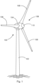
- FIG. 1 shows a schematic and exemplary perspective view of a wind turbine 100.
- the wind energy installation 100 is designed as a lift rotor with a horizontal axis and three rotor blades 200 on the windward side, in particular as a horizontal rotor.
- An aerodynamic rotor 106 with a hub 110 is arranged on the nacelle 104 .
- Three rotor blades 108 are arranged on the hub 110, in particular symmetrically to the hub 110, preferably offset by 120°.
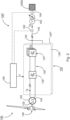
- FIG figure 2 shows, schematically and by way of example, an electrical string 100' of a wind turbine 100, as preferably shown in FIG figure 1 shown.
- the wind power plant 100 has an aerodynamic rotor 106 which is mechanically connected to a generator 120 of the wind power plant 100 .
- the generator 120 is preferably designed as a 6-phase synchronous generator, in particular with two three-phase systems 122, 124, which are phase-shifted by 30 degrees and are decoupled from one another.
- the generator 120 is connected to an electrical supply network 2000 or connected to the electrical supply network 2000 via a converter 130 and by means of a transformer 150 .
- the converter 130 In order to convert the electrical power generated by the generator 120 into a current iG to be fed in, the converter 130 has at least one converter module 130', 130" for each of the electrical systems 122, 124, with the converter modules 130', 130" being essentially identical in construction are.
- the converter modules 130', 130'' have an active rectifier 132' at a converter module input.
- the active rectifier 132' is electrically connected to an inverter 137', for example via a DC voltage line 135' or a DC voltage intermediate circuit.
- the converter 130 or the converter modules 130′, 130′′ is preferably designed as a direct converter (back-to-back converter).
- the two electrically three-phase systems 122, 124, which are decoupled from one another on the stator side, are combined, for example, on the grid side at a node 140 to form a three-phase overall system 142, which carries the total current iG to be fed in.
- a wind energy plant transformer 150 is also provided at the output of the wind energy plant, which is preferably connected in star-delta and connects the wind energy plant 100 to the electrical supply network 2000.
- the electrical supply network 2000 to which the wind energy installation 100, 100' is connected by means of the transformer 150 can be, for example, a wind farm network or an electrical supply or distribution network.
- a wind power plant control unit 160 is also provided for controlling the wind power plant 100 or the electrical string 100′.
- the wind energy installation control unit 160 is set up in particular to set a total current iG to be fed in, in particular by controlling the active rectifiers 132', 132'' or inverters 137', 137''.
- the active rectifiers 132', 132" are activated in particular as described above or below, preferably by means of or as a function of the driver signals T.
- control unit also has voltage detection means 164 which are set up to detect a mains voltage, in particular of the electrical supply network 2000 .
- the wind turbine control unit 160 is also set up to also detect the phase angle and the amplitude of the current iG to be fed.
- Wind turbine control unit 160 also includes a control unit 1000, described above or below, for converter 130.
- the control unit 1000 is therefore set up in particular to control the entire converter 130 with its two converter modules 130', 130", in particular as in 4 shown to be controlled with driver signals T.
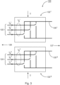
- FIG. 3 shows schematically and by way of example the structure of a converter 130, in particular an active rectifier 132', 132", as in 2 shown.
- the converter 130 includes, in particular, two active rectifiers 132', 132''.
- the active rectifiers 132', 132" are each connected on the generator side to a system 122, 124 of a generator 120 and, for example, via a DC voltage 135', 135" to an inverter 137', 137", as in particular in 2 shown.
- the active rectifiers 132′, 132′′ are each controlled by means of drive signals T by the control unit 1000 described above or below and/or by a method described above or below, in particular by a three-phase alternating current i a ′, ib ′, ic ′ , i a ", i b ", i c "in the stator of the generator 120.
- Figure 4A shows a schematic and exemplary structure of a control unit 1000 of a converter 130, in particular for an active rectifier 132', 132".
- the control unit 1000 determines a distortion variable E from a target value S* and an actual value S.
- the desired value S* and the actual value S are preferably physical variables of the converter, such as an alternating current I_soll to be generated by the active rectifier 132', 132" or an alternating current I_actual generated by the active rectifier 132', 132".
- the distortion variable E is preferably determined from a difference between the desired value S* and the actual value S, and can therefore also be referred to as a control deviation (error) or measurement deviation. If the setpoint S* is a setpoint current I_soll and the actual value S is an actual current I_actual, the distortion variable E can also be referred to as the distortion current.
- the distortion variable E in particular the distortion current, is compared with a signal R, for example a ramp signal, in order to generate the driver signals T for the converter 130, in particular the active rectifier 132', 132".
- the distortion variable E can be functionally matched to the carrier signal R in such a way that each intersection between the distortion variable E and the carrier signal R is used as a trigger point for a driver signal T.
- the carrier signal R can be in the form of a triangular signal, for example, in particular with or without hysteresis.
- the control unit 1000 is therefore designed in particular as a (ramp) comparison controller.
- Figure 4B shows schematically and by way of example the structure of a control unit 1000 of a converter 130 in a preferred embodiment, in particular for an active rectifier 132', 132".
- the control unit 1000 determines a distortion variable E from a target value S* and an actual value S.
- the setpoint S* and the actual value S are, for example, physical variables generated by the converter, such as a current generated by the converter.
- the distortion variable E can be determined, for example, from a difference between the desired value S* and the actual value S, and can therefore also be referred to as a control deviation, for example.
- the distortion variable E is then integrated into an extended distortion variable E* by means of a PI element.
- the controller 1000 it may be useful to increase the distortion variable E and/or to amplify the extended distortion variable E* by a factor k, with k preferably being between 2 and 10.
- setpoint S* is fed forward and added to an offset A or compensation value to form an extended offset A*.
- the offset A or compensation value takes into account, for example, an operating point of the converter.
- the expanded offset A* is then added to the expanded distortion quantity E* to form a control quantity U, which is compared with a carrier signal R to generate drive signals T for the converter 130.
- the controlled variable U can be functionally adjusted to the carrier signal R in such a way that each intersection point between the controlled variable U and the carrier signal R is used as a trigger point for a driver signal T.
- Figure 4C shows schematically and by way of example the structure of a control unit 1000 of a converter 130 in a further preferred embodiment, in particular for an active rectifier 132', 132".
- the control unit 1000 is essentially as in 2 constructed, whereby the target value S*, the actual value S and the offset A are available in d/q coordinates and are also converted into abc coordinates.
- the setpoint S* is a current setpoint i d *, i q * in d/q coordinates.
- the d component of the target current i d * is first compared with the d component of the actual current i d .
- a difference is formed from the d component of the setpoint current i d * and the d component of the actual current i d in order to determine a d component of the distortion current E d .
- the distortion current E d is then conducted via a PI element or PI controller in order to obtain an integrated distortion current E d *.
- the d component of the setpoint current i d * is fed forward and added to a d component of a compensation current i_ comp d and added to the integrated distortion current E d * in order to obtain a control variable i d **.
- the q-component of the target current i q * is first compared with the q-component of the actual current iq.
- a difference is formed from the q component of the setpoint current i q * and the q component of the actual current i q in order to determine a q component of the distortion current E q .
- the distortion current E q is then conducted via a PI element or a PI controller in order to obtain an integrated distortion current E q *.
- the q component of the setpoint current i q * is fed forward and added to a q component of a compensation current i_ comp q and added to the integrated distortion current E q * in order to obtain a control variable i q **.
- the control variables i d **, i q ** represent in particular the total control deviation of a (stator) system of the generator, and are in abc coordinates i a **, i b **, ic ** corresponding to the phases a, b, c of the system and compared with the actual currents i a , i b , ic of the respective phase a, b, c, then amplified if necessary and compared with a triangular signal R, in particular to provide the driver signals T for the switches of the to determine the active rectifier.
- Each electrical system 122, 124 preferably has an active rectifier 132', 132'', which is controlled in each case by a control unit 1000, described above or below, by means of the driver signals T.
- Figure 4D shows schematically and by way of example a control module 1010 of a control unit 1000 for varying a frequency of the signal.
- the control module 1010 is set up to change the frequency f R of the signal R, for example in a predetermined frequency range ⁇ f.
- the period of the stator currents is approx. 136.7 ms.
- this frequency change or smearing is selected for both systems.
- the frequency variation for the smearing is 5% from the frequency of the carrier signal.
- the frequency variation for the smearing is 35Hz.
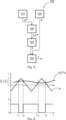
- figure 5 shows schematically and by way of example the sequence of a method 500 for controlling a converter 130, in particular an active rectifier 132', 132", in one embodiment.
- a first step 510 at least one setpoint value S* for converter 130 is specified.
- a signal R for converter 130 is specified in a further step 520 .
- a distortion variable E is then determined in a further step 540 from the setpoint value S* specified in this way and the actual value S recorded in this way.
- a driver signal T for the converter 130, and in particular for the switches of the converter 130, is determined from the distortion quantity E determined in this way and the signal R, for example by adjustment.
- FIG. 6 shows a schematic and exemplary determination of a driver signal T for the converter as a function of the distortion variable E and the carrier signal R.
- the carrier signal T is implemented as described above or below.
- the distortion variable E for example, is adjusted with this carrier signal R in order to generate corresponding driver signals T.
- the amount of distortion E is also set out as described above or below.
- the distortion variable E has an amplitude E and a frequency f E .
- a carrier signal R in the form of a triangle and the distortion quantity E are used.
- the driver signal T is equal to 1 and accordingly a switch of the converter is in position 1, that is, for example, switched on.
- the driver signal T becomes equal to 0 and the corresponding switch of the converter is switched to position 0, that is, for example, switched off.
- the driver signal T becomes equal to 1 and the corresponding switch of the converter is switched to position 1 again.
- the determination of the driver signals T can also be carried out correspondingly with the expanded distortion variable E* described herein or the modulation signal U described herein.
Priority Applications (6)
| Application Number | Priority Date | Filing Date | Title |
|---|---|---|---|
| EP21213468.8A EP4195486A1 (fr) | 2021-12-09 | 2021-12-09 | Procédé de commande d'un redresseur actif d'une éolienne |
| EP22191995.4A EP4195487A1 (fr) | 2021-12-09 | 2022-08-24 | Procédé de commande d'un redresseur actif d'une éolienne |
| EP22191998.8A EP4195488A1 (fr) | 2021-12-09 | 2022-08-24 | Procédé de commande d'un redresseur actif d'une éolienne |
| US18/063,366 US20230188065A1 (en) | 2021-12-09 | 2022-12-08 | Method for controlling an active rectifier of a wind power installation |
| US18/063,371 US20230187943A1 (en) | 2021-12-09 | 2022-12-08 | Method for controlling an active rectifier of a wind power installation |
| US18/063,330 US20230188051A1 (en) | 2021-12-09 | 2022-12-08 | Method for controlling an active rectifier of a wind power installation |
Applications Claiming Priority (1)
| Application Number | Priority Date | Filing Date | Title |
|---|---|---|---|
| EP21213468.8A EP4195486A1 (fr) | 2021-12-09 | 2021-12-09 | Procédé de commande d'un redresseur actif d'une éolienne |
Publications (1)
| Publication Number | Publication Date |
|---|---|
| EP4195486A1 true EP4195486A1 (fr) | 2023-06-14 |
Family
ID=78828053
Family Applications (3)
| Application Number | Title | Priority Date | Filing Date |
|---|---|---|---|
| EP21213468.8A Pending EP4195486A1 (fr) | 2021-12-09 | 2021-12-09 | Procédé de commande d'un redresseur actif d'une éolienne |
| EP22191995.4A Pending EP4195487A1 (fr) | 2021-12-09 | 2022-08-24 | Procédé de commande d'un redresseur actif d'une éolienne |
| EP22191998.8A Pending EP4195488A1 (fr) | 2021-12-09 | 2022-08-24 | Procédé de commande d'un redresseur actif d'une éolienne |
Family Applications After (2)
| Application Number | Title | Priority Date | Filing Date |
|---|---|---|---|
| EP22191995.4A Pending EP4195487A1 (fr) | 2021-12-09 | 2022-08-24 | Procédé de commande d'un redresseur actif d'une éolienne |
| EP22191998.8A Pending EP4195488A1 (fr) | 2021-12-09 | 2022-08-24 | Procédé de commande d'un redresseur actif d'une éolienne |
Country Status (2)
| Country | Link |
|---|---|
| US (3) | US20230188051A1 (fr) |
| EP (3) | EP4195486A1 (fr) |
Citations (3)
| Publication number | Priority date | Publication date | Assignee | Title |
|---|---|---|---|---|
| JPS60187292A (ja) * | 1984-03-07 | 1985-09-24 | Mitsubishi Electric Corp | インバ−タ装置 |
| JPH06351264A (ja) * | 1993-06-03 | 1994-12-22 | Fanuc Ltd | 交流電動機電流制御方式 |
| ES2371845A1 (es) * | 2011-06-09 | 2012-01-10 | Universidad Politécnica de Madrid | Sistema y procedimiento de control de un inversor electrónico como fuente de corriente no lineal. |
Family Cites Families (1)
| Publication number | Priority date | Publication date | Assignee | Title |
|---|---|---|---|---|
| EP3576284A1 (fr) * | 2018-05-30 | 2019-12-04 | Siemens Aktiengesellschaft | Couplage électrique d'un premier réseau électrique avec un second réseau électrique |
-
2021
- 2021-12-09 EP EP21213468.8A patent/EP4195486A1/fr active Pending
-
2022
- 2022-08-24 EP EP22191995.4A patent/EP4195487A1/fr active Pending
- 2022-08-24 EP EP22191998.8A patent/EP4195488A1/fr active Pending
- 2022-12-08 US US18/063,330 patent/US20230188051A1/en active Pending
- 2022-12-08 US US18/063,366 patent/US20230188065A1/en active Pending
- 2022-12-08 US US18/063,371 patent/US20230187943A1/en active Pending
Patent Citations (3)
| Publication number | Priority date | Publication date | Assignee | Title |
|---|---|---|---|---|
| JPS60187292A (ja) * | 1984-03-07 | 1985-09-24 | Mitsubishi Electric Corp | インバ−タ装置 |
| JPH06351264A (ja) * | 1993-06-03 | 1994-12-22 | Fanuc Ltd | 交流電動機電流制御方式 |
| ES2371845A1 (es) * | 2011-06-09 | 2012-01-10 | Universidad Politécnica de Madrid | Sistema y procedimiento de control de un inversor electrónico como fuente de corriente no lineal. |
Also Published As
| Publication number | Publication date |
|---|---|
| EP4195487A1 (fr) | 2023-06-14 |
| US20230188065A1 (en) | 2023-06-15 |
| US20230187943A1 (en) | 2023-06-15 |
| US20230188051A1 (en) | 2023-06-15 |
| EP4195488A1 (fr) | 2023-06-14 |
Similar Documents
| Publication | Publication Date | Title |
|---|---|---|
| EP2955808B1 (fr) | Procédé de régulation d'une éolienne pendant une défaillance réseau asymétrique | |
| EP2614573B1 (fr) | Procédé de stabilisation d'un réseau d'alimentation électrique | |
| DE10330473A1 (de) | Frequenzumwandler für Hochgeschwindigkeitsgeneratoren | |
| EP3275075A1 (fr) | Procédé de commande d'un générateur synchrone d'une éolienne à entraînement direct | |
| DE2225609A1 (de) | Mehrphasiger Wechselstrommotorantrieb mit einstellbarer Drehzahl | |
| EP2971757B1 (fr) | Éolienne à mesure de fréquence | |
| EP2641322A1 (fr) | Système de distribution d'énergie avec convertisseur matriciel multiphase et procédé permettant de le faire fonctionner | |
| WO2018138184A1 (fr) | Procédé pour l'injection d'un courant électrique alternatif | |
| EP1548278B1 (fr) | Installation éolienne avec un dispositif de commande autoalimenté avec un module de régulation de puissance active et puissance réactive | |
| DE102014016664A1 (de) | Verfahren zum Betreiben einer Windenenergieanlage mit komplexer Umrichtersteuerung und Vorrichtung hierfür | |
| EP3735740B1 (fr) | Installation d'énergie éolienne pour injecter d'énergie électrique au moyen d'un convertisseur | |
| EP3516763B1 (fr) | Procédé de production d'un courant alternatif au moyen d'un convertisseur d'une éolienne | |
| EP3890136A1 (fr) | Procédé de fonctionnement d'un convertisseur, en particulier d'une éolienne | |
| EP4195486A1 (fr) | Procédé de commande d'un redresseur actif d'une éolienne | |
| DE19827261C1 (de) | Verfahren und Vorrichtung zur Ausregelung von Leistungsschwankungen eines Generators | |
| WO2005114830A1 (fr) | Dispositif convertisseur de frequence pour parc a energie eolienne et procede pour exploiter un tel dispositif | |
| EP2677622B1 (fr) | Procédé et dispositif d'injection d'une puissance électrique dans un réseau d'alimentation en énergie électrique | |
| EP3852214A1 (fr) | Procédé de commande d'une éolienne | |
| EP3996270A1 (fr) | Méthode de commande destinée à un convertisseur de puissance | |
| EP4156479A1 (fr) | Unité de commande et procédé pour un onduleur | |
| EP4325717A1 (fr) | Procédé de commande d'un convertisseur | |
| DE102010000838A1 (de) | Verfahren und Vorrichtung zum Aufsynchronisieren eines Generators in einem Netz | |
| DE2615744A1 (de) | Verfahren und einrichtung zur steuerung der frequenz und regelung der ausgangsspannung eines zwischenkreis-umrichters zur speisung eines mit veraenderlicher frequenz und drehzahl betriebenen drehstrommotors | |
| EP3993253A1 (fr) | Réglage hysterese d'un courant avec temps morts pour éviter des commutations fausses sous la dependence d'oscillations dans un convertisseur | |
| DE102019106583A1 (de) | Verfahren zur dreiphasigen Einspeisung in ein Wechselspannungsnetz und dreiphasiger Wechselrichter |
Legal Events
| Date | Code | Title | Description |
|---|---|---|---|
| PUAI | Public reference made under article 153(3) epc to a published international application that has entered the european phase |
Free format text: ORIGINAL CODE: 0009012 |
|
| STAA | Information on the status of an ep patent application or granted ep patent |
Free format text: STATUS: THE APPLICATION HAS BEEN PUBLISHED |
|
| AK | Designated contracting states |
Kind code of ref document: A1 Designated state(s): AL AT BE BG CH CY CZ DE DK EE ES FI FR GB GR HR HU IE IS IT LI LT LU LV MC MK MT NL NO PL PT RO RS SE SI SK SM TR |
|
| STAA | Information on the status of an ep patent application or granted ep patent |
Free format text: STATUS: REQUEST FOR EXAMINATION WAS MADE |
|
| 17P | Request for examination filed |
Effective date: 20231214 |
|
| RBV | Designated contracting states (corrected) |
Designated state(s): AL AT BE BG CH CY CZ DE DK EE ES FI FR GB GR HR HU IE IS IT LI LT LU LV MC MK MT NL NO PL PT RO RS SE SI SK SM TR |