EP4195404A1 - Slot antenna in a multi-layered printed circuit board - Google Patents
Slot antenna in a multi-layered printed circuit board Download PDFInfo
- Publication number
- EP4195404A1 EP4195404A1 EP21213788.9A EP21213788A EP4195404A1 EP 4195404 A1 EP4195404 A1 EP 4195404A1 EP 21213788 A EP21213788 A EP 21213788A EP 4195404 A1 EP4195404 A1 EP 4195404A1
- Authority
- EP
- European Patent Office
- Prior art keywords
- antenna
- pcb
- slot
- previous
- ghz
- Prior art date
- Legal status (The legal status is an assumption and is not a legal conclusion. Google has not performed a legal analysis and makes no representation as to the accuracy of the status listed.)
- Pending
Links
- 239000002184 metal Substances 0.000 claims abstract description 11
- 229910052751 metal Inorganic materials 0.000 claims abstract description 11
- 239000000758 substrate Substances 0.000 claims abstract description 5
- 239000010410 layer Substances 0.000 claims description 19
- 230000005540 biological transmission Effects 0.000 claims description 14
- 239000003990 capacitor Substances 0.000 claims description 6
- 239000002356 single layer Substances 0.000 claims description 3
- 238000013461 design Methods 0.000 description 12
- 230000005855 radiation Effects 0.000 description 9
- RYGMFSIKBFXOCR-UHFFFAOYSA-N Copper Chemical compound [Cu] RYGMFSIKBFXOCR-UHFFFAOYSA-N 0.000 description 4
- 238000004891 communication Methods 0.000 description 4
- 229910052802 copper Inorganic materials 0.000 description 4
- 239000010949 copper Substances 0.000 description 4
- 230000010354 integration Effects 0.000 description 4
- 230000005404 monopole Effects 0.000 description 3
- 238000013459 approach Methods 0.000 description 2
- 238000010276 construction Methods 0.000 description 2
- 230000001419 dependent effect Effects 0.000 description 2
- 238000004519 manufacturing process Methods 0.000 description 2
- 238000005457 optimization Methods 0.000 description 2
- 150000003071 polychlorinated biphenyls Chemical class 0.000 description 2
- 238000004458 analytical method Methods 0.000 description 1
- 230000015556 catabolic process Effects 0.000 description 1
- 239000000919 ceramic Substances 0.000 description 1
- 238000006731 degradation reaction Methods 0.000 description 1
- 238000010586 diagram Methods 0.000 description 1
- 239000003989 dielectric material Substances 0.000 description 1
- 238000009826 distribution Methods 0.000 description 1
- 230000005684 electric field Effects 0.000 description 1
- 230000005284 excitation Effects 0.000 description 1
- 238000012986 modification Methods 0.000 description 1
- 230000004048 modification Effects 0.000 description 1
- 230000000704 physical effect Effects 0.000 description 1
- 230000001902 propagating effect Effects 0.000 description 1
Images


Classifications
-
- H—ELECTRICITY
- H01—ELECTRIC ELEMENTS
- H01Q—ANTENNAS, i.e. RADIO AERIALS
- H01Q13/00—Waveguide horns or mouths; Slot antennas; Leaky-waveguide antennas; Equivalent structures causing radiation along the transmission path of a guided wave
- H01Q13/10—Resonant slot antennas
- H01Q13/16—Folded slot antennas
-
- H—ELECTRICITY
- H01—ELECTRIC ELEMENTS
- H01Q—ANTENNAS, i.e. RADIO AERIALS
- H01Q1/00—Details of, or arrangements associated with, antennas
- H01Q1/12—Supports; Mounting means
- H01Q1/22—Supports; Mounting means by structural association with other equipment or articles
- H01Q1/2291—Supports; Mounting means by structural association with other equipment or articles used in bluetooth or WI-FI devices of Wireless Local Area Networks [WLAN]
-
- H—ELECTRICITY
- H01—ELECTRIC ELEMENTS
- H01Q—ANTENNAS, i.e. RADIO AERIALS
- H01Q13/00—Waveguide horns or mouths; Slot antennas; Leaky-waveguide antennas; Equivalent structures causing radiation along the transmission path of a guided wave
- H01Q13/10—Resonant slot antennas
- H01Q13/18—Resonant slot antennas the slot being backed by, or formed in boundary wall of, a resonant cavity ; Open cavity antennas
Definitions
- the present disclosure relates to an antenna developed for the frequency bandwidth between 2.40 and 2.5 GHz, for use in communication systems, namely Bluetooth and Wi-Fi ® , of instrumentation clusters for motorized vehicles.
- Patent [4] proposes a slot structure on the grounding structure of the PCB and a feeding element that crosses over it.
- a similar concept is presented in [5] and [6], where slotted structures created on the grounding planes of the PCB (printed circuit board) are used to create the appropriate resonances of the antennas. The differences lie in the geometrical characteristics of these proposals and the different feeding locations and topologies used.
- [5] proposes rectangular and triangular shaped slots with short lengths
- [6] proposes longer slot lengths with thinner openings.
- [5] proposes a shorted feeding system with reactive elements (e.g. capacitors and/or inductors), in [6] only an extension of a transmission line is proposed with a given length over the slot to provide the correct impedance match.
- [7] extends the application of the slot antennas by applying a second structure to the device in an elevated plane with relation to the slot in order to add a second frequency band of operation to the device.
- [8] extends the application of slot antennas by implementing a second slot and explaining the particularities on the distance between slots and differences in phase of the feeding points to allow both antennas to operate within a single device.
- Chip antennas are usually very compact in size, and reportedly generic in usage so that they can be integrated in any kind of electronic product. But the small size comes with a considerable constraint on the radiation efficiency capability of these antennas. Their generality usually comes at the cost of a layout specification that is enforced during the design of the PCB to make the antenna work properly, which, if not adhered to, largely hinders the antenna performance.
- the slot as referred in [7] is used as part of a multi-band antenna.
- the feeding structure is positioned in the middle of the slotted branch. Also, a second dedicated support structure is required for the other portion of the antenna. That solution is cumbersome and requires a considerable amount of volume inside the device and of clearance on the PCB.
- the implementation referred in [9] is a standalone antenna implementation, which requires a small PCB and a slotted structure is used as radiation mechanism but comprising the whole size of the small PCB. It is intended to be used as a standalone solution that can then be applied on top of other product PCB.
- the solution, as shown, is not suitable to be integrated into a product PCB, given its requirement to have the slot positioned all around the PCB and relying on the openings at the side walls, it can only be used as a standalone solution.
- the slot is used not as the main radiator element but as a tuning aiding structure for an antenna section placed above the slotted ground section on the PCB.
- This patent describes the use of lumped components over a slotted ground plane structure, as can be also done in our design, as well as others presented before.
- the case of the invention reported in [10] is that the slotted structure is used to serve another external antenna as a tuning device and not as the antenna itself.
- the antenna presented in [11] also resorts to a slotted ground plane with a feeding element across the gap, but this antenna is built to be used as a standalone antenna solution and the major drawback is the use of a backplate behind the slot of the antenna. This backplate increases the overall dimensions of the slot and also the overall volume of the antenna.
- the present disclosure relates to an antenna developed for the frequency bandwidth between 2.40 and 2.5 GHz, for use in communication systems, namely Bluetooth and Wi-Fi ® , of instrumentation clusters for motorized vehicles.
- the antenna was developed to create a less expensive solution and improve on the radiation performance of previous generation of products, where ceramic based antennas, commonly referred to as chip antennas, were used.
- One of the purposes of the present disclosure is to develop a PCB integrated antenna, with a design that would increase the radiation performance when compared to the chip antennas, while at the same time maintaining the same or even improve the needed PCB space for the correct implementation of the antenna. Also, by integrating the antenna into the PCB construction we save on cost of acquiring a separate antenna component, making this disclosure a less expensive solution when compared to the chip antennas.
- the present disclosure provides a smaller volume and more flexible solution that allows the antenna to be fitted in a highly populated electronic PCB without causing much constraints to the overall design of the layout, instead of creating a standalone antenna solution.
- the present disclosure is improved using a multi-layer cavity as compared to a single-layer slot as proposed in said patent, which gives more robustness to the manufacturing errors.
- the feeding element is located close to the opening of the slot at the edge of the PCB, instead of the middle, as proposed in [4]. This allowed us to reduce the length of the slot, since we are implementing an image of a monopole antenna, as compared to the image of the dipole as proposed in [4]. This reduces the overall volume needed for the antenna and renders more flexibility in terms of the slot direction, giving freedom to implement any complex geometry instead of being constrained to symmetrical designs.
- the slot as referred in [6] is rather large to accommodate the needed frequency. Plus, the rectangular geometry requires a large portion of the PCB to be allocated to the antenna.
- the embodiment as presented in this disclosure addresses this issue by creating a multi-section slot that has the feeding positions at one open end at the edge of the PCB and using a reactive component over the slot opening. This way we could reduce the length of the overall structure. Also, by constraining the application to single band operation and given the narrow bandwidth needed, we could largely reduce the width of the design as well.
- the slot as referred in [7] is used as part of a multi-band antenna.
- the embodiment presented in this disclosure requires much less space, by creating a multi-section slot that has the feeding positions at one open end at the edge of the PCB and using a reactive component over the slot opening. Also, by constraining the application to single band operation and given the narrow bandwidth needed, we could largely reduce the width of the design as well. Also, since the feeding element is constructed in one of the outer layers of the PCB itself, not increasing the required volume nor requiring supporting elements.
- the slot as referred in [8] is shorter in length, this can be achieved in our embodiment as well at the cost of radiation efficiency, for that reason, the cutout in our embodiment is not recommended to be below 1/10 of the required wavelength in full length when considering the different sections. Also, in [8] the slots are straight, which creates a considerable constraint in PCB layout design. This is solved in our design by introducing bends in the design.
- the antenna presented in [11] also resorts to a slotted ground plane with a feeding element across the gap, but this antenna is built to be used as a standalone antenna solution and the major drawback is the use of a backplate behind the slot of the antenna. Besides, the use of the backplate create a directive antenna with a main direction of radiation, unlike the present disclosure where a nearly omnidirectional solution is required.
- the integration of the antenna in a PCB may also be difficult due to the backplate distance to the slot requirements. This imposes constraints on the PCB characteristics that may be hard to comply.
- one of the main improvement that the embodiment, as described here, provides is to create a smaller volume and more flexible solution that allows the antenna to be fitted in a highly populated electronic PCB without causing much constraints to the overall design of the layout, instead of creating a standalone antenna solution.
- One of the core aspects of this disclosure is the antenna geometry achieved that allows for space saving and flexibility when integrating the antenna into a PCB. This is accomplished by creating a multi-section slot/cavity on the PCB that can be bent with straight or rounded arcs.
- the slotted entry of the antenna is thin with values ranging between 0.5 and 1.5 mm, and the extension of the slot can be constructed with multiple sections even though the best approach is to keep to three sections where the larger section stands parallel to the edge of the PCB. This largely improves layout integration of the antenna and reduces drastically on the space constraints for the antenna integration when compared to other PCB integrated antennas, such as printed or chip antenna solutions.
- This antenna has to be integrated into a multi-layered PCB with minimum of 4-layers, which is a limitation when compared to single layered slot antennas.
- a printed circuit board, PCB, slot antenna comprising: a PCB substrate comprising at least four overlapping metal layers; a feeding element for feeding signal into the antenna; wherein each metal layer comprises an open slot comprising a first straight segment and a second straight segment, with an open end and a close end; wherein the slot is open across all the metal layers; wherein the second segment is connected to the first segment; wherein the open end is located at an edge of PCB for receiving the feeding element; wherein the first and second segments form a tilt angle between each other, wherein the angle is between 10° and 90°. It should be noted that the 90° angle is excluded from this range.
- the PCB slot antenna further comprising a plurality of conductive vias arranged to surround the first straight segment and the second straight segment for connecting ground layers, traversing at least the four metal layers of the PCB substrate.
- the tilt angle is between 45°and 90°.
- the tilt angle is from 45° inclusive and below 90° exclusive.
- the slot further comprises a third straight segment with an additional tilt angle relative to the second straight segment.
- the additional tilt angle is from 45° and below 90°.
- the length of the first segment is 1/23 of a resonant wavelength of the antenna
- the length of the second segment is 1/41 of the resonant wavelength of the antenna
- the length of the third segment is 1/17 of the resonant wavelength of the antenna.
- the PCB slot antenna is configured for a frequency bandwidth between 800MHz and 60 GHz, preferably between 1 GHz and 30 GHz, more preferably between 2 GHz and 6 GHz.
- PCB slot antenna is configured for a frequency bandwidth between preferably 2.300 GHz and 2.600 GHz, preferably between 2,350 GHz and 2,550 GHz, more preferably between 2,400 GHz and 2.482 GHz.
- the feeding element is reactive passive component, in particular the feeding element comprising a transmission line terminated by a capacitor or an inductor or a transmission line extension.
- the transmission line is terminated by a single-layer cut-out perpendicular to the slot, which is formed across the first straight segment.
- the slot has a depth i.e. equal to the PCB depth of more than 0,6 mm, preferably between 0,7 mm and 2,0 mm, more preferably between 0,8 mm and 1,6 mm.
- the length of the slot is 1/8 of a resonant wavelength of the antenna.
- PCB slot antenna is a Bluetooth ® or Wi-Fi ® antenna.
- the antenna here presented is built by creating a keepout zone on the copper layers of the board 1 , all copper planes 2 and signal tracks need the be removed in this section, and surrounding it with through hole vias 3 , therefore creating a cavity with dielectric filling with surrounding conducting walls and an opening at one end.
- the overall length of the slot is approximate to 1/8 of the operation wavelength, which is half of the typical monopole length. This happens due to the structure of the antenna being accomplished with a cavity, with the electric fields propagating at both extremities of the PCB, therefore traveling double the effective distance of the slot which would be equivalent to traveling 1/4 of the wavelength as in a monopole.
- the slot structure is made of two or more sections, with equal or different lengths each. While the overall length changes slightly depending on the number of bends and the length of each section, the largest section should be placed parallel to the PCB edge closest to it, hence the best approach is to keep to three sections.
- the bends can be accomplished in a cut or round shape.
- the lengths of each section are interdependent and need to be found through optimization. The distance between corner point is dependent on the required frequency and overall length of each other sections.
- the length of each section of the slot is therefore, dependent on the target resonating frequency and the size of the other sections. In summary, the correct lengths for each section need to be found through optimization, by establishing the target frequency, the number of bends and the expected start and relative end position of the slot.
- the feeding element 4 of the resonating structure can be accomplished either by extending a section of a transmission line 5 , either short 5 or open terminated 6 , or by placing a lumped component, either a capacitor 7 or inductor 8 , across the slotted section and close to the opening end of the slot.
- the feeding element should be tuned in order to maximize the radiation efficiency, by minimizing the needed matching network elements, between the wireless module and the antenna feeding element.
- Figure 1 shows the PCB integrated slot antenna, formed by creating a keepout area 1 , with a length of approximately 1/8 of the resonant wavelength, in all the conductive layers 2 of the PCB and surrounded by through-hole vias 3 all around.
- the section close to the PCB edge has a length of approximately 1/23 of the resonant wavelength
- the slanted section a length of approximately 1/41 of the resonant wavelength
- the last orthogonal section a length of 1/17 of the resonant wavelength, for a total of 1/8 of the resonant wavelength.
- the slot antenna can be inserted in PCBs with at least four layers. Beyond four-layers there's no significant impact on its operation, so it can be integrated in PCBs with any higher number of layers.
- the excitation element of the antenna structure is accomplished with either a transmission line, that can be terminated in an open or short configuration, as depicted in Figure 2 (a) and (b) , respectively. Or with a lumped element, like a capacitor or inductor, as depicted in Figure 2 (c) and (d) , respectively.
- Figure 3 shows the possible embodiments as for the positioning on the PCB.
- the preferred position is in the middle of the longest size of the PCB, this is the position that allows a better distribution of the radiated field, making it more homogeneous. Nevertheless, the antenna can be positioned anywhere along the edges of the PCB, so long only one narrow end is open.
- the signal is fed to the resonating structure through a transmission line 9 that can encompass a matching network to retune the antenna impedance.
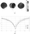
- the radiation pattern is nearly omnidirectional (see Figure7 ), which is the typical requirement for ubiquitous communication services such as Bluetooth and Wi-Fi ® for which this antenna is mainly targeted.
- the overall length of the slot should be approximately 1/8 of the resonant wavelength, but the length and direction of each section, can be changed to better fit the antenna into the product PCB.
- any of the sections can be shortened or lengthened, so long the other sections are re-dimensioned accordingly, to compensate for the overall length, so that it retains the approximate 1/8 of resonant wavelength, as depicted in Figure 4 .
- the directions of the slot sections can have different angles, up to 90o, as depicted in Figure 5 .
- the number of sections can be as low as two, as depicted in Figure 5 (a) and as high as physically possible. The higher the number of sections, the longer the overall slot length needs to be.
- Bandwidth of the antenna is mainly limited by the matching network elements bandwidth.
- the bandwidth is generally between 4 % to 6 %, which is enough to cover Bluetooth and Wi-Fi ® bands at 2.4 GHz (see Figure 8 ). This is better than typicalchip antenna performances where the bandwidth is between 2 % to 3 %, limited mainly by the antenna (see Figure 9 ).
- This invention can be found in devices with wireless communication interfaces, particularly, but not limited to, systems operating at 2.4 GHz band.
- a careful analysis of the PCB of the competitor product must be carried in order to check if the physical properties of the antenna construction are matched.
- the slot/cavity antenna must comprise an opening at a copper edge of the PCB and must be done in all layers so that the slot is only filled with dielectric material from the PCB. Moreover, the walls of the slot should be accomplished with the use of through-hole vias.
- the slotted area should be comprised of more than one section, with cut or curved corners in between, forming angles of 10 to 90o between sections.
- the slot must have a signal track or a lumped component placed across the slot at any position along its length, with the end terminated either in short or open configuration.
- This antenna design can also be integrated into instrumentation clusters with connectivity for motorcycles.
- the antenna can be used for motorcycle integrated connectivity clusters for different OEMs (Original Equipment Manufacturer).
Abstract
Description
- The present disclosure relates to an antenna developed for the frequency bandwidth between 2.40 and 2.5 GHz, for use in communication systems, namely Bluetooth and Wi-Fi®, of instrumentation clusters for motorized vehicles.
- Prior art that is related to the present disclosure as described in this document can be found in scientific publications as well as international patents. Relatable concepts of slot antennas have been presented in scientific publications such as in [1], [2] and [3].
- Besides these scientific publications, concepts with similar nature can also be found in patent works as specified in patents
EP2704252A2 [4],EP3367505A1 [5],US2015263430 [6],US9502773 CN201610200205 - The concepts explored in [4], [7] and [8] are similar, but [7] extends the application of the slot antennas by applying a second structure to the device in an elevated plane with relation to the slot in order to add a second frequency band of operation to the device. While [8] extends the application of slot antennas by implementing a second slot and explaining the particularities on the distance between slots and differences in phase of the feeding points to allow both antennas to operate within a single device.
- Chip antennas are usually very compact in size, and reportedly generic in usage so that they can be integrated in any kind of electronic product. But the small size comes with a considerable constraint on the radiation efficiency capability of these antennas. Their generality usually comes at the cost of a layout specification that is enforced during the design of the PCB to make the antenna work properly, which, if not adhered to, largely hinders the antenna performance.
- The slot as referred in [7] is used as part of a multi-band antenna. The feeding structure is positioned in the middle of the slotted branch. Also, a second dedicated support structure is required for the other portion of the antenna. That solution is cumbersome and requires a considerable amount of volume inside the device and of clearance on the PCB.
- The implementation referred in [9] is a standalone antenna implementation, which requires a small PCB and a slotted structure is used as radiation mechanism but comprising the whole size of the small PCB. It is intended to be used as a standalone solution that can then be applied on top of other product PCB. The solution, as shown, is not suitable to be integrated into a product PCB, given its requirement to have the slot positioned all around the PCB and relying on the openings at the side walls, it can only be used as a standalone solution.
- In [10] the slot is used not as the main radiator element but as a tuning aiding structure for an antenna section placed above the slotted ground section on the PCB. This patent describes the use of lumped components over a slotted ground plane structure, as can be also done in our design, as well as others presented before. However, the case of the invention reported in [10] is that the slotted structure is used to serve another external antenna as a tuning device and not as the antenna itself.
- The antenna presented in [11] also resorts to a slotted ground plane with a feeding element across the gap, but this antenna is built to be used as a standalone antenna solution and the major drawback is the use of a backplate behind the slot of the antenna. This backplate increases the overall dimensions of the slot and also the overall volume of the antenna.
-
- [1] R. Karimian, H. Oraizi, S. Fakhte and M. Farahani, "Novel F-Shaped QuadBand Printed Slot Antenna for WLAN and WiMAX MIMO Systems," in IEEE Antennas and Wireless Propagation Letters, vol. 12, pp. 405-408, 2013, doi: 10.1109/LAWP.2013.2252140.
- [2] W. Hsu, S. Pan and C. Tang, "A Slot MIMO Antenna Design at Small Ground plane for WLAN Application," 2018 15th International Conference on Electrical Engineering/Electronics, Computer, Telecommunications and Information Technology (ECTI-CON), Chiang Rai, Thailand, 2018, pp. 146-149, doi: 10.1109/ECTICon.2018.8620063.
- [3] K. Wong, H. Chang, C. Wang and S. Wang, "Very-Low-Profile Grounded Coplanar Waveguide-Fed Dual-Band WLAN Slot Antenna for On-Body Antenna Application," in IEEE Antennas and Wireless Propagation Letters, vol. 19, no. 1, pp. 213-217, Jan. 2020, doi: 10.1109/LAWP.2019.2958961.
- [4]
Chiu Chien Pin, Tsai Tiao Hsing, Wu Hsiao Wei, Wu Wei Yang, "Mobile Device And Antenna Structure Therein," EP2704252A2 . - [5]
Rutfors Tomas, "Antenna Arrangement and a Device Comprising Such An Antenna Arrangement," EP3367505A1 . - [6]
Chan Ming Che, Lin Chun I, Lin Hui, "Antenna Structure," US2015263430 . - [7]
Chiu Chien Pin, Fang Li Yuan, Kung Yi Hsiang, Tsai Tiao Hsing, Wu Hsiao Wei, "Mobile Device And Manufacturing Method Thereof," US9502773 - [8]
Han Chongzhi, Han Congzhi, "Antenna," CN107293844B . - [9]
Jung Sung, Lee Jae, Kang Sung, Hwang Jung, Kim Yun, Yang Woo, "Slot Antenna Having Slots Formed on Both Sides Of Dielectric Substrate, " US20050057412 A1 . - [10]
Puente Baliarda Carles, Anguera Pros Jaime, "Slotted Ground-Plane Used As A Slot Antenna Or Used For A Pifa Antenna", EP1859508 A1 . - [11]
Taura Toru, "Slot Antenna, Electronic Apparatus, And Method For Manufacturing Slot Antenna, " US2012007783 AA - These facts are disclosed in order to illustrate the technical problem addressed by the present disclosure.
- The present disclosure relates to an antenna developed for the frequency bandwidth between 2.40 and 2.5 GHz, for use in communication systems, namely Bluetooth and Wi-Fi®, of instrumentation clusters for motorized vehicles. The antenna was developed to create a less expensive solution and improve on the radiation performance of previous generation of products, where ceramic based antennas, commonly referred to as chip antennas, were used.
- One of the purposes of the present disclosure is to develop a PCB integrated antenna, with a design that would increase the radiation performance when compared to the chip antennas, while at the same time maintaining the same or even improve the needed PCB space for the correct implementation of the antenna. Also, by integrating the antenna into the PCB construction we save on cost of acquiring a separate antenna component, making this disclosure a less expensive solution when compared to the chip antennas.
- The present disclosure provides a smaller volume and more flexible solution that allows the antenna to be fitted in a highly populated electronic PCB without causing much constraints to the overall design of the layout, instead of creating a standalone antenna solution.
- Compared to patent [4], the present disclosure is improved using a multi-layer cavity as compared to a single-layer slot as proposed in said patent, which gives more robustness to the manufacturing errors. Also, in the embodiment as proposed in this disclosure, the feeding element is located close to the opening of the slot at the edge of the PCB, instead of the middle, as proposed in [4]. This allowed us to reduce the length of the slot, since we are implementing an image of a monopole antenna, as compared to the image of the dipole as proposed in [4]. This reduces the overall volume needed for the antenna and renders more flexibility in terms of the slot direction, giving freedom to implement any complex geometry instead of being constrained to symmetrical designs.
- Compared to patent [5], the present disclosure reported improves on the flexibility of the antenna to adapt to the constraints imposed by mechanical features of our devices, by recurring to a multi-section that can be formed by one, two or more bends to the slotted intrusion, as compared to the square or triangular shaped geometries as proposed in [5].
- The slot as referred in [6] is rather large to accommodate the needed frequency. Plus, the rectangular geometry requires a large portion of the PCB to be allocated to the antenna. The embodiment as presented in this disclosure addresses this issue by creating a multi-section slot that has the feeding positions at one open end at the edge of the PCB and using a reactive component over the slot opening. This way we could reduce the length of the overall structure. Also, by constraining the application to single band operation and given the narrow bandwidth needed, we could largely reduce the width of the design as well.
- The slot as referred in [7] is used as part of a multi-band antenna. The embodiment presented in this disclosure requires much less space, by creating a multi-section slot that has the feeding positions at one open end at the edge of the PCB and using a reactive component over the slot opening. Also, by constraining the application to single band operation and given the narrow bandwidth needed, we could largely reduce the width of the design as well. Also, since the feeding element is constructed in one of the outer layers of the PCB itself, not increasing the required volume nor requiring supporting elements.
- The slot as referred in [8] is shorter in length, this can be achieved in our embodiment as well at the cost of radiation efficiency, for that reason, the cutout in our embodiment is not recommended to be below 1/10 of the required wavelength in full length when considering the different sections. Also, in [8] the slots are straight, which creates a considerable constraint in PCB layout design. This is solved in our design by introducing bends in the design.
- The antenna presented in [11] also resorts to a slotted ground plane with a feeding element across the gap, but this antenna is built to be used as a standalone antenna solution and the major drawback is the use of a backplate behind the slot of the antenna. Besides, the use of the backplate create a directive antenna with a main direction of radiation, unlike the present disclosure where a nearly omnidirectional solution is required. The integration of the antenna in a PCB may also be difficult due to the backplate distance to the slot requirements. This imposes constraints on the PCB characteristics that may be hard to comply.
- Compared to prior art, particularly against [1], [2] and [3], one of the main improvement that the embodiment, as described here, provides is to create a smaller volume and more flexible solution that allows the antenna to be fitted in a highly populated electronic PCB without causing much constraints to the overall design of the layout, instead of creating a standalone antenna solution.
- One of the core aspects of this disclosure is the antenna geometry achieved that allows for space saving and flexibility when integrating the antenna into a PCB. This is accomplished by creating a multi-section slot/cavity on the PCB that can be bent with straight or rounded arcs. The slotted entry of the antenna is thin with values ranging between 0.5 and 1.5 mm, and the extension of the slot can be constructed with multiple sections even though the best approach is to keep to three sections where the larger section stands parallel to the edge of the PCB. This largely improves layout integration of the antenna and reduces drastically on the space constraints for the antenna integration when compared to other PCB integrated antennas, such as printed or chip antenna solutions.
- This antenna has to be integrated into a multi-layered PCB with minimum of 4-layers, which is a limitation when compared to single layered slot antennas. However, when compared to a single layered slot, reduces the deviations that can occur due to manufacturing tolerances and increases the robustness of the structure to the surrounding elements of the antenna, therefore allowing its integration into a highly populated PCB with components or mechanical protrusions (holes and/or screws) in its vicinity, without severe degradation of performance.
- It is disclosed a printed circuit board, PCB, slot antenna, comprising: a PCB substrate comprising at least four overlapping metal layers; a feeding element for feeding signal into the antenna; wherein each metal layer comprises an open slot comprising a first straight segment and a second straight segment, with an open end and a close end; wherein the slot is open across all the metal layers; wherein the second segment is connected to the first segment; wherein the open end is located at an edge of PCB for receiving the feeding element; wherein the first and second segments form a tilt angle between each other, wherein the angle is between 10° and 90°. It should be noted that the 90° angle is excluded from this range.
- In an embodiment, the PCB slot antenna further comprising a plurality of conductive vias arranged to surround the first straight segment and the second straight segment for connecting ground layers, traversing at least the four metal layers of the PCB substrate.
- In an embodiment, the tilt angle is between 45°and 90°.
- In an embodiment, the tilt angle is from 45° inclusive and below 90° exclusive.
- In an embodiment, the slot further comprises a third straight segment with an additional tilt angle relative to the second straight segment.
- In an embodiment, the additional tilt angle is from 45° and below 90°.
- In an embodiment, the length of the first segment is 1/23 of a resonant wavelength of the antenna, the length of the second segment is 1/41 of the resonant wavelength of the antenna, the length of the third segment is 1/17 of the resonant wavelength of the antenna.
- In an embodiment, the PCB slot antenna is configured for a frequency bandwidth between 800MHz and 60 GHz, preferably between 1 GHz and 30 GHz, more preferably between 2 GHz and 6 GHz.
- In an embodiment, PCB slot antenna is configured for a frequency bandwidth between preferably 2.300 GHz and 2.600 GHz, preferably between 2,350 GHz and 2,550 GHz, more preferably between 2,400 GHz and 2.482 GHz.
- In an embodiment, the feeding element is reactive passive component, in particular the feeding element comprising a transmission line terminated by a capacitor or an inductor or a transmission line extension.
- In an embodiment, the transmission line is terminated by a single-layer cut-out perpendicular to the slot, which is formed across the first straight segment.
- In an embodiment, the slot has a depth i.e. equal to the PCB depth of more than 0,6 mm, preferably between 0,7 mm and 2,0 mm, more preferably between 0,8 mm and 1,6 mm.
- In an embodiment, the length of the slot is 1/8 of a resonant wavelength of the antenna.
- In an embodiment, PCB slot antenna is a Bluetooth® or Wi-Fi® antenna.
- The following figures provide preferred embodiments for illustrating the description and should not be seen as limiting the scope of disclosure.
-
Figure 1 shows a schematic representation of an embodiment of the antenna, wherein 2 represents a board and represents all copper planes; 3 represents hole vias; 4 feeding element; 9 represents a transmission line and Y represents an PCB component. -
Figure 2 shows a schematic representation of an embodiment of the antenna, wherein 5 represents a short transmission line; 6 represents an open terminated transmission line; 7 represents a capacitor; 8 represents an inductor and 9 represents a transmission line. -
Figure 3 shows a schematic representation of an embodiment of an antenna element and related details according to this disclosure with different dimensions. -
Figure 4 shows a schematic representation of different embodiments wherein the first and second segments form a tilt angle between each other with different angles between 10° and 90° and wherein the slot further comprises a third straight segment with an additional tilt angle relative to the second straight segment. -
Figure 5 shows a schematic representation of an embodiment wherein: (a) represents the first and second segments form a tilt angle with 90° between each other; and (b) and (c) represents different embodiments wherein the first, second and third segments form a tilt angle and an additional tilt angle. -
Figure 6 shows a schematic representation of an embodiment wherein: A represents long side center position; B represents a long side side position and C represents a short side center position. -
Figure 7 shows a schematic representation of a radiation diagram of an embodiment of the slot antenna. -
Figure 8 shows a schematic representation of an embodiment, wherein: A represents long side center position; B represents a long side side position and C represents a short side center position. -
Figure 9 shows a schematic representation of an embodiment, wherein: A represents chip antenna and B represents a slot antenna. - The antenna here presented is built by creating a keepout zone on the copper layers of the
board 1, allcopper planes 2 and signal tracks need the be removed in this section, and surrounding it with throughhole vias 3, therefore creating a cavity with dielectric filling with surrounding conducting walls and an opening at one end. - The overall length of the slot is approximate to 1/8 of the operation wavelength, which is half of the typical monopole length. This happens due to the structure of the antenna being accomplished with a cavity, with the electric fields propagating at both extremities of the PCB, therefore traveling double the effective distance of the slot which would be equivalent to traveling 1/4 of the wavelength as in a monopole.
- The slot structure is made of two or more sections, with equal or different lengths each. While the overall length changes slightly depending on the number of bends and the length of each section, the largest section should be placed parallel to the PCB edge closest to it, hence the best approach is to keep to three sections. The bends can be accomplished in a cut or round shape. The lengths of each section are interdependent and need to be found through optimization. The distance between corner point is dependent on the required frequency and overall length of each other sections. The length of each section of the slot, is therefore, dependent on the target resonating frequency and the size of the other sections. In summary, the correct lengths for each section need to be found through optimization, by establishing the target frequency, the number of bends and the expected start and relative end position of the slot.
- The
feeding element 4 of the resonating structure can be accomplished either by extending a section of atransmission line 5, either short 5 or open terminated 6, or by placing a lumped component, either acapacitor 7 orinductor 8, across the slotted section and close to the opening end of the slot. The feeding element should be tuned in order to maximize the radiation efficiency, by minimizing the needed matching network elements, between the wireless module and the antenna feeding element. -
Figure 1 shows the PCB integrated slot antenna, formed by creating akeepout area 1, with a length of approximately 1/8 of the resonant wavelength, in all theconductive layers 2 of the PCB and surrounded by through-hole vias 3 all around. In the first embodiment of the antenna, the section close to the PCB edge has a length of approximately 1/23 of the resonant wavelength, the slanted section a length of approximately 1/41 of the resonant wavelength and the last orthogonal section a length of 1/17 of the resonant wavelength, for a total of 1/8 of the resonant wavelength. - The slot antenna can be inserted in PCBs with at least four layers. Beyond four-layers there's no significant impact on its operation, so it can be integrated in PCBs with any higher number of layers.
- The excitation element of the antenna structure is accomplished with either a transmission line, that can be terminated in an open or short configuration, as depicted in
Figure 2 (a) and (b) , respectively. Or with a lumped element, like a capacitor or inductor, as depicted inFigure 2 (c) and (d) , respectively. -
Figure 3 shows the possible embodiments as for the positioning on the PCB. The preferred position is in the middle of the longest size of the PCB, this is the position that allows a better distribution of the radiated field, making it more homogeneous. Nevertheless, the antenna can be positioned anywhere along the edges of the PCB, so long only one narrow end is open. - The signal is fed to the resonating structure through a
transmission line 9 that can encompass a matching network to retune the antenna impedance. Typical efficiencies in excess of 75% when standalone in a PCB with dimensions bigger than 100x50mm, regardless of the position, be it the longest or shortest side of the PCB (seeFigures 3 and6 ). Which is unlike the typical chip antenna where the efficiency is largely affected by the PCB size and location where it is placed. - The radiation pattern is nearly omnidirectional (see
Figure7 ), which is the typical requirement for ubiquitous communication services such as Bluetooth and Wi-Fi® for which this antenna is mainly targeted. - The overall length of the slot should be approximately 1/8 of the resonant wavelength, but the length and direction of each section, can be changed to better fit the antenna into the product PCB. Hence any of the sections can be shortened or lengthened, so long the other sections are re-dimensioned accordingly, to compensate for the overall length, so that it retains the approximate 1/8 of resonant wavelength, as depicted in
Figure 4 . - As well, the directions of the slot sections can have different angles, up to 90º, as depicted in
Figure 5 . The number of sections can be as low as two, as depicted inFigure 5 (a) and as high as physically possible. The higher the number of sections, the longer the overall slot length needs to be. - Bandwidth of the antenna is mainly limited by the matching network elements bandwidth. With typical use of SMD components, with 0402 or 0201 package, the bandwidth is generally between 4 % to 6 %, which is enough to cover Bluetooth and Wi-Fi® bands at 2.4 GHz (see
Figure 8 ). This is better than typicalchip antenna performances where the bandwidth is between 2 % to 3 %, limited mainly by the antenna (seeFigure 9 ). - This invention can be found in devices with wireless communication interfaces, particularly, but not limited to, systems operating at 2.4 GHz band. In order to confirm this invention is being used under a competitor product a careful analysis of the PCB of the competitor product must be carried in order to check if the physical properties of the antenna construction are matched.
- The slot/cavity antenna must comprise an opening at a copper edge of the PCB and must be done in all layers so that the slot is only filled with dielectric material from the PCB. Moreover, the walls of the slot should be accomplished with the use of through-hole vias. The slotted area should be comprised of more than one section, with cut or curved corners in between, forming angles of 10 to 90º between sections.
- The slot must have a signal track or a lumped component placed across the slot at any position along its length, with the end terminated either in short or open configuration.
- This antenna design can also be integrated into instrumentation clusters with connectivity for motorcycles. In particular, the antenna can be used for motorcycle integrated connectivity clusters for different OEMs (Original Equipment Manufacturer).
- The term "comprising" whenever used in this document is intended to indicate the presence of stated features, integers, steps, components, but not to preclude the presence or addition of one or more other features, integers, steps, components or groups thereof.
- It will be appreciated by those of ordinary skill in the art that unless otherwise indicated herein, the particular sequence of steps described is illustrative only and can be varied without departing from the disclosure. Thus, unless otherwise stated the steps described are so unordered meaning that, when possible, the steps can be performed in any convenient or desirable order.
- The disclosure should not be seen in any way restricted to the embodiments described and a person with ordinary skill in the art will foresee many possibilities to modifications thereof. The above described embodiments are combinable. The following claims further set out particular embodiments of the disclosure.
Claims (14)
- Printed circuit board, PCB, slot antenna (1), comprising:a PCB substrate (2) comprising at least four overlapping metal layers;a feeding element (4, 5, 6, 7, 8) for feeding signal into the antenna;wherein each metal layer comprises an open slot comprising a first straight segment and a second straight segment, with an open end and a close end;wherein the slot is open across all the metal layers;wherein the second segment is connected to the first segment;wherein the open end is located at an edge of PCB for receiving the feeding element (4,5,6,7,8);wherein the first and second segments form a tilt angle between each other, wherein the angle is between 10° and 90°.
- PCB slot antenna (1) according to the previous claim further comprising a plurality of conductive vias (3) arranged to surround the first straight segment and the second straight segment for connecting ground layers, traversing all the metal layers of the PCB substrate.
- PCB slot antenna (1) according any of the previous claims, wherein the tilt angle is between 45°and 90°.
- PCB slot antenna (1) according to any of the previous claims, wherein the tilt angle is from 45° inclusive and below 90° exclusive.
- PCB slot antenna (1) according to any of the previous claims, wherein the slot further comprises a third straight segment with an additional tilt angle relative to the second straight segment.
- PCB slot antenna (1) according to the previous claim wherein the additional tilt angle is from 45° and below 90°.
- PCB slot antenna (1) according to any of the previous claims wherein the length of the first segment is 1/23 of a resonant wavelength of the antenna, the length of the second segment is 1/41 of the resonant wavelength of the antenna, the length of the third segment is 1/17 of the resonant wavelength of the antenna.
- PCB slot antenna (1) according to any of the previous claims, wherein said antenna is configured for a frequency bandwidth between 800MHz and 60 GHz, preferably between 1 GHz and 30 GHz, more preferably between 2 GHz and 6 GHz.
- PCB slot antenna (1) according to any of the previous claims, wherein said antenna is configured for a frequency bandwidth between preferably 2.30 GHz and 2.60 GHz, preferably between 2,35 GHz and 2,55 GHz, more preferably 2,4 GHz.
- PCB slot antenna (1) according to any of the previous claims, wherein the feeding element (4,5,6,7,8) is a reactive passive component, in particular the feeding element (4,5,6,7,8) comprising a transmission line (9) terminated by a capacitor or an inductor or a transmission line extension.
- PCB slot antenna (1) according to the previous claim, wherein the transmission line (9) is terminated by a single-layer cut-out perpendicular to the slot, which is formed across the first straight segment.
- PCB slot antenna (1) according to any of the previous claims, wherein the slot has a depth of more than 0,6 mm, preferably between 0,7 mm and 2,0 mm, more preferably between 0,8 mm and 1,6 mm.
- PCB slot antenna (1) according to any of the previous claims wherein the length of the slot is 1/8 of a resonant wavelength of the antenna.
- PCB slot antenna (1) according to any of the previous claims wherein the antenna is a Bluetooth® or Wi-Fi® antenna.
Priority Applications (1)
| Application Number | Priority Date | Filing Date | Title |
|---|---|---|---|
| EP21213788.9A EP4195404A1 (en) | 2021-12-10 | 2021-12-10 | Slot antenna in a multi-layered printed circuit board |
Applications Claiming Priority (1)
| Application Number | Priority Date | Filing Date | Title |
|---|---|---|---|
| EP21213788.9A EP4195404A1 (en) | 2021-12-10 | 2021-12-10 | Slot antenna in a multi-layered printed circuit board |
Publications (1)
| Publication Number | Publication Date |
|---|---|
| EP4195404A1 true EP4195404A1 (en) | 2023-06-14 |
Family
ID=78829619
Family Applications (1)
| Application Number | Title | Priority Date | Filing Date |
|---|---|---|---|
| EP21213788.9A Pending EP4195404A1 (en) | 2021-12-10 | 2021-12-10 | Slot antenna in a multi-layered printed circuit board |
Country Status (1)
| Country | Link |
|---|---|
| EP (1) | EP4195404A1 (en) |
Citations (13)
| Publication number | Priority date | Publication date | Assignee | Title |
|---|---|---|---|---|
| US6314273B1 (en) * | 1997-09-11 | 2001-11-06 | Mitsubishi Denki Kabushiki Kaisha | Mobile telecommunication apparatus having notches |
| US20050057412A1 (en) | 2003-08-27 | 2005-03-17 | Hwang Jung Hwan | Slot antenna having slots formed on both sides of dielectric substrate |
| EP1859508A1 (en) | 2005-03-15 | 2007-11-28 | Fractus, S.A. | Slotted ground-plane used as a slot antenna or used for a pifa antenna. |
| US20080074332A1 (en) * | 2004-09-21 | 2008-03-27 | Arronte Alfonso S | Multilevel Ground-Plane for a Mobile Device |
| US20120007783A1 (en) | 2009-03-30 | 2012-01-12 | Toru Taura | Slot antenna, electronic apparatus, and method for manufacturing slot antenna |
| JP2012085262A (en) * | 2010-09-16 | 2012-04-26 | Nec Corp | Antenna apparatus |
| US20130257668A1 (en) * | 2012-03-30 | 2013-10-03 | Htc Corporation | Mobile device and antenna array thereof |
| EP2704252A2 (en) | 2012-08-29 | 2014-03-05 | HTC Corporation | Mobile device and antenna structure |
| US20150263430A1 (en) | 2014-03-17 | 2015-09-17 | Quanta Computer Inc. | Antenna structure |
| US9502773B2 (en) | 2015-03-24 | 2016-11-22 | Htc Corporation | Mobile device and manufacturing method thereof |
| CN107293844A (en) | 2016-03-31 | 2017-10-24 | 宇龙计算机通信科技(深圳)有限公司 | A kind of antenna |
| US20180205133A1 (en) * | 2017-01-17 | 2018-07-19 | Kabushiki Kaisha Toshiba | Wireless device |
| EP3367505A1 (en) | 2017-02-27 | 2018-08-29 | ProAnt AB | Antenna arrangement and a device comprising such an antenna arrangement |
-
2021
- 2021-12-10 EP EP21213788.9A patent/EP4195404A1/en active Pending
Patent Citations (13)
| Publication number | Priority date | Publication date | Assignee | Title |
|---|---|---|---|---|
| US6314273B1 (en) * | 1997-09-11 | 2001-11-06 | Mitsubishi Denki Kabushiki Kaisha | Mobile telecommunication apparatus having notches |
| US20050057412A1 (en) | 2003-08-27 | 2005-03-17 | Hwang Jung Hwan | Slot antenna having slots formed on both sides of dielectric substrate |
| US20080074332A1 (en) * | 2004-09-21 | 2008-03-27 | Arronte Alfonso S | Multilevel Ground-Plane for a Mobile Device |
| EP1859508A1 (en) | 2005-03-15 | 2007-11-28 | Fractus, S.A. | Slotted ground-plane used as a slot antenna or used for a pifa antenna. |
| US20120007783A1 (en) | 2009-03-30 | 2012-01-12 | Toru Taura | Slot antenna, electronic apparatus, and method for manufacturing slot antenna |
| JP2012085262A (en) * | 2010-09-16 | 2012-04-26 | Nec Corp | Antenna apparatus |
| US20130257668A1 (en) * | 2012-03-30 | 2013-10-03 | Htc Corporation | Mobile device and antenna array thereof |
| EP2704252A2 (en) | 2012-08-29 | 2014-03-05 | HTC Corporation | Mobile device and antenna structure |
| US20150263430A1 (en) | 2014-03-17 | 2015-09-17 | Quanta Computer Inc. | Antenna structure |
| US9502773B2 (en) | 2015-03-24 | 2016-11-22 | Htc Corporation | Mobile device and manufacturing method thereof |
| CN107293844A (en) | 2016-03-31 | 2017-10-24 | 宇龙计算机通信科技(深圳)有限公司 | A kind of antenna |
| US20180205133A1 (en) * | 2017-01-17 | 2018-07-19 | Kabushiki Kaisha Toshiba | Wireless device |
| EP3367505A1 (en) | 2017-02-27 | 2018-08-29 | ProAnt AB | Antenna arrangement and a device comprising such an antenna arrangement |
Non-Patent Citations (3)
| Title |
|---|
| K. WONGH. CHANGC. WANGS. WANG: "Very-Low-Profile Grounded Coplanar Waveguide-Fed Dual-Band WLAN Slot Antenna for On-Body Antenna Application", IEEE ANTENNAS AND WIRELESS PROPAGATION LETTERS, vol. 19, no. 1, January 2020 (2020-01-01), pages 213 - 217, XP011767919, DOI: 10.1109/LAWP.2019.2958961 |
| R. KARIMIANH. ORAIZIS. FAKHTEM. FARAHANI: "Novel F-Shaped QuadBand Printed Slot Antenna for WLAN and WiMAX MIMO Systems", IEEE ANTENNAS AND WIRELESS PROPAGATION LETTERS, vol. 12, 2013, pages 405 - 408, XP011499524, DOI: 10.1109/LAWP.2013.2252140 |
| W. HSUS. PANC. TANG: "A Slot MIMO Antenna Design at Small Ground plane for WLAN Application", 2018 15TH INTERNATIONAL CONFERENCE ON ELECTRICAL ENGINEERING/ELECTRONICS, COMPUTER, TELECOMMUNICATIONS AND INFORMATION TECHNOLOGY (ECTI-CON), CHIANG RAI, THAILAND, 2018, pages 146 - 149, XP033504696, DOI: 10.1109/ECTICon.2018.8620063 |
Similar Documents
| Publication | Publication Date | Title |
|---|---|---|
| KR101128656B1 (en) | Multi frequency magnetic dipole antenna structures and methods of reusing the volume of an antenna | |
| CN100517863C (en) | Broadband internal antenna | |
| EP2065972B1 (en) | Dual-band-antenna | |
| EP2040329A2 (en) | Antenna device and electronic apparatus | |
| EP2555320B1 (en) | Communication electronic device and antenna structure therein | |
| CN101055940B (en) | Antenna device and multiple frequency band type radio communication device using the same | |
| KR20010020104A (en) | Asymmetric dipole antenna assembly | |
| JP2004201278A (en) | Pattern antenna | |
| KR20020029310A (en) | Small antenna | |
| JP2003163528A (en) | Printed circuit board, smd antenna, and communication equipment | |
| CN101116222A (en) | Internal monopole antenna | |
| JP2004088218A (en) | Planar antenna | |
| JP2002299933A (en) | Electrode structure for antenna and communication equipment provided with the same | |
| JP2003188624A (en) | Directional antenna | |
| JP3930477B2 (en) | Dielectric antenna | |
| CN114530694B (en) | Wireless communication structure, display panel and wireless communication device | |
| CN112886194A (en) | Antenna structure | |
| US7598912B2 (en) | Planar antenna structure | |
| US20110221638A1 (en) | Internal lc antenna for wireless communication device | |
| CN102986086A (en) | Antenna having planar conducting elements | |
| EP4195404A1 (en) | Slot antenna in a multi-layered printed circuit board | |
| CN114566783A (en) | Antenna module and electronic device | |
| US8570234B2 (en) | Assembly of chip antenna and circuit board | |
| EP2341578A1 (en) | Chip antenna | |
| CN113964518A (en) | Antenna device and electronic equipment |
Legal Events
| Date | Code | Title | Description |
|---|---|---|---|
| PUAI | Public reference made under article 153(3) epc to a published international application that has entered the european phase |
Free format text: ORIGINAL CODE: 0009012 |
|
| STAA | Information on the status of an ep patent application or granted ep patent |
Free format text: STATUS: THE APPLICATION HAS BEEN PUBLISHED |
|
| AK | Designated contracting states |
Kind code of ref document: A1 Designated state(s): AL AT BE BG CH CY CZ DE DK EE ES FI FR GB GR HR HU IE IS IT LI LT LU LV MC MK MT NL NO PL PT RO RS SE SI SK SM TR |
|
| STAA | Information on the status of an ep patent application or granted ep patent |
Free format text: STATUS: REQUEST FOR EXAMINATION WAS MADE |
|
| 17P | Request for examination filed |
Effective date: 20231214 |
|
| RBV | Designated contracting states (corrected) |
Designated state(s): AL AT BE BG CH CY CZ DE DK EE ES FI FR GB GR HR HU IE IS IT LI LT LU LV MC MK MT NL NO PL PT RO RS SE SI SK SM TR |