EP4195340A1 - Mandrel for manufacturing electrode assembly of cylindrical secondary battery - Google Patents
Mandrel for manufacturing electrode assembly of cylindrical secondary battery Download PDFInfo
- Publication number
- EP4195340A1 EP4195340A1 EP21854490.6A EP21854490A EP4195340A1 EP 4195340 A1 EP4195340 A1 EP 4195340A1 EP 21854490 A EP21854490 A EP 21854490A EP 4195340 A1 EP4195340 A1 EP 4195340A1
- Authority
- EP
- European Patent Office
- Prior art keywords
- mandrel
- electrode assembly
- manufacturing
- protrusion
- concave
- Prior art date
- Legal status (The legal status is an assumption and is not a legal conclusion. Google has not performed a legal analysis and makes no representation as to the accuracy of the status listed.)
- Granted
Links
Images


Classifications
-
- H—ELECTRICITY
- H01—ELECTRIC ELEMENTS
- H01M—PROCESSES OR MEANS, e.g. BATTERIES, FOR THE DIRECT CONVERSION OF CHEMICAL ENERGY INTO ELECTRICAL ENERGY
- H01M10/00—Secondary cells; Manufacture thereof
- H01M10/04—Construction or manufacture in general
-
- H—ELECTRICITY
- H01—ELECTRIC ELEMENTS
- H01M—PROCESSES OR MEANS, e.g. BATTERIES, FOR THE DIRECT CONVERSION OF CHEMICAL ENERGY INTO ELECTRICAL ENERGY
- H01M10/00—Secondary cells; Manufacture thereof
- H01M10/04—Construction or manufacture in general
- H01M10/0404—Machines for assembling batteries
- H01M10/0409—Machines for assembling batteries for cells with wound electrodes
-
- H—ELECTRICITY
- H01—ELECTRIC ELEMENTS
- H01M—PROCESSES OR MEANS, e.g. BATTERIES, FOR THE DIRECT CONVERSION OF CHEMICAL ENERGY INTO ELECTRICAL ENERGY
- H01M10/00—Secondary cells; Manufacture thereof
- H01M10/04—Construction or manufacture in general
- H01M10/0431—Cells with wound or folded electrodes
-
- H—ELECTRICITY
- H01—ELECTRIC ELEMENTS
- H01M—PROCESSES OR MEANS, e.g. BATTERIES, FOR THE DIRECT CONVERSION OF CHEMICAL ENERGY INTO ELECTRICAL ENERGY
- H01M10/00—Secondary cells; Manufacture thereof
- H01M10/05—Accumulators with non-aqueous electrolyte
- H01M10/058—Construction or manufacture
- H01M10/0587—Construction or manufacture of accumulators having only wound construction elements, i.e. wound positive electrodes, wound negative electrodes and wound separators
-
- H—ELECTRICITY
- H01—ELECTRIC ELEMENTS
- H01M—PROCESSES OR MEANS, e.g. BATTERIES, FOR THE DIRECT CONVERSION OF CHEMICAL ENERGY INTO ELECTRICAL ENERGY
- H01M10/00—Secondary cells; Manufacture thereof
- H01M10/04—Construction or manufacture in general
- H01M10/0422—Cells or battery with cylindrical casing
-
- Y—GENERAL TAGGING OF NEW TECHNOLOGICAL DEVELOPMENTS; GENERAL TAGGING OF CROSS-SECTIONAL TECHNOLOGIES SPANNING OVER SEVERAL SECTIONS OF THE IPC; TECHNICAL SUBJECTS COVERED BY FORMER USPC CROSS-REFERENCE ART COLLECTIONS [XRACs] AND DIGESTS
- Y02—TECHNOLOGIES OR APPLICATIONS FOR MITIGATION OR ADAPTATION AGAINST CLIMATE CHANGE
- Y02E—REDUCTION OF GREENHOUSE GAS [GHG] EMISSIONS, RELATED TO ENERGY GENERATION, TRANSMISSION OR DISTRIBUTION
- Y02E60/00—Enabling technologies; Technologies with a potential or indirect contribution to GHG emissions mitigation
- Y02E60/10—Energy storage using batteries
-
- Y—GENERAL TAGGING OF NEW TECHNOLOGICAL DEVELOPMENTS; GENERAL TAGGING OF CROSS-SECTIONAL TECHNOLOGIES SPANNING OVER SEVERAL SECTIONS OF THE IPC; TECHNICAL SUBJECTS COVERED BY FORMER USPC CROSS-REFERENCE ART COLLECTIONS [XRACs] AND DIGESTS
- Y02—TECHNOLOGIES OR APPLICATIONS FOR MITIGATION OR ADAPTATION AGAINST CLIMATE CHANGE
- Y02P—CLIMATE CHANGE MITIGATION TECHNOLOGIES IN THE PRODUCTION OR PROCESSING OF GOODS
- Y02P70/00—Climate change mitigation technologies in the production process for final industrial or consumer products
- Y02P70/50—Manufacturing or production processes characterised by the final manufactured product
Definitions
- the present invention relates to a mandrel for manufacturing an electrode assembly, which may be minimally deformed when used for a winding process at the time of manufacturing an electrode assembly for a cylindrical secondary battery.
- an electrode assembly for a cylindrical secondary battery is manufactured in a jelly-roll shape by being wound around a mandrel.
- a mandrel is fitted into an end of a stack of positive electrodes, separators, and negative electrodes, the electrode assembly is made by winding the stack in a cylindrical shape around the mandrel, and then the mandrel is removed from the electrode assembly.
- Korean Patent Application Laid-Open No. 10-2009-0037552 (published on April 16, 2009 ) discloses a mandrel for manufacturing an electrode assembly for a secondary battery.
- a mandrel 10 for manufacturing an electrode assembly in the related art has a cylindrical shape as a pair of first and second mandrel members 11 and 12 each having a semicircular circumference is coupled to face each other. Further, a separator disposed at an end of a sheet-type stack is interposed between joint surfaces of the first and second mandrel members 11 and 12.
- One side of the mandrel 10 including the first and second mandrel members 11 and 12 is coupled to a support member 20, and a tail center 30 is disposed on the same horizontal line as the other side of the mandrel 10.
- Ajelly-roll type electrode assembly 1 is wound around an outer circumference of the mandrel 10 structured as described above.
- the electrode assembly 1 is easily separated from the mandrel 10 as the first and second mandrel members 11 and 12 are sequentially moved rearward in a longitudinal direction by an operation of an actuator (not illustrated).
- a capacity of a battery may increase as a diameter of the mandrel 10 for manufacturing the electrode assembly 1 decreases.
- a diameter of the mandrel 10 for manufacturing the electrode assembly 1 decreases.
- mechanical properties deteriorate, and a strain rate of the mandrel 10 increases.
- the strain rate of the mandrel further increases when a small-caliber mandrel, which has a diameter of 3.0 mm smaller than a diameter of 3.4 mm of the mandrel 10 in the related art, is applied. For this reason, there is a problem in that the mandrel may be damaged by colliding with the tail center before the tail center is inserted into the mandrel as the mandrel is moved forward.
- first and second mandrel members 11 and 12 of the mandrel 10 in the related art which have the symmetric structure, may be designed asymmetrically to prevent deformation of the mandrel 10.
- the present invention has been made in an effort to solve the above-mentioned problems, and an object of the present invention is to provide a mandrel for manufacturing an electrode assembly, which may be minimally deformed even though the mandrel having a caliber smaller than that of a mandrel in the related art is used for a winding process at the time of manufacturing an electrode assembly for a cylindrical secondary battery.
- a mandrel for manufacturing an electrode assembly for a cylindrical secondary battery includes: a first mandrel member having a semicircular cross-section and a predetermined length; and a second mandrel member configured to define a cylindrical shape by being coupled to the first mandrel member while facing the first mandrel member, in which a concave-convex part is provided on joint surfaces of the first and second mandrel members and includes a protrusion and a groove formed in a longitudinal direction so as to engage with each other.
- two opposite sides in the longitudinal direction of each of the first and second mandrel members may be asymmetrically formed.
- joint surfaces of the first and second mandrel members may be inclined at 0 to 1° in the longitudinal direction.
- the concave-convex part may be formed on the remaining joint surface except for a section in which an end of a stack constituting the electrode assembly is interposed.
- one or more concave-convex parts may be formed.
- the protrusion and the groove may each have a quadrangular cross-section.
- a width and a height of the protrusion may be 50% or less of a diameter of the mandrel.
- an edge of the protrusion may be rounded by 0.01 to 0.5 mm.
- two opposite surfaces in a width direction of the protrusion may be inclined at 80 to 100° with respect to the joint surface.
- the one or more protrusions and the one or more grooves are formed on the joint surfaces of the first and second mandrel members so as to engage with one another. Therefore, it is possible to minimize the deformation of the mandrel even though the mandrel having a caliber smaller than the caliber of the mandrel in the related art is used for the winding process at the time of manufacturing the electrode assembly for a cylindrical secondary battery.
- Electrode assembly 20 Support member 30: Tail center 100: Mandrel for manufacturing electrode assembly 110: First mandrel member 120: Second mandrel member 130: Concave-convex part 131: Protrusion 133: Groove
- FIG. 2 is an exploded perspective view of a mandrel for manufacturing an electrode assembly according to the present invention
- FIG. 3 is a cross-sectional plan view of the mandrel for manufacturing an electrode assembly according to the present invention.
- a mandrel 100 for manufacturing an electrode assembly may include: a first mandrel member 110 having a semicircular cross-section and a predetermined length; and a second mandrel member 120 configured to define a cylindrical shape by being coupled to the first mandrel member 110 while facing the first mandrel member 110.
- a concave-convex part 130 is provided on joint surfaces of the first and second mandrel members 110 and 120 and includes protrusions 131 and grooves 133 formed in a longitudinal direction so as to engage with one another.
- the mandrel 100 for manufacturing an electrode assembly according to the present invention may have a cylindrical shape as the pair of first and second mandrel members 110 and 120 each having a semicircular circumference is coupled to face each other.
- one side of the mandrel 100 including the first and second mandrel members 110 and 120 may be coupled to a support member 20, and a tail center 30 (see FIG. 1 ) may be disposed on the same horizontal line as the other side of the mandrel 100.
- An end (separator) of a sheet-type stack may be interposed between the joint surfaces of the first and second mandrel members 110 and 120 of the mandrel 100 structured as described above. Further, an electrode assembly 1 may be formed by being wound in a jelly-roll shape around an outer circumference of the mandrel 100.
- the electrode assembly 1 may be easily separated from the mandrel 100 as the first and second mandrel members 110 and 120 are sequentially moved rearward in a longitudinal direction by an operation of an actuator (not illustrated).
- two opposite sides in the longitudinal direction of the first and second mandrel members 110 and 120 may have an asymmetric structure to reduce a strain rate of the mandrel 100.
- the joint surfaces of the first and second mandrel members 110 and 120 may be inclined at 0 to 1° along the two opposite sides in the longitudinal direction.
- a volume of a comparatively large mandrel member of the first and second mandrel members 110 and 120 may be 50 to 60%, and a volume of a comparatively small mandrel member of the first and second mandrel members 110 and 120 may be 40 to 50%. If the volume of the small mandrel member is 40% or less, a strain rate of the small mandrel member may increase.
- the concave-convex part 130 includes the protrusions 131 and the grooves 133 formed in the longitudinal direction on the joint surfaces of the first and second mandrel members 110 and 120 so as to engage with one another.
- the protrusions 131 and the grooves 133, which constitute the concave-convex part 130, may each have a quadrangular cross-section.
- two opposite surfaces in a width direction of the protruding protrusion 131 may be inclined at 80 to 100° with respect to the joint surface. That is, if an angle of each of the two opposite surfaces in the width direction of the protrusion 131 is less than 80° or more than 100°, the strain rate of the mandrel 100 may increase.
- a width and a height of the protrusion 131 may be equal to or less than 50% of a diameter of the mandrel 100. That is, if the width and the height of the protrusion 131 is equal to or more than 50% of the diameter of the mandrel 100, there is concern that the protrusion 131 may be deformed and the separator interposed between the joint surfaces may be damaged.
- an edge of the protrusion 131 may be rounded by 0.01 to 0.5 mm. Further, an inner edge portion of the protrusion 131 corresponding to the groove 133 coupled to the protrusion 131 may also be rounded. That is, if the edge round of the protrusion 131 is less than 0.01 mm, the separator may be damaged. On the contrary, if the edge round of the protrusion 131 is more than 0.5 mm, the strain rate of the mandrel 100 may increase.
- the concave-convex part 130 structured as described above may be formed on the remaining joint surfaces except for sections in which the separator, which is the end of the stack constituting the electrode assembly 1, is interposed (see FIG. 3 ). That is, if the concave-convex part 130 is formed on the entire joint surfaces of the mandrel 100, there is concern that the separator may be caught or damaged by the first and second mandrel members 110 and 120 when the first and second mandrel members 110 and 120 are moved forward and rearward to separate the electrode assembly 1 from the mandrel 100.
- one or more concave-convex parts 130 may be formed.
- at least two concave-convex parts 130 may be disposed to be spaced apart from one another side by side.
- the concave-convex part 130 formed on the joint surfaces of the mandrel 100 having a diameter (mm) of ⁇ 3.0 may have various structures.
- Example 1 the single protrusion 131 and the single groove 133 are formed on the joint surfaces of the first and second mandrel members 110 and 120 so as to correspond to each other.
- an angle of the protrusion 131 is 90°
- an edge round R of the protrusion 131 is 0.1 mm.
- Example 2 the protrusions 131 and the grooves 133 are formed in two rows on the joint surfaces of the first and second mandrel members 110 and 120 so as to correspond to one another.
- a width of each of the protrusion 131 and the groove 133 in Example 2 is smaller by about 50% than that in Example 1.
- an angle of the protrusion 131 is 90°
- an edge round R of the protrusion 131 is 0.05 mm.
- Example 3 the protrusion 131 and the groove 133 are formed at positions opposite to the positions of the protrusion 131 and the groove 133 in Example 1.
- an angle of the protrusion 131 is 90°
- an edge round R of the protrusion 131 is 0.1 mm.
- Comparative Examples 1 to 3 illustrated in (b) of FIG. 6 show that no concave-convex part 130 according to the present invention is provided.
- Comparative Example 1 has a structure in which the concave-convex part 130 disclosed in Example 1 is omitted from a joint surface of a mandrel 100'.
- an angle of each of the two opposite sides of the joint surface of the mandrel 100' is 60° with respect to an imaginary vertical line in the drawing, and a round R of an edge protruding upward from the joint surface is 0.1 mm.
- the joint surface of the mandrel 100' is curved in an S shape, and a round R of the edge protruding upward or downward from the joint surface is 1 mm.
- Example 1 Example 2
- Angle of concave-convex part 90 90 90 0 60
- Round of concave-convex part 0.1 0.05 0.1 0 0.1 1 ⁇ 3.0
- the deformation of the mandrel 100 in Example 2 which has the two protrusions 131 formed side by side on the first mandrel member 110, is 0.083 mm and thus smaller than the deformation of the mandrels in Examples 1 and 3.
- the one or more protrusions 131 and the one or more grooves 133 are formed on the joint surfaces of the first and second mandrel members 110 and 120 so as to engage with one another. Therefore, it is possible to minimize the deformation of the mandrel even though the mandrel having a caliber ( ⁇ 3.0) smaller than the caliber of the mandrel 10 in the related art is used for the winding process at the time of manufacturing the electrode assembly 1 for a cylindrical secondary battery.
Landscapes
- Engineering & Computer Science (AREA)
- Manufacturing & Machinery (AREA)
- Chemical & Material Sciences (AREA)
- Chemical Kinetics & Catalysis (AREA)
- Electrochemistry (AREA)
- General Chemical & Material Sciences (AREA)
- Secondary Cells (AREA)
- Battery Electrode And Active Subsutance (AREA)
Abstract
Description
- This application claims priority to and the benefit of
Korean Patent Application No. 10-2020-0097211 filed with the Korean Intellectual Property Office on August 4, 2020 - The present invention relates to a mandrel for manufacturing an electrode assembly, which may be minimally deformed when used for a winding process at the time of manufacturing an electrode assembly for a cylindrical secondary battery.
- In general, an electrode assembly for a cylindrical secondary battery is manufactured in a jelly-roll shape by being wound around a mandrel.
- Specifically, during a process of manufacturing such a jelly-roll type electrode assembly, a mandrel is fitted into an end of a stack of positive electrodes, separators, and negative electrodes, the electrode assembly is made by winding the stack in a cylindrical shape around the mandrel, and then the mandrel is removed from the electrode assembly.
- In the related art,
Korean Patent Application Laid-Open No. 10-2009-0037552 (published on April 16, 2009 - Specifically, referring to
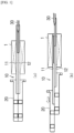
FIG. 1 , amandrel 10 for manufacturing an electrode assembly in the related art has a cylindrical shape as a pair of first andsecond mandrel members second mandrel members - One side of the
mandrel 10 including the first andsecond mandrel members support member 20, and atail center 30 is disposed on the same horizontal line as the other side of themandrel 10. Ajelly-rolltype electrode assembly 1 is wound around an outer circumference of themandrel 10 structured as described above. - After the
electrode assembly 1 is completely manufactured, theelectrode assembly 1 is easily separated from themandrel 10 as the first andsecond mandrel members - Meanwhile, a capacity of a battery may increase as a diameter of the
mandrel 10 for manufacturing theelectrode assembly 1 decreases. However, when the diameter of themandrel 10 decreases, mechanical properties deteriorate, and a strain rate of themandrel 10 increases. - For example, the strain rate of the mandrel further increases when a small-caliber mandrel, which has a diameter of 3.0 mm smaller than a diameter of 3.4 mm of the
mandrel 10 in the related art, is applied. For this reason, there is a problem in that the mandrel may be damaged by colliding with the tail center before the tail center is inserted into the mandrel as the mandrel is moved forward. - In addition, the first and
second mandrel members mandrel 10 in the related art, which have the symmetric structure, may be designed asymmetrically to prevent deformation of themandrel 10. - However, because the small-caliber mandrel is greatly deformed, it is difficult to minimize the deformation of the mandrel having the asymmetric structure in the related art. Accordingly, there is a need to improve a shape of the small-caliber mandrel.
- The present invention has been made in an effort to solve the above-mentioned problems, and an object of the present invention is to provide a mandrel for manufacturing an electrode assembly, which may be minimally deformed even though the mandrel having a caliber smaller than that of a mandrel in the related art is used for a winding process at the time of manufacturing an electrode assembly for a cylindrical secondary battery.
- To achieve the above-mentioned object, a mandrel for manufacturing an electrode assembly for a cylindrical secondary battery according to the present invention includes: a first mandrel member having a semicircular cross-section and a predetermined length; and a second mandrel member configured to define a cylindrical shape by being coupled to the first mandrel member while facing the first mandrel member, in which a concave-convex part is provided on joint surfaces of the first and second mandrel members and includes a protrusion and a groove formed in a longitudinal direction so as to engage with each other.
- In this case, two opposite sides in the longitudinal direction of each of the first and second mandrel members may be asymmetrically formed.
- In addition, the joint surfaces of the first and second mandrel members may be inclined at 0 to 1° in the longitudinal direction.
- In addition, the concave-convex part may be formed on the remaining joint surface except for a section in which an end of a stack constituting the electrode assembly is interposed.
- In addition, one or more concave-convex parts may be formed.
- In addition, the protrusion and the groove may each have a quadrangular cross-section.
- In addition, a width and a height of the protrusion may be 50% or less of a diameter of the mandrel.
- In addition, an edge of the protrusion may be rounded by 0.01 to 0.5 mm.
- In addition, two opposite surfaces in a width direction of the protrusion may be inclined at 80 to 100° with respect to the joint surface.
- According to the mandrel for manufacturing an electrode assembly for a cylindrical secondary battery according to the present invention described above, the one or more protrusions and the one or more grooves are formed on the joint surfaces of the first and second mandrel members so as to engage with one another. Therefore, it is possible to minimize the deformation of the mandrel even though the mandrel having a caliber smaller than the caliber of the mandrel in the related art is used for the winding process at the time of manufacturing the electrode assembly for a cylindrical secondary battery.
-
- (a) of
FIG. 1 and (b) ofFIG. 1 are views illustrating a mandrel for manufacturing an electrode assembly in the related art. -
FIG. 2 is an exploded perspective view of the mandrel for manufacturing an electrode assembly according to the present invention. -
FIG. 3 is a cross-sectional plan view of the mandrel for manufacturing an electrode assembly according to the present invention. -
FIG. 4 is a front view of the mandrel for manufacturing an electrode assembly according to the present invention. -
FIG. 5 is a cross-sectional view taken along line I-I' inFIG. 3 . -
FIG. 6 is a view illustrating various examples and comparative examples of concave-convex parts according to the present invention. - 1: Electrode assembly 20: Support member 30: Tail center 100: Mandrel for manufacturing electrode assembly 110: First mandrel member 120: Second mandrel member 130: Concave-convex part 131: Protrusion 133: Groove
- Hereinafter, configurations and operations of specific embodiments of the present invention will be described in detail with reference to the accompanying drawings.
- In giving reference numerals to constituent elements of the respective drawings, it should be noted that the same constituent elements will be designated by the same reference numerals, if possible, even though the constituent elements are illustrated in different drawings.
-
FIG. 2 is an exploded perspective view of a mandrel for manufacturing an electrode assembly according to the present invention, andFIG. 3 is a cross-sectional plan view of the mandrel for manufacturing an electrode assembly according to the present invention. - Referring to
FIG. 2 , amandrel 100 for manufacturing an electrode assembly according to an exemplary embodiment of the present invention may include: afirst mandrel member 110 having a semicircular cross-section and a predetermined length; and asecond mandrel member 120 configured to define a cylindrical shape by being coupled to thefirst mandrel member 110 while facing thefirst mandrel member 110. A concave-convex part 130 is provided on joint surfaces of the first andsecond mandrel members protrusions 131 andgrooves 133 formed in a longitudinal direction so as to engage with one another. - The configuration of the present invention will be specifically described below.
- First, the
mandrel 100 for manufacturing an electrode assembly according to the present invention may have a cylindrical shape as the pair of first andsecond mandrel members - Referring to
FIG. 3 , one side of themandrel 100 including the first andsecond mandrel members support member 20, and a tail center 30 (seeFIG. 1 ) may be disposed on the same horizontal line as the other side of themandrel 100. - An end (separator) of a sheet-type stack may be interposed between the joint surfaces of the first and
second mandrel members mandrel 100 structured as described above. Further, anelectrode assembly 1 may be formed by being wound in a jelly-roll shape around an outer circumference of themandrel 100. - After the
electrode assembly 1 is completely manufactured, theelectrode assembly 1 may be easily separated from themandrel 100 as the first andsecond mandrel members - Referring to
FIG. 4 , two opposite sides in the longitudinal direction of the first andsecond mandrel members mandrel 100. Specifically, the joint surfaces of the first andsecond mandrel members - That is, a volume of a comparatively large mandrel member of the first and
second mandrel members second mandrel members - Referring to
FIG. 5 , the concave-convex part 130 includes theprotrusions 131 and thegrooves 133 formed in the longitudinal direction on the joint surfaces of the first andsecond mandrel members protrusions 131 and thegrooves 133, which constitute the concave-convex part 130, may each have a quadrangular cross-section. - In this case, two opposite surfaces in a width direction of the
protruding protrusion 131 may be inclined at 80 to 100° with respect to the joint surface. That is, if an angle of each of the two opposite surfaces in the width direction of theprotrusion 131 is less than 80° or more than 100°, the strain rate of themandrel 100 may increase. - Further, a width and a height of the
protrusion 131 may be equal to or less than 50% of a diameter of themandrel 100. That is, if the width and the height of theprotrusion 131 is equal to or more than 50% of the diameter of themandrel 100, there is concern that theprotrusion 131 may be deformed and the separator interposed between the joint surfaces may be damaged. - In addition, an edge of the
protrusion 131 may be rounded by 0.01 to 0.5 mm. Further, an inner edge portion of theprotrusion 131 corresponding to thegroove 133 coupled to theprotrusion 131 may also be rounded. That is, if the edge round of theprotrusion 131 is less than 0.01 mm, the separator may be damaged. On the contrary, if the edge round of theprotrusion 131 is more than 0.5 mm, the strain rate of themandrel 100 may increase. - The concave-
convex part 130 structured as described above may be formed on the remaining joint surfaces except for sections in which the separator, which is the end of the stack constituting theelectrode assembly 1, is interposed (seeFIG. 3 ). That is, if the concave-convex part 130 is formed on the entire joint surfaces of themandrel 100, there is concern that the separator may be caught or damaged by the first andsecond mandrel members second mandrel members electrode assembly 1 from themandrel 100. - In addition, one or more concave-
convex parts 130 may be formed. In particular, at least two concave-convex parts 130 may be disposed to be spaced apart from one another side by side. - As in Examples 1 to 3 illustrated in (a) of
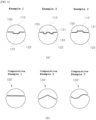
FIG. 6 , the concave-convex part 130 formed on the joint surfaces of themandrel 100 having a diameter (mm) of Φ3.0 may have various structures. - Specifically, in Example 1, the
single protrusion 131 and thesingle groove 133 are formed on the joint surfaces of the first andsecond mandrel members protrusion 131 is 90°, and an edge round R of theprotrusion 131 is 0.1 mm. - In Example 2, the
protrusions 131 and thegrooves 133 are formed in two rows on the joint surfaces of the first andsecond mandrel members protrusion 131 and thegroove 133 in Example 2 is smaller by about 50% than that in Example 1. Further, an angle of theprotrusion 131 is 90°, and an edge round R of theprotrusion 131 is 0.05 mm. - In Example 3, the
protrusion 131 and thegroove 133 are formed at positions opposite to the positions of theprotrusion 131 and thegroove 133 in Example 1. In this case, an angle of theprotrusion 131 is 90°, and an edge round R of theprotrusion 131 is 0.1 mm. - Comparative Examples 1 to 3 illustrated in (b) of
FIG. 6 show that no concave-convex part 130 according to the present invention is provided. - Specifically, Comparative Example 1 has a structure in which the concave-
convex part 130 disclosed in Example 1 is omitted from a joint surface of a mandrel 100'. - In Comparative Example 2, an angle of each of the two opposite sides of the joint surface of the mandrel 100' is 60° with respect to an imaginary vertical line in the drawing, and a round R of an edge protruding upward from the joint surface is 0.1 mm.
- In Comparative Example 3, the joint surface of the mandrel 100' is curved in an S shape, and a round R of the edge protruding upward or downward from the joint surface is 1 mm.
- The following Table 1 shows result results in respect to strain rates of the
mandrels 100 and 100' formed in the shapes in Examples 1 to 3 and Comparative Examples 1 to 3.[Table 1] Example 1 Example 2 Example 3 Comparati ve Example 1 Comparati ve Example 2 Comparativ e Example 3 Number of concave- convex parts 1 2 1 0 1 1 Angle of concave-convex part 90 90 90 0 60 90 Round of concave-convex part 0.1 0.05 0.1 0 0.1 1 Φ3.0 Deformation of mandrel (mm) 0.087 0.083 0.089 0.127 0.147 0.126 - According to the test results shown in Table 1 in respect to the deformation of the mandrels, it can be seen that the deformation of the
mandrel 100 having the concave-convex part 130 according to Examples 1 to 3 is smaller than the deformation of the mandrel 100' according to Comparative Examples 1 to 3. - In particular, it can be seen that, among Examples 1 to 3, the deformation of the
mandrel 100 in Example 2, which has the twoprotrusions 131 formed side by side on thefirst mandrel member 110, is 0.083 mm and thus smaller than the deformation of the mandrels in Examples 1 and 3. - According to the
mandrel 100 for manufacturing an electrode assembly for a cylindrical secondary battery according to the present invention described above, the one ormore protrusions 131 and the one ormore grooves 133 are formed on the joint surfaces of the first andsecond mandrel members mandrel 10 in the related art is used for the winding process at the time of manufacturing theelectrode assembly 1 for a cylindrical secondary battery. - While the present invention has been illustrated and described with reference to the particular specific embodiments, the present invention is not limited to the embodiments, and various alterations and modifications may be made without departing from the technical spirit of the present invention.
Claims (9)
- A mandrel for manufacturing an electrode assembly, the mandrel comprising:a first mandrel member having a semicircular cross-section and a predetermined length; anda second mandrel member configured to define a cylindrical shape by being coupled to the first mandrel member while facing the first mandrel member,wherein a concave-convex part is provided on joint surfaces of the first and second mandrel members and comprises a protrusion and a groove formed in a longitudinal direction so as to engage with each other.
- The mandrel for manufacturing an electrode assembly of claim 1, wherein two opposite sides in the longitudinal direction of each of the first and second mandrel members are asymmetrically formed.
- The mandrel for manufacturing an electrode assembly of claim 2, wherein the joint surfaces of the first and second mandrel members are inclined at 0 to 1° in the longitudinal direction.
- The mandrel for manufacturing an electrode assembly of claim 1, wherein the concave-convex part is formed on the remaining joint surface except for a section in which an end of a stack constituting the electrode assembly is interposed.
- The mandrel for manufacturing an electrode assembly of claim 1, wherein one or more concave-convex parts are formed.
- The mandrel for manufacturing an electrode assembly of claim 1, wherein the protrusion and the groove each have a quadrangular cross-section.
- The mandrel for manufacturing an electrode assembly of claim 6, wherein a width and a height of the protrusion are 50% or less of a diameter of the mandrel.
- The mandrel for manufacturing an electrode assembly of claim 6, wherein an edge of the protrusion is rounded by 0.01 to 0.5 mm.
- The mandrel for manufacturing an electrode assembly of claim 6, wherein two opposite surfaces in a width direction of the protrusion are inclined at 80 to 100° with respect to the joint surface.
Applications Claiming Priority (2)
| Application Number | Priority Date | Filing Date | Title |
|---|---|---|---|
| KR1020200097211A KR102827368B1 (en) | 2020-08-04 | 2020-08-04 | Mandrel structure for fabricating electrode assembly of cylindrical secondary battery |
| PCT/KR2021/010272 WO2022031037A1 (en) | 2020-08-04 | 2021-08-04 | Mandrel for manufacturing electrode assembly of cylindrical secondary battery |
Publications (3)
| Publication Number | Publication Date |
|---|---|
| EP4195340A1 true EP4195340A1 (en) | 2023-06-14 |
| EP4195340A4 EP4195340A4 (en) | 2024-08-14 |
| EP4195340B1 EP4195340B1 (en) | 2025-10-01 |
Family
ID=80118265
Family Applications (1)
| Application Number | Title | Priority Date | Filing Date |
|---|---|---|---|
| EP21854490.6A Active EP4195340B1 (en) | 2020-08-04 | 2021-08-04 | Mandrel for manufacturing electrode assembly of cylindrical secondary battery |
Country Status (7)
| Country | Link |
|---|---|
| US (1) | US20230275254A1 (en) |
| EP (1) | EP4195340B1 (en) |
| JP (1) | JP7549768B2 (en) |
| KR (1) | KR102827368B1 (en) |
| CN (1) | CN116508186A (en) |
| ES (1) | ES3057551T3 (en) |
| WO (1) | WO2022031037A1 (en) |
Cited By (1)
| Publication number | Priority date | Publication date | Assignee | Title |
|---|---|---|---|---|
| EP4503214A1 (en) * | 2023-08-02 | 2025-02-05 | Lee, Kye-seol | Core for winding secondary battery separator film |
Families Citing this family (4)
| Publication number | Priority date | Publication date | Assignee | Title |
|---|---|---|---|---|
| EP4443579B1 (en) * | 2022-07-27 | 2026-05-06 | Contemporary Amperex Technology (Hong Kong) Limited | Winding needle assembly and winding device |
| KR102931978B1 (en) * | 2022-11-01 | 2026-03-03 | 삼성에스디아이 주식회사 | Winding member and secondary battery comprising an electrode assembly manufactured thereby |
| JP2025541511A (en) * | 2022-12-26 | 2025-12-18 | エルジー エナジー ソリューション リミテッド | Winding core for electrode assembly, cylindrical battery cell produced using the same, battery pack including the cylindrical battery cell, and automobile |
| US20250290582A1 (en) * | 2024-03-18 | 2025-09-18 | Jayson Dumenigo | Lockout Shaft |
Family Cites Families (19)
| Publication number | Priority date | Publication date | Assignee | Title |
|---|---|---|---|---|
| JPS62147661A (en) * | 1985-12-23 | 1987-07-01 | Sanyo Electric Co Ltd | Manufacturing method of spiral electrode body |
| US4975095A (en) * | 1989-07-28 | 1990-12-04 | Gates Energy Products, Inc. | Method of winding an electrochemical cell and cell produced by the method |
| JP3379282B2 (en) * | 1995-05-22 | 2003-02-24 | 松下電器産業株式会社 | Apparatus and method for producing battery electrode body |
| JP3475010B2 (en) * | 1996-05-30 | 2003-12-08 | 三洋電機株式会社 | Spiral electrode body manufacturing apparatus and spiral electrode body manufacturing method |
| JP2000331704A (en) * | 1999-05-24 | 2000-11-30 | Toshiba Battery Co Ltd | Manufacturing device for wound electrode |
| JP2001068144A (en) | 1999-08-27 | 2001-03-16 | Toshiba Battery Co Ltd | Manufacturing device of rolled electrode |
| US6670071B2 (en) * | 2002-01-15 | 2003-12-30 | Quallion Llc | Electric storage battery construction and method of manufacture |
| JP4498010B2 (en) * | 2004-05-26 | 2010-07-07 | パナソニック株式会社 | Method for manufacturing cylindrical wound electrode body |
| JP4600926B2 (en) | 2005-04-04 | 2010-12-22 | 日立マクセル株式会社 | Winding core and method for producing electrode body using the winding core |
| JP2006290615A (en) | 2005-04-13 | 2006-10-26 | Riyoukoushiya:Kk | Winding core for winder |
| JP2006302799A (en) * | 2005-04-25 | 2006-11-02 | Matsushita Electric Ind Co Ltd | Apparatus for manufacturing cylindrical battery electrode body |
| KR101147604B1 (en) | 2007-10-12 | 2012-05-23 | 주식회사 엘지화학 | Preparation Process for Preventing Deformation of Jelly-roll Type Electrode Assembly |
| JP5274089B2 (en) * | 2008-04-15 | 2013-08-28 | 株式会社皆藤製作所 | Asymmetrical core |
| JP5409338B2 (en) * | 2009-12-25 | 2014-02-05 | 日立ビークルエナジー株式会社 | Winding type square battery |
| KR101685745B1 (en) * | 2013-09-30 | 2016-12-12 | 주식회사 엘지화학 | Mandrel clamp |
| KR101738728B1 (en) * | 2014-01-28 | 2017-05-22 | 주식회사 엘지화학 | Winding device |
| KR102499324B1 (en) * | 2015-10-30 | 2023-02-13 | 삼성에스디아이 주식회사 | Rolling Device for Secondary Battery |
| JP6998186B2 (en) * | 2017-11-22 | 2022-02-04 | Ckd株式会社 | Winding device, sheet winding method and winding element manufacturing method |
| DE102019102874A1 (en) | 2019-02-06 | 2020-08-06 | Man Energy Solutions Se | Turbocharger with a casing and internal combustion engine |
-
2020
- 2020-08-04 KR KR1020200097211A patent/KR102827368B1/en active Active
-
2021
- 2021-08-04 WO PCT/KR2021/010272 patent/WO2022031037A1/en not_active Ceased
- 2021-08-04 CN CN202180049983.6A patent/CN116508186A/en active Pending
- 2021-08-04 US US18/019,706 patent/US20230275254A1/en active Pending
- 2021-08-04 JP JP2023501908A patent/JP7549768B2/en active Active
- 2021-08-04 EP EP21854490.6A patent/EP4195340B1/en active Active
- 2021-08-04 ES ES21854490T patent/ES3057551T3/en active Active
Cited By (1)
| Publication number | Priority date | Publication date | Assignee | Title |
|---|---|---|---|---|
| EP4503214A1 (en) * | 2023-08-02 | 2025-02-05 | Lee, Kye-seol | Core for winding secondary battery separator film |
Also Published As
| Publication number | Publication date |
|---|---|
| WO2022031037A1 (en) | 2022-02-10 |
| EP4195340B1 (en) | 2025-10-01 |
| JP2023534798A (en) | 2023-08-14 |
| EP4195340A4 (en) | 2024-08-14 |
| US20230275254A1 (en) | 2023-08-31 |
| JP7549768B2 (en) | 2024-09-12 |
| KR20220017115A (en) | 2022-02-11 |
| KR102827368B1 (en) | 2025-07-02 |
| ES3057551T3 (en) | 2026-03-03 |
| CN116508186A (en) | 2023-07-28 |
Similar Documents
| Publication | Publication Date | Title |
|---|---|---|
| EP4195340B1 (en) | Mandrel for manufacturing electrode assembly of cylindrical secondary battery | |
| US9899707B2 (en) | Rolling device for secondary battery | |
| JP7746530B2 (en) | Prismatic secondary battery including stacked cells | |
| EP3579299B1 (en) | Battery module | |
| EP4342623A1 (en) | Electrode manufacturing device used for laser notching of electrode | |
| US20250041960A1 (en) | Apparatus for Welding Electrode Tabs and Method for Welding Electrode Tabs | |
| WO2025020512A1 (en) | Battery | |
| JP2019506728A (en) | Battery module having strap type frame and frame assembly therefor | |
| US20230373152A1 (en) | Pouch Shaping Apparatus Capable of Remedying Pouch Wrinkles | |
| US11145868B2 (en) | Electrode piece, cell and energy storage device | |
| US20250337093A1 (en) | Cell casing for a battery cell body | |
| KR20200134672A (en) | Jelly-roll type electrode assembly and secondary battery including the same | |
| KR102790608B1 (en) | Electrode assembly comprising Electrode Tab having uneven surface, Guide member for stacking the electrode assembly, Method of making stacked type battery using the guide member and Stacked type battery manufactured therefrom | |
| KR102928372B1 (en) | Secondary battery and battery module including the same | |
| KR102242250B1 (en) | method of manufacturing electrode assembly and device of pressing electrode assembly | |
| KR102534990B1 (en) | Winding device | |
| KR102500240B1 (en) | Method of manufacturing electrode assembly | |
| KR102180847B1 (en) | Electrode, electrode assembly including the electrode and method of manufacturing the electrode and the electrode assembly | |
| KR20230032989A (en) | Electrode driving roller and notching device comprising the same | |
| US11552282B2 (en) | Roll press apparatus comprising stepped revision member and method for pressing using the same | |
| CN219497986U (en) | Battery pack and battery device | |
| KR102177256B1 (en) | Bending revision device of electrode | |
| CN217009235U (en) | Bipolar plate and fuel cell | |
| EP4254531A1 (en) | Electrode driving roller and notching apparatus comprising same | |
| KR20110012565A (en) | Prefabricated case of circular cross section and its use method |
Legal Events
| Date | Code | Title | Description |
|---|---|---|---|
| STAA | Information on the status of an ep patent application or granted ep patent |
Free format text: STATUS: THE INTERNATIONAL PUBLICATION HAS BEEN MADE |
|
| PUAI | Public reference made under article 153(3) epc to a published international application that has entered the european phase |
Free format text: ORIGINAL CODE: 0009012 |
|
| STAA | Information on the status of an ep patent application or granted ep patent |
Free format text: STATUS: REQUEST FOR EXAMINATION WAS MADE |
|
| 17P | Request for examination filed |
Effective date: 20230208 |
|
| AK | Designated contracting states |
Kind code of ref document: A1 Designated state(s): AL AT BE BG CH CY CZ DE DK EE ES FI FR GB GR HR HU IE IS IT LI LT LU LV MC MK MT NL NO PL PT RO RS SE SI SK SM TR |
|
| DAV | Request for validation of the european patent (deleted) | ||
| DAX | Request for extension of the european patent (deleted) | ||
| A4 | Supplementary search report drawn up and despatched |
Effective date: 20240715 |
|
| RIC1 | Information provided on ipc code assigned before grant |
Ipc: H01M 10/04 20060101AFI20240709BHEP |
|
| GRAP | Despatch of communication of intention to grant a patent |
Free format text: ORIGINAL CODE: EPIDOSNIGR1 |
|
| STAA | Information on the status of an ep patent application or granted ep patent |
Free format text: STATUS: GRANT OF PATENT IS INTENDED |
|
| INTG | Intention to grant announced |
Effective date: 20250512 |
|
| GRAS | Grant fee paid |
Free format text: ORIGINAL CODE: EPIDOSNIGR3 |
|
| GRAA | (expected) grant |
Free format text: ORIGINAL CODE: 0009210 |
|
| STAA | Information on the status of an ep patent application or granted ep patent |
Free format text: STATUS: THE PATENT HAS BEEN GRANTED |
|
| AK | Designated contracting states |
Kind code of ref document: B1 Designated state(s): AL AT BE BG CH CY CZ DE DK EE ES FI FR GB GR HR HU IE IS IT LI LT LU LV MC MK MT NL NO PL PT RO RS SE SI SK SM TR |
|
| REG | Reference to a national code |
Ref country code: GB Ref legal event code: FG4D Ref country code: CH Ref legal event code: F10 Free format text: ST27 STATUS EVENT CODE: U-0-0-F10-F00 (AS PROVIDED BY THE NATIONAL OFFICE) Effective date: 20251001 |
|
| REG | Reference to a national code |
Ref country code: IE Ref legal event code: FG4D |
|
| REG | Reference to a national code |
Ref country code: DE Ref legal event code: R096 Ref document number: 602021039746 Country of ref document: DE |
|
| P01 | Opt-out of the competence of the unified patent court (upc) registered |
Free format text: CASE NUMBER: UPC_APP_8599_4195340/2025 Effective date: 20251001 |
|
| REG | Reference to a national code |
Ref country code: NL Ref legal event code: MP Effective date: 20251001 |
|
| REG | Reference to a national code |
Ref country code: ES Ref legal event code: FG2A Ref document number: 3057551 Country of ref document: ES Kind code of ref document: T3 Effective date: 20260303 |
|
| REG | Reference to a national code |
Ref country code: AT Ref legal event code: MK05 Ref document number: 1843494 Country of ref document: AT Kind code of ref document: T Effective date: 20251001 |
|
| PG25 | Lapsed in a contracting state [announced via postgrant information from national office to epo] |
Ref country code: NL Free format text: LAPSE BECAUSE OF FAILURE TO SUBMIT A TRANSLATION OF THE DESCRIPTION OR TO PAY THE FEE WITHIN THE PRESCRIBED TIME-LIMIT Effective date: 20251001 |
|
| REG | Reference to a national code |
Ref country code: LT Ref legal event code: MG9D |
|
| PG25 | Lapsed in a contracting state [announced via postgrant information from national office to epo] |
Ref country code: NO Free format text: LAPSE BECAUSE OF FAILURE TO SUBMIT A TRANSLATION OF THE DESCRIPTION OR TO PAY THE FEE WITHIN THE PRESCRIBED TIME-LIMIT Effective date: 20260101 |
|
| PG25 | Lapsed in a contracting state [announced via postgrant information from national office to epo] |
Ref country code: HR Free format text: LAPSE BECAUSE OF FAILURE TO SUBMIT A TRANSLATION OF THE DESCRIPTION OR TO PAY THE FEE WITHIN THE PRESCRIBED TIME-LIMIT Effective date: 20251001 Ref country code: AT Free format text: LAPSE BECAUSE OF FAILURE TO SUBMIT A TRANSLATION OF THE DESCRIPTION OR TO PAY THE FEE WITHIN THE PRESCRIBED TIME-LIMIT Effective date: 20251001 Ref country code: FI Free format text: LAPSE BECAUSE OF FAILURE TO SUBMIT A TRANSLATION OF THE DESCRIPTION OR TO PAY THE FEE WITHIN THE PRESCRIBED TIME-LIMIT Effective date: 20251001 |
|
| PG25 | Lapsed in a contracting state [announced via postgrant information from national office to epo] |
Ref country code: RS Free format text: LAPSE BECAUSE OF FAILURE TO SUBMIT A TRANSLATION OF THE DESCRIPTION OR TO PAY THE FEE WITHIN THE PRESCRIBED TIME-LIMIT Effective date: 20260101 |
|
| PG25 | Lapsed in a contracting state [announced via postgrant information from national office to epo] |
Ref country code: IS Free format text: LAPSE BECAUSE OF FAILURE TO SUBMIT A TRANSLATION OF THE DESCRIPTION OR TO PAY THE FEE WITHIN THE PRESCRIBED TIME-LIMIT Effective date: 20260201 |
|
| PG25 | Lapsed in a contracting state [announced via postgrant information from national office to epo] |
Ref country code: CZ Free format text: LAPSE BECAUSE OF FAILURE TO SUBMIT A TRANSLATION OF THE DESCRIPTION OR TO PAY THE FEE WITHIN THE PRESCRIBED TIME-LIMIT Effective date: 20251001 Ref country code: PT Free format text: LAPSE BECAUSE OF FAILURE TO SUBMIT A TRANSLATION OF THE DESCRIPTION OR TO PAY THE FEE WITHIN THE PRESCRIBED TIME-LIMIT Effective date: 20260202 |
|
| PG25 | Lapsed in a contracting state [announced via postgrant information from national office to epo] |
Ref country code: PL Free format text: LAPSE BECAUSE OF FAILURE TO SUBMIT A TRANSLATION OF THE DESCRIPTION OR TO PAY THE FEE WITHIN THE PRESCRIBED TIME-LIMIT Effective date: 20251001 |
|
| PG25 | Lapsed in a contracting state [announced via postgrant information from national office to epo] |
Ref country code: LV Free format text: LAPSE BECAUSE OF FAILURE TO SUBMIT A TRANSLATION OF THE DESCRIPTION OR TO PAY THE FEE WITHIN THE PRESCRIBED TIME-LIMIT Effective date: 20251001 |