EP4194988A1 - System and method for generating work plan for autonomous operation of a compactor - Google Patents
System and method for generating work plan for autonomous operation of a compactor Download PDFInfo
- Publication number
- EP4194988A1 EP4194988A1 EP22207933.7A EP22207933A EP4194988A1 EP 4194988 A1 EP4194988 A1 EP 4194988A1 EP 22207933 A EP22207933 A EP 22207933A EP 4194988 A1 EP4194988 A1 EP 4194988A1
- Authority
- EP
- European Patent Office
- Prior art keywords
- work area
- virtual
- compactor
- earthmoving machine
- central controller
- Prior art date
- Legal status (The legal status is an assumption and is not a legal conclusion. Google has not performed a legal analysis and makes no representation as to the accuracy of the status listed.)
- Granted
Links
Images



Classifications
-
- G—PHYSICS
- G05—CONTROLLING; REGULATING
- G05D—SYSTEMS FOR CONTROLLING OR REGULATING NON-ELECTRIC VARIABLES
- G05D1/00—Control of position, course, altitude or attitude of land, water, air or space vehicles, e.g. using automatic pilots
- G05D1/02—Control of position or course in two dimensions
- G05D1/021—Control of position or course in two dimensions specially adapted to land vehicles
- G05D1/0212—Control of position or course in two dimensions specially adapted to land vehicles with means for defining a desired trajectory
- G05D1/0217—Control of position or course in two dimensions specially adapted to land vehicles with means for defining a desired trajectory in accordance with energy consumption, time reduction or distance reduction criteria
-
- E—FIXED CONSTRUCTIONS
- E02—HYDRAULIC ENGINEERING; FOUNDATIONS; SOIL SHIFTING
- E02F—DREDGING; SOIL-SHIFTING
- E02F9/00—Component parts of dredgers or soil-shifting machines, not restricted to one of the kinds covered by groups E02F3/00 - E02F7/00
- E02F9/20—Drives; Control devices
- E02F9/2025—Particular purposes of control systems not otherwise provided for
- E02F9/2054—Fleet management
-
- E—FIXED CONSTRUCTIONS
- E02—HYDRAULIC ENGINEERING; FOUNDATIONS; SOIL SHIFTING
- E02D—FOUNDATIONS; EXCAVATIONS; EMBANKMENTS; UNDERGROUND OR UNDERWATER STRUCTURES
- E02D3/00—Improving or preserving soil or rock, e.g. preserving permafrost soil
- E02D3/02—Improving by compacting
-
- E—FIXED CONSTRUCTIONS
- E02—HYDRAULIC ENGINEERING; FOUNDATIONS; SOIL SHIFTING
- E02F—DREDGING; SOIL-SHIFTING
- E02F9/00—Component parts of dredgers or soil-shifting machines, not restricted to one of the kinds covered by groups E02F3/00 - E02F7/00
- E02F9/20—Drives; Control devices
- E02F9/2025—Particular purposes of control systems not otherwise provided for
- E02F9/2045—Guiding machines along a predetermined path
-
- E—FIXED CONSTRUCTIONS
- E02—HYDRAULIC ENGINEERING; FOUNDATIONS; SOIL SHIFTING
- E02F—DREDGING; SOIL-SHIFTING
- E02F9/00—Component parts of dredgers or soil-shifting machines, not restricted to one of the kinds covered by groups E02F3/00 - E02F7/00
- E02F9/20—Drives; Control devices
- E02F9/2025—Particular purposes of control systems not otherwise provided for
- E02F9/205—Remotely operated machines, e.g. unmanned vehicles
-
- E—FIXED CONSTRUCTIONS
- E02—HYDRAULIC ENGINEERING; FOUNDATIONS; SOIL SHIFTING
- E02F—DREDGING; SOIL-SHIFTING
- E02F9/00—Component parts of dredgers or soil-shifting machines, not restricted to one of the kinds covered by groups E02F3/00 - E02F7/00
- E02F9/26—Indicating devices
- E02F9/261—Surveying the work-site to be treated
- E02F9/262—Surveying the work-site to be treated with follow-up actions to control the work tool, e.g. controller
-
- G—PHYSICS
- G05—CONTROLLING; REGULATING
- G05D—SYSTEMS FOR CONTROLLING OR REGULATING NON-ELECTRIC VARIABLES
- G05D1/00—Control of position, course, altitude or attitude of land, water, air or space vehicles, e.g. using automatic pilots
- G05D1/02—Control of position or course in two dimensions
- G05D1/021—Control of position or course in two dimensions specially adapted to land vehicles
- G05D1/0212—Control of position or course in two dimensions specially adapted to land vehicles with means for defining a desired trajectory
- G05D1/0214—Control of position or course in two dimensions specially adapted to land vehicles with means for defining a desired trajectory in accordance with safety or protection criteria, e.g. avoiding hazardous areas
-
- G—PHYSICS
- G05—CONTROLLING; REGULATING
- G05D—SYSTEMS FOR CONTROLLING OR REGULATING NON-ELECTRIC VARIABLES
- G05D1/00—Control of position, course, altitude or attitude of land, water, air or space vehicles, e.g. using automatic pilots
- G05D1/02—Control of position or course in two dimensions
- G05D1/021—Control of position or course in two dimensions specially adapted to land vehicles
- G05D1/0212—Control of position or course in two dimensions specially adapted to land vehicles with means for defining a desired trajectory
- G05D1/0219—Control of position or course in two dimensions specially adapted to land vehicles with means for defining a desired trajectory ensuring the processing of the whole working surface
-
- G—PHYSICS
- G05—CONTROLLING; REGULATING
- G05D—SYSTEMS FOR CONTROLLING OR REGULATING NON-ELECTRIC VARIABLES
- G05D1/00—Control of position, course, altitude or attitude of land, water, air or space vehicles, e.g. using automatic pilots
- G05D1/02—Control of position or course in two dimensions
- G05D1/021—Control of position or course in two dimensions specially adapted to land vehicles
- G05D1/0287—Control of position or course in two dimensions specially adapted to land vehicles involving a plurality of land vehicles, e.g. fleet or convoy travelling
- G05D1/0291—Fleet control
- G05D1/0297—Fleet control by controlling means in a control room
-
- G—PHYSICS
- G05—CONTROLLING; REGULATING
- G05D—SYSTEMS FOR CONTROLLING OR REGULATING NON-ELECTRIC VARIABLES
- G05D1/00—Control of position, course, altitude or attitude of land, water, air or space vehicles, e.g. using automatic pilots
- G05D1/60—Intended control result
- G05D1/644—Optimisation of travel parameters, e.g. of energy consumption, journey time or distance
-
- G—PHYSICS
- G05—CONTROLLING; REGULATING
- G05D—SYSTEMS FOR CONTROLLING OR REGULATING NON-ELECTRIC VARIABLES
- G05D1/00—Control of position, course, altitude or attitude of land, water, air or space vehicles, e.g. using automatic pilots
- G05D1/60—Intended control result
- G05D1/648—Performing a task within a working area or space, e.g. cleaning
- G05D1/6484—Performing a task within a working area or space, e.g. cleaning by taking into account parameters or characteristics of the working area or space, e.g. size or shape
-
- E—FIXED CONSTRUCTIONS
- E01—CONSTRUCTION OF ROADS, RAILWAYS, OR BRIDGES
- E01C—CONSTRUCTION OF, OR SURFACES FOR, ROADS, SPORTS GROUNDS, OR THE LIKE; MACHINES OR AUXILIARY TOOLS FOR CONSTRUCTION OR REPAIR
- E01C19/00—Machines, tools or auxiliary devices for preparing or distributing paving materials, for working the placed materials, or for forming, consolidating, or finishing the paving
- E01C19/004—Devices for guiding or controlling the machines along a predetermined path
-
- E—FIXED CONSTRUCTIONS
- E01—CONSTRUCTION OF ROADS, RAILWAYS, OR BRIDGES
- E01C—CONSTRUCTION OF, OR SURFACES FOR, ROADS, SPORTS GROUNDS, OR THE LIKE; MACHINES OR AUXILIARY TOOLS FOR CONSTRUCTION OR REPAIR
- E01C19/00—Machines, tools or auxiliary devices for preparing or distributing paving materials, for working the placed materials, or for forming, consolidating, or finishing the paving
- E01C19/22—Machines, tools or auxiliary devices for preparing or distributing paving materials, for working the placed materials, or for forming, consolidating, or finishing the paving for consolidating or finishing laid-down unset materials
- E01C19/23—Rollers therefor; Such rollers usable also for compacting soil
- E01C19/26—Rollers therefor; Such rollers usable also for compacting soil self-propelled or fitted to road vehicles
-
- E—FIXED CONSTRUCTIONS
- E02—HYDRAULIC ENGINEERING; FOUNDATIONS; SOIL SHIFTING
- E02F—DREDGING; SOIL-SHIFTING
- E02F3/00—Dredgers; Soil-shifting machines
- E02F3/04—Dredgers; Soil-shifting machines mechanically-driven
- E02F3/96—Dredgers; Soil-shifting machines mechanically-driven with arrangements for alternate or simultaneous use of different digging elements
- E02F3/967—Dredgers; Soil-shifting machines mechanically-driven with arrangements for alternate or simultaneous use of different digging elements of compacting-type tools
Definitions
- the present disclosure relates to a system and a method for generating a work plan for autonomous operation of a compactor in tandem with an earthmoving machine.
- Various operations such as material removal, material movement, and/or material distribution may have to be performed at a worksite before initiating construction of infrastructures such as, for example, roadways, speedways for motor vehicles, airport runways, dams, water spill ways, and residential or commercial facilities.
- infrastructures such as, for example, roadways, speedways for motor vehicles, airport runways, dams, water spill ways, and residential or commercial facilities.
- worksite preparation may require the use of several types of machines.
- a dozer may be required to perform a grading operation at a particular area of the worksite. Subsequently, the dozed worksite may be followed up with a compaction operation that may require use of a compactor thereon.
- machines are being designed to operate in an autonomous manner as they offer various advantages. For example, autonomous machines may be used to replace involvement or need for human workers/operators especially in unsuitable environments, such as, at high altitudes, or at sparsely populated regions. Further, autonomous machines may operate for longer periods of time as compared to manned machines, thereby increasing productivity. Furthermore, autonomous machines may be operated in accordance with precise control strategies aimed at fulfilling one or more end objectives, for instance, optimizing efficiency while reducing downtime and emissions.
- U.S. Patent 6,112,143 discloses an apparatus and method for establishing the perimeter of a work site for a mobile machine capable of operating autonomously or semi-autonomously.
- the apparatus and method includes activating a learning mode, positioning the mobile machine at a plurality of locations on the perimeter, and recording position data at each location from a sensor system, such as GPS, that provide signals corresponding to the position of the mobile machine.
- the position data is stored and a data processor associated with a control system generates a display of the perimeter so that an operator may visually verify the size, location, and shape of the work area bounded by the perimeter.
- a system for generating a work plan for autonomous operation of a compactor in tandem with an earthmoving machine includes a first controller associated with the earthmoving machine.
- the first controller receives information pertaining to a work area on which the earthmoving machine is required to perform at least one operation.
- the system also includes a central controller coupled in communication with the first controller.
- the central controller is configured to receive, from the first controller, information pertaining to the work area on which the earthmoving machine is required to perform the at least one operation.
- the central controller is also configured to analyze the work area for virtually segmenting the work area into a plurality of virtual work areas based on a receipt of the information pertaining to the work area.
- the central controller is further configured to receive, from the first controller, data indicative of a movement of the earthmoving machine through each virtual work area from the plurality of virtual work areas.
- the central controller is configured to determine an optimal direction of movement for the compactor on at least one virtual work area from the plurality of virtual work areas based on the data indicative of the movement of the earthmoving machine, such that the compactor is configured to move along the optimal direction of movement during the autonomous operation of the compactor.
- the central controller is also configured to generate a virtual fence around the at least one virtual work area from the plurality of virtual work areas based on generation of the optimal direction of movement for the compactor.
- the central controller is further configured to transmit information pertaining to the optimal direction of movement to the compactor on the at least one virtual work area from the plurality of virtual work areas when the earthmoving machine is outside the virtual fence.
- a method for generating a work plan for autonomous operation of a compactor in tandem with an earthmoving machine includes receiving, by a first controller associated with the earthmoving machine, information pertaining to a work area on which the earthmoving machine is required to perform at least one operation.
- the method also includes receiving, by a central controller, information pertaining to the work area on which the earthmoving machine is required to perform the at least one operation from the first controller.
- the central controller is coupled in communication with the first controller.
- the method further includes analyzing, by the central controller, the work area for virtually segmenting the work area into a plurality of virtual work areas based on a receipt of the information pertaining to the work area.
- the method includes receiving, by the central controller, data indicative of a movement of the earthmoving machine through each of the plurality of virtual work areas from the first controller.
- the method also includes determining, by the central controller, an optimal direction of movement for the compactor on at least one virtual work area from the plurality of virtual work areas based on the data indicative of the movement of the earthmoving machine, such that the compactor is configured to move along the optimal direction of movement during the autonomous operation of the compactor.
- the method also includes generating, by the central controller, a virtual fence around the at least one virtual work area from the plurality of virtual work areas based on generation of the optimal direction of movement for the compactor.
- the method further includes transmitting, by the central controller, information pertaining to the optimal direction of movement to the compactor on the at least one virtual work area from the plurality of virtual work areas when the earthmoving machine is outside the virtual fence.
- a computer readable medium having computer executable instructions for performing a method for generating a work plan for autonomous operation of a compactor in tandem with an earthmoving machine.
- the method includes receiving information pertaining to a work area on which the earthmoving machine is required to perform at least one operation.
- the method also includes analyzing the work area for virtually segmenting the work area into a plurality of virtual work areas based on a receipt of the information pertaining to the work area.
- the method further includes receiving data indicative of a movement of the earthmoving machine through each of the plurality of virtual work areas.
- the method includes determining an optimal direction of movement for the compactor on at least one virtual work area from the plurality of virtual work areas based on the data indicative of the movement of the earthmoving machine, such that the compactor is configured to move along the optimal direction of movement during the autonomous operation of the compactor.
- the method also includes generating a virtual fence around the at least one virtual work area from the plurality of virtual work areas based on generation of the optimal direction of movement for the compactor.
- the method further includes transmitting information pertaining to the optimal direction of movement to the compactor on the at least one virtual work area from the plurality of virtual work areas when the earthmoving machine is outside the virtual fence.
- the worksite 100 may include, for example, a mine site, a land fill, a quarry, and a construction site.
- the worksite 100 may be any worksite, such as, for construction of roadways or access roads, residential complexes, or commercial complexes, or any other type of worksite on which work or labor may be performed.
- the worksite 100 may undergo geographic alterations due to work being performed thereon by one or more earthmoving machines.
- an earthmoving machine 102 embodied as a dozer may operate at the worksite 100.
- the earthmoving machine 102 includes an implement 104 and a pair of ground engaging members 106 (only one of which is illustrated herein) embodied as tracks.
- the earthmoving machine 102 may perform one or more tasks such as a grading operation or any other geography-altering tasks at the worksite 100.
- the earthmoving machine 102 may be embodied as an excavator, a tractor, a loader, a grader, a scraper, or any other machine that may perform earthmoving operations.
- a compactor 108 may also operate at the worksite 100 and in tandem with the earthmoving machine 102.
- the compactor 108 may perform a compaction operation at the worksite 100 previously worked upon by the earthmoving machine 102.
- the compactor 108 may be embodied as a soil compactor.
- the compactor 108 may be embodied as a pneumatic compactor.
- the compactor 108 includes a pair of drums 110.
- the compactor 108 may include a single drum and a pair of wheels.
- the compactor 108 disclosed herein is embodied as an autonomous compactor or a semi-autonomous compactor.
- one earthmoving machine 102 and one compactor 108 are illustrated in FIG. 1 .
- more than one earthmoving machine 102 and more than one compactor 108 may operate at the worksite 100 depending on specific requirements of an application.
- the earthmoving machine 102 and the compactor 108 may operate on one or more exemplary work areas 300, 400, and 406 (shown in FIGS. 3 , 4A, and 4B, respectively) defined at the worksite 100.
- the work plan may include details, such as, an optimal direction of movement for the compactor 108, an entry point 302, 304 (shown in FIG. 3 ) from which the compactor 108 may enter the work area 300, 400, and 406 (see FIGS.
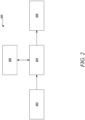
- the system 200 includes a first controller 202 associated with the earthmoving machine 102 (see FIG. 1 ).
- the first controller 202 may be present onboard the earthmoving machine 102.
- the first controller 202 receives information pertaining to the work area 300 on which the earthmoving machine 102 is required to perform one or more operations.
- the information pertaining to the work area 300 may be uploaded to the first controller 202 by an operator or a personnel in charge of the worksite 100 (see FIG. 1 ) or the earthmoving machine 102.
- the information pertaining to the work area 300 may be prestored within a memory (not shown) associated with the first controller 202.
- the one or more operations may include, for example, a grading operation, a material excavation operation, backfill or reclamation, and a material movement operation.
- the information pertaining to the work area 300 may include a virtual design boundary of the work area 300 on which the earthmoving machine 102 is required to perform the one or more operations.
- the virtual design boundary may include information such as a layout of the work area 300 and a surface area defined by the work area 300. It should be noted that the virtual design boundary of the work area 300 may be of any arbitrary shape and size.
- the first controller 202 may also receive details such as a location of the work area 300 or other parameters such as the presence of buildings, trees, or other objects/obstacles present on the work area 300. Further, the virtual design boundary of the work area 300 may be displayed on a display device (not shown) present within the earthmoving machine 102. Based on the receipt of the information pertaining to the work area 300, an operator of the earthmoving machine 102 may initiate operation of the earthmoving machine 102 for executing the one or more operations to be performed on the work area 300. In an example, when the earthmoving machine 102 initiates the one or more operations on the work area 300, the first controller 202 may transmit an elevation data of the work area 300 to a central controller 204.
- the system 200 also includes the central controller 204 coupled in communication with the first controller 202.
- the central controller 204 may execute instructions stored on a computer readable medium to perform methods for generating the work plan for the autonomous operation of the compactor 108 in tandem with the earthmoving machine 102.
- the central controller 204 may be located at a back office or a remote operator station.
- the central controller 204 may be in communication with a memory 206 via wired means or wireless means.
- the wireless means may include, for example, Wi-Fi, Bluetooth, or any other such means.
- the memory 206 may include, for example, a flash memory, a random-access memory (RAM), and an electrically erasable programmable read-only memory (EEPROM).
- the memory 206 may store data, such as, algorithms, instructions, and arithmetic operations.
- the central controller 204 may execute various types of digitally stored instructions such as a software or an algorithm, retrieved from the memory 206, or a firmware program which may enable the central controller 204 to perform a wide variety of operations.
- aspects of the present disclosure may be described generally as being stored in the memory 206, it may be contemplated that these aspects can be stored on or read from different types of computer program products or computer-readable media, such as, computer chips and secondary storage devices including hard disks, floppy disks, optical media, compact disc-read only memory (CD-ROM), or other forms of RAM or read only memory (ROM).
- the work plan generated by the central controller 204 may be stored in the memory 206.
- the central controller 204 receives the information pertaining to the work area 300 on which the earthmoving machine 102 is required to perform the one or more operations from the first controller 202.
- the central controller 204 may receive the elevation data and/or the virtual design boundary of the work area 300 from the first controller 202.
- the central controller 204 may receive data corresponding to the one or more operations being performed by the earthmoving machine 102.
- the information may be transmitted via wireless means, such as, Wi-Fi, Bluetooth, or any other such means.
- the data received from the first controller 202 may be stored in the memory 206 of the central controller 204 for further processing.
- the central controller 204 analyzes the work area 300 for virtually segmenting the work area 300 into a number of virtual work areas 306A, 306B, 306C, 306D, 306E, 306F, 306G, 306H based on a receipt of the information pertaining to the work area 300.
- the central controller 204 may analyze one or more convex vertices 314A, 314B, 314C, 314D, 314E, 314F, 314G, 314H, 3141 and one or more concave vertices 316A, 316B, 316C, 316D, 316E of the work area 300 for virtually segmenting the work area 300 into the number of virtual work areas 306A, 306B, 306C, 306D, 306E, 306F, 306G, 306H.
- convex vertex as used herein relates to a vertex on the virtual design boundary having an angle that is less than 180 degrees.
- concave vertex as used herein relates to a vertex on the virtual design boundary having an angle that is greater than 180 degrees.
- the work area 300 may be virtually segmented based on factors, such as, a length of each virtual work area 306A, 306B, 306C, 306D, 306E, 306F, 306G, 306H and/or the surface area of the work area 300, without any limitation thereto.
- a length of each virtual work area 306A, 306B, 306C, 306D, 306E, 306F, 306G, 306H may lie between 20 foot and 70 foot on ground, without any limitation thereto.
- a width of each virtual work area 306A, 306B, 306C, 306D, 306E, 306F, 306G, 306H may lie between 5 foot and 30 foot on ground, without any limitation thereto. It should be noted that although the work area 300 is virtually segmented along a length of the work area 300, it may be contemplated that the work area 300 may be virtually segmented along a width of the work area 300.
- the central controller 204 may determine one or more entry points 302 for the compactor 108 and exit points 304 for the compactor 108 based on an analysis of the number of convex vertices 314A, 314B, 314C, 314D, 314E, 314F, 314G, 314H, 3141.
- the work area 300 includes nine convex vertices 314A, 314B, 314C, 314D, 314E, 314F, 314G, 314H, 3141.
- the entry point 302 and the exit point 304 may be determined based on an analysis of a direction of movement of the earthmoving machine 102 (see FIG. 1 ) on the work area 300.
- the entry point 302 may be defined at any of a first end 308, a second end 310, or a third end 312 based on the direction of movement that the earthmoving machine 102 may have previously followed, without any limitation thereto.
- the exit point 304 may be defined at any of the first end 308, the second end 310, or the third end 312 based on the direction of movement that the earthmoving machine 102 may have previously followed, without any limitation thereto.
- the central controller 204 may determine all the convex vertices 314A, 314B, 314C, 314D, 314E, 314F, 314G, 314H, 314I present on the virtual design boundary corresponding to the work area 300.
- the central controller 204 may assign two of those convex vertices 314A, 314B, 314C, 314D, 314E, 314F, 314G, 314H, 3141 as the entry point 302 and two of those convex vertices 314A, 314B, 314C, 314D, 314E, 314F, 314G, 314H, 3141 as the exit point 304.
- the central controller 204 may determine an angle P1 defined by each convex vertex 314A, 314B, 314C, 314D, 314E, 314F, 314G, 314H, 3141. Further, the central controller 204 may determine from the virtual design boundary if any two convex vertices 314A, 314B, 314C, 314D, 314E, 314F, 314G, 314H, 3141 are located in succession to each other along a periphery of the virtual design boundary.
- the central controller 204 may assign the entry point 302 and/or the exit point 304.
- FIG. 3 illustrates two adjacent convex vertices 314A, 314B defined proximate to the first end 308, two adjacent convex vertices 314D, 314E defined proximate to the second end 310, and two adjacent convex vertices 314F, 314G defined proximate to the third end 312. Further, the summation of the angles P1 defined by the two convex vertices 314A, 314B is substantially equal to 180 degrees. Accordingly, the central controller 204 may assign the entry point 302 and/or the exit point 304 proximate to the first end 308.
- the central controller 204 may assign the entry point 302 and/or the exit point 304 proximate to the second end 310.
- the central controller 204 may assign the entry point 302 and/or the exit point 304 proximate to the third end 312.
- the central controller 204 may also generate entry and exit points for each virtual work area 306A, 306B, 306C, 306D, 306E, 306F, 306G, 306H.
- the central controller 204 may split the work area 300 into the number of virtual work areas 306A, 306B, 306C, 306D, 306E, 306F, 306G, 306H based on an angle P2 defined by the number of concave vertices 316A, 316B, 316C, 316D, 316E.
- the number of virtual work areas 306A, 306B, 306C, 306D, 306E, 306F, 306G, 306H may include one or more of a structured virtual work area and an unstructured virtual work area.
- structured virtual work area as used herein relates to the virtual work areas 306A, 306B, 306C, 306D, 306E, 306F, 306G, 306H that may have a definite shape, such as, a rectangular shape, a square shape, a triangular shape, and a trapezoidal shape, or any other such regular polygonal shape.
- unstructured virtual work area as described herein relates to virtual work areas generated on the work area 300 that may have an arbitrary and/or non-definite shapes.
- the present disclosure is not limited by scope in the determination of a structured/unstructured work area vis-à-vis a shape of the virtual work areas 306A, 306B, 306C, 306D, 306E, 306F, 306G, 306H.
- the central controller 204 may determine whether a particular virtual work area 306A, 306B, 306C, 306D, 306E, 306F, 306G, 306H is a structured work area or an unstructured work area based on the angle P2 defined at the number of concave vertices 316A, 316B, 316C, 316D, 316E. Further, the work area 300 includes five concave vertices 316A, 316B, 316C, 316D, 316E.
- the concave vertices 316A, 316B, 316C, 316D, 316E may be indicative of a bend or a turn on the work area 300 that the earthmoving machine 102 or the compactor 108 may operate on.
- the work area 300 may be virtually segmented into the virtual work areas 306A, 306B. Specifically, each virtual work area 306A, 306B is divided into a structured virtual work area having a substantially trapezoidal shape. Further, the work area 300 may be virtually segmented to form the virtual work area 306A based on a joining of the concave vertex 316A and the convex vertex 3141. Moreover, the work area 300 may be virtually segmented to form the virtual work area 306B based on a joining of the concave vertex 316B and the convex vertex 314H.
- the work area 300 may be virtually segmented into the virtual work area 306C.
- the virtual work area 306C is divided into a structured virtual work area that is substantially parallelogram shaped.
- the work area 300 may be virtually segmented to form the virtual work area 306C based on a joining of the concave vertex 316C and the convex vertex 314C.
- a portion of the work area 300 defined along an edge 318 of the work area 300 may be divided into the three virtual work areas 306D, 306E, 306F based on a size of the work area 300 defined along the edge 318.
- Each virtual work area 306D, 306E, 306F includes a rectangular shape.
- the angle P2 at the concave vertices 316D, 316E is approximately equal to 90 degrees.
- the work area 300 may be virtually segmented into the virtual work areas 306G, 306H.
- each of the virtual work areas 306G, 306H illustrated herein are structured virtual work areas having a substantially rectangular shape.
- the work area 300 may be virtually segmented to form the virtual work area 306G, 306H based on a joining of the concave vertex 316D and the concave vertex 316E. It should be further noted that a portion of the work area 300 defined along an edge 320 of the work area 300 may be divided into the two virtual work areas 306G, 306H based on a size of the work area 300 defined along the edge 320.
- FIG. 4A illustrates another exemplary technique for virtually segmenting the exemplary work area 400.
- the work area 400 defines a concave vertex 402A.
- An angle P3 defined by the concave vertex 402A is approximately equal to 90 degrees.
- the work area 400 may be virtually segmented into the virtual work areas 404A, 404B, 404C.
- each virtual work area 404A, 404B illustrated herein is a structured virtual work area having a substantially rectangular shape.
- the work area 400 may also be virtually segmented into the virtual work area 404C.
- the virtual work areas 404C illustrated herein is a structured virtual work area having a substantially square shape.
- the work area 406 defines a concave vertex 408A, such that an angle P4 defined by the concave vertex 408A is less than 60 degrees. As the concave vertex 408A is less than 60 degrees, the work area 406 may be virtually segmented into a virtual work area 410A. It should be noted that the virtual work area 410A includes an unstructured work area. The unstructured work area may have any arbitrary or non-definite shape.
- the central controller 204 may also determine if the earthmoving machine 102 has concluded the one or more operations on the one or more virtual work areas 306A, 306B, 306C, 306D, 306E, 306F, 306G, 306H (see FIG. 3 ).
- the central controller 204 may determine that the one or more operations have been concluded based on information received from the first controller 202.
- the operator of the earthmoving machine 102 may provide an input to the first controller 202 that may be indicative of the conclusion of the one or more operations on the one or more virtual work areas 306A, 306B, 306C, 306D, 306E, 306F, 306G, 306H.
- the first controller 202 may in turn transmit this information to the central controller 204 via wireless means, such as, Wi-Fi, Bluetooth, or any other such means.
- the central controller 204 may transmit the information indicative of the conclusion of the one or more operations at each of the virtual work areas 306A, 306B, 306C, 306D, 306E, 306F, 306G, 306H (see FIG. 3 ) to a second controller 208 associated with the compactor 108.
- the second controller 208 may be coupled in communication with the central controller 204.
- the central controller 204 may determine the optimal direction of movement on the one or more virtual work areas 306A, 306B, 306C, 306D, 306E, 306F, 306G, 306H from the number of virtual work areas 306A, 306B, 306C, 306D, 306E, 306F, 306G, 306H based on a conclusion of the one or more operations by the earthmoving machine 102. Further, the central controller 204 determines the optimal direction of movement for the compactor 108 based on the data indicative of the movement of the earthmoving machine 102. The compactor 108 moves along the optimal direction of movement during the autonomous operation of the compactor 108.
- the compactor 108 moves along the optimal direction of movement determined before-hand in accordance with the aforementioned embodiment of the present disclosure.
- the earthmoving machine 102 may follow a movement pattern D1 and D2, due to which the earthmoving machine 102 may push some material towards one edge and some material towards another edge.
- the earthmoving machine 102 may move diagonally and follow a movement pattern D3, due to which the earthmoving machine 102 may push the material sideways.
- the earthmoving machine 102 may follow a movement pattern D4, due to which the earthmoving machine 102 may push the material towards an edge from which the earthmoving machine 102 may have entered.
- the central controller 204 may analyze each of the movement patterns D1, D2, D3, D4 to determine an exemplary optimal direction of movement D5 for the compactor 108 (see FIG. 1 ).
- the optimal direction of movement D5 may typically embody a generalized and simplified pattern that may be generated taking into consideration the movement patterns D1, D2, D3, D4 of the earthmoving machine 102.
- the central controller 204 may also transmit information that may indicate which of the virtual work areas 306A, 306B, 306C, 306D, 306E, 306F, 306G, 306H have been worked upon by the earthmoving machine 102 (see FIG. 1 ).
- the work plan may include the information pertaining to the virtual work areas 306A, 306B, 306C, 306D, 306E, 306F, 306G, 306H on which the earthmoving machine 102 has already performed the one or more operations.
- the second controller 208 may receive information that the earthmoving machine 102 has concluded operations at the virtual work areas 306A, 306B, 306C and the earthmoving machine 102 is yet to conclude operations at the virtual work areas 306D, 306E, 306F, 306G, 306H. Based on this information, the compactor 108 may only perform the compaction operation on the virtual work areas 306A, 306B, 306C on which the earthmoving machine 102 has already performed the one or more operations.
- the second controller 208 located on the compactor 108 may control one or more components of the compactor 108 to move the compactor 108 for performing the compaction operation.
- the second controller 208 may control the drums 110 (see FIG. 1 ) of the compactor 108 for movement of the compactor 108 and subsequently to perform the compaction operation.
- the compactor 108 may move through the virtual work areas 306A, 306B, 306C, 306D, 306E, 306F, 306G, 306H in an order in which the earthmoving machine 102 may have performed the one or more operations on the virtual work areas 306A, 306B, 306C, 306D, 306E, 306F, 306G, 306H.
- the compactor 108 may also perform the compaction operation on the virtual work area 306A and may then directly move to the virtual work area 306C.
- the optimal direction of movement for the compactor 108 may be chosen from three possible directions D6, D7, D8 of movement of the earthmoving machine 102 (see FIG. 1 ) on the virtual work area 600.
- the central controller 204 may determine the optimal direction of movement for the compactor 108 based on, for example, a longest continuous edge 606 of the virtual work area 600 along which an overall deflection/change in the angle of the longest continuous edge 606 is less than a threshold angle, for example, less than 20 degrees.
- the optimal direction of movement for the compactor 108 may be determined based on position data of the earthmoving machine 102 at different instances of time. More particularly, the central controller 204 (see FIG. 2 ) may receive a number of position inputs associated with the earthmoving machine 102 from the first controller 202 (see FIG. 2 ). In an example, each position input from the number of position inputs may be indicative of the position of the earthmoving machine 102 on the one or more virtual work areas 600 with respect to time. In an example, the position inputs may be available in terms of 1 X 1 square feet polygons with timestamps. For example, as illustrated in FIG.
- polygons A1, A2, A3, A4 may be representative of position inputs along the direction D6 of the earthmoving machine 102 (see FIG. 1 ). Further, polygons B1, B2, B3, B4 may be representative of position inputs along the direction D7 of the earthmoving machine 102. Moreover, polygons C1, C2, C3, C4 may be representative of position inputs along the direction D8 of the earthmoving machine 102.
- the central controller 204 may generate a number of vectors based on an analysis of the number of position inputs.
- the polygons A1, A2, A3, A4, B1, B2, B3, B4, C1, C2, C3, C4 may be arranged in an ascending time sequence to form the vectors.
- the central controller 204 may join the polygons A1, A2, A3, A4, B1, B2, B3, B4, C1, C2, C3, C4 that are close to each other in time for generating the number of vectors.
- the vectors generated by the central controller 204 thus provide an indication of a magnitude and a direction of the earthmoving machine 102 to the central controller 204.
- the vectors generated by the central controller 204 may provide an indication of the directions D6, D7, D8 of the earthmoving machine 102 on the virtual work area 600.
- the central controller 204 may determine the optimal direction of movement for the compactor 108 based on an average dot product of the number of vectors.
- the central controller 204 may determine the average dot product of the number of vectors associated with the longest continuous edge 606 (see FIG. 6 ) of the virtual work area 600 as shown in FIG. 6 to find the optimal direction of movement for the compactor 108.
- the central controller 204 may determine the optimal direction of movement to be similar to the direction D6 or the direction D8.
- the central controller 204 may determine that the earthmoving machine 102 may be moving along the direction D6. However, if the average dot product of the vectors generated using the data of the polygons A1, A2, A3, A4 is negative, the central controller 204 may determine that the earthmoving machine 102 may be moving along the direction D8. It should be noted that, once the central controller 204 may determine the direction of movement of the earthmoving machine 102, the central controller 204 may determine an entry point through which the compactor 108 may enter the virtual work area 600 and an exit point through which the compactor 108 may exit the virtual work area 600.
- the direction of movement of the earthmoving machine 102 may not align with the longest continuous edge 606 of the virtual work area 600.
- the earthmoving machine 102 may move along the direction D7.
- the central controller 204 may override the direction D7 of movement of the earthmoving machine 102 and may determine the optimal direction of movement as the direction D6 or the direction D8.
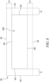
- the central controller 204 may generate a virtual fence 810 around the one or more virtual work areas 306E from the number of virtual work areas 306A, 306B, 306C, 306D, 306E, 306F, 306G, 306H based on the generation of the optimal direction of movement for the compactor 108.
- the virtual fence 810 being generated around the virtual work area 306E associated with the work area 300 will now be explained in detail.
- the central controller 204 may use the technique mentioned below for generating a corresponding virtual fence for each virtual work areas 306A, 306B, 306C, 306D, 306F, 306G, 306H (see FIG.
- the central controller 204 may generate a virtual fence (similar to the virtual fence 810) for the entire work area 300, 400, and 406 (see FIGS. 3 , 4A, and 4B, respectively). In this example, the central controller 204 may transmit the information pertaining to the optimal direction of movement when the earthmoving machine 102 is outside the virtual fence of the corresponding work area 300, 400, and 406.
- an area of the virtual fence 810 may be greater than an area of the one or more virtual work areas 306E.
- the central controller 204 may generate the virtual fence 810 after generating the optimal direction of movement for the compactor 108.
- the virtual work area 306E defines an entry point 802 and an exit point 804.
- the entry and exit points 802, 804 are sections through which the compactor 108 may enter and exit the virtual work area 306E.
- the virtual work area 306E also defines a first side edge 806 and a second side edge 808.
- the virtual fence 810 defines a fence entry point 812, such that a forward pathing distance V1 is defined between the fence entry point 812 of the virtual fence 810 and the entry point 802 of the virtual work area 306E.
- the fence entry point 812 of the virtual fence 810 may be indicative of a location from which the compactor 108 may enter the virtual fence 810.
- the forward pathing distance V1 may lie in a range of 10 meters to 20 meters, without any limitation thereto.
- the virtual fence 810 defines a fence exit point 814, such that a rearward pathing distance V2 is defined between the fence exit point 814 of the virtual fence 810 and the exit point 804 of the virtual work area 306E.
- the fence exit point 814 is a location of the virtual fence 810 from which the compactor 108 may exit the virtual fence 810.
- the rearward pathing distance V2 may lie in a range of 5 meters to 15 meters, without any limitation thereto.
- the virtual fence 810 also includes a first fence side edge 816, such that a first lean out distance V3 is defined between the first fence side edge 816 of the virtual fence 810 and the first side edge 806 of the virtual work area 306E. Additionally, the virtual fence 810 includes a second fence side edge 818, such that a second lean out distance V4 is defined between the second fence side edge 818 of the virtual fence 810 and the second side edge 808 of the virtual work area 306E. It should be noted that the term “first lean out distance” and the term “second lean out distance” as used herein may be regarded as an additional distance by which the compactor 108 can move beyond the corresponding edges 806, 808 of the virtual work area 306E.
- each of the first lean out distance V3 and the second lean out distance V4 may lie in a range of 1 meters to 5 meters, without any limitation thereto.
- the central controller 204 may determine the optimal direction of movement based on the conclusion of the one or more operations by the earthmoving machine 102. Further, the central controller 204 transmits the information pertaining to the optimal direction of movement to the compactor 108 when the earthmoving machine 102 is outside the virtual fence 810 generated around the one or more virtual work areas 306E. For example, when the earthmoving machine 102 may move outside the virtual fence 810 and enter an adjacent virtual work area, the central controller 204 may transmit the optimal direction of movement to the second controller 208.
- the central controller 204 may also determine if an on-grade at the virtual work area 306E is more than a threshold, for example, 80%. If the on-grade is more than the threshold, the central controller 204 may transmit the work plan containing the information pertaining to the optimal direction of movement to the second controller 208.
- a threshold for example, 80%.
- data pertaining to the virtual fence 810 that is generated by the central controller 204 is transmitted to the second controller 208. If the earthmoving machine 102 concludes the one or more operations on the virtual work area 306E and exits the corresponding virtual fence 810, the compactor 108 enters the virtual fence 810 for performing the compaction operation. It should be noted that the second controller 208 is programmed to prevent a movement of the compactor 108 outside the virtual fence 810 until the compaction operations are concluded on the virtual work area 306E.
- the central controller 204 may also transmit information pertaining to the virtual work areas 306A, 306B, 306C, 306D, 306F, 306G, 306H on which the earthmoving machine 102 may have concluded the one or more operations.
- the central controller 204 may also transmit information pertaining to the virtual fence 810, the fence entry point 812 from which the compactor 108 may enter the virtual fence 810, and/or the fence exit point 814 from which the compactor 108 may exit the virtual fence 810.
- the earthmoving machine 102 is operating in the virtual work area 306B and the compactor 108 is operating in the virtual work area 306A.
- the central controller 204 may transmit the work plan to the second controller 208.
- the compactor 108 may enter the virtual work area 306B for performing the compaction operations.
- each of the first controller 202, the second controller 208, and the central controller 204 may embody a single microprocessor or multiple microprocessors for receiving various input signals. Numerous commercially available microprocessors may be configured to perform the functions of respective ones of the first controller 202, the second controller 208, and the central controller 204. Each of the first controller 202, the second controller 208, and the central controller 204 may include a central processing unit, a graphics processing unit, and/or any other system associated hardware and networking circuitry, for instance, signal conditioning and/or processing circuitry.
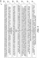
- FIG. 9 illustrates a flowchart depicting a method 900 for generating the work plan for the autonomous operation of the compactor 108 in tandem with the earthmoving machine 102.
- the first controller 202 associated with the earthmoving machine 102 receives the information pertaining to the work area 300 on which the earthmoving machine 102 is required to perform one or more operations.
- the central controller 204 receives the information pertaining to the work area 300 on which the earthmoving machine 102 is required to perform the one or more operations from the first controller 202.
- the central controller 204 is coupled in communication with the first controller 202.
- the central controller 204 analyzes the work area 300 for virtually segmenting the work area 300 into the number of virtual work areas 306A, 306B, 306C, 306D, 306E, 306F, 306G, 306H based on the receipt of the information pertaining to the work area 300.
- the central controller 204 analyzes one or more of the number of convex vertices 314A, 314B, 314C, 314D, 314E, 314F, 314G, 314H, 3141 and one or more of the number of number of concave vertices 316A, 316B, 316C, 316D, 316E of the work area 300 for virtually segmenting the work area 300 into the number of virtual work areas 306A, 306B, 306C, 306D, 306E, 306F, 306G, 306H.
- the central controller 204 virtually segments the work area 300 into the number of virtual work areas 306A, 306B, 306C, 306D, 306E, 306F, 306G, 306H based on the angle P2 defined by the number of concave vertices 316A, 316B, 316C, 316D, 316E.
- the number of virtual work areas 306A, 306B, 306C, 306D, 306E, 306F, 306G, 306H includes one or more of the structured virtual work area and the unstructured virtual work area.
- the central controller 204 determines one or more of the entry point 302 for the compactor 108 and the exit point 304 for the compactor 108 based on the analysis of the number of convex vertices 314A, 314B, 314C, 314D, 314E, 314F, 314G, 314H, 3141.
- the central controller 204 receives the data indicative of the movement of the earthmoving machine 102 through each of the number of virtual work areas 306A, 306B, 306C, 306D, 306E, 306F, 306G, 306H from the first controller 202.
- the central controller 204 determines the optimal direction of movement for the compactor 108 on the one or more virtual work areas 306A, 306B, 306C, 306D, 306E, 306F, 306G, 306H from the number of virtual work areas 306A, 306B, 306C, 306D, 306E, 306F, 306G, 306H based on the data indicative of the movement of the earthmoving machine 102, such that the compactor 108 moves along the optimal direction of movement during the autonomous operation of the compactor 108.
- the central controller 204 receives the number of position inputs associated with the earthmoving machine 102 from the first controller 202. Each position input from the number of position inputs is indicative of the position of the earthmoving machine 102 on the one or more virtual work areas 306A, 306B, 306C, 306D, 306E, 306F, 306G, 306H with respect to time. Further, the central controller 204 generates the number of vectors based on the analysis of the number of position inputs. Furthermore, the central controller 204 determines the optimal direction of movement for the compactor 108 based on the average dot product of the number of vectors.
- the central controller 204 generates the virtual fence 810 around the one or more virtual work areas 306E from the number of virtual work areas 306A, 306B, 306C, 306D, 306E, 306F, 306G, 306H based on the generation of the optimal direction of movement for the compactor 108.
- the central controller 204 generates the virtual fence 810 such that the area of the virtual fence 810 is greater than the area of the one or more virtual work areas 306E.
- the central controller 204 determines the optimal direction of movement based on the conclusion of the one or more operations by the earthmoving machine 102.
- the central controller 104 transmits the information pertaining to the optimal direction of movement to the compactor 108 when the earthmoving machine 102 is outside the virtual fence 810 generated around the one or more virtual work areas 306E. Further, the central controller 204 transmits the information pertaining to the optimal direction of movement to the second controller 208 associated with the compactor 108 when the earthmoving machine 102 is outside the virtual fence 810. The second controller 208 is coupled in communication with the central controller 204. It may be desirable to perform one or more of the steps associated with the method 900 in an order different from that depicted. Furthermore, various steps could be performed together.
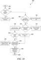
- FIG. 10 is a process flowchart 1000 for low-level implementation of the method 900 of FIG. 9 .
- the process 1000 may be executed by the central controller 204.
- the process 1000 may be stored within the memory 206 and may be retrieved for execution by the central controller 204.
- the process 1000 starts or begin operation.
- the central controller 204 determines if the earthmoving machine 102 has initiated the one or more operations on the work area 300.
- the process 1000 moves to a block 1006.
- the central controller 204 may wait until the central controller 204 receives information indicative of the initiation of the one or more operations on the work area 300 from the first controller 202.
- the process 1000 moves to a block 1008.
- the central controller 204 determines if the work area 300 has been virtually segmented.
- the process 1000 moves to a block 1010 to virtual segment the work area 300.
- the process 1000 moves to a block 1012.
- the central controller 204 determines if the earthmoving machine 102 has concluded the one or more operations on the one or more virtual work areas 306A, 306B, 306C, 306D, 306E, 306F, 306G, 306H.
- the central controller 204 determines that the earthmoving machine 102 has not concluded the one or more operations on the one or more virtual work areas 306A, 306B, 306C, 306D, 306E, 306F, 306G, 306H, the process 1000 moves to a block 1014.
- the central controller 204 may wait until the central controller 204 receives information indicative of the conclusion of the one or more operations on the one or more virtual work areas 306A, 306B, 306C, 306D, 306E, 306F, 306G, 306H from the first controller 202. However, at the block 1014, if the earthmoving machine 102 has concluded the one or more operations on the one or more virtual work areas 306A, 306B, 306C, 306D, 306E, 306F, 306G, 306H, the process 1000 moves to a block 1016. At the block 1016, the central controller 204 determines the optimal direction of movement for the compactor 108.
- the process 1000 then moves to a block 1018.
- the central controller 204 determines if the virtual fence 810 has been generated.
- the process 1000 moves to a block 1020.
- the central controller 204 generates the virtual fence 810.
- the process 1000 moves to a block 1022.
- the central controller 204 determines if the earthmoving machine 102 is outside the virtual fence 810.
- the central controller 204 may wait until the earthmoving machine 102 is outside the virtual fence 810.
- the process 1000 moves to a block 1026.
- the central controller 204 transmits the optimal direction of movement to the second controller 208 associated with the compactor 108. Further, the process 1000 terminates or ends operation at a block 1028.
- the present disclosure relates to the system 200 and the method 900 for generating the work plan for the autonomous operation of the compactor 108 in tandem with the earthmoving machine 102.
- this section will be explained in relation to operations being performed on the work area 300 by the earthmoving machine 102.
- the earthmoving machine 102 may perform the operations at the work areas 300 which may be large in size and may have a complex/irregular shape. However, it may be challenging for the compactor 108 to handle the work areas 300 that are large in size and/or have complex or irregular shapes.
- the central controller 204 associated with the system 200 transmits the information related to the smaller virtual work areas 306A, 306B, 306C, 306D, 306E, 306F, 306G, 306H that have been previously worked on by the earthmoving machine 102 to the second controller 208.
- the system 200 and the method 900 may allow autonomous operation of the compactor 108 once the earthmoving machine 102 has exited the virtual fence (such as, the virtual fence 810) around the corresponding virtual work area 306A, 306B, 306C, 306D, 306E, 306F, 306G, 306H.
- the central controller 204 may generate and transmit the information pertaining to each virtual work area 306A, 306B, 306C, 306D, 306E, 306F, 306G, 306H to the second controller 208 as and when the earthmoving machine 102 exits the corresponding virtual work area 306A, 306B, 306C, 306D, 306E, 306F, 306G, 306H.
- the compactor 108 may operate on the virtual work areas 306A, 306B, 306C, 306D, 306E, 306F, 306G, 306H that may have a smaller area and a definite shape. Accordingly, the virtual segmentation of the work area 300 may improve the autonomous operation of the compactor 108.
- the system 200 and the method 900 described herein may also increase a productivity and an efficiency at the worksite 100.
- the central controller 204 generates the optimal direction of movement for the compactor 108 based on the movement of the earthmoving machine 102 in each of the corresponding virtual work areas 306A, 306B, 306C, 306D, 306E, 306F, 306G, 306H.
- the optimal direction of movement for the compactor 108 being determined by the central controller 204 may be such that the compactor 108 may take least number of turns, or passes, for effectively performing the compaction operation, on the virtual work areas 306A, 306B, 306C, 306D, 306E, 306F, 306G, 306H.
- the optimal direction of movement being determined by the central controller 204 may be such that the compactor 108 performs the compaction operation at each desired location of the virtual work areas 306A, 306B, 306C, 306D, 306E, 306F, 306G, 306H. Further, in an example, the optimal direction of movement may be generated along long and continuous edges of the virtual work areas 306A, 306B, 306C, 306D, 306E, 306F, 306G, 306H which may allow the compactor 108 to move along straight paths without frequent changes to a steering and/or articulation angle of the compactor 108, thereby facilitating an increase in productivity of the compactor 108.
- the system 200 and the method 900 described herein may perform a vectorized rectangularization of the work area 300.
- the virtual segmentation of the work area 300 into the smaller virtual work areas 306A, 306B, 306C, 306D, 306E, 306F, 306G, 306H may also ensure that the second controller 208 associated with the compactor 108 receives data corresponding to each location of the work area 300 on which the earthmoving machine 102 may have performed the one or more operations.
- the second controller 208 may have exhaustive information of each portion of the work area 300 and therefore, enable autonomous operation of the compactor 108 In such examples, a likelihood of incomplete compaction operations on the work area 300 that were previously worked on by the earthmoving machine 102 may be minimized.
Landscapes
- Engineering & Computer Science (AREA)
- Structural Engineering (AREA)
- Mining & Mineral Resources (AREA)
- Civil Engineering (AREA)
- General Engineering & Computer Science (AREA)
- Radar, Positioning & Navigation (AREA)
- Aviation & Aerospace Engineering (AREA)
- Automation & Control Theory (AREA)
- General Physics & Mathematics (AREA)
- Physics & Mathematics (AREA)
- Remote Sensing (AREA)
- Life Sciences & Earth Sciences (AREA)
- Agronomy & Crop Science (AREA)
- Paleontology (AREA)
- General Life Sciences & Earth Sciences (AREA)
- Soil Sciences (AREA)
- Environmental & Geological Engineering (AREA)
- Control Of Position, Course, Altitude, Or Attitude Of Moving Bodies (AREA)
- Operation Control Of Excavators (AREA)
Abstract
Description
- The present disclosure relates to a system and a method for generating a work plan for autonomous operation of a compactor in tandem with an earthmoving machine.
- Various operations, such as material removal, material movement, and/or material distribution may have to be performed at a worksite before initiating construction of infrastructures such as, for example, roadways, speedways for motor vehicles, airport runways, dams, water spill ways, and residential or commercial facilities.
- Typically, worksite preparation may require the use of several types of machines. In some cases, a dozer may be required to perform a grading operation at a particular area of the worksite. Subsequently, the dozed worksite may be followed up with a compaction operation that may require use of a compactor thereon. With advancement of technology, machines are being designed to operate in an autonomous manner as they offer various advantages. For example, autonomous machines may be used to replace involvement or need for human workers/operators especially in unsuitable environments, such as, at high altitudes, or at sparsely populated regions. Further, autonomous machines may operate for longer periods of time as compared to manned machines, thereby increasing productivity. Furthermore, autonomous machines may be operated in accordance with precise control strategies aimed at fulfilling one or more end objectives, for instance, optimizing efficiency while reducing downtime and emissions.
-
U.S. Patent 6,112,143 discloses an apparatus and method for establishing the perimeter of a work site for a mobile machine capable of operating autonomously or semi-autonomously. The apparatus and method includes activating a learning mode, positioning the mobile machine at a plurality of locations on the perimeter, and recording position data at each location from a sensor system, such as GPS, that provide signals corresponding to the position of the mobile machine. The position data is stored and a data processor associated with a control system generates a display of the perimeter so that an operator may visually verify the size, location, and shape of the work area bounded by the perimeter. - In one aspect of the present disclosure, a system for generating a work plan for autonomous operation of a compactor in tandem with an earthmoving machine is provided. The system includes a first controller associated with the earthmoving machine. The first controller receives information pertaining to a work area on which the earthmoving machine is required to perform at least one operation. The system also includes a central controller coupled in communication with the first controller. The central controller is configured to receive, from the first controller, information pertaining to the work area on which the earthmoving machine is required to perform the at least one operation. The central controller is also configured to analyze the work area for virtually segmenting the work area into a plurality of virtual work areas based on a receipt of the information pertaining to the work area. The central controller is further configured to receive, from the first controller, data indicative of a movement of the earthmoving machine through each virtual work area from the plurality of virtual work areas. The central controller is configured to determine an optimal direction of movement for the compactor on at least one virtual work area from the plurality of virtual work areas based on the data indicative of the movement of the earthmoving machine, such that the compactor is configured to move along the optimal direction of movement during the autonomous operation of the compactor. The central controller is also configured to generate a virtual fence around the at least one virtual work area from the plurality of virtual work areas based on generation of the optimal direction of movement for the compactor. The central controller is further configured to transmit information pertaining to the optimal direction of movement to the compactor on the at least one virtual work area from the plurality of virtual work areas when the earthmoving machine is outside the virtual fence.
- In another aspect of the present disclosure, a method for generating a work plan for autonomous operation of a compactor in tandem with an earthmoving machine is provided. The method includes receiving, by a first controller associated with the earthmoving machine, information pertaining to a work area on which the earthmoving machine is required to perform at least one operation. The method also includes receiving, by a central controller, information pertaining to the work area on which the earthmoving machine is required to perform the at least one operation from the first controller. The central controller is coupled in communication with the first controller. The method further includes analyzing, by the central controller, the work area for virtually segmenting the work area into a plurality of virtual work areas based on a receipt of the information pertaining to the work area. The method includes receiving, by the central controller, data indicative of a movement of the earthmoving machine through each of the plurality of virtual work areas from the first controller. The method also includes determining, by the central controller, an optimal direction of movement for the compactor on at least one virtual work area from the plurality of virtual work areas based on the data indicative of the movement of the earthmoving machine, such that the compactor is configured to move along the optimal direction of movement during the autonomous operation of the compactor. The method also includes generating, by the central controller, a virtual fence around the at least one virtual work area from the plurality of virtual work areas based on generation of the optimal direction of movement for the compactor. The method further includes transmitting, by the central controller, information pertaining to the optimal direction of movement to the compactor on the at least one virtual work area from the plurality of virtual work areas when the earthmoving machine is outside the virtual fence.
- In yet another aspect of the present disclosure, a computer readable medium having computer executable instructions for performing a method for generating a work plan for autonomous operation of a compactor in tandem with an earthmoving machine. The method includes receiving information pertaining to a work area on which the earthmoving machine is required to perform at least one operation. The method also includes analyzing the work area for virtually segmenting the work area into a plurality of virtual work areas based on a receipt of the information pertaining to the work area. The method further includes receiving data indicative of a movement of the earthmoving machine through each of the plurality of virtual work areas. The method includes determining an optimal direction of movement for the compactor on at least one virtual work area from the plurality of virtual work areas based on the data indicative of the movement of the earthmoving machine, such that the compactor is configured to move along the optimal direction of movement during the autonomous operation of the compactor. The method also includes generating a virtual fence around the at least one virtual work area from the plurality of virtual work areas based on generation of the optimal direction of movement for the compactor. The method further includes transmitting information pertaining to the optimal direction of movement to the compactor on the at least one virtual work area from the plurality of virtual work areas when the earthmoving machine is outside the virtual fence.
- Other features and aspects of this disclosure will be apparent from the following description and the accompanying drawings.
-
-
FIG. 1 is a pictorial view depicting an earthmoving machine and a compactor operating at a worksite, according to an exemplary embodiment of the present disclosure; -
FIG. 2 is a block diagram depicting a system for generating a work plan for autonomous operation of the compactor in tandem with the earthmoving machine, according to an exemplary embodiment of the present disclosure; -
FIG. 3 is a schematic view of an exemplary work area on which the earthmoving machine may operate; - FIG. 4A is a schematic view illustrating various structured virtual work areas associated with another exemplary work area;
- FIG. 4B is a schematic view illustrating an exemplary unstructured virtual work area associated with yet another exemplary work area;
-
FIG. 5 is a schematic view illustrating various exemplary movement patterns associated with the earthmoving machine and an exemplary optimal direction of movement for the compactor; -
FIG. 6 is a schematic view of an exemplary virtual work area including a continuous edge; -
FIG. 7 is a schematic view illustrating exemplary data received from a first controller associated with the earthmoving machine; -
FIG. 8 is a schematic view of an exemplary virtual work area on which the earthmoving machine may operate; -
FIG. 9 is a flowchart depicting a method for generating the work plan for the autonomous operation of the compactor in tandem with the earthmoving machine, according to an exemplary embodiment of the present disclosure; and -
FIG. 10 is a process flowchart for low-level implementation of the method ofFIG. 9 , according to an exemplary embodiment of the present disclosure. - Wherever possible, the same reference numbers will be used throughout the drawings to refer to the same or like parts. Wherever possible, corresponding or similar reference numbers will be used throughout the drawings to refer to the same or corresponding parts.
- Referring to
FIG. 1 , a portion of anexemplary worksite 100 is illustrated. Theworksite 100 may include, for example, a mine site, a land fill, a quarry, and a construction site. Theworksite 100 may be any worksite, such as, for construction of roadways or access roads, residential complexes, or commercial complexes, or any other type of worksite on which work or labor may be performed. - In one example, the
worksite 100 may undergo geographic alterations due to work being performed thereon by one or more earthmoving machines. For example, anearthmoving machine 102 embodied as a dozer may operate at theworksite 100. Theearthmoving machine 102 includes animplement 104 and a pair of ground engaging members 106 (only one of which is illustrated herein) embodied as tracks. Theearthmoving machine 102 may perform one or more tasks such as a grading operation or any other geography-altering tasks at theworksite 100. Alternatively, theearthmoving machine 102 may be embodied as an excavator, a tractor, a loader, a grader, a scraper, or any other machine that may perform earthmoving operations. - Further, a
compactor 108 may also operate at theworksite 100 and in tandem with theearthmoving machine 102. For example, thecompactor 108 may perform a compaction operation at theworksite 100 previously worked upon by theearthmoving machine 102. Thecompactor 108 may be embodied as a soil compactor. In another example, thecompactor 108 may be embodied as a pneumatic compactor. Thecompactor 108 includes a pair ofdrums 110. Alternatively, thecompactor 108 may include a single drum and a pair of wheels. Thecompactor 108 disclosed herein is embodied as an autonomous compactor or a semi-autonomous compactor. - For exemplary purposes, one
earthmoving machine 102 and onecompactor 108 are illustrated inFIG. 1 . However, more than oneearthmoving machine 102 and more than onecompactor 108 may operate at theworksite 100 depending on specific requirements of an application. Further, theearthmoving machine 102 and thecompactor 108 may operate on one or moreexemplary work areas FIGS. 3 , 4A, and 4B, respectively) defined at theworksite 100. - Referring to
FIG. 2 , asystem 200 for generating a work plan for autonomous operation of the compactor 108 (seeFIG. 1 ) in tandem with the earthmoving machine 102(seeFIG. 1 ) is illustrated. The work plan may include details, such as, an optimal direction of movement for thecompactor 108, an entry point 302, 304 (shown inFIG. 3 ) from which thecompactor 108 may enter thework area FIGS. 3 , 4A, and 4B, respectively) to be worked on, an exit point 302, 304 from which thecompactor 108 may exit thework area work areas compactor 108 is required to perform the compaction operation. For explanatory purposes, thesystem 200 will now be explained in relation to operations being performed on thework area 300 by theearthmoving machine 102. However, the description provided below is equally applicable to theother work areas - As shown in
FIG. 2 , thesystem 200 includes afirst controller 202 associated with the earthmoving machine 102 (seeFIG. 1 ). Thefirst controller 202 may be present onboard theearthmoving machine 102. Thefirst controller 202 receives information pertaining to thework area 300 on which theearthmoving machine 102 is required to perform one or more operations. The information pertaining to thework area 300 may be uploaded to thefirst controller 202 by an operator or a personnel in charge of the worksite 100 (seeFIG. 1 ) or theearthmoving machine 102. In an example, the information pertaining to thework area 300 may be prestored within a memory (not shown) associated with thefirst controller 202. The one or more operations may include, for example, a grading operation, a material excavation operation, backfill or reclamation, and a material movement operation. - In an example, the information pertaining to the
work area 300 may include a virtual design boundary of thework area 300 on which theearthmoving machine 102 is required to perform the one or more operations. The virtual design boundary may include information such as a layout of thework area 300 and a surface area defined by thework area 300. It should be noted that the virtual design boundary of thework area 300 may be of any arbitrary shape and size. - In an example, in addition to the virtual design boundary of the
work area 300, thefirst controller 202 may also receive details such as a location of thework area 300 or other parameters such as the presence of buildings, trees, or other objects/obstacles present on thework area 300. Further, the virtual design boundary of thework area 300 may be displayed on a display device (not shown) present within theearthmoving machine 102. Based on the receipt of the information pertaining to thework area 300, an operator of theearthmoving machine 102 may initiate operation of theearthmoving machine 102 for executing the one or more operations to be performed on thework area 300. In an example, when theearthmoving machine 102 initiates the one or more operations on thework area 300, thefirst controller 202 may transmit an elevation data of thework area 300 to acentral controller 204. - Further, the
system 200 also includes thecentral controller 204 coupled in communication with thefirst controller 202. Thecentral controller 204 may execute instructions stored on a computer readable medium to perform methods for generating the work plan for the autonomous operation of thecompactor 108 in tandem with theearthmoving machine 102. Thecentral controller 204 may be located at a back office or a remote operator station. Thecentral controller 204 may be in communication with amemory 206 via wired means or wireless means. The wireless means may include, for example, Wi-Fi, Bluetooth, or any other such means. Thememory 206 may include, for example, a flash memory, a random-access memory (RAM), and an electrically erasable programmable read-only memory (EEPROM). Thememory 206 may store data, such as, algorithms, instructions, and arithmetic operations. Thecentral controller 204 may execute various types of digitally stored instructions such as a software or an algorithm, retrieved from thememory 206, or a firmware program which may enable thecentral controller 204 to perform a wide variety of operations. Although aspects of the present disclosure may be described generally as being stored in thememory 206, it may be contemplated that these aspects can be stored on or read from different types of computer program products or computer-readable media, such as, computer chips and secondary storage devices including hard disks, floppy disks, optical media, compact disc-read only memory (CD-ROM), or other forms of RAM or read only memory (ROM). In some examples, the work plan generated by thecentral controller 204 may be stored in thememory 206. - The
central controller 204 receives the information pertaining to thework area 300 on which theearthmoving machine 102 is required to perform the one or more operations from thefirst controller 202. For example, thecentral controller 204 may receive the elevation data and/or the virtual design boundary of thework area 300 from thefirst controller 202. Moreover, thecentral controller 204 may receive data corresponding to the one or more operations being performed by theearthmoving machine 102. The information may be transmitted via wireless means, such as, Wi-Fi, Bluetooth, or any other such means. In an example, the data received from thefirst controller 202 may be stored in thememory 206 of thecentral controller 204 for further processing. - As shown in
FIG. 3 , the central controller 204 (seeFIG. 2 ) analyzes thework area 300 for virtually segmenting thework area 300 into a number ofvirtual work areas work area 300. More particularly, thecentral controller 204 may analyze one or moreconvex vertices concave vertices work area 300 for virtually segmenting thework area 300 into the number ofvirtual work areas - The
work area 300 may be virtually segmented based on factors, such as, a length of eachvirtual work area work area 300, without any limitation thereto. In an example, a length of eachvirtual work area virtual work area work area 300 is virtually segmented along a length of thework area 300, it may be contemplated that thework area 300 may be virtually segmented along a width of thework area 300. - The
central controller 204 may determine one or more entry points 302 for thecompactor 108 and exit points 304 for thecompactor 108 based on an analysis of the number ofconvex vertices work area 300 includes nineconvex vertices FIG. 1 ) on thework area 300. Accordingly, in an example, the entry point 302 may be defined at any of afirst end 308, asecond end 310, or athird end 312 based on the direction of movement that theearthmoving machine 102 may have previously followed, without any limitation thereto. Moreover, in an example, the exit point 304 may be defined at any of thefirst end 308, thesecond end 310, or thethird end 312 based on the direction of movement that theearthmoving machine 102 may have previously followed, without any limitation thereto. - For determining the entry point 302 and the exit point 304, the
central controller 204 may determine all theconvex vertices work area 300. If an effective angle change on edges with theconvex vertices central controller 204 may assign two of thoseconvex vertices convex vertices central controller 204 may determine an angle P1 defined by eachconvex vertex central controller 204 may determine from the virtual design boundary if any twoconvex vertices convex vertices central controller 204 may assign the entry point 302 and/or the exit point 304. -
FIG. 3 illustrates two adjacentconvex vertices 314A, 314B defined proximate to thefirst end 308, two adjacent convex vertices 314D, 314E defined proximate to thesecond end 310, and two adjacentconvex vertices third end 312. Further, the summation of the angles P1 defined by the twoconvex vertices 314A, 314B is substantially equal to 180 degrees. Accordingly, thecentral controller 204 may assign the entry point 302 and/or the exit point 304 proximate to thefirst end 308. - Further, the summation of the angles P1 defined by the two convex vertices 314D, 314E is substantially equal to 180 degrees, the
central controller 204 may assign the entry point 302 and/or the exit point 304 proximate to thesecond end 310. Similarly, the summation of the angles P1 defined by the twoconvex vertices central controller 204 may assign the entry point 302 and/or the exit point 304 proximate to thethird end 312. In an example, thecentral controller 204 may also generate entry and exit points for eachvirtual work area - Further, the
central controller 204 may split thework area 300 into the number ofvirtual work areas concave vertices virtual work areas virtual work areas work area 300 that may have an arbitrary and/or non-definite shapes. It should be noted that the present disclosure is not limited by scope in the determination of a structured/unstructured work area vis-à-vis a shape of thevirtual work areas - The
central controller 204 may determine whether a particularvirtual work area concave vertices work area 300 includes fiveconcave vertices concave vertices work area 300 that theearthmoving machine 102 or thecompactor 108 may operate on. - In an example, when the angle P2 at each of the
concave vertices 316A, 316B lies approximately between 60 degrees and 140 degrees, thework area 300 may be virtually segmented into the virtual work areas 306A, 306B. Specifically, each virtual work area 306A, 306B is divided into a structured virtual work area having a substantially trapezoidal shape. Further, thework area 300 may be virtually segmented to form the virtual work area 306A based on a joining of the concave vertex 316A and theconvex vertex 3141. Moreover, thework area 300 may be virtually segmented to form the virtual work area 306B based on a joining of theconcave vertex 316B and theconvex vertex 314H. Further, as the angle P2 at theconcave vertex 316C lies approximately between 60 degrees and 140 degrees, thework area 300 may be virtually segmented into thevirtual work area 306C. Specifically, thevirtual work area 306C is divided into a structured virtual work area that is substantially parallelogram shaped. Further, thework area 300 may be virtually segmented to form thevirtual work area 306C based on a joining of theconcave vertex 316C and theconvex vertex 314C. Further, a portion of thework area 300 defined along anedge 318 of thework area 300 may be divided into the threevirtual work areas work area 300 defined along theedge 318. Eachvirtual work area - Furthermore, the angle P2 at the
concave vertices 316D, 316E is approximately equal to 90 degrees. In such an example, thework area 300 may be virtually segmented into thevirtual work areas virtual work areas work area 300 may be virtually segmented to form thevirtual work area concave vertex 316D and the concave vertex 316E. It should be further noted that a portion of thework area 300 defined along anedge 320 of thework area 300 may be divided into the twovirtual work areas work area 300 defined along theedge 320. - FIG. 4A illustrates another exemplary technique for virtually segmenting the
exemplary work area 400. As shown in FIG. 4A, thework area 400 defines aconcave vertex 402A. An angle P3 defined by theconcave vertex 402A is approximately equal to 90 degrees. Further, thework area 400 may be virtually segmented into thevirtual work areas virtual work area work area 400 may also be virtually segmented into thevirtual work area 404C. Thevirtual work areas 404C illustrated herein is a structured virtual work area having a substantially square shape. - Referring now to FIG. 4B, another exemplary technique for virtually segmenting the
exemplary work area 406 is illustrated. As shown in FIG. 4B, thework area 406 defines aconcave vertex 408A, such that an angle P4 defined by theconcave vertex 408A is less than 60 degrees. As theconcave vertex 408A is less than 60 degrees, thework area 406 may be virtually segmented into avirtual work area 410A. It should be noted that thevirtual work area 410A includes an unstructured work area. The unstructured work area may have any arbitrary or non-definite shape. - Referring again to
FIGS. 1 and2 , thecentral controller 204 may also determine if theearthmoving machine 102 has concluded the one or more operations on the one or morevirtual work areas FIG. 3 ). Thecentral controller 204 may determine that the one or more operations have been concluded based on information received from thefirst controller 202. For example, the operator of theearthmoving machine 102 may provide an input to thefirst controller 202 that may be indicative of the conclusion of the one or more operations on the one or morevirtual work areas first controller 202 may in turn transmit this information to thecentral controller 204 via wireless means, such as, Wi-Fi, Bluetooth, or any other such means. - Further, in an example, the
central controller 204 may transmit the information indicative of the conclusion of the one or more operations at each of thevirtual work areas FIG. 3 ) to asecond controller 208 associated with thecompactor 108. Thesecond controller 208 may be coupled in communication with thecentral controller 204. - In an example, the
central controller 204 may determine the optimal direction of movement on the one or morevirtual work areas virtual work areas earthmoving machine 102. Further, thecentral controller 204 determines the optimal direction of movement for thecompactor 108 based on the data indicative of the movement of theearthmoving machine 102. Thecompactor 108 moves along the optimal direction of movement during the autonomous operation of thecompactor 108. Specifically, during autonomous operation, thecompactor 108 moves along the optimal direction of movement determined before-hand in accordance with the aforementioned embodiment of the present disclosure. For example, as illustrated inFIG. 5 , the earthmoving machine 102 (seeFIG. 2 ) may follow a movement pattern D1 and D2, due to which theearthmoving machine 102 may push some material towards one edge and some material towards another edge. Alternatively, theearthmoving machine 102 may move diagonally and follow a movement pattern D3, due to which theearthmoving machine 102 may push the material sideways. Further, theearthmoving machine 102 may follow a movement pattern D4, due to which theearthmoving machine 102 may push the material towards an edge from which theearthmoving machine 102 may have entered. - It should be noted that the movement patterns D1, D2, D3, D4 illustrated herein are exemplary in nature, and the
earthmoving machine 102 may follow any other movement pattern, without any limitations. The central controller 204 (seeFIG. 2 ) may analyze each of the movement patterns D1, D2, D3, D4 to determine an exemplary optimal direction of movement D5 for the compactor 108 (seeFIG. 1 ). The optimal direction of movement D5 may typically embody a generalized and simplified pattern that may be generated taking into consideration the movement patterns D1, D2, D3, D4 of theearthmoving machine 102. - Referring to
FIGS. 2 and3 , in addition to the optimal direction of movement, thecentral controller 204 may also transmit information that may indicate which of thevirtual work areas FIG. 1 ). Thus, the work plan may include the information pertaining to thevirtual work areas earthmoving machine 102 has already performed the one or more operations. For example, thesecond controller 208 may receive information that theearthmoving machine 102 has concluded operations at thevirtual work areas 306A, 306B, 306C and theearthmoving machine 102 is yet to conclude operations at thevirtual work areas compactor 108 may only perform the compaction operation on thevirtual work areas 306A, 306B, 306C on which theearthmoving machine 102 has already performed the one or more operations. - Based on receipt of the work plan from the
central controller 204, thesecond controller 208 located on thecompactor 108 may control one or more components of thecompactor 108 to move thecompactor 108 for performing the compaction operation. For example, thesecond controller 208 may control the drums 110 (seeFIG. 1 ) of thecompactor 108 for movement of thecompactor 108 and subsequently to perform the compaction operation. - In an example, the
compactor 108 may move through thevirtual work areas earthmoving machine 102 may have performed the one or more operations on thevirtual work areas earthmoving machine 102 performs the operations on the virtual work area 306A and directly moves to thevirtual work area 306C, thecompactor 108 may also perform the compaction operation on the virtual work area 306A and may then directly move to thevirtual work area 306C. - Referring now to
FIG. 6 , the exemplaryvirtual work area 600 is illustrated. In an example, the optimal direction of movement for the compactor 108 (seeFIG. 1 ) may be chosen from three possible directions D6, D7, D8 of movement of the earthmoving machine 102 (seeFIG. 1 ) on thevirtual work area 600. Thecentral controller 204 may determine the optimal direction of movement for thecompactor 108 based on, for example, a longestcontinuous edge 606 of thevirtual work area 600 along which an overall deflection/change in the angle of the longestcontinuous edge 606 is less than a threshold angle, for example, less than 20 degrees. - The optimal direction of movement for the
compactor 108 may be determined based on position data of theearthmoving machine 102 at different instances of time. More particularly, the central controller 204 (seeFIG. 2 ) may receive a number of position inputs associated with theearthmoving machine 102 from the first controller 202 (seeFIG. 2 ). In an example, each position input from the number of position inputs may be indicative of the position of theearthmoving machine 102 on the one or morevirtual work areas 600 with respect to time. In an example, the position inputs may be available in terms of 1X 1 square feet polygons with timestamps. For example, as illustrated inFIG. 7 , polygons A1, A2, A3, A4 may be representative of position inputs along the direction D6 of the earthmoving machine 102 (seeFIG. 1 ). Further, polygons B1, B2, B3, B4 may be representative of position inputs along the direction D7 of theearthmoving machine 102. Moreover, polygons C1, C2, C3, C4 may be representative of position inputs along the direction D8 of theearthmoving machine 102. - Further, the central controller 204 (see
FIG. 2 ) may generate a number of vectors based on an analysis of the number of position inputs. In an example, the polygons A1, A2, A3, A4, B1, B2, B3, B4, C1, C2, C3, C4 may be arranged in an ascending time sequence to form the vectors. Furthermore, thecentral controller 204 may join the polygons A1, A2, A3, A4, B1, B2, B3, B4, C1, C2, C3, C4 that are close to each other in time for generating the number of vectors. The vectors generated by thecentral controller 204 thus provide an indication of a magnitude and a direction of theearthmoving machine 102 to thecentral controller 204. For example, in the context of the present disclosure, the vectors generated by thecentral controller 204 may provide an indication of the directions D6, D7, D8 of theearthmoving machine 102 on thevirtual work area 600. - Moreover, the
central controller 204 may determine the optimal direction of movement for thecompactor 108 based on an average dot product of the number of vectors. In an example, thecentral controller 204 may determine the average dot product of the number of vectors associated with the longest continuous edge 606 (seeFIG. 6 ) of thevirtual work area 600 as shown inFIG. 6 to find the optimal direction of movement for thecompactor 108. Accordingly, in an example, thecentral controller 204 may determine the optimal direction of movement to be similar to the direction D6 or the direction D8. - Further, if the average dot product of the vectors generated using the data of the polygons A1, A2, A3, A4 is positive, the
central controller 204 may determine that theearthmoving machine 102 may be moving along the direction D6. However, if the average dot product of the vectors generated using the data of the polygons A1, A2, A3, A4 is negative, thecentral controller 204 may determine that theearthmoving machine 102 may be moving along the direction D8. It should be noted that, once thecentral controller 204 may determine the direction of movement of theearthmoving machine 102, thecentral controller 204 may determine an entry point through which thecompactor 108 may enter thevirtual work area 600 and an exit point through which thecompactor 108 may exit thevirtual work area 600. - In an example, it may be possible that the direction of movement of the
earthmoving machine 102 may not align with the longestcontinuous edge 606 of thevirtual work area 600. For example, theearthmoving machine 102 may move along the direction D7. In such examples, thecentral controller 204 may override the direction D7 of movement of theearthmoving machine 102 and may determine the optimal direction of movement as the direction D6 or the direction D8. - Referring to
FIG. 8 , thecentral controller 204 may generate avirtual fence 810 around the one or morevirtual work areas 306E from the number ofvirtual work areas compactor 108. For sake of simplicity, thevirtual fence 810 being generated around thevirtual work area 306E associated with thework area 300 will now be explained in detail. However, it should be noted that thecentral controller 204 may use the technique mentioned below for generating a corresponding virtual fence for eachvirtual work areas FIG. 3 ) associated with thework area 300, thevirtual work areas virtual work area 410A (see FIG. 4B) associated with the work area 406 (see FIG. 4B), and the virtual work area 600 (seeFIG. 6 ). In another example, thecentral controller 204 may generate a virtual fence (similar to the virtual fence 810) for theentire work area FIGS. 3 , 4A, and 4B, respectively). In this example, thecentral controller 204 may transmit the information pertaining to the optimal direction of movement when theearthmoving machine 102 is outside the virtual fence of thecorresponding work area - Further, an area of the
virtual fence 810 may be greater than an area of the one or morevirtual work areas 306E. In an example, thecentral controller 204 may generate thevirtual fence 810 after generating the optimal direction of movement for thecompactor 108. As illustrated, thevirtual work area 306E defines anentry point 802 and anexit point 804. The entry and exit points 802, 804 are sections through which thecompactor 108 may enter and exit thevirtual work area 306E. Thevirtual work area 306E also defines afirst side edge 806 and asecond side edge 808. Further, thevirtual fence 810 defines afence entry point 812, such that a forward pathing distance V1 is defined between thefence entry point 812 of thevirtual fence 810 and theentry point 802 of thevirtual work area 306E. It should be noted that thefence entry point 812 of thevirtual fence 810 may be indicative of a location from which thecompactor 108 may enter thevirtual fence 810. In an example, the forward pathing distance V1 may lie in a range of 10 meters to 20 meters, without any limitation thereto. - Furthermore, the
virtual fence 810 defines afence exit point 814, such that a rearward pathing distance V2 is defined between thefence exit point 814 of thevirtual fence 810 and theexit point 804 of thevirtual work area 306E. It should be noted that thefence exit point 814 is a location of thevirtual fence 810 from which thecompactor 108 may exit thevirtual fence 810. In an example, the rearward pathing distance V2 may lie in a range of 5 meters to 15 meters, without any limitation thereto. - Moreover, the
virtual fence 810 also includes a firstfence side edge 816, such that a first lean out distance V3 is defined between the firstfence side edge 816 of thevirtual fence 810 and thefirst side edge 806 of thevirtual work area 306E. Additionally, thevirtual fence 810 includes a secondfence side edge 818, such that a second lean out distance V4 is defined between the secondfence side edge 818 of thevirtual fence 810 and thesecond side edge 808 of thevirtual work area 306E. It should be noted that the term "first lean out distance" and the term "second lean out distance" as used herein may be regarded as an additional distance by which thecompactor 108 can move beyond the correspondingedges virtual work area 306E. In an example, each of the first lean out distance V3 and the second lean out distance V4 may lie in a range of 1 meters to 5 meters, without any limitation thereto. Thecentral controller 204 may determine the optimal direction of movement based on the conclusion of the one or more operations by theearthmoving machine 102. Further, thecentral controller 204 transmits the information pertaining to the optimal direction of movement to thecompactor 108 when theearthmoving machine 102 is outside thevirtual fence 810 generated around the one or morevirtual work areas 306E. For example, when theearthmoving machine 102 may move outside thevirtual fence 810 and enter an adjacent virtual work area, thecentral controller 204 may transmit the optimal direction of movement to thesecond controller 208. For a grading operation, thecentral controller 204 may also determine if an on-grade at thevirtual work area 306E is more than a threshold, for example, 80%. If the on-grade is more than the threshold, thecentral controller 204 may transmit the work plan containing the information pertaining to the optimal direction of movement to thesecond controller 208. - It should be noted that data pertaining to the
virtual fence 810 that is generated by thecentral controller 204 is transmitted to thesecond controller 208. If theearthmoving machine 102 concludes the one or more operations on thevirtual work area 306E and exits the correspondingvirtual fence 810, thecompactor 108 enters thevirtual fence 810 for performing the compaction operation. It should be noted that thesecond controller 208 is programmed to prevent a movement of thecompactor 108 outside thevirtual fence 810 until the compaction operations are concluded on thevirtual work area 306E. - It should be noted that, in addition to the optimal direction of movement for the
compactor 108, thecentral controller 204 may also transmit information pertaining to thevirtual work areas earthmoving machine 102 may have concluded the one or more operations. In an example, thecentral controller 204 may also transmit information pertaining to thevirtual fence 810, thefence entry point 812 from which thecompactor 108 may enter thevirtual fence 810, and/or thefence exit point 814 from which thecompactor 108 may exit thevirtual fence 810. - As illustrated in
FIG. 1 , theearthmoving machine 102 is operating in the virtual work area 306B and thecompactor 108 is operating in the virtual work area 306A. When theearthmoving machine 102 concludes the operations in the virtual work area 306B and moves outside a virtual fence (not shown) of the virtual work area 306B, thecentral controller 204 may transmit the work plan to thesecond controller 208. Further, once thecompactor 108 concludes the compaction operations on the virtual work area 306A, thecompactor 108 may enter the virtual work area 306B for performing the compaction operations. - It should be noted that each of the
first controller 202, thesecond controller 208, and thecentral controller 204 may embody a single microprocessor or multiple microprocessors for receiving various input signals. Numerous commercially available microprocessors may be configured to perform the functions of respective ones of thefirst controller 202, thesecond controller 208, and thecentral controller 204. Each of thefirst controller 202, thesecond controller 208, and thecentral controller 204 may include a central processing unit, a graphics processing unit, and/or any other system associated hardware and networking circuitry, for instance, signal conditioning and/or processing circuitry. -
FIG. 9 illustrates a flowchart depicting amethod 900 for generating the work plan for the autonomous operation of thecompactor 108 in tandem with theearthmoving machine 102. Referring toFIGS. 1 ,2 ,3 , and9 , atstep 902, thefirst controller 202 associated with theearthmoving machine 102 receives the information pertaining to thework area 300 on which theearthmoving machine 102 is required to perform one or more operations. Atstep 904, thecentral controller 204 receives the information pertaining to thework area 300 on which theearthmoving machine 102 is required to perform the one or more operations from thefirst controller 202. Thecentral controller 204 is coupled in communication with thefirst controller 202. - At
step 906, thecentral controller 204 analyzes thework area 300 for virtually segmenting thework area 300 into the number ofvirtual work areas work area 300. Thecentral controller 204 analyzes one or more of the number ofconvex vertices concave vertices work area 300 for virtually segmenting thework area 300 into the number ofvirtual work areas central controller 204 virtually segments thework area 300 into the number ofvirtual work areas concave vertices virtual work areas central controller 204 determines one or more of the entry point 302 for thecompactor 108 and the exit point 304 for thecompactor 108 based on the analysis of the number ofconvex vertices - At
step 908, thecentral controller 204 receives the data indicative of the movement of theearthmoving machine 102 through each of the number ofvirtual work areas first controller 202. Atstep 910, thecentral controller 204 determines the optimal direction of movement for thecompactor 108 on the one or morevirtual work areas virtual work areas earthmoving machine 102, such that thecompactor 108 moves along the optimal direction of movement during the autonomous operation of thecompactor 108. - Referring now to
FIGS. 1 ,2 ,6 , and9 , in an example, thecentral controller 204 receives the number of position inputs associated with theearthmoving machine 102 from thefirst controller 202. Each position input from the number of position inputs is indicative of the position of theearthmoving machine 102 on the one or morevirtual work areas central controller 204 generates the number of vectors based on the analysis of the number of position inputs. Furthermore, thecentral controller 204 determines the optimal direction of movement for thecompactor 108 based on the average dot product of the number of vectors. - Moreover, referring to
FIGS. 1 ,2 ,8 , and9 , atstep 912, thecentral controller 204 generates thevirtual fence 810 around the one or morevirtual work areas 306E from the number ofvirtual work areas compactor 108. Thecentral controller 204 generates thevirtual fence 810 such that the area of thevirtual fence 810 is greater than the area of the one or morevirtual work areas 306E. In an example, thecentral controller 204 determines the optimal direction of movement based on the conclusion of the one or more operations by theearthmoving machine 102. Further, atstep 914, thecentral controller 104 transmits the information pertaining to the optimal direction of movement to thecompactor 108 when theearthmoving machine 102 is outside thevirtual fence 810 generated around the one or morevirtual work areas 306E. Further, thecentral controller 204 transmits the information pertaining to the optimal direction of movement to thesecond controller 208 associated with thecompactor 108 when theearthmoving machine 102 is outside thevirtual fence 810. Thesecond controller 208 is coupled in communication with thecentral controller 204. It may be desirable to perform one or more of the steps associated with themethod 900 in an order different from that depicted. Furthermore, various steps could be performed together. -
FIG. 10 is aprocess flowchart 1000 for low-level implementation of themethod 900 ofFIG. 9 . Referring toFIGS. 1 ,2 ,3 , and10 , theprocess 1000 may be executed by thecentral controller 204. Theprocess 1000 may be stored within thememory 206 and may be retrieved for execution by thecentral controller 204. At ablock 1002, theprocess 1000 starts or begin operation. At ablock 1004, thecentral controller 204 determines if theearthmoving machine 102 has initiated the one or more operations on thework area 300. At theblock 1004, if thecentral controller 204 determines that theearthmoving machine 102 has not initiated the one or more operations on thework area 300, theprocess 1000 moves to ablock 1006. At theblock 1006, thecentral controller 204 may wait until thecentral controller 204 receives information indicative of the initiation of the one or more operations on thework area 300 from thefirst controller 202. - However, at the
block 1004, if thecentral controller 204 determines that theearthmoving machine 102 has initiated the one or more operations on thework area 300, theprocess 1000 moves to ablock 1008. At theblock 1008, thecentral controller 204 determines if thework area 300 has been virtually segmented. At theblock 1008, if thecentral controller 204 determines that thework area 300 has not been virtually segmented, theprocess 1000 moves to ablock 1010 to virtual segment thework area 300. - However, at the
block 1008, if thecentral controller 204 determines that thework area 300 has been virtually segmented, theprocess 1000 moves to ablock 1012. At theblock 1012, thecentral controller 204 determines if theearthmoving machine 102 has concluded the one or more operations on the one or morevirtual work areas block 1012, if thecentral controller 204 determines that theearthmoving machine 102 has not concluded the one or more operations on the one or morevirtual work areas process 1000 moves to ablock 1014. - At the
block 1014, thecentral controller 204 may wait until thecentral controller 204 receives information indicative of the conclusion of the one or more operations on the one or morevirtual work areas first controller 202. However, at theblock 1014, if theearthmoving machine 102 has concluded the one or more operations on the one or morevirtual work areas process 1000 moves to ablock 1016. At theblock 1016, thecentral controller 204 determines the optimal direction of movement for thecompactor 108. - The
process 1000 then moves to ablock 1018. Referring now toFIGS. 1 ,2 ,8 , and10 , at theblock 1018, thecentral controller 204 determines if thevirtual fence 810 has been generated. At theblock 1018, if thecentral controller 204 determines that thevirtual fence 810 has not been generated, theprocess 1000 moves to ablock 1020. At theblock 1020, thecentral controller 204 generates thevirtual fence 810. However, at theblock 1018, if thecentral controller 204 determines that thevirtual fence 810 has been generated, theprocess 1000 moves to ablock 1022. At theblock 1022, thecentral controller 204 determines if theearthmoving machine 102 is outside thevirtual fence 810. At theblock 1022, if thecentral controller 204 determines that theearthmoving machine 102 is not outside theprocess 1000 moves to ablock 1024. At theblock 1024, thecentral controller 204 may wait until theearthmoving machine 102 is outside thevirtual fence 810. - However, at the
block 1022, if thecentral controller 204 determines that theearthmoving machine 102 is outside thevirtual fence 810, theprocess 1000 moves to ablock 1026. At theblock 1026, thecentral controller 204 transmits the optimal direction of movement to thesecond controller 208 associated with thecompactor 108. Further, theprocess 1000 terminates or ends operation at ablock 1028. - The present disclosure relates to the
system 200 and themethod 900 for generating the work plan for the autonomous operation of thecompactor 108 in tandem with theearthmoving machine 102. For explanatory purposes, this section will be explained in relation to operations being performed on thework area 300 by theearthmoving machine 102. - The
earthmoving machine 102 may perform the operations at thework areas 300 which may be large in size and may have a complex/irregular shape. However, it may be challenging for thecompactor 108 to handle thework areas 300 that are large in size and/or have complex or irregular shapes. According to the present disclosure, thecentral controller 204 associated with thesystem 200 transmits the information related to the smallervirtual work areas earthmoving machine 102 to thesecond controller 208. - Further, the
system 200 and themethod 900 may allow autonomous operation of thecompactor 108 once theearthmoving machine 102 has exited the virtual fence (such as, the virtual fence 810) around the correspondingvirtual work area central controller 204 may generate and transmit the information pertaining to eachvirtual work area second controller 208 as and when theearthmoving machine 102 exits the correspondingvirtual work area compactor 108 may operate on thevirtual work areas work area 300 may improve the autonomous operation of thecompactor 108. Thesystem 200 and themethod 900 described herein may also increase a productivity and an efficiency at theworksite 100. - Further, the
central controller 204 generates the optimal direction of movement for thecompactor 108 based on the movement of theearthmoving machine 102 in each of the correspondingvirtual work areas compactor 108 being determined by thecentral controller 204 may be such that thecompactor 108 may take least number of turns, or passes, for effectively performing the compaction operation, on thevirtual work areas central controller 204 may be such that thecompactor 108 performs the compaction operation at each desired location of thevirtual work areas virtual work areas compactor 108 to move along straight paths without frequent changes to a steering and/or articulation angle of thecompactor 108, thereby facilitating an increase in productivity of thecompactor 108. - Moreover, the
system 200 and themethod 900 described herein may perform a vectorized rectangularization of thework area 300. Further, the virtual segmentation of thework area 300 into the smallervirtual work areas second controller 208 associated with thecompactor 108 receives data corresponding to each location of thework area 300 on which theearthmoving machine 102 may have performed the one or more operations. Thus, thesecond controller 208 may have exhaustive information of each portion of thework area 300 and therefore, enable autonomous operation of thecompactor 108 In such examples, a likelihood of incomplete compaction operations on thework area 300 that were previously worked on by theearthmoving machine 102 may be minimized. - While aspects of the present disclosure have been particularly shown and described with reference to the embodiments above, it will be understood by those skilled in the art that various additional embodiments may be contemplated by the modification of the disclosed machines, systems, and methods without departing from the spirit and scope of what is disclosed. Such embodiments should be understood to fall within the scope of the present disclosure as determined based upon the claims and any equivalents thereof.
Claims (7)
- A system (200) for generating a work plan for autonomous operation of a compactor (108) in tandem with an earthmoving machine (102), the system (200) comprising:a first controller (202) associated with the earthmoving machine (102), wherein the first controller (202) receives information pertaining to a work area (300) on which the earthmoving machine (102) is required to perform at least one operation; anda central controller (204) coupled in communication with the first controller (202), wherein the central controller (204) is configured to:receive, from the first controller (202), the information pertaining to the work area (300) on which the earthmoving machine (102) is required to perform the at least one operation;analyze the work area (300) for virtually segmenting the work area (300) into a plurality of virtual work areas (306A, 306B, 306C, 306D, 306E, 306F, 306G, 306H) based on a receipt of the information pertaining to the work area (300);receive, from the first controller (202), data indicative of a movement of the earthmoving machine (102) through each virtual work area (306A, 306B, 306C, 306D, 306E, 306F, 306G, 306H) from the plurality of virtual work areas (306A, 306B, 306C, 306D, 306E, 306F, 306G, 306H);determine an optimal direction of movement (D5) for the compactor (108) on at least one virtual work area (306A, 306B, 306C, 306D, 306E, 306F, 306G, 306H) from the plurality of virtual work areas (306A, 306B, 306C, 306D, 306E, 306F, 306G, 306H) based on the data indicative of the movement of the earthmoving machine (102), such that the compactor (108) is configured to move along the optimal direction of movement (D5) during the autonomous operation of the compactor (108);generate a virtual fence (810) around the at least one virtual work area (306A, 306B, 306C, 306D, 306E, 306F, 306G, 306H) from the plurality of virtual work areas (306A, 306B, 306C, 306D, 306E, 306F, 306G, 306H) based on generation of the optimal direction of movement (D5) for the compactor (108); andtransmit information pertaining to the optimal direction of movement (D5) to the compactor (108) when the earthmoving machine (102) is outside the virtual fence (810) generated around the at least one virtual work area (306A, 306B, 306C, 306D, 306E, 306F, 306G, 306H).
- The system (200) of claim 1, wherein the central controller (204) is configured to:receive, from the first controller (202), a plurality of position inputs associated with the earthmoving machine (102), wherein each position input from the plurality of position inputs is indicative of the position of the earthmoving machine (102) on the at least one work area (300) with respect to time;generate a plurality of vectors based on an analysis of the plurality of position inputs; anddetermine the optimal direction of movement (D5) for the compactor (108) based on an average dot product of the plurality of vectors.
- The system (200) of claim 1, wherein the central controller (204) is configured to analyze at least one of a plurality of convex vertices (314A, 314B, 314C, 314D, 314E, 314F, 314G, 314H, 3141) and at least one of a plurality of concave vertices (316A, 316B, 316C, 316D, 316E) on the work area (300) for virtually segmenting the work area (300) into the plurality of virtual work areas (306A, 306B, 306C, 306D, 306E, 306F, 306G, 306H).
- The system (200) of claim 3, wherein the central controller (204) is configured to virtually segment the work area (300) into the plurality of virtual work areas (306A, 306B, 306C, 306D, 306E, 306F, 306G, 306H) based on an angle (P2) defined by the plurality of concave vertices (316A, 316B, 316C, 316D, 316E), and wherein the plurality of virtual work areas (306A, 306B, 306C, 306D, 306E, 306F, 306G, 306H) includes at least one of a structured virtual work area and an unstructured virtual work area.
- The system (200) of claim 3, wherein the central controller (204) is configured to determine at least one of an entry point (302) for the compactor (108) and an exit point (304) for the compactor (108) based on an analysis of the plurality of convex vertices (314A, 314B, 314C, 314D, 314E, 314F, 314G, 314H, 314I).
- The system (200) of claim 1, wherein an area of the virtual fence (810) is configured to be greater than an area of the at least one virtual work area (306A, 306B, 306C, 306D, 306E, 306F, 306G, 306H).
- The system (200) of claim 6, wherein the central controller (204) is configured to:determine the optimal direction of movement (D5) based on a conclusion of the at least one operation by the earthmoving machine (102); andtransmit, to a second controller (208) associated with the compactor (108), the information pertaining to the optimal direction of movement (D5) when the earthmoving machine (102) is outside the virtual fence (810), wherein the second controller (208) is coupled in communication with the central controller (204).
Applications Claiming Priority (1)
| Application Number | Priority Date | Filing Date | Title |
|---|---|---|---|
| IN202111058477 | 2021-12-12 |
Publications (2)
| Publication Number | Publication Date |
|---|---|
| EP4194988A1 true EP4194988A1 (en) | 2023-06-14 |
| EP4194988B1 EP4194988B1 (en) | 2024-03-06 |
Family
ID=84421477
Family Applications (1)
| Application Number | Title | Priority Date | Filing Date |
|---|---|---|---|
| EP22207933.7A Active EP4194988B1 (en) | 2021-12-12 | 2022-11-17 | System and method for generating a work plan for autonomous operation of a compactor |
Country Status (3)
| Country | Link |
|---|---|
| US (1) | US12404654B2 (en) |
| EP (1) | EP4194988B1 (en) |
| AU (1) | AU2022275448A1 (en) |
Families Citing this family (1)
| Publication number | Priority date | Publication date | Assignee | Title |
|---|---|---|---|---|
| US12601121B2 (en) | 2023-08-01 | 2026-04-14 | Caterpillar Paving Products Inc. | Control of a work machine using ground surface work records |
Citations (5)
| Publication number | Priority date | Publication date | Assignee | Title |
|---|---|---|---|---|
| US6112143A (en) | 1998-08-06 | 2000-08-29 | Caterpillar Inc. | Method and apparatus for establishing a perimeter defining an area to be traversed by a mobile machine |
| CN107807644A (en) * | 2017-10-30 | 2018-03-16 | 洛阳中科龙网创新科技有限公司 | A kind of farm machinery consumption minimization trajectory path planning method |
| US20190186094A1 (en) * | 2017-12-14 | 2019-06-20 | Caterpillar Paving Products Inc. | System and method for compacting a worksite surface |
| US20210008997A1 (en) * | 2019-07-08 | 2021-01-14 | Caterpillar Paving Products Inc. | System and method for charging machines |
| US20210149403A1 (en) * | 2019-11-15 | 2021-05-20 | Built Robotics Inc. | Loading earth into a vehicle using a cooperative fleet of vehicles |
Family Cites Families (15)
| Publication number | Priority date | Publication date | Assignee | Title |
|---|---|---|---|---|
| AU547146B2 (en) | 1982-07-13 | 1985-10-10 | Kubota Ltd. | Automatic running work vehicle |
| US6088644A (en) | 1998-08-12 | 2000-07-11 | Caterpillar Inc. | Method and apparatus for determining a path to be traversed by a mobile machine |
| US7731450B2 (en) | 2006-09-07 | 2010-06-08 | Caterpillar Inc. | Method of operating a compactor machine via path planning based on compaction state data and mapping information |
| US20130311153A1 (en) * | 2012-05-15 | 2013-11-21 | Caterpillar Inc. | Virtual environment and method for sorting among potential route plans for operating autonomous machine at work site |
| US9606544B2 (en) * | 2014-10-31 | 2017-03-28 | Clearpath Robotics, Inc. | System, computing device and method for unmanned vehicle fleet control |
| JP6716195B2 (en) | 2015-01-19 | 2020-07-01 | 鹿島建設株式会社 | Construction machine construction method and construction machine construction system |
| DE102015122149A1 (en) | 2015-12-17 | 2017-06-22 | Ammann Schweiz Ag | Method for the autonomous operation of a compacting device |
| US20170200306A1 (en) | 2016-01-08 | 2017-07-13 | Caterpillar Paving Products Inc. | Control system for coordinating earth-working machines |
| US10407872B2 (en) | 2017-08-15 | 2019-09-10 | Caterpillar Inc. | System and method for controlling earthmoving machines |
| CN108646755A (en) | 2018-07-03 | 2018-10-12 | 清华大学 | A kind of cubic meter of intelligent rcc system |
| US11054831B2 (en) * | 2018-09-27 | 2021-07-06 | Caterpillar Paving Products Inc. | Automatic site planning for autonomous construction vehicles |
| CA3232590A1 (en) * | 2019-04-05 | 2020-10-08 | Equipmentshare.Com Inc. | System and method for autonomous operation of a machine |
| JP7555838B2 (en) * | 2020-02-19 | 2024-09-25 | ヤンマーパワーテクノロジー株式会社 | Area registration method and area registration system |
| EP4125316A1 (en) * | 2020-05-01 | 2023-02-08 | Kinze Manufacturing, Inc. | Shared planter data |
| JP7481908B2 (en) | 2020-05-29 | 2024-05-13 | 株式会社小松製作所 | Drilling plan creating device, work machine, and drilling plan creating method |
-
2022
- 2022-11-17 EP EP22207933.7A patent/EP4194988B1/en active Active
- 2022-11-23 AU AU2022275448A patent/AU2022275448A1/en active Pending
- 2022-12-14 US US18/081,268 patent/US12404654B2/en active Active
Patent Citations (5)
| Publication number | Priority date | Publication date | Assignee | Title |
|---|---|---|---|---|
| US6112143A (en) | 1998-08-06 | 2000-08-29 | Caterpillar Inc. | Method and apparatus for establishing a perimeter defining an area to be traversed by a mobile machine |
| CN107807644A (en) * | 2017-10-30 | 2018-03-16 | 洛阳中科龙网创新科技有限公司 | A kind of farm machinery consumption minimization trajectory path planning method |
| US20190186094A1 (en) * | 2017-12-14 | 2019-06-20 | Caterpillar Paving Products Inc. | System and method for compacting a worksite surface |
| US20210008997A1 (en) * | 2019-07-08 | 2021-01-14 | Caterpillar Paving Products Inc. | System and method for charging machines |
| US20210149403A1 (en) * | 2019-11-15 | 2021-05-20 | Built Robotics Inc. | Loading earth into a vehicle using a cooperative fleet of vehicles |
Also Published As
| Publication number | Publication date |
|---|---|
| AU2022275448A1 (en) | 2023-06-29 |
| US20230183944A1 (en) | 2023-06-15 |
| EP4194988B1 (en) | 2024-03-06 |
| US12404654B2 (en) | 2025-09-02 |
Similar Documents
| Publication | Publication Date | Title |
|---|---|---|
| CN111857124B (en) | System and method for machine control | |
| CN114945883B (en) | Systems and methods for autonomous movement of materials | |
| US9506224B2 (en) | Grade control cleanup pass using splines | |
| US9260837B1 (en) | Intelligent pass jump control | |
| US9891605B2 (en) | Grade control cleanup pass using volume constraints | |
| US20070129869A1 (en) | System for autonomous cooperative control of multiple machines | |
| JP7257240B2 (en) | Systems and methods for controlling work machines | |
| US20220259822A1 (en) | Automated Mobilization of Mobile Machines | |
| CN114322993B (en) | Method and system for generating loading area map of unmanned transport system of surface mine | |
| JP7257239B2 (en) | Systems and methods for controlling work machines | |
| US20210149403A1 (en) | Loading earth into a vehicle using a cooperative fleet of vehicles | |
| US20160040388A1 (en) | Grade Control Cleanup Pass Using Cost Optimization | |
| US20160082954A1 (en) | Method for controlling operations of multiple machines | |
| US12103119B2 (en) | Robotic welding system with orbital welder positioned on robotic arm | |
| EP4194988B1 (en) | System and method for generating a work plan for autonomous operation of a compactor | |
| US9297146B1 (en) | Automatic ripping pass detection | |
| AU2019202837B2 (en) | System and method of layering material | |
| KR20230165500A (en) | Construction machinary and driving method of the same | |
| AU2017276226B2 (en) | Dual blade implement system | |
| US20250362688A1 (en) | System and method for generating work plan for autonomous operation of compactor | |
| Moon et al. | Effectiveness of remote control for a concrete surface grinding machine | |
| US20250304068A1 (en) | System and method for machine control using road surface quality data | |
| KR20230164521A (en) | Construction machinary and drivable area determining method of the same | |
| CA3164854A1 (en) | Methods and systems for guiding mission planning in a machine system |
Legal Events
| Date | Code | Title | Description |
|---|---|---|---|
| PUAI | Public reference made under article 153(3) epc to a published international application that has entered the european phase |
Free format text: ORIGINAL CODE: 0009012 |
|
| STAA | Information on the status of an ep patent application or granted ep patent |
Free format text: STATUS: THE APPLICATION HAS BEEN PUBLISHED |
|
| AK | Designated contracting states |
Kind code of ref document: A1 Designated state(s): AL AT BE BG CH CY CZ DE DK EE ES FI FR GB GR HR HU IE IS IT LI LT LU LV MC ME MK MT NL NO PL PT RO RS SE SI SK SM TR |
|
| STAA | Information on the status of an ep patent application or granted ep patent |
Free format text: STATUS: REQUEST FOR EXAMINATION WAS MADE |
|
| 17P | Request for examination filed |
Effective date: 20230815 |
|
| RBV | Designated contracting states (corrected) |
Designated state(s): AL AT BE BG CH CY CZ DE DK EE ES FI FR GB GR HR HU IE IS IT LI LT LU LV MC ME MK MT NL NO PL PT RO RS SE SI SK SM TR |
|
| GRAP | Despatch of communication of intention to grant a patent |
Free format text: ORIGINAL CODE: EPIDOSNIGR1 |
|
| STAA | Information on the status of an ep patent application or granted ep patent |
Free format text: STATUS: GRANT OF PATENT IS INTENDED |
|
| RIC1 | Information provided on ipc code assigned before grant |
Ipc: E01C 19/00 20060101ALI20230914BHEP Ipc: E01F 9/20 20160101ALI20230914BHEP Ipc: G05D 1/02 20200101AFI20230914BHEP |
|
| INTG | Intention to grant announced |
Effective date: 20230929 |
|
| GRAS | Grant fee paid |
Free format text: ORIGINAL CODE: EPIDOSNIGR3 |
|
| GRAA | (expected) grant |
Free format text: ORIGINAL CODE: 0009210 |
|
| STAA | Information on the status of an ep patent application or granted ep patent |
Free format text: STATUS: THE PATENT HAS BEEN GRANTED |
|
| P01 | Opt-out of the competence of the unified patent court (upc) registered |
Effective date: 20240110 |
|
| AK | Designated contracting states |
Kind code of ref document: B1 Designated state(s): AL AT BE BG CH CY CZ DE DK EE ES FI FR GB GR HR HU IE IS IT LI LT LU LV MC ME MK MT NL NO PL PT RO RS SE SI SK SM TR |
|
| REG | Reference to a national code |
Ref country code: CH Ref legal event code: EP |
|
| REG | Reference to a national code |
Ref country code: IE Ref legal event code: FG4D |
|
| REG | Reference to a national code |
Ref country code: DE Ref legal event code: R096 Ref document number: 602022002265 Country of ref document: DE |
|
| REG | Reference to a national code |
Ref country code: LT Ref legal event code: MG9D |
|
| PG25 | Lapsed in a contracting state [announced via postgrant information from national office to epo] |
Ref country code: LT Free format text: LAPSE BECAUSE OF FAILURE TO SUBMIT A TRANSLATION OF THE DESCRIPTION OR TO PAY THE FEE WITHIN THE PRESCRIBED TIME-LIMIT Effective date: 20240306 |
|
| REG | Reference to a national code |
Ref country code: NL Ref legal event code: MP Effective date: 20240306 |
|
| PG25 | Lapsed in a contracting state [announced via postgrant information from national office to epo] |
Ref country code: GR Free format text: LAPSE BECAUSE OF FAILURE TO SUBMIT A TRANSLATION OF THE DESCRIPTION OR TO PAY THE FEE WITHIN THE PRESCRIBED TIME-LIMIT Effective date: 20240607 |
|
| PG25 | Lapsed in a contracting state [announced via postgrant information from national office to epo] |
Ref country code: HR Free format text: LAPSE BECAUSE OF FAILURE TO SUBMIT A TRANSLATION OF THE DESCRIPTION OR TO PAY THE FEE WITHIN THE PRESCRIBED TIME-LIMIT Effective date: 20240306 Ref country code: RS Free format text: LAPSE BECAUSE OF FAILURE TO SUBMIT A TRANSLATION OF THE DESCRIPTION OR TO PAY THE FEE WITHIN THE PRESCRIBED TIME-LIMIT Effective date: 20240606 |
|
| PG25 | Lapsed in a contracting state [announced via postgrant information from national office to epo] |
Ref country code: ES Free format text: LAPSE BECAUSE OF FAILURE TO SUBMIT A TRANSLATION OF THE DESCRIPTION OR TO PAY THE FEE WITHIN THE PRESCRIBED TIME-LIMIT Effective date: 20240306 |
|
| PG25 | Lapsed in a contracting state [announced via postgrant information from national office to epo] |
Ref country code: RS Free format text: LAPSE BECAUSE OF FAILURE TO SUBMIT A TRANSLATION OF THE DESCRIPTION OR TO PAY THE FEE WITHIN THE PRESCRIBED TIME-LIMIT Effective date: 20240606 Ref country code: NO Free format text: LAPSE BECAUSE OF FAILURE TO SUBMIT A TRANSLATION OF THE DESCRIPTION OR TO PAY THE FEE WITHIN THE PRESCRIBED TIME-LIMIT Effective date: 20240606 Ref country code: LT Free format text: LAPSE BECAUSE OF FAILURE TO SUBMIT A TRANSLATION OF THE DESCRIPTION OR TO PAY THE FEE WITHIN THE PRESCRIBED TIME-LIMIT Effective date: 20240306 Ref country code: HR Free format text: LAPSE BECAUSE OF FAILURE TO SUBMIT A TRANSLATION OF THE DESCRIPTION OR TO PAY THE FEE WITHIN THE PRESCRIBED TIME-LIMIT Effective date: 20240306 Ref country code: GR Free format text: LAPSE BECAUSE OF FAILURE TO SUBMIT A TRANSLATION OF THE DESCRIPTION OR TO PAY THE FEE WITHIN THE PRESCRIBED TIME-LIMIT Effective date: 20240607 Ref country code: FI Free format text: LAPSE BECAUSE OF FAILURE TO SUBMIT A TRANSLATION OF THE DESCRIPTION OR TO PAY THE FEE WITHIN THE PRESCRIBED TIME-LIMIT Effective date: 20240306 Ref country code: ES Free format text: LAPSE BECAUSE OF FAILURE TO SUBMIT A TRANSLATION OF THE DESCRIPTION OR TO PAY THE FEE WITHIN THE PRESCRIBED TIME-LIMIT Effective date: 20240306 Ref country code: BG Free format text: LAPSE BECAUSE OF FAILURE TO SUBMIT A TRANSLATION OF THE DESCRIPTION OR TO PAY THE FEE WITHIN THE PRESCRIBED TIME-LIMIT Effective date: 20240306 |
|
| REG | Reference to a national code |
Ref country code: AT Ref legal event code: MK05 Ref document number: 1664167 Country of ref document: AT Kind code of ref document: T Effective date: 20240306 |
|
| PG25 | Lapsed in a contracting state [announced via postgrant information from national office to epo] |
Ref country code: SE Free format text: LAPSE BECAUSE OF FAILURE TO SUBMIT A TRANSLATION OF THE DESCRIPTION OR TO PAY THE FEE WITHIN THE PRESCRIBED TIME-LIMIT Effective date: 20240306 Ref country code: LV Free format text: LAPSE BECAUSE OF FAILURE TO SUBMIT A TRANSLATION OF THE DESCRIPTION OR TO PAY THE FEE WITHIN THE PRESCRIBED TIME-LIMIT Effective date: 20240306 |
|
| PG25 | Lapsed in a contracting state [announced via postgrant information from national office to epo] |
Ref country code: NL Free format text: LAPSE BECAUSE OF FAILURE TO SUBMIT A TRANSLATION OF THE DESCRIPTION OR TO PAY THE FEE WITHIN THE PRESCRIBED TIME-LIMIT Effective date: 20240306 |
|
| PG25 | Lapsed in a contracting state [announced via postgrant information from national office to epo] |
Ref country code: NL Free format text: LAPSE BECAUSE OF FAILURE TO SUBMIT A TRANSLATION OF THE DESCRIPTION OR TO PAY THE FEE WITHIN THE PRESCRIBED TIME-LIMIT Effective date: 20240306 |
|
| PG25 | Lapsed in a contracting state [announced via postgrant information from national office to epo] |
Ref country code: IS Free format text: LAPSE BECAUSE OF FAILURE TO SUBMIT A TRANSLATION OF THE DESCRIPTION OR TO PAY THE FEE WITHIN THE PRESCRIBED TIME-LIMIT Effective date: 20240706 |
|
| PG25 | Lapsed in a contracting state [announced via postgrant information from national office to epo] |
Ref country code: PT Free format text: LAPSE BECAUSE OF FAILURE TO SUBMIT A TRANSLATION OF THE DESCRIPTION OR TO PAY THE FEE WITHIN THE PRESCRIBED TIME-LIMIT Effective date: 20240708 Ref country code: SM Free format text: LAPSE BECAUSE OF FAILURE TO SUBMIT A TRANSLATION OF THE DESCRIPTION OR TO PAY THE FEE WITHIN THE PRESCRIBED TIME-LIMIT Effective date: 20240306 |
|
| PG25 | Lapsed in a contracting state [announced via postgrant information from national office to epo] |
Ref country code: CZ Free format text: LAPSE BECAUSE OF FAILURE TO SUBMIT A TRANSLATION OF THE DESCRIPTION OR TO PAY THE FEE WITHIN THE PRESCRIBED TIME-LIMIT Effective date: 20240306 Ref country code: EE Free format text: LAPSE BECAUSE OF FAILURE TO SUBMIT A TRANSLATION OF THE DESCRIPTION OR TO PAY THE FEE WITHIN THE PRESCRIBED TIME-LIMIT Effective date: 20240306 |
|
| PG25 | Lapsed in a contracting state [announced via postgrant information from national office to epo] |
Ref country code: AT Free format text: LAPSE BECAUSE OF FAILURE TO SUBMIT A TRANSLATION OF THE DESCRIPTION OR TO PAY THE FEE WITHIN THE PRESCRIBED TIME-LIMIT Effective date: 20240306 |
|
| PG25 | Lapsed in a contracting state [announced via postgrant information from national office to epo] |
Ref country code: PL Free format text: LAPSE BECAUSE OF FAILURE TO SUBMIT A TRANSLATION OF THE DESCRIPTION OR TO PAY THE FEE WITHIN THE PRESCRIBED TIME-LIMIT Effective date: 20240306 |
|
| PG25 | Lapsed in a contracting state [announced via postgrant information from national office to epo] |
Ref country code: SK Free format text: LAPSE BECAUSE OF FAILURE TO SUBMIT A TRANSLATION OF THE DESCRIPTION OR TO PAY THE FEE WITHIN THE PRESCRIBED TIME-LIMIT Effective date: 20240306 |
|
| PG25 | Lapsed in a contracting state [announced via postgrant information from national office to epo] |
Ref country code: SM Free format text: LAPSE BECAUSE OF FAILURE TO SUBMIT A TRANSLATION OF THE DESCRIPTION OR TO PAY THE FEE WITHIN THE PRESCRIBED TIME-LIMIT Effective date: 20240306 Ref country code: SK Free format text: LAPSE BECAUSE OF FAILURE TO SUBMIT A TRANSLATION OF THE DESCRIPTION OR TO PAY THE FEE WITHIN THE PRESCRIBED TIME-LIMIT Effective date: 20240306 Ref country code: RO Free format text: LAPSE BECAUSE OF FAILURE TO SUBMIT A TRANSLATION OF THE DESCRIPTION OR TO PAY THE FEE WITHIN THE PRESCRIBED TIME-LIMIT Effective date: 20240306 Ref country code: PT Free format text: LAPSE BECAUSE OF FAILURE TO SUBMIT A TRANSLATION OF THE DESCRIPTION OR TO PAY THE FEE WITHIN THE PRESCRIBED TIME-LIMIT Effective date: 20240708 Ref country code: PL Free format text: LAPSE BECAUSE OF FAILURE TO SUBMIT A TRANSLATION OF THE DESCRIPTION OR TO PAY THE FEE WITHIN THE PRESCRIBED TIME-LIMIT Effective date: 20240306 Ref country code: IS Free format text: LAPSE BECAUSE OF FAILURE TO SUBMIT A TRANSLATION OF THE DESCRIPTION OR TO PAY THE FEE WITHIN THE PRESCRIBED TIME-LIMIT Effective date: 20240706 Ref country code: EE Free format text: LAPSE BECAUSE OF FAILURE TO SUBMIT A TRANSLATION OF THE DESCRIPTION OR TO PAY THE FEE WITHIN THE PRESCRIBED TIME-LIMIT Effective date: 20240306 Ref country code: CZ Free format text: LAPSE BECAUSE OF FAILURE TO SUBMIT A TRANSLATION OF THE DESCRIPTION OR TO PAY THE FEE WITHIN THE PRESCRIBED TIME-LIMIT Effective date: 20240306 Ref country code: AT Free format text: LAPSE BECAUSE OF FAILURE TO SUBMIT A TRANSLATION OF THE DESCRIPTION OR TO PAY THE FEE WITHIN THE PRESCRIBED TIME-LIMIT Effective date: 20240306 |
|
| REG | Reference to a national code |
Ref country code: DE Ref legal event code: R097 Ref document number: 602022002265 Country of ref document: DE |
|
| PLBE | No opposition filed within time limit |
Free format text: ORIGINAL CODE: 0009261 |
|
| STAA | Information on the status of an ep patent application or granted ep patent |
Free format text: STATUS: NO OPPOSITION FILED WITHIN TIME LIMIT |
|
| PG25 | Lapsed in a contracting state [announced via postgrant information from national office to epo] |
Ref country code: DK Free format text: LAPSE BECAUSE OF FAILURE TO SUBMIT A TRANSLATION OF THE DESCRIPTION OR TO PAY THE FEE WITHIN THE PRESCRIBED TIME-LIMIT Effective date: 20240306 |
|
| PG25 | Lapsed in a contracting state [announced via postgrant information from national office to epo] |
Ref country code: DK Free format text: LAPSE BECAUSE OF FAILURE TO SUBMIT A TRANSLATION OF THE DESCRIPTION OR TO PAY THE FEE WITHIN THE PRESCRIBED TIME-LIMIT Effective date: 20240306 |
|
| 26N | No opposition filed |
Effective date: 20241209 |
|
| PG25 | Lapsed in a contracting state [announced via postgrant information from national office to epo] |
Ref country code: SI Free format text: LAPSE BECAUSE OF FAILURE TO SUBMIT A TRANSLATION OF THE DESCRIPTION OR TO PAY THE FEE WITHIN THE PRESCRIBED TIME-LIMIT Effective date: 20240306 |
|
| PG25 | Lapsed in a contracting state [announced via postgrant information from national office to epo] |
Ref country code: MC Free format text: LAPSE BECAUSE OF FAILURE TO SUBMIT A TRANSLATION OF THE DESCRIPTION OR TO PAY THE FEE WITHIN THE PRESCRIBED TIME-LIMIT Effective date: 20240306 |
|
| PG25 | Lapsed in a contracting state [announced via postgrant information from national office to epo] |
Ref country code: LU Free format text: LAPSE BECAUSE OF NON-PAYMENT OF DUE FEES Effective date: 20241117 |
|
| REG | Reference to a national code |
Ref country code: BE Ref legal event code: MM Effective date: 20241130 |
|
| PG25 | Lapsed in a contracting state [announced via postgrant information from national office to epo] |
Ref country code: BE Free format text: LAPSE BECAUSE OF NON-PAYMENT OF DUE FEES Effective date: 20241130 |
|
| PG25 | Lapsed in a contracting state [announced via postgrant information from national office to epo] |
Ref country code: FR Free format text: LAPSE BECAUSE OF NON-PAYMENT OF DUE FEES Effective date: 20241130 |
|
| PG25 | Lapsed in a contracting state [announced via postgrant information from national office to epo] |
Ref country code: IE Free format text: LAPSE BECAUSE OF NON-PAYMENT OF DUE FEES Effective date: 20241117 |
|
| PGFP | Annual fee paid to national office [announced via postgrant information from national office to epo] |
Ref country code: DE Payment date: 20251022 Year of fee payment: 4 |
|
| PGFP | Annual fee paid to national office [announced via postgrant information from national office to epo] |
Ref country code: IT Payment date: 20251201 Year of fee payment: 4 |
|
| PG25 | Lapsed in a contracting state [announced via postgrant information from national office to epo] |
Ref country code: HU Free format text: LAPSE BECAUSE OF FAILURE TO SUBMIT A TRANSLATION OF THE DESCRIPTION OR TO PAY THE FEE WITHIN THE PRESCRIBED TIME-LIMIT; INVALID AB INITIO Effective date: 20221117 |
|
| PG25 | Lapsed in a contracting state [announced via postgrant information from national office to epo] |
Ref country code: CY Free format text: LAPSE BECAUSE OF FAILURE TO SUBMIT A TRANSLATION OF THE DESCRIPTION OR TO PAY THE FEE WITHIN THE PRESCRIBED TIME-LIMIT; INVALID AB INITIO Effective date: 20221117 |