JP7481908B2 - Drilling plan creating device, work machine, and drilling plan creating method - Google Patents
Drilling plan creating device, work machine, and drilling plan creating method Download PDFInfo
- Publication number
- JP7481908B2 JP7481908B2 JP2020094297A JP2020094297A JP7481908B2 JP 7481908 B2 JP7481908 B2 JP 7481908B2 JP 2020094297 A JP2020094297 A JP 2020094297A JP 2020094297 A JP2020094297 A JP 2020094297A JP 7481908 B2 JP7481908 B2 JP 7481908B2
- Authority
- JP
- Japan
- Prior art keywords
- soil quality
- excavation
- topographical information
- planning
- soil
- Prior art date
- Legal status (The legal status is an assumption and is not a legal conclusion. Google has not performed a legal analysis and makes no representation as to the accuracy of the status listed.)
- Active
Links
Images


Classifications
-
- E—FIXED CONSTRUCTIONS
- E02—HYDRAULIC ENGINEERING; FOUNDATIONS; SOIL SHIFTING
- E02F—DREDGING; SOIL-SHIFTING
- E02F9/00—Component parts of dredgers or soil-shifting machines, not restricted to one of the kinds covered by groups E02F3/00 - E02F7/00
- E02F9/26—Indicating devices
- E02F9/261—Surveying the work-site to be treated
- E02F9/262—Surveying the work-site to be treated with follow-up actions to control the work tool, e.g. controller
-
- E—FIXED CONSTRUCTIONS
- E02—HYDRAULIC ENGINEERING; FOUNDATIONS; SOIL SHIFTING
- E02F—DREDGING; SOIL-SHIFTING
- E02F9/00—Component parts of dredgers or soil-shifting machines, not restricted to one of the kinds covered by groups E02F3/00 - E02F7/00
- E02F9/20—Drives; Control devices
-
- E—FIXED CONSTRUCTIONS
- E02—HYDRAULIC ENGINEERING; FOUNDATIONS; SOIL SHIFTING
- E02F—DREDGING; SOIL-SHIFTING
- E02F9/00—Component parts of dredgers or soil-shifting machines, not restricted to one of the kinds covered by groups E02F3/00 - E02F7/00
- E02F9/26—Indicating devices
- E02F9/261—Surveying the work-site to be treated
-
- E—FIXED CONSTRUCTIONS
- E02—HYDRAULIC ENGINEERING; FOUNDATIONS; SOIL SHIFTING
- E02F—DREDGING; SOIL-SHIFTING
- E02F9/00—Component parts of dredgers or soil-shifting machines, not restricted to one of the kinds covered by groups E02F3/00 - E02F7/00
- E02F9/20—Drives; Control devices
- E02F9/22—Hydraulic or pneumatic drives
- E02F9/2246—Control of prime movers, e.g. depending on the hydraulic load of work tools
-
- E—FIXED CONSTRUCTIONS
- E02—HYDRAULIC ENGINEERING; FOUNDATIONS; SOIL SHIFTING
- E02F—DREDGING; SOIL-SHIFTING
- E02F9/00—Component parts of dredgers or soil-shifting machines, not restricted to one of the kinds covered by groups E02F3/00 - E02F7/00
- E02F9/26—Indicating devices
-
- G—PHYSICS
- G06—COMPUTING OR CALCULATING; COUNTING
- G06T—IMAGE DATA PROCESSING OR GENERATION, IN GENERAL
- G06T17/00—Three-dimensional [3D] modelling for computer graphics
- G06T17/05—Geographic models
-
- H—ELECTRICITY
- H04—ELECTRIC COMMUNICATION TECHNIQUE
- H04N—PICTORIAL COMMUNICATION, e.g. TELEVISION
- H04N7/00—Television systems
- H04N7/18—Closed-circuit television [CCTV] systems, i.e. systems in which the video signal is not broadcast
-
- B—PERFORMING OPERATIONS; TRANSPORTING
- B60—VEHICLES IN GENERAL
- B60Y—INDEXING SCHEME RELATING TO ASPECTS CROSS-CUTTING VEHICLE TECHNOLOGY
- B60Y2200/00—Type of vehicle
- B60Y2200/40—Special vehicles
- B60Y2200/41—Construction vehicles, e.g. graders, excavators
- B60Y2200/412—Excavators
-
- E—FIXED CONSTRUCTIONS
- E02—HYDRAULIC ENGINEERING; FOUNDATIONS; SOIL SHIFTING
- E02F—DREDGING; SOIL-SHIFTING
- E02F3/00—Dredgers; Soil-shifting machines
- E02F3/04—Dredgers; Soil-shifting machines mechanically-driven
- E02F3/28—Dredgers; Soil-shifting machines mechanically-driven with digging tools mounted on a dipper- or bucket-arm, i.e. there is either one arm or a pair of arms, e.g. dippers, buckets
- E02F3/36—Component parts
- E02F3/42—Drives for dippers, buckets, dipper-arms or bucket-arms
- E02F3/43—Control of dipper or bucket position; Control of sequence of drive operations
- E02F3/435—Control of dipper or bucket position; Control of sequence of drive operations for dipper-arms, backhoes or the like
- E02F3/437—Control of dipper or bucket position; Control of sequence of drive operations for dipper-arms, backhoes or the like providing automatic sequences of movements, e.g. linear excavation, keeping dipper angle constant
-
- G—PHYSICS
- G06—COMPUTING OR CALCULATING; COUNTING
- G06N—COMPUTING ARRANGEMENTS BASED ON SPECIFIC COMPUTATIONAL MODELS
- G06N20/00—Machine learning
Landscapes
- Engineering & Computer Science (AREA)
- Mining & Mineral Resources (AREA)
- General Engineering & Computer Science (AREA)
- Structural Engineering (AREA)
- Civil Engineering (AREA)
- Physics & Mathematics (AREA)
- Software Systems (AREA)
- Theoretical Computer Science (AREA)
- Geometry (AREA)
- General Physics & Mathematics (AREA)
- Mechanical Engineering (AREA)
- Computer Graphics (AREA)
- Remote Sensing (AREA)
- Life Sciences & Earth Sciences (AREA)
- Paleontology (AREA)
- General Life Sciences & Earth Sciences (AREA)
- Multimedia (AREA)
- Evolutionary Computation (AREA)
- Medical Informatics (AREA)
- Computing Systems (AREA)
- Mathematical Physics (AREA)
- Data Mining & Analysis (AREA)
- Computer Vision & Pattern Recognition (AREA)
- Artificial Intelligence (AREA)
- Signal Processing (AREA)
- Operation Control Of Excavators (AREA)
Description
本発明は、掘削計画作成装置、作業機械および掘削計画作成方法である。 The present invention is an excavation plan creation device, a work machine, and an excavation plan creation method.
特許文献1には、掘削処理を効率的に行い得る戦略を決定するための方法等が開示されている。特許文献1に記載の方法では、掘削区域の分割や掘削順序は、ベテランオペレータの経験知識に基づくルールに従って決定される。また、バケットの最適な位置と向きを決定する際には、物質の状態(例えば、濡れた砂であるとか固まっていない土)も、掘削中にバケットが遭遇する抵抗力を予測するために考慮される。
ところで、掘削計画における作業効率は、例えば、掘削土量と作業時間によって定義することができる。このうち掘削土量は、例えば、切り取り土量、切り取った後のバケットからのこぼれ土量、掘削箇所に崩れ込んでくるくずれ土量等によって決定される。これらの土量は、掘削箇所の土質(例えば、砂なのか粘土なのか)によって大きく変化する。 Meanwhile, the work efficiency in an excavation plan can be defined, for example, by the volume of excavated soil and the work time. The volume of excavated soil is determined, for example, by the volume of soil cut out, the volume of soil spilled from the bucket after cutting, the volume of soil that collapses into the excavation area, etc. These soil volumes vary greatly depending on the soil type at the excavation area (for example, whether it is sand or clay).
特許文献1に記載の方法では、土質に係るパラメータについても一定程度考慮されているが、区域の分割や掘削順序の決定は一定のルールに従って行われるので、考慮が十分ではない場合があるという課題がある。
The method described in
本発明は、上記事情に鑑みてなされたものであり、掘削計画を作成する際に土質の影響を適切に考慮することができる掘削計画作成装置、作業機械および掘削計画作成方法を提供することを目的とする。 The present invention has been made in consideration of the above circumstances, and aims to provide an excavation plan creation device, a work machine, and an excavation plan creation method that can appropriately take into account the effects of soil type when creating an excavation plan.
上記課題を解決するため、本発明の一態様は、地形情報を入力し、掘削軌跡と旋回方向の計画値を出力する機械学習モデルであって、掘削効率を評価値として土質に係るパラメータをそれぞれ異ならせて機械学習された複数の計画モデルを記憶する記憶部と、土質を推定する土質推定部と、地形情報を取得する地形情報取得部と、前記土質推定部が推定した土質に基づき前記計画モデルを選択し、選択した前記計画モデルに、前記地形情報取得部が取得した地形情報を入力し、前記計画モデルの出力として前記計画値を算出する計画値算出部とを備える掘削計画作成装置である。 In order to solve the above problems, one aspect of the present invention is an excavation plan creation device that is a machine learning model that inputs topographical information and outputs planned values for an excavation trajectory and a turning direction, and includes a memory unit that stores multiple planning models that have been machine-learned by varying parameters related to soil quality with excavation efficiency as an evaluation value, a soil quality estimation unit that estimates soil quality, a topographical information acquisition unit that acquires topographical information, and a planning value calculation unit that selects the planning model based on the soil quality estimated by the soil quality estimation unit, inputs the topographical information acquired by the topographical information acquisition unit into the selected planning model, and calculates the planned values as an output of the planning model.
本発明によれば、掘削計画を作成する際に土質の影響を適切に考慮することができる。 The present invention makes it possible to appropriately take into account the effects of soil quality when creating an excavation plan.
以下、図面を参照して本発明の実施形態について説明する。なお、各図において同一または対応する構成には同一の符号を用いて説明を適宜省略する。 Hereinafter, an embodiment of the present invention will be described with reference to the drawings. Note that the same or corresponding components in each drawing will be designated by the same reference numerals and their explanations will be omitted as appropriate.
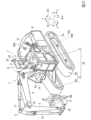
図1は、本発明の一実施形態に係る掘削計画作成装置100の構成例を示すブロック図である。図2は、図1に示す掘削計画作成装置100を搭載する作業機械としての油圧ショベル1の構成例を示す斜視図である。
Figure 1 is a block diagram showing an example of the configuration of an excavation
図1に示す掘削計画作成装置100は、例えば、マイクロコンピュータ、FPGA(Field Programmable Gate Array)等のコンピュータ、または、コンピュータとその周辺回路あるいは周辺装置等を用いて構成することができる。そして、掘削計画作成装置100は、コンピュータ、周辺回路、周辺装置等のハードウェアと、コンピュータが実行するプログラム等のソフトウェアとの組み合わせから構成される機能的構成として、土質推定部101と、地形情報推定部102と、地形情報取得部103と、計画値算出部104と、記憶部105を備える。本実施形態の掘削計画作成装置100は、例えば図2に示すように油圧ショベル1等の作業機械(掘削機械)に搭載される。油圧ショベル1は、図1に示す、掘削計画作成装置100と、地形情報を計測する地形計測部110と、油圧ショベル1の各部を制御する制御部120を備える。
The excavation
図2に示す油圧ショベル1は、本体部としての車両本体1Bと作業機2とを有する。車両本体1Bは、旋回体である上部旋回体3と走行体としての走行装置5とを有する。上部旋回体3は、機関室3EGの内部に、動力発生装置であるエンジンおよび油圧ポンプ等の装置を収容している。実施形態において、油圧ショベル1は、動力発生装置であるエンジンに、例えばディーゼルエンジン等の内燃機関が用いられるが、動力発生装置は内燃機関に限定されない。油圧ショベル1の動力発生装置は、例えば、内燃機関と発電電動機と蓄電装置とを組み合わせた、いわゆるハイブリッド方式の装置であってもよい。また、油圧ショベル1の動力発生装置は、内燃機関を有さず、蓄電装置と発電電動機とを組み合わせた装置であってもよい。
The
上部旋回体3は、運転室4を有する。図2に示す例において、運転室4は、上部旋回体3の機関室3EGが配置されている側とは反対の側に設置されている。ただし、運転室4と機関室3EGの位置関係はこの例に限定されない。上部旋回体3の上方には、手すり9が取り付けられている。
The upper rotating
走行装置5は、上部旋回体3を搭載する。走行装置5は、履帯5a、5bを有している。走行装置5は、左右に設けられた油圧モータ5cの一方または両方が駆動する。走行装置5の履帯5a、5bが回転することにより、油圧ショベル1を走行させる。作業機2は、上部旋回体3の運転室4の側方側に取り付けられている。
The traveling device 5 carries the upper rotating
油圧ショベル1は、履帯5a、5bの代わりにタイヤを備え、エンジンの駆動力を、トランスミッションを介してタイヤへ伝達して走行が可能な走行装置を備えたものであってもよい。このような形態の油圧ショベル1としては、例えば、ホイール式油圧ショベルがある。また、油圧ショベル1は、このようなタイヤを有した走行装置を備え、さらに車両本体(本体部)に作業機が取り付けられ、図2に示すような上部旋回体3およびその旋回機構を備えていない構造を有する、例えばバックホウローダであってもよい。すなわち、バックホウローダは、車両本体に作業機が取り付けられ、車両本体の一部を構成する走行装置を備えたものである。
The
上部旋回体3は、作業機2および運転室4が配置されている側が前であり、機関室3EGが配置されている側が後である。上部旋回体3の前後方向がy方向である。前に向かって左側が上部旋回体3の左であり、前に向かって右側が上部旋回体3の右である。上部旋回体3の左右方向は、幅方向またはx方向ともいう。油圧ショベル1または車両本体1Bは、上部旋回体3を基準として走行装置5側が下であり、走行装置5を基準として上部旋回体3側が上である。上部旋回体3の上下方向がz方向である。油圧ショベル1が水平面に設置されている場合、下は鉛直方向、すなわち重力の作用方向側であり、上は鉛直方向とは反対側である。
The side of the upper rotating
作業機2は、ブーム6とアーム7と作業具であるバケット8とブームシリンダ10とアームシリンダ11とバケットシリンダ12とを有する。ブーム6の基端部は、ブームピン13を介して車両本体1Bの前部に回動可能に取り付けられている。アーム7の基端部は、アームピン14を介してブーム6の先端部に回動可能に取り付けられている。アーム7の先端部には、バケットピン15を介してバケット8が取り付けられている。バケット8は、バケットピン15を中心として回動する。バケット8は、バケットピン15とは反対側に複数の刃8Bが取り付けられている。刃先8Tは、刃8Bの先端である。
The work machine 2 has a
バケット8は、複数の刃8Bを有していなくてもよい。つまり、図2に示されるような刃8Bを有しておらず、刃先が鋼板によってストレート形状に形成されたようなバケットであってもよい。作業機2は、例えば、単数の刃を有するチルトバケットを備えていてもよい。チルトバケットとは、バケットチルトシリンダを備え、バケットが左右にチルト傾斜することで油圧ショベルが傾斜地にあっても、斜面、平地を自由な形に成形したり、整地したりすることができ、底板プレートによる転圧作業もできるバケットである。この他にも、作業機2は、バケット8の代わりに、法面バケットまたは削岩用のチップを備えた削岩用のアタッチメント等を作業具として備えていてもよい。
The
図2に示されるブームシリンダ10とアームシリンダ11とバケットシリンダ12とは、それぞれ油圧ポンプから吐出される作動油の圧力によって駆動される油圧シリンダである。ブームシリンダ10はブーム6を駆動して、昇降させる。アームシリンダ11は、アーム7を駆動して、アームピン14の周りを回動させる。バケットシリンダ12は、バケット8を駆動して、バケットピン15の周りを回動させる。
The
また、作業機2は、図示していない第1ストロークセンサ、第2ストロークセンサおよび第3ストロークセンサを備えている。第1ストロークセンサはブームシリンダ10に、第2ストロークセンサはアームシリンダ11に、第3ストロークセンサはバケットシリンダ12に、それぞれ設けられる。第1ストロークセンサは、ブームシリンダ10の長さであるブームシリンダ長を検出して制御部120に出力する。第2ストロークセンサは、アームシリンダ11の長さであるアームシリンダ長を検出して制御部120に出力する。第3ストロークセンサは、バケットシリンダ12の長さであるバケットシリンダ長を検出して制御部120に出力する。
The work machine 2 also includes a first stroke sensor, a second stroke sensor, and a third stroke sensor, which are not shown. The first stroke sensor is provided on the
ブームシリンダ長、アームシリンダ長及びバケットシリンダ長が決定されれば、作業機2の姿勢が決定される。したがって、これらを検出する第1ストロークセンサ、第2ストロークセンサおよび第3ストロークセンサは、作業機2の姿勢を検出する姿勢検出装置に相当する。姿勢検出装置は、第1ストロークセンサ、第2ストロークセンサおよび第3ストロークセンサに限定されるものではなく、角度検出器であってもよい。 Once the boom cylinder length, arm cylinder length, and bucket cylinder length are determined, the posture of the work machine 2 is determined. Therefore, the first stroke sensor, second stroke sensor, and third stroke sensor that detect these correspond to a posture detection device that detects the posture of the work machine 2. The posture detection device is not limited to the first stroke sensor, second stroke sensor, and third stroke sensor, and may be an angle detector.
制御部120は、第1ストロークセンサが検出したブームシリンダ長から、油圧ショベル1の座標系であるローカル座標系における水平面と直交する方向(z軸方向)に対するブーム6の傾斜角を算出する。制御部120は、また、第2ストロークセンサが検出したアームシリンダ長から、ブーム6に対するアーム7の傾斜角を算出する。制御部120は、また、第3ストロークセンサが検出したバケットシリンダ長から、アーム7に対するバケット8の傾斜角を算出する。ブーム6、アーム7およびバケット8の傾斜角は、作業機2の姿勢を示す情報である。
The
上部旋回体3の上部には、アンテナ21、22が取り付けられている。アンテナ21、22は、油圧ショベル1の現在位置を検出するために用いられる。アンテナ21、22は、制御部120(またはその周辺回路)に接続されている。制御部120(またはその周辺回路)は、アンテナ21、22を用いて、RTK-GNSS(Real Time Kinematic - Global Navigation Satellite Systems、GNSSは全地球航法衛星システムをいう)による電波を受信し、油圧ショベル1の現在位置を検出する。アンテナ21、22が受信したGNSS電波に応じた信号は、制御部120に入力され、グローバル座標系におけるアンテナ21、22の設置位置が算出される。全地球航法衛星システムの一例としては、GPS(Global Positioning System)が挙げられるが、全地球航法衛星システムは、これに限定されるものではない。
アンテナ21、22は、図2に示されるように、上部旋回体3の上であって、油圧ショベル1の左右方向、すなわち幅方向に離れた両端位置に設置されることが好ましい。実施形態において、アンテナ21、22は、上部旋回体3の幅方向両側にそれぞれ取り付けられた手すり9に取り付けられる。アンテナ21、22が上部旋回体3に取り付けられる位置は手すり9に限定されるものではないが、アンテナ21、22は、可能な限り離れた位置に設置される方が、油圧ショベル1の現在位置の検出精度は向上するので好ましい。また、アンテナ21、22は、オペレータの視界を極力妨げない位置に設置されることが好ましい。
As shown in FIG. 2, the
また、油圧ショベル1は、撮像装置19を備える。撮像装置19は、例えば、ステレオカメラであり、例えば油圧ショベル1の作業対象の領域を撮像し、撮像した画像を撮像装置19が備える地形計測部110に出力する。地形計測部110は、撮像装置19が撮影した視差画像に基づき、3次元の地形情報を作成して計測地形情報として掘削計画作成装置100へ出力する。撮像装置19は、例えば、上部旋回体3の運転室4の上方に設置される。ただし、撮像装置19が設置される場所は運転席4の上方に限定されるものではない。例えば、撮像装置19は、運転室4の内部かつ上方に設置されてもよい。なお、地形計測部110は、撮像装置19に代えて、あるいは、とともに、三次元レーザーレンジファインダ、三次元レーザースキャナ、三次元距離センサ等を用いて地形情報を作成してもよい。
The
図1に戻り、地形計測部110は、3次元の地形情報を表す計測地形情報を作成して、掘削計画作成装置100へ例えば所定周期毎に出力する。
Returning to FIG. 1, the
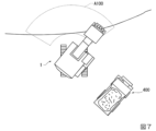
また、制御部120は、掘削計画作成装置100から掘削計画に基づく計画値を入力して作業機2と上部旋回体3を制御するとともに、刃先8Tの位置(3次元位置)と作業機2の負荷を表す時系列データを掘削計画作成装置100へ出力する。ここで作業機2の負荷は、一般的にシリンダ圧やポンプ圧により計測される。本実施形態においては、作業機2の負荷は、例えば各シリンダ10~12の負荷圧等で表すことができ、掘削時の負荷(掘削負荷)と非掘削時(旋回時等)の負荷とを含む。また、掘削負荷は掘削抵抗を指す。掘削計画は、例えば、図7に示すに一定範囲内A100を目標土量や目標地形となるまで掘削する計画であり、計画値は掘削軌跡と旋回方向を表す情報であり、例えば目標軌跡、掘削開始点等のデータからなる旋回分を含む3次元情報である。図7は、図2に示す油圧ショベル1の動作例(一定範囲内A100を掘削し、掘削物をダンプトラック400に積み込む際の動作例)を模式的に示す平面図である。
The
土質推定部101は、制御部120から入力した刃先位置と負荷を表す時系列データと、後述する計画値算出部104が算出した計画値とを入力し、計画値が指示する刃先位置の軌跡(計画軌跡という)と実際の刃先の軌跡のずれに基づいて土質を推定する。本実施形態において計画値は、土質の推定結果に基づいて算出される。したがって、推定している土質と実際の土質とに差がある場合、計画軌跡と実際の軌跡とのずれが大きくなる傾向がある。例えば図4に示すように、計画軌跡201と実際の軌跡203のずれが、計画軌跡201と実際の軌跡204のずれより大きい場合、実際の軌跡203が得られたときの土質の推定結果は、実際の軌跡204が得られたときの土質の推定結果より、推定値と実際の値との差が大きかったということが分かる。そこで、土質推定部101は、計画軌跡と実際の刃先位置の軌跡のずれに基づいて、例えば、計画値より実際の軌跡が浅い場合には実際の土質は推定土質より掘削抵抗が大きい土質であると推定することができ、計画値と実際の軌跡の差が小さい場合には実際の土質は推定土質に近い土質であると推定することができる。なお、土質は、例えば、土、砂、粘土等の種別で表されていてもよいし、掘削抵抗や水分の含有量等の値あるいは値に基づく指標値などで表されていてもよい。なお、図4は、図1に示す土質推定部101の動作例を説明するための模式図であり、掘削面200と計画軌跡201と実際の軌跡(の例)203および204の断面図を模式的に示す。
The soil
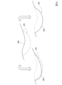
地形情報推定部102は、制御部120から入力した刃先位置と負荷を表す時系列データと、土質推定部101が推定した土質とを入力し、3次元の地形情報を推定して、推定地形情報として地形情報取得部103へ出力する。地形情報推定部102は、例えば、地形情報計測部110が取得した計測地形情報を初期値(あるいは基準値)として、制御部120から入力した刃先位置を表す時系列データと、土質推定部101が推定した土質に基づいて、地形情報を推定する。あるいは、地形情報推定部102は、例えば、事前の空撮画像等に基づき作成された地形情報を初期値(あるいは基準値)としてもよい。この場合、例えば、地形計測部110を省略することができる。地形情報推定部102は、例えば、図5に示すように、掘削前の掘削面211に対して、掘削時の実際の刃先の軌跡が軌跡212として得られた場合、掘削後地形が掘削軌跡212に等しいものと仮定する(掘削軌跡212より上にある土が無くなる)。次に、地形情報推定部102は、バケットからのこぼれ土量の推定値を軌跡212に基づく現況地形に加算して加算後の地形213を求める。次に、地形情報推定部102は、くずれ量を想定して、移動平均によるスムージングを掛けて地形214を算出する。なお、こぼれ土量やくずれ量は、例えば切り取り土量の一定割合とすることができ、また、こぼれ土量やくずれ量は土質に応じて変化させることができる。また、移動平均は土の変化があった周辺のみとすることができる。なお、地形情報は、3次元情報として算出されるので、例えばガウシアンフィルタ等を用いてスムージング処理を行ってもよい。なお、図5は、図1に示す地形情報推定部102の動作例を説明するための模式図であり、掘削面211と実際の軌跡(の例)212と推定された地形213および214の断面図を模式的に示す。
The topographical
地形情報取得部103は、計測地形情報と推定地形情報を入力(取得)し、計測地形情報が地形計測部110から正常に取得できる場合には計測地形情報を選択して地形情報として計画値算出部104へ出力する。また、地形情報取得部103は、計測地形情報が地形計測部110から正常に取得できない場合には推定地形情報を選択して地形情報として計画値算出部104へ出力する。
The terrain
一方、記憶部105は、計画モデル106を複数、記憶する。複数の計画モデル106は、例えば作業機械1を基準とする一定の範囲内で目標土量や目標地形(例えば掘削後の斜面形状)となるまでの掘削計画を作成する際に、地形情報を入力し、掘削軌跡と旋回方向の計画値を出力する機械学習モデルであって、掘削効率を評価値として土質に係るパラメータをそれぞれ異ならせて機械学習された機械学習モデルである。計画モデル106は、例えば、ニューラルネットワークを要素とする学習済みモデルであり、入力される多数のデータに対して求める解が出力されるよう、機械学習によりニューラルネットワークの各層のニューロン間の重み付け係数が最適化されている。計画モデル106は、例えば、入力から出力までの演算を行うプログラムと当該演算に用いられる重み付け係数(パラメータ)の組合せで構成される。ここで、図6を参照して、計画モデル106の学習の仕方について説明する。
On the other hand, the
図6は、図1に示す計画モデル106の学習の仕方の一例を示す模式図である。図6に示す例では、計画モデル106は、強化学習によって機械学習される。計画モデル106は、掘削シミュレータ301で生成された地形情報(掘削後地形302)を入力し、出力した掘削軌跡および旋回方向303を掘削シミュレータ301へ入力する。掘削シミュレータ301は、地形モデル305と、車体モデルおよび制御モデル307を含む。地形モデル305はパラメータとして土質304を入力するとともに刃先通過軌跡308を入力し、掘削後地形302と掘削抵抗306と掘削土量310を出力する。車体モデルおよび制御モデル307は、掘削軌跡および旋回方向303と掘削抵抗306を入力し、刃先通過軌跡308と掘削時間および旋回時間309を出力する。強化学習アルゴリズム312は、評価311において算出した掘削作業の効率を評価値として、既存の強化学習アルゴリズムの手法によって計画モデル106をアップデートする。なお、掘削作業の効率は、例えば、掘削土量を作業時間(=掘削時間+旋回時間)で除することで求めることができる。また、評価311においては、掘削計画における目標地形(例えば掘削範囲と掘削形状の目標値)に適合する掘削に対して評価値を高め、目標地形に適合しない掘削に対して評価値を低める処理を行う。例えば、目標地形として、掘削範囲外の掘削は禁止(マス堀り)、かつ、手前に60度の斜面をなるべく残すという条件が与えられた場合、範囲外の掘削には報酬を与えず、60度の斜面を崩す掘削には範囲内の掘削に対する報酬の数~数十分の一の報酬を与えるといった評価を行って、報酬(評価値)を算出する。なお、地形モデル305は、土質304が変化した場合に、掘削後地形302と掘削抵抗306と掘削土量310の少なくとも1つが変化するモデルとする。1つの計画モデル106の機械学習では、土質304の値は固定とする。この場合、各計画モデル106は、土質304の値に対応するモデルとなる。
Figure 6 is a schematic diagram showing an example of how the
また、計画値算出部104は、土質推定部101が推定した土質に基づき計画モデル106を選択し、選択した計画モデル106に、地形情報取得部103が取得(出力)した地形情報を入力し、計画モデル106の出力として計画値を算出する。その際、計画値算出部104は、例えばオペレータが設定した掘削計画(目標土量や目標形状)と、学習時の掘削計画(目標土量や目標形状)の設定とが等しい計画モデル106を選択する。
The planned value calculation unit 104 also selects a
次に、図3を参照して、図1に示す掘削計画作成装置100の動作例について説明する。図3は、図1に示す掘削計画作成装置100の動作例を示すフローチャートである。
Next, an example of the operation of the drilling
例えば、油圧ショベル1のオペレータが、油圧ショベル1を掘削の開始位置まで移動させ、掘削方向を所定の方向に調整した後、自動掘削の開始を指示すると、掘削計画作成装置100は、以後、自動掘削の終了条件が成立するまで(ステップS6で「YES」になるまで)、ステップ2~ステップS6の処理を所定の周期で繰り返し実行する(「開始」~ステップS1で「YES」)。ステップS2では、地形情報取得部103が、地形計測部110が出力した計測地形情報または地形情報推定部102が出力した推定地形情報の一方を、地形情報として取得して計画値算出部104へ出力する。次に、土質推定部101が土質を推定する(ステップS3)。次に、計画値算出部104が土質とオペレータが設定した掘削計画(目標土量や目標形状)に基づき、記憶部105から計画モデル106を選択する(ステップS4)。次に、計画値算出部104が、選択した計画モデル106に地形形状を入力し、計画モデル106の出力として計画値を算出する(ステップS5)。次に、掘削計画作成装置100(例えば計画値算出部104)が、終了条件を満たすか否か(例えば掘削計画が完了したか否か)を判定する(ステップS6)。
For example, when the operator of the
以上の処理によって、掘削計画作成装置100は、掘削計画に基づき油圧ショベル1を自動制御することができる。その際、土質に合わせて計画モデル106が選択されるので、掘削計画作成装置100は、掘削計画を作成する(掘削計画に基づき計画値を算出する)際に、土質の影響を適切に考慮することができる。
By the above processing, the excavation
以上、この発明の実施形態について図面を参照して説明してきたが、具体的な構成は上記実施形態に限られるものではなく、この発明の要旨を逸脱しない範囲の設計変更等も含まれる。例えば、計画モデル106を作成する際には、土質に加えて、例えば、掘削深さの制限値をパラメータとして車体モデルおよび制御モデル307に対して入力するようにしてもよい。例えば、土質を土と砂の2種類、掘削深さの制限値を1m、80cm、60cmの3種類に変化させて、強化学習を行えば、6種類の計画モデル106を作成することができる。また、機械学習の仕方は、強化学習に限定されず、例えば、教師あり学習としてもよい。また、計画値算出部104が算出した計画値は、制御部120へ出力するのに代えて、オペレータが目標値として視認できる表示形態で所定の表示部に出力するようにしてもよい。
Although the embodiment of the present invention has been described above with reference to the drawings, the specific configuration is not limited to the above embodiment, and design changes within the scope of the present invention are also included. For example, when creating the
また、上記実施形態でコンピュータが実行するプログラムの一部または全部は、コンピュータ読取可能な記録媒体や通信回線を介して頒布することができる。 In addition, some or all of the programs executed by the computer in the above embodiments can be distributed via computer-readable recording media or communication lines.
1 油圧ショベル(作業機械)、100 掘削計画作成装置、102 地形情報推定部、103 地形情報取得部、104 計画値算出部、105 記憶部、106 計画モデル 1 Hydraulic excavator (working machine), 100 Excavation plan creation device, 102 Terrain information estimation unit, 103 Terrain information acquisition unit, 104 Plan value calculation unit, 105 Memory unit, 106 Plan model
Claims (10)
土質を推定する土質推定部と、
地形情報を取得する地形情報取得部と、
前記土質推定部が推定した土質に基づき前記計画モデルを選択し、選択した前記計画モデルに、前記地形情報取得部が取得した地形情報を入力し、前記計画モデルの出力として前記計画値を算出する計画値算出部と、
を備え、
前記土質推定部は、前記計画値算出部が算出した計画値が指示するバケットの刃先位置の計画軌跡と、前記バケットの実際の刃先の軌跡のずれに基づいて土質を推定する、
掘削計画作成装置。 A machine learning model that inputs topographical information and outputs planned values of an excavation trajectory and a turning direction, the machine learning model being generated by machine learning with different parameters related to soil quality; and a memory unit that stores a plurality of planning models.
A soil quality estimation unit that estimates soil quality;
A topographical information acquisition unit that acquires topographical information;
a planning value calculation unit that selects the planning model based on the soil quality estimated by the soil quality estimation unit, inputs the topographical information acquired by the topographical information acquisition unit to the selected planning model, and calculates the planning value as an output of the planning model;
Equipped with
The soil quality estimation unit estimates soil quality based on a deviation between a planned trajectory of a blade tip position of a bucket indicated by the planned value calculated by the planned value calculation unit and an actual trajectory of the blade tip of the bucket.
Drilling planning device.
請求項1に記載の掘削計画作成装置。 The planning model is machine-learned by reinforcement learning using excavation efficiency as an evaluation value.
The drilling plan creating device according to claim 1.
請求項1または2に記載の掘削計画作成装置。3. The excavation plan creating device according to claim 1 or 2.
前記地形情報取得部が、前記地形情報推定部によって推定された前記地形情報を取得する、
請求項1から3のいずれか1項に記載の掘削計画作成装置。 A topographical information estimation unit is further provided that estimates the topographical information based on time-series data of a blade position of a bucket and a load of a work machine supporting the bucket, and the soil quality estimated by the soil quality estimation unit,
the topographical information acquisition unit acquires the topographical information estimated by the topographical information estimation unit;
The excavation plan creating device according to any one of claims 1 to 3 .
請求項4に記載の掘削計画作成装置。The excavation plan creating device according to claim 4.
請求項5に記載の掘削計画作成装置。The excavation plan creating device according to claim 5.
請求項6に記載の掘削計画作成装置。The excavation plan creating device according to claim 6.
を備える作業機械。 The excavation plan creation device according to any one of claims 1 to 7,
A work machine comprising:
土質を推定する土質推定部と、A soil quality estimation unit that estimates soil quality;
地形情報を取得する地形情報取得部と、A topographical information acquisition unit that acquires topographical information;
前記土質推定部が推定した土質に基づき前記計画モデルを選択し、選択した前記計画モデルに、前記地形情報取得部が取得した地形情報を入力し、前記計画モデルの出力として前記計画値を算出する計画値算出部と、a planning value calculation unit that selects the planning model based on the soil quality estimated by the soil quality estimation unit, inputs the topographical information acquired by the topographical information acquisition unit to the selected planning model, and calculates the planning value as an output of the planning model;
バケットの刃先位置と前記バケットを支持する作業機の負荷の時系列データと、前記土質推定部が推定した土質とに基づき、前記地形情報を推定する地形情報推定部と、を備え、a topographical information estimation unit that estimates the topographical information based on time-series data of a blade position of a bucket and a load of a work machine supporting the bucket, and the soil quality estimated by the soil quality estimation unit,
前記地形情報取得部が、前記地形情報推定部によって推定された前記地形情報を取得する、the topographical information acquisition unit acquires the topographical information estimated by the topographical information estimation unit;
掘削計画作成装置。Drilling planning device.
土質を推定するステップと、
地形情報を取得するステップと、
推定した土質に基づき前記計画モデルを選択し、選択した前記計画モデルに、取得した地形情報を入力し、前記計画モデルの出力として前記計画値を算出するステップと、
を含み、
前記土質を推定するステップでは、前記計画値を算出するステップで算出した計画値が指示するバケットの刃先位置の計画軌跡と、前記バケットの実際の刃先の軌跡のずれに基づいて土質を推定する、
掘削計画作成方法。 A machine learning model that inputs topographical information and outputs planned values of an excavation trajectory and a turning direction, the machine learning model being trained by varying parameters related to soil quality with excavation efficiency as an evaluation value, and storing a plurality of planned models;
estimating soil quality;
acquiring topographical information;
A step of selecting the planning model based on the estimated soil quality, inputting the acquired topographical information into the selected planning model, and calculating the planning value as an output of the planning model;
Including,
In the step of estimating soil type, soil type is estimated based on a deviation between a planned trajectory of a blade tip position of a bucket indicated by the planned value calculated in the step of calculating the planned value and an actual trajectory of the blade tip of the bucket.
How to create a drilling plan.
Priority Applications (6)
| Application Number | Priority Date | Filing Date | Title |
|---|---|---|---|
| JP2020094297A JP7481908B2 (en) | 2020-05-29 | 2020-05-29 | Drilling plan creating device, work machine, and drilling plan creating method |
| CN202180037582.9A CN115667636A (en) | 2020-05-29 | 2021-05-14 | Excavation plan creation device, work machine, and excavation plan creation method |
| KR1020227041024A KR20220162186A (en) | 2020-05-29 | 2021-05-14 | Excavation plan creation device, working machine and excavation plan creation method |
| PCT/JP2021/018324 WO2021241258A1 (en) | 2020-05-29 | 2021-05-14 | Excavation plan creation device, working machine, and excavation plan creation method |
| DE112021001941.4T DE112021001941T5 (en) | 2020-05-29 | 2021-05-14 | Excavation plan generation device, work machine, and excavation plan generation method |
| US17/999,591 US12523017B2 (en) | 2020-05-29 | 2021-05-14 | Excavation plan creation device, working machine, and excavation plan creation method |
Applications Claiming Priority (1)
| Application Number | Priority Date | Filing Date | Title |
|---|---|---|---|
| JP2020094297A JP7481908B2 (en) | 2020-05-29 | 2020-05-29 | Drilling plan creating device, work machine, and drilling plan creating method |
Publications (2)
| Publication Number | Publication Date |
|---|---|
| JP2021188362A JP2021188362A (en) | 2021-12-13 |
| JP7481908B2 true JP7481908B2 (en) | 2024-05-13 |
Family
ID=78744030
Family Applications (1)
| Application Number | Title | Priority Date | Filing Date |
|---|---|---|---|
| JP2020094297A Active JP7481908B2 (en) | 2020-05-29 | 2020-05-29 | Drilling plan creating device, work machine, and drilling plan creating method |
Country Status (6)
| Country | Link |
|---|---|
| US (1) | US12523017B2 (en) |
| JP (1) | JP7481908B2 (en) |
| KR (1) | KR20220162186A (en) |
| CN (1) | CN115667636A (en) |
| DE (1) | DE112021001941T5 (en) |
| WO (1) | WO2021241258A1 (en) |
Families Citing this family (14)
| Publication number | Priority date | Publication date | Assignee | Title |
|---|---|---|---|---|
| US20220081878A1 (en) * | 2020-09-11 | 2022-03-17 | Deere & Company | Grading machines with improved control |
| EP4194988B1 (en) | 2021-12-12 | 2024-03-06 | Caterpillar Inc. | System and method for generating a work plan for autonomous operation of a compactor |
| JP7713410B2 (en) * | 2022-02-24 | 2025-07-25 | 日立建機株式会社 | Work position indication system |
| WO2023190877A1 (en) * | 2022-03-31 | 2023-10-05 | 住友重機械工業株式会社 | Assistance device, work machine, program |
| JP7798248B2 (en) * | 2022-03-31 | 2026-01-14 | 住友重機械工業株式会社 | Support devices, work machines, and programs |
| JP7799952B2 (en) * | 2022-03-31 | 2026-01-16 | 住友重機械工業株式会社 | Support devices, work machines, and programs |
| JP2024000755A (en) | 2022-06-21 | 2024-01-09 | コベルコ建機株式会社 | Excavation route generation system |
| EP4605608A1 (en) * | 2022-10-19 | 2025-08-27 | Kinematic ApS | Ground material type identification |
| DK4389986T3 (en) * | 2022-12-20 | 2025-05-26 | Leica Geosystems Tech A/S | CONTROLLING AN EXCAVATION OPERATION BASED ON LOAD REGISTRATION |
| CN117488891A (en) * | 2023-11-24 | 2024-02-02 | 深圳海星智驾科技有限公司 | Excavator operating range setting method, terminal equipment and readable storage medium |
| WO2025126985A1 (en) * | 2023-12-14 | 2025-06-19 | 住友重機械工業株式会社 | Work machine, work machine management system, and work machine management device |
| WO2025181913A1 (en) * | 2024-02-27 | 2025-09-04 | 日本電気株式会社 | Control plan creation device and control plan creation method |
| WO2025181914A1 (en) * | 2024-02-27 | 2025-09-04 | 日本電気株式会社 | Control plan creation device and control plan creation method |
| JP2025175802A (en) * | 2024-05-20 | 2025-12-03 | 国立大学法人広島大学 | LOAD ESTIMATION DEVICE, LOAD ESTIMATION SYSTEM, LOAD ESTIMATION METHOD, AND LOAD ESTIMATION PROGRAM |
Citations (5)
| Publication number | Priority date | Publication date | Assignee | Title |
|---|---|---|---|---|
| US20130006484A1 (en) | 2010-02-23 | 2013-01-03 | Israel Aerospace Industries Ltd. | System and method of autonomous operation of multi-tasking earth moving machinery |
| JP2016130409A (en) | 2015-01-13 | 2016-07-21 | 株式会社小松製作所 | Excavation machine, excavation machine control method and excavation system |
| WO2019131979A1 (en) | 2017-12-27 | 2019-07-04 | 住友建機株式会社 | Excavator |
| WO2019189888A1 (en) | 2018-03-30 | 2019-10-03 | 住友重機械工業株式会社 | Construction machine operation assistance system, and construction machine |
| WO2020049821A1 (en) | 2018-09-05 | 2020-03-12 | 日立建機株式会社 | Work machine |
Family Cites Families (33)
| Publication number | Priority date | Publication date | Assignee | Title |
|---|---|---|---|---|
| US5461803A (en) * | 1994-03-23 | 1995-10-31 | Caterpillar Inc. | System and method for determining the completion of a digging portion of an excavation work cycle |
| US5603059A (en) * | 1994-04-22 | 1997-02-11 | Pitney Bowes Inc. | Software architecture system having a virtual I/O channel including multi-layered communication interface in between virtual stations and physical modules |
| US5493798A (en) * | 1994-06-15 | 1996-02-27 | Caterpillar Inc. | Teaching automatic excavation control system and method |
| US5528843A (en) * | 1994-08-18 | 1996-06-25 | Caterpillar Inc. | Control system for automatically controlling a work implement of an earthworking machine to capture material |
| US6047227A (en) * | 1996-11-19 | 2000-04-04 | Caterpillar Inc. | Method and apparatus for operating geography altering machinery relative to a work site |
| US6108949A (en) * | 1997-12-19 | 2000-08-29 | Carnegie Mellon University | Method and apparatus for determining an excavation strategy |
| WO2004027164A1 (en) * | 2002-09-17 | 2004-04-01 | Hitachi Construction Machinery Co., Ltd. | Excavation teaching apparatus for construction machine |
| US8775066B2 (en) * | 2006-07-05 | 2014-07-08 | Topcon Positioning Systems, Inc. | Three dimensional terrain mapping |
| US20090043462A1 (en) * | 2007-06-29 | 2009-02-12 | Kenneth Lee Stratton | Worksite zone mapping and collision avoidance system |
| US8351684B2 (en) * | 2008-02-13 | 2013-01-08 | Caterpillar Inc. | Terrain map updating system |
| US20090219199A1 (en) * | 2008-02-29 | 2009-09-03 | Caterpillar Inc. | Positioning system for projecting a site model |
| US8527155B2 (en) * | 2008-06-27 | 2013-09-03 | Caterpillar Inc. | Worksite avoidance system |
| US10248133B2 (en) * | 2011-06-27 | 2019-04-02 | Caterpillar Inc. | Method and system for mapping terrain and operating autonomous machines using machine parameters |
| US9378663B2 (en) * | 2011-06-27 | 2016-06-28 | Caterpillar Inc. | Method and system for mapping terrain using machine parameters |
| US9322148B2 (en) * | 2014-06-16 | 2016-04-26 | Caterpillar Inc. | System and method for terrain mapping |
| KR102528572B1 (en) | 2014-06-20 | 2023-05-02 | 스미도모쥬기가이고교 가부시키가이샤 | Shovel and Method for Controlling same |
| JP6462435B2 (en) * | 2015-03-13 | 2019-01-30 | 住友重機械工業株式会社 | Excavator |
| JP2017043885A (en) | 2015-08-24 | 2017-03-02 | 株式会社小松製作所 | Wheel loader |
| WO2017047695A1 (en) | 2015-09-16 | 2017-03-23 | 住友重機械工業株式会社 | Shovel |
| JP2018021345A (en) * | 2016-08-02 | 2018-02-08 | 株式会社小松製作所 | Work vehicle control system, control method, and work vehicle |
| EP4446501A3 (en) * | 2017-03-22 | 2025-02-19 | Sumitomo Heavy Industries, LTD. | Shovel, and management device and support device for shovels |
| JP6782270B2 (en) * | 2018-03-12 | 2020-11-11 | 日立建機株式会社 | Construction management system and work machine |
| US20200032490A1 (en) * | 2018-07-26 | 2020-01-30 | Built Robotics Inc. | Filling earth at a location within a dig site using an excavation vehicle |
| EP3848515B1 (en) * | 2018-09-03 | 2024-01-10 | Hitachi Construction Machinery Co., Ltd. | Work machine |
| JP7141899B2 (en) * | 2018-09-13 | 2022-09-26 | 日立建機株式会社 | working machine |
| JP6857409B2 (en) | 2018-12-12 | 2021-04-14 | 中国産業株式会社 | Pedestal seat, pedestal formation method, and garment with fan |
| CN113228139A (en) | 2019-05-24 | 2021-08-06 | 川崎重工业株式会社 | Construction machine with learning function |
| US10872466B1 (en) * | 2019-06-12 | 2020-12-22 | Trimble Inc. | Creating improved 3D models from 2D data |
| US11650595B2 (en) * | 2019-07-30 | 2023-05-16 | Caterpillar Inc. | Worksite plan execution |
| JP7402026B2 (en) * | 2019-11-27 | 2023-12-20 | 株式会社小松製作所 | Work machine control system, work machine, work machine control method |
| US11250300B2 (en) * | 2019-12-20 | 2022-02-15 | Cnh Industrial Canada, Ltd. | Detecting plugging of ground-engaging tools of an agricultural implement from imagery of a field using a machine-learned classification model |
| US20230263083A1 (en) * | 2022-02-23 | 2023-08-24 | Deere & Company | Proactive soil density detection system and method |
| US12324367B2 (en) * | 2022-12-09 | 2025-06-10 | Cnh Industrial America Llc | System and method for selectively activating soil sensors of an agricultural implement |
-
2020
- 2020-05-29 JP JP2020094297A patent/JP7481908B2/en active Active
-
2021
- 2021-05-14 WO PCT/JP2021/018324 patent/WO2021241258A1/en not_active Ceased
- 2021-05-14 KR KR1020227041024A patent/KR20220162186A/en not_active Ceased
- 2021-05-14 CN CN202180037582.9A patent/CN115667636A/en active Pending
- 2021-05-14 US US17/999,591 patent/US12523017B2/en active Active
- 2021-05-14 DE DE112021001941.4T patent/DE112021001941T5/en active Pending
Patent Citations (5)
| Publication number | Priority date | Publication date | Assignee | Title |
|---|---|---|---|---|
| US20130006484A1 (en) | 2010-02-23 | 2013-01-03 | Israel Aerospace Industries Ltd. | System and method of autonomous operation of multi-tasking earth moving machinery |
| JP2016130409A (en) | 2015-01-13 | 2016-07-21 | 株式会社小松製作所 | Excavation machine, excavation machine control method and excavation system |
| WO2019131979A1 (en) | 2017-12-27 | 2019-07-04 | 住友建機株式会社 | Excavator |
| WO2019189888A1 (en) | 2018-03-30 | 2019-10-03 | 住友重機械工業株式会社 | Construction machine operation assistance system, and construction machine |
| WO2020049821A1 (en) | 2018-09-05 | 2020-03-12 | 日立建機株式会社 | Work machine |
Also Published As
| Publication number | Publication date |
|---|---|
| US20230243130A1 (en) | 2023-08-03 |
| CN115667636A (en) | 2023-01-31 |
| DE112021001941T5 (en) | 2023-02-23 |
| JP2021188362A (en) | 2021-12-13 |
| US12523017B2 (en) | 2026-01-13 |
| WO2021241258A1 (en) | 2021-12-02 |
| KR20220162186A (en) | 2022-12-07 |
Similar Documents
| Publication | Publication Date | Title |
|---|---|---|
| JP7481908B2 (en) | Drilling plan creating device, work machine, and drilling plan creating method | |
| CN106029991B (en) | Work vehicle control system, control method, and work vehicle | |
| JP7404278B2 (en) | excavator | |
| US7865285B2 (en) | Machine control system and method | |
| JP7408761B2 (en) | Work machine control device and control method | |
| JP6096988B2 (en) | Work machine control device, work machine, and work machine control method | |
| JP7316052B2 (en) | SYSTEM INCLUDING WORK MACHINE AND COMPUTER IMPLEMENTED METHOD | |
| CN113107043A (en) | Controlling motion of a machine using sensor fusion | |
| JP7560973B2 (en) | Excavation information processing device, work machine, excavation support device, and excavation information processing method | |
| KR20210060866A (en) | Method and system for controlling construction machinery | |
| JP7312563B2 (en) | Work machine control system and control method | |
| JPWO2019187192A1 (en) | Work machine control systems, methods, and work machines | |
| JP7169760B2 (en) | WORK VEHICLE CONTROL SYSTEM, METHOD, AND WORK VEHICLE | |
| JP7382908B2 (en) | System and method for controlling work machines | |
| CN108779620B (en) | Work vehicle control system, control method, and work vehicle | |
| JP7379281B2 (en) | Systems, methods, and work machines for controlling work machines | |
| US12098526B2 (en) | System and method for automatically controlling work machine including work implement | |
| US12523004B2 (en) | Systems and methods for determining poor implement penetration | |
| JP2024065413A (en) | Control device, control method, and work machine | |
| JP2025075716A (en) | Work Machine | |
| WO2025183197A1 (en) | Work vehicle control system and work vehicle control method |
Legal Events
| Date | Code | Title | Description |
|---|---|---|---|
| A621 | Written request for application examination |
Free format text: JAPANESE INTERMEDIATE CODE: A621 Effective date: 20230414 |
|
| A131 | Notification of reasons for refusal |
Free format text: JAPANESE INTERMEDIATE CODE: A131 Effective date: 20240116 |
|
| A521 | Request for written amendment filed |
Free format text: JAPANESE INTERMEDIATE CODE: A523 Effective date: 20240314 |
|
| TRDD | Decision of grant or rejection written | ||
| A01 | Written decision to grant a patent or to grant a registration (utility model) |
Free format text: JAPANESE INTERMEDIATE CODE: A01 Effective date: 20240409 |
|
| A61 | First payment of annual fees (during grant procedure) |
Free format text: JAPANESE INTERMEDIATE CODE: A61 Effective date: 20240426 |
|
| R150 | Certificate of patent or registration of utility model |
Ref document number: 7481908 Country of ref document: JP Free format text: JAPANESE INTERMEDIATE CODE: R150 |