EP4194774A1 - Expansion valve - Google Patents
Expansion valve Download PDFInfo
- Publication number
- EP4194774A1 EP4194774A1 EP21853973.2A EP21853973A EP4194774A1 EP 4194774 A1 EP4194774 A1 EP 4194774A1 EP 21853973 A EP21853973 A EP 21853973A EP 4194774 A1 EP4194774 A1 EP 4194774A1
- Authority
- EP
- European Patent Office
- Prior art keywords
- valve
- valve body
- refrigerant
- space
- expansion valve
- Prior art date
- Legal status (The legal status is an assumption and is not a legal conclusion. Google has not performed a legal analysis and makes no representation as to the accuracy of the status listed.)
- Pending
Links
- 239000003507 refrigerant Substances 0.000 claims abstract description 73
- 238000004891 communication Methods 0.000 claims description 30
- XEEYBQQBJWHFJM-UHFFFAOYSA-N Iron Chemical group [Fe] XEEYBQQBJWHFJM-UHFFFAOYSA-N 0.000 description 16
- 230000002093 peripheral effect Effects 0.000 description 9
- 238000005057 refrigeration Methods 0.000 description 8
- 238000010438 heat treatment Methods 0.000 description 5
- 229920006395 saturated elastomer Polymers 0.000 description 5
- 238000004378 air conditioning Methods 0.000 description 4
- 238000005192 partition Methods 0.000 description 4
- 238000001816 cooling Methods 0.000 description 3
- 230000000149 penetrating effect Effects 0.000 description 3
- 230000001105 regulatory effect Effects 0.000 description 3
- 238000007789 sealing Methods 0.000 description 3
- 238000000638 solvent extraction Methods 0.000 description 3
- 239000013526 supercooled liquid Substances 0.000 description 3
- 229910000831 Steel Inorganic materials 0.000 description 2
- 239000010959 steel Substances 0.000 description 2
- 229910000976 Electrical steel Inorganic materials 0.000 description 1
- 238000007792 addition Methods 0.000 description 1
- 230000005540 biological transmission Effects 0.000 description 1
- 238000010586 diagram Methods 0.000 description 1
- 230000005284 excitation Effects 0.000 description 1
- 229910052742 iron Inorganic materials 0.000 description 1
- 239000007788 liquid Substances 0.000 description 1
- 239000000696 magnetic material Substances 0.000 description 1
- 239000000463 material Substances 0.000 description 1
- 239000007769 metal material Substances 0.000 description 1
- 239000011347 resin Substances 0.000 description 1
- 229920005989 resin Polymers 0.000 description 1
- 238000000926 separation method Methods 0.000 description 1
- 238000004781 supercooling Methods 0.000 description 1
- 230000007704 transition Effects 0.000 description 1
Images





Classifications
-
- F—MECHANICAL ENGINEERING; LIGHTING; HEATING; WEAPONS; BLASTING
- F25—REFRIGERATION OR COOLING; COMBINED HEATING AND REFRIGERATION SYSTEMS; HEAT PUMP SYSTEMS; MANUFACTURE OR STORAGE OF ICE; LIQUEFACTION SOLIDIFICATION OF GASES
- F25B—REFRIGERATION MACHINES, PLANTS OR SYSTEMS; COMBINED HEATING AND REFRIGERATION SYSTEMS; HEAT PUMP SYSTEMS
- F25B41/00—Fluid-circulation arrangements
- F25B41/30—Expansion means; Dispositions thereof
- F25B41/31—Expansion valves
- F25B41/34—Expansion valves with the valve member being actuated by electric means, e.g. by piezoelectric actuators
- F25B41/345—Expansion valves with the valve member being actuated by electric means, e.g. by piezoelectric actuators by solenoids
-
- F—MECHANICAL ENGINEERING; LIGHTING; HEATING; WEAPONS; BLASTING
- F25—REFRIGERATION OR COOLING; COMBINED HEATING AND REFRIGERATION SYSTEMS; HEAT PUMP SYSTEMS; MANUFACTURE OR STORAGE OF ICE; LIQUEFACTION SOLIDIFICATION OF GASES
- F25B—REFRIGERATION MACHINES, PLANTS OR SYSTEMS; COMBINED HEATING AND REFRIGERATION SYSTEMS; HEAT PUMP SYSTEMS
- F25B41/00—Fluid-circulation arrangements
- F25B41/30—Expansion means; Dispositions thereof
- F25B41/31—Expansion valves
- F25B41/32—Expansion valves having flow rate limiting means other than the valve member, e.g. having bypass orifices in the valve body
-
- F—MECHANICAL ENGINEERING; LIGHTING; HEATING; WEAPONS; BLASTING
- F25—REFRIGERATION OR COOLING; COMBINED HEATING AND REFRIGERATION SYSTEMS; HEAT PUMP SYSTEMS; MANUFACTURE OR STORAGE OF ICE; LIQUEFACTION SOLIDIFICATION OF GASES
- F25B—REFRIGERATION MACHINES, PLANTS OR SYSTEMS; COMBINED HEATING AND REFRIGERATION SYSTEMS; HEAT PUMP SYSTEMS
- F25B2341/00—Details of ejectors not being used as compression device; Details of flow restrictors or expansion valves
- F25B2341/06—Details of flow restrictors or expansion valves
-
- F—MECHANICAL ENGINEERING; LIGHTING; HEATING; WEAPONS; BLASTING
- F25—REFRIGERATION OR COOLING; COMBINED HEATING AND REFRIGERATION SYSTEMS; HEAT PUMP SYSTEMS; MANUFACTURE OR STORAGE OF ICE; LIQUEFACTION SOLIDIFICATION OF GASES
- F25B—REFRIGERATION MACHINES, PLANTS OR SYSTEMS; COMBINED HEATING AND REFRIGERATION SYSTEMS; HEAT PUMP SYSTEMS
- F25B2500/00—Problems to be solved
- F25B2500/01—Geometry problems, e.g. for reducing size
-
- F—MECHANICAL ENGINEERING; LIGHTING; HEATING; WEAPONS; BLASTING
- F25—REFRIGERATION OR COOLING; COMBINED HEATING AND REFRIGERATION SYSTEMS; HEAT PUMP SYSTEMS; MANUFACTURE OR STORAGE OF ICE; LIQUEFACTION SOLIDIFICATION OF GASES
- F25B—REFRIGERATION MACHINES, PLANTS OR SYSTEMS; COMBINED HEATING AND REFRIGERATION SYSTEMS; HEAT PUMP SYSTEMS
- F25B2500/00—Problems to be solved
- F25B2500/13—Vibrations
-
- Y—GENERAL TAGGING OF NEW TECHNOLOGICAL DEVELOPMENTS; GENERAL TAGGING OF CROSS-SECTIONAL TECHNOLOGIES SPANNING OVER SEVERAL SECTIONS OF THE IPC; TECHNICAL SUBJECTS COVERED BY FORMER USPC CROSS-REFERENCE ART COLLECTIONS [XRACs] AND DIGESTS
- Y02—TECHNOLOGIES OR APPLICATIONS FOR MITIGATION OR ADAPTATION AGAINST CLIMATE CHANGE
- Y02B—CLIMATE CHANGE MITIGATION TECHNOLOGIES RELATED TO BUILDINGS, e.g. HOUSING, HOUSE APPLIANCES OR RELATED END-USER APPLICATIONS
- Y02B30/00—Energy efficient heating, ventilation or air conditioning [HVAC]
- Y02B30/70—Efficient control or regulation technologies, e.g. for control of refrigerant flow, motor or heating
Definitions
- the present invention relates to an expansion valve used in an air conditioning system.
- An air conditioning system has a refrigeration cycle which mainly includes a compressor compressing a refrigerant to become superheated steam having a high temperature and a high pressure, a condenser cooling the refrigerant sent from the compressor to become a supercooled liquid having a high temperature and a high pressure, an expansion valve expanding the refrigerant sent from the condenser to become moist steam having a low temperature and a low pressure, and an evaporator heating the refrigerant sent from the expansion valve to become saturated steam and in which the refrigerant circulates in order of the compressor, the condenser, the expansion valve, and the evaporator.
- an expansion valve of Patent Citation 1 is an electronic expansion valve and is able to adjust a valve opening degree between a valve seat formed in a valve housing and a valve body by driving the valve body in a valve opening direction by an electromagnetic force of a solenoid against an urging force of an urging means. Further, a current value applied to the solenoid is set on the basis of the temperature or pressure of the refrigerant having passed through a condenser and a valve opening degree is adjusted, so that a supercooling degree of the condenser is maintained constant.
- Patent Citation 1 JP 2001-153498 A (page 3, FIG. 1 )
- Patent Citation 1 Since the expansion valve of Patent Citation 1 has a poppet valve structure in which a valve opening portion is closed by the valve body and the valve seat, the valve opening portion can be reliably closed.
- the refrigerant of a high-pressure primary pressure is supplied from the condenser to the valve opening portion, a force due to the pressure of the refrigerant is applied to the valve body in addition to a driving force of the solenoid in the valve opening direction.
- the valve opening degree with respect to the current value applied to the solenoid is slightly different depending on the pressure of the refrigerant.
- the present invention has been made by focusing on such a problem and an object of the present invention is to provide an expansion valve having a high valve opening adjustment accuracy.
- an expansion valve includes: a valve housing which is provided with an inlet port allowing a refrigerant from a condenser to pass therethrough and an outlet port allowing a refrigerant toward an evaporator to pass therethrough; a valve body which is driven by a solenoid; a valve seat on which the valve body sits; and an urging member configured to urge the valve body in a valve closing direction, wherein a space is formed on a valve opening direction side of the valve body, and the refrigerant on the valve closing direction side in relation to the valve body flows into the space.
- the refrigerant on the valve closing direction side in relation to the valve seat flows into the space on the valve opening direction side of the valve body, the influence on the operation of the valve body due to a differential pressure between the high-pressure primary pressure sent to the expansion valve and a low-pressure secondary pressure on the evaporator side during the operation of the air conditioning system is small. Further, since the valve body strokes accurately with respect to the current value, the valve opening adjustment accuracy by the valve body is high.
- the urging member is disposed in the space. According to this preferable configuration, since the urging member can be disposed by using the space into which the refrigerant flows, it is possible to compactly form the expansion valve.
- the outlet port is provided on the valve closing direction side in relation to the valve seat and a communication path is provided to communicate the space with the outlet port. According to this preferable configuration, the refrigerant of the secondary pressure on the evaporator side can flow from the outlet port formed in the valve housing into the space through the communication path.
- the communication path is formed in the valve body. According to this preferable configuration, since the communication path is formed in the valve body, it is possible to simply perform a processing operation compared to a case in which the communication path is formed in the valve housing.
- the space and the inlet port are partitioned by a bellows. According to this preferable configuration, it is possible to partition the space and the inlet port by a simple configuration.
- an effective pressure receiving area of the valve body is equal to an effective pressure receiving area of the bellows. According to this preferable configuration, since the pressure of the refrigerant applied to the valve body from both sides in the solenoid driving direction is canceled, the operation of the solenoid is not influenced by the pressure of the refrigerant. Therefore, it is possible to finely change the flow rate of the refrigerant sent to the evaporator by the valve opening degree adjusted by the balance with the electromagnetic force of the solenoid and the urging force of the urging member.
- FIGS. 1 to 4 An expansion valve according to a first embodiment of the present invention will be described with reference to FIGS. 1 to 4 .
- the left and right sides when viewed from the front side of FIG. 2 will be described as the left and right sides of the expansion valve.
- the left side of the paper surface in which a valve housing 10 of FIG. 2 is disposed will be described as the left side of the expansion valve and the right side of the paper surface in which a solenoid 80 is disposed will be described as the right side of the expansion valve.
- an expansion valve V1 according to the first embodiment of the present invention constitutes a refrigeration cycle R used in an air conditioning system of an automobile or the like together with a compressor C, an indoor heat exchanger H1, an outdoor heat exchanger H2, and the like.
- the refrigeration cycle R is configured to circulate the refrigerant in order of the compressor C, the heat exchanger H1, the expansion valve V1, and the heat exchanger H2 in a heating mode.
- the refrigerant becomes superheated steam having a high pressure and a high temperature by the compressor C, becomes a supercooled liquid having a high temperature and a high pressure by the heat exchange with indoor air using the heat exchanger H1, becomes moist steam having a low temperature and a low pressure by being depressurized from a high-pressure primary pressure to a low-pressure secondary pressure using the expansion valve V1, and becomes saturated steam by the heat exchange with outdoor air using the heat exchanger H2.
- the indoor air is heated by the heat exchange with the heat exchanger H1. That is, in the heating mode, the heat exchanger H1 serves as a condenser and the heat exchanger H2 serves as an evaporator.
- the refrigeration cycle R is configured to circulate the refrigerant in order of the compressor C, the heat exchanger H2, the expansion valve V1, and the heat exchanger H1 in a cooling mode.
- the refrigerant becomes superheated steam having a high temperature and a high pressure by the compressor C, becomes a supercooled liquid having a high temperature and a high pressure by the heat exchange with outdoor air using the heat exchanger H2, becomes moist steam having a low temperature and a low pressure by being depressurized from a high-pressure primary pressure to a low-pressure secondary pressure using the expansion valve V1, and becomes saturated steam by the heat exchange with indoor air using the heat exchanger H1.
- the indoor air is cooled by the heat exchange with the heat exchanger H1. That is, in the cooling mode, the heat exchanger H1 serves as an evaporator and the heat exchanger H2 serves as a condenser.
- the refrigeration cycle R is used for heating unless otherwise specified.
- the heat exchanger H1 is referred to as a condenser H1 and the heat exchanger H2 is referred to as an evaporator H2 on the basis of the heating mode.
- the expansion valve V1 is disposed between the condenser H1 and the evaporator H2.
- a current flowing through a coil 86 constituting the solenoid 80 is set on the basis of the temperature difference of the refrigerants at the inlet side and the outlet side of the evaporator H2.
- the valve opening degree of the expansion valve V1 is adjusted in accordance with this current, the pressure of the refrigerant having passed through a valve 50 is adjusted from a high-pressure primary pressure P1 to a relatively low-pressure secondary pressure P2 and the temperature of the refrigerant is also adjusted from a high temperature to a low temperature. Accordingly, all refrigerants which are supercooled liquids sent from the condenser H1 are adjusted to the dryness of the moist steam that can transition to the saturated steam after passing through the evaporator H2.
- the valve 50 includes a valve body 51 and a valve seat 10a formed on the inner peripheral surface of the valve housing 10 and when a tapered surface portion 51a formed at the axial right end portion of the valve body 51 comes into contact with and separates from the valve seat 10a, the valve 50 is opened and closed.
- the expansion valve V1 mainly includes the valve housing 10 which is formed of a metal material or a resin material, the valve body 51 which is disposed inside the valve housing 10, and the solenoid 80 which is connected to the valve housing 10 and applies a driving force to the valve body 51.
- the valve body 51 includes a concave portion 51b which is formed at the center portion to open toward the axial right side and an axial left end portion of a rod 52 disposed to penetrate the coil 86 of the solenoid 80 is press-fitted and fixed to the concave portion 51b.
- a communication path 51c is formed in the valve body 51 at a position deviating in the radial direction in relation to the concave portion 51b to penetrate in the axial direction.
- the communication path 51c is formed to have a constant cross-section.
- a plurality of the communication paths 51c may be provided. This case is preferable in that the refrigerant can be easily allowed to enter and exit.
- the valve housing 10 is provided with an outlet port 11 which communicates with the evaporator H2 and an inlet port 12 which communicates with the condenser H1.
- the outlet port 11 is formed on the axial right side in relation to the valve seat 10a, that is, the valve closing direction to be described later.
- the inlet port 12 is formed on the axial left side in relation to the valve seat 10a, that is, the valve opening direction to be described later.
- a primary pressure chamber 14, a secondary pressure chamber 13, a valve opening portion 15, and a concave portion 10d are provided inside the valve housing 10.
- the refrigerant having passed through the condenser H1 is supplied from the inlet port 12 to the primary pressure chamber 14.
- the refrigerant having passed through the valve 50 is supplied from the primary pressure chamber 14 to the secondary pressure chamber 13 and is output from the outlet port 11. Further, the outlet port 11 communicates with the secondary pressure chamber 13.
- the valve opening portion 15 is disposed between the secondary pressure chamber 13 and the primary pressure chamber 14 and the valve seat 10a is formed at the edge portion on the axial left side.
- the concave portion 10d is disposed on the axial left side in relation to the valve seat 10a and constitutes the primary pressure chamber 14.
- a bellows 18 which is an urging member configured to urge the valve body 51 toward the axial right side, that is, in the valve closing direction is disposed in the primary pressure chamber 14.
- the axial left end is hermetically fixed to the lid member 16 and the axial right end is hermetically fixed to the axial left end surface of the valve body 51. That is, a space S1 is formed by partitioning the inside of the valve housing 10 using the bellows 18, the lid member 16, and the valve body 51.
- the space S1 communicates with the secondary pressure chamber 13 through the communication path 51c and the refrigerant inside the secondary pressure chamber 13 flows into the space S1. That is, the bellows 18 substantially hermetically partitions the space S1 and the primary pressure chamber 14 in the closed state of the valve 50.
- a flange portion 82d of a center post 82 is inserted and fitted from the axial right side into a concave portion 10c which is formed at the axial right end of the valve housing 10 and recessed toward the axial left side and the center post 82 is integrally and substantially hermetically connected and fixed to the valve housing 10.
- a through-hole is formed on the bottom of the concave portion 10c of the valve housing 10 and the concave portion 10c can be called an annular step portion.
- the solenoid 80 mainly includes a casing 81 which includes an opening portion 81a opening toward the axial left side, the center post 82 which is inserted from the axial left side into the opening portion 81a of the casing 81, is fixed to the inner diameter side of the casing 81, and has a substantially cylindrical shape, the rod 52 which is inserted through the center post 82 and is disposed to be movable in a reciprocating manner in the axial direction, the valve body 51 which is press-inserted and fixed to the axial left end portion of the rod 52, a movable iron core 84 into which the axial right end portion of the rod 52 is inserted and fixed, and an excitation coil 86 which is wound on the outside of the center post 82 through a bobbin.
- the axial right end portion of the valve housing 10 is substantially hermetically inserted and fixed to a concave portion 81b which is formed at the axial left end of the casing 81 and is recessed toward the axial right side.
- the center post 82 includes a cylindrical portion 82b which is formed of a rigid body corresponding to a magnetic material such as iron or silicon steel, extends in the axial direction, and is provided with a through-hole 82c through which the rod 52 is inserted and the flange portion 82d which extends from the outer peripheral surface of the axial left end portion of the cylindrical portion 82b in the outer diameter direction and has an annular shape.
- valve housing 10 is substantially hermetically inserted and fixed to the concave portion 81b of the casing 81 while the axial right end surface of the flange portion 82d of the center post 82 comes into contact with the bottom surface of the concave portion 81b of the casing 81 from the axial left side. That is, the center post 82 is fixed by sandwiching the flange portion 82d between the bottom surface of the concave portion 81b of the casing 81 and the bottom surface of the concave portion 10c of the valve housing 10 from both sides in the axial direction.
- the refrigerant inside the space S1 is applied to the axial left end surface of the valve body 51 and the refrigerant inside the secondary pressure chamber 13 is applied to the axial right end surface of the valve body 51. Since the secondary pressure chamber 13 and the space S1 communicate with each other by the communication path 51c formed in the valve body 51, the refrigerant inside the secondary pressure chamber 13 on the valve closing direction side in relation to the valve body 51, that is, the refrigerant of the secondary pressure P2 supplied from the outlet port 11 to the evaporator H2 flows into the space S1.
- the axial left end surface of the valve body 51 is formed to be slightly larger than the axial right end surface. Accordingly, it is easy to maintain the valve 50 in a closed state even when a slight pressure difference is instantly generated between the pressure inside the space S1 and the pressure inside the secondary pressure chamber 13.
- the communication path 51c is a narrow through-hole, in other words, a through-hole having a narrow passage cross-sectional area, the refrigerant inside the space S1 does not easily and instantly move toward the secondary pressure chamber 13, is held inside the space S1, and easily maintains the valve 50 in a closed state when a slight pressure difference is instantly generated between the pressure inside the space S1 and the pressure inside the secondary pressure chamber 13.
- the refrigerant flowing into the space S1 and the secondary pressure chamber 13 is the refrigerant of the same secondary pressure P2 supplied from the outlet port 11 to the evaporator H2.
- the electromagnetic force F sol is applied to the valve body 51 toward the axial left side and the force F rod is applied thereto toward the axial right side. That is, the force F rod - F sol is applied to the valve body 51 with the right direction as positive.
- valve opening degree of the expansion valve V1 is adjusted by the balance with the electromagnetic force of the solenoid 80 and the urging force of the bellows 18. Accordingly, the refrigerant supplied from the inlet port 12 and passing through the condenser H1 is depressurized from the high-pressure primary pressure P1 to the low-pressure secondary pressure P2 and is supplied to the evaporator H2 through the outlet port 11.
- the space S1 is formed on the driving direction side of the solenoid 80 in relation to the valve body 51, that is, the valve opening direction side of the valve body 51 and the refrigerant of the secondary pressure chamber 13 having a pressure lower than that of the refrigerant of the primary pressure chamber 14 flows into the space S1, it is possible to reduce the influence of the differential pressure applied to both sides in the moving direction of the valve body 51 when the valve 50 is switched from the closed state to the open state. As a result, since the valve body 51 accurately strokes with respect to the current value applied to the solenoid 80, it is possible to accurately adjust the valve opening degree by the valve body 51.
- the expansion valve V1 is configured as a normal closed type in which the valve body 51 is urged in the valve closing direction of the valve 50 by the bellows 18, it is possible to open the valve 50 by instantly operating the valve body 51 and to promptly reduce the high-pressure primary pressure P1 to the low-pressure secondary pressure P2.
- the bellows 18 is disposed in the space S1, it is not necessary to ensure a space for disposing the urging member on the side of the solenoid 80 and to configure the expansion valve V1 in a compact size. Further, since the bellows 18 is disposed on the side opposite to the solenoid 80 in the valve body 51, it is possible to stabilize the operation of the valve body 51.
- valve body 51 is provided with the communication path 51c which communicates the space S1 with the outlet port 11 and the refrigerant of the secondary pressure P2 flows from the outlet port 11 formed in the valve housing 10 into the space S1 through the communication path 51c. Accordingly, for example, a port separated from the outlet port 11 does not need to be formed in the valve housing 10 or the lid member 16 and the structure of the expansion valve V1 can be simplified.
- the communication path 51c is formed to penetrate the valve body 51 in the axial direction, the communication path communicating the space S1 with the outlet port 11 can be simply processed compared to the case of forming the communication path in the valve housing 10.
- the space S1 and the inlet port 12 are substantially hermetically partitioned by the bellows 18, it is possible to prevent the refrigerant of the primary pressure P1 from flowing into the space S1 in the closed state of the valve 50.
- the secondary pressure P2 since it is possible to maintain the secondary pressure P2 inside the space S1 in the closed state of the valve 50, it is possible to reliably reduce the influence of the differential pressure applied to both sides in the moving direction of the valve body 51 when the valve 50 is switched from the closed state to the open state.
- the bellows 18 which partitions the space S1 and the inlet port 12 also functions as the urging member, it is possible to simply configure the expansion valve V1.
- the effective pressure receiving area A may be slightly larger than the effective pressure receiving area B (i.e., A > B)
- the closed state of the valve 50 may be reliably maintained
- the effective pressure receiving area B may be slightly larger than the effective pressure receiving area A (i.e., A ⁇ B)
- the valve 50 may be easily opened. That is, the influence due to the pressure of the refrigerant applied to both sides in the moving direction of the valve body 51 may be reduced.
- the bellows 18 also has a function of partitioning the space S1 and the primary pressure chamber 14 and a function as the urging member, but when the urging member for urging the valve body 51 in the valve closing direction is provided separately, the bellows 18 does not have the urging force.
- FIGS. 5 to 7 An expansion valve according to a second embodiment of the present invention will be described with reference to FIGS. 5 to 7 .
- the description of the overlapping configuration in the same configuration as that of the first embodiment will be omitted.
- a valve body 151 of a valve 150 is a tubular body having a through-hole 151b penetrating its center portion and an edge portion of an axial right end 151a sits on the valve seat 10a.
- the axial left end portion of the rod 52 is press-inserted and fixed while penetrating the through-hole 151b.
- the axial left end surface and the axial right end surface of the valve body 151 are formed to have the same diameter.
- the space S2 which is partitioned by the concave portion 10d, a lid member 161, and the valve body 151 is formed inside the valve housing 10. Further, the valve housing 10 is provided with an annular portion formed between the concave portion 10d and the inlet port 12 and extending toward the inner diameter side. The inner peripheral surface of the annular portion functions as a guide surface 10b on which the outer peripheral surface of the valve body 151 is substantially hermetically slidable.
- a minute gap is formed between the guide surface 10b and the outer peripheral surface of the valve body 151 due to the slight radial separation thereof, the valve body 151 is smoothly and relatively movable in the axial direction with respect to the valve housing 10, and the gap functions as a clearance seal which substantially hermetically partitions the space S2 and the primary pressure chamber 14.
- the secondary pressure chamber 13 and the space S2 communicate with each other by a communication path 151c formed in the valve body 151. That is, the refrigerant inside the secondary pressure chamber 13 flows into the space S2 through the communication path 151c. Further, a spring 17 which is an urging member for urging the valve body 151 toward the axial right side is disposed in the space S2.
- valve body 151 is further regulated from being separated from the valve seat 10a.
- movement of the valve body 151 may be regulated by allowing the axial left end of the rod 52 to contact a shaft portion protruding from the lid member 16 toward the right side.
- the guide surface 10b guiding the movement of the valve body 151 is formed in the valve housing 10 and the space S2 and the inlet port 12 are substantially hermetically partitioned by the clearance seal formed between the guide surface 10b and the outer peripheral surface of the valve body 151, it is possible to suppress the refrigerant of the primary pressure P1 from flowing into the space S2 in the closed state of the valve 150. In other words, since it is easy to hold the refrigerant of the secondary pressure P2 inside the space S2, it is possible to reliably reduce the differential pressure applied to the valve body 151 when the valve 150 is switched from the closed state to the open state.
- the space S2 and the inlet port 12 are substantially hermetically partitioned by the clearance seal formed between the guide surface 10b and the outer peripheral surface of the valve body 151, it is not necessary to separately provide a member for partitioning the space S2 and the inlet port 12 and it is possible to decrease the number of parts and to simplify the structure of the expansion valve V2.
- valve housing 10 is provided with the guide surface 10b through which the valve body 151 is inserted, the valve body 151 is guided to the guide surface 10b. Accordingly, it is possible to improve the operation accuracy of the valve body 151. Further, since the valve seat 10a and the guide surface 10b are integrally formed in the valve housing 10, it is possible to provide the expansion valve V2 that has a small number of parts and is miniaturized.
- the effective pressure receiving areas A' and B' of the valve body 151 are the same, the pressure F P1 of the refrigerant and the pressure F P2 of the refrigerant are canceled. That is, since the secondary pressure P2 applied to the valve body 151 from both sides in the driving direction of the solenoid 80 is canceled, the operation of the solenoid 80 is not influenced by the secondary pressure P2.
- the valve opening degree is adjusted by the balance with the electromagnetic force F sol of the solenoid 80 and the urging force F sp of the spring 17. Therefore, it is possible to finely change the flow rate of the refrigerant sent to the evaporator H2.
- an outlet port 111 is formed on the axial left side in relation to the valve seat 10a and an inlet port 121 is formed on the axial right side in relation to the valve seat 10a.
- a valve body 251 in the fourth embodiment includes a concave portion 251b which is formed at the center portion to open toward the axial right side and a spring 19 which urges a rod 252, disposed to penetrate the coil 86 of the solenoid 80, toward the axial right side is disposed in the concave portion 251b.
- the spring 19 the axial left end comes into contact with the bottom surface of the concave portion 251b and the axial right end comes into contact with the side surface on the axial left side of a flange portion 252a extending in the outer diameter direction from the outer peripheral surface of the axial left end portion of the rod 252.
- valve body 251 and the rod 252 are supported by the spring 19 while being separated from each other in the axial direction in a non-fastened state, it is possible to improve the vibration resistance of the valve body 251 and the rod 252. Specifically, even when a vibration occurs in the rod 252 constituting the solenoid 80 due to a disturbance or the like, the vibration is absorbed by the spring 19 and the transmission to the valve body 251 is suppressed. Accordingly, since the closed state of the expansion valve V4 is stabilized, the sealing property is improved and the valve leakage can be reduced.
- the valve body 51 in the fifth embodiment includes the concave portion 51b which is formed at the center portion to open toward the axial right side and an axial left end portion of a rod 352 disposed to penetrate the coil 86 of the solenoid 80 is inserted into the concave portion 51b.
- the axial left end portion of the rod 352 is formed on a substantially semispherical surface and comes into point contact with the bottom surface of the concave portion 51b.
- an axial right end surface is formed as a substantially semispherical surface and the axial left end of the rod 52 disposed to penetrate the coil 86 of the solenoid 80 comes into point contact with the center portion.
- the outer diameter portion 451a of the axial right end surface formed as a substantially semispherical surface of the valve body 451 sits on the valve seat 10a. Accordingly, since the outer diameter portion 451a reliably sits on the valve seat 10a even when the valve body 451 is tilted, the sealing property is improved and the valve leakage can be reduced.
- a portion sitting on the valve seat 10a in the valve body 451 may be formed by, for example, the tapered surface portion 51a as in the first embodiment.
- a valve body 551 in the seventh embodiment is formed as a steel ball which is fixed by caulking or press-fitting to a concave portion 552b opening toward the axial right side of an adapter 552 to which the axial right end of the bellows 18 is hermetically fixed and the axial left end of the rod 52 disposed to penetrate the coil 86 of the solenoid 80 comes into point contact with the spherical surface of the valve body 551 disposed inside the secondary pressure chamber 13.
- a communication path 516a penetrating in the axial direction is formed in a lid member 516 hermetically fixed to the axial left end of the bellows 18.
- the communication path 516a communicates with the evaporator H2 through an orifice (not shown) provided outside an expansion valve V7. That is, the refrigerant of the secondary pressure P2 supplied from the outlet port 11 to the evaporator H2 flows into the space S1 formed inside the bellows 18.
- the space S1 is formed on the driving direction side of the solenoid 80 in relation to the valve body 551, that is, the valve opening direction side of the valve body 551.
- the refrigerant of the secondary pressure chamber 13 having a pressure lower than that of the refrigerant of the primary pressure chamber 14 flows into the space S1 through the orifice (not shown) formed outside the expansion valve V7 and the communication path 516a formed in the lid member 516. Accordingly, when the valve 50 is switched from the closed state to the open state, the influence of the differential pressure applied to both sides in the moving direction of the valve body 551 is small and the valve body 551 accurately strokes with respect to the current value applied to the solenoid 80. In this way, it is possible to adjust the valve opening degree with high accuracy by the valve body 551.
- valve body 551 and the rod 52 are not fastened to each other and the axial left end of the rod 52 comes into point contact with the spherical surface of the valve body 551 disposed inside the secondary pressure chamber 13, the correction of the tilting during driving which is seen in the case of the surface contact does not occur even when the rod 52 or the valve body 551 is tilted. Therefore, it is possible to suppress the tilting of the movable iron core 84 or the rod 52 and an increase in the contact resistance between the these and the members constituting the solenoid 80 and to reduce the influence on the operability of the expansion valve V7.
- valve body 551 when the valve body 551 is pressed toward the axial right side, that is, in the valve closing direction by the urging force of the bellows 18 in a state in which an expansion valve V7 is not energized, that is, the valve 50 is closed, a spherical surface portion 551a of the valve body 551 sits on the valve seat 10a. Accordingly, since the spherical surface portion 551a reliably sits on the valve seat 10a even when the valve body 551 is tilted, the sealing property is improved and the valve leakage can be reduced.
- valve body 551 since the steel ball is used as the valve body 551, the valve body can be resistant to mechanical wear.
- valve body is formed as a member separated from the rod disposed to penetrate the coil of the solenoid, but the present invention is not limited thereto. That is, the valve body and the rod may be integrally formed with each other.
- valve seat is integrally formed with the valve housing, but the valve seat may be formed separately from the valve housing.
- valve seat and the guide surface are integrally formed on the inner peripheral surface of the valve housing, but the present invention is not limited thereto. That is, the valve housing including the valve seat and the valve housing including the guide surface may be formed as separate members.
- the guide surface is not limited to that formed in the valve housing and may be formed, for example, in a part of the through-hole of the center post.
- the urging member is disposed inside the space on the valve opening direction side of the valve body, but the urging member may be disposed at a position other than the space on the valve opening direction side of the valve body such as the solenoid side.
- the communication path may be formed in the valve housing.
- the configuration of the communication path may be omitted and the valve housing forming the space may be formed or a different port communicating with the evaporator may be formed in the lid member as in the seventh embodiment.
Landscapes
- Engineering & Computer Science (AREA)
- Physics & Mathematics (AREA)
- General Engineering & Computer Science (AREA)
- Mechanical Engineering (AREA)
- Thermal Sciences (AREA)
- Fluid Mechanics (AREA)
- Magnetically Actuated Valves (AREA)
- Electromagnetism (AREA)
- Temperature-Responsive Valves (AREA)
Abstract
Description
- The present invention relates to an expansion valve used in an air conditioning system.
- An air conditioning system has a refrigeration cycle which mainly includes a compressor compressing a refrigerant to become superheated steam having a high temperature and a high pressure, a condenser cooling the refrigerant sent from the compressor to become a supercooled liquid having a high temperature and a high pressure, an expansion valve expanding the refrigerant sent from the condenser to become moist steam having a low temperature and a low pressure, and an evaporator heating the refrigerant sent from the expansion valve to become saturated steam and in which the refrigerant circulates in order of the compressor, the condenser, the expansion valve, and the evaporator.
- For example, an expansion valve of Patent Citation 1 is an electronic expansion valve and is able to adjust a valve opening degree between a valve seat formed in a valve housing and a valve body by driving the valve body in a valve opening direction by an electromagnetic force of a solenoid against an urging force of an urging means. Further, a current value applied to the solenoid is set on the basis of the temperature or pressure of the refrigerant having passed through a condenser and a valve opening degree is adjusted, so that a supercooling degree of the condenser is maintained constant.
- Further, it is also known to adjust the dryness of moist steam so that all refrigerants become saturated steam after the refrigerants pass through an evaporator by adjusting a valve opening degree of an expansion valve on the basis of the temperature or pressure of the refrigerant before or after passing through the evaporator.
- Patent Citation 1:
JP 2001-153498 A FIG. 1 ) - Since the expansion valve of Patent Citation 1 has a poppet valve structure in which a valve opening portion is closed by the valve body and the valve seat, the valve opening portion can be reliably closed. However, since the refrigerant of a high-pressure primary pressure is supplied from the condenser to the valve opening portion, a force due to the pressure of the refrigerant is applied to the valve body in addition to a driving force of the solenoid in the valve opening direction. As a result, there is concern that the valve opening degree with respect to the current value applied to the solenoid is slightly different depending on the pressure of the refrigerant.
- The present invention has been made by focusing on such a problem and an object of the present invention is to provide an expansion valve having a high valve opening adjustment accuracy.
- In order to solve the foregoing problem, an expansion valve according to the present invention includes: a valve housing which is provided with an inlet port allowing a refrigerant from a condenser to pass therethrough and an outlet port allowing a refrigerant toward an evaporator to pass therethrough; a valve body which is driven by a solenoid; a valve seat on which the valve body sits; and an urging member configured to urge the valve body in a valve closing direction, wherein a space is formed on a valve opening direction side of the valve body, and the refrigerant on the valve closing direction side in relation to the valve body flows into the space. According to the aforesaid feature of the present invention, since the refrigerant on the valve closing direction side in relation to the valve seat flows into the space on the valve opening direction side of the valve body, the influence on the operation of the valve body due to a differential pressure between the high-pressure primary pressure sent to the expansion valve and a low-pressure secondary pressure on the evaporator side during the operation of the air conditioning system is small. Further, since the valve body strokes accurately with respect to the current value, the valve opening adjustment accuracy by the valve body is high.
- It may be preferable that the urging member is disposed in the space. According to this preferable configuration, since the urging member can be disposed by using the space into which the refrigerant flows, it is possible to compactly form the expansion valve.
- It may be preferable that the outlet port is provided on the valve closing direction side in relation to the valve seat and a communication path is provided to communicate the space with the outlet port. According to this preferable configuration, the refrigerant of the secondary pressure on the evaporator side can flow from the outlet port formed in the valve housing into the space through the communication path.
- It may be preferable that the communication path is formed in the valve body. According to this preferable configuration, since the communication path is formed in the valve body, it is possible to simply perform a processing operation compared to a case in which the communication path is formed in the valve housing.
- It may be preferable that the space and the inlet port are partitioned by a bellows. According to this preferable configuration, it is possible to partition the space and the inlet port by a simple configuration.
- It may be preferable that an effective pressure receiving area of the valve body is equal to an effective pressure receiving area of the bellows. According to this preferable configuration, since the pressure of the refrigerant applied to the valve body from both sides in the solenoid driving direction is canceled, the operation of the solenoid is not influenced by the pressure of the refrigerant. Therefore, it is possible to finely change the flow rate of the refrigerant sent to the evaporator by the valve opening degree adjusted by the balance with the electromagnetic force of the solenoid and the urging force of the urging member.
-
-
FIG. 1 is a schematic diagram showing a refrigeration cycle that adopts an expansion valve according to a first embodiment of the present invention. -
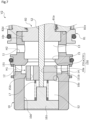
FIG. 2 is a cross-sectional view showing a structure of the expansion valve according to the first embodiment. -
FIG. 3 is a cross-sectional view showing a state in which the expansion valve according to the first embodiment is closed. -
FIG. 4 is a cross-sectional view showing a state in which the expansion valve according to the first embodiment is opened. -
FIG. 5 is a cross-sectional view showing a structure of an expansion valve according to a second embodiment of the present invention. -
FIG. 6 is a cross-sectional view showing a state in which the expansion valve according to the second embodiment is closed. -
FIG. 7 is a cross-sectional view showing a state in which the expansion valve according to the second embodiment is opened. -
FIG. 8 is a cross-sectional view showing a structure of an expansion valve according to a third embodiment of the present invention. -
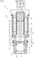
FIG. 9 is a cross-sectional view showing a structure of an expansion valve according to a fourth embodiment of the present invention. -
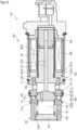
FIG. 10 is a cross-sectional view showing a structure of an expansion valve according to a fifth embodiment of the present invention. -
FIG. 11 is a cross-sectional view showing a structure of an expansion valve according to a sixth embodiment of the present invention. -
FIG. 12 is a cross-sectional view showing a structure of an expansion valve according to a seventh embodiment of the present invention. - Modes for carrying out an expansion valve according to the present invention will be described below with reference to embodiments.
- An expansion valve according to a first embodiment of the present invention will be described with reference to
FIGS. 1 to 4 . Hereinafter, the left and right sides when viewed from the front side ofFIG. 2 will be described as the left and right sides of the expansion valve. Specifically, the left side of the paper surface in which avalve housing 10 ofFIG. 2 is disposed will be described as the left side of the expansion valve and the right side of the paper surface in which asolenoid 80 is disposed will be described as the right side of the expansion valve. - As shown in
FIG. 1 , an expansion valve V1 according to the first embodiment of the present invention constitutes a refrigeration cycle R used in an air conditioning system of an automobile or the like together with a compressor C, an indoor heat exchanger H1, an outdoor heat exchanger H2, and the like. - First, the refrigeration cycle R will be described. The refrigeration cycle R is configured to circulate the refrigerant in order of the compressor C, the heat exchanger H1, the expansion valve V1, and the heat exchanger H2 in a heating mode. The refrigerant becomes superheated steam having a high pressure and a high temperature by the compressor C, becomes a supercooled liquid having a high temperature and a high pressure by the heat exchange with indoor air using the heat exchanger H1, becomes moist steam having a low temperature and a low pressure by being depressurized from a high-pressure primary pressure to a low-pressure secondary pressure using the expansion valve V1, and becomes saturated steam by the heat exchange with outdoor air using the heat exchanger H2. Accordingly, the indoor air is heated by the heat exchange with the heat exchanger H1. That is, in the heating mode, the heat exchanger H1 serves as a condenser and the heat exchanger H2 serves as an evaporator.
- Further, the refrigeration cycle R is configured to circulate the refrigerant in order of the compressor C, the heat exchanger H2, the expansion valve V1, and the heat exchanger H1 in a cooling mode. The refrigerant becomes superheated steam having a high temperature and a high pressure by the compressor C, becomes a supercooled liquid having a high temperature and a high pressure by the heat exchange with outdoor air using the heat exchanger H2, becomes moist steam having a low temperature and a low pressure by being depressurized from a high-pressure primary pressure to a low-pressure secondary pressure using the expansion valve V1, and becomes saturated steam by the heat exchange with indoor air using the heat exchanger H1. Accordingly, the indoor air is cooled by the heat exchange with the heat exchanger H1. That is, in the cooling mode, the heat exchanger H1 serves as an evaporator and the heat exchanger H2 serves as a condenser.
- In addition, in the following description, the refrigeration cycle R is used for heating unless otherwise specified. Similarly, the heat exchanger H1 is referred to as a condenser H1 and the heat exchanger H2 is referred to as an evaporator H2 on the basis of the heating mode.
- As shown in
FIGS. 1 and2 , the expansion valve V1 is disposed between the condenser H1 and the evaporator H2. A current flowing through acoil 86 constituting thesolenoid 80 is set on the basis of the temperature difference of the refrigerants at the inlet side and the outlet side of the evaporator H2. When the valve opening degree of the expansion valve V1 is adjusted in accordance with this current, the pressure of the refrigerant having passed through avalve 50 is adjusted from a high-pressure primary pressure P1 to a relatively low-pressure secondary pressure P2 and the temperature of the refrigerant is also adjusted from a high temperature to a low temperature. Accordingly, all refrigerants which are supercooled liquids sent from the condenser H1 are adjusted to the dryness of the moist steam that can transition to the saturated steam after passing through the evaporator H2. - In this embodiment, the
valve 50 includes avalve body 51 and avalve seat 10a formed on the inner peripheral surface of thevalve housing 10 and when atapered surface portion 51a formed at the axial right end portion of thevalve body 51 comes into contact with and separates from thevalve seat 10a, thevalve 50 is opened and closed. - Next, the structure of the expansion valve V1 will be described. As shown in
FIG. 2 , the expansion valve V1 mainly includes thevalve housing 10 which is formed of a metal material or a resin material, thevalve body 51 which is disposed inside thevalve housing 10, and thesolenoid 80 which is connected to thevalve housing 10 and applies a driving force to thevalve body 51. - As shown in
FIGS. 2 to 4 , thevalve body 51 includes aconcave portion 51b which is formed at the center portion to open toward the axial right side and an axial left end portion of arod 52 disposed to penetrate thecoil 86 of thesolenoid 80 is press-fitted and fixed to theconcave portion 51b. Further, acommunication path 51c is formed in thevalve body 51 at a position deviating in the radial direction in relation to theconcave portion 51b to penetrate in the axial direction. Thecommunication path 51c is formed to have a constant cross-section. In addition, a plurality of thecommunication paths 51c may be provided. This case is preferable in that the refrigerant can be easily allowed to enter and exit. - As shown in
FIGS. 2 to 4 , thevalve housing 10 is provided with anoutlet port 11 which communicates with the evaporator H2 and aninlet port 12 which communicates with the condenser H1. Theoutlet port 11 is formed on the axial right side in relation to thevalve seat 10a, that is, the valve closing direction to be described later. Further, theinlet port 12 is formed on the axial left side in relation to thevalve seat 10a, that is, the valve opening direction to be described later. - A
primary pressure chamber 14, asecondary pressure chamber 13, avalve opening portion 15, and aconcave portion 10d are provided inside thevalve housing 10. The refrigerant having passed through the condenser H1 is supplied from theinlet port 12 to theprimary pressure chamber 14. The refrigerant having passed through thevalve 50 is supplied from theprimary pressure chamber 14 to thesecondary pressure chamber 13 and is output from theoutlet port 11. Further, theoutlet port 11 communicates with thesecondary pressure chamber 13. Thevalve opening portion 15 is disposed between thesecondary pressure chamber 13 and theprimary pressure chamber 14 and thevalve seat 10a is formed at the edge portion on the axial left side. Theconcave portion 10d is disposed on the axial left side in relation to thevalve seat 10a and constitutes theprimary pressure chamber 14. - In the
concave portion 10d, an opening portion on the axial left side is closed by alid member 16. Further, a bellows 18 which is an urging member configured to urge thevalve body 51 toward the axial right side, that is, in the valve closing direction is disposed in theprimary pressure chamber 14. In thebellows 18, the axial left end is hermetically fixed to thelid member 16 and the axial right end is hermetically fixed to the axial left end surface of thevalve body 51. That is, a space S1 is formed by partitioning the inside of thevalve housing 10 using thebellows 18, thelid member 16, and thevalve body 51. - Further, the space S1 communicates with the
secondary pressure chamber 13 through thecommunication path 51c and the refrigerant inside thesecondary pressure chamber 13 flows into the space S1. That is, thebellows 18 substantially hermetically partitions the space S1 and theprimary pressure chamber 14 in the closed state of thevalve 50. - Further, a
flange portion 82d of acenter post 82 is inserted and fitted from the axial right side into aconcave portion 10c which is formed at the axial right end of thevalve housing 10 and recessed toward the axial left side and thecenter post 82 is integrally and substantially hermetically connected and fixed to thevalve housing 10. In addition, a through-hole is formed on the bottom of theconcave portion 10c of thevalve housing 10 and theconcave portion 10c can be called an annular step portion. - As shown in
FIG. 2 , thesolenoid 80 mainly includes acasing 81 which includes anopening portion 81a opening toward the axial left side, thecenter post 82 which is inserted from the axial left side into theopening portion 81a of thecasing 81, is fixed to the inner diameter side of thecasing 81, and has a substantially cylindrical shape, therod 52 which is inserted through thecenter post 82 and is disposed to be movable in a reciprocating manner in the axial direction, thevalve body 51 which is press-inserted and fixed to the axial left end portion of therod 52, amovable iron core 84 into which the axial right end portion of therod 52 is inserted and fixed, and anexcitation coil 86 which is wound on the outside of thecenter post 82 through a bobbin. - The axial right end portion of the
valve housing 10 is substantially hermetically inserted and fixed to aconcave portion 81b which is formed at the axial left end of thecasing 81 and is recessed toward the axial right side. - The
center post 82 includes acylindrical portion 82b which is formed of a rigid body corresponding to a magnetic material such as iron or silicon steel, extends in the axial direction, and is provided with a through-hole 82c through which therod 52 is inserted and theflange portion 82d which extends from the outer peripheral surface of the axial left end portion of thecylindrical portion 82b in the outer diameter direction and has an annular shape. - Further, the
valve housing 10 is substantially hermetically inserted and fixed to theconcave portion 81b of thecasing 81 while the axial right end surface of theflange portion 82d of thecenter post 82 comes into contact with the bottom surface of theconcave portion 81b of thecasing 81 from the axial left side. That is, thecenter post 82 is fixed by sandwiching theflange portion 82d between the bottom surface of theconcave portion 81b of thecasing 81 and the bottom surface of theconcave portion 10c of thevalve housing 10 from both sides in the axial direction. - Next, the opening and closing operation of the expansion valve V1 will be described.
- First, a state in which the expansion valve V1 is not energized will be described. As shown in
FIGS. 2 and3 , when thevalve body 51 is pressed toward the axial right side, that is, in the valve closing direction by the urging force of thebellows 18 in a state in which the expansion valve V1 is not energized, the taperedsurface portion 51a of thevalve body 51 sits on thevalve seat 10a to close thevalve 50. Specifically, the taperedsurface portion 51a of thevalve body 51 comes into contact with thevalve seat 10a formed in a tapered shape to expand toward the axial left side so that the tapered surface portion sits thereon. - At this time, when the effective pressure receiving area of the
bellows 18 is A and the effective pressure receiving area of thevalve body 51 is B, the urging force Fbel of thebellows 18, the force FP1 = P1 × (A - B) due to the primary pressure P1 of the refrigerant, and the force FP2 = -(P2 × (A - B)) due to the secondary pressure P2 of the refrigerant are applied to thevalve body 51 with the axial right direction as positive. That is, the force Frod = Fbel + FP1 - FP2 is applied to thevalve body 51 with the right direction as positive. - Specifically, the refrigerant inside the space S1 is applied to the axial left end surface of the
valve body 51 and the refrigerant inside thesecondary pressure chamber 13 is applied to the axial right end surface of thevalve body 51. Since thesecondary pressure chamber 13 and the space S1 communicate with each other by thecommunication path 51c formed in thevalve body 51, the refrigerant inside thesecondary pressure chamber 13 on the valve closing direction side in relation to thevalve body 51, that is, the refrigerant of the secondary pressure P2 supplied from theoutlet port 11 to the evaporator H2 flows into the space S1. - Further, the axial left end surface of the
valve body 51 is formed to be slightly larger than the axial right end surface. Accordingly, it is easy to maintain thevalve 50 in a closed state even when a slight pressure difference is instantly generated between the pressure inside the space S1 and the pressure inside thesecondary pressure chamber 13. - Further, since the
communication path 51c is a narrow through-hole, in other words, a through-hole having a narrow passage cross-sectional area, the refrigerant inside the space S1 does not easily and instantly move toward thesecondary pressure chamber 13, is held inside the space S1, and easily maintains thevalve 50 in a closed state when a slight pressure difference is instantly generated between the pressure inside the space S1 and the pressure inside thesecondary pressure chamber 13. - In this way, the refrigerant flowing into the space S1 and the
secondary pressure chamber 13 is the refrigerant of the same secondary pressure P2 supplied from theoutlet port 11 to the evaporator H2. Further, since the effective pressure receiving area A of thebellows 18 is the same as the effective pressure receiving area B of the valve body 51 (i.e., A = B), the forces FP1 and FP2 applied to thevalve body 51 due to the pressures P1 and P2 of the refrigerant are almost zero. That is, the force Frod = Fbel is substantially applied to thevalve body 51 with the right direction as positive. - Next, a state in which the expansion valve V1 is energized will be described. As shown in
FIGS. 2 and4 , when an electromagnetic force Fsol generated by applying a current to thesolenoid 80 exceeds the force Frod (i.e., Fsol > Frod) in the energized state of the expansion valve V1, that is, during normal control which is so-called duty control, themovable iron core 84 is pulled toward thecenter post 82 side, that is, the axial left side, both thevalve body 51 and therod 52 fixed to themovable iron core 84 move toward the axial left side, that is, in the valve opening direction, and the taperedsurface portion 51a of thevalve body 51 is separated from thevalve seat 10a of thevalve housing 10. In this way, thevalve 50 is opened. Further, since themovable iron core 84 comes into contact with the axial right side of thecenter post 82 when driving thesolenoid 80, thevalve body 51 is further regulated from being separated from thevalve seat 10a. - At this time, the electromagnetic force Fsol is applied to the
valve body 51 toward the axial left side and the force Frod is applied thereto toward the axial right side. That is, the force Frod - Fsol is applied to thevalve body 51 with the right direction as positive. - In this way, the valve opening degree of the expansion valve V1 is adjusted by the balance with the electromagnetic force of the
solenoid 80 and the urging force of thebellows 18. Accordingly, the refrigerant supplied from theinlet port 12 and passing through the condenser H1 is depressurized from the high-pressure primary pressure P1 to the low-pressure secondary pressure P2 and is supplied to the evaporator H2 through theoutlet port 11. - As described above, since the space S1 is formed on the driving direction side of the
solenoid 80 in relation to thevalve body 51, that is, the valve opening direction side of thevalve body 51 and the refrigerant of thesecondary pressure chamber 13 having a pressure lower than that of the refrigerant of theprimary pressure chamber 14 flows into the space S1, it is possible to reduce the influence of the differential pressure applied to both sides in the moving direction of thevalve body 51 when thevalve 50 is switched from the closed state to the open state. As a result, since thevalve body 51 accurately strokes with respect to the current value applied to thesolenoid 80, it is possible to accurately adjust the valve opening degree by thevalve body 51. Particularly, since the expansion valve V1 is configured as a normal closed type in which thevalve body 51 is urged in the valve closing direction of thevalve 50 by thebellows 18, it is possible to open thevalve 50 by instantly operating thevalve body 51 and to promptly reduce the high-pressure primary pressure P1 to the low-pressure secondary pressure P2. - Further, since the
bellows 18 is disposed in the space S1, it is not necessary to ensure a space for disposing the urging member on the side of thesolenoid 80 and to configure the expansion valve V1 in a compact size. Further, since thebellows 18 is disposed on the side opposite to thesolenoid 80 in thevalve body 51, it is possible to stabilize the operation of thevalve body 51. - Further, the
valve body 51 is provided with thecommunication path 51c which communicates the space S1 with theoutlet port 11 and the refrigerant of the secondary pressure P2 flows from theoutlet port 11 formed in thevalve housing 10 into the space S1 through thecommunication path 51c. Accordingly, for example, a port separated from theoutlet port 11 does not need to be formed in thevalve housing 10 or thelid member 16 and the structure of the expansion valve V1 can be simplified. - Further, since the
communication path 51c is formed to penetrate thevalve body 51 in the axial direction, the communication path communicating the space S1 with theoutlet port 11 can be simply processed compared to the case of forming the communication path in thevalve housing 10. - Further, since the space S1 and the
inlet port 12 are substantially hermetically partitioned by thebellows 18, it is possible to prevent the refrigerant of the primary pressure P1 from flowing into the space S1 in the closed state of thevalve 50. In other words, since it is possible to maintain the secondary pressure P2 inside the space S1 in the closed state of thevalve 50, it is possible to reliably reduce the influence of the differential pressure applied to both sides in the moving direction of thevalve body 51 when thevalve 50 is switched from the closed state to the open state. Further, since thebellows 18 which partitions the space S1 and theinlet port 12 also functions as the urging member, it is possible to simply configure the expansion valve V1. - In addition, in the first embodiment, an example has been described in which the effective pressure receiving area A of the
bellows 18 is the same as the effective pressure receiving area B of the valve body 51 (A = B). However, the effective pressure receiving area A may be slightly larger than the effective pressure receiving area B (i.e., A > B), the closed state of thevalve 50 may be reliably maintained, the effective pressure receiving area B may be slightly larger than the effective pressure receiving area A (i.e., A < B), and thevalve 50 may be easily opened. That is, the influence due to the pressure of the refrigerant applied to both sides in the moving direction of thevalve body 51 may be reduced. - Further, in the first embodiment, an example has been described in which the
bellows 18 also has a function of partitioning the space S1 and theprimary pressure chamber 14 and a function as the urging member, but when the urging member for urging thevalve body 51 in the valve closing direction is provided separately, thebellows 18 does not have the urging force. - An expansion valve according to a second embodiment of the present invention will be described with reference to
FIGS. 5 to 7 . In addition, the description of the overlapping configuration in the same configuration as that of the first embodiment will be omitted. - As shown in
FIGS. 5 and6 , in an expansion valve V2 according to the second embodiment, avalve body 151 of avalve 150 is a tubular body having a through-hole 151b penetrating its center portion and an edge portion of an axialright end 151a sits on thevalve seat 10a. The axial left end portion of therod 52 is press-inserted and fixed while penetrating the through-hole 151b. - The axial left end surface and the axial right end surface of the
valve body 151 are formed to have the same diameter. In other words, the effective pressure receiving area A' of thevalve body 151 to which the refrigerant of a space S2 to be described later is applied is the same as the effective pressure receiving area B' of thevalve body 151 to which the refrigerant inside thesecondary pressure chamber 13 is applied (i.e., A' = B'). - The space S2 which is partitioned by the
concave portion 10d, alid member 161, and thevalve body 151 is formed inside thevalve housing 10. Further, thevalve housing 10 is provided with an annular portion formed between theconcave portion 10d and theinlet port 12 and extending toward the inner diameter side. The inner peripheral surface of the annular portion functions as aguide surface 10b on which the outer peripheral surface of thevalve body 151 is substantially hermetically slidable. - A minute gap is formed between the
guide surface 10b and the outer peripheral surface of thevalve body 151 due to the slight radial separation thereof, thevalve body 151 is smoothly and relatively movable in the axial direction with respect to thevalve housing 10, and the gap functions as a clearance seal which substantially hermetically partitions the space S2 and theprimary pressure chamber 14. - The
secondary pressure chamber 13 and the space S2 communicate with each other by acommunication path 151c formed in thevalve body 151. That is, the refrigerant inside thesecondary pressure chamber 13 flows into the space S2 through thecommunication path 151c. Further, aspring 17 which is an urging member for urging thevalve body 151 toward the axial right side is disposed in the space S2. - Next, the opening and closing operation of the expansion valve V2 will be described.
- First, a state in which the expansion valve V2 is not energized will be described. As shown in
FIGS. 5 and6 , when thevalve body 151 is pressed toward the axial right side by the urging force of thespring 17 in a state in which the expansion valve V2 is not energized, the axialright end 151a of thevalve body 151 sits on thevalve seat 10a and thevalve 150 is closed. - At this time, in the
valve body 151, the urging force Fsp of thespring 17 and the pressure FP1 of the refrigerant with respect to the axial left end surface of thevalve body 151 are applied toward the axial right side and the pressure (FP2) of the refrigerant with respect to the axial right side surface of thevalve body 151 is applied toward the axial left side. That is, the force Frod = Fsp + FP1 - FP2 is applied to thevalve body 151 with the right direction as positive. - Specifically, since the effective pressure receiving areas A' and B' of the
valve body 151 are the same (i.e., A' = B'), the forces FP1 and FP2 applied to thevalve body 151 by the pressures P1 and P2 of the refrigerant are almost zero. That is, the force Frod = Fsp is substantially applied to thevalve body 151 with the right direction as positive. - Next, a state in which the expansion valve V2 is energized will be described. As shown in
FIGS. 5 and7 , when an electromagnetic force Fsol generated by applying a current to thesolenoid 80 exceeds the force Frod (i.e., Fsol > Frod) in the energized state of the expansion valve V2, that is, during normal control which is so-called duty control, themovable iron core 84 is pulled toward thecenter post 82 side, that is, the axial left side, both thevalve body 151 and therod 52 fixed to themovable iron core 84 move toward the axial left side, and the axialright end 151a of thevalve body 151 is separated from thevalve seat 10a of thevalve housing 10. In this way, thevalve 150 is opened. Further, since themovable iron core 84 comes into contact with the axial right side of thecenter post 82 at the time of driving thesolenoid 80, thevalve body 151 is further regulated from being separated from thevalve seat 10a. In addition, the movement of thevalve body 151 may be regulated by allowing the axial left end of therod 52 to contact a shaft portion protruding from thelid member 16 toward the right side. - In this way, since the refrigerant of the
secondary pressure chamber 13 on the valve closing direction side in relation to thevalve body 151 flows into the space S2 formed on the valve opening direction side of thevalve body 151, the differential pressure on both sides in the moving direction of thevalve body 151 is small and the valve opening degree can be adjusted with high accuracy by thevalve body 151. - Further, since the
guide surface 10b guiding the movement of thevalve body 151 is formed in thevalve housing 10 and the space S2 and theinlet port 12 are substantially hermetically partitioned by the clearance seal formed between theguide surface 10b and the outer peripheral surface of thevalve body 151, it is possible to suppress the refrigerant of the primary pressure P1 from flowing into the space S2 in the closed state of thevalve 150. In other words, since it is easy to hold the refrigerant of the secondary pressure P2 inside the space S2, it is possible to reliably reduce the differential pressure applied to thevalve body 151 when thevalve 150 is switched from the closed state to the open state. - Further, since the space S2 and the
inlet port 12 are substantially hermetically partitioned by the clearance seal formed between theguide surface 10b and the outer peripheral surface of thevalve body 151, it is not necessary to separately provide a member for partitioning the space S2 and theinlet port 12 and it is possible to decrease the number of parts and to simplify the structure of the expansion valve V2. - Further, since the
valve housing 10 is provided with theguide surface 10b through which thevalve body 151 is inserted, thevalve body 151 is guided to theguide surface 10b. Accordingly, it is possible to improve the operation accuracy of thevalve body 151. Further, since thevalve seat 10a and theguide surface 10b are integrally formed in thevalve housing 10, it is possible to provide the expansion valve V2 that has a small number of parts and is miniaturized. - Further, since the effective pressure receiving areas A' and B' of the
valve body 151 are the same, the pressure FP1 of the refrigerant and the pressure FP2 of the refrigerant are canceled. That is, since the secondary pressure P2 applied to thevalve body 151 from both sides in the driving direction of thesolenoid 80 is canceled, the operation of thesolenoid 80 is not influenced by the secondary pressure P2. The valve opening degree is adjusted by the balance with the electromagnetic force Fsol of thesolenoid 80 and the urging force Fsp of thespring 17. Therefore, it is possible to finely change the flow rate of the refrigerant sent to the evaporator H2. - An expansion valve according to a third embodiment of the present invention will be described with reference to
FIG. 8 . In addition, the description of the overlapping configuration in the same configuration as that of the first embodiment will be omitted. - As shown in
FIG. 8 , in avalve housing 100 in the third embodiment, anoutlet port 111 is formed on the axial left side in relation to thevalve seat 10a and aninlet port 121 is formed on the axial right side in relation to thevalve seat 10a. - In a state in which an expansion valve V3 is not energized, that is, the valve is closed, the refrigerant of the primary pressure P1 having passed through the condenser H1 flows into a
primary pressure chamber 141 communicating with theinlet port 121 and the refrigerant of theprimary pressure chamber 141 flows into a space S3 through thecommunication path 51c. - In this way, since the refrigerant of the
primary pressure chamber 141 on the valve closing direction side in relation to thevalve body 151 flows into the space S3 formed on the valve opening direction side of thevalve body 51, it is possible to reduce the differential pressure on both sides in the moving direction of thevalve body 51 and to adjust the valve opening degree with high accuracy by thevalve body 51. - An expansion valve according to a fourth embodiment of the present invention will be described with reference to
FIG. 9 . In addition, the description of the overlapping configuration in the same configuration as that of the first embodiment will be omitted. - As shown in
FIG. 9 , avalve body 251 in the fourth embodiment includes a concave portion 251b which is formed at the center portion to open toward the axial right side and aspring 19 which urges arod 252, disposed to penetrate thecoil 86 of thesolenoid 80, toward the axial right side is disposed in the concave portion 251b. In thespring 19, the axial left end comes into contact with the bottom surface of the concave portion 251b and the axial right end comes into contact with the side surface on the axial left side of aflange portion 252a extending in the outer diameter direction from the outer peripheral surface of the axial left end portion of therod 252. - In a state in which an expansion valve V4 is not energized, that is, the valve is closed, the bottom surface of the concave portion 251b and the axial left end of the
rod 252 are supported by thespring 19 while being separated from each other in the axial direction. - Further, when the electromagnetic force Fsol generated by applying the current to the
solenoid 80 exceeds the urging force Fsp2 of thespring 19 in the energized state of the expansion valve V4 (i.e., Fsol > Fsp2), themovable iron core 84 is pulled toward thecenter post 82 side, that is, the axial left side, therod 252 fixed to themovable iron core 84 moves toward the axial left side, and the axial left end of therod 252 comes into contact with the bottom surface of the concave portion 251b. When the electromagnetic force Fsol exceeds the urging force Fsp2 of thespring 19 and the urging force Fbel of the bellows 18 (i.e., Fsol > Fsp2 + Fbel), themovable iron core 84 is further pulled toward thecenter post 82 side, both therod 252 fixed to themovable iron core 84 and thevalve body 251 coming into contact with therod 252 move toward the axial left side, that is, in the valve opening direction, and the taperedsurface portion 51a of thevalve body 251 is separated from thevalve seat 10a of thevalve housing 10. In this way, thevalve 50 is opened. - In this way, since the
valve body 251 and therod 252 are supported by thespring 19 while being separated from each other in the axial direction in a non-fastened state, it is possible to improve the vibration resistance of thevalve body 251 and therod 252. Specifically, even when a vibration occurs in therod 252 constituting thesolenoid 80 due to a disturbance or the like, the vibration is absorbed by thespring 19 and the transmission to thevalve body 251 is suppressed. Accordingly, since the closed state of the expansion valve V4 is stabilized, the sealing property is improved and the valve leakage can be reduced. - An expansion valve according to a fifth embodiment of the present invention will be described with reference to
FIG. 10 . In addition, the description of the overlapping configuration in the same configuration as that of the first embodiment will be omitted. - As shown in
FIG. 10 , thevalve body 51 in the fifth embodiment includes theconcave portion 51b which is formed at the center portion to open toward the axial right side and an axial left end portion of arod 352 disposed to penetrate thecoil 86 of thesolenoid 80 is inserted into theconcave portion 51b. The axial left end portion of therod 352 is formed on a substantially semispherical surface and comes into point contact with the bottom surface of theconcave portion 51b. - In this way, since the
valve body 51 and therod 352 are not fastened to each other and the axial left end portion of therod 352 formed on the substantially semispherical surface comes into point contact with the bottom surface of theconcave portion 51b, the correction of the tilting during driving which is seen in the case of the surface contact does not occur even when therod 352 or thevalve body 51 is tilted. Therefore, it is possible to suppress the tilting of themovable iron core 84 or therod 352 and an increase in the contact resistance between the these and the members constituting thesolenoid 80 and to reduce the influence on the operability of the expansion valve V5. - An expansion valve according to a sixth embodiment of the present invention will be described with reference to
FIG. 11 . In addition, the description of the overlapping configuration in the same configuration as that of the first embodiment will be omitted. - As shown in
FIG. 11 , in avalve body 451 in the sixth embodiment, an axial right end surface is formed as a substantially semispherical surface and the axial left end of therod 52 disposed to penetrate thecoil 86 of thesolenoid 80 comes into point contact with the center portion. - In this way, since the
valve body 451 and therod 52 are not fastened to each other and the axial left end of therod 52 comes into point contact with the center portion of the axial left end surface of thevalve body 451 formed on the substantially semispherical surface, the correction of the tilting during driving which is seen in the case of the surface contact does not occur even when therod 52 or thevalve body 451 is tilted. Therefore, it is possible to suppress the tilting of themovable iron core 84 or therod 52 and an increase in the contact resistance between the these and the members constituting thesolenoid 80 and to reduce the influence on the operability of the expansion valve V6. - Further, when the
valve body 451 is pressed toward the axial right side, that is, in the valve closing direction due to the urging force of thebellows 18 in a state in which an expansion valve V6 is not energized, that is, thevalve 50 is closed, theouter diameter portion 451a of the axial right end surface formed as a substantially semispherical surface of thevalve body 451 sits on thevalve seat 10a. Accordingly, since theouter diameter portion 451a reliably sits on thevalve seat 10a even when thevalve body 451 is tilted, the sealing property is improved and the valve leakage can be reduced. - In addition, when the axial right end surface of the
valve body 451 is formed such that the vicinity of the center portion contacting the axial left end of therod 52 is a part of the spherical surface, a portion sitting on thevalve seat 10a in thevalve body 451 may be formed by, for example, the taperedsurface portion 51a as in the first embodiment. - An expansion valve according to a seventh embodiment of the present invention will be described with reference to
FIG. 12 . In addition, the description of the overlapping configuration in the same configuration as that of the first embodiment will be omitted. - As shown in
FIG. 12 , avalve body 551 in the seventh embodiment is formed as a steel ball which is fixed by caulking or press-fitting to aconcave portion 552b opening toward the axial right side of anadapter 552 to which the axial right end of thebellows 18 is hermetically fixed and the axial left end of therod 52 disposed to penetrate thecoil 86 of thesolenoid 80 comes into point contact with the spherical surface of thevalve body 551 disposed inside thesecondary pressure chamber 13. - Further, a
communication path 516a penetrating in the axial direction is formed in alid member 516 hermetically fixed to the axial left end of thebellows 18. Thecommunication path 516a communicates with the evaporator H2 through an orifice (not shown) provided outside an expansion valve V7. That is, the refrigerant of the secondary pressure P2 supplied from theoutlet port 11 to the evaporator H2 flows into the space S1 formed inside the bellows 18. - In this way, in the expansion valve V7, the space S1 is formed on the driving direction side of the
solenoid 80 in relation to thevalve body 551, that is, the valve opening direction side of thevalve body 551. The refrigerant of thesecondary pressure chamber 13 having a pressure lower than that of the refrigerant of theprimary pressure chamber 14 flows into the space S1 through the orifice (not shown) formed outside the expansion valve V7 and thecommunication path 516a formed in thelid member 516. Accordingly, when thevalve 50 is switched from the closed state to the open state, the influence of the differential pressure applied to both sides in the moving direction of thevalve body 551 is small and thevalve body 551 accurately strokes with respect to the current value applied to thesolenoid 80. In this way, it is possible to adjust the valve opening degree with high accuracy by thevalve body 551. - Further, since the
valve body 551 and therod 52 are not fastened to each other and the axial left end of therod 52 comes into point contact with the spherical surface of thevalve body 551 disposed inside thesecondary pressure chamber 13, the correction of the tilting during driving which is seen in the case of the surface contact does not occur even when therod 52 or thevalve body 551 is tilted. Therefore, it is possible to suppress the tilting of themovable iron core 84 or therod 52 and an increase in the contact resistance between the these and the members constituting thesolenoid 80 and to reduce the influence on the operability of the expansion valve V7. - Further, when the
valve body 551 is pressed toward the axial right side, that is, in the valve closing direction by the urging force of thebellows 18 in a state in which an expansion valve V7 is not energized, that is, thevalve 50 is closed, aspherical surface portion 551a of thevalve body 551 sits on thevalve seat 10a. Accordingly, since thespherical surface portion 551a reliably sits on thevalve seat 10a even when thevalve body 551 is tilted, the sealing property is improved and the valve leakage can be reduced. - Further, since the steel ball is used as the
valve body 551, the valve body can be resistant to mechanical wear. - Although the embodiments of the present invention have been described above with reference to the drawings, the specific configuration is not limited to these examples and is included in the present invention even if there are changes or additions within the scope of the present invention.
- For example, in the first to third embodiments, an example has been described in which the valve body is formed as a member separated from the rod disposed to penetrate the coil of the solenoid, but the present invention is not limited thereto. That is, the valve body and the rod may be integrally formed with each other.
- Further, in the first to seventh embodiments, an example has been described in which the valve seat is integrally formed with the valve housing, but the valve seat may be formed separately from the valve housing.
- Further, in the second embodiment, an example has been described in which the valve seat and the guide surface are integrally formed on the inner peripheral surface of the valve housing, but the present invention is not limited thereto. That is, the valve housing including the valve seat and the valve housing including the guide surface may be formed as separate members.
- Further, the guide surface is not limited to that formed in the valve housing and may be formed, for example, in a part of the through-hole of the center post.
- Further, in the first to seventh embodiments, an example has been described in which the urging member is disposed inside the space on the valve opening direction side of the valve body, but the urging member may be disposed at a position other than the space on the valve opening direction side of the valve body such as the solenoid side.
- Further, in the first, second, fourth to sixth embodiments, an example has been described in which the space and the outlet port communicate with each other through the communication path formed in the valve body, but the present invention is not limited thereto. That is, the communication path may be formed in the valve housing. Further, the configuration of the communication path may be omitted and the valve housing forming the space may be formed or a different port communicating with the evaporator may be formed in the lid member as in the seventh embodiment.
-
- 10
- Valve housing
- 10a
- Valve seat
- 10b
- Guide surface
- 11
- Outlet port
- 12
- Inlet port
- 13
- Secondary pressure chamber
- 14
- Primary pressure chamber
- 17
- Spring (urging member)
- 18
- Bellows (urging member)
- 50
- Valve
- 51
- Valve body
- 51c
- Communication path
- 80
- Solenoid
- 100
- Valve housing
- 150
- Valve
- 151
- Valve body
- 151c
- Communication path
- 251
- Valve body
- 252
- Rod
- 252a
- Flange portion
- 352
- Rod
- 451
- Valve body
- 516
- Lid member
- 516a
- Communication path
- 551
- Valve body
- 552
- Adapter
- A, B
- Effective pressure receiving area
- A', B'
- Effective pressure receiving area
- C
- Compressor
- H1
- Heat exchanger (condenser)
- H2
- Heat exchanger (evaporator)
- R
- Refrigeration cycle
- S1 to S3
- Space
- V1 to V7
- Expansion valve
Claims (6)
- An expansion valve, comprising:a valve housing which is provided with an inlet port allowing a refrigerant from a condenser to pass therethrough and an outlet port allowing a refrigerant toward an evaporator to pass therethrough;a valve body which is driven by a solenoid;a valve seat on which the valve body sits; andan urging member configured to urge the valve body in a valve closing direction,wherein a space is formed on a valve opening direction side of the valve body, andthe refrigerant on the valve closing direction side in relation to the valve body flows into the space.
- The expansion valve according to claim 1,
wherein the urging member is disposed in the space. - The expansion valve according to claim 1 or 2,wherein the outlet port is provided on the valve closing direction side in relation to the valve seat, anda communication path is provided to communicate the space with the outlet port.
- The expansion valve according to claim 3,
wherein the communication path is formed in the valve body. - The expansion valve according to claim 3 or 4,
wherein the space and the inlet port are partitioned by a bellows. - The expansion valve according to claim 5,
wherein an effective pressure receiving area of the valve body is equal to an effective pressure receiving area of the bellows.
Applications Claiming Priority (2)
| Application Number | Priority Date | Filing Date | Title |
|---|---|---|---|
| JP2020132545 | 2020-08-04 | ||
| PCT/JP2021/027772 WO2022030315A1 (en) | 2020-08-04 | 2021-07-27 | Expansion valve |
Publications (2)
| Publication Number | Publication Date |
|---|---|
| EP4194774A1 true EP4194774A1 (en) | 2023-06-14 |
| EP4194774A4 EP4194774A4 (en) | 2024-08-28 |
Family
ID=80117386
Family Applications (1)
| Application Number | Title | Priority Date | Filing Date |
|---|---|---|---|
| EP21853973.2A Pending EP4194774A4 (en) | 2020-08-04 | 2021-07-27 | EXPANSION VALVE |
Country Status (6)
| Country | Link |
|---|---|
| US (1) | US12298048B2 (en) |
| EP (1) | EP4194774A4 (en) |
| JP (1) | JP7631350B2 (en) |
| KR (1) | KR102907295B1 (en) |
| CN (1) | CN116113798A (en) |
| WO (1) | WO2022030315A1 (en) |
Family Cites Families (237)
| Publication number | Priority date | Publication date | Assignee | Title |
|---|---|---|---|---|
| US821758A (en) | 1904-07-18 | 1906-05-29 | Alva C Ricksecker | Valve. |
| US813555A (en) | 1905-04-13 | 1906-02-27 | Crane Co | Spring-disk valve. |
| US877865A (en) | 1905-05-06 | 1908-01-28 | Ajax Valve Company | Valve. |
| US1449876A (en) | 1920-07-12 | 1923-03-27 | Williams William Erastus | Poppet-valve head |
| US1614002A (en) | 1923-12-05 | 1927-01-11 | Horton Spencer | Valve for automatic sprinkler apparatus for fire extinguishing |
| US1800127A (en) | 1926-01-25 | 1931-04-07 | Wilson Rings Company | Valve |
| US1758471A (en) | 1926-02-12 | 1930-05-13 | Schmidt Georg Julius | Valve |
| US1847385A (en) | 1930-05-26 | 1932-03-01 | Dengler Benjamin Franklin | Valve |
| US2196798A (en) | 1936-06-15 | 1940-04-09 | Horstmann Frederick Otto | Tap or valve |
| US2267515A (en) | 1940-01-19 | 1941-12-23 | California Cedar Prod | Fluid control valve |
| US2331503A (en) | 1942-05-26 | 1943-10-12 | William A Ray | Fluid control valve |
| US2797061A (en) | 1953-09-22 | 1957-06-25 | J D Buchanan | Solenoid operated shut-off valve |
| US2898082A (en) | 1956-08-09 | 1959-08-04 | Macclatchie Mfg Company | High pressure pump valve |
| US2893685A (en) | 1957-07-03 | 1959-07-07 | Automatic Switch Co | Valve having resilient wafer-like disc closure |
| US2887293A (en) | 1958-09-22 | 1959-05-19 | Autoclave Eng Inc | Valve |
| US3054422A (en) | 1958-09-26 | 1962-09-18 | Pellegrino E Napolitano | Fluid seal for pressure responsive valve |
| US3070120A (en) | 1960-12-23 | 1962-12-25 | L K Pump Valve Company | Valve and sealing gasket therefor |
| US3049332A (en) | 1961-11-28 | 1962-08-14 | Tri Kris Company Inc | High pressure valve, shank and stem assembly |
| US3204925A (en) | 1962-05-15 | 1965-09-07 | Montuori Enrico | Valve with nonrotating valve stem |
| DE1229924B (en) | 1962-06-09 | 1966-12-08 | Junkers & Co | Gas valve |
| US3185438A (en) | 1962-08-17 | 1965-05-25 | Johannes R Smirra | Cone labyrinth valve |
| US3360304A (en) | 1964-11-09 | 1967-12-26 | Abex Corp | Retarder systems |
| US3394732A (en) | 1965-04-26 | 1968-07-30 | Protectoseal Co | Valve seal |
| US3278156A (en) | 1965-12-27 | 1966-10-11 | Nuclear Products Company | Bellows valve |
| US3483888A (en) | 1967-12-15 | 1969-12-16 | Waldes Kohinoor Inc | Self-locking retaining rings and assemblies employing same |
| US3426741A (en) | 1968-04-03 | 1969-02-11 | Thomas E Haagen | Diesel engine poppet valve |
| CH485156A (en) | 1968-12-23 | 1970-01-31 | Lucifer Sa | Electromagnetically operated valve, including vacuum valve |
| US3623699A (en) | 1969-05-07 | 1971-11-30 | Whitey Research Tool Co | Valve with raised sealing seat abutting a soft annular ring and stem |
| BE754966A (en) | 1969-10-01 | 1971-02-18 | Sno Trik Co | HIGH PRESSURE VALVES |
| US3854495A (en) | 1972-05-08 | 1974-12-17 | J Cowley | Pressure regulator |
| DE2414893C2 (en) | 1974-03-28 | 1985-01-17 | Honeywell-Braukmann GmbH, 6950 Mosbach | Backflow preventer |
| US4085921A (en) | 1975-04-09 | 1978-04-25 | Matsushita Electric Industrial Co., Ltd. | Multiple-mode fluid-flow control valve arrangement |
| DE2706439C2 (en) | 1977-02-16 | 1982-05-06 | Wabco Fahrzeugbremsen Gmbh, 3000 Hannover | Main shut-off valve for switching actuation of transmissions |
| US4149699A (en) | 1977-05-06 | 1979-04-17 | Gould Inc. | Union bonnet valve |
| CH637745A5 (en) | 1979-02-01 | 1983-08-15 | Balzers Hochvakuum | Hochvakuum valve. |
| US4448038A (en) | 1979-10-01 | 1984-05-15 | Sporlan Valve Company | Refrigeration control system for modulating electrically-operated expansion valves |
| US4345739A (en) | 1980-08-07 | 1982-08-24 | Barton Valve Company | Flanged sealing ring |
| US4364615A (en) | 1980-09-08 | 1982-12-21 | The Bendix Corporation | Retaining ring |
| US4417601A (en) | 1980-12-19 | 1983-11-29 | National Foam Systems, Inc. | Variable proportioning valve for balanced pressure proportioning systems, and system containing the valve |
| US4474356A (en) | 1982-05-07 | 1984-10-02 | Baumann Hans D | Control valve with integral streamlined seating means |
| GB8315079D0 (en) | 1983-06-01 | 1983-07-06 | Sperry Ltd | Pilot valves for two-stage hydraulic devices |
| DE8322570U1 (en) | 1983-08-05 | 1985-01-17 | Robert Bosch Gmbh, 7000 Stuttgart | PRESSURE REGULATOR |
| US4617889A (en) | 1984-04-11 | 1986-10-21 | Hitachi, Ltd. | Idle speed control device |
| US4632358A (en) | 1984-07-17 | 1986-12-30 | Eaton Corporation | Automotive air conditioning system including electrically operated expansion valve |
| KR870006308A (en) | 1985-12-10 | 1987-07-10 | 미타 가쓰시게 | Car idle control device |
| GB2186035B (en) | 1986-01-23 | 1989-11-01 | Fort Vale Eng Ltd | Seal |
| US4778150A (en) | 1987-03-06 | 1988-10-18 | Autoclave Engineers, Inc. | Non-rotating stem valve |
| US4895192A (en) | 1987-12-24 | 1990-01-23 | Sundstrand Corporation | Process and apparatus for filling a constant speed drive |
| US4848729A (en) | 1988-02-01 | 1989-07-18 | Dresser Industries, Inc. | Valve seal |
| US4825909A (en) | 1988-02-24 | 1989-05-02 | Diesel Equipment Limited | High pressure hydraulic flow control valve |
| DE3814156A1 (en) | 1988-04-27 | 1989-11-09 | Mesenich Gerhard | PULSE-MODULATED HYDRAULIC VALVE |
| US4917150A (en) | 1988-07-29 | 1990-04-17 | Colt Industries Inc. | Solenoid operated pressure control valve |
| US4998559A (en) | 1988-09-13 | 1991-03-12 | Coltec Industries Inc. | Solenoid operated pressure control valve |
| US4922957A (en) | 1989-03-08 | 1990-05-08 | National-Oilwell | Valve with replaceable seal element |
| US4923173A (en) | 1989-10-30 | 1990-05-08 | Vilter Manufacturing Corporation | Seating seal means for disc-type valve |
| US5011116A (en) | 1990-03-30 | 1991-04-30 | Keystone International Holdings Corp. | Shock absorbing sealing means for flow control devices |
| US5060695A (en) | 1990-04-02 | 1991-10-29 | Coltec Industries Inc | Bypass flow pressure regulator |
| JPH04171361A (en) | 1990-10-31 | 1992-06-18 | Hitachi Constr Mach Co Ltd | hydraulic drive |
| IT1245443B (en) | 1991-03-08 | 1994-09-20 | Fiat Auto Spa | FLOW REGULATING VALVE |
| WO1992018795A1 (en) | 1991-04-10 | 1992-10-29 | Barreme Pty. Ltd. | A valve assembly |
| US5217047A (en) | 1991-05-30 | 1993-06-08 | Coltec Industries Inc. | Solenoid operated pressure regulating valve |
| US5263694A (en) | 1992-02-24 | 1993-11-23 | General Motors Corporation | Upper mount assembly for a suspension damper |
| US5246205A (en) | 1992-04-06 | 1993-09-21 | Donaldson Company, Inc. | Valve assembly and use |
| JP3131036B2 (en) | 1992-07-07 | 2001-01-31 | 株式会社鷺宮製作所 | Solenoid proportional control valve |
| JP2742001B2 (en) | 1993-06-29 | 1998-04-22 | 川崎製鉄株式会社 | Pulverized coal injection control method |
| US5364066A (en) | 1993-07-15 | 1994-11-15 | Sporlan Valve Company | Dual port valve with stepper motor actuator |
| US5409036A (en) | 1993-09-27 | 1995-04-25 | General Electric Company | Electromagnetically operated pneumatic valve assembly for an electrical contactor actuator |
| US5439027A (en) | 1994-01-21 | 1995-08-08 | Halliburton Company | High pressure regulating valve |
| JPH08159320A (en) | 1994-12-05 | 1996-06-21 | Fuji Koki Seisakusho:Kk | Motor-driven flow control valve |
| US5702235A (en) | 1995-10-31 | 1997-12-30 | Tgk Company, Ltd. | Capacity control device for valiable-capacity compressor |
| US6010312A (en) | 1996-07-31 | 2000-01-04 | Kabushiki Kaisha Toyoda Jidoshokki Seiksakusho | Control valve unit with independently operable valve mechanisms for variable displacement compressor |
| JPH10220926A (en) * | 1997-02-03 | 1998-08-21 | Denso Corp | Electric expansion valve |
| DE19705850C2 (en) | 1997-02-15 | 2000-06-08 | Daimlerchrysler Aerospace Ag | Cryogenic valve |
| US5778932A (en) | 1997-06-04 | 1998-07-14 | Vickers, Incorporated | Electrohydraulic proportional pressure reducing-relieving valve |
| JP4048512B2 (en) | 1998-03-31 | 2008-02-20 | 株式会社日立製作所 | Damping force adjustable hydraulic shock absorber |
| JP3475795B2 (en) | 1998-07-01 | 2003-12-08 | オムロン株式会社 | Automatic ticket gate |
| JP2000220763A (en) | 1999-01-29 | 2000-08-08 | Toyota Autom Loom Works Ltd | Capacity control valve for variable displacement compressor |
| US6161585A (en) | 1999-03-26 | 2000-12-19 | Sterling Hydraulics, Inc. | High flow proportional pressure reducing valve |
| JP4075207B2 (en) | 1999-04-22 | 2008-04-16 | 株式会社デンソー | Flow control valve |
| JP3583951B2 (en) | 1999-06-07 | 2004-11-04 | 株式会社豊田自動織機 | Capacity control valve |
| JP4161151B2 (en) | 1999-06-30 | 2008-10-08 | 株式会社日立製作所 | Damping force adjustable hydraulic shock absorber |
| JP3428926B2 (en) | 1999-07-12 | 2003-07-22 | 株式会社テージーケー | Pilot operated flow control valve |
| US6321995B1 (en) * | 1999-10-21 | 2001-11-27 | Parker-Hannifin Corporation | Thermostatic expansion valve |
| JP3840354B2 (en) | 1999-12-01 | 2006-11-01 | 株式会社テージーケー | Electrically controlled expansion valve |
| JP2001153498A (en) | 1999-12-01 | 2001-06-08 | Tgk Co Ltd | Supercooling degree control type expansion valve |
| JP2001165055A (en) | 1999-12-09 | 2001-06-19 | Toyota Autom Loom Works Ltd | Control valve and displacement variable compressor |
| US6811140B1 (en) | 1999-12-21 | 2004-11-02 | Sanjeev Maini | Shut-off valve assembly |
| JP2002216803A (en) | 2001-01-19 | 2002-08-02 | Sony Corp | Fuel cell, method for producing and using the same |
| JP2002286151A (en) | 2001-03-26 | 2002-10-03 | Denso Corp | solenoid valve |
| JP2002295711A (en) | 2001-04-02 | 2002-10-09 | Aisan Ind Co Ltd | High pressure on-off valve device |
| JP2003004160A (en) | 2001-06-25 | 2003-01-08 | Fuji Koki Corp | Motor-operated valve |
| JP4006218B2 (en) | 2001-10-30 | 2007-11-14 | 京三電機株式会社 | Stop valve seal structure |
| JP3846287B2 (en) | 2001-11-27 | 2006-11-15 | 三浦工業株式会社 | valve |
| JP4246975B2 (en) | 2002-02-04 | 2009-04-02 | イーグル工業株式会社 | Capacity control valve |
| JP4162419B2 (en) | 2002-04-09 | 2008-10-08 | サンデン株式会社 | Variable capacity compressor |
| JP4110512B2 (en) | 2002-04-18 | 2008-07-02 | Smc株式会社 | Vacuum pressure regulating valve |
| DE10318626A1 (en) | 2002-04-25 | 2003-11-13 | Sanden Corp | Variable capacity compressor |
| JP4195633B2 (en) | 2002-04-25 | 2008-12-10 | サンデン株式会社 | Variable displacement compressor with displacement control valve |
| JP2004190495A (en) | 2002-12-06 | 2004-07-08 | Toyota Industries Corp | Variable displacement structure of variable displacement compressor |
| JP2004101163A (en) | 2002-07-16 | 2004-04-02 | Tgk Co Ltd | Constant flow rate expansion valve |
| JP2004098757A (en) | 2002-09-05 | 2004-04-02 | Toyota Industries Corp | Air conditioner |
| US6626000B1 (en) * | 2002-10-30 | 2003-09-30 | Visteon Global Technologies, Inc. | Method and system for electronically controlled high side pressure regulation in a vapor compression cycle |
| US7159615B2 (en) | 2003-02-12 | 2007-01-09 | Isuzu Motors Limited | Flow control valve |
| JP2005030586A (en) | 2003-07-07 | 2005-02-03 | Lg Electron Inc | Electromagnetic fluid control valve |
| JP4316955B2 (en) | 2003-08-11 | 2009-08-19 | イーグル工業株式会社 | Capacity control valve |
| JP2005098597A (en) * | 2003-09-25 | 2005-04-14 | Tgk Co Ltd | Refrigerating cycle |
| US20070145315A1 (en) | 2003-11-14 | 2007-06-28 | Norio Uemura | Capacity control valve |
| US20050151310A1 (en) | 2004-01-14 | 2005-07-14 | Barnes Group, Inc., A Corp. Of Delaware | Spring washer |
| JP2005307817A (en) | 2004-04-20 | 2005-11-04 | Toyota Industries Corp | Capacity controller for variable displacement compressor |
| JP2005351605A (en) | 2004-06-14 | 2005-12-22 | Daikin Ind Ltd | Expansion valve and refrigeration device |
| JP4522833B2 (en) | 2004-11-30 | 2010-08-11 | 株式会社キッツ | Needle valve |
| JP2006194175A (en) | 2005-01-14 | 2006-07-27 | Tgk Co Ltd | Control valve for variable displacement compressor |
| DE102005004987B8 (en) | 2005-02-02 | 2017-12-14 | Vat Holding Ag | vacuum valve |
| CN100516516C (en) | 2005-02-24 | 2009-07-22 | 株式会社丰田自动织机 | Capacity control valve |
| EP1857748A4 (en) | 2005-02-28 | 2013-03-13 | Daikin Ind Ltd | EXPANSION VALVE AND REFRIGERATION DEVICE |
| US8469337B1 (en) | 2005-04-04 | 2013-06-25 | Herbert W. Hoeptner, III | Faucet sealing |
| US7958908B2 (en) | 2005-04-08 | 2011-06-14 | Eagle Industry Co., Ltd. | Flow control valve |
| JP4822735B2 (en) | 2005-04-14 | 2011-11-24 | 株式会社タイカ | A decorative member that also functions, a method for manufacturing the same, and a cushioning device that incorporates a decorative member that also functions |
| JP4928448B2 (en) | 2005-06-03 | 2012-05-09 | イーグル工業株式会社 | Capacity control valve |
| KR200400543Y1 (en) | 2005-08-29 | 2005-11-08 | 손형모 | Fluid open and shut valve sealing structure of a high temperature high pressure injection gun |
| US10900539B2 (en) | 2005-12-30 | 2021-01-26 | Fox Factory, Inc. | Fluid damper having a damping profile favorable for absorbing the full range of compression forces, including low- and high-speed compression forces |
| CN101410620B (en) | 2006-03-15 | 2011-03-23 | 伊格尔工业股份有限公司 | Capacity control valve |
| JP2007247512A (en) | 2006-03-15 | 2007-09-27 | Toyota Industries Corp | Capacity control valve in variable capacity type compressor |
| US7758014B2 (en) | 2006-06-20 | 2010-07-20 | Noshok, Inc. | High-pressure miniature needle valve with pressure-enhanced seal |
| DE102006033747B3 (en) | 2006-07-21 | 2008-01-10 | Thomas Magnete Gmbh | valve assembly |
| DE102006044514B4 (en) | 2006-09-21 | 2011-02-24 | Itw Automotive Products Gmbh & Co. Kg | thermostatic valve |
| JP2008157031A (en) | 2006-12-20 | 2008-07-10 | Toyota Industries Corp | Electromagnetic displacement control valve in clutchless variable displacement type compressor |
| JP2008190574A (en) * | 2007-02-02 | 2008-08-21 | Nissin Kogyo Co Ltd | solenoid valve |
| WO2008111840A1 (en) | 2007-03-09 | 2008-09-18 | Provinor As | Method for rotational moulding of a cylindrical product |
| US20080296848A1 (en) | 2007-06-01 | 2008-12-04 | Taylor Innovations, L.L.C. | Annular sealing member with enhanced hoop strength |
| JP2009030752A (en) | 2007-07-30 | 2009-02-12 | Denso Corp | Solenoid valve and solenoid valve device |
| WO2009025366A1 (en) | 2007-08-23 | 2009-02-26 | Eagle Industry Co., Ltd. | Control valve |
| US8434518B2 (en) | 2007-08-23 | 2013-05-07 | Eagle Industry Co. Ltd. | Control valve |
| SE531814C2 (en) | 2007-10-17 | 2009-08-11 | Oehlins Racing Ab | Valve with spring arrangement for adjusting the shock absorber flow of a shock absorber |
| JP4861956B2 (en) | 2007-10-24 | 2012-01-25 | 株式会社豊田自動織機 | Capacity control valve in variable capacity compressor |
| JP5156339B2 (en) | 2007-11-06 | 2013-03-06 | 株式会社不二工機 | Valve device manufacturing method and valve assembly |
| DE102008003725A1 (en) | 2008-01-09 | 2009-07-16 | Vse Vacuum Technology | Vacuum valve with sealing ring |
| JP2009221965A (en) | 2008-03-17 | 2009-10-01 | Sanden Corp | Capacity control valve of variable displacement compressor, and reciprocating type variable displacement compressor |
| US8006719B2 (en) | 2008-04-15 | 2011-08-30 | Husco Automotive Holdings Llc | Electrohydraulic valve having a solenoid actuator plunger with an armature and a bearing |
| EP3296600B1 (en) | 2008-04-28 | 2019-07-10 | BorgWarner Inc. | Overmolded or pressed-in sleeve for hydraulic routing of solenoid |
| JP2009275550A (en) | 2008-05-13 | 2009-11-26 | Toyota Industries Corp | Capacity control valve of variable displacement compressor |
| SE532533C2 (en) | 2008-06-25 | 2010-02-16 | Oehlins Racing Ab | Pressure regulator for shock absorbers |
| JP2010019406A (en) | 2008-07-14 | 2010-01-28 | Fuji Koki Corp | Motor-driven valve |
| US8684037B2 (en) | 2009-08-05 | 2014-04-01 | Eaton Corportion | Proportional poppet valve with integral check valve |
| JP5346276B2 (en) | 2009-12-28 | 2013-11-20 | ユニ・チャーム株式会社 | Wearing article |
| JP5687267B2 (en) | 2010-03-03 | 2015-03-18 | イーグル工業株式会社 | Solenoid valve |
| KR101319565B1 (en) | 2010-03-16 | 2013-10-23 | 이구루코교 가부시기가이샤 | Volume control valve |
| WO2011132438A1 (en) | 2010-04-21 | 2011-10-27 | イーグル工業株式会社 | Pressure control valve |
| US8757988B2 (en) | 2010-04-29 | 2014-06-24 | Eagle Industry Co., Ltd. | Capacity control valve |
| PL2420708T3 (en) | 2010-08-16 | 2013-11-29 | Leinemann Gmbh & Co Kg | Switching valve |
| JP5878703B2 (en) | 2010-09-06 | 2016-03-08 | 株式会社不二工機 | Control valve for variable displacement compressor |
| JP5243513B2 (en) | 2010-10-25 | 2013-07-24 | Ckd株式会社 | Valve seat structure of fluid control valve |
| JP5740945B2 (en) | 2010-12-06 | 2015-07-01 | Jfeスチール株式会社 | Looper movable roll position control method |
| JP5871281B2 (en) | 2010-12-09 | 2016-03-01 | イーグル工業株式会社 | Capacity control valve |
| JP5699259B2 (en) | 2011-01-07 | 2015-04-08 | 株式会社テージーケー | Control valve for variable capacity compressor |
| DE102011010474A1 (en) | 2011-02-05 | 2012-08-09 | Hydac Fluidtechnik Gmbh | Proportional pressure control valve |
| JP5682358B2 (en) | 2011-02-15 | 2015-03-11 | 株式会社ニコン | Imaging device |
| US8225818B1 (en) | 2011-03-22 | 2012-07-24 | Incova Technologies, Inc. | Hydraulic valve arrangement with an annular check valve element |
| JP5907432B2 (en) | 2011-06-15 | 2016-04-26 | イーグル工業株式会社 | Capacity control valve |
| ITFI20110143A1 (en) | 2011-07-19 | 2013-01-20 | Nuovo Pignone Spa | A DIFFERENTIAL PRESSURE VALVE WITH REDUCED SPRING-SURGE AND METHOD FOR REDUCING SPRING SURGE |
| ITFI20110145A1 (en) | 2011-07-19 | 2013-01-20 | Nuovo Pignone Spa | A DIFFERENTIAL PRESSURE VALVE WITH PARALLEL BIASING SPRINGS AND METHOD FOR REDUCING SPRING SURGE |
| JP2013024135A (en) | 2011-07-21 | 2013-02-04 | Saginomiya Seisakusho Inc | Pressure-sensitive control valve |
| JP5665722B2 (en) | 2011-11-17 | 2015-02-04 | 株式会社豊田自動織機 | Capacity control valve |
| JP6108673B2 (en) | 2011-12-21 | 2017-04-05 | 株式会社不二工機 | Control valve for variable displacement compressor |
| US9400027B2 (en) | 2012-03-23 | 2016-07-26 | Nhk Spring Co., Ltd. | Coned disc spring |
| US20150068628A1 (en) | 2012-05-24 | 2015-03-12 | Eagle Industry Co., Ltd. | Capacity control valve |
| KR102113102B1 (en) | 2012-07-11 | 2020-05-21 | 플렉스트로닉스 에이피, 엘엘씨 | Direct acting solenoid actuator |
| JP6064132B2 (en) | 2012-10-09 | 2017-01-25 | 株式会社テージーケー | Compound valve |
| JP6064131B2 (en) | 2012-10-17 | 2017-01-25 | 株式会社テージーケー | Control valve for variable capacity compressor |
| WO2014066475A1 (en) | 2012-10-23 | 2014-05-01 | Mks Instruments, Inc. | Corrosion and deposition protected valve apparatus and method |
| JP6064123B2 (en) | 2012-11-01 | 2017-01-25 | 株式会社テージーケー | Control valve |
| US9243733B2 (en) | 2012-11-12 | 2016-01-26 | Dresser, Inc. | Valve device and fluid coupling comprised thereof |
| DE102012222399A1 (en) | 2012-12-06 | 2014-06-12 | Robert Bosch Gmbh | Constantly adjustable hydraulic cartridge valve |
| EP2952741B1 (en) | 2013-01-31 | 2019-03-13 | Eagle Industry Co., Ltd. | Variable capacity compressor |
| JP5600844B2 (en) | 2013-02-12 | 2014-10-08 | 株式会社日本自動車部品総合研究所 | solenoid valve |
| WO2014148367A1 (en) | 2013-03-22 | 2014-09-25 | サンデン株式会社 | Control valve and variable capacity compressor provided with said control valve |
| JP6136461B2 (en) | 2013-03-29 | 2017-05-31 | 株式会社豊田自動織機 | Variable capacity compressor |
| JP5983539B2 (en) | 2013-06-13 | 2016-08-31 | 株式会社豊田自動織機 | Double-head piston type swash plate compressor |
| JP6149239B2 (en) | 2013-06-28 | 2017-06-21 | 株式会社テージーケー | Control valve for variable capacity compressor |
| JP5870971B2 (en) | 2013-07-24 | 2016-03-01 | 株式会社デンソー | solenoid valve |
| JP6115393B2 (en) | 2013-08-08 | 2017-04-19 | 株式会社豊田自動織機 | Variable capacity swash plate compressor |
| JP2015048916A (en) | 2013-09-03 | 2015-03-16 | 川崎重工業株式会社 | Valve device |
| JP2015075054A (en) | 2013-10-10 | 2015-04-20 | 株式会社豊田自動織機 | Variable displacement swash plate compressor |
| JP6135521B2 (en) | 2014-01-20 | 2017-05-31 | 株式会社豊田自動織機 | Variable capacity swash plate compressor |
| JP6206274B2 (en) | 2014-03-19 | 2017-10-04 | 株式会社豊田自動織機 | Capacity control valve |
| JP2015183614A (en) | 2014-03-25 | 2015-10-22 | 株式会社豊田自動織機 | Variable displacement swash plate compressor |
| JP6163129B2 (en) | 2014-03-31 | 2017-07-12 | アズビル株式会社 | Cage valve |
| US9470337B2 (en) | 2014-04-08 | 2016-10-18 | Emerson Process Management Regulator Technologies, Inc. | Flow path velocity modifier for a control valve |
| JP6347444B2 (en) | 2014-09-12 | 2018-06-27 | 日立オートモティブシステムズ株式会社 | solenoid valve |
| JP6379997B2 (en) | 2014-10-24 | 2018-08-29 | 浜名湖電装株式会社 | Fluid control valve device |
| US10337636B2 (en) | 2014-11-25 | 2019-07-02 | Eagle Industry Co., Ltd. | Displacement control valve |
| JP6495634B2 (en) | 2014-12-02 | 2019-04-03 | サンデンホールディングス株式会社 | Variable capacity compressor |
| EP3239570B1 (en) | 2014-12-25 | 2020-05-13 | Eagle Industry Co., Ltd. | Volume control valve |
| JP6518910B2 (en) | 2015-02-16 | 2019-05-29 | 株式会社テージーケー | Motorized valve |
| JP6500183B2 (en) | 2015-04-02 | 2019-04-17 | 株式会社テージーケー | Control valve for variable displacement compressor |
| US10830364B2 (en) | 2015-05-05 | 2020-11-10 | Eaton Intelligent Power Limited | Oil controlled valve |
| US10784804B2 (en) | 2015-07-31 | 2020-09-22 | Nissan Motor Co., Ltd. | Magnetization state control method and magnetization state control device |
| JP2017089832A (en) | 2015-11-13 | 2017-05-25 | 株式会社テージーケー | solenoid valve |
| JP6500186B2 (en) | 2016-02-25 | 2019-04-17 | 株式会社テージーケー | Control valve for variable displacement compressor |
| WO2017159553A1 (en) | 2016-03-17 | 2017-09-21 | イーグル工業株式会社 | Capacity control valve |
| JP6676432B2 (en) | 2016-03-28 | 2020-04-08 | 株式会社不二工機 | Electric valve and method of assembling the same |
| CN108071824B (en) | 2016-06-13 | 2021-08-10 | 株式会社Tgk | Control valve for variable displacement compressor |
| JP6626789B2 (en) | 2016-06-28 | 2019-12-25 | 株式会社不二工機 | Control valve for variable displacement compressor |
| JP6802658B2 (en) | 2016-07-29 | 2020-12-16 | タカオカ化成工業株式会社 | Hydrogen water generator |
| US10781804B2 (en) | 2016-08-29 | 2020-09-22 | Eagle Industry Co., Ltd. | Displacement control valve |
| JP6461872B2 (en) | 2016-08-30 | 2019-01-30 | 株式会社不二工機 | Motorized valve |
| EP3564528B1 (en) | 2016-12-28 | 2022-08-03 | Eagle Industry Co., Ltd. | Capacity control valve |
| JP6814644B2 (en) | 2017-01-17 | 2021-01-20 | 日立オートモティブシステムズ株式会社 | Damping force adjustable shock absorber |
| US11603832B2 (en) | 2017-01-26 | 2023-03-14 | Eagle Industry Co., Ltd. | Capacity control valve having a throttle valve portion with a communication hole |
| JP2018118488A (en) | 2017-01-27 | 2018-08-02 | 日立化成株式会社 | Aerogel laminate complex and heat insulation material |
| JP6522023B2 (en) | 2017-02-22 | 2019-05-29 | 株式会社不二工機 | Motorized valve |
| US10378657B2 (en) | 2017-03-24 | 2019-08-13 | Emerson Process Management Regulator Technologies, Inc. | Valve plug assembly and seat ring for regulator |
| JP6924476B2 (en) | 2017-04-07 | 2021-08-25 | 株式会社テージーケー | Control valve for variable displacement compressor |
| JP6563441B2 (en) | 2017-06-26 | 2019-08-21 | 株式会社不二工機 | Pilot operated solenoid valve |
| CN107339442A (en) | 2017-07-19 | 2017-11-10 | 武汉武船机电模块有限责任公司 | A kind of kingston valve |
| CN110998157A (en) | 2017-08-16 | 2020-04-10 | Vat控股公司 | Sealing device |
| US11542931B2 (en) | 2017-11-15 | 2023-01-03 | Eagle Industry Co., Ltd. | Capacity control valve and capacity control valve control method |
| US11512786B2 (en) | 2017-11-30 | 2022-11-29 | Eagle Industry Co., Ltd. | Capacity control valve and control method for capacity control valve |
| WO2019117225A1 (en) | 2017-12-14 | 2019-06-20 | イーグル工業株式会社 | Capacity control valve and method for controlling capacity control valve |
| WO2019131482A1 (en) | 2017-12-25 | 2019-07-04 | イーグル工業株式会社 | Capacity control valve |
| US11486376B2 (en) | 2017-12-27 | 2022-11-01 | Eagle Industry Co., Ltd. | Capacity control valve and method for controlling same |
| EP3734067B1 (en) | 2017-12-27 | 2022-10-26 | Eagle Industry Co., Ltd. | Capacity control valve |
| JP7194503B2 (en) | 2018-01-31 | 2022-12-22 | 北越コーポレーション株式会社 | Method for producing cellulose nanofiber |
| JP7063453B2 (en) | 2018-03-22 | 2022-05-09 | 株式会社不二工機 | Solenoid valve |
| EP3816439B1 (en) | 2018-05-23 | 2024-02-14 | Eagle Industry Co., Ltd. | Capacity control valve |
| JP2020012552A (en) | 2018-07-09 | 2020-01-23 | 株式会社神戸製鋼所 | Electrically driven flow rate control valve |
| WO2020013169A1 (en) | 2018-07-13 | 2020-01-16 | イーグル工業株式会社 | Capacity control valve |
| JP7178837B2 (en) | 2018-09-11 | 2022-11-28 | イーグル工業株式会社 | flow control valve |
| JP7015769B2 (en) * | 2018-10-12 | 2022-02-03 | 株式会社鷺宮製作所 | Thermal expansion valve and refrigeration cycle system equipped with it |
| CN209146387U (en) | 2018-11-14 | 2019-07-23 | 惠州市高斯强电子有限公司 | A low-power self-sustaining solenoid valve |
| CN113015853B (en) | 2018-11-26 | 2022-12-23 | 伊格尔工业股份有限公司 | Capacity control valve |
| JP7150645B2 (en) | 2019-03-20 | 2022-10-11 | 株式会社三共 | game machine |
| JP6757996B2 (en) | 2019-04-23 | 2020-09-23 | 株式会社不二工機 | Solenoid valve |
| CN110260001A (en) | 2019-07-08 | 2019-09-20 | 宁波国创机车装备有限公司 | A kind of spring loaded check valve |
| CN110735965A (en) | 2019-11-12 | 2020-01-31 | 浙江易达汽车零部件有限公司 | A pilot solenoid valve |
| WO2022030314A1 (en) * | 2020-08-04 | 2022-02-10 | イーグル工業株式会社 | Valve |
| CN112268141B (en) | 2020-10-23 | 2025-05-16 | 中国科学院上海高等研究院 | Sealing disk for vacuum sealing |
-
2021
- 2021-07-27 JP JP2022541464A patent/JP7631350B2/en active Active
- 2021-07-27 KR KR1020237005914A patent/KR102907295B1/en active Active
- 2021-07-27 CN CN202180057776.5A patent/CN116113798A/en active Pending
- 2021-07-27 EP EP21853973.2A patent/EP4194774A4/en active Pending
- 2021-07-27 US US18/019,057 patent/US12298048B2/en active Active
- 2021-07-27 WO PCT/JP2021/027772 patent/WO2022030315A1/en not_active Ceased
Also Published As
| Publication number | Publication date |
|---|---|
| KR102907295B1 (en) | 2026-01-02 |
| EP4194774A4 (en) | 2024-08-28 |
| US12298048B2 (en) | 2025-05-13 |
| JPWO2022030315A1 (en) | 2022-02-10 |
| US20230280075A1 (en) | 2023-09-07 |
| WO2022030315A1 (en) | 2022-02-10 |
| JP7631350B2 (en) | 2025-02-18 |
| KR20230041764A (en) | 2023-03-24 |
| CN116113798A (en) | 2023-05-12 |
Similar Documents
| Publication | Publication Date | Title |
|---|---|---|
| KR101976857B1 (en) | Control valve for variable displacement compressor | |
| KR101955038B1 (en) | Control valve | |
| JP6142183B2 (en) | solenoid valve | |
| US6866242B2 (en) | Proportional valve | |
| JP2011043102A (en) | Control valve for variable displacement compressor | |
| US20150096630A1 (en) | Electromagnetic valve | |
| US7263857B2 (en) | Constant flow rate expansion value | |
| EP4148274A1 (en) | Capacity control valve | |
| EP4191102A1 (en) | Valve | |
| EP4194728A1 (en) | Valve | |
| US7047763B2 (en) | Constant differential pressure valve | |
| US12298048B2 (en) | Expansion valve | |
| KR20140076507A (en) | Control valve | |
| EP4219994B1 (en) | Valve | |
| JP6040371B2 (en) | Control valve | |
| KR20150011774A (en) | Solenoid valve | |
| JP6340742B2 (en) | solenoid valve | |
| KR102446452B1 (en) | Control valves for variable displacement compressors | |
| JP2016037929A (en) | Control valve | |
| EP3951175B1 (en) | Capacity control valve | |
| JP7359432B2 (en) | control valve | |
| JP6446641B2 (en) | Control valve for variable capacity compressor | |
| WO2015072088A1 (en) | Expansion valve |
Legal Events
| Date | Code | Title | Description |
|---|---|---|---|
| STAA | Information on the status of an ep patent application or granted ep patent |
Free format text: STATUS: THE INTERNATIONAL PUBLICATION HAS BEEN MADE |
|
| PUAI | Public reference made under article 153(3) epc to a published international application that has entered the european phase |
Free format text: ORIGINAL CODE: 0009012 |
|
| STAA | Information on the status of an ep patent application or granted ep patent |
Free format text: STATUS: REQUEST FOR EXAMINATION WAS MADE |
|
| 17P | Request for examination filed |
Effective date: 20230202 |
|
| AK | Designated contracting states |
Kind code of ref document: A1 Designated state(s): AL AT BE BG CH CY CZ DE DK EE ES FI FR GB GR HR HU IE IS IT LI LT LU LV MC MK MT NL NO PL PT RO RS SE SI SK SM TR |
|
| DAV | Request for validation of the european patent (deleted) | ||
| DAX | Request for extension of the european patent (deleted) | ||
| A4 | Supplementary search report drawn up and despatched |
Effective date: 20240725 |
|
| RIC1 | Information provided on ipc code assigned before grant |
Ipc: F25B 41/345 20210101AFI20240719BHEP |