EP4194701A1 - Pump filter with predetermined swirl - Google Patents
Pump filter with predetermined swirl Download PDFInfo
- Publication number
- EP4194701A1 EP4194701A1 EP22211440.7A EP22211440A EP4194701A1 EP 4194701 A1 EP4194701 A1 EP 4194701A1 EP 22211440 A EP22211440 A EP 22211440A EP 4194701 A1 EP4194701 A1 EP 4194701A1
- Authority
- EP
- European Patent Office
- Prior art keywords
- filter
- lattice
- passageway
- inlet
- outlet
- Prior art date
- Legal status (The legal status is an assumption and is not a legal conclusion. Google has not performed a legal analysis and makes no representation as to the accuracy of the status listed.)
- Pending
Links
Images


Classifications
-
- B—PERFORMING OPERATIONS; TRANSPORTING
- B01—PHYSICAL OR CHEMICAL PROCESSES OR APPARATUS IN GENERAL
- B01D—SEPARATION
- B01D46/00—Filters or filtering processes specially modified for separating dispersed particles from gases or vapours
- B01D46/0001—Making filtering elements
-
- F—MECHANICAL ENGINEERING; LIGHTING; HEATING; WEAPONS; BLASTING
- F04—POSITIVE - DISPLACEMENT MACHINES FOR LIQUIDS; PUMPS FOR LIQUIDS OR ELASTIC FLUIDS
- F04D—NON-POSITIVE-DISPLACEMENT PUMPS
- F04D29/00—Details, component parts, or accessories
- F04D29/02—Selection of particular materials
- F04D29/026—Selection of particular materials especially adapted for liquid pumps
-
- B—PERFORMING OPERATIONS; TRANSPORTING
- B01—PHYSICAL OR CHEMICAL PROCESSES OR APPARATUS IN GENERAL
- B01D—SEPARATION
- B01D29/00—Filters with filtering elements stationary during filtration, e.g. pressure or suction filters, not covered by groups B01D24/00 - B01D27/00; Filtering elements therefor
- B01D29/11—Filters with filtering elements stationary during filtration, e.g. pressure or suction filters, not covered by groups B01D24/00 - B01D27/00; Filtering elements therefor with bag, cage, hose, tube, sleeve or like filtering elements
- B01D29/111—Making filtering elements
-
- B—PERFORMING OPERATIONS; TRANSPORTING
- B01—PHYSICAL OR CHEMICAL PROCESSES OR APPARATUS IN GENERAL
- B01D—SEPARATION
- B01D29/00—Filters with filtering elements stationary during filtration, e.g. pressure or suction filters, not covered by groups B01D24/00 - B01D27/00; Filtering elements therefor
- B01D29/11—Filters with filtering elements stationary during filtration, e.g. pressure or suction filters, not covered by groups B01D24/00 - B01D27/00; Filtering elements therefor with bag, cage, hose, tube, sleeve or like filtering elements
- B01D29/31—Self-supporting filtering elements
- B01D29/33—Self-supporting filtering elements arranged for inward flow filtration
-
- B—PERFORMING OPERATIONS; TRANSPORTING
- B01—PHYSICAL OR CHEMICAL PROCESSES OR APPARATUS IN GENERAL
- B01D—SEPARATION
- B01D35/00—Filtering devices having features not specifically covered by groups B01D24/00 - B01D33/00, or for applications not specifically covered by groups B01D24/00 - B01D33/00; Auxiliary devices for filtration; Filter housing constructions
- B01D35/02—Filters adapted for location in special places, e.g. pipe-lines, pumps, stop-cocks
- B01D35/023—Filler pipe filters
-
- B—PERFORMING OPERATIONS; TRANSPORTING
- B01—PHYSICAL OR CHEMICAL PROCESSES OR APPARATUS IN GENERAL
- B01D—SEPARATION
- B01D46/00—Filters or filtering processes specially modified for separating dispersed particles from gases or vapours
- B01D46/0002—Casings; Housings; Frame constructions
- B01D46/0016—Folded frame or housing constructions
-
- B—PERFORMING OPERATIONS; TRANSPORTING
- B01—PHYSICAL OR CHEMICAL PROCESSES OR APPARATUS IN GENERAL
- B01D—SEPARATION
- B01D46/00—Filters or filtering processes specially modified for separating dispersed particles from gases or vapours
- B01D46/52—Particle separators, e.g. dust precipitators, using filters embodying folded corrugated or wound sheet material
-
- B—PERFORMING OPERATIONS; TRANSPORTING
- B22—CASTING; POWDER METALLURGY
- B22F—WORKING METALLIC POWDER; MANUFACTURE OF ARTICLES FROM METALLIC POWDER; MAKING METALLIC POWDER; APPARATUS OR DEVICES SPECIALLY ADAPTED FOR METALLIC POWDER
- B22F10/00—Additive manufacturing of workpieces or articles from metallic powder
- B22F10/20—Direct sintering or melting
- B22F10/28—Powder bed fusion, e.g. selective laser melting [SLM] or electron beam melting [EBM]
-
- B—PERFORMING OPERATIONS; TRANSPORTING
- B22—CASTING; POWDER METALLURGY
- B22F—WORKING METALLIC POWDER; MANUFACTURE OF ARTICLES FROM METALLIC POWDER; MAKING METALLIC POWDER; APPARATUS OR DEVICES SPECIALLY ADAPTED FOR METALLIC POWDER
- B22F3/00—Manufacture of workpieces or articles from metallic powder characterised by the manner of compacting or sintering; Apparatus specially adapted therefor ; Presses and furnaces
- B22F3/10—Sintering only
- B22F3/11—Making porous workpieces or articles
- B22F3/1103—Making porous workpieces or articles with particular physical characteristics
- B22F3/1115—Making porous workpieces or articles with particular physical characteristics comprising complex forms, e.g. honeycombs
-
- B—PERFORMING OPERATIONS; TRANSPORTING
- B22—CASTING; POWDER METALLURGY
- B22F—WORKING METALLIC POWDER; MANUFACTURE OF ARTICLES FROM METALLIC POWDER; MAKING METALLIC POWDER; APPARATUS OR DEVICES SPECIALLY ADAPTED FOR METALLIC POWDER
- B22F5/00—Manufacture of workpieces or articles from metallic powder characterised by the special shape of the product
- B22F5/10—Manufacture of workpieces or articles from metallic powder characterised by the special shape of the product of articles with cavities or holes, not otherwise provided for in the preceding subgroups
-
- B—PERFORMING OPERATIONS; TRANSPORTING
- B33—ADDITIVE MANUFACTURING TECHNOLOGY
- B33Y—ADDITIVE MANUFACTURING, i.e. MANUFACTURING OF THREE-DIMENSIONAL [3D] OBJECTS BY ADDITIVE DEPOSITION, ADDITIVE AGGLOMERATION OR ADDITIVE LAYERING, e.g. BY 3D PRINTING, STEREOLITHOGRAPHY OR SELECTIVE LASER SINTERING
- B33Y10/00—Processes of additive manufacturing
-
- F—MECHANICAL ENGINEERING; LIGHTING; HEATING; WEAPONS; BLASTING
- F04—POSITIVE - DISPLACEMENT MACHINES FOR LIQUIDS; PUMPS FOR LIQUIDS OR ELASTIC FLUIDS
- F04D—NON-POSITIVE-DISPLACEMENT PUMPS
- F04D29/00—Details, component parts, or accessories
- F04D29/70—Suction grids; Strainers; Dust separation; Cleaning
- F04D29/708—Suction grids; Strainers; Dust separation; Cleaning specially for liquid pumps
-
- B—PERFORMING OPERATIONS; TRANSPORTING
- B01—PHYSICAL OR CHEMICAL PROCESSES OR APPARATUS IN GENERAL
- B01D—SEPARATION
- B01D2201/00—Details relating to filtering apparatus
- B01D2201/30—Filter housing constructions
-
- B—PERFORMING OPERATIONS; TRANSPORTING
- B01—PHYSICAL OR CHEMICAL PROCESSES OR APPARATUS IN GENERAL
- B01D—SEPARATION
- B01D2201/00—Details relating to filtering apparatus
- B01D2201/31—Other construction details
-
- B—PERFORMING OPERATIONS; TRANSPORTING
- B22—CASTING; POWDER METALLURGY
- B22F—WORKING METALLIC POWDER; MANUFACTURE OF ARTICLES FROM METALLIC POWDER; MAKING METALLIC POWDER; APPARATUS OR DEVICES SPECIALLY ADAPTED FOR METALLIC POWDER
- B22F5/00—Manufacture of workpieces or articles from metallic powder characterised by the special shape of the product
- B22F2005/004—Article comprising helical form elements
-
- B—PERFORMING OPERATIONS; TRANSPORTING
- B22—CASTING; POWDER METALLURGY
- B22F—WORKING METALLIC POWDER; MANUFACTURE OF ARTICLES FROM METALLIC POWDER; MAKING METALLIC POWDER; APPARATUS OR DEVICES SPECIALLY ADAPTED FOR METALLIC POWDER
- B22F2999/00—Aspects linked to processes or compositions used in powder metallurgy
-
- B—PERFORMING OPERATIONS; TRANSPORTING
- B33—ADDITIVE MANUFACTURING TECHNOLOGY
- B33Y—ADDITIVE MANUFACTURING, i.e. MANUFACTURING OF THREE-DIMENSIONAL [3D] OBJECTS BY ADDITIVE DEPOSITION, ADDITIVE AGGLOMERATION OR ADDITIVE LAYERING, e.g. BY 3D PRINTING, STEREOLITHOGRAPHY OR SELECTIVE LASER SINTERING
- B33Y80/00—Products made by additive manufacturing
-
- Y—GENERAL TAGGING OF NEW TECHNOLOGICAL DEVELOPMENTS; GENERAL TAGGING OF CROSS-SECTIONAL TECHNOLOGIES SPANNING OVER SEVERAL SECTIONS OF THE IPC; TECHNICAL SUBJECTS COVERED BY FORMER USPC CROSS-REFERENCE ART COLLECTIONS [XRACs] AND DIGESTS
- Y02—TECHNOLOGIES OR APPLICATIONS FOR MITIGATION OR ADAPTATION AGAINST CLIMATE CHANGE
- Y02P—CLIMATE CHANGE MITIGATION TECHNOLOGIES IN THE PRODUCTION OR PROCESSING OF GOODS
- Y02P10/00—Technologies related to metal processing
- Y02P10/25—Process efficiency
Definitions
- the embodiments herein generally relate to inlet housings containing filters for pumps and more specifically to a monolithic additively manufactured inlet filter housing and filter.
- Filter housings may use filters which may be expensive, have long lead times for delivery, and may be limited in size and shape such that design options are limited for the inlet housing.
- inlet housings may be large and/or heavy in order to withstand normal operational pressures. It would be beneficial for the filter to provide structural support for the filter housing.
- a lattice filter for use in an inlet housing of a pump assembly.
- the lattice filter includes a lattice filter body extending from a filter inlet end to a filter outlet end.
- the lattice filter having a lattice structure.
- the lattice filter also includes one or more passageways within the lattice filter body.
- Each of the one or more passageways includes a passageway inlet located at the filter inlet end and a passageway outlet located at the filter outlet end.
- Each of the one or more passageways extend from the passageway inlet to the passageway outlet.
- Embodiments may include that each of the one or more passageways curve, swirl, or spiral between the passageway inlet and the passageway outlet.
- Embodiments may include that each of the one or more passageways curve, swirl, or spiral around a central longitudinal axis of the lattice filter body between the passageway inlet and the passageway outlet.
- the central longitudinal axis extends down a center of the lattice filter body from the filter inlet end to the filter outlet end.
- each of the one or more passageways is devoid of the lattice structure of the lattice filter body or contains the lattice structure.
- each of the one or more passageways are a corkscrew passageway formed by a corkscrew wall that spirals around a central longitudinal axis A of the lattice filter body between the passageway inlet and the passageway outlet.
- the central longitudinal axis extends down a center of the lattice filter body from the filter inlet end to the filter outlet end.
- FIG. 1 Further embodiments may include that the corkscrew passageway has the lattice structure of the filter body.
- corkscrew wall includes one or more orifices.
- FIG. 1 Further embodiments may include that the corkscrew wall is solid.
- the filter assembly is monolithic and includes: a filter housing having a tubular shape with an inlet aperture boundary at an inlet end and an outlet aperture boundary at an outlet end; a lattice filter that is integrally formed with the filter housing via an additive manufacturing (AM) process, the lattice filter being located between the inlet aperture boundary and the outlet aperture boundary.
- the lattice filter including: a lattice filter body extending from a filter inlet end to a filter outlet end, the lattice filter having a lattice structure; and one or more passageways within the lattice filter body.
- Each of the one or more passageways includes a passageway inlet located at the filter inlet end and a passageway outlet located at the filter outlet end.
- Each of the one or more passageways extend from the passageway inlet to the passageway outlet.
- each of the one or more passageways curve, swirl, or spiral between the passageway inlet and the passageway outlet.
- each of the one or more passageways curve, swirl, or spiral around a central longitudinal axis of the lattice filter body between the passageway inlet and the passageway outlet.
- the central longitudinal axis extends down a center of the lattice filter body from the filter inlet end to the filter outlet end.
- each of the one or more passageways is devoid of the lattice structure of the lattice filter body or contains the lattice structure.
- each of the one or more passageways are a corkscrew passageway formed by a corkscrew wall that spirals around a central longitudinal axis A of the lattice filter body between the passageway inlet and the passageway outlet.
- the central longitudinal axis extends down a center of the lattice filter body from the filter inlet end to the filter outlet end.
- FIG. 1 Further embodiments may include that the corkscrew passageway has the lattice structure of the filter body.
- corkscrew wall includes one or more orifices.
- FIG. 1 Further embodiments may include that the corkscrew wall is solid.
- a method of manufacturing a filter housing and lattice filter for a filter assembly includes: defining a filter housing as a tubular shape with an inlet aperture boundary at an inlet end, and an outlet aperture boundary at an outlet end; defining a lattice filter between the inlet aperture boundary and the outlet aperture boundary; and performing an additive manufacturing (AM) process to additively manufacture the filter housing and the lattice filter such that the lattice filter is integral with the filter housing.
- AM additive manufacturing
- the lattice filter including: a lattice filter body extending from a filter inlet end to a filter outlet end, the lattice filter having a lattice structure; and one or more passageways within the lattice filter body.
- Each of the one or more passageways includes a passageway inlet located at the filter inlet end and a passageway outlet located at the filter outlet end.
- Each of the one or more passageways extend from the passageway inlet to the passageway outlet.
- Further embodiments may include coupling the filter housing to a pump.
- AM process includes applying laser bed powder fusion.
- each of the one or more passageways curve, swirl, or spiral between the passageway inlet and the passageway outlet.
- Fluid systems with pumps use filters so that contaminants are captured and not passed to the pump and then pumped downstream from the pump.
- the utilization of filters may minimize a reduction in performance and damage to downstream parts.
- the filter is typically an item that is insertable into a filter housing.
- the filter and filter housing are formed as a monolithic part, e.g., utilizing additive manufacturing (AM), and specifically Powder bed fusion (PBF).
- AM additive manufacturing
- PPF Powder bed fusion
- CAD computer aided design
- the AM process may enable more flexibility in the design of the monolithic structure.
- the system 100 uses a high-energy power laser (laser) 110 to selectively melt or sinter a metallic powder that is located in the powder bed 120.
- the processes utilize a platform 125 to hold the powder and build upon.
- the laser 110 is operationally connected via wired or wireless networks to a computer 130 with an associated controller 135.
- the laser beam from the laser 110 is reflected by a mirror 150, then passes through a system of lenses 140 and onto the platform 125.
- the mirror 150 is used to control the laser beam spot movement on the planar (x and y) directions on designed paths.
- the platform 125 moves downward via action of a build piston 160, a recoating blade 170 or brush pushes another layer of fresh powder from a powder dispenser tank 180, which may be moved via a powder supply piston 185, to a top of the previously built surface, and the laser scanning process is repeated.
- aluminum may be the material utilized as the powder.
- Other materials may also be utilized depending on pressures, temperature and working fluids, e.g., steel, titanium, etc.
- An overflow container 190 may be provided to recover redundant powder once a layer has been spread.
- One or more sensors 194 may be provided by which the computer 130 monitors progress of the PBF process.
- the build chamber 195 of the system 100 is filled with an inert gas, such as argon, to avoid oxidization of the metal as it melts and resolidifies.
- the controller 135 for the system 100 is illustrated, in accordance with an embodiment of the present disclosure.
- the controller 135 identified herein may further include, in addition to a processor and non-volatile memory, one or more input and/or output (I/O) device interface(s) that are communicatively coupled via an onboard (local) interface to communicate among other devices.
- the onboard interface may include, for example but not limited to, an onboard system bus, including a control bus (for inter-device communications), an address bus (for physical addressing) and a data bus (for transferring data). That is, the system bus may enable the electronic communications between the processor, memory and I/O connections.
- the I/O connections may also include wired connections and/or wireless connections identified herein.
- the onboard interface may have additional elements, which are omitted for simplicity, such as controllers, buffers (caches), drivers, repeaters, and receivers to enable electronic communications.
- the memory may execute programs, access data, or lookup charts, or a combination of each, in furtherance of its processing, all of which may be stored in advance or received during execution of its processes by other computing devices, e.g., via a cloud service or other network connection with other processors.
- Embodiments can be in the form of processor-implemented processes and devices for practicing those processes, such as processor.
- Embodiments can also be in the form of computer code based modules, e.g., computer program code (e.g., computer program product) containing instructions embodied in tangible media (e.g., non-transitory computer readable medium), such as floppy diskettes, CD ROMs, hard drives, on processor registers as firmware, or any other non-transitory computer readable medium, wherein, when the computer program code is loaded into and executed by a computer, the computer becomes a device for practicing the embodiments.
- computer program code e.g., computer program product
- tangible media e.g., non-transitory computer readable medium
- Embodiments can also be in the form of computer program code, for example, whether stored in a storage medium, loaded into and/or executed by a computer, or transmitted over some transmission medium, such as over electrical wiring or cabling, through fiber optics, or via electromagnetic radiation, wherein, when the computer program code is loaded into and executed by a computer, the computer becomes a device for practicing the exemplary embodiments.
- the computer program code segments configure the microprocessor to create specific logic circuits.
- the filter assembly 200 is composed of a filter housing 220 and a lattice filter 270.
- the filter housing 220 may also be known as an inlet housing.
- the filter assembly 200 is manufactured to be monolithic.
- the filter housing 220 and the lattice filter 270 are manufactured together to be monolithic such that the filter assembly 200 is formed as a single piece comprising a unitary structure.
- the filter assembly 200 has no joints or seams.
- the filter assembly 200 may be manufactured or formed via an additive manufacturing technique known to one of skill in the art.
- the filter assembly 200 may be manufactured by growing the structure one layer at a time.
- the filter assembly 200 may be manufactured by powder bed fusion additive manufacturing.
- the lattice filter 270 may be manufactured via additive manufacturing separately from the filter housing 200 and then inserted into the filter housing 200.
- the filter housing 220 has a tubular shape.
- the filter housing 220 has an inlet end 240 and an outlet end 260, located opposite the inlet end 240, which leads to the pump 210.
- the filter housing 220 is defined to include an inlet aperture boundary 230 at the inlet end 240 and an outlet aperture boundary 250 at the outlet end 260.
- the lattice filter 270 is defined to be within each filter housing 220 between the inlet end 240 and the outlet end 260.
- the configuration of the filter housing 220 is defined on a computer readable medium, such as disclosed below, which will be utilized by the computer 130 ( FIGS. 1A and 1B ) to manufacture the filter housing 220 and the filter 270 via PBF using, e.g., the system 100 shown in FIGS. 1A and 1B .
- the filter assembly 200 may be manufactured by performing an AM process to additively manufacture the filter housing 220 and the lattice filter 270 as integral (e.g., monolithic, unitary) structures.
- the filter housing 220 includes a housing bottom surface 280 at the outlet end 260.
- the housing bottom surface 280 defines the outlet aperture boundary 250 that forms an outlet aperture 290.
- the filter housing 220 further includes a housing exterior wall 300 that extends upwardly from the housing bottom surface 280 to a housing top surface 310 at the inlet end 240.
- the housing exterior wall 300 defines an inner surface 320 to form a tubular cavity 330 between the housing top surface 310 and the housing bottom surfaces 280.
- the inlet aperture boundary 230 that forms an inlet aperture 340, is defined through the housing exterior wall 300 or the housing top surface 310.
- the lattice filter 270 may be have a tubular shape. More specifically, a lattice filter body 350 may extend upwardly from a filter outlet end 360, which may be located at or adjacent the outlet end 260, to a filter inlet end 370 that is at or adjacent the inlet end 240. A filter cap 375 may or may not be present, at the filter inlet end 370, may be configured as a solid surface. A latticed cap would allow fluid to entire the lattice filter 270 via the sides of the lattice filter 270 and not the top.
- a mounting flange 380 is defined along an outer surface 390 of the housing exterior wall 300.
- the mounting flange 380 is configured to mount the filter assembly 200 to a pump 210.
- An inlet conduit 400 may be integrally formed via the AM process with the inlet aperture boundary 230.
- the inlet conduit 400 may include a conduit first end 405 that is integrally formed via the AM process with the inlet aperture boundary 230.
- a conduit body 410 may extend away from the conduit first end 405 to a conduit second end 420.
- the filter housing 220 may be formed with a base disk 430 at the outlet end 260.
- the base disk 430 defines the outlet aperture boundary 250 having an outlet perimeter that is smaller than a housing wall perimeter defined by the inner surface 320 of the housing exterior wall 300.
- the lattice filter 270 may be integrally formed via the AM process with the base disk 430.
- An outer perimeter of the lattice filter 270 may be smaller than the housing wall perimeter.
- the filter cap 375 of the lattice filter 270 may be spaced apart from the inlet end 240. Fluid may follow the flow arrows 500 through the lattice filter 270.
- tubular shape of the filter housing 220 and the tubular shape of the lattice filter 270 may both be cylindrical. However, other shapes are within the scope of the embodiments.
- the lattice filter 270 may be designed to provide structural support to the filter housing 220, reducing the required structural characteristics of the filter housing itself. That is, the structural integrity of the filter housing 220 may be at least partially provided by the lattice filter 270 rather than being entirely provided from the design of the housing structure itself.
- the disclosed embodiments reduce a complex assembly process to a process of growing a monolithic structure.
- Benefits of the disclosed embodiments include: 1) reducing part count and simplifying an overall assembly process because the filter is part of the filter housing; 2) providing for many different types of configurations, e.g., the filter housing may have a greater sweep than machining may allow, and the shape, size and design of the filter may be varied and optimized for flow and pressure drop; and 3) utilizing the filter can as a structural support to the housing, being that the filter is integral to the housing, while still functioning as a filter.
- FIGS. 6 and 7 within continued reference to FIGS. 1A , 1B , and 2-5 , a lattice filter 270 is illustrated, in accordance with an embodiment of the present disclosure.
- FIG. 7 illustrates the whole lattice filter 270 with passageways 600 within the lattice filter body 350 while FIG. 6 illustrates only the passageways 600 through the lattice filter 270 with the remaining portions of the lattice filter 270 removed.
- the lattice filter 270 includes a filter inlet end 370 and a filter outlet end 360, located opposite the filter inlet end 370, that fluidly couples to the pump 210.
- a central longitudinal axis A extends down a center of the lattice filter body 350 from the filter inlet end 370 to the filter outlet end 360.
- the lattice filter 270 includes one or more passageways 600 formed within the lattice filter body 350 of the lattice filter 270.
- the passageways 600 may be tubular in shape, as illustrated in FIG. 7 .
- the remaining portion of the lattice filter body 350 that is not a passageway 600 has a lattice structure, while the passageway 600 is devoid of the lattice structure of the lattice filter body 350.
- the passageway 600 does not contain a lattice structure and may be an open void.
- the passageway 600 may also contain a lattice structure to act as a filter. This configured may work well if the passageway 600 is larger.
- the passageways 600 extend from a passageway inlet 620 located at the filter inlet end 370 to a passageway outlet 630 located at the filter outlet end 360.
- the passageways 600 curve, swirl, or spiral between the passageway inlet 620 and the passageway outlet 630. In an embodiment, the passageways 600 curve, swirl, or spiral around the central longitudinal axis A between the passageway inlet 620 and the passageway outlet 630.
- the walls 610 of the passageway 600 that form the passageways 600 may have the lattice structure from lattice filter body 350 to allow particulate to escape as the fluid that flows through the passageways 600 is swirled around the central longitudinal axis A.
- the passageway walls may have a solid structure and are not a lattice.
- the spiral shape of the passageways 600 creates a predetermined swirl direction for the fluid flow, which minimizes the work (energy/electricity) needed for the motor of the pump 210 to spin its impeller in that direction as the flow already wants to spin in that direction.
- FIG. 8 within continued reference to FIGS. 1A , 1B , and 2-7 , a lattice filter 270 is illustrated, in accordance with an embodiment of the present disclosure.
- FIG. 8 illustrates the whole lattice filter 270 with a corkscrew passageway 800 formed within the lattice filter body 350.
- the lattice filter 270 includes a filter inlet end 370 and a filter outlet end 360 located opposite the filter inlet end 370.
- the central longitudinal axis A extends down a center of the lattice filter 270 from the filter inlet end 370 to the filter outlet end 360.
- the lattice filter 270 includes a corkscrew passageway 800 formed within the lattice filter body 350 of the lattice filter 270.
- the corkscrew passageway 800 extends between the central longitudinal axis A and a radially outer wall 296 of the lattice filter 270 as the corkscrew passageway 800 corkscrews around the central longitudinal axis A between the filter inlet end 370 and the filter outlet end 360.
- the corkscrew passageway 800 is formed by and/or bounded on a top and a bottom side by a corkscrew wall 810 that spirals around the central longitudinal axis A between the filter inlet end 370 and the filter outlet end 360.
- the corkscrew wall 810 may be a solid structure or non-lattice structure that weaves or spirals its way through the lattice structure of the filter body 350.
- the corkscrew passageway 800 itself may have the lattice structure of the filter body 350.
- the corkscrew wall 810 of the passageway 800 that form the corkscrew passageway 800 may have one or more orifices 840 to allow fluid to flow through the orifices 840 rather than following the corkscrew passageway 800 and swirl around the central longitudinal axis A.
- the corkscrew wall 810 may be solid with no orifices 840 or holes.
- corkscrew wall 810 is solid wall, then pressure drop in the system increases and the pump may have to work harder to flow fluid through the system.
- the orifices 840 help to reduce that pressure drop.
- the corkscrew shape of the corkscrew passageway 800 creates a predetermined swirl direction for the fluid flow, which minimizes the work (energy/electricity) needed for the motor of the pump 210 to spin its impeller in that direction as the flow already wants to spin in that direction.
- the corkscrew passageway 800 extend from a passageway inlet 820 located at the filter inlet end 370 to a passageway outlet 830 located at the filter outlet end 360.
- the passageway 800 curves, swirls, or spirals between the passageway inlet 820 and the passageway outlet 830.
- the passageway 800 curves, swirls, or spirals around the central longitudinal axis A between the passageway inlet 820 and the passageway outlet 830.
- FIG. 9 a flow chart of a method 900 of manufacturing a filter housing 220 and lattice filter 270 for a filter assembly 200 is illustrated, in accordance with an embodiment of the disclosure.
- the filter housing 220 and lattice filter 270 are monolithic.
- a filter housing 220 is defined as a tubular shape with an inlet aperture boundary 230 at an inlet end 240, and an outlet aperture boundary 250 at an outlet end 260.
- a lattice filter 270 is defined between the inlet aperture boundary 230 and the outlet aperture boundary 250.
- an AM process is performed to additively manufacture the filter housing 220 and the lattice filter 270 such that the lattice filter 270 is integral with the filter housing 220.
- the lattice filter 270 includes a lattice filter body 350 extending from a filter inlet end 370 to a filter outlet end 360.
- the lattice filter 270 having a lattice structure.
- the lattice filter 270 also includes one or more passageways 600, 800 within the lattice filter body 350.
- Each of the one or more passageways 600, 800 includes a passageway inlet 620, 820 located at the filter inlet end 370 and a passageway outlet 630, 830 located at the filer outlet end 360.
- Each of the one or more passageways 600, 800 extend from the passageway inlet 620, 820 to the passageway outlet 630, 830.
- Each of the one or more passageways 600, 800 curve, swirl, or spiral between the passageway inlet 620, 820 and the passageway outlet 630, 830.
- the filter housing 220 is coupled to a pump 210.
- the method 900 may further include that the AM process comprises applying laser bed powder fusion.
Landscapes
- Chemical & Material Sciences (AREA)
- Engineering & Computer Science (AREA)
- Chemical Kinetics & Catalysis (AREA)
- Manufacturing & Machinery (AREA)
- Mechanical Engineering (AREA)
- Materials Engineering (AREA)
- General Engineering & Computer Science (AREA)
- Physics & Mathematics (AREA)
- Plasma & Fusion (AREA)
- Filtration Of Liquid (AREA)
Abstract
Description
- The embodiments herein generally relate to inlet housings containing filters for pumps and more specifically to a monolithic additively manufactured inlet filter housing and filter.
- Filter housings may use filters which may be expensive, have long lead times for delivery, and may be limited in size and shape such that design options are limited for the inlet housing. In addition, such inlet housings may be large and/or heavy in order to withstand normal operational pressures. It would be beneficial for the filter to provide structural support for the filter housing.
- According to one aspect, a lattice filter for use in an inlet housing of a pump assembly is provided. The lattice filter includes a lattice filter body extending from a filter inlet end to a filter outlet end. The lattice filter having a lattice structure. The lattice filter also includes one or more passageways within the lattice filter body. Each of the one or more passageways includes a passageway inlet located at the filter inlet end and a passageway outlet located at the filter outlet end. Each of the one or more passageways extend from the passageway inlet to the passageway outlet.
- Embodiments may include that each of the one or more passageways curve, swirl, or spiral between the passageway inlet and the passageway outlet.
- Embodiments may include that each of the one or more passageways curve, swirl, or spiral around a central longitudinal axis of the lattice filter body between the passageway inlet and the passageway outlet. The central longitudinal axis extends down a center of the lattice filter body from the filter inlet end to the filter outlet end.
- Further embodiments may include that each of the one or more passageways is devoid of the lattice structure of the lattice filter body or contains the lattice structure.
- Further embodiments may include that each of the one or more passageways are a corkscrew passageway formed by a corkscrew wall that spirals around a central longitudinal axis A of the lattice filter body between the passageway inlet and the passageway outlet. The central longitudinal axis extends down a center of the lattice filter body from the filter inlet end to the filter outlet end.
- Further embodiments may include that the corkscrew passageway has the lattice structure of the filter body.
- Further embodiments may include that the corkscrew wall includes one or more orifices.
- Further embodiments may include that the corkscrew wall is solid.
- Further embodiments may include that the filter assembly is monolithic and includes: a filter housing having a tubular shape with an inlet aperture boundary at an inlet end and an outlet aperture boundary at an outlet end; a lattice filter that is integrally formed with the filter housing via an additive manufacturing (AM) process, the lattice filter being located between the inlet aperture boundary and the outlet aperture boundary. The lattice filter including: a lattice filter body extending from a filter inlet end to a filter outlet end, the lattice filter having a lattice structure; and one or more passageways within the lattice filter body. Each of the one or more passageways includes a passageway inlet located at the filter inlet end and a passageway outlet located at the filter outlet end. Each of the one or more passageways extend from the passageway inlet to the passageway outlet.
- Further embodiments may include that each of the one or more passageways curve, swirl, or spiral between the passageway inlet and the passageway outlet.
- Further embodiments may include that each of the one or more passageways curve, swirl, or spiral around a central longitudinal axis of the lattice filter body between the passageway inlet and the passageway outlet. The central longitudinal axis extends down a center of the lattice filter body from the filter inlet end to the filter outlet end.
- Further embodiments may include that each of the one or more passageways is devoid of the lattice structure of the lattice filter body or contains the lattice structure.
- Further embodiments may include that each of the one or more passageways are a corkscrew passageway formed by a corkscrew wall that spirals around a central longitudinal axis A of the lattice filter body between the passageway inlet and the passageway outlet. The central longitudinal axis extends down a center of the lattice filter body from the filter inlet end to the filter outlet end.
- Further embodiments may include that the corkscrew passageway has the lattice structure of the filter body.
- Further embodiments may include that the corkscrew wall includes one or more orifices.
- Further embodiments may include that the corkscrew wall is solid.
- According to another aspect a method of manufacturing a filter housing and lattice filter for a filter assembly is provided. The filter housing and lattice filter are monolithic. The method includes: defining a filter housing as a tubular shape with an inlet aperture boundary at an inlet end, and an outlet aperture boundary at an outlet end; defining a lattice filter between the inlet aperture boundary and the outlet aperture boundary; and performing an additive manufacturing (AM) process to additively manufacture the filter housing and the lattice filter such that the lattice filter is integral with the filter housing. The lattice filter including: a lattice filter body extending from a filter inlet end to a filter outlet end, the lattice filter having a lattice structure; and one or more passageways within the lattice filter body. Each of the one or more passageways includes a passageway inlet located at the filter inlet end and a passageway outlet located at the filter outlet end. Each of the one or more passageways extend from the passageway inlet to the passageway outlet.
- Further embodiments may include coupling the filter housing to a pump.
- Further embodiments may include that the AM process includes applying laser bed powder fusion.
- Further embodiments may include that each of the one or more passageways curve, swirl, or spiral between the passageway inlet and the passageway outlet.
- The foregoing features and elements may be combined in various combinations without exclusivity, unless expressly indicated otherwise. These features and elements as well as the operation thereof will become more apparent in light of the following description and the accompanying drawings. It should be understood, however, that the following description and drawings are intended to be illustrative and explanatory in nature and non-limiting.
- The following descriptions should not be considered limiting in any way. With reference to the accompanying drawings, like elements are numbered alike:
-
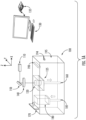
FIG. 1A is a schematic view a powder bed fusion (PBF) process used to manufacture a filter housing and filter, according to an embodiment of the present disclosure; -
FIG. 1B is a block diagram view of a controller utilized inFIG. 1A , according to an embodiment of the present disclosure; -
FIG. 2 is a perspective view of a monolithic filter housing and filter manufactured using a PBF process, according to an embodiment of the present disclosure; -
FIG. 3 is a cutaway view of the monolithic filter housing and filter ofFIG. 2 , according to an embodiment of the present disclosure; -
FIG. 4 is a perspective cutaway view of the monolithic filter housing and filter ofFIG. 2 , according to an embodiment of the present disclosure; -
FIG. 5 is an enlarged perspective cutaway view of the monolithic filter housing and filter ofFIG. 4 , according to an embodiment of the present disclosure; -
FIG. 6 is a schematic illustration view of a filter with passageways for use in the monolithic filter housing ofFIGS. 3-5 , according to an embodiment of the present disclosure; -
FIG. 7 is a schematic illustration view of the passageways ofFIGS. 6 , according to an embodiment of the present disclosure; -
FIG. 8 is a schematic illustration view of a filter with a corkscrew passageway for use in the monolithic filter housing ofFIGS. 3-5 , according to an embodiment of the present disclosure; and -
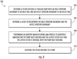
FIG. 9 is a flowchart illustrating a method of fabricating the monolithic filter housing and filter ofFIGS. 2-8 , according to an embodiment of the present disclosure. - A detailed description of one or more embodiments of the disclosed apparatus and method are presented herein by way of exemplification and not limitation with reference to the Figures.
- Fluid systems with pumps use filters so that contaminants are captured and not passed to the pump and then pumped downstream from the pump. The utilization of filters may minimize a reduction in performance and damage to downstream parts. The filter is typically an item that is insertable into a filter housing. There are various drawbacks to having the filter as a separate item from the filter housing. Thus, according to embodiments, the filter and filter housing are formed as a monolithic part, e.g., utilizing additive manufacturing (AM), and specifically Powder bed fusion (PBF). Using AM and software computer aided design (CAD) technologies, it may be feasible to design and fabricate a filter housing and filter as a monolithic structure utilizing powder bed fusion AM techniques. For example, the AM process may enable more flexibility in the design of the monolithic structure.
- Referring now to
FIG. 1A , asystem 100 for performing PBF is illustrated, in accordance with an embodiment of the present disclosure. Thesystem 100 uses a high-energy power laser (laser) 110 to selectively melt or sinter a metallic powder that is located in thepowder bed 120. The processes utilize aplatform 125 to hold the powder and build upon. In a laser powder bed process, thelaser 110 is operationally connected via wired or wireless networks to acomputer 130 with an associatedcontroller 135. The laser beam from thelaser 110 is reflected by amirror 150, then passes through a system oflenses 140 and onto theplatform 125. Themirror 150 is used to control the laser beam spot movement on the planar (x and y) directions on designed paths. After a layer of powder is selectively melted, theplatform 125 moves downward via action of abuild piston 160, arecoating blade 170 or brush pushes another layer of fresh powder from apowder dispenser tank 180, which may be moved via apowder supply piston 185, to a top of the previously built surface, and the laser scanning process is repeated. According to an embodiment, aluminum may be the material utilized as the powder. Other materials may also be utilized depending on pressures, temperature and working fluids, e.g., steel, titanium, etc. Anoverflow container 190 may be provided to recover redundant powder once a layer has been spread. One ormore sensors 194 may be provided by which thecomputer 130 monitors progress of the PBF process. Thebuild chamber 195 of thesystem 100 is filled with an inert gas, such as argon, to avoid oxidization of the metal as it melts and resolidifies. - Referring now to
FIG. 1B , with continued reference toFIG. 1A , thecontroller 135 for thesystem 100 is illustrated, in accordance with an embodiment of the present disclosure. As shown inFIG. 1B , thecontroller 135 identified herein may further include, in addition to a processor and non-volatile memory, one or more input and/or output (I/O) device interface(s) that are communicatively coupled via an onboard (local) interface to communicate among other devices. The onboard interface may include, for example but not limited to, an onboard system bus, including a control bus (for inter-device communications), an address bus (for physical addressing) and a data bus (for transferring data). That is, the system bus may enable the electronic communications between the processor, memory and I/O connections. The I/O connections may also include wired connections and/or wireless connections identified herein. The onboard interface may have additional elements, which are omitted for simplicity, such as controllers, buffers (caches), drivers, repeaters, and receivers to enable electronic communications. The memory may execute programs, access data, or lookup charts, or a combination of each, in furtherance of its processing, all of which may be stored in advance or received during execution of its processes by other computing devices, e.g., via a cloud service or other network connection with other processors. Embodiments can be in the form of processor-implemented processes and devices for practicing those processes, such as processor. Embodiments can also be in the form of computer code based modules, e.g., computer program code (e.g., computer program product) containing instructions embodied in tangible media (e.g., non-transitory computer readable medium), such as floppy diskettes, CD ROMs, hard drives, on processor registers as firmware, or any other non-transitory computer readable medium, wherein, when the computer program code is loaded into and executed by a computer, the computer becomes a device for practicing the embodiments. Embodiments can also be in the form of computer program code, for example, whether stored in a storage medium, loaded into and/or executed by a computer, or transmitted over some transmission medium, such as over electrical wiring or cabling, through fiber optics, or via electromagnetic radiation, wherein, when the computer program code is loaded into and executed by a computer, the computer becomes a device for practicing the exemplary embodiments. When implemented on a general-purpose microprocessor, the computer program code segments configure the microprocessor to create specific logic circuits. - Referring now to
FIGS. 2, 3, 4, and 5 , afilter assembly 200 is illustrated, in accordance with an embodiment of the present disclosure. Thefilter assembly 200 is composed of afilter housing 220 and alattice filter 270. Thefilter housing 220 may also be known as an inlet housing. - The
filter assembly 200 is manufactured to be monolithic. In other words, thefilter housing 220 and thelattice filter 270 are manufactured together to be monolithic such that thefilter assembly 200 is formed as a single piece comprising a unitary structure. In an embodiment, thefilter assembly 200 has no joints or seams. Thefilter assembly 200 may be manufactured or formed via an additive manufacturing technique known to one of skill in the art. In an embodiment, thefilter assembly 200 may be manufactured by growing the structure one layer at a time. In an embodiment, thefilter assembly 200 may be manufactured by powder bed fusion additive manufacturing. - In an alternative embodiment, the
lattice filter 270 may be manufactured via additive manufacturing separately from thefilter housing 200 and then inserted into thefilter housing 200. - The
filter housing 220 has a tubular shape. Thefilter housing 220 has aninlet end 240 and anoutlet end 260, located opposite theinlet end 240, which leads to thepump 210. Thefilter housing 220 is defined to include aninlet aperture boundary 230 at theinlet end 240 and anoutlet aperture boundary 250 at theoutlet end 260. Thelattice filter 270 is defined to be within eachfilter housing 220 between theinlet end 240 and theoutlet end 260. The configuration of thefilter housing 220 is defined on a computer readable medium, such as disclosed below, which will be utilized by the computer 130 (FIGS. 1A and1B ) to manufacture thefilter housing 220 and thefilter 270 via PBF using, e.g., thesystem 100 shown inFIGS. 1A and1B . - The
filter assembly 200 may be manufactured by performing an AM process to additively manufacture thefilter housing 220 and thelattice filter 270 as integral (e.g., monolithic, unitary) structures. - The
filter housing 220 includes ahousing bottom surface 280 at theoutlet end 260. Thehousing bottom surface 280 defines theoutlet aperture boundary 250 that forms anoutlet aperture 290. - The
filter housing 220 further includes ahousing exterior wall 300 that extends upwardly from thehousing bottom surface 280 to ahousing top surface 310 at theinlet end 240. Thehousing exterior wall 300 defines aninner surface 320 to form atubular cavity 330 between the housingtop surface 310 and the housing bottom surfaces 280. Further, theinlet aperture boundary 230, that forms aninlet aperture 340, is defined through thehousing exterior wall 300 or thehousing top surface 310. - The
lattice filter 270 may be have a tubular shape. More specifically, alattice filter body 350 may extend upwardly from afilter outlet end 360, which may be located at or adjacent theoutlet end 260, to afilter inlet end 370 that is at or adjacent theinlet end 240. Afilter cap 375 may or may not be present, at thefilter inlet end 370, may be configured as a solid surface. A latticed cap would allow fluid to entire thelattice filter 270 via the sides of thelattice filter 270 and not the top. - A mounting
flange 380 is defined along anouter surface 390 of thehousing exterior wall 300. The mountingflange 380 is configured to mount thefilter assembly 200 to apump 210. Aninlet conduit 400 may be integrally formed via the AM process with theinlet aperture boundary 230. Theinlet conduit 400 may include a conduitfirst end 405 that is integrally formed via the AM process with theinlet aperture boundary 230. Aconduit body 410 may extend away from the conduitfirst end 405 to a conduitsecond end 420. - The
filter housing 220 may be formed with abase disk 430 at theoutlet end 260. Thebase disk 430 defines theoutlet aperture boundary 250 having an outlet perimeter that is smaller than a housing wall perimeter defined by theinner surface 320 of thehousing exterior wall 300. Thelattice filter 270 may be integrally formed via the AM process with thebase disk 430. - An outer perimeter of the
lattice filter 270 may be smaller than the housing wall perimeter. Thefilter cap 375 of thelattice filter 270 may be spaced apart from theinlet end 240. Fluid may follow the flow arrows 500 through thelattice filter 270. - As shown in
FIGS. 2-5 , the tubular shape of thefilter housing 220 and the tubular shape of thelattice filter 270 may both be cylindrical. However, other shapes are within the scope of the embodiments. - As indicated, the
lattice filter 270 may be designed to provide structural support to thefilter housing 220, reducing the required structural characteristics of the filter housing itself. That is, the structural integrity of thefilter housing 220 may be at least partially provided by thelattice filter 270 rather than being entirely provided from the design of the housing structure itself. - Thus, the disclosed embodiments reduce a complex assembly process to a process of growing a monolithic structure. Benefits of the disclosed embodiments include: 1) reducing part count and simplifying an overall assembly process because the filter is part of the filter housing; 2) providing for many different types of configurations, e.g., the filter housing may have a greater sweep than machining may allow, and the shape, size and design of the filter may be varied and optimized for flow and pressure drop; and 3) utilizing the filter can as a structural support to the housing, being that the filter is integral to the housing, while still functioning as a filter.
- Referring now to
FIGS. 6 and 7 , within continued reference toFIGS. 1A ,1B , and2-5 , alattice filter 270 is illustrated, in accordance with an embodiment of the present disclosure.FIG. 7 illustrates thewhole lattice filter 270 withpassageways 600 within thelattice filter body 350 whileFIG. 6 illustrates only thepassageways 600 through thelattice filter 270 with the remaining portions of thelattice filter 270 removed. - As aforementioned, the
lattice filter 270 includes afilter inlet end 370 and afilter outlet end 360, located opposite thefilter inlet end 370, that fluidly couples to thepump 210. A central longitudinal axis A extends down a center of thelattice filter body 350 from thefilter inlet end 370 to thefilter outlet end 360. - As illustrated in
FIGS. 6 and 7 , thelattice filter 270 includes one ormore passageways 600 formed within thelattice filter body 350 of thelattice filter 270. Thepassageways 600 may be tubular in shape, as illustrated inFIG. 7 . The remaining portion of thelattice filter body 350 that is not apassageway 600 has a lattice structure, while thepassageway 600 is devoid of the lattice structure of thelattice filter body 350. In other words, thepassageway 600 does not contain a lattice structure and may be an open void. In another embodiment, if thepassageway 600 may also contain a lattice structure to act as a filter. This configured may work well if thepassageway 600 is larger. - The
passageways 600 extend from apassageway inlet 620 located at thefilter inlet end 370 to apassageway outlet 630 located at thefilter outlet end 360. Thepassageways 600 curve, swirl, or spiral between thepassageway inlet 620 and thepassageway outlet 630. In an embodiment, thepassageways 600 curve, swirl, or spiral around the central longitudinal axis A between thepassageway inlet 620 and thepassageway outlet 630. - The
walls 610 of thepassageway 600 that form thepassageways 600 may have the lattice structure fromlattice filter body 350 to allow particulate to escape as the fluid that flows through thepassageways 600 is swirled around the central longitudinal axis A. Alternatively, the passageway walls may have a solid structure and are not a lattice. - Advantageously, the spiral shape of the
passageways 600 creates a predetermined swirl direction for the fluid flow, which minimizes the work (energy/electricity) needed for the motor of thepump 210 to spin its impeller in that direction as the flow already wants to spin in that direction. - Referring now to
FIG. 8 , within continued reference toFIGS. 1A ,1B , and2-7 , alattice filter 270 is illustrated, in accordance with an embodiment of the present disclosure.FIG. 8 illustrates thewhole lattice filter 270 with acorkscrew passageway 800 formed within thelattice filter body 350. - As aforementioned, the
lattice filter 270 includes afilter inlet end 370 and a filter outlet end 360 located opposite thefilter inlet end 370. The central longitudinal axis A extends down a center of thelattice filter 270 from thefilter inlet end 370 to thefilter outlet end 360. - As illustrated in
FIG. 8 , thelattice filter 270 includes acorkscrew passageway 800 formed within thelattice filter body 350 of thelattice filter 270. Thecorkscrew passageway 800 extends between the central longitudinal axis A and a radiallyouter wall 296 of thelattice filter 270 as thecorkscrew passageway 800 corkscrews around the central longitudinal axis A between thefilter inlet end 370 and thefilter outlet end 360. Thecorkscrew passageway 800 is formed by and/or bounded on a top and a bottom side by acorkscrew wall 810 that spirals around the central longitudinal axis A between thefilter inlet end 370 and thefilter outlet end 360. Thecorkscrew wall 810 may be a solid structure or non-lattice structure that weaves or spirals its way through the lattice structure of thefilter body 350. Thecorkscrew passageway 800 itself may have the lattice structure of thefilter body 350. Thecorkscrew wall 810 of thepassageway 800 that form thecorkscrew passageway 800 may have one ormore orifices 840 to allow fluid to flow through theorifices 840 rather than following thecorkscrew passageway 800 and swirl around the central longitudinal axis A. Alternatively, thecorkscrew wall 810 may be solid with noorifices 840 or holes. - If the
corkscrew wall 810 is solid wall, then pressure drop in the system increases and the pump may have to work harder to flow fluid through the system. Advantageously, theorifices 840 help to reduce that pressure drop. Also advantageously, the corkscrew shape of thecorkscrew passageway 800 creates a predetermined swirl direction for the fluid flow, which minimizes the work (energy/electricity) needed for the motor of thepump 210 to spin its impeller in that direction as the flow already wants to spin in that direction. - The
corkscrew passageway 800 extend from apassageway inlet 820 located at thefilter inlet end 370 to apassageway outlet 830 located at thefilter outlet end 360. Thepassageway 800 curves, swirls, or spirals between thepassageway inlet 820 and thepassageway outlet 830. In an embodiment, thepassageway 800 curves, swirls, or spirals around the central longitudinal axis A between thepassageway inlet 820 and thepassageway outlet 830. - Referring now to
FIG. 9 , with continued reference toFIGS 1-4 , a flow chart of amethod 900 of manufacturing afilter housing 220 andlattice filter 270 for afilter assembly 200 is illustrated, in accordance with an embodiment of the disclosure. Thefilter housing 220 andlattice filter 270 are monolithic. - At
block 904, afilter housing 220 is defined as a tubular shape with aninlet aperture boundary 230 at aninlet end 240, and anoutlet aperture boundary 250 at anoutlet end 260. - At
block 906, alattice filter 270 is defined between theinlet aperture boundary 230 and theoutlet aperture boundary 250. - At
block 908, an AM process is performed to additively manufacture thefilter housing 220 and thelattice filter 270 such that thelattice filter 270 is integral with thefilter housing 220. - The
lattice filter 270 includes alattice filter body 350 extending from afilter inlet end 370 to afilter outlet end 360. Thelattice filter 270 having a lattice structure. Thelattice filter 270 also includes one ormore passageways lattice filter body 350. Each of the one ormore passageways passageway inlet filter inlet end 370 and apassageway outlet filer outlet end 360. Each of the one ormore passageways passageway inlet passageway outlet more passageways passageway inlet passageway outlet - At
block 910, thefilter housing 220 is coupled to apump 210. - The
method 900 may further include that the AM process comprises applying laser bed powder fusion. - Technical effects and benefits of the features described herein include forming spiral passageways within a filter for a pump using additive manufacturing.
- The term "about" is intended to include the degree of error associated with measurement of the particular quantity based upon the equipment available at the time of filing the application.
- The terminology used herein is for the purpose of describing particular embodiments only and is not intended to be limiting of the present disclosure. As used herein, the singular forms "a", "an" and "the" are intended to include the plural forms as well, unless the context clearly indicates otherwise. It will be further understood that the terms "comprises" and/or "comprising," when used in this specification, specify the presence of stated features, integers, steps, operations, elements, and/or components, but do not preclude the presence or addition of one or more other features, integers, steps, operations, element components, and/or groups thereof.
- While the present disclosure has been described with reference to an exemplary embodiment or embodiments, it will be understood by those skilled in the art that various changes may be made without departing from the scope of the invention as defined by the claims. In addition, many modifications may be made to adapt a particular situation or material to the teachings of the present disclosure without departing from the scope of the claims. Therefore, it is intended that the present disclosure not be limited to the particular embodiment disclosed as the best mode contemplated for carrying out this present disclosure, but that the present disclosure will include all embodiments falling within the scope of the claims.
Claims (13)
- A lattice filter for use in an inlet housing of a pump assembly, the lattice filter comprising:a lattice filter body (350) extending from a filter inlet (370) end to a filter outlet end (360), the lattice filter having a lattice structure; andone or more passageways (600) within the lattice filter body,wherein each of the one or more passageways includes a passageway inlet (620) located at the filter inlet end and a passageway outlet (630) located at the filter outlet end, andwherein each of the one or more passageways extend from the passageway inlet to the passageway outlet.
- The lattice filter of claim 1, wherein each of the one or more passageways curve, swirl, or spiral between the passageway inlet and the passageway outlet.
- The lattice filter of claim 1, wherein each of the one or more passageways curve, swirl, or spiral around a central longitudinal axis of the lattice filter body between the passageway inlet and the passageway outlet, the central longitudinal axis extends down a center of the lattice filter body from the filter inlet end to the filter outlet end.
- The lattice filter of claim 1, 2 or 3, wherein each of the one or more passageways is devoid of the lattice structure of the lattice filter body or contains the lattice structure.
- The lattice filter of claim 1, wherein each of the one or more passageways are a corkscrew passageway formed by a corkscrew wall that spirals around a central longitudinal axis A of the lattice filter body between the passageway inlet and the passageway outlet, the central longitudinal axis extends down a center of the lattice filter body from the filter inlet end to the filter outlet end.
- The lattice filter of claim 5, wherein the corkscrew passageway has the lattice structure of the filter body.
- The lattice filter of claim 5, wherein the corkscrew wall includes one or more orifices.
- The lattice filter of claim 5, wherein the corkscrew wall is solid.
- A filter assembly, wherein the filter assembly is monolithic and comprises:a filter housing having a tubular shape with an inlet aperture boundary at an inlet end and an outlet aperture boundary at an outlet end;a lattice filter as claimed in any preceding claim that is integrally formed with the filter housing via an additive manufacturing, AM, process, the lattice filter being located between the inlet aperture boundary and the outlet aperture boundary.
- A method of manufacturing a filter housing and lattice filter for a filter assembly, wherein the filter housing and lattice filter are monolithic, the method comprising:defining a filter housing (220) as a tubular shape with an inlet aperture boundary (230) at an inlet end (240), and an outlet aperture boundary (250) at an outlet end (260);defining a lattice filter (270) between the inlet aperture boundary and the outlet aperture boundary; andperforming an additive manufacturing, AM, process to additively manufacture the filter housing and the lattice filter such that the lattice filter is integral with the filter housing,the lattice filter comprising:a lattice filter body (350) extending from a filter inlet end (370) to a filter outlet end (360), the lattice filter having a lattice structure; andone or more passageways (600) within the lattice filter body,wherein each of the one or more passageways includes a passageway inlet (620) located at the filter inlet end and a passageway outlet (630) located at the filter outlet end, andwherein each of the one or more passageways extend from the passageway inlet to the passageway outlet.
- The method of claim 10, further comprising:
coupling the filter housing to a pump. - The method of claim 10 or 11, wherein the AM process comprises applying laser bed powder fusion.
- The method of claim 10, 11 or 12, wherein each of the one or more passageways curve, swirl, or spiral between the passageway inlet and the passageway outlet.
Applications Claiming Priority (1)
| Application Number | Priority Date | Filing Date | Title |
|---|---|---|---|
| US17/545,103 US12290774B2 (en) | 2021-12-08 | 2021-12-08 | Pump filter with predetermined swirl |
Publications (1)
| Publication Number | Publication Date |
|---|---|
| EP4194701A1 true EP4194701A1 (en) | 2023-06-14 |
Family
ID=84389392
Family Applications (1)
| Application Number | Title | Priority Date | Filing Date |
|---|---|---|---|
| EP22211440.7A Pending EP4194701A1 (en) | 2021-12-08 | 2022-12-05 | Pump filter with predetermined swirl |
Country Status (2)
| Country | Link |
|---|---|
| US (1) | US12290774B2 (en) |
| EP (1) | EP4194701A1 (en) |
Citations (6)
| Publication number | Priority date | Publication date | Assignee | Title |
|---|---|---|---|---|
| US5511585A (en) * | 1994-03-31 | 1996-04-30 | The Lee Company | Method and device for providing fluid resistance within a flow passageway |
| WO1996028241A1 (en) * | 1995-03-10 | 1996-09-19 | Isis Innovation Limited | Filter comprising one or more ducts |
| US20180147534A1 (en) * | 2015-05-29 | 2018-05-31 | Technologies Avancees Et Membranes Industrielles | Single-piece column structure for the separation of a fluid medium |
| US20180283794A1 (en) * | 2017-03-28 | 2018-10-04 | General Electric Company | Tubular Array Heat Exchanger |
| EP3594550A1 (en) * | 2018-07-10 | 2020-01-15 | Hamilton Sundstrand Corporation | Heated pipe for liquid flows |
| DE102018119730A1 (en) * | 2018-08-14 | 2020-02-20 | Danfoss Power Solutions Gmbh & Co. Ohg | Improved fluid lines |
Family Cites Families (6)
| Publication number | Priority date | Publication date | Assignee | Title |
|---|---|---|---|---|
| US2985306A (en) * | 1959-09-30 | 1961-05-23 | Bendix Corp | Fluid filter |
| GB2088958B (en) | 1980-12-05 | 1983-11-23 | Plessey Co Ltd | A rotary pump for a liquid containing solid contaminants |
| US7572311B2 (en) * | 2002-10-28 | 2009-08-11 | Geo2 Technologies, Inc. | Highly porous mullite particulate filter substrate |
| WO2016204484A1 (en) | 2015-06-15 | 2016-12-22 | 아이닉스(주) | Automatic washing device for filter of motor pump |
| US9987508B2 (en) * | 2016-08-31 | 2018-06-05 | Emerson Process Management Regulator Technologies Tulsa, Llc | Hybrid composite flame cell |
| US11779869B2 (en) * | 2021-10-20 | 2023-10-10 | Irpi Llc | Multiplex inertial filter, collector and separator |
-
2021
- 2021-12-08 US US17/545,103 patent/US12290774B2/en active Active
-
2022
- 2022-12-05 EP EP22211440.7A patent/EP4194701A1/en active Pending
Patent Citations (6)
| Publication number | Priority date | Publication date | Assignee | Title |
|---|---|---|---|---|
| US5511585A (en) * | 1994-03-31 | 1996-04-30 | The Lee Company | Method and device for providing fluid resistance within a flow passageway |
| WO1996028241A1 (en) * | 1995-03-10 | 1996-09-19 | Isis Innovation Limited | Filter comprising one or more ducts |
| US20180147534A1 (en) * | 2015-05-29 | 2018-05-31 | Technologies Avancees Et Membranes Industrielles | Single-piece column structure for the separation of a fluid medium |
| US20180283794A1 (en) * | 2017-03-28 | 2018-10-04 | General Electric Company | Tubular Array Heat Exchanger |
| EP3594550A1 (en) * | 2018-07-10 | 2020-01-15 | Hamilton Sundstrand Corporation | Heated pipe for liquid flows |
| DE102018119730A1 (en) * | 2018-08-14 | 2020-02-20 | Danfoss Power Solutions Gmbh & Co. Ohg | Improved fluid lines |
Also Published As
| Publication number | Publication date |
|---|---|
| US20230173420A1 (en) | 2023-06-08 |
| US12290774B2 (en) | 2025-05-06 |
Similar Documents
| Publication | Publication Date | Title |
|---|---|---|
| CN109070217B (en) | An additive machine that builds surfaces using rotation | |
| CN109900152B (en) | Support form for heat exchanger tubes and method for producing heat exchanger tubes | |
| US12162068B2 (en) | Removing filling material from a cavity in a component and apparatus for performing same | |
| CN114730172B (en) | Computer-aided design method, computer-aided design system, and computer-readable medium for hybrid additive and subtractive manufacturing | |
| JP2018111097A (en) | Ceramic filter | |
| EP3455527B1 (en) | Late customization on valve body end connections using additive manufacturing | |
| US9597732B2 (en) | Flow restrictor assemblies including a monolithic flow restrictor and methods for manufacturing the same | |
| EP4198320A1 (en) | Additively manufactured ejector pump | |
| US20120104172A1 (en) | Fuel Line in an Aircraft | |
| EP3655636B1 (en) | Acoustic attenuator for a turbomachine and methodology for additively manufacturing said acoustic attenuator | |
| US12290774B2 (en) | Pump filter with predetermined swirl | |
| RU2756763C2 (en) | Algorithm for predicting welding deformation resulting from connecting flanges to the end face of valve body casting by butt welding or socket welding | |
| CN111093864B (en) | Capsule for hot isostatic pressing | |
| JP2018519181A (en) | Flow restriction device | |
| JP2020509934A (en) | System and method for additive manufacturing of boiler tubes | |
| CN113953758B (en) | Control method, device and system of in-situ material-increasing repairing equipment and repairing method | |
| EP4086464A1 (en) | Monolithic additively manufactured pump inlet housing and filter | |
| US20180361473A1 (en) | System and method for additively manufacturing an object | |
| KR102342464B1 (en) | Turbomachine alignment key and related turbomachine | |
| US20180018000A1 (en) | Integrated liquid cooling of a server system | |
| US20200078866A1 (en) | Method for manufacturing metal member | |
| CN105772297A (en) | Heavy type part spraying device | |
| CA3024267C (en) | Late customization on valve body end connections using additive manufacturing | |
| US11872627B2 (en) | Method and apparatus for fluid flow for additive manufacturing apparatus | |
| CN103998341B (en) | For discharging/accommodate the device of liquid for spacecraft storage tank |
Legal Events
| Date | Code | Title | Description |
|---|---|---|---|
| PUAI | Public reference made under article 153(3) epc to a published international application that has entered the european phase |
Free format text: ORIGINAL CODE: 0009012 |
|
| STAA | Information on the status of an ep patent application or granted ep patent |
Free format text: STATUS: THE APPLICATION HAS BEEN PUBLISHED |
|
| AK | Designated contracting states |
Kind code of ref document: A1 Designated state(s): AL AT BE BG CH CY CZ DE DK EE ES FI FR GB GR HR HU IE IS IT LI LT LU LV MC ME MK MT NL NO PL PT RO RS SE SI SK SM TR |
|
| STAA | Information on the status of an ep patent application or granted ep patent |
Free format text: STATUS: REQUEST FOR EXAMINATION WAS MADE |
|
| 17P | Request for examination filed |
Effective date: 20231214 |
|
| RBV | Designated contracting states (corrected) |
Designated state(s): AL AT BE BG CH CY CZ DE DK EE ES FI FR GB GR HR HU IE IS IT LI LT LU LV MC ME MK MT NL NO PL PT RO RS SE SI SK SM TR |
|
| STAA | Information on the status of an ep patent application or granted ep patent |
Free format text: STATUS: EXAMINATION IS IN PROGRESS |
|
| 17Q | First examination report despatched |
Effective date: 20250807 |