EP3594550A1 - Heated pipe for liquid flows - Google Patents
Heated pipe for liquid flows Download PDFInfo
- Publication number
- EP3594550A1 EP3594550A1 EP19185509.7A EP19185509A EP3594550A1 EP 3594550 A1 EP3594550 A1 EP 3594550A1 EP 19185509 A EP19185509 A EP 19185509A EP 3594550 A1 EP3594550 A1 EP 3594550A1
- Authority
- EP
- European Patent Office
- Prior art keywords
- wall
- screen
- pipe assembly
- pipe
- fuel
- Prior art date
- Legal status (The legal status is an assumption and is not a legal conclusion. Google has not performed a legal analysis and makes no representation as to the accuracy of the status listed.)
- Granted
Links
- 239000007788 liquid Substances 0.000 title 1
- 239000000446 fuel Substances 0.000 claims abstract description 85
- 239000000155 melt Substances 0.000 claims abstract description 9
- 238000010438 heat treatment Methods 0.000 claims description 72
- 239000012530 fluid Substances 0.000 claims description 67
- 238000011144 upstream manufacturing Methods 0.000 claims description 57
- 229910003460 diamond Inorganic materials 0.000 claims description 4
- 239000010432 diamond Substances 0.000 claims description 4
- 238000002844 melting Methods 0.000 claims description 4
- 230000008018 melting Effects 0.000 claims description 4
- 238000000034 method Methods 0.000 claims description 4
- 230000000903 blocking effect Effects 0.000 claims description 3
- 230000001419 dependent effect Effects 0.000 claims 2
- 239000002245 particle Substances 0.000 description 52
- XLYOFNOQVPJJNP-UHFFFAOYSA-N water Substances O XLYOFNOQVPJJNP-UHFFFAOYSA-N 0.000 description 5
- 239000002828 fuel tank Substances 0.000 description 2
- 239000000463 material Substances 0.000 description 2
- 229910052751 metal Inorganic materials 0.000 description 2
- 239000002184 metal Substances 0.000 description 2
- RTAQQCXQSZGOHL-UHFFFAOYSA-N Titanium Chemical compound [Ti] RTAQQCXQSZGOHL-UHFFFAOYSA-N 0.000 description 1
- 229910052782 aluminium Inorganic materials 0.000 description 1
- XAGFODPZIPBFFR-UHFFFAOYSA-N aluminium Chemical compound [Al] XAGFODPZIPBFFR-UHFFFAOYSA-N 0.000 description 1
- 229910001026 inconel Inorganic materials 0.000 description 1
- 239000000203 mixture Substances 0.000 description 1
- 238000012986 modification Methods 0.000 description 1
- 230000004048 modification Effects 0.000 description 1
- 229910001220 stainless steel Inorganic materials 0.000 description 1
- 239000010935 stainless steel Substances 0.000 description 1
- 239000010936 titanium Substances 0.000 description 1
- 229910052719 titanium Inorganic materials 0.000 description 1
Images


Classifications
-
- B—PERFORMING OPERATIONS; TRANSPORTING
- B64—AIRCRAFT; AVIATION; COSMONAUTICS
- B64D—EQUIPMENT FOR FITTING IN OR TO AIRCRAFT; FLIGHT SUITS; PARACHUTES; ARRANGEMENTS OR MOUNTING OF POWER PLANTS OR PROPULSION TRANSMISSIONS IN AIRCRAFT
- B64D37/00—Arrangements in connection with fuel supply for power plant
- B64D37/32—Safety measures not otherwise provided for, e.g. preventing explosive conditions
-
- B—PERFORMING OPERATIONS; TRANSPORTING
- B64—AIRCRAFT; AVIATION; COSMONAUTICS
- B64D—EQUIPMENT FOR FITTING IN OR TO AIRCRAFT; FLIGHT SUITS; PARACHUTES; ARRANGEMENTS OR MOUNTING OF POWER PLANTS OR PROPULSION TRANSMISSIONS IN AIRCRAFT
- B64D37/00—Arrangements in connection with fuel supply for power plant
- B64D37/34—Conditioning fuel, e.g. heating
-
- F—MECHANICAL ENGINEERING; LIGHTING; HEATING; WEAPONS; BLASTING
- F02—COMBUSTION ENGINES; HOT-GAS OR COMBUSTION-PRODUCT ENGINE PLANTS
- F02M—SUPPLYING COMBUSTION ENGINES IN GENERAL WITH COMBUSTIBLE MIXTURES OR CONSTITUENTS THEREOF
- F02M31/00—Apparatus for thermally treating combustion-air, fuel, or fuel-air mixture
- F02M31/02—Apparatus for thermally treating combustion-air, fuel, or fuel-air mixture for heating
- F02M31/12—Apparatus for thermally treating combustion-air, fuel, or fuel-air mixture for heating electrically
- F02M31/125—Fuel
-
- F—MECHANICAL ENGINEERING; LIGHTING; HEATING; WEAPONS; BLASTING
- F16—ENGINEERING ELEMENTS AND UNITS; GENERAL MEASURES FOR PRODUCING AND MAINTAINING EFFECTIVE FUNCTIONING OF MACHINES OR INSTALLATIONS; THERMAL INSULATION IN GENERAL
- F16L—PIPES; JOINTS OR FITTINGS FOR PIPES; SUPPORTS FOR PIPES, CABLES OR PROTECTIVE TUBING; MEANS FOR THERMAL INSULATION IN GENERAL
- F16L53/00—Heating of pipes or pipe systems; Cooling of pipes or pipe systems
- F16L53/30—Heating of pipes or pipe systems
- F16L53/32—Heating of pipes or pipe systems using hot fluids
-
- F—MECHANICAL ENGINEERING; LIGHTING; HEATING; WEAPONS; BLASTING
- F16—ENGINEERING ELEMENTS AND UNITS; GENERAL MEASURES FOR PRODUCING AND MAINTAINING EFFECTIVE FUNCTIONING OF MACHINES OR INSTALLATIONS; THERMAL INSULATION IN GENERAL
- F16L—PIPES; JOINTS OR FITTINGS FOR PIPES; SUPPORTS FOR PIPES, CABLES OR PROTECTIVE TUBING; MEANS FOR THERMAL INSULATION IN GENERAL
- F16L55/00—Devices or appurtenances for use in, or in connection with, pipes or pipe systems
- F16L55/02—Energy absorbers; Noise absorbers
- F16L55/027—Throttle passages
- F16L55/02709—Throttle passages in the form of perforated plates
- F16L55/02718—Throttle passages in the form of perforated plates placed transversely
-
- F—MECHANICAL ENGINEERING; LIGHTING; HEATING; WEAPONS; BLASTING
- F16—ENGINEERING ELEMENTS AND UNITS; GENERAL MEASURES FOR PRODUCING AND MAINTAINING EFFECTIVE FUNCTIONING OF MACHINES OR INSTALLATIONS; THERMAL INSULATION IN GENERAL
- F16L—PIPES; JOINTS OR FITTINGS FOR PIPES; SUPPORTS FOR PIPES, CABLES OR PROTECTIVE TUBING; MEANS FOR THERMAL INSULATION IN GENERAL
- F16L55/00—Devices or appurtenances for use in, or in connection with, pipes or pipe systems
- F16L55/24—Preventing accumulation of dirt or other matter in the pipes, e.g. by traps, by strainers
-
- F—MECHANICAL ENGINEERING; LIGHTING; HEATING; WEAPONS; BLASTING
- F28—HEAT EXCHANGE IN GENERAL
- F28D—HEAT-EXCHANGE APPARATUS, NOT PROVIDED FOR IN ANOTHER SUBCLASS, IN WHICH THE HEAT-EXCHANGE MEDIA DO NOT COME INTO DIRECT CONTACT
- F28D7/00—Heat-exchange apparatus having stationary tubular conduit assemblies for both heat-exchange media, the media being in contact with different sides of a conduit wall
- F28D7/10—Heat-exchange apparatus having stationary tubular conduit assemblies for both heat-exchange media, the media being in contact with different sides of a conduit wall the conduits being arranged one within the other, e.g. concentrically
- F28D7/106—Heat-exchange apparatus having stationary tubular conduit assemblies for both heat-exchange media, the media being in contact with different sides of a conduit wall the conduits being arranged one within the other, e.g. concentrically consisting of two coaxial conduits or modules of two coaxial conduits
-
- F—MECHANICAL ENGINEERING; LIGHTING; HEATING; WEAPONS; BLASTING
- F28—HEAT EXCHANGE IN GENERAL
- F28F—DETAILS OF HEAT-EXCHANGE AND HEAT-TRANSFER APPARATUS, OF GENERAL APPLICATION
- F28F1/00—Tubular elements; Assemblies of tubular elements
- F28F1/10—Tubular elements and assemblies thereof with means for increasing heat-transfer area, e.g. with fins, with projections, with recesses
- F28F1/12—Tubular elements and assemblies thereof with means for increasing heat-transfer area, e.g. with fins, with projections, with recesses the means being only outside the tubular element
- F28F1/34—Tubular elements and assemblies thereof with means for increasing heat-transfer area, e.g. with fins, with projections, with recesses the means being only outside the tubular element and extending obliquely
- F28F1/36—Tubular elements and assemblies thereof with means for increasing heat-transfer area, e.g. with fins, with projections, with recesses the means being only outside the tubular element and extending obliquely the means being helically wound fins or wire spirals
-
- B—PERFORMING OPERATIONS; TRANSPORTING
- B22—CASTING; POWDER METALLURGY
- B22F—WORKING METALLIC POWDER; MANUFACTURE OF ARTICLES FROM METALLIC POWDER; MAKING METALLIC POWDER; APPARATUS OR DEVICES SPECIALLY ADAPTED FOR METALLIC POWDER
- B22F5/00—Manufacture of workpieces or articles from metallic powder characterised by the special shape of the product
- B22F5/10—Manufacture of workpieces or articles from metallic powder characterised by the special shape of the product of articles with cavities or holes, not otherwise provided for in the preceding subgroups
-
- B—PERFORMING OPERATIONS; TRANSPORTING
- B33—ADDITIVE MANUFACTURING TECHNOLOGY
- B33Y—ADDITIVE MANUFACTURING, i.e. MANUFACTURING OF THREE-DIMENSIONAL [3-D] OBJECTS BY ADDITIVE DEPOSITION, ADDITIVE AGGLOMERATION OR ADDITIVE LAYERING, e.g. BY 3-D PRINTING, STEREOLITHOGRAPHY OR SELECTIVE LASER SINTERING
- B33Y80/00—Products made by additive manufacturing
-
- F—MECHANICAL ENGINEERING; LIGHTING; HEATING; WEAPONS; BLASTING
- F16—ENGINEERING ELEMENTS AND UNITS; GENERAL MEASURES FOR PRODUCING AND MAINTAINING EFFECTIVE FUNCTIONING OF MACHINES OR INSTALLATIONS; THERMAL INSULATION IN GENERAL
- F16L—PIPES; JOINTS OR FITTINGS FOR PIPES; SUPPORTS FOR PIPES, CABLES OR PROTECTIVE TUBING; MEANS FOR THERMAL INSULATION IN GENERAL
- F16L9/00—Rigid pipes
- F16L9/18—Double-walled pipes; Multi-channel pipes or pipe assemblies
-
- Y—GENERAL TAGGING OF NEW TECHNOLOGICAL DEVELOPMENTS; GENERAL TAGGING OF CROSS-SECTIONAL TECHNOLOGIES SPANNING OVER SEVERAL SECTIONS OF THE IPC; TECHNICAL SUBJECTS COVERED BY FORMER USPC CROSS-REFERENCE ART COLLECTIONS [XRACs] AND DIGESTS
- Y02—TECHNOLOGIES OR APPLICATIONS FOR MITIGATION OR ADAPTATION AGAINST CLIMATE CHANGE
- Y02T—CLIMATE CHANGE MITIGATION TECHNOLOGIES RELATED TO TRANSPORTATION
- Y02T10/00—Road transport of goods or passengers
- Y02T10/10—Internal combustion engine [ICE] based vehicles
- Y02T10/12—Improving ICE efficiencies
Definitions
- the present disclosure relates to deicing fuel flowing in a pipe.
- Ice particles can form in aircraft fuel tanks and front-end components of an engine fuel system. Such ice particles mix with fuel and travel downstream along with the fuel. Ice particles can damage downstream components. As a result, ice is usually melted via electrical heating elements located in the fuel lines. Use of electrical heating elements to melt ice particles flowing with the fuel can be inefficient.
- a pipe assembly includes a first wall having an inner surface defining a fuel flowpath, a second wall spaced radially outward of the first wall, a gap formed between the first wall and the second wall defining a flow passage, and a screen positioned within the fuel flowpath being shaped and configured to direct ice in the fuel flowpath toward the inner surface such that heat from the first wall melts the ice.
- a heated pipe assembly includes a pipe extending from an upstream end to a downstream end and including an annular first wall creating a fuel flowpath, an annular second wall radially spaced from the first wall, an annular gap formed between the first wall and the second wall, a heating fluid inlet that receives a heating fluid, the heating fluid inlet extending through the second wall and into the annular gap, a heating fluid outlet that discharges the heating fluid, the heating fluid outlet extending from the annular gap and through the second wall, and a helical rib extending between the first wall and the second wall and defining a flow passage in the annular gap.
- the flow passage provides a heating flowpath configured to contain the heating fluid to heat the first wall.
- the heated pipe assembly further includes a screen connected to the first wall of the pipe and extending across the fuel flowpath.
- the screen is shaped to direct ice in the fuel flowpath to the first wall and trap the ice against the first wall such that heat from the first wall melts the ice.
- a method of preventing ice from blocking a fuel flowpath includes urging ice flowing through the fuel flowpath radially outwardly toward an inner surface of a first wall that defines the fuel flowpath, flowing a fluid in a flow passage defined between the first wall and a second wall, increasing a temperature of the inner surface with the flowing of the fluid, and melting the ice.
- the present disclosure describes a heated screen in the fuel flowpath of a double-walled heated pipe.
- the screen blocks ice particles in the fuel flowpath and directs the ice particles to the first wall of the heated pipe, trapping the ice particles against the first wall until they melt and flow downstream as water.
- ice particles are prevented from clogging or damaging downstream components without requiring electrical heating.
- FIG. 1A is a cross-sectional perspective view of heated pipe assembly 10 showing pipe 12 and screen 14 having a conical shape.
- FIG. 1B is a cross-sectional view of heated pipe assembly 10 showing pipe 12 and screen 14, which has a conical shape.
- FIG. 1C is a cross-sectional end view of heated pipe assembly 10 showing pipe 12 and conical shaped screen 14.
- Heated pipe assembly 10 includes pipe 12 and screen 14.
- Pipe 12 includes upstream end 16, downstream end 18, first wall 20, fuel flowpath 22, second wall 24, annular gap 26, heating fluid inlet 28, heating fluid outlet 30, rib 32, and flow passage 34.
- Screen 14 includes conical portion 36 (which includes downstream end 38, upstream end 40, upstream side 42, downstream side 44, and hollow portion 46) holes 48, and support structure 50.
- Pipe 12 extends from upstream end 16 to downstream end 18.
- Pipe 12 has annular first, or inner, wall 20 extending from upstream end 16 to downstream end 18.
- First wall 20 has an inner surface that creates, or defines, fuel flowpath 22.
- Fuel flowpath 22 provides a flowpath for fuel F within pipe 12.
- Annular second, or outer, wall 24 is spaced radially outward of first wall 20 such that first wall 20 is within second wall 24. As such, first wall 20 and second wall 24 are concentric.
- Annular gap 26 is an annular space formed between first wall 20 and second wall 24.
- Heating fluid inlet 28 extends through second wall 24 and into annular gap 26.
- Heating fluid inlet 28 is an opening that receives heating fluid H into heated pipe assembly 10.
- Heating fluid H is a hot fluid, such as oil or fuel from a downstream heat exchanger.
- Heating fluid outlet 30 extends from annular gap 26 through second wall 24.
- Heating fluid outlet 30 is an opening that discharges heating fluid H from heated pipe assembly 10.
- Rib 32 extends between first wall 20 and second wall 24. In this embodiment, rib 32 is helical. In alternate embodiments, rib 32 may be any suitable shape. Rib 32 may be one continuous rib or multiple spaced apart ribs.
- Annular gap 26 and rib 32 define flow passage 34 within annular gap 26. Flow passage 34 provides a heating flowpath in annular gap 26 to contain heating fluid H.
- Screen 14 is connected to an inner surface of first wall 20 of pipe 12 and extends across fuel flowpath 22. As such, screen 14 is positioned within fuel flowpath 22.
- screen 14 has a conical, or bell, shape. In alternate embodiments, screen 14 may have any suitable shape.
- Screen 14 has conical portion 36 with circular downstream end 38 having a periphery connected to first wall 20 and upstream end 40 extending upstream into fuel flowpath 22. Upstream end 40 is not connected to first wall 20.
- Conical portion 36 is shaped like a cone or bell.
- Upstream side 42 is the upstream surface of conical portion 36.
- Downstream side 44 is the downstream surface of conical portion 36.
- Downstream side 44 defines hollow portion 46 within conical portion 36.
- Hollow portion 46 extends upstream from downstream end 38 of conical portion 36.
- conical portion 36 is hollow.
- Holes 48 extend from upstream side 42 to downstream side 44.
- holes 48 are diamond shaped.
- holes 48 may be circular, polygonal, or any other suitable shape.
- Support structure 50 is connected to conical portion 36.
- support structure 50 includes three legs spaced evenly around conical portion 36.
- support structure 50 may have two, four, or any other suitable number of legs to both maximize strength and minimize weight and cost of support structure 50.
- First ends of legs are connected to upstream side 42 near upstream end 40 of conical portion 36.
- Second ends of legs are connected to first wall 20.
- screen 14 may not include support structure 50.
- Heated pipe assembly 10, including pipe 12 and screen 14, may be additively manufactured.
- Heated pipe assembly 10 is positioned within a fuel system of an aircraft.
- heated pipe assembly 10 may be located just downstream of a boost pump and upstream of a main fuel pump.
- Fuel F moves axially through fuel flowpath 22 of pipe 12 from upstream end 16 to downstream end 18. Fuel F is cold at upstream end 16. Heating fluid H enters pipe 12 at heating fluid inlet 28 and moves, or flows, through flow passage 34 in annular gap 26 to exit pipe 12 at heating fluid outlet 30. Heating fluid H is warm at heating fluid inlet 28. Helical rib 32 causes heating fluid H to flow around first wall 20 in a helical pattern. As such, flow passage 34 provides a heating flowpath to heat first wall 20 and screen 14. Heating fluid H contacts an outer surface of first wall 20, transferring heat to first wall 20 and increasing the temperature of the inner surface of first wall 20. Consequently, heating fluid H loses heat as heating fluid H moves through flow passage 34. An inner surface of heated first wall 20 contacts screen 14, transferring heat to screen 14. Heated first wall 20 also contacts and transfers heat to fuel F as fuel F moves through fuel flowpath 22. As such, fuel F is warmer at downstream end 18 as fuel F exits pipe 12.
- Ice particles I may form in aircraft fuel tanks or front-end components of an engine fuel system. Such ice particles I may travel downstream through fuel flowpath 22 along with fuel F. As a result, fuel F may contain ice particles I at upstream end 16. As fuel F moves through fuel flowpath 22, screen 14 blocks ice particles I. Ice particles I contact screen 14 and begin to melt. Ice particles I not fully melted by heated screen 14 move downstream along screen 14. Screen 14 is shaped to direct, or urge, ice particles I in fuel flowpath 22 radially outwardly toward an inner diameter, or inner surface, of first wall 20 and trap ice particles I against the inner surface of first wall 20.
- ice particles I at upstream side 42 of a periphery of circular downstream end 38 of screen 14 are adjacent first wall 20, and heat from first wall 20 melts ice particles I. Heated screen 14 may also provide heat to melt ice particles I. As such, heated pipe assembly 10 acts as a heat exchanger between heating fluid H and fuel F with ice particles I.
- Holes 48 allow fuel F to bypass screen 14. Ice particles I smaller than holes 48 are also able to bypass screen 14. Ice particles I larger than holes 48 are prevented from moving past screen 14 to downstream end 18. Thus, holes 48 are sized and shaped based on the size of ice particles I that screen 14 is intended to block while also maintaining an appropriate pressure drop. Screen 14 is fine enough that screen 14 can capture the desired amount of ice particles I while being coarse enough not to cause a pressure drop across screen 14 high enough that fuel F stops flowing through fuel flowpath 22. Ice particles I are trapped against heated first wall 20 by heated screen 14 until ice particles I melt. Melted ice particles pass through screen 14 as water.
- Ice particles may damage downstream components or become problematic within downstream components, such as the fuel metering unit. As a result, ice is usually melted via electrical heating elements located in the fuel lines. For example, fuel heaters may be attached to the pipe, having a heater element positioned around the outside of the pipe to electrically heat the fuel. Electrical heating requires power. Additionally, ice particles can move through a heated pipe assembly without melting by the time the fuel exits the heated pipe assembly.
- Heated pipe assembly 10 provides an effective in-line method of deicing fuel without requiring electrical heating.
- Screen 14 also prevents large ice particles from exiting the heated pipe assembly along with fuel F.
- Screen 14 keeps ice particles I within heated pipe assembly 10 for a longer amount of time and directs ice particles I to an optimal heat source, heated first wall 20, to cause ice particles I to melt. Therefore, not only are ice particles I caught and trapped by screen 14 until ice particles I melt, heat is more greatly distributed to ice particles I such that ice particles I melt more quickly. As a result, ice particles I do not accumulate or cause blockage within heated pipe assembly 10. Ice particles I stay within fuel flowpath 22 long enough to melt before proceeding as water to the next part of the fuel system.
- heated pipe assembly 10 efficiently melts ice particles I, preventing ice particles I from moving downstream and clogging or damaging other components, without resorting to electrical means.
- FIG. 2 is a cross-sectional perspective view of heated pipe assembly 10A showing pipe 12A and screen 14A with crossbar 52.
- Heated pipe assembly 10A includes pipe 12A and screen 14A.
- Pipe 12A includes first wall 20A.
- Screen 14A includes conical portion 36A (which includes downstream end 38A, upstream end 40A, and downstream side 44A, and hollow portion 46A) and crossbar 52.
- Pipe 12A has the same structure and function as described in reference to pipe 12 in FIGS. 1A , 1B , and 1C .
- Screen 14A has the same structure and function as described in reference to screen 14 in FIGS. 1A , 1B , and 1C except that screen 14A also includes crossbar 52.
- Crossbar 52 is a rod or bar that extends across hollow portion 46A within conical portion 36A. As such, ends of crossbar 52 are attached to downstream side 44A of conical portion 36A. In this embodiment, crossbar 52 is near downstream end 38A of conical portion 36. In alternate embodiments, crossbar 52 may be near upstream end 40A or in any other suitable location within hollow portion 46A.
- Heat from first wall 20A is transferred to crossbar 52.
- Crossbar 52 facilitates heat transfer from first wall 20 through conical portion 36A.
- conical portion 36A is more easily heated and ice particles I that contact heated screen 14A more easily melt.
- FIG. 3A is a cross-sectional perspective view of heated pipe assembly 10B showing pipe 12B and angled flat screen 14B.
- FIG. 3B is a cross-sectional view of heated pipe assembly 10B showing pipe 12B and angled flat screen 14B.
- FIG. 3C is a cross-sectional end view of heated pipe assembly 10B showing pipe 12B and angled flat screen 14B.
- Heated pipe assembly 10B includes pipe 12B and screen 14B.
- Pipe 12B includes first wall 20B, fuel flowpath 22B, and heating fluid inlet 28B.
- Screen 14B includes flat portion 36B (which includes downstream end 38B, upstream end 40B, upstream side 42B, and downstream side 44B) and holes 48B.
- Pipe 12B has the same structure and function as described in reference to pipe 12 in FIGS. 1A , 1B , and 1C .
- Screen 14B has the same structure and function as described in reference to screen 14 in FIGS. 1A , 1B , and 1C except that screen 14B has a flat oval shape with flat portion 36B instead of a conical shape with conical portion 36, and screen 14B does not include support structure 50.
- screen 14B has flat portion 36B having an oval shape with a periphery connected to first wall 20B.
- Flat portion 36B has downstream end 38B connected to first wall 20B of pipe 12B near heating fluid inlet 28B and upstream end 40B connected to first wall 20B of pipe 12B upstream of downstream end 38B.
- screen 14B is substantially flat and extends across fuel flowpath 22B at an angle.
- Upstream side 42B is the upstream surface of flat portion 36B
- downstream side 44B is the downstream surface of flat portion 36B.
- Holes 48B extend from upstream side 42B to downstream side 44B. In this embodiment, holes 48A are circular.
- Ice particles I blocked by angled flat screen 14B move downstream along screen 14B to a side of pipe 12B connected to a periphery of downstream end 38B. As such, ice particles I are directed to and trapped against a portion of an inner diameter of first wall 20B of pipe 12B near heating fluid inlet 28B. Because heating fluid H is hottest at heating fluid inlet 28B and screen 14B directs ice particles I to a portion of first wall 20B near heating fluid inlet 28B, ice particles I are directed to a portion of first wall 20B that maximizes thermal exchange. As a result, ice particles I trapped by screen 14B melt and exit heated pipe assembly 10B as water more quickly.
- FIG. 4A is a cross-sectional perspective view of heated pipe assembly 10C showing pipe 12C and screen 14C having a wave shape.
- FIG. 4B is a cross-sectional view of heated pipe assembly 10C showing pipe 12C and screen 14C, which has a wave shape.
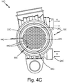
- FIG. 4C is a cross-sectional end view of heated pipe assembly 10C showing pipe 12C and wave shaped screen 14C.
- FIGS. 4A , 4B , and 4C will be discussed together.
- Heated pipe assembly 10C includes pipe 12C and screen 14C.
- Pipe 12C includes first wall 20C, fuel flowpath 22C, and heating fluid inlet 28C.
- Screen 14C includes wave shaped portion 36C (which includes downstream end 38C, upstream end 40C, upstream side 42C, and downstream side 44C) and holes 48C.
- Pipe 12C has the same structure and function as described in reference to pipe 12 in FIGS. 1A , 1B , and 1C .
- Screen 14C has the same structure and function as described in reference to screen 14 in FIGS. 1A , 1B , and 1C except that screen 14C has a wave shape with wave shaped portion 36C instead of a conical shape with conical portion 36, and screen 14C does not include support structure 50.
- screen 14C has wave shaped portion 36C having a wave shape with a periphery connected to first wall 20C.
- Wave shaped portion 36C has downstream end 38C connected to first wall 20C of pipe 12C near heating fluid inlet 28C and upstream end 40C connected to first wall 20C of pipe 12C upstream of downstream end 38C.
- Downstream end 38C meets first wall 20C at an angle
- upstream end 40C meets first wall 20C at an angle
- screen 14C is wave shaped and extends across fuel flowpath 22B such that screen 14C is most perpendicular to first wall 20C near a center portion of screen 14C.
- Upstream side 42C is the upstream surface of wave shaped portion 36C
- downstream side 44C is the downstream surface of wave shaped portion 36C.
- Holes 48C extend from upstream side 42C to downstream side 44C. In this embodiment, holes 48C are polygonal (specifically, hexagonal).
- Ice particles I blocked by wave shaped screen 14C move downstream along screen 14C to a side of pipe 12C connected to a periphery of downstream end 38C. As such, ice particles I are directed to and trapped against a precise portion of an inner diameter of first wall 20C of pipe 12C near heating fluid inlet 28C. Because heating fluid H is hottest at heating fluid inlet 28C and screen 14C directs ice particles I to a precise portion of first wall 20C near heating fluid inlet 28C, ice particles I are directed to a portion of first wall 20C that maximizes thermal exchange. As a result, ice particles I trapped by screen 14C melt and exit heated pipe assembly 10C as water more quickly.
- a pipe assembly includes a first wall having an inner surface defining a fuel flowpath; a second wall spaced radially outward of the first wall; a gap formed between the first wall and the second wall defining a flow passage; and a screen positioned within the fuel flowpath being shaped and configured to direct ice in the fuel flowpath toward the inner surface such that heat from the first wall melts the ice.
- the pipe assembly of the preceding paragraph can optionally include, additionally and/or alternatively, any one or more of the following features, configurations and/or additional components:
- the flow passage is further defined by a rib extending between the first wall and the second wall.
- the rib is helical.
- the flow passage provides a heating flowpath configured to contain a heating fluid to heat the first wall and the screen.
- a heating fluid inlet that receives the heating fluid, the heating fluid inlet extending through the second wall and into the annular gap; and a heating fluid outlet that discharges the heating fluid, the heating fluid outlet extending from the annular gap and through the second wall.
- the pipe assembly is an additively manufactured structure.
- the screen is shaped to trap the ice in the fuel flowpath against the first wall.
- the screen has a conical portion with a downstream end connected to the first wall and an upstream end extending upstream into the fuel flowpath.
- the screen includes a support structure connected to the upstream end of the conical portion and the first wall.
- the screen includes a crossbar extending across a hollow portion within the conical portion.
- the screen is substantially flat and has a downstream end connected to the first wall and an upstream end connected to the first wall.
- the screen has a wave shape with a downstream end connected to the first wall and an upstream end connected to the first wall.
- the screen has holes extending from an upstream side of the screen to a downstream side of the screen.
- the holes have a shape selected from a group consisting of a diamond shape, a circular shape, and a polygonal shape.
- a heated pipe assembly includes a pipe extending from an upstream end to a downstream end; the pipe including: an annular first wall creating a fuel flowpath; an annular second wall radially spaced from the first wall; an annular gap formed between the first wall and the second wall; a heating fluid inlet that receives a heating fluid, the heating fluid inlet extending through the second wall and into the annular gap; a heating fluid outlet that discharges the heating fluid, the heating fluid outlet extending from the annular gap and through the second wall; and a helical rib extending between the first wall and the second wall and defining a flow passage in the annular gap, wherein the flow passage provides a heating flowpath configured to contain the heating fluid to heat the first wall; and a screen connected to the first wall of the pipe and extending across the fuel flowpath, wherein the screen is shaped to direct ice in the fuel flowpath to the first wall and trap the ice against the first wall such that heat from the first wall melts the ice.
- the heated pipe assembly of the preceding paragraph can optionally include, additionally and/or alternatively, any one or more of the following features, configurations and/or additional components:
- the screen includes: a conical portion with a downstream end connected to the first wall and an upstream end extending upstream into the fuel flowpath; a support structure connected to the upstream end of the conical portion and the first wall; and a crossbar extending across a hollow portion within the conical portion.
- the screen is substantially flat and has a downstream end connected to the first wall and an upstream end connected to the first wall.
- the screen has a wave shape with a downstream end connected to the first wall and an upstream end connected to the first wall.
- the screen has holes extending from an upstream side of the screen to a downstream side of the screen, the holes having a shape selected from a group consisting of a diamond shape, a circular shape, and a polygonal shape.
- a method of preventing ice from blocking a fuel flowpath includes urging ice flowing through the fuel flowpath radially outwardly toward an inner surface of a first wall that defines the fuel flowpath; flowing a fluid in a flow passage defined between the first wall and a second wall; increasing a temperature of the inner surface with the flowing of the fluid; and melting the ice.
Abstract
Description
- The present disclosure relates to deicing fuel flowing in a pipe. Ice particles can form in aircraft fuel tanks and front-end components of an engine fuel system. Such ice particles mix with fuel and travel downstream along with the fuel. Ice particles can damage downstream components. As a result, ice is usually melted via electrical heating elements located in the fuel lines. Use of electrical heating elements to melt ice particles flowing with the fuel can be inefficient.
- A pipe assembly includes a first wall having an inner surface defining a fuel flowpath, a second wall spaced radially outward of the first wall, a gap formed between the first wall and the second wall defining a flow passage, and a screen positioned within the fuel flowpath being shaped and configured to direct ice in the fuel flowpath toward the inner surface such that heat from the first wall melts the ice.
- A heated pipe assembly includes a pipe extending from an upstream end to a downstream end and including an annular first wall creating a fuel flowpath, an annular second wall radially spaced from the first wall, an annular gap formed between the first wall and the second wall, a heating fluid inlet that receives a heating fluid, the heating fluid inlet extending through the second wall and into the annular gap, a heating fluid outlet that discharges the heating fluid, the heating fluid outlet extending from the annular gap and through the second wall, and a helical rib extending between the first wall and the second wall and defining a flow passage in the annular gap. The flow passage provides a heating flowpath configured to contain the heating fluid to heat the first wall. The heated pipe assembly further includes a screen connected to the first wall of the pipe and extending across the fuel flowpath. The screen is shaped to direct ice in the fuel flowpath to the first wall and trap the ice against the first wall such that heat from the first wall melts the ice.
- A method of preventing ice from blocking a fuel flowpath includes urging ice flowing through the fuel flowpath radially outwardly toward an inner surface of a first wall that defines the fuel flowpath, flowing a fluid in a flow passage defined between the first wall and a second wall, increasing a temperature of the inner surface with the flowing of the fluid, and melting the ice.
-
-
FIG. 1A is a cross-sectional perspective view of a heated pipe assembly showing a pipe and a screen having a conical shape. -
FIG. 1B is a cross-sectional view of the heated pipe assembly showing the pipe and the screen having a conical shape. -
FIG. 1C is a cross-sectional end view of the heated pipe assembly showing the pipe and the screen having a conical shape. -
FIG. 2 is a cross-sectional perspective view of the heated pipe assembly showing the pipe and a screen with a crossbar. -
FIG. 3A is a cross-sectional perspective view of the heated pipe assembly showing the pipe and an angled flat screen. -
FIG. 3B is a cross-sectional view of the heated pipe assembly showing the pipe and the angled flat screen. -
FIG. 3C is a cross-sectional end view of the heated pipe assembly showing the pipe and the angled flat screen. -
FIG. 4A is a cross-sectional perspective view of the heated pipe assembly showing the pipe and a screen having a wave shape. -
FIG. 4B is a cross-sectional view of the heated pipe assembly showing the pipe and the screen having a wave shape. -
FIG. 4C is a cross-sectional end view of the heated pipe assembly showing the pipe and the screen having a wave shape. - In general, the present disclosure describes a heated screen in the fuel flowpath of a double-walled heated pipe. The screen blocks ice particles in the fuel flowpath and directs the ice particles to the first wall of the heated pipe, trapping the ice particles against the first wall until they melt and flow downstream as water. As a result, ice particles are prevented from clogging or damaging downstream components without requiring electrical heating.
-
FIG. 1A is a cross-sectional perspective view of heatedpipe assembly 10 showingpipe 12 andscreen 14 having a conical shape.FIG. 1B is a cross-sectional view of heatedpipe assembly 10 showingpipe 12 andscreen 14, which has a conical shape.FIG. 1C is a cross-sectional end view of heatedpipe assembly 10 showingpipe 12 and conical shapedscreen 14.FIGS. 1A ,1B , and1C will be discussed together. Heatedpipe assembly 10 includespipe 12 andscreen 14. Pipe 12 includesupstream end 16,downstream end 18,first wall 20,fuel flowpath 22,second wall 24,annular gap 26,heating fluid inlet 28,heating fluid outlet 30,rib 32, andflow passage 34.Screen 14 includes conical portion 36 (which includesdownstream end 38, upstreamend 40,upstream side 42,downstream side 44, and hollow portion 46)holes 48, andsupport structure 50. -
Screen 14 is connected topipe 12 and is made of the same material aspipe 12. As such,pipe 12 andscreen 14 are metal, such as aluminum, stainless steel, Inconel, titanium, or any other suitable metal. In alternate embodiments,pipe 12 andscreen 14 may be made of plastic. Pipe 12 extends fromupstream end 16 to downstreamend 18.Pipe 12 has annular first, or inner,wall 20 extending fromupstream end 16 to downstreamend 18.First wall 20 has an inner surface that creates, or defines,fuel flowpath 22.Fuel flowpath 22 provides a flowpath for fuel F withinpipe 12. Annular second, or outer,wall 24 is spaced radially outward offirst wall 20 such thatfirst wall 20 is withinsecond wall 24. As such,first wall 20 andsecond wall 24 are concentric.Annular gap 26 is an annular space formed betweenfirst wall 20 andsecond wall 24.Heating fluid inlet 28 extends throughsecond wall 24 and intoannular gap 26.Heating fluid inlet 28 is an opening that receives heating fluid H into heatedpipe assembly 10. Heating fluid H is a hot fluid, such as oil or fuel from a downstream heat exchanger.Heating fluid outlet 30 extends fromannular gap 26 throughsecond wall 24.Heating fluid outlet 30 is an opening that discharges heating fluid H from heatedpipe assembly 10.Rib 32 extends betweenfirst wall 20 andsecond wall 24. In this embodiment,rib 32 is helical. In alternate embodiments,rib 32 may be any suitable shape.Rib 32 may be one continuous rib or multiple spaced apart ribs.Annular gap 26 andrib 32 defineflow passage 34 withinannular gap 26.Flow passage 34 provides a heating flowpath inannular gap 26 to contain heating fluid H. -
Screen 14 is connected to an inner surface offirst wall 20 ofpipe 12 and extends acrossfuel flowpath 22. As such,screen 14 is positioned withinfuel flowpath 22. In this embodiment,screen 14 has a conical, or bell, shape. In alternate embodiments,screen 14 may have any suitable shape.Screen 14 hasconical portion 36 with circulardownstream end 38 having a periphery connected tofirst wall 20 andupstream end 40 extending upstream intofuel flowpath 22.Upstream end 40 is not connected tofirst wall 20.Conical portion 36 is shaped like a cone or bell.Upstream side 42 is the upstream surface ofconical portion 36.Downstream side 44 is the downstream surface ofconical portion 36.Downstream side 44 defineshollow portion 46 withinconical portion 36.Hollow portion 46 extends upstream fromdownstream end 38 ofconical portion 36. As such,conical portion 36 is hollow.Holes 48 extend fromupstream side 42 todownstream side 44. In this embodiment, holes 48 are diamond shaped. In alternate embodiments, holes 48 may be circular, polygonal, or any other suitable shape.Support structure 50 is connected toconical portion 36. In this embodiment,support structure 50 includes three legs spaced evenly aroundconical portion 36. In alternate embodiments,support structure 50 may have two, four, or any other suitable number of legs to both maximize strength and minimize weight and cost ofsupport structure 50. First ends of legs are connected toupstream side 42 nearupstream end 40 ofconical portion 36. Second ends of legs are connected tofirst wall 20. In alternate embodiments,screen 14 may not includesupport structure 50.Heated pipe assembly 10, includingpipe 12 andscreen 14, may be additively manufactured. -
Heated pipe assembly 10 is positioned within a fuel system of an aircraft. For example,heated pipe assembly 10 may be located just downstream of a boost pump and upstream of a main fuel pump. - Fuel F moves axially through
fuel flowpath 22 ofpipe 12 fromupstream end 16 todownstream end 18. Fuel F is cold atupstream end 16. Heating fluid H enterspipe 12 atheating fluid inlet 28 and moves, or flows, throughflow passage 34 inannular gap 26 to exitpipe 12 atheating fluid outlet 30. Heating fluid H is warm at heatingfluid inlet 28.Helical rib 32 causes heating fluid H to flow aroundfirst wall 20 in a helical pattern. As such,flow passage 34 provides a heating flowpath to heatfirst wall 20 andscreen 14. Heating fluid H contacts an outer surface offirst wall 20, transferring heat tofirst wall 20 and increasing the temperature of the inner surface offirst wall 20. Consequently, heating fluid H loses heat as heating fluid H moves throughflow passage 34. An inner surface of heatedfirst wall 20contacts screen 14, transferring heat to screen 14. Heatedfirst wall 20 also contacts and transfers heat to fuel F as fuel F moves throughfuel flowpath 22. As such, fuel F is warmer atdownstream end 18 as fuel F exitspipe 12. - Ice particles I may form in aircraft fuel tanks or front-end components of an engine fuel system. Such ice particles I may travel downstream through
fuel flowpath 22 along with fuel F. As a result, fuel F may contain ice particles I atupstream end 16. As fuel F moves throughfuel flowpath 22,screen 14 blocks ice particles I. Ice particles I contactscreen 14 and begin to melt. Ice particles I not fully melted byheated screen 14 move downstream alongscreen 14.Screen 14 is shaped to direct, or urge, ice particles I infuel flowpath 22 radially outwardly toward an inner diameter, or inner surface, offirst wall 20 and trap ice particles I against the inner surface offirst wall 20. As such, ice particles I atupstream side 42 of a periphery of circulardownstream end 38 ofscreen 14 are adjacentfirst wall 20, and heat fromfirst wall 20 melts ice particles I. Heatedscreen 14 may also provide heat to melt ice particles I. As such,heated pipe assembly 10 acts as a heat exchanger between heating fluid H and fuel F with ice particles I. -
Holes 48 allow fuel F to bypassscreen 14. Ice particles I smaller thanholes 48 are also able to bypassscreen 14. Ice particles I larger thanholes 48 are prevented from movingpast screen 14 todownstream end 18. Thus, holes 48 are sized and shaped based on the size of ice particles I that screen 14 is intended to block while also maintaining an appropriate pressure drop.Screen 14 is fine enough thatscreen 14 can capture the desired amount of ice particles I while being coarse enough not to cause a pressure drop acrossscreen 14 high enough that fuel F stops flowing throughfuel flowpath 22. Ice particles I are trapped against heatedfirst wall 20 byheated screen 14 until ice particles I melt. Melted ice particles pass throughscreen 14 as water. - Ice particles may damage downstream components or become problematic within downstream components, such as the fuel metering unit. As a result, ice is usually melted via electrical heating elements located in the fuel lines. For example, fuel heaters may be attached to the pipe, having a heater element positioned around the outside of the pipe to electrically heat the fuel. Electrical heating requires power. Additionally, ice particles can move through a heated pipe assembly without melting by the time the fuel exits the heated pipe assembly.
-
Heated pipe assembly 10 provides an effective in-line method of deicing fuel without requiring electrical heating.Screen 14 also prevents large ice particles from exiting the heated pipe assembly along withfuel F. Screen 14 keeps ice particles I withinheated pipe assembly 10 for a longer amount of time and directs ice particles I to an optimal heat source, heatedfirst wall 20, to cause ice particles I to melt. Therefore, not only are ice particles I caught and trapped byscreen 14 until ice particles I melt, heat is more greatly distributed to ice particles I such that ice particles I melt more quickly. As a result, ice particles I do not accumulate or cause blockage withinheated pipe assembly 10. Ice particles I stay withinfuel flowpath 22 long enough to melt before proceeding as water to the next part of the fuel system. Thus,heated pipe assembly 10 efficiently melts ice particles I, preventing ice particles I from moving downstream and clogging or damaging other components, without resorting to electrical means. -
FIG. 2 is a cross-sectional perspective view ofheated pipe assembly 10A showing pipe 12A andscreen 14A withcrossbar 52.Heated pipe assembly 10A includespipe 12A andscreen 14A.Pipe 12A includesfirst wall 20A.Screen 14A includesconical portion 36A (which includesdownstream end 38A,upstream end 40A, anddownstream side 44A, andhollow portion 46A) andcrossbar 52. -
Pipe 12A has the same structure and function as described in reference topipe 12 inFIGS. 1A ,1B , and1C .Screen 14A has the same structure and function as described in reference toscreen 14 inFIGS. 1A ,1B , and1C except thatscreen 14A also includescrossbar 52.Crossbar 52 is a rod or bar that extends acrosshollow portion 46A withinconical portion 36A. As such, ends ofcrossbar 52 are attached todownstream side 44A ofconical portion 36A. In this embodiment,crossbar 52 is neardownstream end 38A ofconical portion 36. In alternate embodiments,crossbar 52 may be nearupstream end 40A or in any other suitable location withinhollow portion 46A. - Heat from
first wall 20A is transferred tocrossbar 52.Crossbar 52 facilitates heat transfer fromfirst wall 20 throughconical portion 36A. As a result,conical portion 36A is more easily heated and ice particles I that contactheated screen 14A more easily melt. -
FIG. 3A is a cross-sectional perspective view ofheated pipe assembly 10B showing pipe 12B and angledflat screen 14B.FIG. 3B is a cross-sectional view ofheated pipe assembly 10B showing pipe 12B and angledflat screen 14B.FIG. 3C is a cross-sectional end view ofheated pipe assembly 10B showing pipe 12B and angledflat screen 14B.FIGS. 3A ,3B , and3C will be discussed together.Heated pipe assembly 10B includespipe 12B andscreen 14B.Pipe 12B includesfirst wall 20B,fuel flowpath 22B, andheating fluid inlet 28B.Screen 14B includesflat portion 36B (which includesdownstream end 38B,upstream end 40B,upstream side 42B, anddownstream side 44B) and holes 48B. -
Pipe 12B has the same structure and function as described in reference topipe 12 inFIGS. 1A ,1B , and1C .Screen 14B has the same structure and function as described in reference toscreen 14 inFIGS. 1A ,1B , and1C except thatscreen 14B has a flat oval shape withflat portion 36B instead of a conical shape withconical portion 36, andscreen 14B does not includesupport structure 50. In this embodiment,screen 14B hasflat portion 36B having an oval shape with a periphery connected tofirst wall 20B.Flat portion 36B hasdownstream end 38B connected tofirst wall 20B ofpipe 12B nearheating fluid inlet 28B andupstream end 40B connected tofirst wall 20B ofpipe 12B upstream ofdownstream end 38B. As such,screen 14B is substantially flat and extends acrossfuel flowpath 22B at an angle.Upstream side 42B is the upstream surface offlat portion 36B, anddownstream side 44B is the downstream surface offlat portion 36B.Holes 48B extend fromupstream side 42B todownstream side 44B. In this embodiment, holes 48A are circular. - Ice particles I blocked by angled
flat screen 14B move downstream alongscreen 14B to a side ofpipe 12B connected to a periphery ofdownstream end 38B. As such, ice particles I are directed to and trapped against a portion of an inner diameter offirst wall 20B ofpipe 12B nearheating fluid inlet 28B. Because heating fluid H is hottest at heatingfluid inlet 28B andscreen 14B directs ice particles I to a portion offirst wall 20B nearheating fluid inlet 28B, ice particles I are directed to a portion offirst wall 20B that maximizes thermal exchange. As a result, ice particles I trapped byscreen 14B melt and exitheated pipe assembly 10B as water more quickly. -
FIG. 4A is a cross-sectional perspective view ofheated pipe assembly 10C showing pipe 12C andscreen 14C having a wave shape.FIG. 4B is a cross-sectional view ofheated pipe assembly 10C showing pipe 12C andscreen 14C, which has a wave shape.FIG. 4C is a cross-sectional end view ofheated pipe assembly 10C showing pipe 12C and wave shapedscreen 14C.FIGS. 4A ,4B , and4C will be discussed together.Heated pipe assembly 10C includespipe 12C andscreen 14C.Pipe 12C includesfirst wall 20C,fuel flowpath 22C, andheating fluid inlet 28C.Screen 14C includes wave shapedportion 36C (which includesdownstream end 38C,upstream end 40C,upstream side 42C, anddownstream side 44C) and holes 48C. -
Pipe 12C has the same structure and function as described in reference topipe 12 inFIGS. 1A ,1B , and1C .Screen 14C has the same structure and function as described in reference toscreen 14 inFIGS. 1A ,1B , and1C except thatscreen 14C has a wave shape with wave shapedportion 36C instead of a conical shape withconical portion 36, andscreen 14C does not includesupport structure 50. In this embodiment,screen 14C has wave shapedportion 36C having a wave shape with a periphery connected tofirst wall 20C. Wave shapedportion 36C hasdownstream end 38C connected tofirst wall 20C ofpipe 12C nearheating fluid inlet 28C andupstream end 40C connected tofirst wall 20C ofpipe 12C upstream ofdownstream end 38C.Downstream end 38C meetsfirst wall 20C at an angle, andupstream end 40C meetsfirst wall 20C at an angle. As such,screen 14C is wave shaped and extends acrossfuel flowpath 22B such thatscreen 14C is most perpendicular tofirst wall 20C near a center portion ofscreen 14C.Upstream side 42C is the upstream surface of wave shapedportion 36C, anddownstream side 44C is the downstream surface of wave shapedportion 36C.Holes 48C extend fromupstream side 42C todownstream side 44C. In this embodiment, holes 48C are polygonal (specifically, hexagonal). - Ice particles I blocked by wave shaped
screen 14C move downstream alongscreen 14C to a side ofpipe 12C connected to a periphery ofdownstream end 38C. As such, ice particles I are directed to and trapped against a precise portion of an inner diameter offirst wall 20C ofpipe 12C nearheating fluid inlet 28C. Because heating fluid H is hottest at heatingfluid inlet 28C andscreen 14C directs ice particles I to a precise portion offirst wall 20C nearheating fluid inlet 28C, ice particles I are directed to a portion offirst wall 20C that maximizes thermal exchange. As a result, ice particles I trapped byscreen 14C melt and exitheated pipe assembly 10C as water more quickly. - The following are non-exclusive descriptions of possible embodiments of the present invention.
- A pipe assembly includes a first wall having an inner surface defining a fuel flowpath; a second wall spaced radially outward of the first wall; a gap formed between the first wall and the second wall defining a flow passage; and a screen positioned within the fuel flowpath being shaped and configured to direct ice in the fuel flowpath toward the inner surface such that heat from the first wall melts the ice.
- The pipe assembly of the preceding paragraph can optionally include, additionally and/or alternatively, any one or more of the following features, configurations and/or additional components:
The flow passage is further defined by a rib extending between the first wall and the second wall. - The rib is helical.
- The flow passage provides a heating flowpath configured to contain a heating fluid to heat the first wall and the screen.
- A heating fluid inlet that receives the heating fluid, the heating fluid inlet extending through the second wall and into the annular gap; and a heating fluid outlet that discharges the heating fluid, the heating fluid outlet extending from the annular gap and through the second wall.
- The pipe assembly is an additively manufactured structure.
- The screen is shaped to trap the ice in the fuel flowpath against the first wall.
- The screen has a conical portion with a downstream end connected to the first wall and an upstream end extending upstream into the fuel flowpath.
- The screen includes a support structure connected to the upstream end of the conical portion and the first wall.
- The screen includes a crossbar extending across a hollow portion within the conical portion.
- The screen is substantially flat and has a downstream end connected to the first wall and an upstream end connected to the first wall.
- The screen has a wave shape with a downstream end connected to the first wall and an upstream end connected to the first wall.
- The screen has holes extending from an upstream side of the screen to a downstream side of the screen.
- The holes have a shape selected from a group consisting of a diamond shape, a circular shape, and a polygonal shape.
- A heated pipe assembly includes a pipe extending from an upstream end to a downstream end; the pipe including: an annular first wall creating a fuel flowpath; an annular second wall radially spaced from the first wall; an annular gap formed between the first wall and the second wall; a heating fluid inlet that receives a heating fluid, the heating fluid inlet extending through the second wall and into the annular gap; a heating fluid outlet that discharges the heating fluid, the heating fluid outlet extending from the annular gap and through the second wall; and a helical rib extending between the first wall and the second wall and defining a flow passage in the annular gap, wherein the flow passage provides a heating flowpath configured to contain the heating fluid to heat the first wall; and a screen connected to the first wall of the pipe and extending across the fuel flowpath, wherein the screen is shaped to direct ice in the fuel flowpath to the first wall and trap the ice against the first wall such that heat from the first wall melts the ice.
- The heated pipe assembly of the preceding paragraph can optionally include, additionally and/or alternatively, any one or more of the following features, configurations and/or additional components:
- The screen includes: a conical portion with a downstream end connected to the first wall and an upstream end extending upstream into the fuel flowpath; a support structure connected to the upstream end of the conical portion and the first wall; and a crossbar extending across a hollow portion within the conical portion.
- The screen is substantially flat and has a downstream end connected to the first wall and an upstream end connected to the first wall.
- The screen has a wave shape with a downstream end connected to the first wall and an upstream end connected to the first wall.
- The screen has holes extending from an upstream side of the screen to a downstream side of the screen, the holes having a shape selected from a group consisting of a diamond shape, a circular shape, and a polygonal shape.
- A method of preventing ice from blocking a fuel flowpath includes urging ice flowing through the fuel flowpath radially outwardly toward an inner surface of a first wall that defines the fuel flowpath; flowing a fluid in a flow passage defined between the first wall and a second wall; increasing a temperature of the inner surface with the flowing of the fluid; and melting the ice.
- While the invention has been described with reference to an exemplary embodiment(s), it will be understood by those skilled in the art that various changes may be made and equivalents may be substituted for elements thereof without departing from the scope of the invention as defined by the claims. In addition, many modifications may be made to adapt a particular situation or material to the teachings of the invention without departing from the scope of the claims. Therefore, it is intended that the invention not be limited to the particular embodiment(s) disclosed, but that the invention will include all embodiments falling within the scope of the appended claims.
Claims (15)
- A pipe assembly comprising:a first wall (20) having an inner surface defining a fuel flowpath (22);a second wall (24) spaced radially outward of the first wall;a gap (26) formed between the first wall and the second wall defining a flow passage; anda screen (14) positioned within the fuel flowpath being shaped and configured to direct ice in the fuel flowpath toward the inner surface such that heat from the first wall melts the ice.
- The pipe assembly of claim 1, wherein the flow passage is further defined by a rib (32) extending between the first wall and the second wall.
- The pipe assembly of claim 2, wherein the rib (32) is helical.
- The pipe assembly of claim 1, 2or 3, wherein the flow passage provides a heating flowpath configured to contain a heating fluid to heat the first wall and the screen.
- The pipe assembly of claim 4, and further including a heating fluid inlet (38) that receives the heating fluid, the heating fluid inlet extending through the second wall and into the gap; and a heating fluid outlet (30) that discharges the heating fluid, the heating fluid outlet extending from the gap and through the second wall.
- The pipe assembly of any preceding claim, wherein the pipe assembly is an additively manufactured structure.
- The pipe assembly of any preceding claim, wherein the screen (14) is shaped to trap the ice in the fuel flowpath against the first wall.
- The pipe assembly of any preceding claim, wherein the screen (14) has a conical portion (36) with a downstream end connected to the first wall and an upstream end extending upstream into the fuel flowpath.
- The pipe assembly of claim 8, wherein the screen includes a support structure (50) connected to the upstream end of the conical portion and the first wall.
- The pipe assembly of claim 8, wherein the screen includes a crossbar (52) extending across a hollow portion within the conical portion.
- The pipe assembly of any preceding claim, wherein the screen is substantially flat and has a downstream end connected to the first wall and an upstream end connected to the first wall, or wherein the screen has a wave shape with a downstream end connected to the first wall and an upstream end connected to the first wall.
- The pipe assembly of any preceding claim, wherein the screen has holes (48) extending from an upstream side of the screen to a downstream side of the screen.
- The pipe assembly of claim 12, wherein the holes (48) have a shape selected from a group consisting of a diamond shape, a circular shape, and a polygonal shape.
- A pipe assembly as claimed in claim 5, dependent on claim 3, or any claim dependent thereon, being a heated pipe assembly, and comprising:a pipe (12) extending from an upstream end to a downstream end; the pipe including:the first wall being an annular first wall (20) creating the fuel flowpath (22);the second wall being an annular second wall (24) radially spaced from the first wall;the gap being an annular gap (26) formed between the first wall and the second wall; andthe screen being connected to the first wall of the pipe and extending across the fuel flowpath, wherein the screen is shaped to direct ice in the fuel flowpath to the first wall and trap the ice against the first wall such that heat from the first wall melts the ice.
- A method of preventing ice from blocking a fuel flowpath comprising:urging ice flowing through the fuel flowpath radially outwardly toward an inner surface of a first wall that defines the fuel flowpath;flowing a fluid in a flow passage defined between the first wall and a second wall;increasing a temperature of the inner surface with the flowing of the fluid; andmelting the ice.
Priority Applications (1)
| Application Number | Priority Date | Filing Date | Title |
|---|---|---|---|
| EP23189635.8A EP4296555A1 (en) | 2018-07-10 | 2019-07-10 | Heated pipe for liquid flows |
Applications Claiming Priority (1)
| Application Number | Priority Date | Filing Date | Title |
|---|---|---|---|
| US16/031,573 US10703500B2 (en) | 2018-07-10 | 2018-07-10 | Heated pipe for liquid flows |
Related Child Applications (1)
| Application Number | Title | Priority Date | Filing Date |
|---|---|---|---|
| EP23189635.8A Division EP4296555A1 (en) | 2018-07-10 | 2019-07-10 | Heated pipe for liquid flows |
Publications (2)
| Publication Number | Publication Date |
|---|---|
| EP3594550A1 true EP3594550A1 (en) | 2020-01-15 |
| EP3594550B1 EP3594550B1 (en) | 2023-08-30 |
Family
ID=67226157
Family Applications (2)
| Application Number | Title | Priority Date | Filing Date |
|---|---|---|---|
| EP19185509.7A Active EP3594550B1 (en) | 2018-07-10 | 2019-07-10 | Heated pipe for liquid flows |
| EP23189635.8A Pending EP4296555A1 (en) | 2018-07-10 | 2019-07-10 | Heated pipe for liquid flows |
Family Applications After (1)
| Application Number | Title | Priority Date | Filing Date |
|---|---|---|---|
| EP23189635.8A Pending EP4296555A1 (en) | 2018-07-10 | 2019-07-10 | Heated pipe for liquid flows |
Country Status (2)
| Country | Link |
|---|---|
| US (1) | US10703500B2 (en) |
| EP (2) | EP3594550B1 (en) |
Cited By (2)
| Publication number | Priority date | Publication date | Assignee | Title |
|---|---|---|---|---|
| CN113819334A (en) * | 2021-10-09 | 2021-12-21 | 济南睿达物联网有限公司 | Heat-insulation water pipe capable of being heated |
| EP4194701A1 (en) * | 2021-12-08 | 2023-06-14 | Hamilton Sundstrand Corporation | Pump filter with predetermined swirl |
Families Citing this family (4)
| Publication number | Priority date | Publication date | Assignee | Title |
|---|---|---|---|---|
| US11274853B2 (en) * | 2018-10-15 | 2022-03-15 | Goodrich Corporation | Additively manufactured heaters for water system components |
| US11841103B2 (en) * | 2021-04-09 | 2023-12-12 | Globalfoundries U.S. Inc. | Pipe assembly having an angled plate and fabrication methods |
| US20220355227A1 (en) * | 2021-05-05 | 2022-11-10 | Hamilton Sundstrand Corporation | Monolithic additively manufactured pump inlet housing and filter |
| CN114593629B (en) * | 2022-05-10 | 2022-07-22 | 中国飞机强度研究所 | Heat exchanger anti-icing system for aircraft test and operation method thereof |
Citations (5)
| Publication number | Priority date | Publication date | Assignee | Title |
|---|---|---|---|---|
| US2549687A (en) * | 1947-11-21 | 1951-04-17 | Duriron Co | Heat exchanger |
| US5588635A (en) * | 1994-08-26 | 1996-12-31 | Hartman; Thomas A. | Liquid flow velocity diffuser |
| JP2001201275A (en) * | 2000-01-21 | 2001-07-27 | Daikin Ind Ltd | Double tube heat exchanger |
| CN104006259B (en) * | 2014-05-20 | 2016-03-02 | 国家电网公司 | Pump-storage generator labyrinth ring water supply line noise reduction system |
| CN105571356A (en) * | 2016-01-18 | 2016-05-11 | 太原理工大学 | Rib/spiral piece combined double-pipe heat exchanger |
Family Cites Families (36)
| Publication number | Priority date | Publication date | Assignee | Title |
|---|---|---|---|---|
| US383536A (en) * | 1888-05-29 | Thermo-electric apparatus for controlling the temperature of water in pipes | ||
| US745060A (en) * | 1902-02-24 | 1903-11-24 | Anti Bursting Pipe Company | Means for protecting water-pipes against bursting by freezing. |
| US791453A (en) * | 1905-03-02 | 1905-06-06 | Richard S Cuddihy | Drain-pipe. |
| US1112154A (en) * | 1914-06-15 | 1914-09-29 | Thomas G Mouat | Return-fitting for vapor-heating systems. |
| US3509917A (en) * | 1968-03-25 | 1970-05-05 | Kal Pac Eng Ltd | Exhaust antifreeze structure for pneumatically powered apparatus |
| US3643733A (en) | 1970-02-05 | 1972-02-22 | Roger W Hall | Heat exchanger |
| IT1029921B (en) | 1974-03-07 | 1979-03-20 | Mtu Friedrichshafen Gmbh | DOUBLE WALL HIGH PRESSURE DUCT |
| US4218999A (en) | 1977-09-09 | 1980-08-26 | Shearer Kenneth O | Inline fuel heater |
| US4365404A (en) * | 1979-04-20 | 1982-12-28 | The Dow Chemical Company | Making jacketed lined pipe |
| US4258782A (en) | 1979-06-28 | 1981-03-31 | Modine Manufacturing Company | Heat exchanger having liquid turbulator |
| US4381819A (en) | 1979-09-14 | 1983-05-03 | Paolino Ralph J | Flue heat reclaimer |
| US5127441A (en) | 1985-12-16 | 1992-07-07 | Rains Robert L | Coaxial piping system |
| US4915121A (en) | 1987-11-12 | 1990-04-10 | Rains Robert L | Coaxial piping system |
| DE8800949U1 (en) | 1988-01-27 | 1988-03-10 | Rehau Ag + Co, 8673 Rehau, De | |
| DE9004539U1 (en) | 1990-04-21 | 1990-09-20 | Senk, Werner, 5465 Erpel, De | |
| RU2225807C2 (en) | 2002-02-08 | 2004-03-20 | Открытое акционерное общество Производственно-конструкторское объединение "Теплообменник" | Fuel heater for heating fuel in flying vehicle tank |
| DE10234043A1 (en) | 2002-07-26 | 2004-02-05 | Forschungszentrum Karlsruhe Gmbh | Microstructure apparatus for heating a fluid |
| GB2440546A (en) | 2006-08-04 | 2008-02-06 | Rolls Royce Plc | Fluid carrying arrangement and its manufacture using a solid freeform fabrication process |
| GB0904171D0 (en) * | 2009-03-11 | 2009-04-22 | Airbus Uk Ltd | Cyclonic separator |
| FR2960955A1 (en) | 2010-06-04 | 2011-12-09 | Airbus Operations Sas | PREHEATING DEVICE FOR A FLUID / FLUID HEAT EXCHANGER OF AN AIRCRAFT |
| US20130068704A1 (en) | 2011-09-19 | 2013-03-21 | Behzad Hagshenas | Fuel system ice separator |
| RU2514522C2 (en) | 2012-02-03 | 2014-04-27 | Федеральное государственное бюджетное образовательное учреждение высшего профессионального образования "Воронежский государственный технический университет" | Method of controlling fuel feed to gas turbine engine |
| GB201204752D0 (en) | 2012-03-19 | 2012-05-02 | Bae Systems Plc | Additive layer manufacturing |
| GB2511914B (en) | 2013-01-17 | 2015-09-23 | Bae Systems Plc | Object production |
| ES2758081T3 (en) | 2013-02-21 | 2020-05-04 | United Technologies Corp | Removal of inhomogeneous ice from a fuel system |
| DE102013203936A1 (en) | 2013-03-07 | 2014-09-11 | Airbus Operations Gmbh | Generative layer building method for producing a three-dimensional object and three-dimensional object |
| US9310023B2 (en) | 2013-06-20 | 2016-04-12 | The Boeing Company | Methods and systems for distributing inert gas in an aircraft |
| US20160238324A1 (en) | 2013-09-23 | 2016-08-18 | United Technologies Corporation | Method of generating support structure of tube components to become functional features |
| WO2015130356A2 (en) | 2013-12-16 | 2015-09-03 | United Technologies Corporation | Ice tolerant gas turbine fuel systems |
| GB201401581D0 (en) | 2014-01-30 | 2014-03-19 | Rolls Royce Plc | A fuel manifold and fuel injector arrangement |
| AU2015255929B2 (en) | 2014-05-07 | 2019-07-18 | Glen R. Sumner | Submarine or buried piping and pipelines insulated with liquids |
| US10934890B2 (en) | 2014-05-09 | 2021-03-02 | Raytheon Technologies Corporation | Shrouded conduit for arranging a fluid flowpath |
| US9759356B2 (en) | 2014-07-03 | 2017-09-12 | United Technologies Corporation | Insulated flowpath assembly |
| FR3029595B1 (en) * | 2014-12-08 | 2017-06-16 | Airbus Operations Sas | ANTIFREEZE SYSTEM FOR A CANALIZATION |
| EP3086011B1 (en) | 2015-04-21 | 2019-07-31 | Airbus Operations GmbH | Double-walled pipe with integrated heating capability for an aircraft or spacecraft |
| EP3290766B1 (en) | 2016-09-01 | 2021-03-03 | Microtecnica S.r.l. | Aircraft environmental control system with double-walled pipe and method |
-
2018
- 2018-07-10 US US16/031,573 patent/US10703500B2/en active Active
-
2019
- 2019-07-10 EP EP19185509.7A patent/EP3594550B1/en active Active
- 2019-07-10 EP EP23189635.8A patent/EP4296555A1/en active Pending
Patent Citations (5)
| Publication number | Priority date | Publication date | Assignee | Title |
|---|---|---|---|---|
| US2549687A (en) * | 1947-11-21 | 1951-04-17 | Duriron Co | Heat exchanger |
| US5588635A (en) * | 1994-08-26 | 1996-12-31 | Hartman; Thomas A. | Liquid flow velocity diffuser |
| JP2001201275A (en) * | 2000-01-21 | 2001-07-27 | Daikin Ind Ltd | Double tube heat exchanger |
| CN104006259B (en) * | 2014-05-20 | 2016-03-02 | 国家电网公司 | Pump-storage generator labyrinth ring water supply line noise reduction system |
| CN105571356A (en) * | 2016-01-18 | 2016-05-11 | 太原理工大学 | Rib/spiral piece combined double-pipe heat exchanger |
Cited By (3)
| Publication number | Priority date | Publication date | Assignee | Title |
|---|---|---|---|---|
| CN113819334A (en) * | 2021-10-09 | 2021-12-21 | 济南睿达物联网有限公司 | Heat-insulation water pipe capable of being heated |
| CN113819334B (en) * | 2021-10-09 | 2023-01-13 | 济南睿达物联网有限公司 | Heat-insulation water pipe capable of being heated |
| EP4194701A1 (en) * | 2021-12-08 | 2023-06-14 | Hamilton Sundstrand Corporation | Pump filter with predetermined swirl |
Also Published As
| Publication number | Publication date |
|---|---|
| EP3594550B1 (en) | 2023-08-30 |
| US20200017231A1 (en) | 2020-01-16 |
| EP4296555A1 (en) | 2023-12-27 |
| US10703500B2 (en) | 2020-07-07 |
Similar Documents
| Publication | Publication Date | Title |
|---|---|---|
| EP3594550B1 (en) | Heated pipe for liquid flows | |
| EP1115542B1 (en) | Thermoplastic material melting unit having high throughput and heating capacity | |
| EP3394522B1 (en) | Fired heat exchanger | |
| US8091514B2 (en) | Energy re-claimer | |
| EP2439476A2 (en) | Heat exchanger for air conditioning systems comprising a conduit with longitudinal fins | |
| US4825940A (en) | Automatic process and device for cleaning a heat exchanger for gaseous fluids | |
| SE1850722A1 (en) | Self-cleaning ventilation unit | |
| US20030178185A1 (en) | Heat exchanger with reduced fouling | |
| US10935322B2 (en) | Shell and tube heat exchanger with perforated fins interconnecting the tubes | |
| EP2314947B1 (en) | Solid fuel burning device with heat exchanger for transferring heat to a fluid circuit | |
| EP3188629B1 (en) | Instantaneous water heater for a hot beverage preparation device | |
| DE102008059541A1 (en) | Heat exchanger for exchanging heat between two heat transferring mediums, comprises heat transferring medium through flow channel, where heat exchanger tube is provided for passing another heat transferring medium | |
| CN111006426A (en) | Cooling arrangement for engineering | |
| JP5786242B2 (en) | Snow melting equipment for a multi-storey greenhouse | |
| CA2843663C (en) | Continuous flow multi stage gas contact water heater | |
| US20150233587A1 (en) | Heat exchanger and method for demisting | |
| EP4332486A1 (en) | Heat exchanger and a method for its production | |
| EP1004832A2 (en) | Electric heater for fluids, in particular paints | |
| JPH0914702A (en) | Ice heat accumulating unit device and its operating method | |
| DE3013599A1 (en) | DEVICE FOR FUNCTIONAL TESTING OF THERMAL FIRE DETECTORS | |
| CN107001041B (en) | Device and method for cooling a fluid | |
| CN103884088B (en) | Warm water heater in warm water sanitary equipment and include its warm water feeding mechanism | |
| EP3256794B1 (en) | Heat exchanger element and method for manufacturing such a heat exchanger element | |
| CN111089321A (en) | Thermal oil removal oil net | |
| RU2302286C1 (en) | Device for droplet generation of granulator |
Legal Events
| Date | Code | Title | Description |
|---|---|---|---|
| PUAI | Public reference made under article 153(3) epc to a published international application that has entered the european phase |
Free format text: ORIGINAL CODE: 0009012 |
|
| STAA | Information on the status of an ep patent application or granted ep patent |
Free format text: STATUS: THE APPLICATION HAS BEEN PUBLISHED |
|
| AK | Designated contracting states |
Kind code of ref document: A1 Designated state(s): AL AT BE BG CH CY CZ DE DK EE ES FI FR GB GR HR HU IE IS IT LI LT LU LV MC MK MT NL NO PL PT RO RS SE SI SK SM TR |
|
| AX | Request for extension of the european patent |
Extension state: BA ME |
|
| STAA | Information on the status of an ep patent application or granted ep patent |
Free format text: STATUS: REQUEST FOR EXAMINATION WAS MADE |
|
| 17P | Request for examination filed |
Effective date: 20200715 |
|
| RBV | Designated contracting states (corrected) |
Designated state(s): AL AT BE BG CH CY CZ DE DK EE ES FI FR GB GR HR HU IE IS IT LI LT LU LV MC MK MT NL NO PL PT RO RS SE SI SK SM TR |
|
| STAA | Information on the status of an ep patent application or granted ep patent |
Free format text: STATUS: EXAMINATION IS IN PROGRESS |
|
| 17Q | First examination report despatched |
Effective date: 20211021 |
|
| GRAP | Despatch of communication of intention to grant a patent |
Free format text: ORIGINAL CODE: EPIDOSNIGR1 |
|
| STAA | Information on the status of an ep patent application or granted ep patent |
Free format text: STATUS: GRANT OF PATENT IS INTENDED |
|
| RIC1 | Information provided on ipc code assigned before grant |
Ipc: F28D 7/10 20060101ALI20230315BHEP Ipc: F28F 1/36 20060101ALI20230315BHEP Ipc: F16L 55/027 20060101ALI20230315BHEP Ipc: F02M 31/125 20060101ALI20230315BHEP Ipc: B64D 37/32 20060101ALI20230315BHEP Ipc: F16L 9/18 20060101ALI20230315BHEP Ipc: F16L 53/32 20180101ALI20230315BHEP Ipc: F16L 53/30 20180101AFI20230315BHEP |
|
| INTG | Intention to grant announced |
Effective date: 20230328 |
|
| GRAS | Grant fee paid |
Free format text: ORIGINAL CODE: EPIDOSNIGR3 |
|
| GRAA | (expected) grant |
Free format text: ORIGINAL CODE: 0009210 |
|
| STAA | Information on the status of an ep patent application or granted ep patent |
Free format text: STATUS: THE PATENT HAS BEEN GRANTED |
|
| AK | Designated contracting states |
Kind code of ref document: B1 Designated state(s): AL AT BE BG CH CY CZ DE DK EE ES FI FR GB GR HR HU IE IS IT LI LT LU LV MC MK MT NL NO PL PT RO RS SE SI SK SM TR |
|
| REG | Reference to a national code |
Ref country code: GB Ref legal event code: FG4D |
|
| REG | Reference to a national code |
Ref country code: CH Ref legal event code: EP |
|
| REG | Reference to a national code |
Ref country code: DE Ref legal event code: R096 Ref document number: 602019035962 Country of ref document: DE |
|
| REG | Reference to a national code |
Ref country code: IE Ref legal event code: FG4D |
|
| REG | Reference to a national code |
Ref country code: LT Ref legal event code: MG9D |
|
| REG | Reference to a national code |
Ref country code: NL Ref legal event code: MP Effective date: 20230830 |
|
| REG | Reference to a national code |
Ref country code: AT Ref legal event code: MK05 Ref document number: 1605854 Country of ref document: AT Kind code of ref document: T Effective date: 20230830 |
|
| PG25 | Lapsed in a contracting state [announced via postgrant information from national office to epo] |
Ref country code: GR Free format text: LAPSE BECAUSE OF FAILURE TO SUBMIT A TRANSLATION OF THE DESCRIPTION OR TO PAY THE FEE WITHIN THE PRESCRIBED TIME-LIMIT Effective date: 20231201 |
|
| PG25 | Lapsed in a contracting state [announced via postgrant information from national office to epo] |
Ref country code: IS Free format text: LAPSE BECAUSE OF FAILURE TO SUBMIT A TRANSLATION OF THE DESCRIPTION OR TO PAY THE FEE WITHIN THE PRESCRIBED TIME-LIMIT Effective date: 20231230 |
|
| PG25 | Lapsed in a contracting state [announced via postgrant information from national office to epo] |
Ref country code: SE Free format text: LAPSE BECAUSE OF FAILURE TO SUBMIT A TRANSLATION OF THE DESCRIPTION OR TO PAY THE FEE WITHIN THE PRESCRIBED TIME-LIMIT Effective date: 20230830 Ref country code: RS Free format text: LAPSE BECAUSE OF FAILURE TO SUBMIT A TRANSLATION OF THE DESCRIPTION OR TO PAY THE FEE WITHIN THE PRESCRIBED TIME-LIMIT Effective date: 20230830 Ref country code: NO Free format text: LAPSE BECAUSE OF FAILURE TO SUBMIT A TRANSLATION OF THE DESCRIPTION OR TO PAY THE FEE WITHIN THE PRESCRIBED TIME-LIMIT Effective date: 20231130 Ref country code: LV Free format text: LAPSE BECAUSE OF FAILURE TO SUBMIT A TRANSLATION OF THE DESCRIPTION OR TO PAY THE FEE WITHIN THE PRESCRIBED TIME-LIMIT Effective date: 20230830 Ref country code: LT Free format text: LAPSE BECAUSE OF FAILURE TO SUBMIT A TRANSLATION OF THE DESCRIPTION OR TO PAY THE FEE WITHIN THE PRESCRIBED TIME-LIMIT Effective date: 20230830 Ref country code: IS Free format text: LAPSE BECAUSE OF FAILURE TO SUBMIT A TRANSLATION OF THE DESCRIPTION OR TO PAY THE FEE WITHIN THE PRESCRIBED TIME-LIMIT Effective date: 20231230 Ref country code: HR Free format text: LAPSE BECAUSE OF FAILURE TO SUBMIT A TRANSLATION OF THE DESCRIPTION OR TO PAY THE FEE WITHIN THE PRESCRIBED TIME-LIMIT Effective date: 20230830 Ref country code: GR Free format text: LAPSE BECAUSE OF FAILURE TO SUBMIT A TRANSLATION OF THE DESCRIPTION OR TO PAY THE FEE WITHIN THE PRESCRIBED TIME-LIMIT Effective date: 20231201 Ref country code: FI Free format text: LAPSE BECAUSE OF FAILURE TO SUBMIT A TRANSLATION OF THE DESCRIPTION OR TO PAY THE FEE WITHIN THE PRESCRIBED TIME-LIMIT Effective date: 20230830 Ref country code: AT Free format text: LAPSE BECAUSE OF FAILURE TO SUBMIT A TRANSLATION OF THE DESCRIPTION OR TO PAY THE FEE WITHIN THE PRESCRIBED TIME-LIMIT Effective date: 20230830 |
|
| PG25 | Lapsed in a contracting state [announced via postgrant information from national office to epo] |
Ref country code: PL Free format text: LAPSE BECAUSE OF FAILURE TO SUBMIT A TRANSLATION OF THE DESCRIPTION OR TO PAY THE FEE WITHIN THE PRESCRIBED TIME-LIMIT Effective date: 20230830 Ref country code: NL Free format text: LAPSE BECAUSE OF FAILURE TO SUBMIT A TRANSLATION OF THE DESCRIPTION OR TO PAY THE FEE WITHIN THE PRESCRIBED TIME-LIMIT Effective date: 20230830 |