EP4194272A1 - Sliding glove box - Google Patents
Sliding glove box Download PDFInfo
- Publication number
- EP4194272A1 EP4194272A1 EP22163598.0A EP22163598A EP4194272A1 EP 4194272 A1 EP4194272 A1 EP 4194272A1 EP 22163598 A EP22163598 A EP 22163598A EP 4194272 A1 EP4194272 A1 EP 4194272A1
- Authority
- EP
- European Patent Office
- Prior art keywords
- glove box
- rail
- disposed
- wheels
- wheel
- Prior art date
- Legal status (The legal status is an assumption and is not a legal conclusion. Google has not performed a legal analysis and makes no representation as to the accuracy of the status listed.)
- Granted
Links
Images



Classifications
-
- B—PERFORMING OPERATIONS; TRANSPORTING
- B60—VEHICLES IN GENERAL
- B60R—VEHICLES, VEHICLE FITTINGS, OR VEHICLE PARTS, NOT OTHERWISE PROVIDED FOR
- B60R7/00—Stowing or holding appliances inside vehicle primarily intended for personal property smaller than suit-cases, e.g. travelling articles, or maps
- B60R7/04—Stowing or holding appliances inside vehicle primarily intended for personal property smaller than suit-cases, e.g. travelling articles, or maps in driver or passenger space, e.g. using racks
- B60R7/06—Stowing or holding appliances inside vehicle primarily intended for personal property smaller than suit-cases, e.g. travelling articles, or maps in driver or passenger space, e.g. using racks mounted on or below dashboards
-
- B—PERFORMING OPERATIONS; TRANSPORTING
- B60—VEHICLES IN GENERAL
- B60R—VEHICLES, VEHICLE FITTINGS, OR VEHICLE PARTS, NOT OTHERWISE PROVIDED FOR
- B60R11/00—Arrangements for holding or mounting articles, not otherwise provided for
- B60R2011/0001—Arrangements for holding or mounting articles, not otherwise provided for characterised by position
- B60R2011/0003—Arrangements for holding or mounting articles, not otherwise provided for characterised by position inside the vehicle
- B60R2011/0005—Dashboard
-
- B—PERFORMING OPERATIONS; TRANSPORTING
- B60—VEHICLES IN GENERAL
- B60R—VEHICLES, VEHICLE FITTINGS, OR VEHICLE PARTS, NOT OTHERWISE PROVIDED FOR
- B60R11/00—Arrangements for holding or mounting articles, not otherwise provided for
- B60R2011/0042—Arrangements for holding or mounting articles, not otherwise provided for characterised by mounting means
- B60R2011/008—Adjustable or movable supports
- B60R2011/0084—Adjustable or movable supports with adjustment by linear movement in their operational position
Definitions
- the present disclosure relates to a sliding glove box. More specifically, the present disclosure relates to a sliding glove box in which a problem occurring in a double rail or single rail of a glove box of a closed type design is solved.
- an instrument panel called a dashboard is installed in front of a driver's seat of a vehicle, and an instrument cluster, in which various instruments and warning lights aiding in more safe driving of the vehicle by allowing a driver to frequently check a state of the traveling vehicle to drive the vehicle more stably and smoothly are gathered, is installed on the instrument panel.
- a tachometer for displaying revolutions per minute (RPM) of an engine to aid the driver in selecting a time of changing speed determined by the driver while traveling and to recognize an over rotation state of the engine to prevent the over rotation state
- a speedometer for displaying a vehicle running speed to prevent overspeed
- a trip odometer for displaying a traveling distance of the vehicle, a cumulative odometer, and the like are installed.
- various attention warning lights such as a turn indicator lamp, an emergency warning lamp, a battery warning lamp which is turned on when a battery is not charged, and a warning lamp which is turned on when an amount of engine oil is low as well as a thermometer for displaying an engine coolant temperature, and a fuel gauge for displaying a remaining fuel in a fuel tank are gathered, and various levers or buttons necessary for operating heating and cooling devices such as a heater and an air conditioner are installed at a right side of the instrument cluster.
- the glove box may be divided into an open type glove box or closed type glove box.
- the present disclosure is directed to solving a problem occurring when a double rail or single rail is applied to a closed type glove box.
- a sliding glove box may include a glove box including an inner space for accommodating an object and a case which accommodates the glove box, in which a plurality of wheels are disposed at each of two sides of the glove box, the plurality of wheels move on a rail disposed in the case, and at least one of the plurality of wheels includes one side that is in contact with the rail.
- the rail may have a " ⁇ " shape, and the wheel may be disposed in an accommodation space formed in the rail.
- the plurality of wheels may be installed on fixing brackets and fixed to fixing parts disposed at the two sides of the glove box.
- the fixing parts may protrude from a lower portion of the glove box.
- the rail may be disposed in a groove formed in a lower surface of the case.
- the number of the plurality of wheels may be at least three, and each of the plurality of wheels may be in contract with any one side of an upper portion or a lower portion of the rail.
- the plurality of wheels may be disposed to be alternately in contact with the upper portion and the lower portion of the rail.
- a stopper may be disposed on an end portion of the rail, and a bumper may be disposed at one side of one of the fixing parts.
- At least one of the stopper or the bumper may include an elastic material.
- An accommodation groove may be disposed in the wheel, and protruding parts mat be inserted into the accommodation groove.
- any one element is described as being formed or disposed "on or under” another element
- such a description includes both a case in which the two elements are formed or disposed in direct contact with each other and a case in which one or more other elements are interposed between the two elements.
- such a description may include a case in which the one element is disposed at an upper side or a lower side with respect to another element.
- FIGS. 1 to 9 are views clearly illustrating main feature portions in order to conceptually and clearly understand the present disclosure, and thus, various modifications of the drawings are expected, and the scope of the present disclosure is not necessarily limited by specific shapes illustrated in the drawings.
- FIG. 1 is a perspective view illustrating a sliding glove box according to an embodiment of the present disclosure
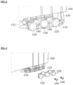
- FIG. 2 is a view illustrating a state in which components of FIG. 1 are separated
- FIG. 3 is a view illustrating a wheel installation structure of the glove box which is a component of FIG. 2
- FIG. 4 is an exploded perspective view illustrating the wheel installation structure of FIG. 3
- FIG. 5 is a view illustrating a structure of a case which is a component of FIG. 2
- FIG. 6 is a view illustrating a coupling structure of a wheel and a rail in FIG. 1
- FIG. 7 is a view illustrating a structure of a stopper disposed in the case of FIG. 2
- FIGS. 8 and 9 are views illustrating examples of a layout of the wheel which is a component of FIG. 2 .
- a sliding glove box 1 may include a glove box 100 and a case 200.
- the glove box 100 includes an inner space capable of accommodating an object.
- the glove box 100 may include a handle 101 for opening or closing the glove box 100.
- a plurality of wheels 120 may be disposed on each side surface of the glove box 100.
- the plurality of wheels 120 may be disposed to stably move along rails 210, and at least three wheels 120 may be disposed on each of the both side surfaces of the glove box 100 in order to prevent vertical movement when moving on the rail 210.
- the wheel 120 may have a structure directly installed on the glove box 100. However, the wheels 120 may be fixed to the glove box 100 using separate fixing brackets 110 for ease of operation to easily replace the wheel 120 when the wheel 120 is broken.
- the fixing brackets 110 may be fixed to fixing parts 130 disposed at two sides of the glove box 100.
- the fixing part 130 may be provided as a structure protruding from a lower portion of the glove box 100 such that the volume of the inner space of the glove box 100 is not decreased, and thus the utilization of the inner space of the glove box 100 may not be degraded.
- the fixing bracket 110 may include one bent portion and may be disposed in a structure inserted into a fixing groove formed in the fixing bracket 110, and when the fixing bracket 110 is assembled, a position of the fixing bracket 110 may be fixed, and the fixing bracket 110 may be fixed to the fixing part 130 using a separate coupling member 140.
- the case 200 may include an inner space formed to accommodate the glove box 100.
- a plurality of drive wheels 201 may be provided on a lower surface of the case 200 so that the glove box 100 moves easily in a sliding manner.
- the rails 210 on which the plurality of wheels 120 disposed on the both side surfaces of the glove box 100 are seated, may be disposed in the inner space of the case 200.
- the rails 210 may be disposed in seating grooves 220 formed in the lower surface of the case 200.
- the seating grooves 220 formed in the lower surface of the case 200 may be provided in a shape recessed downward from the case 200, and the rails 210 may be disposed on side surfaces of the seating grooves 220.
- the rail 210 may be formed in a " ⁇ " shape, and the wheel 120 may be disposed in an accommodation space formed in the rail 210.
- protruding parts 211 may be disposed on upper and lower portions of the rail 210 to face each other, an accommodation groove 121 may be formed in an outer circumferential surface of the wheel 120, and the protruding parts 211 may be inserted into the accommodation groove 121.
- the accommodation groove 121 may be concavely formed in the outer circumferential surface of the wheel 120 in a circumferential direction.
- the protruding parts 211 may be disposed in the accommodation groove 121. Accordingly, the protruding parts 211 may guide movement of the wheel 120.
- the protruding part 211 may be formed in the form extending along the rail 210 and may include a curved surface in order to minimize a frictional force.
- the accommodation groove 121 having a curved surface to be engaged with the protruding part 211 may be formed in the wheel 120 inserted into the rail 210.
- the wheel 120 inserted into the rail 210 moves in a state in which the accommodation groove 121 are inserted into the protruding parts 211, the wheel 120 is prevented from being separated from the rail 210.
- a stopper 213 may be disposed on an end portion of the rail 210, and a bumper 131 may be disposed at one side of the fixing part 130.
- a stopper 213 may be disposed on an end portion of the rail 210, and a bumper 131 may be disposed at one side of the fixing part 130.
- the bumper 131 may be disposed on the front of the fixing part 130 protruding downward from the glove box 100, and when the glove box 100 moves, the bumper 131 may come into contact with the stopper 213 disposed on the end portion of the rail 210 to prevent separation of the wheel 120.
- At least one of the stopper 213 and the bumper 131 may be formed of an elastic material to absorb impact when the bumper 131 collides with the stopper 213.
- At least one of the plurality of wheels 120 disposed on the rail 210 may be disposed such that one side thereof is in contact with the rail 210.
- gaps may be generated due to product tolerances and may cause wobble of the wheels 120 or separation of the wheels 120 from the rail 210 while moving along the rail 210.
- At least one of the plurality of wheels 120 may be disposed such that one side thereof is in contact with the rail 210.
- At least three wheels 120 may be installed on the fixing bracket 110 for stable contact between the wheels 120 and the rail 210.
- FIGS. 8A and 8B are views illustrating examples of a case in which three wheels 120 are disposed.
- the plurality of wheels 120 may be disposed to be in contact with any one side of the upper portion and the lower portion of the rail 210.
- the plurality of wheels 120 may be alternately in contact with the upper portion and the lower portion of the rail 210.
- a rotation center of the wheel 120 in contact with the upper portion of the rail 210 and a rotation center of the wheel 120 in contact with the rail 210 may be disposed to have a predetermined off-set.
- the wheel 120 in contact with the upper portion of the rail 210 may be referred to as an upper wheel
- the wheel 120 in contact with the lower portion of the rail 210 may be referred to as a lower wheel.
- the wheels 120 when a first wheel 120 is in contact with a lower end of the rail 210, the wheels 120 may be disposed to be sequentially in contact with the lower end, an upper end, and the lower end. In addition, when the first wheel 120 is in contact with the upper end of the rail 210, the wheels 120 may be disposed to be sequentially in contact with the upper end, the lower end, and the upper end. Accordingly, when the glove box 100 moves, a tilting phenomenon of the glove box 100 may be prevented.
- FIGS. 9A and 9B are views illustrating examples of a case in which four wheels 120 are disposed.
- the wheels 120 may be disposed to be alternately in contact with the upper end, the lower end, the upper end, and the lower end.
- the wheels 120 may be disposed to be sequentially in contact with the lower end, the upper end, the upper end, and the lower end of the rail 210.
- the glove box 100 may be inclined due to product tolerances. Accordingly, for stable contact of the wheel 120 regardless of the number of the wheels 120, the wheels 120 may be disposed to be sequentially in contact with the upper end, the lower end, and the upper end or the lower end, the upper end, and the lower end.
- operational quality can be improved by reducing an operational problem occurring due to a product distribution of outer rails, retainers, and inner rails by using a distribution absorption structure in which a partial touch is performed using a wheel.
Landscapes
- Engineering & Computer Science (AREA)
- Mechanical Engineering (AREA)
- Vehicle Step Arrangements And Article Storage (AREA)
Abstract
Description
- This application claims priority to and the benefit of
Korean Patent Application No. 10-2021-0175605, filed on Dec 9, 2021 - The present disclosure relates to a sliding glove box. More specifically, the present disclosure relates to a sliding glove box in which a problem occurring in a double rail or single rail of a glove box of a closed type design is solved.
- Generally, an instrument panel called a dashboard is installed in front of a driver's seat of a vehicle, and an instrument cluster, in which various instruments and warning lights aiding in more safe driving of the vehicle by allowing a driver to frequently check a state of the traveling vehicle to drive the vehicle more stably and smoothly are gathered, is installed on the instrument panel.
- That is, in the instrument cluster installed on the instrument panel, a tachometer for displaying revolutions per minute (RPM) of an engine to aid the driver in selecting a time of changing speed determined by the driver while traveling and to recognize an over rotation state of the engine to prevent the over rotation state, a speedometer for displaying a vehicle running speed to prevent overspeed, a trip odometer for displaying a traveling distance of the vehicle, a cumulative odometer, and the like are installed.
- In addition, in the instrument cluster, various attention warning lights such as a turn indicator lamp, an emergency warning lamp, a battery warning lamp which is turned on when a battery is not charged, and a warning lamp which is turned on when an amount of engine oil is low as well as a thermometer for displaying an engine coolant temperature, and a fuel gauge for displaying a remaining fuel in a fuel tank are gathered, and various levers or buttons necessary for operating heating and cooling devices such as a heater and an air conditioner are installed at a right side of the instrument cluster.
- In addition, since a portion positioned in front of a passenger seat in the instrument panel is too far away from a sight of the driver, the instruments and warning lights are not installed therein, and thus a glove box, in which objects necessary for the driver are accommodated, is installed using a space thereof.
- The glove box may be divided into an open type glove box or closed type glove box.
- When a double rail of an open type structure is applied to the closed type glove box, there is a problem in that a capacity of the glove box decreases.
- When a single rail is applied to the closed type glove box, since a length of the rail is too long, there is a problem in that a passenger is seriously injured due to collision with the long rail when a vehicle crash accident occurs.
- In addition, when the single rail is simply cut in order to reduce a length of the conventional single rail structure, since a retainer may be pulled out of an inner rail, an operational problem may occur.
- The present disclosure is directed to solving a problem occurring when a double rail or single rail is applied to a closed type glove box.
- Objectives to be solved by the present disclosure are not limited to the above-described objectives, and other objectives, which are not described above, will be clearly understood by those skilled in the art from the following description.
- According to an aspect of the present disclosure, a sliding glove box may include a glove box including an inner space for accommodating an object and a case which accommodates the glove box, in which a plurality of wheels are disposed at each of two sides of the glove box, the plurality of wheels move on a rail disposed in the case, and at least one of the plurality of wheels includes one side that is in contact with the rail.
- The rail may have a "⊂" shape, and the wheel may be disposed in an accommodation space formed in the rail.
- The plurality of wheels may be installed on fixing brackets and fixed to fixing parts disposed at the two sides of the glove box.
- The fixing parts may protrude from a lower portion of the glove box.
- The rail may be disposed in a groove formed in a lower surface of the case.
- The number of the plurality of wheels may be at least three, and each of the plurality of wheels may be in contract with any one side of an upper portion or a lower portion of the rail.
- The plurality of wheels may be disposed to be alternately in contact with the upper portion and the lower portion of the rail.
- A stopper may be disposed on an end portion of the rail, and a bumper may be disposed at one side of one of the fixing parts.
- At least one of the stopper or the bumper may include an elastic material.
- An accommodation groove may be disposed in the wheel, and protruding parts mat be inserted into the accommodation groove.
- The above and other objects, features and advantages of the present disclosure will become more apparent to those of ordinary skill in the art by describing exemplary embodiments thereof in detail with reference to the accompanying drawings, in which:
-
FIG. 1 is a perspective view illustrating a sliding glove box according to an embodiment of the present disclosure; -
FIG. 2 is a view illustrating a state in which components ofFIG. 1 are separated; -
FIG. 3 is a view illustrating a wheel installation structure of the glove box which is a component ofFIG. 2 ; -
FIG. 4 is an exploded perspective view illustrating the wheel installation structure ofFIG. 3 ; -
FIG. 5 is a view illustrating a structure of a case which is a component ofFIG. 2 ; -
FIG. 6 is a view illustrating a coupling structure of a wheel and a rail inFIG. 1 ; -
FIG. 7 is a view illustrating a structure of a stopper disposed in the case ofFIG. 2 ; and -
FIGS. 8 and9 are views illustrating examples of a layout of the wheel which is a component ofFIG. 2 . - Hereinafter, exemplary embodiments of the present disclosure will be described in detail with reference to the accompanying drawings.
- However, the technical spirit of the present disclosure is not limited to some embodiments which will be described and may be realized using various other embodiments, and at least one component of the embodiments may be selectively coupled, substituted, and used in the range of the technical spirit.
- In addition, unless clearly and specifically defined otherwise by context, all terms (including technical and scientific terms) used herein can be interpreted as having customary meanings to those skilled in the art, and meanings of generally used terms, such as those defined in commonly used dictionaries, will be interpreted by considering contextual meanings of the related technology.
- In addition, the terms used in the embodiments of the present disclosure are considered in a descriptive sense and not for limiting the present disclosure.
- In the present specification, unless clearly indicated otherwise by the context, singular forms include the plural forms thereof, and in a case in which "at least one (or one or more) among A, B, and C" is described, this may include at least one combination among all possible combinations of A, B, and C.
- In addition, in descriptions of components of the present disclosure, terms such as "first," "second," "A," "B," "(a)," and "(b)" can be used.
- The terms are only to distinguish one element from another element, and an essence, order, and the like of the element are not limited by the terms.
- In addition, it should be understood that, when an element is referred to as being "connected or coupled" to another element, such a description may include both a case in which the element is directly connected or coupled to another element and a case in which the element is connected or coupled to another element with still another element disposed therebetween.
- In addition, in a case in which any one element is described as being formed or disposed "on or under" another element, such a description includes both a case in which the two elements are formed or disposed in direct contact with each other and a case in which one or more other elements are interposed between the two elements. In addition, when one element is described as being disposed "on or under" another element, such a description may include a case in which the one element is disposed at an upper side or a lower side with respect to another element.
- Hereinafter, in the detailed description of the example embodiments of the disclosure with reference to the accompanying drawings, components that are the same or correspond to each other will be denoted by the same reference numerals regardless of the figure numbers, and redundant descriptions will be omitted.
-
FIGS. 1 to 9 are views clearly illustrating main feature portions in order to conceptually and clearly understand the present disclosure, and thus, various modifications of the drawings are expected, and the scope of the present disclosure is not necessarily limited by specific shapes illustrated in the drawings. -
FIG. 1 is a perspective view illustrating a sliding glove box according to an embodiment of the present disclosure,FIG. 2 is a view illustrating a state in which components ofFIG. 1 are separated,FIG. 3 is a view illustrating a wheel installation structure of the glove box which is a component ofFIG. 2 ,FIG. 4 is an exploded perspective view illustrating the wheel installation structure ofFIG. 3 ,FIG. 5 is a view illustrating a structure of a case which is a component ofFIG. 2 ,FIG. 6 is a view illustrating a coupling structure of a wheel and a rail inFIG. 1 ,FIG. 7 is a view illustrating a structure of a stopper disposed in the case ofFIG. 2 , andFIGS. 8 and9 are views illustrating examples of a layout of the wheel which is a component ofFIG. 2 . - Referring to
FIGS. 1 to 9 , asliding glove box 1 according to the embodiment of the present disclosure may include aglove box 100 and acase 200. - The
glove box 100 includes an inner space capable of accommodating an object. Theglove box 100 may include ahandle 101 for opening or closing theglove box 100. - A plurality of
wheels 120 may be disposed on each side surface of theglove box 100. The plurality ofwheels 120 may be disposed to stably move alongrails 210, and at least threewheels 120 may be disposed on each of the both side surfaces of theglove box 100 in order to prevent vertical movement when moving on therail 210. - The
wheel 120 may have a structure directly installed on theglove box 100. However, thewheels 120 may be fixed to theglove box 100 usingseparate fixing brackets 110 for ease of operation to easily replace thewheel 120 when thewheel 120 is broken. - In addition, the
fixing brackets 110 may be fixed to fixingparts 130 disposed at two sides of theglove box 100. As an embodiment, thefixing part 130 may be provided as a structure protruding from a lower portion of theglove box 100 such that the volume of the inner space of theglove box 100 is not decreased, and thus the utilization of the inner space of theglove box 100 may not be degraded. - The
fixing bracket 110 may include one bent portion and may be disposed in a structure inserted into a fixing groove formed in thefixing bracket 110, and when thefixing bracket 110 is assembled, a position of thefixing bracket 110 may be fixed, and thefixing bracket 110 may be fixed to thefixing part 130 using aseparate coupling member 140. - The
case 200 may include an inner space formed to accommodate theglove box 100. A plurality ofdrive wheels 201 may be provided on a lower surface of thecase 200 so that theglove box 100 moves easily in a sliding manner. - In addition, the
rails 210, on which the plurality ofwheels 120 disposed on the both side surfaces of theglove box 100 are seated, may be disposed in the inner space of thecase 200. - The
rails 210 may be disposed inseating grooves 220 formed in the lower surface of thecase 200. Theseating grooves 220 formed in the lower surface of thecase 200 may be provided in a shape recessed downward from thecase 200, and therails 210 may be disposed on side surfaces of theseating grooves 220. - The
rail 210 may be formed in a "⊂" shape, and thewheel 120 may be disposed in an accommodation space formed in therail 210. In this case, protrudingparts 211 may be disposed on upper and lower portions of therail 210 to face each other, anaccommodation groove 121 may be formed in an outer circumferential surface of thewheel 120, and the protrudingparts 211 may be inserted into theaccommodation groove 121. Specifically, theaccommodation groove 121 may be concavely formed in the outer circumferential surface of thewheel 120 in a circumferential direction. In addition, the protrudingparts 211 may be disposed in theaccommodation groove 121. Accordingly, the protrudingparts 211 may guide movement of thewheel 120. - As an embodiment, the protruding
part 211 may be formed in the form extending along therail 210 and may include a curved surface in order to minimize a frictional force. - The
accommodation groove 121 having a curved surface to be engaged with theprotruding part 211 may be formed in thewheel 120 inserted into therail 210. - As described above, since the
wheel 120 inserted into therail 210 moves in a state in which theaccommodation groove 121 are inserted into the protrudingparts 211, thewheel 120 is prevented from being separated from therail 210. - A
stopper 213 may be disposed on an end portion of therail 210, and abumper 131 may be disposed at one side of the fixingpart 130. In the case of theglove box 100 having a sliding structure, since theglove box 100 is moved in a sliding manner according to a manipulation of a user, there is a possibility of separation of thewheel 120 from therail 210. - In order to prevent such a problem, the
bumper 131 may be disposed on the front of the fixingpart 130 protruding downward from theglove box 100, and when theglove box 100 moves, thebumper 131 may come into contact with thestopper 213 disposed on the end portion of therail 210 to prevent separation of thewheel 120. - As an embodiment, at least one of the
stopper 213 and thebumper 131 may be formed of an elastic material to absorb impact when thebumper 131 collides with thestopper 213. - In addition, in the present disclosure, at least one of the plurality of
wheels 120 disposed on therail 210 may be disposed such that one side thereof is in contact with therail 210. - When the
wheels 120 disposed on therail 210 are disposed to be in contact with the upper and lower portions of therail 210, gaps may be generated due to product tolerances and may cause wobble of thewheels 120 or separation of thewheels 120 from therail 210 while moving along therail 210. - In the present disclosure, in order to cope with a product distribution, at least one of the plurality of
wheels 120 may be disposed such that one side thereof is in contact with therail 210. - In the present disclosure, at least three
wheels 120 may be installed on the fixingbracket 110 for stable contact between thewheels 120 and therail 210. - FIGS. 8A and 8B are views illustrating examples of a case in which three
wheels 120 are disposed. - Referring to
FIG. 8 , the plurality ofwheels 120 may be disposed to be in contact with any one side of the upper portion and the lower portion of therail 210. As an embodiment, the plurality ofwheels 120 may be alternately in contact with the upper portion and the lower portion of therail 210. Specifically, a rotation center of thewheel 120 in contact with the upper portion of therail 210 and a rotation center of thewheel 120 in contact with therail 210 may be disposed to have a predetermined off-set. In this case, thewheel 120 in contact with the upper portion of therail 210 may be referred to as an upper wheel, and thewheel 120 in contact with the lower portion of therail 210 may be referred to as a lower wheel. - In the
wheels 120 disposed in a line, when afirst wheel 120 is in contact with a lower end of therail 210, thewheels 120 may be disposed to be sequentially in contact with the lower end, an upper end, and the lower end. In addition, when thefirst wheel 120 is in contact with the upper end of therail 210, thewheels 120 may be disposed to be sequentially in contact with the upper end, the lower end, and the upper end. Accordingly, when theglove box 100 moves, a tilting phenomenon of theglove box 100 may be prevented. - FIGS. 9A and 9B are views illustrating examples of a case in which four
wheels 120 are disposed. - Referring to
FIG. 9 , even when fourwheels 120 are disposed, thewheels 120 may be disposed to be alternately in contact with the upper end, the lower end, the upper end, and the lower end. In addition, as illustrated in FIG. 8A, thewheels 120 may be disposed to be sequentially in contact with the lower end, the upper end, the upper end, and the lower end of therail 210. - Referring to layouts of the
wheels 120 ofFIGS. 8 and9 , when fourwheels 120 are disposed to be sequentially in contact with the upper end, the upper end, the lower end, and the lower end, theglove box 100 may be inclined due to product tolerances. Accordingly, for stable contact of thewheel 120 regardless of the number of thewheels 120, thewheels 120 may be disposed to be sequentially in contact with the upper end, the lower end, and the upper end or the lower end, the upper end, and the lower end. - According to the embodiments, there is an effect in that a capacity of a glove box of a closed type design is secured.
- In addition, since a length of a rail is minimized, a free space prepared for a vehicle crash can be secured, and thus the performance thereof can be improved.
- In addition, operational quality can be improved by reducing an operational problem occurring due to a product distribution of outer rails, retainers, and inner rails by using a distribution absorption structure in which a partial touch is performed using a wheel.
- Various useful advantages and effects of the present disclosure are not limited to the above-described content and may be more easily understood while specific embodiments of the present disclosure are described.
- As described above, the embodiments of the present disclosure have been described with reference to the accompanying drawings.
- The above description is only an example describing a technological scope of the present disclosure, and various changes, modifications, and replacements may be made by those skilled in the art without departing from the spirit and scope of the present disclosure. Therefore, the embodiments disclosed above and in the accompanying drawings should be considered in a descriptive sense only and not to limit the technological scope, and the technological scope of the present disclosure is not limited by the embodiments and the accompanying drawings. The scope of the present disclosure should be interpreted by the appended claims and encompass all equivalents falling within the scope of the appended claims.
Claims (10)
- A sliding glove box comprising:a glove box (100) including an inner space for accommodating an object; anda case (200) which accommodates the glove box (100),wherein a plurality of wheels (120) are disposed at each of two sides of the glove box (100),the plurality of wheels (120) are configured to move on a rail (210) disposed in the case (200), andat least one of the plurality of wheels (120) has one side that is in contact with the rail (210).
- The sliding glove box of claim 1, wherein:the rail (210) has a "⊂" shape; andthe wheel (120) is disposed in an accommodation space formed in the rail (210).
- The sliding glove box of claim 2, wherein the plurality of wheels (120) are installed on fixing brackets and are fixed to fixing parts (130) disposed at the two sides of the glove box (100).
- The sliding glove box of claim 3, wherein the fixing parts (130) protrude from a lower portion of the glove box (100).
- The sliding glove box of claim 4, wherein the rail (210) is disposed in a seating groove (220) formed in a lower surface of the case (200).
- The sliding glove box of any one of claims 2 to 5, wherein:the number of the plurality of wheels (120) is at least three; andeach of the plurality of wheels (120) is in contract with any one side of an upper portion or a lower portion of the rail.
- The sliding glove box of claim 6, wherein the plurality of wheels (120) are disposed to be alternately in contact with the upper portion and the lower portion of the rail (210).
- The sliding glove box of any one of claims 4 to 7, wherein:a stopper (213) is disposed on an end portion of the rail (210); anda bumper (131) is disposed at one side of one of the fixing parts (130).
- The sliding glove box of claim 8, wherein at least one of the stopper (213) or the bumper (131) includes an elastic material.
- The sliding glove box of any one of claims 2 to 9, wherein:protruding parts (211) are disposed on an upper portion and a lower portion of the rail (210);an accommodation groove (121) is defined in the wheel (120); andthe protruding parts (211) are inserted into the accommodation groove (121).
Applications Claiming Priority (1)
| Application Number | Priority Date | Filing Date | Title |
|---|---|---|---|
| KR1020210175605A KR20230087037A (en) | 2021-12-09 | 2021-12-09 | Sliding glove box |
Publications (2)
| Publication Number | Publication Date |
|---|---|
| EP4194272A1 true EP4194272A1 (en) | 2023-06-14 |
| EP4194272B1 EP4194272B1 (en) | 2025-01-08 |
Family
ID=81306986
Family Applications (1)
| Application Number | Title | Priority Date | Filing Date |
|---|---|---|---|
| EP22163598.0A Active EP4194272B1 (en) | 2021-12-09 | 2022-03-22 | Sliding glove box |
Country Status (4)
| Country | Link |
|---|---|
| US (1) | US11891019B2 (en) |
| EP (1) | EP4194272B1 (en) |
| KR (2) | KR20230087037A (en) |
| CN (1) | CN116252714A (en) |
Citations (4)
| Publication number | Priority date | Publication date | Assignee | Title |
|---|---|---|---|---|
| KR100392878B1 (en) * | 2000-05-25 | 2003-07-28 | 주식회사 위너베아링 | Linear motion guide |
| WO2007046641A1 (en) * | 2005-10-20 | 2007-04-26 | Yoon Sik Park | Slide with rollers |
| JP2017052399A (en) * | 2015-09-09 | 2017-03-16 | 豊田合成株式会社 | Storage device for vehicle |
| FR3105131A1 (en) * | 2019-12-20 | 2021-06-25 | Renault S.A.S. | STORAGE DEVICE INTEGRATED IN A DASHBOARD OF A MOTOR VEHICLE |
Family Cites Families (10)
| Publication number | Priority date | Publication date | Assignee | Title |
|---|---|---|---|---|
| US4447095A (en) * | 1982-06-18 | 1984-05-08 | Hardware Designers, Inc. | Self-leveling drawer slide |
| JP2945719B2 (en) * | 1990-06-19 | 1999-09-06 | 株式会社ニフコ | Drawer |
| US5385405A (en) * | 1993-06-07 | 1995-01-31 | General Devices Co., Inc. | Floating roller retainer assembly for slides |
| KR0182889B1 (en) * | 1996-06-27 | 1999-05-01 | 양재신 | Anti-noise structure of glove box in a vehicle |
| KR100683937B1 (en) * | 2005-11-01 | 2007-02-15 | 세종메탈 주식회사 | Universal joint |
| FR2896207B1 (en) * | 2006-01-18 | 2008-03-14 | Peugeot Citroen Automobiles Sa | EMPTY RETRACTABLE POCKET FOR AUTOMOTIVE VEHICLE DASHBOARD. |
| KR100860884B1 (en) * | 2007-07-24 | 2008-09-29 | (주)유영정공 | Self Drive Type Vessel Transfer |
| JP5654764B2 (en) * | 2010-03-26 | 2015-01-14 | 富士重工業株式会社 | Sliding device for vehicle seat |
| EP4043288B1 (en) * | 2019-10-11 | 2023-11-15 | NISSAN MOTOR Co., Ltd. | Vehicle article storage structure |
| KR102530050B1 (en) | 2021-03-17 | 2023-05-08 | 케이비아이동국실업 주식회사 | Sliding type glove box |
-
2021
- 2021-12-09 KR KR1020210175605A patent/KR20230087037A/en not_active Ceased
-
2022
- 2022-03-11 US US17/692,520 patent/US11891019B2/en active Active
- 2022-03-22 EP EP22163598.0A patent/EP4194272B1/en active Active
- 2022-05-05 CN CN202210480751.2A patent/CN116252714A/en active Pending
-
2025
- 2025-06-02 KR KR1020250072071A patent/KR20250088444A/en active Pending
Patent Citations (4)
| Publication number | Priority date | Publication date | Assignee | Title |
|---|---|---|---|---|
| KR100392878B1 (en) * | 2000-05-25 | 2003-07-28 | 주식회사 위너베아링 | Linear motion guide |
| WO2007046641A1 (en) * | 2005-10-20 | 2007-04-26 | Yoon Sik Park | Slide with rollers |
| JP2017052399A (en) * | 2015-09-09 | 2017-03-16 | 豊田合成株式会社 | Storage device for vehicle |
| FR3105131A1 (en) * | 2019-12-20 | 2021-06-25 | Renault S.A.S. | STORAGE DEVICE INTEGRATED IN A DASHBOARD OF A MOTOR VEHICLE |
Also Published As
| Publication number | Publication date |
|---|---|
| EP4194272B1 (en) | 2025-01-08 |
| KR20250088444A (en) | 2025-06-17 |
| US11891019B2 (en) | 2024-02-06 |
| KR20230087037A (en) | 2023-06-16 |
| US20230182646A1 (en) | 2023-06-15 |
| CN116252714A (en) | 2023-06-13 |
Similar Documents
| Publication | Publication Date | Title |
|---|---|---|
| CN112644395A (en) | Vehicle with a steering wheel | |
| CN106794768B (en) | Vehicle including crash control system, crash control system and method | |
| CN115071580A (en) | Glove box for vehicle | |
| EP4364995A1 (en) | Content display device for road vehicle and relative road vehicle | |
| US11891019B2 (en) | Sliding glove box | |
| US12043215B2 (en) | Vehicle article storage structure | |
| CN103619635A (en) | pedal sensor unit | |
| US20240002004A1 (en) | Multi-faceted dashboard assembly of a vehicle | |
| KR101055041B1 (en) | Automotive Glove Box | |
| CN104364111A (en) | Vehicle-mounted apparatus installing unit | |
| KR100909906B1 (en) | Switchgear of car glove box | |
| JP7539212B2 (en) | vehicle | |
| JP6209004B2 (en) | Air conditioning operating device for vehicles. | |
| JP2009535589A (en) | Gear change device and gear box | |
| JP4226542B2 (en) | Instrument panel for vehicle | |
| EP1113956B1 (en) | Arrangement for a vehicle dashboard | |
| US20240149687A1 (en) | Content display device for road vehicle and relative road vehicle | |
| KR100535067B1 (en) | Partial headrest for vehicle seat | |
| KR20230070853A (en) | Globe box | |
| KR100328774B1 (en) | Glove box of vehicles | |
| WO2016103638A1 (en) | Air blowing device | |
| KR100911564B1 (en) | Switchgear of car glove box | |
| JP2008137476A (en) | Vehicle control device | |
| KR100207915B1 (en) | Shock absorbing structure of car dashboard | |
| KR20230089743A (en) | Folding glove box |
Legal Events
| Date | Code | Title | Description |
|---|---|---|---|
| PUAI | Public reference made under article 153(3) epc to a published international application that has entered the european phase |
Free format text: ORIGINAL CODE: 0009012 |
|
| STAA | Information on the status of an ep patent application or granted ep patent |
Free format text: STATUS: REQUEST FOR EXAMINATION WAS MADE |
|
| 17P | Request for examination filed |
Effective date: 20220331 |
|
| AK | Designated contracting states |
Kind code of ref document: A1 Designated state(s): AL AT BE BG CH CY CZ DE DK EE ES FI FR GB GR HR HU IE IS IT LI LT LU LV MC MK MT NL NO PL PT RO RS SE SI SK SM TR |
|
| STAA | Information on the status of an ep patent application or granted ep patent |
Free format text: STATUS: EXAMINATION IS IN PROGRESS |
|
| GRAP | Despatch of communication of intention to grant a patent |
Free format text: ORIGINAL CODE: EPIDOSNIGR1 |
|
| STAA | Information on the status of an ep patent application or granted ep patent |
Free format text: STATUS: GRANT OF PATENT IS INTENDED |
|
| 17Q | First examination report despatched |
Effective date: 20240809 |
|
| INTG | Intention to grant announced |
Effective date: 20240827 |
|
| GRAJ | Information related to disapproval of communication of intention to grant by the applicant or resumption of examination proceedings by the epo deleted |
Free format text: ORIGINAL CODE: EPIDOSDIGR1 |
|
| STAA | Information on the status of an ep patent application or granted ep patent |
Free format text: STATUS: EXAMINATION IS IN PROGRESS |
|
| GRAS | Grant fee paid |
Free format text: ORIGINAL CODE: EPIDOSNIGR3 |
|
| STAA | Information on the status of an ep patent application or granted ep patent |
Free format text: STATUS: GRANT OF PATENT IS INTENDED |
|
| GRAP | Despatch of communication of intention to grant a patent |
Free format text: ORIGINAL CODE: EPIDOSNIGR1 |
|
| GRAA | (expected) grant |
Free format text: ORIGINAL CODE: 0009210 |
|
| STAA | Information on the status of an ep patent application or granted ep patent |
Free format text: STATUS: THE PATENT HAS BEEN GRANTED |
|
| INTC | Intention to grant announced (deleted) | ||
| INTG | Intention to grant announced |
Effective date: 20241115 |
|
| AK | Designated contracting states |
Kind code of ref document: B1 Designated state(s): AL AT BE BG CH CY CZ DE DK EE ES FI FR GB GR HR HU IE IS IT LI LT LU LV MC MK MT NL NO PL PT RO RS SE SI SK SM TR |
|
| REG | Reference to a national code |
Ref country code: GB Ref legal event code: FG4D |
|
| REG | Reference to a national code |
Ref country code: CH Ref legal event code: EP |
|
| REG | Reference to a national code |
Ref country code: DE Ref legal event code: R096 Ref document number: 602022009471 Country of ref document: DE |
|
| REG | Reference to a national code |
Ref country code: IE Ref legal event code: FG4D |
|
| P01 | Opt-out of the competence of the unified patent court (upc) registered |
Free format text: CASE NUMBER: APP_9938/2025 Effective date: 20250227 |
|
| PGFP | Annual fee paid to national office [announced via postgrant information from national office to epo] |
Ref country code: AT Payment date: 20250417 Year of fee payment: 4 |
|
| REG | Reference to a national code |
Ref country code: LT Ref legal event code: MG9D |
|
| REG | Reference to a national code |
Ref country code: NL Ref legal event code: MP Effective date: 20250108 |
|
| REG | Reference to a national code |
Ref country code: AT Ref legal event code: MK05 Ref document number: 1758133 Country of ref document: AT Kind code of ref document: T Effective date: 20250108 |
|
| PG25 | Lapsed in a contracting state [announced via postgrant information from national office to epo] |
Ref country code: NL Free format text: LAPSE BECAUSE OF FAILURE TO SUBMIT A TRANSLATION OF THE DESCRIPTION OR TO PAY THE FEE WITHIN THE PRESCRIBED TIME-LIMIT Effective date: 20250108 |
|
| PG25 | Lapsed in a contracting state [announced via postgrant information from national office to epo] |
Ref country code: RS Free format text: LAPSE BECAUSE OF FAILURE TO SUBMIT A TRANSLATION OF THE DESCRIPTION OR TO PAY THE FEE WITHIN THE PRESCRIBED TIME-LIMIT Effective date: 20250408 |
|
| PG25 | Lapsed in a contracting state [announced via postgrant information from national office to epo] |
Ref country code: PL Free format text: LAPSE BECAUSE OF FAILURE TO SUBMIT A TRANSLATION OF THE DESCRIPTION OR TO PAY THE FEE WITHIN THE PRESCRIBED TIME-LIMIT Effective date: 20250108 |
|
| PG25 | Lapsed in a contracting state [announced via postgrant information from national office to epo] |
Ref country code: ES Free format text: LAPSE BECAUSE OF FAILURE TO SUBMIT A TRANSLATION OF THE DESCRIPTION OR TO PAY THE FEE WITHIN THE PRESCRIBED TIME-LIMIT Effective date: 20250108 |
|
| PG25 | Lapsed in a contracting state [announced via postgrant information from national office to epo] |
Ref country code: NO Free format text: LAPSE BECAUSE OF FAILURE TO SUBMIT A TRANSLATION OF THE DESCRIPTION OR TO PAY THE FEE WITHIN THE PRESCRIBED TIME-LIMIT Effective date: 20250408 Ref country code: IS Free format text: LAPSE BECAUSE OF FAILURE TO SUBMIT A TRANSLATION OF THE DESCRIPTION OR TO PAY THE FEE WITHIN THE PRESCRIBED TIME-LIMIT Effective date: 20250508 |
|
| PG25 | Lapsed in a contracting state [announced via postgrant information from national office to epo] |
Ref country code: HR Free format text: LAPSE BECAUSE OF FAILURE TO SUBMIT A TRANSLATION OF THE DESCRIPTION OR TO PAY THE FEE WITHIN THE PRESCRIBED TIME-LIMIT Effective date: 20250108 |
|
| PG25 | Lapsed in a contracting state [announced via postgrant information from national office to epo] |
Ref country code: LV Free format text: LAPSE BECAUSE OF FAILURE TO SUBMIT A TRANSLATION OF THE DESCRIPTION OR TO PAY THE FEE WITHIN THE PRESCRIBED TIME-LIMIT Effective date: 20250108 Ref country code: PT Free format text: LAPSE BECAUSE OF FAILURE TO SUBMIT A TRANSLATION OF THE DESCRIPTION OR TO PAY THE FEE WITHIN THE PRESCRIBED TIME-LIMIT Effective date: 20250508 |
|
| PG25 | Lapsed in a contracting state [announced via postgrant information from national office to epo] |
Ref country code: GR Free format text: LAPSE BECAUSE OF FAILURE TO SUBMIT A TRANSLATION OF THE DESCRIPTION OR TO PAY THE FEE WITHIN THE PRESCRIBED TIME-LIMIT Effective date: 20250409 Ref country code: BG Free format text: LAPSE BECAUSE OF FAILURE TO SUBMIT A TRANSLATION OF THE DESCRIPTION OR TO PAY THE FEE WITHIN THE PRESCRIBED TIME-LIMIT Effective date: 20250108 |
|
| PG25 | Lapsed in a contracting state [announced via postgrant information from national office to epo] |
Ref country code: AT Free format text: LAPSE BECAUSE OF FAILURE TO SUBMIT A TRANSLATION OF THE DESCRIPTION OR TO PAY THE FEE WITHIN THE PRESCRIBED TIME-LIMIT Effective date: 20250108 |
|
| PG25 | Lapsed in a contracting state [announced via postgrant information from national office to epo] |
Ref country code: SE Free format text: LAPSE BECAUSE OF FAILURE TO SUBMIT A TRANSLATION OF THE DESCRIPTION OR TO PAY THE FEE WITHIN THE PRESCRIBED TIME-LIMIT Effective date: 20250108 |
|
| PG25 | Lapsed in a contracting state [announced via postgrant information from national office to epo] |
Ref country code: SM Free format text: LAPSE BECAUSE OF FAILURE TO SUBMIT A TRANSLATION OF THE DESCRIPTION OR TO PAY THE FEE WITHIN THE PRESCRIBED TIME-LIMIT Effective date: 20250108 |
|
| REG | Reference to a national code |
Ref country code: DE Ref legal event code: R097 Ref document number: 602022009471 Country of ref document: DE |
|
| PG25 | Lapsed in a contracting state [announced via postgrant information from national office to epo] |
Ref country code: DK Free format text: LAPSE BECAUSE OF FAILURE TO SUBMIT A TRANSLATION OF THE DESCRIPTION OR TO PAY THE FEE WITHIN THE PRESCRIBED TIME-LIMIT Effective date: 20250108 |
|
| PG25 | Lapsed in a contracting state [announced via postgrant information from national office to epo] |
Ref country code: MC Free format text: LAPSE BECAUSE OF FAILURE TO SUBMIT A TRANSLATION OF THE DESCRIPTION OR TO PAY THE FEE WITHIN THE PRESCRIBED TIME-LIMIT Effective date: 20250108 |
|
| PG25 | Lapsed in a contracting state [announced via postgrant information from national office to epo] |
Ref country code: EE Free format text: LAPSE BECAUSE OF FAILURE TO SUBMIT A TRANSLATION OF THE DESCRIPTION OR TO PAY THE FEE WITHIN THE PRESCRIBED TIME-LIMIT Effective date: 20250108 Ref country code: CZ Free format text: LAPSE BECAUSE OF FAILURE TO SUBMIT A TRANSLATION OF THE DESCRIPTION OR TO PAY THE FEE WITHIN THE PRESCRIBED TIME-LIMIT Effective date: 20250108 |
|
| REG | Reference to a national code |
Ref country code: CH Ref legal event code: H13 Free format text: ST27 STATUS EVENT CODE: U-0-0-H10-H13 (AS PROVIDED BY THE NATIONAL OFFICE) Effective date: 20251023 |
|
| PG25 | Lapsed in a contracting state [announced via postgrant information from national office to epo] |
Ref country code: RO Free format text: LAPSE BECAUSE OF FAILURE TO SUBMIT A TRANSLATION OF THE DESCRIPTION OR TO PAY THE FEE WITHIN THE PRESCRIBED TIME-LIMIT Effective date: 20250108 |
|
| PG25 | Lapsed in a contracting state [announced via postgrant information from national office to epo] |
Ref country code: SK Free format text: LAPSE BECAUSE OF FAILURE TO SUBMIT A TRANSLATION OF THE DESCRIPTION OR TO PAY THE FEE WITHIN THE PRESCRIBED TIME-LIMIT Effective date: 20250108 |
|
| PLBE | No opposition filed within time limit |
Free format text: ORIGINAL CODE: 0009261 |
|
| STAA | Information on the status of an ep patent application or granted ep patent |
Free format text: STATUS: NO OPPOSITION FILED WITHIN TIME LIMIT |
|
| PG25 | Lapsed in a contracting state [announced via postgrant information from national office to epo] |
Ref country code: LU Free format text: LAPSE BECAUSE OF NON-PAYMENT OF DUE FEES Effective date: 20250322 |
|
| REG | Reference to a national code |
Ref country code: BE Ref legal event code: MM Effective date: 20250331 |
|
| 26N | No opposition filed |
Effective date: 20251009 |
|
| PG25 | Lapsed in a contracting state [announced via postgrant information from national office to epo] |
Ref country code: BE Free format text: LAPSE BECAUSE OF NON-PAYMENT OF DUE FEES Effective date: 20250331 |
|
| PG25 | Lapsed in a contracting state [announced via postgrant information from national office to epo] |
Ref country code: CH Free format text: LAPSE BECAUSE OF NON-PAYMENT OF DUE FEES Effective date: 20250331 |
|
| PG25 | Lapsed in a contracting state [announced via postgrant information from national office to epo] |
Ref country code: IE Free format text: LAPSE BECAUSE OF NON-PAYMENT OF DUE FEES Effective date: 20250322 |
|
| PG25 | Lapsed in a contracting state [announced via postgrant information from national office to epo] |
Ref country code: IT Free format text: LAPSE BECAUSE OF FAILURE TO SUBMIT A TRANSLATION OF THE DESCRIPTION OR TO PAY THE FEE WITHIN THE PRESCRIBED TIME-LIMIT Effective date: 20250108 |
|
| PGFP | Annual fee paid to national office [announced via postgrant information from national office to epo] |
Ref country code: GB Payment date: 20260122 Year of fee payment: 5 |
|
| PGFP | Annual fee paid to national office [announced via postgrant information from national office to epo] |
Ref country code: DE Payment date: 20260120 Year of fee payment: 5 |
|
| PGFP | Annual fee paid to national office [announced via postgrant information from national office to epo] |
Ref country code: FR Payment date: 20260121 Year of fee payment: 5 |
|
| PG25 | Lapsed in a contracting state [announced via postgrant information from national office to epo] |
Ref country code: CY Free format text: LAPSE BECAUSE OF FAILURE TO SUBMIT A TRANSLATION OF THE DESCRIPTION OR TO PAY THE FEE WITHIN THE PRESCRIBED TIME-LIMIT Effective date: 20250108 |
|
| PG25 | Lapsed in a contracting state [announced via postgrant information from national office to epo] |
Ref country code: LT Free format text: LAPSE BECAUSE OF FAILURE TO SUBMIT A TRANSLATION OF THE DESCRIPTION OR TO PAY THE FEE WITHIN THE PRESCRIBED TIME-LIMIT Effective date: 20250108 |
|
| PG25 | Lapsed in a contracting state [announced via postgrant information from national office to epo] |
Ref country code: TR Free format text: LAPSE BECAUSE OF FAILURE TO SUBMIT A TRANSLATION OF THE DESCRIPTION OR TO PAY THE FEE WITHIN THE PRESCRIBED TIME-LIMIT Effective date: 20250108 |
|
| PG25 | Lapsed in a contracting state [announced via postgrant information from national office to epo] |
Ref country code: FI Free format text: LAPSE BECAUSE OF FAILURE TO SUBMIT A TRANSLATION OF THE DESCRIPTION OR TO PAY THE FEE WITHIN THE PRESCRIBED TIME-LIMIT Effective date: 20250108 |