EP4194178B1 - Zur durchführung eines verfahrens zur generativen fertigung einer ophthalmischen vorrichtung konfiguriertes fertigungssystem und solch ein verfahren - Google Patents
Zur durchführung eines verfahrens zur generativen fertigung einer ophthalmischen vorrichtung konfiguriertes fertigungssystem und solch ein verfahren Download PDFInfo
- Publication number
- EP4194178B1 EP4194178B1 EP21306758.0A EP21306758A EP4194178B1 EP 4194178 B1 EP4194178 B1 EP 4194178B1 EP 21306758 A EP21306758 A EP 21306758A EP 4194178 B1 EP4194178 B1 EP 4194178B1
- Authority
- EP
- European Patent Office
- Prior art keywords
- separation film
- transparent plate
- flexible separation
- building platform
- frame
- Prior art date
- Legal status (The legal status is an assumption and is not a legal conclusion. Google has not performed a legal analysis and makes no representation as to the accuracy of the status listed.)
- Active
Links
Images


Classifications
-
- B—PERFORMING OPERATIONS; TRANSPORTING
- B29—WORKING OF PLASTICS; WORKING OF SUBSTANCES IN A PLASTIC STATE IN GENERAL
- B29C—SHAPING OR JOINING OF PLASTICS; SHAPING OF MATERIAL IN A PLASTIC STATE, NOT OTHERWISE PROVIDED FOR; AFTER-TREATMENT OF THE SHAPED PRODUCTS, e.g. REPAIRING
- B29C64/00—Additive manufacturing, i.e. manufacturing of three-dimensional [3D] objects by additive deposition, additive agglomeration or additive layering, e.g. by 3D printing, stereolithography or selective laser sintering
- B29C64/20—Apparatus for additive manufacturing; Details thereof or accessories therefor
- B29C64/245—Platforms or substrates
-
- B—PERFORMING OPERATIONS; TRANSPORTING
- B29—WORKING OF PLASTICS; WORKING OF SUBSTANCES IN A PLASTIC STATE IN GENERAL
- B29C—SHAPING OR JOINING OF PLASTICS; SHAPING OF MATERIAL IN A PLASTIC STATE, NOT OTHERWISE PROVIDED FOR; AFTER-TREATMENT OF THE SHAPED PRODUCTS, e.g. REPAIRING
- B29C64/00—Additive manufacturing, i.e. manufacturing of three-dimensional [3D] objects by additive deposition, additive agglomeration or additive layering, e.g. by 3D printing, stereolithography or selective laser sintering
- B29C64/10—Processes of additive manufacturing
- B29C64/106—Processes of additive manufacturing using only liquids or viscous materials, e.g. depositing a continuous bead of viscous material
- B29C64/124—Processes of additive manufacturing using only liquids or viscous materials, e.g. depositing a continuous bead of viscous material using layers of liquid which are selectively solidified
-
- B—PERFORMING OPERATIONS; TRANSPORTING
- B29—WORKING OF PLASTICS; WORKING OF SUBSTANCES IN A PLASTIC STATE IN GENERAL
- B29C—SHAPING OR JOINING OF PLASTICS; SHAPING OF MATERIAL IN A PLASTIC STATE, NOT OTHERWISE PROVIDED FOR; AFTER-TREATMENT OF THE SHAPED PRODUCTS, e.g. REPAIRING
- B29C64/00—Additive manufacturing, i.e. manufacturing of three-dimensional [3D] objects by additive deposition, additive agglomeration or additive layering, e.g. by 3D printing, stereolithography or selective laser sintering
- B29C64/30—Auxiliary operations or equipment
- B29C64/386—Data acquisition or data processing for additive manufacturing
- B29C64/393—Data acquisition or data processing for additive manufacturing for controlling or regulating additive manufacturing processes
-
- B—PERFORMING OPERATIONS; TRANSPORTING
- B29—WORKING OF PLASTICS; WORKING OF SUBSTANCES IN A PLASTIC STATE IN GENERAL
- B29D—PRODUCING PARTICULAR ARTICLES FROM PLASTICS OR FROM SUBSTANCES IN A PLASTIC STATE
- B29D11/00—Producing optical elements, e.g. lenses or prisms
- B29D11/00009—Production of simple or compound lenses
- B29D11/00432—Auxiliary operations, e.g. machines for filling the moulds
-
- B—PERFORMING OPERATIONS; TRANSPORTING
- B33—ADDITIVE MANUFACTURING TECHNOLOGY
- B33Y—ADDITIVE MANUFACTURING, i.e. MANUFACTURING OF THREE-DIMENSIONAL [3D] OBJECTS BY ADDITIVE DEPOSITION, ADDITIVE AGGLOMERATION OR ADDITIVE LAYERING, e.g. BY 3D PRINTING, STEREOLITHOGRAPHY OR SELECTIVE LASER SINTERING
- B33Y10/00—Processes of additive manufacturing
-
- B—PERFORMING OPERATIONS; TRANSPORTING
- B33—ADDITIVE MANUFACTURING TECHNOLOGY
- B33Y—ADDITIVE MANUFACTURING, i.e. MANUFACTURING OF THREE-DIMENSIONAL [3D] OBJECTS BY ADDITIVE DEPOSITION, ADDITIVE AGGLOMERATION OR ADDITIVE LAYERING, e.g. BY 3D PRINTING, STEREOLITHOGRAPHY OR SELECTIVE LASER SINTERING
- B33Y30/00—Apparatus for additive manufacturing; Details thereof or accessories therefor
-
- B—PERFORMING OPERATIONS; TRANSPORTING
- B33—ADDITIVE MANUFACTURING TECHNOLOGY
- B33Y—ADDITIVE MANUFACTURING, i.e. MANUFACTURING OF THREE-DIMENSIONAL [3D] OBJECTS BY ADDITIVE DEPOSITION, ADDITIVE AGGLOMERATION OR ADDITIVE LAYERING, e.g. BY 3D PRINTING, STEREOLITHOGRAPHY OR SELECTIVE LASER SINTERING
- B33Y50/00—Data acquisition or data processing for additive manufacturing
- B33Y50/02—Data acquisition or data processing for additive manufacturing for controlling or regulating additive manufacturing processes
-
- B—PERFORMING OPERATIONS; TRANSPORTING
- B33—ADDITIVE MANUFACTURING TECHNOLOGY
- B33Y—ADDITIVE MANUFACTURING, i.e. MANUFACTURING OF THREE-DIMENSIONAL [3D] OBJECTS BY ADDITIVE DEPOSITION, ADDITIVE AGGLOMERATION OR ADDITIVE LAYERING, e.g. BY 3D PRINTING, STEREOLITHOGRAPHY OR SELECTIVE LASER SINTERING
- B33Y80/00—Products made by additive manufacturing
-
- B—PERFORMING OPERATIONS; TRANSPORTING
- B29—WORKING OF PLASTICS; WORKING OF SUBSTANCES IN A PLASTIC STATE IN GENERAL
- B29L—INDEXING SCHEME ASSOCIATED WITH SUBCLASS B29C, RELATING TO PARTICULAR ARTICLES
- B29L2011/00—Optical elements, e.g. lenses, prisms
Definitions
- the disclosure relates to a manufacturing system configured to carry out a method for additively manufacturing an ophthalmic device and such a method for additively manufacturing such an ophthalmic device.
- the apparatus comprises a positioner which is configured for moving a platform on which the object is made and, alternatively or additionally, the positioner may be arranged to move a flexible element and a surface towards the platform.
- Patent application US 2021/0122105 discloses an additive manufacturing system for additively manufacturing an object layer by layer, comprising a tank filled with a volume of a polymerizable material, a building platform on which layers made from the polymerizable material are formed, a curing device configured for at least partially hardening the layers of the object to be manufactured, a transparent plate located between the building platform and the curing device, and a flexible separation film mechanically connected by ends to a frame and at least partially located between the transparent plate and the building platform, the additive manufacturing system being configured so that the transparent plate, the frame and the building platform are movable relative to one another between a first relative position corresponding to building positions of a layer, in which the transparent plate is applied against the flexible separation film which is in a tense state, and a second relative position corresponding to layering positions of a layer, in which the transparent plate is moved relative to the frame and is remote to the flexible separation film which is at least partially in a loose state.
- the disclosure is directed to a manufacturing system configured to carry out a method for additively manufacturing an ophthalmic device, and to the method for additively manufacturing such an ophthalmic device including curing and layering steps thanks to a transparent plate and a flexible separation film.
- these parts can be made either in a first relative position corresponding to building positions of a layer, in which the transparent plate is applied against the flexible separation film which is in a tense state, or in a second relative position corresponding to layering positions of a layer, in which the transparent plate is moved relative to the frame and is remote to the flexible separation film.
- the flexible separation film is detached from the layer previously cured.
- the flexible separation film Before peeling, the flexible separation film is at least partially loose.
- the flexible separation film is tensed, but not stretched.
- the flexible separation film is fully loose.
- the force applied to the flexible separation film is in relation to the tearing effect between the flexible film and the polymerised predetermined material.
- the flexible separation film is never or almost never in a stretch state. At worst, the flexible separation film could be stretched for a very short time, for instance no more than few seconds, and the flexible separation film could be very shortly elongated, for instance in a range lower than 1 %.
- the flexible separation film is tensed when it is very shortly elongated according the Hooke's law. The forces are thus regularly distributed along the flexible separation film.
- the flexible separation film can also be stretched when it is also very shortly elongated preferably in the elastically zone. If any, the forces are rather localized on the flexible separation film.
- the loose state of the flexible separation film allows reducing the solicitations of the flexible separation film during the manufacturing of the ophthalmic device such that the flexible separation film has a longer lifespan and/or keeps its usual properties.
- the flexible separation film is thus less solicited.
- the additive manufacturing system comprises a moving unit configured to move one relative to the others of the building platform, the transparent plate and the frame to which is mechanically connected by ends of the flexible separation film.
- the moving unit acts on the building platform, and on the transparent plate, and on the frame bearing partially the flexible separation film, dependently or independently.
- the moving unit is configured: to raise up or down the building platform towards or remote to a bottom of the tank; and raise up or down the transparent plate towards or remote to the bottom of the tank and thus towards or remote to the building platform; and raise up or down the frame to which the flexible separation film is mechanically connected, towards or remote to the bottom of the tank in order to locate at least a part of the flexible separation film in a position relative to both building platform and transparent plate; and raise up or down the tank relative to at least one of the building platform, transparent plate and frame to which the flexible separation film is mechanically connected.
- the transparent plate In building positions, the transparent plate is located close to the building platform and acts on a middle portion of the flexible separation film so that the middle portion of the flexible separation film is tensed, but not stretched, and a predetermined thickness of the polymerizable material remains between the middle portion of the flexible separation film and an uppermost layer on the building platform.
- the flexible separation film comprises other portions which are interposed between the middle portion and the ends of flexible separation film, which are remote to the layer and located between the frame to which the flexible separation film is mechanically connected by the ends and an outline of the layer.
- the other portions of the flexible separation films are at least partially tensed thanks to the action of the transparent plate which is located at a distance from the frame.
- the other portions of the flexible separation film may have a substantially L-shape, having a first arm extending from the middle portion and along the transparent plate and a second arm extending from the first arm to the frame.
- the L-shape of the other portions of the flexible separation film does not mean that the first arm and the second arm are necessarily at a right angle one to each other.
- the first arm and the second arm are inclined one to each other by an angle comprised between around 90° and about 135°.
- the transparent plate is moved remote to the building platform and the flexible separation film and is located close to the frame to which the flexible separation film is mechanically connected by the ends, and a temporary space is formed between the transparent plate and the flexible separation film.
- the flexible separation film comprises a middle portion and other portions extending from the middle portion to the ends of the flexible separation film, the middle portion being at least partially tensed due to an adhesive contact with a cured uppermost layer, and the other portions being loose, so that the other portions are at least partially free of movement between the tensed portion and the respective ends.
- the layering positions includes positions in which the flexible separation film is fully peeled away from and located remote to a cured uppermost layer on the building platform, and is fully loose and free of movement between the ends.
- the disclosure further provides a method for additively manufacturing an ophthalmic device layer by layer, the manufacturing method comprising the steps of:
- the method comprises the steps of moving relative to one another and to the tank, the building platform, the transparent plate and the frame to which is mechanically connected by ends of the flexible separation film; and in particular: raising up or down the building platform towards or remote to a bottom of the tank; and raising up or down the transparent plate towards or remote to the bottom of the tank and thus towards or remote to the building platform; and raising up or down the frame to which the flexible separation film is mechanically connected, towards or remote to the bottom of the tank in order to locate at least a part of the flexible separation film in a position relative to both building platform and transparent plate; and raising up or down the tank relative to at least one of the building platform, transparent plate and frame to which the flexible separation film is mechanically connected.
- the transparent plate In building positions, the transparent plate is located close to the building platform and acts on a middle portion of the flexible separation film so that the middle portion of the flexible separation film is tensed, but not stretched, and a predetermined thickness of the polymerizable material remains between the middle portion of the flexible separation film and an uppermost layer on the building platform, and/or the flexible separation film comprises other portions which are interposed between the middle portion and the ends of flexible separation film, which are remote to the layer and located between the frame to which the flexible separation film is mechanically connected by the ends and an outline of the layer, and/or the other portions of the flexible separation films are at least partially tensed thanks to the action of the transparent plate which is located at a distance from the frame.
- the transparent plate is moved remote to the building platform and the flexible separation film and is located close to the frame to which the flexible separation film is mechanically connected by the ends, and a temporary space is formed between the transparent plate and the flexible separation film, and the flexible separation film comprises a middle portion and other portions extending from the middle portion to the ends of the flexible separation film, the middle portion being tensed due to an adhesive contact with a cured uppermost layer, and the other portions being loose, so that the other portions are at least partially free of movement between the tensed portion and the respective ends; and the layering positions includes positions in which the flexible separation film is fully peeled away from and located remote to a cured uppermost layer on the building platform, and is fully loose and free of movement between the ends.
- Figure 1 illustrates schematically a manufacturing system 1 configured to carry out a method for additively manufacturing ophthalmic devices 2.
- the manufacturing system 1 comprises a tank 10 filled with a volume of a predetermined material 11 suitable for manufacturing ophthalmic devices 2, such as a liquid resin for making eyeglasses.
- the manufacturing system 1 is an additive system configured for manufacturing the ophthalmic devices 2 layer by layer, each layer 3 being formed by a volume of the predetermined material 11 at least partially polymerized and hardened.
- the manufacturing system 1 comprises an unit 12 configured for projecting and polymerizing at least one image on a surface 13 of the volume of the predetermined material 11 in the tank 10, also called additive unit.
- the additive unit 12 may comprise a processing apparatus 14 having for instance a digital lighting processor which is configured for processing a single image, or pattern, and/or a plurality of images, or patterns.
- a processing apparatus 14 having for instance a digital lighting processor which is configured for processing a single image, or pattern, and/or a plurality of images, or patterns.
- the additive unit 12 may further comprise a projecting and polymerizing apparatus 15 configured for providing a curing energy, and having for instance a projector and a radiation source, or energy source, or other well-known sources for projecting the single image in a single direction toward the material 11 for each layer 3, and/or a plurality of images projected simultaneously of successively, and then polymerizing and hardening the material 11.
- a projecting and polymerizing apparatus 15 configured for providing a curing energy, and having for instance a projector and a radiation source, or energy source, or other well-known sources for projecting the single image in a single direction toward the material 11 for each layer 3, and/or a plurality of images projected simultaneously of successively, and then polymerizing and hardening the material 11.
- the digital lighting processor and polymerizing apparatus are replaced by a laser source and a scanning device which are configured for scanning with the laser source the surface 13 of the material 11.
- the additive unit 12 is located on an upper side of the tank 10, and faces an upper opening 16 of the tank 10 which is opposite to a bottom 17 of the tank 10. Such arrangement allows carrying out a so-called top-down process, as explained below.
- the additive unit can be located on a lower side of the tank, and faces a supplemental opening formed on the bottom of the tank.
- a supplemental opening formed on the bottom of the tank.
- the manufacturing system 1 further comprises a building platform 20 at least partially immersed in the tank 10, a transparent plate 21 and a flexible separation film 22 represented in Figure 1 as being laid on the transparent plate 21 and being in contact therewith.
- the flexible separation film 22 faces the building platform 20 and the transparent plate 21 faces the additive unit 12.
- the flexible separation film 22 is mechanically connected by ends 31 to a frame 30 of the manufacturing system 1.
- the transparent plate can be made from glass or plastic, while the flexible separation film can be made for instance from polytetrafluoroethylene (PTFE).
- PTFE polytetrafluoroethylene
- the flexible separation film can be made for instance from Teflon AF such as for instance AF 2400 or AF 1600, or perfluoroelastomers (PFE), polypropylene (PP), polyethylene terephthalate (PET), perfluoroalkoxy (PFA), or also from silicone, etc.
- the additive unit 12 is thus configured for projecting at least one image, or pattern, on the surface 13 of the volume of the predetermined material 11 in the tank 10 for forming each layer 3 of the ophthalmic device 2 on the building platform 20, through the transparent plate 21 and flexible separation film 22, so that each layer 3 which is formed and at least partially hardened is sandwiched between the building platform 20 and the flexible separation film 22.
- the additive unit 12 is able to transfer to the surface of the volume of the predetermined material, in an image or a pattern, a quantity of energy suitable to trigger polymerization of the predetermined material.
- the manufacturing system 1 further comprises a moving unit 25 configured to move the building platform 20, the transparent plate 21 and the frame 30 one relative to the others and to the tank.
- the building platform 20, the transparent plate 21 and the flexible separation film 22 are each mounted, directly or indirectly, on a rigid body 26, and may be mounted movable relative to the rigid body 26.
- the moving unit 25 may act on the building platform 20, or on the transparent plate 21, or on the frame 30 bearing partially the flexible separation film 22, or on both of them.
- the moving unit 25 may act on the building platform 20, the transparent plate 21 and the flexible separation film 22 dependently or independently.
- the moving unit 25 may be configured to:
- the moving unit 25 may be configured to raise up or down the tank 10 relative to at least one of the building platform 20, transparent plate 21 and frame 30 to which the flexible separation film 22 is mechanically connected.
- Figure 2 is a block diagram showing the main steps of the method for additively manufacturing ophthalmic devices 2 carried out thanks to the manufacturing system 1 as described above.
- the method comprises successive steps 100 of additively manufacturing the plurality of layers 3 of the predetermined material 11, layer by layer.
- the main steps of the method comprises iteratively steps of layering 101 and steps of curing 102 in order to from, layer by layer, the ophthalmic devices 2.
- the steps of layering 101 are carried out for locating the parts of the manufacturing system, including at least the building platform 20, the transparent plate 21 and the flexible separation film 22, in a building position in which only a predetermined thickness of the predetermined material 11 is provided between the flexible separation film 22 and the building platform 20 or a layer already formed thereon.
- the predetermined thickness of the predetermined material 11 corresponds to the thickness of the layer, when cured, to be formed.
- the steps of layering 101 comprise the step 110 of moving the building platform 20 in a predetermined position, and the step 120 of moving the frame 30 to which the flexible separation film 22 is mechanically fastened, relative to the building platform 20, and the step 130 of moving the transparent plate 21 relative to the building platform 20 and relative to the frame 30 to which the flexible separation film 22 is mechanically fastened.
- the curing steps 102 comprise the steps of projecting and polymerizing at least one image on the surface 13 of the volume of the predetermined material 11 in the tank 10, through the transparent plate 21 and the flexible separation film 22 laying on the transparent plate 21 and being in contact therewith.
- the curing steps 102 encompass the projection of a single image in a single direction toward the material 11, for instance thanks to the projecting apparatus 14, or the projection of a plurality of images projected simultaneously of successively.
- Such a process is usually called DLP process.
- the step of projecting an image encompasses the scanning by a laser source of the surface of the material.
- a laser source of the surface of the material is usually called SLA process.
- Each layer 3 of the ophthalmic device 2 is formed, or layered, and at least partially hardened by curing, on the building platform 20 or on a previous layer on this platform, in a location wherein the layer 3 is sandwiched between the building platform 20 or the previous layer and the flexible separation film 22.
- the flexible separation film 22 is in contact with the hardened or partially hardened layer 3 so that the flexible separation film 22 at least partially adheres to the hardened or partially hardened layer 3.
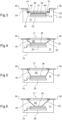
- Figures 3 to 10 show in detail certain steps of the method shown on Figure and carried out by the manufacturing system visible on Figure 1 .
- the curing step 101 illustrated in Figure 3 is followed by the layering step 102 in Figures 4 to 10 , which Figure 10 can be equated also to a further curing step 101.
- the building platform 20 is immersed in the predetermined material 11 at a building position in the tank 10.
- a plurality of layers 3 at least partially hardened are already formed on the building platform 20.
- the transparent plate 21 is here located close to the building platform 20 and acts on a portion 36 of the flexible separation film 22 so that the portion 36 of the flexible separation film 22 is tensed, but not stretched, and a predetermined thickness 60 of the predetermined material 11 remains between the portion 36 of the flexible separation film 22 and the uppermost layer 3 on the building platform 20.
- the curing device (not represented on Figure 3 ) can operate for at least partially hardening the volume of predetermined material 11 in the predetermined thickness 60 between the portion 36 of the flexible separation film 22 and the uppermost layer 3 on the building platform 20 in order to form a novel uppermost layer 3 (visible in Figure 4 ).
- the building platform 20, the transparent plate 21 and the flexible separation film 22 are in first relative positions corresponding to building positions of a layer 3.
- the transparent plate 21 is here wider than the building platform 20 and the layer 3 to be formed so that portions 35 of the flexible separation film 22, interposed between the tensed portion 36 and the ends 31 of flexible separation film 22, are not in contact with the layers 3.
- the portions 35 of the flexible separation film 22 are here located between the frame 30 to which the flexible separation film 22 is mechanically connected by the ends 31 and an outline of the layers 3.
- the portions 35 of the flexible separation film 22 are at least partially tensed thanks to the action of the transparent plate 21 which is here located at a distance, said building distance, of the frame 30.
- the portions 35 of the flexible separation film 22 may have an L-shaped, having a first arm extending from the portion 36 and along the transparent plate 21 and a second arm extending from the first arm to the frame 30.
- the transparent plate 21 comprises vents 40 which are here formed at the location of the portions 35 of the flexible separation film 22.
- the transparent plate 21 can be devoid of such vent because of no-sealing contact between the flexible separation film 22 and the transparent plate 21.
- the transparent plate 21 has been raised up and is located close to the frame 30 to which the flexible separation film 22 is mechanically connected by the ends 31.
- the transparent plate 21 is thus no longer in contact with the flexible separation film 22 and a temporarily space 50 is formed there-between.
- the temporarily space 50 can be filled of a fluid, such as for instance air, thanks to the vents 40.
- the portion 36 of the flexible separation film 22 remains tensed due to the adhesive contact with the cured uppermost layer 3, while the portions 35 of the flexible separation film 22 are loose, or in a loose state.
- the portions 35 are at least partially free of movement between the tensed portion 36 and the respective ends 31.
- the building platform 20 has been raised down towards the bottom of the tank 10 and remotely from the frame 30 to which the flexible separation film 22 is mechanically connected by the ends 31.
- the temporarily space 50 defined between the transparent plate 21 and the flexible separation film 22 has been expanded.
- the portion 36 of the flexible separation film 22 remains tensed due to the adhesive contact with the cured uppermost layer 3 yet, while the portions 35 of the flexible separation film 22 are no longer loose.
- the portions 35 are now tensed, not stretched, between the tensed portion 36 and the respective ends 31.
- the temporarily space 50 defined between the transparent plate 21 and the flexible separation film 22 has been further expanded.
- the flexible separation film 22 begins to peel away from the cured uppermost layer 3.
- the portion 36 which is tensed and in contact with the cured uppermost layer 3 decreases, while the portions 35 extending between the portion 36 and the ends 31 increases and are tensed.
- the temporarily space 50 defined between the transparent plate 21 and the flexible separation film 22 has been further expanded.
- the flexible separation film 22 continues to peel away from the cured uppermost layer 3.
- the flexible separation film 22 has no longer portion 36 which is tensed and in contact with the cured uppermost layer 3.
- the portions 35 thus form a single portion extending between the ends 31, and which is fully loose and free of movement. This single portion 35 is located remote to the uppermost layer 3 on the building platform 20.
- the transparent plate and next the building platform have been moved.
- they can be successively and iteratively moved, the building platform can be moved before transparent plate, or the frame, directly via the tank, can be additionally or alternatively moved rather than the building platform.
- the transparent plate 21 is thus raised down towards the building platform 20 and the latter is thus raised up towards the transparent plate 21, opposite to the bottom of the tank 10.
- the building platform 20 is moved until it reaches a building position in the tank 10, which can be the same or different for the building position shown in Figure 3 .
- the transparent plate 21 has an abutting face 70 which pushes, directly and/or with the aid of the fluid in the temporarily space 50 which decreases, and tenses progressively the flexible separation film 22 until a part of the latter, equated to the portion 36 as defined below, is located in front of the uppermost layer 3, with a predetermined thickness 60 of the predetermined material 11 which remains between the portion 36 of the flexible separation film 22 and the uppermost layer 3 on the building platform 20, and the portions 35 are progressively tensed and extend between the portion 36 and the frame 30.
- the building platform 20, the transparent plate 21 and the flexible separation film 22 are in second relative positions corresponding to layering positions for a novel layer 3.
- the transparent plate 21 is located close to the building platform 20 and acts on the portion 36 of the flexible separation film 22 so that the portion 36 of the flexible separation film 22 is tensed, or in a tense state, but not stretched, and the predetermined thickness 60 of the predetermined material 11 remains between the portion 36 of the flexible separation film 22 and the uppermost layer 3 on the building platform 20.
- the curing device (not represented on Figure 10 ) can operate for at least partially hardening the volume of predetermined material 11 in the predetermined thickness 60 between the portion 36 of the flexible separation film 22 and the uppermost layer 3 on the building platform 20 in order to form another novel uppermost layer 3.
- Figures 3 to 10 illustrate the passage of the manufacturing system from the curing configuration of a layer, to a layering configuration and then to the curing configuration of a successive layer.
- the flexible separation film 22 may have a state in which it is fully loose, at least partially loose and at least partially tensed, and fully tensed. However, the flexible separation film 22 is never stretched.
- the manufacturing system 1 requires leaving a sufficient space between the transparent plate 21 and the building platform 20 in order to allow the flexible separation film 22 to be loose.
- the portions 35 of the flexible separation film 22 may have an L-shaped in the curing configuration.
- the first arm extending from the portion 36 and along the transparent plate 21 corresponds to a first distance, for instance called horizontal distance, between an edge of the transparent plate 21 and the outline of the uppermost layer 3.
- the second arm extending from the first arm to the frame 30 corresponds to a second distance, for instance called vertical distance, between the frame 30 and the edge of the transparent plate 21.
- the first distance remains constant while the second distance increases, from a peeling start position of the flexible separation film 22 shown on Figure 5 to a peeling end position of the flexible separation film 22 shown on Figure 7 .
- the flexible separation film 22 can thus be peeled away from the uppermost layer 3 with a relatively high peeling angle.
- Such a relatively high peeling angle may lead to less stress for both the layer 3 and the flexible separation film 22.
- such a relatively high peeling angle may allow reducing the time of the layering steps, for instance by controlling the speed of the movements of at least one of the building platform 20, transparent plate 21 and flexible separation film 22.
- the velocity of the movement can be higher than when the flexible separation film 22 is tensed.
- the velocity of the movement of the transparent plate 21 and/or building platform 20 can be relatively high, whereas during the peeling as such, shown on Figures 6 to 8 , the velocity of the movement of the transparent plate 21 and/or building platform 20 should be decreased compared to Figures 3 to 5 .
- the velocity of the movement of the transparent plate 21 and/or building platform 20 in order to make the system in the curing configuration by locating the building platform 20 in its building position, approaching the transparent plate 21 and tensing progressively the flexible separation film 22, should be also decreased compared to Figures 3 to 5 and can be rather similar, or lower, or higher, compared to the velocity of the movement during peeling and shown on Figures 6 to 8 .
- the transparent plate may have different shape, including squared, rectangular or others shapes, including a building zone and an edge zone surrounding the building zone.
- the transparent plate is transparent to UV light.
- the transparent plate can be made from glass and/or quartz and/or plastic and/or composite of materials.
- the transparent plate can have a hydrophobic treatment.
- the building zone may have may have a length equal to around 80 mm or higher than 80 mm, and a width equal to around 75 mm, and the edge zone may have, on each longitudinal side of the building zone, a width equal to around 10 mm or lower than 10 mm and, on each transversal side of the building zone, a length equal or higher than the width on each longitudinal side of the building zone, especially if vents are formed on the transparent plate.
- the manufacturing system may further comprises a fluid supply unit configured to supply and suck a fluid between the flexible separation film and the transparent plate.
Landscapes
- Engineering & Computer Science (AREA)
- Chemical & Material Sciences (AREA)
- Materials Engineering (AREA)
- Manufacturing & Machinery (AREA)
- Mechanical Engineering (AREA)
- Physics & Mathematics (AREA)
- Optics & Photonics (AREA)
- Health & Medical Sciences (AREA)
- Ophthalmology & Optometry (AREA)
Claims (15)
- Generatives Fertigungssystem zur schichtweisen generativen Fertigung einer ophthalmischen Vorrichtung, umfassend einen Tank (10), der mit einem Volumen eines polymerisierbaren Materials (11) gefüllt ist, eine Aufbauplattform (20), auf der Schichten (3) aus dem polymerisierbaren Material gebildet werden, eine Aushärtungsvorrichtung (12), die zum zumindest teilweisen Härten der Schichten der zu fertigenden ophthalmischen Vorrichtung ausgelegt ist, eine transparente Platte (21), die sich zwischen der Aufbauplattform (20) und der Aushärtungsvorrichtung (13) befindet, und eine flexible Trennfolie (22), die mechanisch durch Enden (31) mit einem Rahmen (30) verbunden ist und sich zumindest teilweise zwischen der transparenten Platte (21) und der Aufbauplattform (20) befindet, wobei das generative Fertigungssystem (1) so ausgelegt ist, dass die transparente Platte, der Rahmen und die Aufbauplattform relativ zueinander und zu dem Tank (10) zwischen einer ersten relativen Position, die Aufbaupositionen einer Schicht entspricht, in der die transparente Platte gegen die flexible Trennfolie angelegt wird, die sich in einem gespannten Zustand befindet, und einer zweiten relativen Position, die den Schichtpositionen einer Schicht entspricht, in der die transparente Platte relativ zu dem Rahmen verlegt ist und von der flexiblen Trennfolie entfernt ist, die sich zumindest teilweise in einem losen Zustand befindet, bewegbar sind.
- Generatives Fertigungssystem nach Anspruch 1, wobei es eine Bewegungseinheit (25) umfasst, die dazu ausgelegt ist, eines aus der Aufbauplattform (20), der transparenten Platte (21) und dem Rahmen (30) relativ zu den anderen zu bewegen.
- Generatives Fertigungssystem nach Anspruch 2, wobei die Bewegungseinheit (25) abhängig oder unabhängig auf die Aufbauplattform (20) und die transparente Platte (21) und den Rahmen (30), der teilweise die flexible Trennfolie (22) trägt, wirkt.
- Generatives Fertigungssystem nach Anspruch 3, wobei die Bewegungseinheit (25) ausgelegt ist zum: Anheben oder Absenken der Aufbauplattform (20) hin zu oder beabstandet von einem Boden (17) des Tanks (10); und Anheben oder Absenken der transparenten Platte (21) hin zu oder beabstandet von dem Boden (17) des Tanks (10) und somit hin zu oder beabstandet von der Aufbauplattform (20); und Anheben oder Absenken des Rahmens (30) hin zu oder beabstandet von dem Boden (17) des Tanks (10), um mindestens einen Teil der flexiblen Trennfolie (22) in einer Position relativ sowohl zu der Aufbauplattform (20) als auch zu der transparenten Platte (21) zu positionieren; und Anheben oder Absenken des Tanks (10) relativ zu mindestens einem aus der Aufbauplattform (20), der transparenten Platte (21) und dem Rahmen (30).
- Generatives Fertigungssystem nach einem der Ansprüche 1 bis 4, wobei sich die transparente Platte (21) in Aufbaupositionen nahe der Aufbauplattform (20) befindet und auf einen mittleren Abschnitt (36) der flexiblen Trennfolie (22) wirkt, so dass der mittlere Abschnitt (36) der flexiblen Trennfolie (22) gespannt, aber nicht überdehnt ist, und wobei eine vorbestimmte Dicke (60) des polymerisierbaren Materials (11) zwischen dem mittleren Abschnitt (36) der flexiblen Trennfolie (22) und einer obersten Schicht (3) auf der Aufbauplattform (20) verbleibt.
- Generatives Fertigungssystem nach Anspruch 5, wobei die flexible Trennfolie (22) andere Abschnitte (35) umfasst, die zwischen dem mittleren Abschnitt (36) und den Enden (31) der flexiblen Trennfolie (22) angeordnet sind, die von der Schicht (3) entfernt sind und sich zwischen dem Rahmen (30) und einem Umriss der Schicht (3) befinden.
- Generatives Fertigungssystem nach Anspruch 6, wobei die anderen Abschnitte (35) der flexiblen Trennfolien (22) durch die Wirkung der transparenten Platte (21), die sich in einem Abstand von dem Rahmen (30) befindet, zumindest teilweise gespannt sind.
- Generatives Fertigungssystem nach Anspruch 7, wobei die anderen Abschnitte (35) der flexiblen Trennfolie (22) eine L-Form aufweisen, die einen ersten Arm, der sich von dem mittleren Abschnitt (36) und entlang der transparenten Platte (21) erstreckt, und einen zweiten Arm, der sich von dem ersten Arm zu dem Rahmen (30) erstreckt, aufweist.
- Generatives Fertigungssystem nach einem der Ansprüche 1 bis 8, wobei die transparente Platte (21), zumindest in Schichtpositionen, von der Aufbauplattform (20) und der flexiblen Trennfolie (22) entfernt verlegt ist und sich nahe dem Rahmen (30) befindet und ein temporärer Raum (50) zwischen der transparenten Platte (21) und der flexiblen Trennfolie (22) gebildet ist.
- Generatives Fertigungssystem nach Anspruch 9, wobei die flexible Trennfolie (22) einen Mittelabschnitt (36) und andere Abschnitte (35) umfasst, die sich von dem Mittelabschnitt (36) zu den Enden (31) der flexiblen Trennfolie (22) erstrecken, wobei der Mittelabschnitt (36) aufgrund eines Klebekontakts mit einer ausgehärteten obersten Schicht (3) gespannt ist, und die anderen Abschnitte (35) lose sind, so dass die anderen Abschnitte (35) zumindest teilweise frei beweglich zwischen dem gespannten Abschnitt (36) und den jeweiligen Enden (31) sind.
- Generatives Fertigungssystem nach einem der Ansprüche 1 bis 10, wobei die Schichtpositionen Positionen beinhalten, in denen die flexible Trennfolie (22) vollständig von einer ausgehärteten obersten Schicht auf der Aufbauplattform (20) abgelöst ist und entfernt von dieser angeordnet ist und vollständig lose und frei beweglich zwischen den Enden (31) ist.
- Verfahren zur schichtweisen generativen Fertigung einer ophthalmischen Vorrichtung, wobei das Fertigungsverfahren die folgenden Schritte umfasst:- Bereitstellen eines Fertigungssystems (1) mit einem Tank (10), der mit einem Volumen eines polymerisierbaren Materials (11) gefüllt ist, einer Aufbauplattform (20), auf der Schichten (3) aus dem polymerisierbaren Material gebildet werden, einer Aushärtungsvorrichtung (12), die ausgelegt ist zum zumindest teilweisen Härten der Schichten der zu fertigenden ophthalmischen Vorrichtung, einer transparenten Platte (21), die sich zwischen der Aufbauplattform (20) und der Aushärtungsvorrichtung (13) befindet, und einer flexiblen Trennfolie (22), die mechanisch durch Enden (31) mit einem Rahmen (30) verbunden ist und sich zumindest teilweise zwischen der transparenten Platte (21) und der Aufbauplattform (20) befindet;- Steuern des generativen Fertigungssystems (1), so dass die transparente Platte, der Rahmen und die Aufbauplattform relativ zueinander und zum Tank (10) bewegt werden und eine erste Relativposition einnehmen, die den Aufbaupositionen einer Schicht entspricht, in der die transparente Platte gegen die flexible Trennfolie angelegt wird, die sich in einem gespannten Zustand befindet; und- Steuern des generativen Fertigungssystems (1), so dass die transparente Platte, der Rahmen und die Aufbauplattform relativ zueinander und zum Tank (10) bewegt werden und eine zweite Relativposition einnehmen, die den Schichtpositionen einer Schicht entspricht, in der die transparente Platte relativ zum Rahmen bewegt wird und von der flexiblen Trennfolie entfernt ist, die sich zumindest teilweise in einem losen Zustand befindet.
- Verfahren nach Anspruch 12, wobei es die folgenden Schritte umfasst: Bewegen, abhängig oder unabhängig, von einem aus der Aufbauplattform (20), der transparenten Platte (21) und dem Rahmen (30) relativ zu den anderen; und insbesondere: Anheben oder Absenken der Aufbauplattform (20) hin zu oder beabstandet von einem Boden (17) des Tanks (10); und Anheben oder Absenken der transparenten Platte (21) hin zu oder beabstandet von dem Boden (17) des Tanks (10) und somit hin zu oder beabstandet von der Aufbauplattform (20); und Anheben oder Absenken des Rahmens (30) hin zu oder beabstandet von dem Boden (17) des Tanks (10), um mindestens einen Teil der flexiblen Trennfolie (22) in einer Position relativ sowohl zu der Aufbauplattform (20) als auch zu der transparenten Platte (21) zu positionieren; und Anheben oder Absenken des Tanks (10) relativ zu mindestens einem aus der Aufbauplattform (20), der transparenten Platte (21) und dem Rahmen (30).
- Verfahren nach Anspruch 12, wobei, in Aufbaupositionen, die transparente Platte (21) nahe der Aufbauplattform (20) befindlich ist und auf einen mittleren Abschnitt (36) der flexiblen Trennfolie (22) wirkt, so dass der mittlere Abschnitt (36) der flexiblen Trennfolie (22) gespannt, aber nicht überdehnt wird, und wobei eine vorbestimmte Dicke (60) des polymerisierbaren Materials (11) zwischen dem mittleren Abschnitt (36) der flexiblen Trennfolie (22) und einer obersten Schicht (3) auf der Aufbauplattform (20) verbleibt, wobei die flexible Trennfolie (22) andere Abschnitte (35) umfasst, die zwischen dem mittleren Abschnitt (36) und den Enden (31) der flexiblen Trennfolie (22) angeordnet sind, die entfernt von der Schicht (3) sind und sich zwischen dem Rahmen (30) und einem Umriss der Schicht (3) befinden, wobei die anderen Abschnitte (35) der flexiblen Trennfolien (22) durch die Wirkung der transparenten Platte (21), die sich im Abstand zum Rahmen (30) befindet, zumindest teilweise gespannt sind.
- Verfahren nach einem der Ansprüche 13 und 14, wobei, zumindest in Schichtpositionen, die transparente Platte (21) beabstandet von der Aufbauplattform (20) und der flexiblen Trennfolie (22) bewegt wird und nahe dem Rahmen (30) verlegt ist, und ein temporärer Raum (50) zwischen der transparenten Platte (21) und der flexiblen Trennfolie (22) gebildet wird, wobei die flexible Trennfolie (22) einen mittleren Abschnitt (36) und andere Abschnitte (35), die sich von dem mittleren Abschnitt (36) zu den Enden (31) der flexiblen Trennfolie (22) erstrecken, umfasst, wobei der mittlere Abschnitt (36) aufgrund eines Klebekontakts mit einer ausgehärteten obersten Schicht (3) gespannt wird, und wobei die anderen Abschnitte (35) lose sind, so dass die anderen Abschnitte (35) zumindest teilweise frei beweglich zwischen dem gespannten Abschnitt (36) und den jeweiligen Enden (31) sind; und wobei die Schichtpositionen Positionen beinhalten, in denen die flexible Trennfolie (22) vollständig von einer ausgehärteten obersten Schicht auf der Aufbauplattform (20) abgelöst und von dieser entfernt angeordnet ist, und vollständig lose und frei beweglich zwischen den Enden (31) ist.
Priority Applications (5)
| Application Number | Priority Date | Filing Date | Title |
|---|---|---|---|
| ES21306758T ES3033773T3 (en) | 2021-12-13 | 2021-12-13 | Manufacturing system configured to carry out a method for additively manufacturing an ophthalmic device and such a method |
| EP21306758.0A EP4194178B1 (de) | 2021-12-13 | 2021-12-13 | Zur durchführung eines verfahrens zur generativen fertigung einer ophthalmischen vorrichtung konfiguriertes fertigungssystem und solch ein verfahren |
| CN202280079148.1A CN118317860A (zh) | 2021-12-13 | 2022-12-13 | 实施用于增材制造眼科装置的方法的制造系统及这种方法 |
| US18/718,685 US12600089B2 (en) | 2021-12-13 | 2022-12-13 | Manufacturing system configured to carry out a method for additively manufacturing an ophthalmic device and such a method |
| PCT/EP2022/085505 WO2023110805A1 (en) | 2021-12-13 | 2022-12-13 | Manufacturing system configured to carry out a method for additively manufacturing an ophthalmic device and such a method |
Applications Claiming Priority (1)
| Application Number | Priority Date | Filing Date | Title |
|---|---|---|---|
| EP21306758.0A EP4194178B1 (de) | 2021-12-13 | 2021-12-13 | Zur durchführung eines verfahrens zur generativen fertigung einer ophthalmischen vorrichtung konfiguriertes fertigungssystem und solch ein verfahren |
Publications (3)
| Publication Number | Publication Date |
|---|---|
| EP4194178A1 EP4194178A1 (de) | 2023-06-14 |
| EP4194178B1 true EP4194178B1 (de) | 2025-04-09 |
| EP4194178C0 EP4194178C0 (de) | 2025-04-09 |
Family
ID=79024622
Family Applications (1)
| Application Number | Title | Priority Date | Filing Date |
|---|---|---|---|
| EP21306758.0A Active EP4194178B1 (de) | 2021-12-13 | 2021-12-13 | Zur durchführung eines verfahrens zur generativen fertigung einer ophthalmischen vorrichtung konfiguriertes fertigungssystem und solch ein verfahren |
Country Status (5)
| Country | Link |
|---|---|
| US (1) | US12600089B2 (de) |
| EP (1) | EP4194178B1 (de) |
| CN (1) | CN118317860A (de) |
| ES (1) | ES3033773T3 (de) |
| WO (1) | WO2023110805A1 (de) |
Family Cites Families (5)
| Publication number | Priority date | Publication date | Assignee | Title |
|---|---|---|---|---|
| DE10119817A1 (de) | 2001-04-23 | 2002-10-24 | Envision Technologies Gmbh | Vorrichtung und Verfahren für die zerstörungsfreie Trennung ausgehärteter Materialschichten von einer planen Bauebene |
| DE102012011610A1 (de) * | 2012-06-12 | 2012-11-29 | Daimler Ag | Vorrichtung und Verfahren zur Herstellung eines Bauteils |
| GB201501382D0 (en) * | 2015-01-28 | 2015-03-11 | Structo Pte Ltd | Additive manufacturing device with release mechanism |
| WO2018170544A1 (en) | 2017-03-20 | 2018-09-27 | Justin Elsey | Apparatus and method for making a stereolithographic object |
| US11104075B2 (en) * | 2018-11-01 | 2021-08-31 | Stratasys, Inc. | System for window separation in an additive manufacturing process |
-
2021
- 2021-12-13 ES ES21306758T patent/ES3033773T3/es active Active
- 2021-12-13 EP EP21306758.0A patent/EP4194178B1/de active Active
-
2022
- 2022-12-13 CN CN202280079148.1A patent/CN118317860A/zh active Pending
- 2022-12-13 WO PCT/EP2022/085505 patent/WO2023110805A1/en not_active Ceased
- 2022-12-13 US US18/718,685 patent/US12600089B2/en active Active
Also Published As
| Publication number | Publication date |
|---|---|
| ES3033773T3 (en) | 2025-08-07 |
| EP4194178A1 (de) | 2023-06-14 |
| EP4194178C0 (de) | 2025-04-09 |
| WO2023110805A1 (en) | 2023-06-22 |
| US12600089B2 (en) | 2026-04-14 |
| US20250042087A1 (en) | 2025-02-06 |
| CN118317860A (zh) | 2024-07-09 |
Similar Documents
| Publication | Publication Date | Title |
|---|---|---|
| US12468221B2 (en) | Imprint apparatus for forming a pattern of an imprint material on a substrate-side pattern region of a substrate by using a mold, and related device manufacturing methods | |
| US12275170B2 (en) | Device for making an object and a method for making an object | |
| JP7353449B2 (ja) | ポリマー製品を成型する方法および装置 | |
| US7438846B2 (en) | Apparatus and method for the non-destructive separation of hardened material layers from a flat construction plane | |
| US20170297261A1 (en) | Method and system for producing a three-dimensional object | |
| EP3023230A2 (de) | Trennfolie/-schicht, system und verfahren zur verwendung derselben bei der zusatzstoffherstellung | |
| JPH06246838A (ja) | 光造形装置 | |
| KR20160008307A (ko) | 광학투명레진을 이용한 디스플레이 모듈 제조방법 | |
| KR101673580B1 (ko) | 마이크로 디바이스의 전사장치, 마이크로 디바이스의 전사방법, 및 그 전사장치의 제조방법 | |
| KR102050428B1 (ko) | 3d프린터의 소재트레이 | |
| JP2007536130A (ja) | 構成面からの硬化材料層の分離が改良された、3次元物体を製造するための方法 | |
| US20220193999A1 (en) | Apparatus and method for making a stereolithographic object | |
| EP4194178B1 (de) | Zur durchführung eines verfahrens zur generativen fertigung einer ophthalmischen vorrichtung konfiguriertes fertigungssystem und solch ein verfahren | |
| CN102481734A (zh) | 具有规整结构化表面的物体的生产方法 | |
| JP6995530B2 (ja) | 型を用いて基板上の組成物を成形する成形装置及び物品の製造方法 | |
| US20260102963A1 (en) | Method for additively manufacturing an ophthalmic device and manufacturing system configured to carry out such a method | |
| KR102296436B1 (ko) | 레이어의 객체 모양을 통해 틸팅 속도를 제어하는 방법 | |
| EP4410519B1 (de) | Stereolithographievorrichtung und verfahren zur herstellung eines 3d-gedruckten objekts | |
| CN118849447A (zh) | Pet反射膜向特大型碳塑球面反射镜整体转移装置及其方法 |
Legal Events
| Date | Code | Title | Description |
|---|---|---|---|
| PUAI | Public reference made under article 153(3) epc to a published international application that has entered the european phase |
Free format text: ORIGINAL CODE: 0009012 |
|
| STAA | Information on the status of an ep patent application or granted ep patent |
Free format text: STATUS: THE APPLICATION HAS BEEN PUBLISHED |
|
| AK | Designated contracting states |
Kind code of ref document: A1 Designated state(s): AL AT BE BG CH CY CZ DE DK EE ES FI FR GB GR HR HU IE IS IT LI LT LU LV MC MK MT NL NO PL PT RO RS SE SI SK SM TR |
|
| STAA | Information on the status of an ep patent application or granted ep patent |
Free format text: STATUS: REQUEST FOR EXAMINATION WAS MADE |
|
| 17P | Request for examination filed |
Effective date: 20230919 |
|
| RBV | Designated contracting states (corrected) |
Designated state(s): AL AT BE BG CH CY CZ DE DK EE ES FI FR GB GR HR HU IE IS IT LI LT LU LV MC MK MT NL NO PL PT RO RS SE SI SK SM TR |
|
| STAA | Information on the status of an ep patent application or granted ep patent |
Free format text: STATUS: EXAMINATION IS IN PROGRESS |
|
| 17Q | First examination report despatched |
Effective date: 20240221 |
|
| GRAP | Despatch of communication of intention to grant a patent |
Free format text: ORIGINAL CODE: EPIDOSNIGR1 |
|
| STAA | Information on the status of an ep patent application or granted ep patent |
Free format text: STATUS: GRANT OF PATENT IS INTENDED |
|
| INTG | Intention to grant announced |
Effective date: 20241107 |
|
| GRAS | Grant fee paid |
Free format text: ORIGINAL CODE: EPIDOSNIGR3 |
|
| GRAA | (expected) grant |
Free format text: ORIGINAL CODE: 0009210 |
|
| STAA | Information on the status of an ep patent application or granted ep patent |
Free format text: STATUS: THE PATENT HAS BEEN GRANTED |
|
| AK | Designated contracting states |
Kind code of ref document: B1 Designated state(s): AL AT BE BG CH CY CZ DE DK EE ES FI FR GB GR HR HU IE IS IT LI LT LU LV MC MK MT NL NO PL PT RO RS SE SI SK SM TR |
|
| REG | Reference to a national code |
Ref country code: GB Ref legal event code: FG4D |
|
| REG | Reference to a national code |
Ref country code: CH Ref legal event code: EP |
|
| REG | Reference to a national code |
Ref country code: DE Ref legal event code: R096 Ref document number: 602021028848 Country of ref document: DE |
|
| REG | Reference to a national code |
Ref country code: IE Ref legal event code: FG4D |
|
| U01 | Request for unitary effect filed |
Effective date: 20250502 |
|
| U07 | Unitary effect registered |
Designated state(s): AT BE BG DE DK EE FI FR IT LT LU LV MT NL PT RO SE SI Effective date: 20250508 |
|
| REG | Reference to a national code |
Ref country code: ES Ref legal event code: FG2A Ref document number: 3033773 Country of ref document: ES Kind code of ref document: T3 Effective date: 20250807 |
|
| PG25 | Lapsed in a contracting state [announced via postgrant information from national office to epo] |
Ref country code: GR Free format text: LAPSE BECAUSE OF FAILURE TO SUBMIT A TRANSLATION OF THE DESCRIPTION OR TO PAY THE FEE WITHIN THE PRESCRIBED TIME-LIMIT Effective date: 20250710 Ref country code: NO Free format text: LAPSE BECAUSE OF FAILURE TO SUBMIT A TRANSLATION OF THE DESCRIPTION OR TO PAY THE FEE WITHIN THE PRESCRIBED TIME-LIMIT Effective date: 20250709 |
|
| PG25 | Lapsed in a contracting state [announced via postgrant information from national office to epo] |
Ref country code: PL Free format text: LAPSE BECAUSE OF FAILURE TO SUBMIT A TRANSLATION OF THE DESCRIPTION OR TO PAY THE FEE WITHIN THE PRESCRIBED TIME-LIMIT Effective date: 20250409 |
|
| PG25 | Lapsed in a contracting state [announced via postgrant information from national office to epo] |
Ref country code: HR Free format text: LAPSE BECAUSE OF FAILURE TO SUBMIT A TRANSLATION OF THE DESCRIPTION OR TO PAY THE FEE WITHIN THE PRESCRIBED TIME-LIMIT Effective date: 20250409 |
|
| PG25 | Lapsed in a contracting state [announced via postgrant information from national office to epo] |
Ref country code: RS Free format text: LAPSE BECAUSE OF FAILURE TO SUBMIT A TRANSLATION OF THE DESCRIPTION OR TO PAY THE FEE WITHIN THE PRESCRIBED TIME-LIMIT Effective date: 20250709 |
|
| PG25 | Lapsed in a contracting state [announced via postgrant information from national office to epo] |
Ref country code: IS Free format text: LAPSE BECAUSE OF FAILURE TO SUBMIT A TRANSLATION OF THE DESCRIPTION OR TO PAY THE FEE WITHIN THE PRESCRIBED TIME-LIMIT Effective date: 20250809 |
|
| PGFP | Annual fee paid to national office [announced via postgrant information from national office to epo] |
Ref country code: GB Payment date: 20251229 Year of fee payment: 5 |
|
| PG25 | Lapsed in a contracting state [announced via postgrant information from national office to epo] |
Ref country code: SM Free format text: LAPSE BECAUSE OF FAILURE TO SUBMIT A TRANSLATION OF THE DESCRIPTION OR TO PAY THE FEE WITHIN THE PRESCRIBED TIME-LIMIT Effective date: 20250409 |
|
| PG25 | Lapsed in a contracting state [announced via postgrant information from national office to epo] |
Ref country code: CZ Free format text: LAPSE BECAUSE OF FAILURE TO SUBMIT A TRANSLATION OF THE DESCRIPTION OR TO PAY THE FEE WITHIN THE PRESCRIBED TIME-LIMIT Effective date: 20250409 |
|
| PG25 | Lapsed in a contracting state [announced via postgrant information from national office to epo] |
Ref country code: SK Free format text: LAPSE BECAUSE OF FAILURE TO SUBMIT A TRANSLATION OF THE DESCRIPTION OR TO PAY THE FEE WITHIN THE PRESCRIBED TIME-LIMIT Effective date: 20250409 |
|
| U20 | Renewal fee for the european patent with unitary effect paid |
Year of fee payment: 5 Effective date: 20251229 |
|
| PLBE | No opposition filed within time limit |
Free format text: ORIGINAL CODE: 0009261 |
|
| STAA | Information on the status of an ep patent application or granted ep patent |
Free format text: STATUS: NO OPPOSITION FILED WITHIN TIME LIMIT |
|
| REG | Reference to a national code |
Ref country code: CH Ref legal event code: L10 Free format text: ST27 STATUS EVENT CODE: U-0-0-L10-L00 (AS PROVIDED BY THE NATIONAL OFFICE) Effective date: 20260218 |
|
| U1N | Appointed representative for the unitary patent procedure changed after the registration of the unitary effect |
Representative=s name: KILBURN & STRODE LLP; GB |
|
| 26N | No opposition filed |
Effective date: 20260112 |
|
| PGFP | Annual fee paid to national office [announced via postgrant information from national office to epo] |
Ref country code: ES Payment date: 20260102 Year of fee payment: 5 |