EP4194151A1 - Storage system and container for same - Google Patents
Storage system and container for same Download PDFInfo
- Publication number
- EP4194151A1 EP4194151A1 EP22184245.3A EP22184245A EP4194151A1 EP 4194151 A1 EP4194151 A1 EP 4194151A1 EP 22184245 A EP22184245 A EP 22184245A EP 4194151 A1 EP4194151 A1 EP 4194151A1
- Authority
- EP
- European Patent Office
- Prior art keywords
- mounting portion
- container
- partial mounting
- container portion
- hinge
- Prior art date
- Legal status (The legal status is an assumption and is not a legal conclusion. Google has not performed a legal analysis and makes no representation as to the accuracy of the status listed.)
- Pending
Links
Images


Classifications
-
- B—PERFORMING OPERATIONS; TRANSPORTING
- B25—HAND TOOLS; PORTABLE POWER-DRIVEN TOOLS; MANIPULATORS
- B25H—WORKSHOP EQUIPMENT, e.g. FOR MARKING-OUT WORK; STORAGE MEANS FOR WORKSHOPS
- B25H3/00—Storage means or arrangements for workshops facilitating access to, or handling of, work tools or instruments
- B25H3/02—Boxes
- B25H3/021—Boxes comprising a number of connected storage elements
-
- B—PERFORMING OPERATIONS; TRANSPORTING
- B25—HAND TOOLS; PORTABLE POWER-DRIVEN TOOLS; MANIPULATORS
- B25H—WORKSHOP EQUIPMENT, e.g. FOR MARKING-OUT WORK; STORAGE MEANS FOR WORKSHOPS
- B25H3/00—Storage means or arrangements for workshops facilitating access to, or handling of, work tools or instruments
- B25H3/02—Boxes
-
- B—PERFORMING OPERATIONS; TRANSPORTING
- B65—CONVEYING; PACKING; STORING; HANDLING THIN OR FILAMENTARY MATERIAL
- B65D—CONTAINERS FOR STORAGE OR TRANSPORT OF ARTICLES OR MATERIALS, e.g. BAGS, BARRELS, BOTTLES, BOXES, CANS, CARTONS, CRATES, DRUMS, JARS, TANKS, HOPPERS, FORWARDING CONTAINERS; ACCESSORIES, CLOSURES, OR FITTINGS THEREFOR; PACKAGING ELEMENTS; PACKAGES
- B65D25/00—Details of other kinds or types of rigid or semi-rigid containers
- B65D25/20—External fittings
- B65D25/22—External fittings for facilitating lifting or suspending of containers
-
- B—PERFORMING OPERATIONS; TRANSPORTING
- B25—HAND TOOLS; PORTABLE POWER-DRIVEN TOOLS; MANIPULATORS
- B25H—WORKSHOP EQUIPMENT, e.g. FOR MARKING-OUT WORK; STORAGE MEANS FOR WORKSHOPS
- B25H1/00—Work benches; Portable stands or supports for positioning portable tools or work to be operated on thereby
- B25H1/02—Work benches; Portable stands or supports for positioning portable tools or work to be operated on thereby of table type
-
- B—PERFORMING OPERATIONS; TRANSPORTING
- B25—HAND TOOLS; PORTABLE POWER-DRIVEN TOOLS; MANIPULATORS
- B25H—WORKSHOP EQUIPMENT, e.g. FOR MARKING-OUT WORK; STORAGE MEANS FOR WORKSHOPS
- B25H3/00—Storage means or arrangements for workshops facilitating access to, or handling of, work tools or instruments
- B25H3/04—Racks
-
- B—PERFORMING OPERATIONS; TRANSPORTING
- B25—HAND TOOLS; PORTABLE POWER-DRIVEN TOOLS; MANIPULATORS
- B25H—WORKSHOP EQUIPMENT, e.g. FOR MARKING-OUT WORK; STORAGE MEANS FOR WORKSHOPS
- B25H3/00—Storage means or arrangements for workshops facilitating access to, or handling of, work tools or instruments
- B25H3/06—Trays
-
- B—PERFORMING OPERATIONS; TRANSPORTING
- B65—CONVEYING; PACKING; STORING; HANDLING THIN OR FILAMENTARY MATERIAL
- B65D—CONTAINERS FOR STORAGE OR TRANSPORT OF ARTICLES OR MATERIALS, e.g. BAGS, BARRELS, BOTTLES, BOXES, CANS, CARTONS, CRATES, DRUMS, JARS, TANKS, HOPPERS, FORWARDING CONTAINERS; ACCESSORIES, CLOSURES, OR FITTINGS THEREFOR; PACKAGING ELEMENTS; PACKAGES
- B65D43/00—Lids or covers for rigid or semi-rigid containers
- B65D43/14—Non-removable lids or covers
- B65D43/16—Non-removable lids or covers hinged for upward or downward movement
-
- B—PERFORMING OPERATIONS; TRANSPORTING
- B65—CONVEYING; PACKING; STORING; HANDLING THIN OR FILAMENTARY MATERIAL
- B65D—CONTAINERS FOR STORAGE OR TRANSPORT OF ARTICLES OR MATERIALS, e.g. BAGS, BARRELS, BOTTLES, BOXES, CANS, CARTONS, CRATES, DRUMS, JARS, TANKS, HOPPERS, FORWARDING CONTAINERS; ACCESSORIES, CLOSURES, OR FITTINGS THEREFOR; PACKAGING ELEMENTS; PACKAGES
- B65D43/00—Lids or covers for rigid or semi-rigid containers
- B65D43/14—Non-removable lids or covers
- B65D43/22—Devices for holding in closed position, e.g. clips
Definitions
- the present disclosure relates to storage systems, and more particularly to wallmounted storage containers for tool accessories and the like.
- Hand tools, power tools, and associated accessories such as batteries, tool bits, sockets, accessories, fasteners, and the like, may be moved frequently between a storage space and a work space.
- One aspect of accessibility is a user's ability to quickly store an object and remove the object from storage.
- a storage container in one independent aspect, includes a first container portion including a first side; a second container portion including a second side, and a support feature configured to engage a wall support system.
- the second side is pivotably coupled to the first side of the first container portion by a hinge.
- the second container portion and the first container portion are pivotably movable between a closed position and an open position.
- the support feature includes a first partial mounting portion and a second partial mounting portion.
- the first partial mounting portion is positioned on the first container portion, and the second partial mounting portion is supported for movement relative to the first partial mounting portion.
- the second partial mounting portion is movable between a stowed position and an extended portion.
- the first partial mounting portion and the second partial mounting portion cooperate to provide a mounting interface configured to engage a support member while the second partial mounting portion is in the extended position.
- a storage system in another independent aspect, includes a panel secured to a support surface and a storage container removably supported on the panel.
- the panel includes a plurality of cleats spaced apart from one another.
- the storage container includes a first container portion including a first side, a second container portion including a second side, and a support feature engageable with the cleats.
- the second side is pivotably coupled to the first side of the first container portion by a hinge.
- the second container portion and the first container portion are pivotably movable between a closed position and an open position.
- the support feature includes a first partial mounting portion and a second partial mounting portion. The first partial mounting portion is positioned on the first container portion.
- the second partial mounting portion is supported for movement relative to the first partial mounting portion, and the second partial mounting portion is movable between a stowed position and an extended portion.
- the first partial mounting portion and the second partial mounting portion cooperate to provide a mounting interface to engage at least one of the cleats while the second partial mounting portion is in the extended position.
- a storage container includes: a first container portion; a second container portion; a hinge coupling a first side of the first container portion and a second side of the second container portion for pivoting movement about a pivot axis, a latch releasably securing the first container portion and the second container portion in the closed position, a first partial mounting portion positioned on the first container portion, and a second partial mounting portion supported on the hinge for pivoting movement relative to the first partial mounting portion and the second container portion.
- the first container portion and the second container portion are pivotably movable between a closed position and an open position.
- the second partial mounting portion is movable between a stowed position and an extended position.
- the first partial mounting portion and the second partial mounting portion cooperate to form a mounting interface while the first container portion and the second container portion are in the closed position and the second partial mounting portion is in the extended position.
- the mounting interface is configured to engage the wall support system.
- connection and “coupled” are not restricted to physical or mechanical connections or couplings, whether direct or indirect. Terms of degree, such as “substantially,” “about,” “approximately,” etc. are understood by those of ordinary skill to refer to reasonable ranges outside of the given value, for example, general tolerances associated with manufacturing, assembly, and use of the described embodiments.
- FIGS. 1-3 illustrate a storage system 10 including a storage container 100 ( FIG. 1 ) that is engageable with and supported by a support panel 200 ( FIG. 2 ).
- the panel 200 supports two containers 100, but it is understood that fewer or more containers could be supported on the panel 200.
- Each container 100 engages the panel 200 independently of the other containers 100, and can be removed from the panel 200 independently of the other containers 100.
- the panel 200 includes a plurality of cleats 204 which are generally aligned and spaced apart from one another.
- the cleats 204 protrude from the surface of the panel 200.
- the panel 200 may be secured to a support surface or wall (e.g., by one or more fasteners).
- the panel 200 is shown as a rail having a single row of six cleats 204a-204f aligned with one another in a direction parallel to a longitudinal axis 208 of the rail 200; in other embodiments, the panel may have fewer or more cleats, and/or may have multiple rows of cleats.
- multiple panels and/or rails may be secured to the support surface adjacent the illustrated rail 200.
- the rail 200 includes extension features 226 positioned on each edge, and adjacent rails have complementary extension features to facilitate alignment and interconnection between adjacent rails.
- the cleats 204 have a generally octagonal shape. Stated another way, in the illustrated embodiment each cleat 204 includes four inclined edges 220 that are oriented at an acute angle relative to the longitudinal axis 208 of the rail 200 and that substantially form a diamond shape. In other embodiments, the cleat 204 may have a profile that is a different shape (e.g., hexagonal, rectangular, an irregular polygonal shape, a curvilinear shape), and/or the cleat 204 may have a different number of inclined edges. Each of the cleats 204 is separated from an adjacent cleat by a gap or space 216.
- partial gaps are located between the outermost cleats and the associated end of the rail 200, and the outermost cleats 204 will be spaced apart from a cleat of an adjacent panel or rail by the same distance as adjacent cleats 204 of the same rail 200.
- the storage container 100 is supported within a gap 216 between two adjacent cleats 204.
- Other attachments and/or objects may be located within the gaps 216 to engage one or more cleats 204.
- the container 100 includes a first container portion 104 and a second container portion 108 that are joined together by a hinge 112.
- the first container portion 104 and the second container portion 108 are substantially similar to one another, and the container is a clamshell-type.
- the container portions may have different shapes-for example, one portion may provide an internal compartment for storage, and another portion may provide a lid for covering the internal compartment.
- the hinge 112 is positioned adjacent a first side (e.g., a rear side 116) of the first container portion 104 and a first side (e.g., a rear side 120) of the second container portion 108, and the container portions 104, 108 are pivotable relative to one another about a hinge 112 between a closed portion and an open position.
- a second side e.g., a front side 134 - FIG. 3
- the first container portion 104 and the second container portion 108 can be releasably secured to one another in the closed position by a latch 140.
- the container 100 may include a handle.
- the first container portion 104 includes first lugs 142 and the second container portion 108 includes second lugs 144 aligned with the first lugs 142.
- the hinge 112 includes a pin 146 extending through the first lugs 142 and the second lugs 144 along a pivot axis 148 about which the container portions 104, 106 pivot relative to one another.
- the first container portion 104 and the second container portion 108 may be coupled to one another in a different manner.
- the container 100 also includes a support feature 152 for coupling the container 100 to the support panel 200.
- the support feature 152 includes a first partial mounting portion 156 and a second partial mounting portion 160.
- the first partial mounting portion 156 is positioned on one side of the first container portion 104 (e.g., the rear side 116). In the illustrated embodiment, the first partial mounting portion 156 is formed integrally with the rear side 116. In other embodiments, the first partial mounting portion 156 may be coupled to the rear side 116 in a different manner.
- the second partial mounting portion 160 is supported for pivoting movement relative to the first partial mounting portion 156 between a stowed position ( FIG. 4 ) and an extended position ( FIG. 7 ). In the illustrated embodiment, the second partial mounting portion 160 is supported for pivoting movement on the hinge pin 146.
- the first partial mounting portion 156 includes a first flange 162
- the second partial mounting portion 160 includes a collar 164 and a second flange 168 protruding from the collar 164.
- the collar 164 is coupled to and movable relative to the hinge pin 146.
- the collar 164 is both pivotable about the pivot axis 148 and is also slidable in a direction parallel to the pivot axis 148. While in the stowed position (shown in FIG. 4 ), the second partial mounting portion 160 is positioned adjacent and coupled to the first partial mounting portion 156 ( FIG. 6 ).
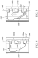
- the second partial mounting portion 160 slides a first distance D1 in a direction parallel to the pivot axis 148, as shown in FIG. 5 .
- the second partial mounting portion 160 is then rotated about the pivot axis 148, as shown in FIG. 6 .
- the second partial mounting portion 160 is rotated so that the second flange 168 is diametrically opposite the first partial mounting portion 156.
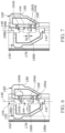
- the second partial mounting portion 160 then slides a second distance D2 in a direction parallel to the pivot axis 148 to the extended position.
- the first partial mounting portion 156 includes a first edge 176 oriented at an acute angle relative to the pivot axis 148.
- the second partial mounting portion 160 includes a second edge 180 oriented at an acute angle relative to the pivot axis 148.
- the first edge 176 and the second edge 180 are positioned at the same location along the pivot axis 148.
- the first edge 176 and the second edge 180 are positioned to engage the angled edges of adjacent cleats 204 ( FIG. 2 ) of the panel 200 when the support feature 152 is positioned in the gap 216 between the cleats 204.
- the container 100 can be coupled to the panel 200 by aligning the support feature 152 between two cleats 204 and moving the container 100 downwardly until the first edge 176 and the second edge 180 engage the cleats 204.
- the collar 164 includes two portions 164a, 164b, and each side of the collar portions 164a, 164b includes protrusions (e.g., castellations 184a, 184b) that extend parallel to the pivot axis 148.
- at least one of the lugs 142, 144 includes slots (e.g., castellations 188a, 188b) that are complementary with the collar castellations 184a, 184b. In the stowed position, one of the collar castellations 184a engages a first one of the lug castellations 188a.
- other collar castellations e.g., castellations 184b protruding from an opposite side of the collar portions 164a, 164b
- the depth of the castellations 184a, 188a may correspond to the first distance D1
- the depth of the castellations 184b, 188b may correspond to the second distance D2.
- the engagement of the collar castellations 184a, 184b and lug castellations 188a, 188b inhibits undesired rotation, requiring a user to translate the second partial mounting portion 160 along the axis 148 before rotating it.
- a detent may be provided to inhibit undesired translational movement of the second partial mounting portion 160 along the axis 148.
Landscapes
- Engineering & Computer Science (AREA)
- Mechanical Engineering (AREA)
- Details Of Rigid Or Semi-Rigid Containers (AREA)
Abstract
Description
- The present application claims the benefit of co-pending
U.S. Provisional Patent Application No. 63/220,801, filed July 12, 2021 U.S. Provisional Patent Application No. 63/302,934, filed January 25, 2022 - The present disclosure relates to storage systems, and more particularly to wallmounted storage containers for tool accessories and the like.
- Hand tools, power tools, and associated accessories such as batteries, tool bits, sockets, accessories, fasteners, and the like, may be moved frequently between a storage space and a work space. One aspect of accessibility is a user's ability to quickly store an object and remove the object from storage.
- In one independent aspect, a storage container includes a first container portion including a first side; a second container portion including a second side, and a support feature configured to engage a wall support system. The second side is pivotably coupled to the first side of the first container portion by a hinge. The second container portion and the first container portion are pivotably movable between a closed position and an open position. The support feature includes a first partial mounting portion and a second partial mounting portion. The first partial mounting portion is positioned on the first container portion, and the second partial mounting portion is supported for movement relative to the first partial mounting portion. The second partial mounting portion is movable between a stowed position and an extended portion. The first partial mounting portion and the second partial mounting portion cooperate to provide a mounting interface configured to engage a support member while the second partial mounting portion is in the extended position.
- In another independent aspect, a storage system includes a panel secured to a support surface and a storage container removably supported on the panel. The panel includes a plurality of cleats spaced apart from one another. The storage container includes a first container portion including a first side, a second container portion including a second side, and a support feature engageable with the cleats. The second side is pivotably coupled to the first side of the first container portion by a hinge. The second container portion and the first container portion are pivotably movable between a closed position and an open position. The support feature includes a first partial mounting portion and a second partial mounting portion. The first partial mounting portion is positioned on the first container portion. The second partial mounting portion is supported for movement relative to the first partial mounting portion, and the second partial mounting portion is movable between a stowed position and an extended portion. The first partial mounting portion and the second partial mounting portion cooperate to provide a mounting interface to engage at least one of the cleats while the second partial mounting portion is in the extended position.
- In yet another independent aspect, a storage container includes: a first container portion; a second container portion; a hinge coupling a first side of the first container portion and a second side of the second container portion for pivoting movement about a pivot axis, a latch releasably securing the first container portion and the second container portion in the closed position, a first partial mounting portion positioned on the first container portion, and a second partial mounting portion supported on the hinge for pivoting movement relative to the first partial mounting portion and the second container portion. The first container portion and the second container portion are pivotably movable between a closed position and an open position. The second partial mounting portion is movable between a stowed position and an extended position. The first partial mounting portion and the second partial mounting portion cooperate to form a mounting interface while the first container portion and the second container portion are in the closed position and the second partial mounting portion is in the extended position. The mounting interface is configured to engage the wall support system.
- Other aspects of the disclosure will become apparent by consideration of the detailed description and accompanying drawings.
-
-
FIG. 1 is a perspective view of a storage container. -
FIG. 2 is a perspective view of a support panel. -
FIG. 3 is a perspective view of a storage system including the support panel ofFIG. 2 supporting storage containers. -
FIG. 4 is a side view of the storage container ofFIG. 1 , with a coupling feature in a stowed position. -
FIG. 5 is a side view of the storage container ofFIG. 1 , with a coupling feature in a second position. -
FIG. 6 is a side view of the storage container ofFIG. 1 , with a coupling feature in a third position. -
FIG. 7 is a side view of the storage container ofFIG. 1 , with a coupling feature in an extended position. - Before any embodiments of the disclosure are explained in detail, it is to be understood that the disclosure is not limited in its application to the details of construction and the arrangement of components set forth in the following description or illustrated in the following drawings. The disclosure is capable of other embodiments and of being practiced or of being carried out in various ways. Also, it is to be understood that the phraseology and terminology used herein is for the purpose of description and should not be regarded as limited. The use of "including," "comprising" or "having" and variations thereof herein is meant to encompass the items listed thereafter and equivalents thereof as well as additional items. The terms "mounted," "connected" and "coupled" are used broadly and encompass both direct and indirect mounting, connecting and coupling. Further, "connected" and "coupled" are not restricted to physical or mechanical connections or couplings, whether direct or indirect. Terms of degree, such as "substantially," "about," "approximately," etc. are understood by those of ordinary skill to refer to reasonable ranges outside of the given value, for example, general tolerances associated with manufacturing, assembly, and use of the described embodiments.
-
FIGS. 1-3 illustrate astorage system 10 including a storage container 100 (FIG. 1 ) that is engageable with and supported by a support panel 200 (FIG. 2 ). In the illustrated embodiment, thepanel 200 supports twocontainers 100, but it is understood that fewer or more containers could be supported on thepanel 200. Eachcontainer 100 engages thepanel 200 independently of theother containers 100, and can be removed from thepanel 200 independently of theother containers 100. - As shown in
FIG. 2 , thepanel 200 includes a plurality ofcleats 204 which are generally aligned and spaced apart from one another. Thecleats 204 protrude from the surface of thepanel 200. Thepanel 200 may be secured to a support surface or wall (e.g., by one or more fasteners). In the illustrated embodiment, thepanel 200 is shown as a rail having a single row of sixcleats 204a-204f aligned with one another in a direction parallel to alongitudinal axis 208 of therail 200; in other embodiments, the panel may have fewer or more cleats, and/or may have multiple rows of cleats. Additionally (or alternatively), multiple panels and/or rails may be secured to the support surface adjacent the illustratedrail 200. In the illustrated embodiment, therail 200 includesextension features 226 positioned on each edge, and adjacent rails have complementary extension features to facilitate alignment and interconnection between adjacent rails. - In the illustrated embodiment, the
cleats 204 have a generally octagonal shape. Stated another way, in the illustrated embodiment eachcleat 204 includes fourinclined edges 220 that are oriented at an acute angle relative to thelongitudinal axis 208 of therail 200 and that substantially form a diamond shape. In other embodiments, thecleat 204 may have a profile that is a different shape (e.g., hexagonal, rectangular, an irregular polygonal shape, a curvilinear shape), and/or thecleat 204 may have a different number of inclined edges. Each of thecleats 204 is separated from an adjacent cleat by a gap orspace 216. In the illustrated embodiment, partial gaps are located between the outermost cleats and the associated end of therail 200, and theoutermost cleats 204 will be spaced apart from a cleat of an adjacent panel or rail by the same distance asadjacent cleats 204 of thesame rail 200. In the illustrated embodiment, thestorage container 100 is supported within agap 216 between twoadjacent cleats 204. Other attachments and/or objects (not shown) may be located within thegaps 216 to engage one ormore cleats 204. - Referring again to
FIG. 1 , thecontainer 100 includes afirst container portion 104 and asecond container portion 108 that are joined together by ahinge 112. In the illustrated embodiment, thefirst container portion 104 and thesecond container portion 108 are substantially similar to one another, and the container is a clamshell-type. In other embodiments, the container portions may have different shapes-for example, one portion may provide an internal compartment for storage, and another portion may provide a lid for covering the internal compartment. In the illustrated embodiment, thehinge 112 is positioned adjacent a first side (e.g., a rear side 116) of thefirst container portion 104 and a first side (e.g., a rear side 120) of thesecond container portion 108, and thecontainer portions hinge 112 between a closed portion and an open position. In the closed position, a second side (e.g., a front side 134 -FIG. 3 ) of thefirst container portion 104 is adjacent a second side (e.g., a front side 136) of thesecond container portion 108. In the open position, thesecond sides container portions first container portion 104 and thesecond container portion 108 can be releasably secured to one another in the closed position by alatch 140. In other embodiments, thecontainer 100 may include a handle. - In the illustrated embodiment, the
first container portion 104 includesfirst lugs 142 and thesecond container portion 108 includessecond lugs 144 aligned with thefirst lugs 142. Thehinge 112 includes apin 146 extending through thefirst lugs 142 and thesecond lugs 144 along apivot axis 148 about which thecontainer portions 104, 106 pivot relative to one another. In other embodiments, thefirst container portion 104 and thesecond container portion 108 may be coupled to one another in a different manner. - The
container 100 also includes asupport feature 152 for coupling thecontainer 100 to thesupport panel 200. Thesupport feature 152 includes a first partial mountingportion 156 and a second partial mountingportion 160. The first partial mountingportion 156 is positioned on one side of the first container portion 104 (e.g., the rear side 116). In the illustrated embodiment, the first partial mountingportion 156 is formed integrally with therear side 116. In other embodiments, the first partial mountingportion 156 may be coupled to therear side 116 in a different manner. The second partial mountingportion 160 is supported for pivoting movement relative to the first partial mountingportion 156 between a stowed position (FIG. 4 ) and an extended position (FIG. 7 ). In the illustrated embodiment, the second partial mountingportion 160 is supported for pivoting movement on thehinge pin 146. - As shown in
FIG. 1 , the first partial mountingportion 156 includes afirst flange 162, and the second partial mountingportion 160 includes acollar 164 and asecond flange 168 protruding from thecollar 164. In the illustrated embodiment, thecollar 164 is coupled to and movable relative to thehinge pin 146. Thecollar 164 is both pivotable about thepivot axis 148 and is also slidable in a direction parallel to thepivot axis 148. While in the stowed position (shown inFIG. 4 ), the second partial mountingportion 160 is positioned adjacent and coupled to the first partial mounting portion 156 (FIG. 6 ). In the illustrated embodiment, the second partial mountingportion 160 slides a first distance D1 in a direction parallel to thepivot axis 148, as shown inFIG. 5 . The second partial mountingportion 160 is then rotated about thepivot axis 148, as shown inFIG. 6 . In some embodiments, the second partial mountingportion 160 is rotated so that thesecond flange 168 is diametrically opposite the first partial mountingportion 156. As shown inFIG. 7 , the second partial mountingportion 160 then slides a second distance D2 in a direction parallel to thepivot axis 148 to the extended position. - As shown in
FIG. 6 , the first partial mountingportion 156 includes afirst edge 176 oriented at an acute angle relative to thepivot axis 148. The second partial mountingportion 160 includes asecond edge 180 oriented at an acute angle relative to thepivot axis 148. In the extended position, thefirst edge 176 and thesecond edge 180 are positioned at the same location along thepivot axis 148. As a result, thefirst edge 176 and thesecond edge 180 are positioned to engage the angled edges of adjacent cleats 204 (FIG. 2 ) of thepanel 200 when thesupport feature 152 is positioned in thegap 216 between thecleats 204. Thecontainer 100 can be coupled to thepanel 200 by aligning thesupport feature 152 between twocleats 204 and moving thecontainer 100 downwardly until thefirst edge 176 and thesecond edge 180 engage thecleats 204. - In some embodiments, the
collar 164 includes twoportions collar portions pivot axis 148. Similarly, at least one of thelugs collar castellations collar castellations 184a engages a first one of the lug castellations 188a. In the extended position, other collar castellations (e.g.,castellations 184b protruding from an opposite side of thecollar portions second lug castellations 188b. The depth of the castellations 184a, 188a may correspond to the first distance D1, and the depth of thecastellations collar castellations castellations portion 160 along theaxis 148 before rotating it. In some embodiments, a detent may be provided to inhibit undesired translational movement of the second partial mountingportion 160 along theaxis 148. - Although aspects of the disclosure have been described in detail with reference to certain preferred embodiments, variations and modifications exist within the scope and spirit of one or more independent aspects as described.
Claims (21)
- A storage container comprising:a first container portion including a first side;a second container portion including a second side, the second side pivotably coupled to the first side of the first container portion by a hinge, the second container portion and the first container portion being pivotably movable between a closed position and an open position; anda support feature configured to engage a wall support system, the support feature including a first partial mounting portion and a second partial mounting portion, the first partial mounting portion positioned on the first container portion, the second partial mounting portion supported for movement relative to the first partial mounting portion, the second partial mounting portion movable between a stowed position and an extended portion, the first partial mounting portion and the second partial mounting portion cooperating to provide a mounting interface configured to engage a support member while the second partial mounting portion is in the extended position.
- The storage container of claim 1, wherein the first partial mounting portion includes a first edge and the second partial mounting portion includes a second edge, the first edge oriented at an acute angle relative to a pivot axis of the hinge, the second edge oriented at an acute angle relative to the pivot axis of the hinge.
- The storage container of claim 1, wherein the second partial mounting portion is coupled to the hinge and supported for movement independently of the first container portion and the second container portion.
- The storage container of claim 1, wherein the second partial mounting portion is removably coupled to the first partial mounting portion while the second partial mounting portion is in the stowed position.
- The storage container of claim 1, wherein the second partial mounting portion is both slidable in a direction parallel to a pivot axis of the hinge and is pivotable about the pivot axis.
- The storage container of claim 1, wherein the first container portion includes a hinge includes a pin coupling the first container portion and the second container portion, wherein the second partial mounting portion includes a collar and a flange protruding from the collar, the collar pivotably coupled to the hinge pin, the flange including the second edge.
- The storage container of claim 1, wherein the collar includes a castellation that is selectively engageable with a complementary castellation positioned on one of the first container portion and the second container portion, wherein engagement between the collar castellation and the complementary castellation secures the second partial mounting portion against pivoting movement about a pivot axis of the hinge.
- The storage container of claim 1, further comprising a latch for selectively securing the second container portion and the first container portion in the closed position.
- A storage system comprising:a panel secured to a support surface, the panel including a plurality of cleats spaced apart from one another; anda storage container removably supported on the panel, the storage container including,a first container portion including a first side;a second container portion including a second side, the second side pivotably coupled to the first side of the first container portion by a hinge, the second container portion and the first container portion being pivotably movable between a closed position and an open position; anda support feature engageable with the cleats, the support feature including a first partial mounting portion and a second partial mounting portion, the first partial mounting portion positioned on the first container portion, the second partial mounting portion supported for movement relative to the first partial mounting portion, the second partial mounting portion movable between a stowed position and an extended portion, the first partial mounting portion and the second partial mounting portion cooperating to provide a mounting interface to engage at least one of the cleats while the second partial mounting portion is in the extended position.
- The storage system of claim 9, wherein adjacent cleats are spaced apart from one another by a gap, wherein the support feature is positioned between two adjacent cleats, the first partial mounting portion engaging one of the cleats and the second partial mounting portion engaging an adjacent one of the cleats.
- The storage system of claim 9, wherein the support feature remains engaged with at least one of the cleats due to gravity.
- The storage system of claim 9, wherein the first partial mounting portion includes a first edge and the second partial mounting portion includes a second edge, the first edge oriented at an acute angle relative to a pivot axis of the hinge, the second edge oriented at an acute angle relative to the pivot axis of the hinge.
- The storage system of claim 9, wherein the second partial mounting portion is coupled to the hinge and supported for movement independently of the first container portion and the second container portion.
- The storage system of claim 9, wherein the second partial mounting portion is removably coupled to the first partial mounting portion while the second partial mounting portion is in the stowed position.
- The storage system of claim 9, wherein the second partial mounting portion is both slidable in a direction parallel to a pivot axis of the hinge and is pivotable about the pivot axis.
- The storage system of claim 9, wherein the first container portion includes a hinge includes a pin coupling the first container portion and the second container portion, wherein the second partial mounting portion includes a collar and a flange protruding from the collar, the collar pivotably coupled to the hinge pin, the flange including the second edge.
- The storage system of claim 9, wherein the collar includes a castellation that is selectively engageable with a complementary castellation positioned on one of the first container portion and the second container portion, wherein engagement between the collar castellation and the complementary castellation secures the second partial mounting portion against pivoting movement about a pivot axis of the hinge.
- A storage container comprising:a first container portion;a second container portion;a hinge coupling a first side of the first container portion and a second side of the second container portion for pivoting movement about a pivot axis, the first container portion and the second container portion pivotably movable between a closed position and an open position;a latch releasably securing the first container portion and the second container portion in the closed position;a first partial mounting portion positioned on the first container portion; anda second partial mounting portion supported on the hinge for pivoting movement relative to the first partial mounting portion and the second container portion, the second partial mounting portion movable between a stowed position and an extended position, the first partial mounting portion and the second partial mounting portion cooperating to form a mounting interface while the first container portion and the second container portion are in the closed position and the second partial mounting portion is in the extended position, the mounting interface configured to engage the wall support system.
- The storage container of claim 18, wherein the second partial mounting portion is both slidable in a direction parallel to the pivot axis and is pivotable about the pivot axis.
- The storage container of claim 18, wherein the first container portion includes a hinge includes a pin coupling the first container portion and the second container portion, wherein the second partial mounting portion includes a collar and a flange protruding from the collar, the collar pivotably coupled to the hinge pin, the flange including the second edge.
- The storage container of claim 18, wherein the collar includes a castellation that is selectively engageable with a complementary castellation positioned on one of the first container portion and the second container portion, wherein engagement between the collar castellation and the complementary castellation secures the second partial mounting portion against pivoting movement about the pivot axis.
Applications Claiming Priority (2)
| Application Number | Priority Date | Filing Date | Title |
|---|---|---|---|
| US202163220801P | 2021-07-12 | 2021-07-12 | |
| US202263302934P | 2022-01-25 | 2022-01-25 |
Publications (1)
| Publication Number | Publication Date |
|---|---|
| EP4194151A1 true EP4194151A1 (en) | 2023-06-14 |
Family
ID=82458477
Family Applications (2)
| Application Number | Title | Priority Date | Filing Date |
|---|---|---|---|
| EP22184378.2A Pending EP4183528A1 (en) | 2021-07-12 | 2022-07-12 | Storage system |
| EP22184245.3A Pending EP4194151A1 (en) | 2021-07-12 | 2022-07-12 | Storage system and container for same |
Family Applications Before (1)
| Application Number | Title | Priority Date | Filing Date |
|---|---|---|---|
| EP22184378.2A Pending EP4183528A1 (en) | 2021-07-12 | 2022-07-12 | Storage system |
Country Status (5)
| Country | Link |
|---|---|
| US (1) | US12649610B2 (en) |
| EP (2) | EP4183528A1 (en) |
| CN (1) | CN115592637A (en) |
| AU (1) | AU2022205184A1 (en) |
| CA (1) | CA3167528A1 (en) |
Families Citing this family (11)
| Publication number | Priority date | Publication date | Assignee | Title |
|---|---|---|---|---|
| EP4578601A3 (en) * | 2021-04-07 | 2025-09-10 | Techtronic Cordless GP | Tool storage system |
| CA3220384A1 (en) * | 2021-07-08 | 2023-01-12 | Yaron Brunner | Container mounting and locomoting system |
| US20230102378A1 (en) * | 2021-09-30 | 2023-03-30 | Klein Tools, Inc. | Accessory mount system for use with elevated work platforms |
| WO2023147298A1 (en) * | 2022-01-26 | 2023-08-03 | Milwaukee Electric Tool Corporation | Coupling systems and platforms |
| US20230389701A1 (en) * | 2022-06-03 | 2023-12-07 | Techtronic Cordless Gp | Modular shelving unit |
| USD1099530S1 (en) * | 2022-07-12 | 2025-10-28 | Techtronic Cordless Gp | Storage container |
| USD1098753S1 (en) * | 2022-07-12 | 2025-10-21 | Techtronic Cordless Gp | Storage container |
| US12179335B2 (en) * | 2022-07-12 | 2024-12-31 | Techtronic Cordless Gp | Storage system and container for same |
| US11926034B1 (en) * | 2022-10-18 | 2024-03-12 | Jianyong Yu | Tool hanger |
| USD1078431S1 (en) * | 2023-06-21 | 2025-06-10 | Jianyong Yu | Tool hanger panel |
| CN221390981U (en) * | 2023-11-30 | 2024-07-23 | 上海美瑞实业有限公司 | Outer pendant, cladding board and cladding subassembly |
Citations (4)
| Publication number | Priority date | Publication date | Assignee | Title |
|---|---|---|---|---|
| EP3159115A2 (en) * | 2015-10-22 | 2017-04-26 | Adolf Würth GmbH & Co. KG | Wall mount for stackable suitcase with multifunctional fixing structure |
| US20190106244A1 (en) * | 2016-05-02 | 2019-04-11 | Milwaukee Electric Tool Corporation | Utility Assembly and Coupling Mechanism |
| EP3593955A1 (en) * | 2018-07-09 | 2020-01-15 | Hilti Aktiengesellschaft | Wall mounting |
| GB2582851A (en) * | 2020-01-15 | 2020-10-07 | Pstation Ltd | An aerosol paint caddy |
Family Cites Families (160)
| Publication number | Priority date | Publication date | Assignee | Title |
|---|---|---|---|---|
| US2541828A (en) | 1945-08-02 | 1951-02-13 | Mallory & Co Inc P R | Condenser mounting clip |
| US2584219A (en) | 1946-06-14 | 1952-02-05 | Audrey Boyd J | Broom and mop rack |
| US2695105A (en) | 1951-03-06 | 1954-11-23 | John P Mitchell | Shoe holding bracket |
| US3069019A (en) | 1960-09-09 | 1962-12-18 | Harold W Schuster | Article pan holding rack |
| US3178141A (en) | 1963-11-05 | 1965-04-13 | Bloom Harry | Implement holder |
| US3504405A (en) | 1968-03-04 | 1970-04-07 | Cecily Elliott Smith | Ski retaining device |
| US3791528A (en) | 1972-08-07 | 1974-02-12 | American Sterilizer Co | Enclosure structure for modular system |
| US3860309A (en) | 1972-08-07 | 1975-01-14 | American Sterilizer Co | Enclosure structure for modular system |
| DE2334362C2 (en) | 1973-07-06 | 1975-04-30 | Fa. Eugen Ising, 5275 Bergneustadt | Support rail for hanging storage boxes |
| US3983976A (en) | 1975-06-09 | 1976-10-05 | The Raymond Lee Organization, Inc. | Portable secretary |
| DE2619702C2 (en) | 1976-05-04 | 1984-07-26 | Hilti Ag, Schaan | Clamp for holding pipes, cables and the like. |
| US4228906A (en) | 1978-09-14 | 1980-10-21 | Kardex Systems, Inc. | Adjustable rail mounting assembly |
| US4322006A (en) | 1980-01-14 | 1982-03-30 | Marschak Howard J | Display unit mounting means |
| US4304447A (en) | 1980-07-18 | 1981-12-08 | Gloria Ellwood | Wall cabinet for concealed storage |
| US4349113A (en) | 1980-12-04 | 1982-09-14 | Westinghouse Electric Corp. | Wall-hung support rail |
| US4413736A (en) | 1982-03-29 | 1983-11-08 | Nibling Jerre L | Jewelry box |
| US4552272A (en) | 1984-04-11 | 1985-11-12 | Field Frank P | Display bin |
| US4793496A (en) | 1987-09-03 | 1988-12-27 | Ski Tree Products, Inc. | Wall-mounted ski storage unit |
| DE3823142A1 (en) | 1988-07-08 | 1990-01-11 | Bosch Gmbh Robert | DEVICE FOR THE ACCESSIBLE PROVISION OF ASSEMBLY PARTS |
| US4917244A (en) | 1988-09-12 | 1990-04-17 | Ampex Corporation | Library box closure device and hanger |
| US4993583A (en) | 1989-04-14 | 1991-02-19 | Coats & Clark | Display container |
| US5071095A (en) | 1990-04-04 | 1991-12-10 | Newby G Michael | Utility clamp apparatus |
| US5035389A (en) | 1990-08-20 | 1991-07-30 | Wang Shu San | Mounting device |
| US5226625A (en) | 1991-08-05 | 1993-07-13 | Bobrick Washroom Equipment, Inc. | Container mounting system |
| US5224609A (en) | 1992-02-07 | 1993-07-06 | The Drackett Company | Merchandise display system |
| CH685612A5 (en) | 1992-04-14 | 1995-08-31 | Utz Ag Georg | Wall bracket for containers |
| US5359752A (en) | 1992-08-12 | 1994-11-01 | Georg Domenig | Laterally adjustable mounting bracket for use on a drawer and with a tongueless drawer guide in connection with a desk or cabinet |
| CH689863A5 (en) | 1993-05-27 | 1999-12-31 | Alfred Heer | Device for hanging placing a longitudinally extended object. |
| US5503277A (en) | 1993-08-09 | 1996-04-02 | Side-Kik Corporation | Display hook and combination |
| US5472167A (en) | 1994-01-26 | 1995-12-05 | Med-Safe Systems, Inc. | Secure mounting bracket for disposable sharps container |
| US5799915A (en) | 1995-01-31 | 1998-09-01 | The Burton Corporation | Twist rack for snowboards |
| US5669515A (en) | 1995-08-11 | 1997-09-23 | Suncast Corporation | Tool hanger |
| DE19718833C1 (en) | 1997-05-05 | 1998-09-24 | Konstanze Saathoff Fa | Manually operated, power-driven tool, such as pneumatic screw driver |
| US5947322A (en) | 1998-05-21 | 1999-09-07 | Ho; Chin-Huan | Multiple-purpose container detachably mounted on wall |
| US6305557B1 (en) | 1999-04-19 | 2001-10-23 | Jeffrey S. Brooks, Inc. | Funnel system for holding implements |
| US6499608B1 (en) | 2000-02-14 | 2002-12-31 | John Sterling Corporation | Wall-mounted storage system |
| US7097063B2 (en) | 2002-01-29 | 2006-08-29 | The Glad Products Company | Plate container with detachable cover |
| US7097066B2 (en) | 2002-01-29 | 2006-08-29 | The Glad Products Company | Plate container with detachable cover |
| US6827226B2 (en) | 2002-12-09 | 2004-12-07 | Wmc Holdings Incorporated | Storage apparatus for sportboards with variable widths |
| US7228977B2 (en) | 2003-06-16 | 2007-06-12 | Whirlpool Corporation | Workroom storage system |
| US6811043B2 (en) | 2002-12-30 | 2004-11-02 | Whirlpool Corporation | Slotwall panel storage system |
| US20040207298A1 (en) | 2003-04-17 | 2004-10-21 | Rodon Frank C. | Work storage unit |
| DE20314773U1 (en) | 2003-09-22 | 2003-12-04 | Elabo Gmbh | Support rail for wall mounted storage containers has different pattern upper and lower edges to match different types of container |
| US7428972B2 (en) | 2004-02-27 | 2008-09-30 | Warner James E | Peg-board mounted, bin support bracket apparatus |
| US20050247653A1 (en) | 2004-05-06 | 2005-11-10 | Dr. Brooks Innovations, L.L.C. | System for holding implements |
| CA2470272C (en) | 2004-06-08 | 2009-12-22 | Rudy Pfeiffer | Apparatus for storing a recreational board |
| DE202004016510U1 (en) | 2004-10-26 | 2005-01-05 | Cheng, Ten-Zu | Connector system for stackable crates comprises latches on top edges of each crate end which fit into seatings on lower edges of crate above each latch being pivoted on same mounting as swiveling lock |
| US7721900B2 (en) | 2005-12-06 | 2010-05-25 | Waterman James R | Sportboard storage rack system |
| AU2016250367A1 (en) | 2005-12-12 | 2016-11-10 | Slatbox Pty Ltd | A container |
| US20080054142A1 (en) | 2006-04-21 | 2008-03-06 | Deland Martin L | Display system |
| US20080000853A1 (en) | 2006-06-13 | 2008-01-03 | Jung Li Huang | Holder for implements |
| AU2007203111A1 (en) | 2006-07-04 | 2008-01-24 | Hilu, Marcelo Alberto | Wall storage system |
| US20080169739A1 (en) | 2007-01-03 | 2008-07-17 | Keter Plastic Ltd. | Carriable and wall mountable tool storage system |
| US8020819B2 (en) | 2007-05-01 | 2011-09-20 | Crow-Erickson, Inc. | Container and universal bracket system |
| US8061539B2 (en) | 2007-06-04 | 2011-11-22 | Spacesaver Corporation | Storage system with accessory mounting rail |
| US7753216B2 (en) | 2007-11-26 | 2010-07-13 | Jui-Chien Kao | Tool suspension device |
| US20090145866A1 (en) | 2007-12-10 | 2009-06-11 | Michael Harmik Panosian | Wall organizing system |
| DE202008013258U1 (en) | 2008-10-04 | 2009-01-08 | Gradino E.K. | Wall box with flexible suspension for a shelving system |
| US20100117495A1 (en) | 2008-11-11 | 2010-05-13 | Georgia-Pacific Consumer Products Lp | Wall-mounted containers |
| GB2467016B (en) | 2009-01-20 | 2013-07-10 | Kevin Brown | Container interlocking system |
| US8875888B2 (en) | 2009-06-29 | 2014-11-04 | Tts Tooltechnic Systems Ag & Co. Kg | Stackable container assembly with reciprocal locking of the stacked containers |
| USD624317S1 (en) | 2009-09-02 | 2010-09-28 | Black & Decker Inc. | Tool container |
| US8267245B2 (en) | 2009-09-02 | 2012-09-18 | Black & Decker Inc. | Method and package for displaying magnetic tool container |
| US8915382B2 (en) | 2009-09-15 | 2014-12-23 | Peter Totman | Apparatus and system for supporting a ski |
| USRE47022E1 (en) | 2009-12-11 | 2018-09-04 | The Stanley Works Israel Ltd. | Container |
| US20110139777A1 (en) | 2009-12-11 | 2011-06-16 | The Stanley Works Israel Ltd. | Container |
| US8602217B2 (en) | 2009-12-11 | 2013-12-10 | The Stanley Works Israel Ltd. | Container |
| US20110234072A1 (en) | 2010-03-23 | 2011-09-29 | Hightower Robert C | Bracket Assembly for Undermounted Drawer and Tray Slides in Cabinetry |
| US8573415B2 (en) | 2010-05-03 | 2013-11-05 | Illinois Tool Works Inc. | Storage system |
| US8640890B2 (en) | 2010-07-06 | 2014-02-04 | Andrew J. Schiller | Bag rack system |
| US8308116B2 (en) | 2010-07-16 | 2012-11-13 | Liberty Hardware Mfg. Corp. | Hanger assembly |
| CA2715231A1 (en) | 2010-09-23 | 2012-03-23 | Duchesne Et Fils Ltee | A utility bin |
| GB2486262A (en) | 2010-12-10 | 2012-06-13 | Paul James Huxley | Storage rail for multimedia |
| US8191845B1 (en) | 2011-01-10 | 2012-06-05 | Clair Home Products Inc. | Multi-function hook |
| US20130047386A1 (en) | 2011-02-17 | 2013-02-28 | Magpul Industries Corp. | Modular Stowage System |
| US20120228300A1 (en) | 2011-03-08 | 2012-09-13 | John Wertman | Storage system |
| DE102011110636B4 (en) | 2011-08-18 | 2017-01-26 | Tts Tooltechnic Systems Ag & Co. Kg | Locking device and portable container equipped therewith |
| US8807501B2 (en) | 2012-06-27 | 2014-08-19 | Illinois Tool Works Inc. | Wall-mountable holder |
| US8833596B2 (en) | 2012-09-13 | 2014-09-16 | Berlin Packaging, Llc | Mounting bracket for a container |
| GB2498616A (en) | 2012-11-12 | 2013-07-24 | Howard Marc Gold | Container for suspension from a clipstrip |
| US9206827B2 (en) | 2012-11-20 | 2015-12-08 | Avery Dennison Corporation | Wall mount organization system |
| US20140263119A1 (en) | 2013-03-12 | 2014-09-18 | Wilson Sporting Goods Co. | Racquet display system |
| US8967438B2 (en) | 2013-03-15 | 2015-03-03 | Suncast Technologies, Llc | Job box |
| CN203228220U (en) | 2013-04-10 | 2013-10-09 | 宁波易能动力科技有限公司 | Power-driven tool box |
| US9389012B2 (en) | 2013-06-05 | 2016-07-12 | Electrolux Home Products, Inc. | Rail door bin system |
| DE202013005194U1 (en) | 2013-06-07 | 2013-06-18 | Robert Bosch Gmbh | Hand tool box |
| WO2015000497A1 (en) | 2013-07-05 | 2015-01-08 | Tts Tooltechnic Systems Ag & Co. Kg | Container assembly |
| CN203427004U (en) | 2013-08-27 | 2014-02-12 | 瑞塑精密模具(嘉兴)有限公司 | Combined tool kit |
| CN203427005U (en) | 2013-08-27 | 2014-02-12 | 瑞塑精密模具(嘉兴)有限公司 | Multifunctional portable toolbox |
| US9386865B2 (en) | 2013-11-18 | 2016-07-12 | Nexxspan Healthcare, Llc | Storage bin system |
| US9393684B2 (en) | 2014-04-01 | 2016-07-19 | Meridian International Co., Ltd. | Toolbox |
| DE102014111337B4 (en) | 2014-04-24 | 2025-08-07 | Tts Tooltechnic Systems Ag & Co. Kg | Stackable container |
| US20150329251A1 (en) | 2014-05-15 | 2015-11-19 | Berlin Packaging, Llc | Hinged closure assembly for a container |
| CN203919013U (en) | 2014-06-25 | 2014-11-05 | 谕成有限公司 | Unit, tool box |
| US9415504B2 (en) | 2014-07-08 | 2016-08-16 | Chao-Ming Chen | Tool box unit |
| MX375642B (en) | 2014-08-21 | 2025-03-06 | Elfa Int Ab | IMPROVED BASKET FRAME AND STORAGE DEVICE WITH HOOKS. |
| TWI568386B (en) | 2014-08-21 | 2017-02-01 | Elfa Int Ab | Improved structure of hook - type basket |
| DE102014118452A1 (en) | 2014-12-11 | 2016-06-16 | Adolf Würth GmbH & Co. KG | suitcase |
| DE202014009931U1 (en) | 2014-12-17 | 2015-03-26 | Axel Fach | Stackable |
| DE202015101258U1 (en) | 2015-03-11 | 2015-03-23 | Kwb Germany Gmbh | Storage device for tools |
| TWI517946B (en) | 2015-05-21 | 2016-01-21 | 陸同五金機械有限公司 | Fastener assembly |
| EP3294501B1 (en) | 2015-07-24 | 2018-10-17 | TTS Tooltechnic Systems AG & Co. KG | Storage equipment |
| CN204819447U (en) | 2015-07-27 | 2015-12-02 | 翔好贸易股份有限公司 | Tool holder that can range upon range ofly make up |
| AU2015101015B4 (en) | 2015-07-29 | 2018-09-27 | Hilu, Marcelo | Bracket |
| DE202015005752U1 (en) | 2015-08-18 | 2016-11-21 | Plaston Ag | Stackable case with coupling connection and fuse |
| US9681781B2 (en) | 2015-10-20 | 2017-06-20 | Liberty Hardware Mfg. Corp. | Personal care accessory support system |
| US10138032B2 (en) | 2015-11-09 | 2018-11-27 | Chi-Hsiung Chang | Fastener assembly |
| US9676518B2 (en) | 2015-11-12 | 2017-06-13 | Akro-Mils, A Division Of Myers Industries, Inc. | Hanging, stackable and nestable industrial bin |
| US10413092B2 (en) | 2015-12-30 | 2019-09-17 | Stanley D Winnard | Magnetic tool holder |
| CN105433733A (en) | 2015-12-31 | 2016-03-30 | 品顶实业有限公司 | Hook device and hook assembly with same |
| US9962827B2 (en) | 2016-03-24 | 2018-05-08 | Jui-Chien Kao | Hand tool frame |
| CN205799447U (en) | 2016-05-23 | 2016-12-14 | 上海美瑞实业有限公司 | A kind of instrument cases and instrument cases group set thereof |
| CN205766046U (en) | 2016-06-28 | 2016-12-07 | 刘长林 | A kind of workbox |
| DE202016103774U1 (en) | 2016-07-13 | 2017-10-18 | Bs Systems Gmbh & Co. Kg | Stackable system tray |
| CN205950695U (en) | 2016-08-08 | 2017-02-15 | 温州宝通机械制造有限公司 | Tool case |
| AU2016418327A1 (en) | 2016-08-11 | 2019-03-21 | Kem Weichoreak Kang | An improved plastic container body and container closure and carry handle grip / container leverage opening tool assembly |
| DE102016218116A1 (en) | 2016-09-21 | 2018-03-22 | Robert Bosch Gmbh | Locking component for locking stacked suitcases and tool box with such a locking member |
| CN206185841U (en) | 2016-10-21 | 2017-05-24 | 陈昭辉 | Portable toolbox |
| US11084163B2 (en) | 2016-11-16 | 2021-08-10 | Kreg Enterprises, Inc. | Mobile project center system |
| CN107140282B (en) | 2017-06-26 | 2020-03-27 | 上海鸿研物流技术有限公司 | Logistics appliance and empty and full state identification method thereof |
| US9980582B1 (en) | 2017-07-05 | 2018-05-29 | Navajo Manufacturing Company, Inc. | Combined bin and pegboard attachment |
| US10492631B2 (en) | 2017-07-13 | 2019-12-03 | Black & Decker Inc. | Wall hanging system |
| US10603783B2 (en) | 2017-12-04 | 2020-03-31 | Black & Decker Inc. | Tool container system |
| WO2019113520A1 (en) | 2017-12-07 | 2019-06-13 | Joshua Munoz | Edc-free biopolymer based compositions and uses thereof |
| CN111867785A (en) | 2018-01-24 | 2020-10-30 | 米沃奇电动工具公司 | tool storage device |
| TWI639491B (en) | 2018-02-09 | 2018-11-01 | 蔡昌育 | Toolbox structure |
| US11006749B2 (en) | 2018-03-23 | 2021-05-18 | Hni Technologies Inc. | Systems, brackets, and methods for mounting storage structures to office work surfaces |
| DE102018214160A1 (en) | 2018-08-22 | 2020-02-27 | Robert Bosch Gmbh | Storage device for at least one power tool |
| DE102018214925B4 (en) | 2018-09-03 | 2025-10-09 | Ersson Co., Ltd. | Stackable tool case |
| EP3817895B1 (en) | 2018-09-14 | 2023-12-27 | TANOS GmbH Verpacken Ordnen Präsentieren | Storage device |
| CN109602255A (en) | 2018-12-11 | 2019-04-12 | 中山德凯实业有限公司 | Fixing mechanism for article shelf or wall |
| CN210064056U (en) | 2018-12-30 | 2020-02-14 | 管梓翕 | Handle wall-hanging wall-suction garbage can |
| GB2585747B (en) | 2019-04-27 | 2023-05-24 | Bott Gmbh & Co Kg | Rack system, profile element and method for producing a profile element |
| CN210307728U (en) | 2019-05-29 | 2020-04-14 | 苏州大可机械有限公司 | Stackable tool box |
| CN110254902A (en) | 2019-07-04 | 2019-09-20 | 江苏舜天国际集团苏迈克斯工具有限公司 | stackable storage system |
| NO20190842A1 (en) | 2019-07-04 | 2020-04-08 | Stein Hofstad | A case for storing articles and carrying articles by hand |
| CN210335895U (en) | 2019-07-24 | 2020-04-17 | 广东益友箱包科技有限公司 | Aluminum alloy toolbox convenient to stack |
| DE202019104499U1 (en) | 2019-08-15 | 2019-09-04 | Hong-Jen Li | tool box |
| DE202019105716U1 (en) | 2019-10-16 | 2019-12-03 | Ersson Co., Ltd. | Stackable tool case |
| US11633051B2 (en) | 2019-10-22 | 2023-04-25 | Snap-On Incorporated | Bracket for hanging receptacle |
| US11235907B2 (en) | 2019-11-19 | 2022-02-01 | Jeanne Workman | Modular storage container |
| CN211483271U (en) | 2019-11-27 | 2020-09-15 | 上海美瑞实业有限公司 | Box interlocking structure |
| CN211615552U (en) | 2019-12-04 | 2020-10-02 | 闵航 | Eye-splice type hardware automatic overlapping box |
| CN211392068U (en) | 2019-12-04 | 2020-09-01 | 闵航 | Automatic stacking box for spring piece type hardware |
| CN211392067U (en) | 2019-12-04 | 2020-09-01 | 闵航 | Knob type hardware automatic stacking box |
| EP4069601A4 (en) | 2019-12-06 | 2024-01-03 | Rux Box Corporation | PORTABLE FOLDABLE MODULAR AND WATERPROOF STORAGE AND TRANSPORT SYSTEM |
| AU2019283962A1 (en) | 2019-12-20 | 2021-08-05 | Medstock Pty Ltd | Modular display unit for Medical, Pharmaceutical and Veterinary use. Modular display units are held together by clips and/or magnets. |
| CN211639851U (en) | 2020-01-16 | 2020-10-09 | 浙江天开实业有限公司 | Household tool box |
| DE102020200963A1 (en) | 2020-01-28 | 2021-07-29 | Robert Bosch Gesellschaft mit beschränkter Haftung | charger |
| DE102020103319A1 (en) | 2020-02-10 | 2021-08-12 | Adolf Würth Gmbh & Co Kg | Articulated connection separable from the cover of a tool management device on a receiving device for tool elements |
| DE102020103322A1 (en) | 2020-02-10 | 2021-08-12 | Adolf Würth Gmbh & Co Kg | Tool management device with link guide and pin on articulated connection |
| CN212399523U (en) | 2020-04-30 | 2021-01-26 | 宁波九旬工具有限公司 | Tool box |
| DE102020205607A1 (en) | 2020-05-04 | 2021-11-04 | KRIEG Industriegeräte GmbH & Co. KG | Sanitary protection device |
| CN213703360U (en) | 2020-07-07 | 2021-07-16 | 米粒优合家居(上海)有限责任公司 | Layered tool box |
| CN212763410U (en) | 2020-07-28 | 2021-03-23 | 江苏虫洞电子商务有限公司 | Tool box capable of being combined and stacked |
| CN111924270B (en) * | 2020-07-29 | 2022-05-20 | 上海美瑞实业有限公司 | Automatic interlocking structure, storage box and storage box assembly |
| CN213616623U (en) | 2020-10-14 | 2021-07-06 | 北京求实工程管理有限公司 | Combined tool case for engineering management |
| CN213562493U (en) | 2020-10-27 | 2021-06-29 | 国网北京市电力公司 | Metal material arrangement box |
| DE202021102543U1 (en) | 2021-05-11 | 2021-07-20 | Sun Jade Metal Company Limited | Toolbox |
| CN113071811A (en) | 2021-05-16 | 2021-07-06 | 佛山市南海合历塑料制品有限公司 | Heap crashproof rescue case |
-
2022
- 2022-07-12 EP EP22184378.2A patent/EP4183528A1/en active Pending
- 2022-07-12 AU AU2022205184A patent/AU2022205184A1/en active Pending
- 2022-07-12 US US17/863,169 patent/US12649610B2/en active Active
- 2022-07-12 CA CA3167528A patent/CA3167528A1/en active Pending
- 2022-07-12 CN CN202210813797.1A patent/CN115592637A/en active Pending
- 2022-07-12 EP EP22184245.3A patent/EP4194151A1/en active Pending
Patent Citations (4)
| Publication number | Priority date | Publication date | Assignee | Title |
|---|---|---|---|---|
| EP3159115A2 (en) * | 2015-10-22 | 2017-04-26 | Adolf Würth GmbH & Co. KG | Wall mount for stackable suitcase with multifunctional fixing structure |
| US20190106244A1 (en) * | 2016-05-02 | 2019-04-11 | Milwaukee Electric Tool Corporation | Utility Assembly and Coupling Mechanism |
| EP3593955A1 (en) * | 2018-07-09 | 2020-01-15 | Hilti Aktiengesellschaft | Wall mounting |
| GB2582851A (en) * | 2020-01-15 | 2020-10-07 | Pstation Ltd | An aerosol paint caddy |
Also Published As
| Publication number | Publication date |
|---|---|
| EP4183528A1 (en) | 2023-05-24 |
| US12649610B2 (en) | 2026-06-09 |
| US20230013694A1 (en) | 2023-01-19 |
| AU2022205184A1 (en) | 2023-02-02 |
| CN115592637A (en) | 2023-01-13 |
| CA3167528A1 (en) | 2023-01-12 |
Similar Documents
| Publication | Publication Date | Title |
|---|---|---|
| US12179335B2 (en) | Storage system and container for same | |
| EP4183528A1 (en) | Storage system | |
| US12275558B2 (en) | Modular storage system with storage box connectivity and external box features and accessories | |
| US20240326231A1 (en) | Modular storage system | |
| EP4234175A2 (en) | Tool storage system | |
| EP2938467B1 (en) | Toolbox | |
| US20230098490A1 (en) | Accessory mount system for use with elevated work platforms | |
| CA2817049C (en) | A tool box storage assembly | |
| US20240359311A1 (en) | Bracket table applicable to a storage box | |
| US9914209B2 (en) | Tool box storage assembly | |
| US6705655B2 (en) | Double-stack tool rack | |
| US20210031975A1 (en) | Utility connectivity system | |
| CA3167529C (en) | Storage system and container for same | |
| AU2022205183A1 (en) | Storage system and container for same | |
| US20260102901A1 (en) | Hanging Support Structures and Coupling Components | |
| US20250276434A1 (en) | Storage Trays for Modular Unit | |
| KR200234399Y1 (en) | Mobile Type Rotating Tool Box | |
| WO2019196652A1 (en) | Tool box assembly for use in accommodating tool attachments | |
| CN117428729A (en) | Storage system and container for storage system | |
| CN211729112U (en) | Aluminum box tool set with fixing function | |
| WO2022269282A1 (en) | Container | |
| AU2023254964A1 (en) | Slotted storage system | |
| CN120588168A (en) | Storage-compatible transformable crawler | |
| KR19980040004U (en) | Drill stand |
Legal Events
| Date | Code | Title | Description |
|---|---|---|---|
| PUAI | Public reference made under article 153(3) epc to a published international application that has entered the european phase |
Free format text: ORIGINAL CODE: 0009012 |
|
| STAA | Information on the status of an ep patent application or granted ep patent |
Free format text: STATUS: THE APPLICATION HAS BEEN PUBLISHED |
|
| AK | Designated contracting states |
Kind code of ref document: A1 Designated state(s): AL AT BE BG CH CY CZ DE DK EE ES FI FR GB GR HR HU IE IS IT LI LT LU LV MC MK MT NL NO PL PT RO RS SE SI SK SM TR |
|
| STAA | Information on the status of an ep patent application or granted ep patent |
Free format text: STATUS: REQUEST FOR EXAMINATION WAS MADE |
|
| 17P | Request for examination filed |
Effective date: 20231213 |
|
| RBV | Designated contracting states (corrected) |
Designated state(s): AL AT BE BG CH CY CZ DE DK EE ES FI FR GB GR HR HU IE IS IT LI LT LU LV MC MK MT NL NO PL PT RO RS SE SI SK SM TR |