EP4193945A1 - Verbindungsvorrichtung für chirurgische instrumente sowie chirurgisches instrument und verfahren - Google Patents
Verbindungsvorrichtung für chirurgische instrumente sowie chirurgisches instrument und verfahren Download PDFInfo
- Publication number
- EP4193945A1 EP4193945A1 EP22210541.3A EP22210541A EP4193945A1 EP 4193945 A1 EP4193945 A1 EP 4193945A1 EP 22210541 A EP22210541 A EP 22210541A EP 4193945 A1 EP4193945 A1 EP 4193945A1
- Authority
- EP
- European Patent Office
- Prior art keywords
- head part
- housing
- connecting device
- pin element
- surgical instrument
- Prior art date
- Legal status (The legal status is an assumption and is not a legal conclusion. Google has not performed a legal analysis and makes no representation as to the accuracy of the status listed.)
- Granted
Links
Images
Classifications
-
- A—HUMAN NECESSITIES
- A61—MEDICAL OR VETERINARY SCIENCE; HYGIENE
- A61B—DIAGNOSIS; SURGERY; IDENTIFICATION
- A61B18/00—Surgical instruments, devices or methods for transferring non-mechanical forms of energy to or from the body
- A61B18/04—Surgical instruments, devices or methods for transferring non-mechanical forms of energy to or from the body by heating
- A61B18/12—Surgical instruments, devices or methods for transferring non-mechanical forms of energy to or from the body by heating by passing a current through the tissue to be heated, e.g. high-frequency current
- A61B18/14—Probes or electrodes therefor
- A61B18/149—Probes or electrodes therefor bow shaped or with rotatable body at cantilever end, e.g. for resectoscopes, or coagulating rollers
-
- A—HUMAN NECESSITIES
- A61—MEDICAL OR VETERINARY SCIENCE; HYGIENE
- A61B—DIAGNOSIS; SURGERY; IDENTIFICATION
- A61B18/00—Surgical instruments, devices or methods for transferring non-mechanical forms of energy to or from the body
- A61B18/04—Surgical instruments, devices or methods for transferring non-mechanical forms of energy to or from the body by heating
- A61B18/12—Surgical instruments, devices or methods for transferring non-mechanical forms of energy to or from the body by heating by passing a current through the tissue to be heated, e.g. high-frequency current
- A61B18/14—Probes or electrodes therefor
- A61B18/1492—Probes or electrodes therefor having a flexible, catheter-like structure, e.g. for heart ablation
-
- A—HUMAN NECESSITIES
- A61—MEDICAL OR VETERINARY SCIENCE; HYGIENE
- A61B—DIAGNOSIS; SURGERY; IDENTIFICATION
- A61B18/00—Surgical instruments, devices or methods for transferring non-mechanical forms of energy to or from the body
- A61B2018/00053—Mechanical features of the instrument of device
- A61B2018/00172—Connectors and adapters therefor
Definitions
- the present invention relates to a connecting device for surgical instruments, as well as a surgical instrument and a method.
- Surgical instruments often have a connecting device and a guide element for an accessory that can be attached thereto by means of a head part coupling.
- the guide element forms a head part which is arranged at a distal end of the surgical instrument.
- the thermal effect of high-frequency alternating current on tissue is used in so-called electrotomy (also diathermy or electrocaustic) and coagulation (clotting) in order to cut through target tissue and, if necessary, to stop bleeding at the same time or instead.
- the surgical instruments have one or more (active) electrodes on their accessories, via which the high-frequency alternating current is introduced into the target tissue of a patient.
- a high current density is applied to the target tissue.
- (active) electrodes generally have a small surface area and are, for example, needle-shaped or blade-shaped in order to absorb the applied high-frequency Bring alternating current into the target tissue with the highest possible current density.
- Either monopolar or bipolar operated surgical instruments can be used.
- a single active electrode is arranged on the accessory of the surgical instrument, via which the high-frequency alternating current is introduced into the tissue of a patient. So that the current can be introduced into the tissue from the individual active electrodes, a large counter-electrode (neutral electrode) must be attached to the patient's body as the opposite pole.
- two electrodes active electrode and neutral electrode
- the high-frequency alternating current is introduced into the target tissue from a first electrode (active electrode) directly opposite the second electrode (neutral electrode).
- a monopolar or bipolar surgical instrument can be designed as a resectoscope, in particular for transurethral resection.
- a bipolar resectoscope optimized incision behavior and precise incision and coagulation quality must be ensured throughout the entire procedure.
- the head part particularly in the case of a resectoscope, is arranged on a shaft of the surgical instrument and forms the frontal or distal element which is used to guide the surgical instrument through a Body section is used.
- the headboard must be sufficiently stable and durable.
- Various accessories for example a cold loop, a diagnostic hysteroscope or HF electrodes for different indicators can be held through the head part. Since the head part is arranged directly at the point subjected to a force, it must be securely fastened to the shaft.
- the head part can be fixed to the shaft, for example, by means of an adhesive connection.
- the object of the present invention is to provide an improved connection device for surgical instruments, in particular surgical instruments that can be operated in a bipolar manner.
- this object is achieved by a connecting device having the features of the independent patent claim 1 and a surgical instrument and a method having the features of the other independent patent claims.
- the idea on which the present invention is based is to fix the head part in a non-detachable and captive manner on the housing, in particular on a shaft of the instrument, by means of a positive connection in combination with a weld seam.
- the surgical instrument can in particular be designed as a surgical instrument that can be operated in a monopolar and/or bipolar manner.
- tissue can be severed (electrotomy) and bleeding can be additionally or alternatively stopped (coagulation) with the surgical instrument, which can be operated either monopolarly or bipolarly.
- the surgical instrument that can be operated monopolarly and bipolarly can be, for example, an instrument guided by a user or operator (eg surgeon) by hand or by a robot (arm).
- the housing can be designed integrally or in one piece, or it can be formed from a number of components (e.g. shell elements) which are mechanically connected to one another in a detachable or fixed manner.
- the housing can at least partially consist of a Be made of plastic, a metal or an alloy.
- the housing can preferably be made at least partially from a biocompatible material.
- the housing can have a shaft which is permanently and securely fixed to the head part via the head part coupling.
- the housing is tubular, at least in the area in which it is connected to the head part, and can have a diameter of 4 mm to 10 mm, for example 5 mm.
- the shaft is preferably designed to at least partially accommodate the head part.
- the shaft can form a type of outer tube for the head part.
- a partial section of the head part can be inserted into the shaft in order to align the head part and bring it to the geometrically desired position. Therefore, in particular, the non-detachable fixing of the head part to the shaft takes place via the connecting device.
- the connecting device is designed in such a way that a head part mechanically connected to it can be held captive.
- the head part coupling has a pin element that forms a positive connection between the housing, in particular the shaft, and the head part.
- the pin element is small in relation to a diameter of the head part or of the housing.
- the head part can be designed to guide an accessory.
- the head part is in particular a ceramic insert that is inserted at a distal end of the shaft and fixed in a form-fitting manner via the pin element.
- the weld seam is preferably produced by a laser welding process, so that a weld seam that is precise and necessary for a desired tolerance range can be formed.
- the head part can be permanently fixed to the housing quickly and with little effort, so that the head part can be safely avoided falling out during the operation and remaining in the patient.
- the pin element can reach through a bore through the housing and engage in a formation in the head part.
- a diameter of the bore is advantageously adapted to a diameter of the pin element, so that the pin element can be securely welded to the housing.
- the pin element ends flush with an outer surface of the housing, so that the surgical instrument is not influenced by the connecting device.
- the formation in the head part can be in the form of a depression or a top-shaped receptacle. The pin element is therefore preferably held within the formation and cannot pierce the head part.
- the pin element can positively connect the head part to the housing. In this way, displacement of the head part relative to the housing is prevented, as a result of which the head part can be held in a fixed position.
- the housing can be tubular. In this way, at least partial insertion of the head part into the housing is advantageously possible.
- the housing preferably forms a shank that can have a diameter of, for example, 5 mm to 10 mm. Furthermore, diameters smaller than 5 mm are conceivable.
- the available wall thickness of the tubular housing is therefore very small, so that the pin element is preferably welded to the housing by laser welding due to the low tolerance threshold.
- the head part can be tubular.
- the housing is advantageously also tubular.
- the housing can form a kind of outer tube into which a partial area of the head part is inserted.
- the diameters of the head part and the outer tube are preferably matched to one another, so that there is only a small gap.
- an accessory can be passed through the head part.
- an accessory that can be operated monopolarly and/or bipolarly can be implemented. This is made possible in particular by the fact that the head part forms a hollow cross section.
- the head part coupling, ie in particular the pin element, is influenced not the area used to pass the accessories through.
- the pin element can be aligned transversely to a longitudinal axis of the housing. In this way, a form-fitting connection is advantageously possible, since the pin element is aligned transversely to a direction of loading when the surgical instrument is inserted into or removed from the body region.
- the head part can contain ceramic or be made of ceramic.
- the design of a particularly stable and durable headboard is possible.
- thermal damage to the head part can be prevented by using a ceramic.
- the connecting device can be designed for a resectoscope.
- it can be a 5 mm resectoscope. Due to the very small diameter, such a resectoscope offers the possibility of treating infertility patients and patients with bleeding disorders on an outpatient basis without anesthesia. This requires very little or no dilatation.
- a bipolar system can be provided without returning the current flow via the shaft, ie via the housing.
- the head part is preferably designed as a ceramic insert and can be used, for example, for cold loops, as a diagnostic hysteroscope and for HF electrodes for different indicators. Effective resection, coagulation or vaporization can be achieved.
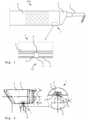
- FIG. 1 an exemplary embodiment of a surgical instrument 100 with a head part 3 and an accessory 7 guided therein is shown. Only a front area of the surgical instrument 100 is shown, in which a partial area of the housing 2 can be seen.
- the head part coupling 10 is arranged at a distal end of the surgical instrument 100 or the housing 2 .
- the head part coupling 10 is designed for the permanent mechanical connection of the head part 3 to the housing 2 .
- the housing 2 forms a shaft which is designed to accommodate a head part 3 .
- An accessory 7 is guided through the housing 2 and through the head part 3 and protrudes beyond the head part 3 at the distal end.
- the accessory 7 is designed as a cold loop. It is also conceivable to arrange a diagnostic hysteroscope as an accessory 7, optionally with 5 Fr. instruments, or an HF electrode for different indicators, as well as other instruments.
- the accessory 7 is an accessory that can be operated in a bipolar manner.
- an accessory that can be operated monopolarly or monopolarly and bipolarly can also be connected to the surgical instrument 100 .
- the head part 3 is designed in particular as a ceramic insert and is therefore dimensionally stable and durable.
- the connecting device 1 is shown in detail as an enlarged section.
- the enlarged section shows a sectional view so that the engagement of the head part 3 in the housing 2 can be seen.
- the head part coupling 10 has a pin element 4 which forms a positive connection between the housing 2 and the head part 3 .
- the pin element 4 is guided through a bore 5 in the housing 2 and is held in a formation 6 in the head part 3 . As a result, the pin element 4 cannot pierce the head part 3 .
- the pin element 4 is therefore held immovably in a radial direction.
- the pin element 4 forms in particular a local, in other words punctiform, fixation and therefore requires little installation space.
- the pin element 4 is oriented transversely to a longitudinal axis of the housing 2 .
- the area inside the head part 3 designed as a hollow cross section is not influenced by the pin element 4 .
- the pin element 4 ends flush with an outer surface of the housing 2 .
- the housing 2 is tubular in a front area of the surgical instrument 100 .
- the head part 3 is tubular, with a diameter of the head part 3 or the housing 2 in a range of 5 mm can lie. Therefore, a very precise welding process is required to perform a weld that fixes the pin member 4 to the housing 2 .
- a welding tool 8 for making such a weld seam is in 2 shown.
- the weld seam is preferably carried out using a laser welding process, so that very small tolerances can be implemented.
- the weld seam can be designed as a circumferential seam.
- a V-seam, a HV-seam or a Y-seam can be formed, for example.
- Other weld shapes are also conceivable.
- the positive connection between the head part 3 and the housing 2 in connection with the weld seam can effectively prevent the head part 3 from becoming detached and remaining in a patient, in particular in comparison to an adhesive connection from the prior art.
- the connecting device 1 can be implemented quickly and inexpensively, and is therefore just as cost-effective in comparison to embossing both components.
- the head part 3 can also be guided outside of the housing 2 .
- the bore 5 would be formed in the head part 3 and the formation 6 in the housing 2.
- the connecting device 1 can have two or more head part couplings 10, which are arranged along the circumference of the housing 2 or of the head part 3 are arranged in the front area of the surgical instrument 100 . This can further increase the stability of the connection.
Landscapes
- Health & Medical Sciences (AREA)
- Life Sciences & Earth Sciences (AREA)
- Surgery (AREA)
- Engineering & Computer Science (AREA)
- Plasma & Fusion (AREA)
- General Health & Medical Sciences (AREA)
- Otolaryngology (AREA)
- Physics & Mathematics (AREA)
- Veterinary Medicine (AREA)
- Biomedical Technology (AREA)
- Heart & Thoracic Surgery (AREA)
- Medical Informatics (AREA)
- Molecular Biology (AREA)
- Animal Behavior & Ethology (AREA)
- Nuclear Medicine, Radiotherapy & Molecular Imaging (AREA)
- Public Health (AREA)
- Cardiology (AREA)
- Surgical Instruments (AREA)
Abstract
Description
- Die vorliegende Erfindung betrifft eine Verbindungsvorrichtung für chirurgische Instrumente, sowie ein chirurgisches Instrument und ein Verfahren.
- Chirurgische Instrumente weisen oftmals eine Verbindungsvorrichtung und ein daran mittels einer Kopfteilkupplung anbringbares Führungselement für ein Zubehör auf. Das Führungselement bildet ein Kopfteil aus, das an einem distalen Ende des chirurgischen Instruments angeordnet ist.
- In der HF-Chirurgie wird bei der sogenannten Elektrotomie (auch Diathermie oder Elektrokaustik) und der Koagulation (Gerinnung) die thermische Wirkung von hochfrequentem Wechselstrom auf Gewebe ausgenutzt, um Zielgewebe zu durchtrennen und gegebenenfalls gleichzeitig oder stattdessen Blutungen zu stillen. Die chirurgischen Instrumente weisen dazu eine oder mehrere (Aktiv-) Elektroden an ihrem Zubehör auf, über welche der hochfrequente Wechselstrom in das Zielgewebe eines Patienten eingeleitet wird. Damit am Zielgewebe der gewünschte Effekt der Elektrotomie und/oder Koagulation auftritt, wird eine hohe Stromdichte am Zielgewebe eingebracht. Daher weisen (Aktiv-) Elektroden in der Regel eine geringe Oberfläche auf und sind dazu beispielsweise nadelförmig oder klingenförmig ausgebildet, um den angelegten hochfrequenten Wechselstrom mit möglichst hoher Stromdichte in das Zielgewebe einzubringen. Es können dabei entweder monopolar oder bipolar betriebene chirurgische Instrumente zum Einsatz kommen.
- Bei monopolar betriebenen chirurgischen Instrumenten ist an dem Zubehör des chirurgischen Instruments eine einzige Aktivelektrode angeordnet, über welche der hochfrequente Wechselstrom in das Gewebe eines Patienten eingeleitet wird. Damit von der einzelnen Aktivelektrode aus der Strom in das Gewebe eingeleitet werden kann, muss eine großflächige Gegenelektrode (Neutralelektrode) an dem Körper des Patienten als Gegenpol angebracht werden.
- Bei bipolar betriebenen chirurgischen Instrumenten sind an dem Zubehör des chirurgischen Instruments zwei Elektroden (Aktivelektrode und Neutralelektrode) angeordnet. Dabei wird von einer ersten Elektrode (Aktivelektrode) aus der hochfrequenter Wechselstrom direkt gegenüber der zweiten Elektrode (Neutralelektrode) in das Zielgewebe eingebracht.
- Ein monopolares oder bipolares chirurgisches Instrument kann als Resektoskop ausgebildet sein, insbesondere zur transurethralen Resektion. Bei einem bipolaren Resektoskop muss ein optimiertes Anschnittverhalten und eine präzise Schnitt- bzw. Koagulationsqualität während des gesamten Eingriffs sichergestellt sein.
- Das Kopfteil, insbesondere bei einem Resektoskop, ist an einem Schaft des chirurgischen Instruments angeordnet und bildet das frontale bzw. distale Element aus, das zur Führung des chirurgischen Instruments durch einen Körperabschnitt dient. Dafür muss das Kopfteil ausreichend stabil und langlebig ausgebildet sein. Durch das Kopfteil kann verschiedenartiges Zubehör, beispielsweise eine kalte Schlinge, ein diagnostisches Hysteroskop oder HF-Elektroden für unterschiedliche Indikatoren gehalten werden. Da das Kopfteil direkt an der durch eine Kraft beanspruchten Stelle angeordnet ist, muss dieses stabil an dem Schaft befestigt werden. Eine Fixierung des Kopfteils an dem Schaft kann beispielsweise durch eine Klebeverbindung vorgesehen sein.
- Vor diesem Hintergrund liegt der vorliegenden Erfindung die Aufgabe zugrunde, eine verbesserte Verbindungsvorrichtung für chirurgische Instrumente, insbesondere bipolar betreibbare chirurgische Instrumente, bereitzustellen.
- Erfindungsgemäß wird diese Aufgabe durch eine Verbindungsvorrichtung mit den Merkmalen des unabhängigen Patentanspruchs 1 sowie ein chirurgisches Instrument und ein Verfahren mit den Merkmalen der weiteren unabhängigen Patentansprüche gelöst.
-
- Eine Verbindungsvorrichtung für chirurgische Instrumente, mit einem Gehäuse, und mit einer Kopfteilkupplung, die an dem Gehäuse angeordnet und zum mechanischen Koppeln eines Kopfteils ausgebildet ist, wobei die Kopfteilkupplung ein Stiftelement aufweist, das derart ausgebildet ist, dass das Kopfteil mit dem Gehäuse unverschieblich fixierbar ist, wobei das Stiftelement mit dem Gehäuse über eine Schweißnaht unlösbar fixiert ist.
- Ein chirurgisches Instrument, insbesondere für die Hochfrequenzchirurgie, mit einer erfindungsgemäßen Verbindungsvorrichtung.
- Ein Verfahren zur Fixierung einer erfindungsgemäßen Verbindungsvorrichtung, wobei das Stiftelement mittels eines Laserschweißverfahrens an dem Gehäuse unlösbar fixiert wird.
- Die der vorliegenden Erfindung zugrundeliegende Idee besteht darin, durch eine formschlüssige Verbindung in Kombination mit einer Schweißnaht das Kopfteil unlösbar und unverlierbar an dem Gehäuse, insbesondere an einem Schaft des Instruments, zu fixieren.
- Das chirurgische Instrument kann insbesondere als monopolar und/oder bipolar betreibbares chirurgisches Instrument ausgebildet sein. Insbesondere in der Hochfrequenzchirurgie kann mit dem wahlweise monopolar oder bipolar betreibbaren chirurgischen Instrument Gewebe durchtrennt werden (Elektrotomie) sowie zusätzlich oder alternativ Blutungen gestillt werden (Koagulation). Das monopolar und bipolar betreibbare chirurgische Instrument kann beispielsweise ein durch einen Nutzer bzw. Bediener (z. B. Chirurg) von Hand oder ein durch einen Roboter(-arm) geführtes Instrument sein.
- Das Gehäuse kann integral bzw. einstückig ausgeführt sein oder aus mehreren Komponenten (z. B. Schalenelementen), die mit einander lösbar oder fest mechanisch verbunden sind, gebildet sein. Das Gehäuse kann zumindest teilweise aus einem Kunststoff, einem Metall oder einer Legierung gefertigt sein. Bevorzugt kann das Gehäuse zumindest teilweise aus einem biokompatiblen Werkstoff gefertigt sein.
- Das Gehäuse kann einen Schaft aufweisen, der über die Kopfteilkupplung mit dem Kopfteil unlösbar und sicher fixiert ist.
- Das Gehäuse ist insbesondere zumindest in dem Bereich, in dem es mit dem Kopfteil in Verbindung steht, rohrförmig ausgebildet und kann insbesondere einen Durchmesser von 4 mm bis 10 mm, beispielsweise 5 mm, aufweisen.
- Der Schaft ist bevorzugt zur zumindest teilweisen Aufnahme des Kopfteils ausgebildet. Beispielsweise kann der Schaft eine Art Außenrohr für das Kopfteil ausbilden. Insbesondere kann das Kopfteil mit einem Teilabschnitt in den Schaft eingesteckt werden, um das Kopfteil auszurichten und an die geometrisch gewollte Position zu bringen. Über die Verbindungsvorrichtung erfolgt daher insbesondere die unlösbare Fixierung des Kopfteils an dem Schaft. Die Verbindungsvorrichtung ist derart ausgebildet, dass ein damit mechanisch verbundenes Kopfteil unverlierbar gehalten werden kann.
- Die Kopfteilkupplung weist ein Stiftelement auf, das eine formschlüssige Verbindung zwischen dem Gehäuse, insbesondere dem Schaft, und dem Kopfteil ausbildet. Insbesondere ist das Stiftelement klein im Verhältnis zu einem Durchmesser des Kopfteils bzw. des Gehäuses ausgebildet. Das Kopfteil kann zur Führung eines Zubehörs ausgebildet sein.
- Das Kopfteil ist insbesondere ein Keramikeinsatz, der an einem distalen Ende des Schafts eingesteckt und über das Stiftelement formschlüssig fixiert wird.
- Die Schweißnaht ist bevorzugt durch ein Laserschweißverfahren hergestellt, sodass eine präzise und für einen gewünschten Toleranzbereich notwendige Schweißnaht ausgebildet werden kann.
- Mit der erfindungsgemäßen Verbindungsvorrichtung kann schnell und aufwandsarm das Kopfteil an dem Gehäuse unlösbar fixiert werden, sodass ein Herausfallen des Kopfteils während der OP, und ein Verbleib im Patienten, sicher vermieden werden kann.
- Vorteilhafte Ausgestaltungen und Weiterbildungen ergeben sich aus den weiteren Unteransprüchen sowie aus der Beschreibung unter Bezugnahme auf die Figuren der Zeichnung.
- Gemäß einer vorteilhaften Ausführungsform kann das Stiftelement durch eine Bohrung durch das Gehäuse hindurchgreifen und in eine Ausformung in dem Kopfteil eingreifen. Vorteilhaft ist ein Durchmesser der Bohrung an einen Durchmesser des Stiftelements angepasst, sodass das Stiftelement sicher an dem Gehäuse verschweißt werden kann. Insbesondere schließt das Stiftelement bündig mit einer Außenoberfläche des Gehäuses ab, sodass das chirurgische Instrument durch die Verbindungsvorrichtung nicht beeinflusst wird. Die Ausformung in dem Kopfteil kann als Senke bzw. topförmige Aufnahme ausgebildet sein. Das Stiftelement wird daher bevorzugt innerhalb der Ausformung gehalten und kann das Kopfteil nicht durchstoßen.
- Gemäß einer Weiterbildung kann das Stiftelement das Kopfteil mit dem Gehäuse formschlüssig verbinden. Auf diese Weise ist ein Verschieben des Kopfteils relativ zu dem Gehäuse unterbunden, wodurch das Kopfteil lagefixiert gehalten werden kann.
- Gemäß einer Ausführungsform kann das Gehäuse rohrförmig ausgebildet sein. Vorteilhaft ist auf diese Weise ein zumindest teilweises Einstecken des Kopfteils in das Gehäuse möglich. Das Gehäuse bildet bevorzugt einen Schaft aus, der einen Durchmesser von beispielsweise 5 mm bis 10 mm aufweisen kann. Weiterhin sind Durchmesser denkbar, die kleiner als 5 mm betragen. Die zur Verfügung stehende Wanddicke des rohrförmigen Gehäuses ist daher sehr gering, sodass ein Verschweißen des Stiftelements mit dem Gehäuse aufgrund der geringen Toleranzschwelle bevorzugt durch Laserschweißen erfolgt.
- Gemäß einer vorteilhaften Ausführungsform kann das Kopfteil rohrförmig ausgebildet sein. In einer derartigen Ausführungsform ist vorteilhafterweise das Gehäuse ebenso rohrförmige ausgebildet. Das Gehäuse kann dabei eine Art Außenrohr ausbilden, in das ein Teilbereich des Kopfteils eingesteckt wird. Die Durchmesser von Kopfteil und Außenrohr sind bevorzugt aneinander angepasst, sodass nur ein geringer Spalt entsteht.
- Gemäß einer vorteilhaften Ausführungsform kann durch das Kopfteil ein Zubehör durchführbar sein. Insbesondere kann ein monopolar und/oder bipolar betreibbares Zubehör durchführbar sein. Dies wird insbesondere dadurch ermöglicht, dass das Kopfteil einen Hohlquerschnitt ausbildet. Die Kopfteilkupplung, d. h. insbesondere das Stiftelement, beeinflusst den Bereich, der zur Durchführung des Zubehörs dient, nicht.
- Gemäß einer bevorzugten Ausführungsform kann das Stiftelement quer zu einer Längsachse des Gehäuses ausgerichtet sein. Vorteilhaft ist auf diese Weise eine formschlüssige Verbindung möglich, da das Stiftelement quer zu einer Belastungsrichtung bei einem Einführen bzw. bei einem Herausnehmen des chirurgischen Instruments in bzw. aus der Körperregion ausgerichtet ist.
- Gemäß einer bevorzugten Ausführungsform kann das Kopfteil Keramik enthalten oder aus Keramik ausgebildet sein. Auf diese Weise ist die Ausführung eines besonders stabilen sowie langlebigen Kopfteils möglich. Insbesondere können thermische Schäden am Kopfteil durch den Einsatz einer Keramik verhindert werden.
- Gemäß einer besonders bevorzugten Ausführungsform kann die Verbindungsvorrichtung für ein Resektoskop ausgebildet sein. Insbesondere kann es sich um ein 5-mm-Resektoskop handeln. Ein derartiges Resektoskop bietet aufgrund des sehr geringen Durchmessers die Möglichkeit, ambulant Infertilitätspatientinnen sowie Patienten mit Blutungsstörungen ohne Anästhesie zu behandeln. Dafür ist nur eine sehr geringe oder keine Dilatation notwendig. Insbesondere kann ein bipolares System ohne Rückführung des Stromflusses über den Schaft, d. h. über das Gehäuse, bereitgestellt werden. Das Kopfteil ist bevorzugt als Keramikeinsatz ausgebildet, und kann beispielsweise für kalte Schlingen, als diagnostisches Hysteroskop sowie für HF-Elektroden für unterschiedliche Indikatoren verwendet werden. Dabei kann eine effektive Resektion, Koagulation oder Vaporisation erreicht werden.
- Für das erfindungsgemäße chirurgische Instrument sowie das Verfahren zur Fixierung der Verbindungsvorrichtung gelten dieselben Merkmale und Vorteile, wie bezüglich der Verbindungsvorrichtung beschrieben, sodass im Einzelnen nicht darauf eingegangen wird.
- Die obigen Ausgestaltungen und Weiterbildungen lassen sich, sofern sinnvoll, beliebig miteinander kombinieren. Weitere mögliche Ausgestaltungen, Weiterbildungen und Implementierungen der Erfindung umfassen auch nicht explizit genannte Kombinationen von zuvor oder im Folgenden bezüglich der Ausführungsbeispiele beschriebenen Merkmale der Erfindung. Insbesondere wird dabei der Fachmann auch Einzelaspekte als Verbesserungen oder Ergänzungen zu der jeweiligen Grundform der vorliegenden Erfindung hinzufügen.
- Die vorliegende Erfindung wird nachfolgend anhand der in den schematischen Figuren der Zeichnung angegebenen Ausführungsbeispiele näher erläutert. Es zeigen dabei:
- Fig. 1
- ein Ausführungsbeispiel eines chirurgischen Instruments mit einem Kopfteil und einem darin geführten Zubehör;
- Fig. 2
- ein Ausführungsbeispiel eines chirurgischen Instruments beim Verschweißen der Kopfteilkupplung.
- Die beiliegenden Figuren der Zeichnung sollen ein weiteres Verständnis der Ausführungsformen der Erfindung vermitteln. Sie veranschaulichen Ausführungsformen und dienen im Zusammenhang mit der Beschreibung der Erklärung von Prinzipien und Konzepten der Erfindung. Andere Ausführungsformen und viele der genannten Vorteile ergeben sich im Hinblick auf die Zeichnungen. Die Elemente der Zeichnungen sind nicht notwendigerweise maßstabsgetreu zueinander gezeigt.
- In den Figuren der Zeichnung sind gleiche, funktionsgleiche und gleich wirkende Elemente, Merkmale und Komponenten - sofern nichts Anderes ausgeführt ist - jeweils mit denselben Bezugszeichen versehen.
- In
Fig. 1 ist ein Ausführungsbeispiel eines chirurgischen Instruments 100 mit einem Kopfteil 3 und einem darin geführten Zubehör 7 dargestellt. Von dem chirurgischen Instrument 100 ist lediglich ein Frontbereich dargestellt, in welchem ein Teilbereich des Gehäuses 2 zu sehen ist. Die Kopfteilkupplung 10 ist an einem distalen Ende des chirurgischen Instruments 100 bzw. des Gehäuses 2 angeordnet. Die Kopfteilkupplung 10 ist zum unlösbaren mechanischen Verbinden des Kopfteils 3 mit dem Gehäuse 2 ausgebildet. - Das Gehäuse 2 bildet einen Schaft aus, der zur Aufnahme eines Kopfteils 3 ausgebildet ist. Durch das Gehäuse 2 sowie durch das Kopfteil 3 ist ein Zubehör 7 geführt, das an dem distalen Ende über das Kopfteil 3 übersteht. In der Darstellung ist das Zubehör 7 als kalte Schlinge ausgeführt. Es ist ebenso denkbar, als Zubehör 7 ein diagnostisches Hysteroskop, optional mit 5 Charr.-Instrumenten, oder ein HF-Elektroden für unterschiedliche Indikatoren, sowie anderweitige Instrumente, anzuordnen.
- Das Zubehör 7 ist hier ein bipolar betreibbares Zubehör. Es kann selbstverständlich auch ein monopolar oder ein monopolar und bipolar betreibbares Zubehör an das chirurgische Instrument 100 angeschlossen werden.
- Das Kopfteil 3 ist insbesondere als Keramikeinsatz ausgebildet und dadurch formstabil und langlebig.
- Die Verbindungsvorrichtung 1 ist als vergrößerter Ausschnitt im Detail dargestellt. Der vergrößerte Ausschnitt zeigt eine Schnittdarstellung, sodass das Eingreifen des Kopfteils 3 in das Gehäuse 2 erkennbar ist. Die Kopfteilkupplung 10 weist ein Stiftelement 4 auf, das eine formschlüssige Verbindung zwischen dem Gehäuse 2 und dem Kopfteil 3 ausbildet. Das Stiftelement 4 ist durch eine Bohrung 5 in dem Gehäuse 2 geführt und wird in einer Ausformung 6 in dem Kopfteil 3 gehalten. Dadurch kann das Stiftelement 4 das Kopfteil 3 nicht durchstoßen. Das Stiftelement 4 ist daher in einer radialen Richtung unverschieblich gehalten.
- Das Stiftelement 4 bildet insbesondere eine lokale, mit anderen Worten punktförmige, Fixierung aus und benötigt dadurch wenig Bauraum. Das Stiftelement 4 ist quer zu einer Längsachse des Gehäuses 2 orientiert. Insbesondere wird der Bereich innerhalb des als Hohlquerschnitt ausgebildeten Kopfteils 3 durch das Stiftelement 4 nicht beeinflusst. Weiterhin schließt das Stiftelement 4 bündig mit einer Außenoberfläche des Gehäuses 2 ab.
- Das Gehäuse 2 ist in einem Frontbereich des chirurgischen Instruments 100 rohrförmig ausgebildet. Ebenso ist das Kopfteil 3 rohrförmig ausgebildet, wobei ein Durchmesser des Kopfteils 3 oder des Gehäuses 2 in einem Bereich von 5 mm liegen kann. Daher ist ein sehr präzises Schweißverfahren zur Ausführung einer Schweißnaht erforderlich, die das Stiftelement 4 an dem Gehäuse 2 fixiert.
- Ein Schweißwerkzeug 8 zur Ausführung einer derartigen Schweißnaht ist in
Fig. 2 dargestellt. Die Schweißnaht wird bevorzugt durch ein Laserschweißverfahren ausgeführt, sodass sehr geringe Toleranzen umgesetzt werden können. Die Schweißnaht kann als umlaufende Naht ausgeführt sein. Dabei kann beispielsweise eine V-Naht, eine HV-Naht oder eine Y-Naht ausgebildet werden. Andere Schweißnahtformen sind ebenso denkbar. - Durch den Formschluss zwischen dem Kopfteil 3 und dem Gehäuse 2 in Verbindung mit der Schweißnaht kann ein Lösen des Kopfteils 3 und ein Verbleiben in einem Patienten effektiv vermieden werden, insbesondere im Vergleich zu einer Klebeverbindung aus dem Stand der Technik. Weiterhin ist die Verbindungsvorrichtung 1 kostengünstig und schnell ausführbar, und damit ebenso kostengünstig im Vergleich zu einer Verprägung beider Bauteile.
- Obwohl die vorliegende Erfindung anhand bevorzugter Ausführungsbeispiele vorstehend vollständig beschrieben wurde, ist sie darauf nicht beschränkt, sondern auf vielfältige Art und Weise modifizierbar.
- Beispielsweise kann das Kopfteil 3 auch außerhalb des Gehäuses 2 geführt sein. In einer derartigen Ausführungsform wäre die Bohrung 5 in dem Kopfteil 3 und die Ausformung 6 in dem Gehäuse 2 ausgeformt. In einer weiteren nicht dargestellten Ausführungsform kann die Verbindungsvorrichtung 1 zwei oder mehr Kopfteilkupplungen 10 aufweisen, die entlang des Umfangs des Gehäuses 2 bzw. des Kopfteils 3 in dem Frontbereich des chirurgischen Instruments 100 angeordnet sind. Dadurch kann die Stabilität der Verbindung weiter gesteigert werden.
-
- 1
- Verbindungsvorrichtung
- 2
- Gehäuse
- 3
- Kopfteil
- 4
- Stiftelement
- 5
- Bohrung
- 6
- Ausformung
- 7
- Zubehör
- 8
- Schweißwerkzeug
- 10
- Kopfteilkopplung
- 100
- chirurgisches Instrument
Claims (10)
- Verbindungsvorrichtung (1) für chirurgische Instrumente (100), mit:einem Gehäuse (2);einer Kopfteilkupplung (10), die an dem Gehäuse (2) angeordnet und zum mechanischen Koppeln eines Kopfteils (5) ausgebildet ist;wobei die Kopfteilkupplung (10) ein Stiftelement (4) aufweist, das derart ausgebildet ist, dass das Kopfteil (3) mit dem Gehäuse (2) unverschieblich fixierbar ist,wobei das Stiftelement (4) mit dem Gehäuse (2) über eine Schweißnaht unlösbar fixiert ist.
- Verbindungsvorrichtung (1) nach Anspruch 1,
dadurch gekennzeichnet,
dass das Stiftelement (4) durch eine Bohrung (5) durch das Gehäuse (2) hindurchgreift und in eine Ausformung (6) in dem Kopfteil (3) eingreift. - Verbindungsvorrichtung (1) nach Anspruch 1 oder 2,
dadurch gekennzeichnet,
dass das Stiftelement (4) das Kopfteil (3) mit dem Gehäuse (2) formschlüssig verbindet. - Verbindungsvorrichtung (1) nach einem der vorstehenden Ansprüche,
dadurch gekennzeichnet,
dass das Gehäuse (2) und/oder das Kopfteil (3) rohrförmig ausgebildet ist. - Verbindungsvorrichtung (1) nach einem der vorstehenden Ansprüche,
dadurch gekennzeichnet,
dass durch das Kopfteil (3) ein Zubehör (7), insbesondere ein monopolar und/oder bipolar betreibbares Zubehör (7), durchführbar ist. - Verbindungsvorrichtung (1) nach einem der vorstehenden Ansprüche,
dadurch gekennzeichnet,
dass das Stiftelement (4) quer zu einer Längsachse des Gehäuses (2) ausgerichtet ist. - Verbindungsvorrichtung (1) nach einem der vorstehenden Ansprüche,
dadurch gekennzeichnet,
dass das Kopfteil (3) Keramik enthält oder aus Keramik ausgebildet ist. - Verbindungsvorrichtung (1) nach einem der vorstehenden Ansprüche,
dadurch gekennzeichnet,
dass diese für ein Resektoskop ausgebildet ist. - Chirurgisches Instrument (100), insbesondere für die Hochfrequenzchirurgie, mit:einer Verbindungsvorrichtung (1) nach einem der Ansprüche 1 bis 8; undeinem Zubehör (7), insbesondere einem monopolar und/oder bipolar betreibbaren Zubehör (7), welches durch das Kopfteil (3) geführt ist.
- Verfahren zur Fixierung einer Verbindungsvorrichtung nach einem der Ansprüche 1 bis 8,
dadurch gekennzeichnet,
dass das Stiftelement (4) mittels eines Laserschweißverfahrens an dem Gehäuse (2) unlösbar fixiert wird.
Applications Claiming Priority (1)
| Application Number | Priority Date | Filing Date | Title |
|---|---|---|---|
| DE102021132426.2A DE102021132426A1 (de) | 2021-12-09 | 2021-12-09 | Verbindungsvorrichtung für chirurgische Instrumente sowie chirurgisches Instrument und Verfahren |
Publications (2)
| Publication Number | Publication Date |
|---|---|
| EP4193945A1 true EP4193945A1 (de) | 2023-06-14 |
| EP4193945B1 EP4193945B1 (de) | 2025-11-05 |
Family
ID=84367659
Family Applications (1)
| Application Number | Title | Priority Date | Filing Date |
|---|---|---|---|
| EP22210541.3A Active EP4193945B1 (de) | 2021-12-09 | 2022-11-30 | Verbindungsvorrichtung für chirurgische instrumente sowie chirurgisches instrument und verfahren |
Country Status (3)
| Country | Link |
|---|---|
| US (1) | US20230181249A1 (de) |
| EP (1) | EP4193945B1 (de) |
| DE (1) | DE102021132426A1 (de) |
Citations (7)
| Publication number | Priority date | Publication date | Assignee | Title |
|---|---|---|---|---|
| US5971940A (en) * | 1998-02-20 | 1999-10-26 | Scimed Life Systems, Inc. | Surgical instrument with locking feature, split distal housing, and sharpened jaws |
| EP2140803A2 (de) * | 2006-10-07 | 2010-01-06 | Maquet Cardiovascular LLC | Vorrichtung zur Durchführung minimalinvasiver chirurgischer Eingriffe |
| US20110295066A1 (en) * | 2010-05-28 | 2011-12-01 | Gyrus Acmi, Inc. | Continuous flow endoscope systems |
| WO2016138443A2 (en) * | 2015-02-26 | 2016-09-01 | Stryker Corporation | Surgical instrument with articulation region |
| WO2017035221A2 (en) * | 2015-08-27 | 2017-03-02 | Boston Scientific Scimed, Inc. | Medical devices and methods |
| GB2567161A (en) * | 2017-10-03 | 2019-04-10 | Depuy Ireland Ultd Co | An attachment mechanism for a surgical instrument |
| RU206061U1 (ru) * | 2020-07-21 | 2021-08-18 | федеральное государственное бюджетное образовательное учреждение высшего образования "Московский государственный медико-стоматологический университет имени А.И. Евдокимова" Министерства здравоохранения Российской Федерации (ФГБОУ ВО МГМСУ им. А.И. Евдокимова Минздрава России) | Стриппер для выделения икроножного нерва у детей |
Family Cites Families (7)
| Publication number | Priority date | Publication date | Assignee | Title |
|---|---|---|---|---|
| US1510416A (en) * | 1922-04-15 | 1924-09-30 | Pietz Frederick | Forceps |
| IL135371A (en) * | 2000-03-30 | 2006-10-31 | Roie Medical Technologies Ltd | Resectoscope |
| DE60121229T2 (de) * | 2001-04-06 | 2007-05-24 | Sherwood Services Ag | Vorrichtung zum abdichten und teilen eines gefässes mit nichtleitendem endanschlag |
| US8037591B2 (en) * | 2009-02-02 | 2011-10-18 | Ethicon Endo-Surgery, Inc. | Surgical scissors |
| US9421062B2 (en) | 2010-11-05 | 2016-08-23 | Ethicon Endo-Surgery, Llc | Surgical instrument shaft with resiliently biased coupling to handpiece |
| US10219818B2 (en) * | 2015-07-24 | 2019-03-05 | Covidien Lp | Shaft-based surgical forceps and method of manufacturing the same |
| CN108348261B (zh) | 2015-11-10 | 2021-03-16 | 柯惠有限合伙公司 | 可重复使用的内窥镜外科手术施夹器 |
-
2021
- 2021-12-09 DE DE102021132426.2A patent/DE102021132426A1/de active Pending
-
2022
- 2022-11-30 US US18/071,725 patent/US20230181249A1/en active Pending
- 2022-11-30 EP EP22210541.3A patent/EP4193945B1/de active Active
Patent Citations (7)
| Publication number | Priority date | Publication date | Assignee | Title |
|---|---|---|---|---|
| US5971940A (en) * | 1998-02-20 | 1999-10-26 | Scimed Life Systems, Inc. | Surgical instrument with locking feature, split distal housing, and sharpened jaws |
| EP2140803A2 (de) * | 2006-10-07 | 2010-01-06 | Maquet Cardiovascular LLC | Vorrichtung zur Durchführung minimalinvasiver chirurgischer Eingriffe |
| US20110295066A1 (en) * | 2010-05-28 | 2011-12-01 | Gyrus Acmi, Inc. | Continuous flow endoscope systems |
| WO2016138443A2 (en) * | 2015-02-26 | 2016-09-01 | Stryker Corporation | Surgical instrument with articulation region |
| WO2017035221A2 (en) * | 2015-08-27 | 2017-03-02 | Boston Scientific Scimed, Inc. | Medical devices and methods |
| GB2567161A (en) * | 2017-10-03 | 2019-04-10 | Depuy Ireland Ultd Co | An attachment mechanism for a surgical instrument |
| RU206061U1 (ru) * | 2020-07-21 | 2021-08-18 | федеральное государственное бюджетное образовательное учреждение высшего образования "Московский государственный медико-стоматологический университет имени А.И. Евдокимова" Министерства здравоохранения Российской Федерации (ФГБОУ ВО МГМСУ им. А.И. Евдокимова Минздрава России) | Стриппер для выделения икроножного нерва у детей |
Also Published As
| Publication number | Publication date |
|---|---|
| US20230181249A1 (en) | 2023-06-15 |
| DE102021132426A1 (de) | 2023-06-15 |
| EP4193945B1 (de) | 2025-11-05 |
Similar Documents
| Publication | Publication Date | Title |
|---|---|---|
| DE60312873T2 (de) | Elektrochirurgisches instrument zum verschluss von gefässen | |
| DE602005001776T2 (de) | Bipolare elektrochirurgische Schlinge | |
| EP0536440B1 (de) | Instrument für die Hochfrequenzchirurgie zum Schneiden oder Koagulieren | |
| EP1297790B1 (de) | Chirurgisches Zielgerät | |
| DE3490633T (de) | Bipolares elektrochirurgisches Gerät | |
| EP1882456A2 (de) | Teilzielvorrichtung zum Anzielen einer arthroskopischen Operationsstelle für einen medizinischen Eingriff | |
| DE19706751A1 (de) | Elektrochirurgisches Gerät zum Abtragen von Gewebe in Körperräumen | |
| DE102005021304A1 (de) | Endoskopische Chirurgieeinrichtung für eine Argon-Plasma-Koagulation (APC) | |
| EP3838205B1 (de) | Resektoskop mit distaler elektrodenführung | |
| EP0530400A1 (de) | Instrument für die Hochfrequenzchirurgie zum Schneiden und/oder Koagulieren mit HF-Strom | |
| EP2725988B1 (de) | Trokarsystem | |
| DE102021102736A1 (de) | Elektrodeninstrument für ein Resektoskop und Resektoskop | |
| EP0918489B1 (de) | Trokarhülse für die endoskopie | |
| DE102020118265A1 (de) | Medizinisches Instrument und elektrochirurgisches System | |
| EP4193945B1 (de) | Verbindungsvorrichtung für chirurgische instrumente sowie chirurgisches instrument und verfahren | |
| DE102006039696A1 (de) | Vorrichtung zur Resektion und/oder Ablation von organischem Gewebe mittels Hochfrequenzstrom sowie Resektoskop | |
| EP3363395A1 (de) | Sondeneinrichtung für ein resektoskop oder ein anderes mikroinvasives instrument | |
| DE29617461U1 (de) | Chirurgische Vorrichtung | |
| DE10333956A1 (de) | Sichtobturator | |
| WO2005023122A1 (de) | Medizinisches instrument zum präparieren von gewebe | |
| EP3708103B1 (de) | Elektrodeninstrument und resektoskop mit greiffunktion | |
| EP3300675B1 (de) | Komponente für ein medizinisches instrument und medizinisches instrument | |
| EP3471642B1 (de) | Chirurgisches instrument für die elektrotomie und werkzeug dafür | |
| DE102023100244A1 (de) | Elektrode für ein elektrochirurgisches Handinstrument | |
| DE4223162A1 (de) | Greifvorrichtung zum Greifen chirurgischer Instrumente |
Legal Events
| Date | Code | Title | Description |
|---|---|---|---|
| PUAI | Public reference made under article 153(3) epc to a published international application that has entered the european phase |
Free format text: ORIGINAL CODE: 0009012 |
|
| STAA | Information on the status of an ep patent application or granted ep patent |
Free format text: STATUS: THE APPLICATION HAS BEEN PUBLISHED |
|
| AK | Designated contracting states |
Kind code of ref document: A1 Designated state(s): AL AT BE BG CH CY CZ DE DK EE ES FI FR GB GR HR HU IE IS IT LI LT LU LV MC ME MK MT NL NO PL PT RO RS SE SI SK SM TR |
|
| STAA | Information on the status of an ep patent application or granted ep patent |
Free format text: STATUS: REQUEST FOR EXAMINATION WAS MADE |
|
| 17P | Request for examination filed |
Effective date: 20231212 |
|
| RBV | Designated contracting states (corrected) |
Designated state(s): AL AT BE BG CH CY CZ DE DK EE ES FI FR GB GR HR HU IE IS IT LI LT LU LV MC ME MK MT NL NO PL PT RO RS SE SI SK SM TR |
|
| GRAP | Despatch of communication of intention to grant a patent |
Free format text: ORIGINAL CODE: EPIDOSNIGR1 |
|
| STAA | Information on the status of an ep patent application or granted ep patent |
Free format text: STATUS: GRANT OF PATENT IS INTENDED |
|
| RIC1 | Information provided on ipc code assigned before grant |
Ipc: A61B 18/14 20060101AFI20250515BHEP |
|
| INTG | Intention to grant announced |
Effective date: 20250530 |
|
| GRAS | Grant fee paid |
Free format text: ORIGINAL CODE: EPIDOSNIGR3 |
|
| GRAA | (expected) grant |
Free format text: ORIGINAL CODE: 0009210 |
|
| STAA | Information on the status of an ep patent application or granted ep patent |
Free format text: STATUS: THE PATENT HAS BEEN GRANTED |
|
| AK | Designated contracting states |
Kind code of ref document: B1 Designated state(s): AL AT BE BG CH CY CZ DE DK EE ES FI FR GB GR HR HU IE IS IT LI LT LU LV MC ME MK MT NL NO PL PT RO RS SE SI SK SM TR |
|
| REG | Reference to a national code |
Ref country code: CH Ref legal event code: F10 Free format text: ST27 STATUS EVENT CODE: U-0-0-F10-F00 (AS PROVIDED BY THE NATIONAL OFFICE) Effective date: 20251105 Ref country code: GB Ref legal event code: FG4D Free format text: NOT ENGLISH |
|
| REG | Reference to a national code |
Ref country code: DE Ref legal event code: R096 Ref document number: 502022006026 Country of ref document: DE |
|
| REG | Reference to a national code |
Ref country code: IE Ref legal event code: FG4D Free format text: LANGUAGE OF EP DOCUMENT: GERMAN |
|
| PGFP | Annual fee paid to national office [announced via postgrant information from national office to epo] |
Ref country code: DE Payment date: 20251126 Year of fee payment: 4 |
|
| PGFP | Annual fee paid to national office [announced via postgrant information from national office to epo] |
Ref country code: FR Payment date: 20251124 Year of fee payment: 4 |
|
| REG | Reference to a national code |
Ref country code: NL Ref legal event code: MP Effective date: 20251105 |
|
| PG25 | Lapsed in a contracting state [announced via postgrant information from national office to epo] |
Ref country code: ES Free format text: LAPSE BECAUSE OF FAILURE TO SUBMIT A TRANSLATION OF THE DESCRIPTION OR TO PAY THE FEE WITHIN THE PRESCRIBED TIME-LIMIT Effective date: 20251105 |
|
| REG | Reference to a national code |
Ref country code: LT Ref legal event code: MG9D |
|
| PG25 | Lapsed in a contracting state [announced via postgrant information from national office to epo] |
Ref country code: NO Free format text: LAPSE BECAUSE OF FAILURE TO SUBMIT A TRANSLATION OF THE DESCRIPTION OR TO PAY THE FEE WITHIN THE PRESCRIBED TIME-LIMIT Effective date: 20260205 |
|
| PG25 | Lapsed in a contracting state [announced via postgrant information from national office to epo] |
Ref country code: FI Free format text: LAPSE BECAUSE OF FAILURE TO SUBMIT A TRANSLATION OF THE DESCRIPTION OR TO PAY THE FEE WITHIN THE PRESCRIBED TIME-LIMIT Effective date: 20251105 Ref country code: HR Free format text: LAPSE BECAUSE OF FAILURE TO SUBMIT A TRANSLATION OF THE DESCRIPTION OR TO PAY THE FEE WITHIN THE PRESCRIBED TIME-LIMIT Effective date: 20251105 |
|
| PGFP | Annual fee paid to national office [announced via postgrant information from national office to epo] |
Ref country code: IT Payment date: 20251130 Year of fee payment: 4 |
|
| PG25 | Lapsed in a contracting state [announced via postgrant information from national office to epo] |
Ref country code: NL Free format text: LAPSE BECAUSE OF FAILURE TO SUBMIT A TRANSLATION OF THE DESCRIPTION OR TO PAY THE FEE WITHIN THE PRESCRIBED TIME-LIMIT Effective date: 20251105 |
|
| PG25 | Lapsed in a contracting state [announced via postgrant information from national office to epo] |
Ref country code: RS Free format text: LAPSE BECAUSE OF FAILURE TO SUBMIT A TRANSLATION OF THE DESCRIPTION OR TO PAY THE FEE WITHIN THE PRESCRIBED TIME-LIMIT Effective date: 20260205 |
|
| PG25 | Lapsed in a contracting state [announced via postgrant information from national office to epo] |
Ref country code: IS Free format text: LAPSE BECAUSE OF FAILURE TO SUBMIT A TRANSLATION OF THE DESCRIPTION OR TO PAY THE FEE WITHIN THE PRESCRIBED TIME-LIMIT Effective date: 20260305 |
|
| PG25 | Lapsed in a contracting state [announced via postgrant information from national office to epo] |
Ref country code: PT Free format text: LAPSE BECAUSE OF FAILURE TO SUBMIT A TRANSLATION OF THE DESCRIPTION OR TO PAY THE FEE WITHIN THE PRESCRIBED TIME-LIMIT Effective date: 20260305 |
|
| PG25 | Lapsed in a contracting state [announced via postgrant information from national office to epo] |
Ref country code: PL Free format text: LAPSE BECAUSE OF FAILURE TO SUBMIT A TRANSLATION OF THE DESCRIPTION OR TO PAY THE FEE WITHIN THE PRESCRIBED TIME-LIMIT Effective date: 20251105 |
|
| PG25 | Lapsed in a contracting state [announced via postgrant information from national office to epo] |
Ref country code: LV Free format text: LAPSE BECAUSE OF FAILURE TO SUBMIT A TRANSLATION OF THE DESCRIPTION OR TO PAY THE FEE WITHIN THE PRESCRIBED TIME-LIMIT Effective date: 20251105 |
|
| PG25 | Lapsed in a contracting state [announced via postgrant information from national office to epo] |
Ref country code: BG Free format text: LAPSE BECAUSE OF FAILURE TO SUBMIT A TRANSLATION OF THE DESCRIPTION OR TO PAY THE FEE WITHIN THE PRESCRIBED TIME-LIMIT Effective date: 20251105 |