EP4193570B1 - Verfahren und vorrichtung zur authentifizierung einer basisstation - Google Patents
Verfahren und vorrichtung zur authentifizierung einer basisstation Download PDFInfo
- Publication number
- EP4193570B1 EP4193570B1 EP21754980.7A EP21754980A EP4193570B1 EP 4193570 B1 EP4193570 B1 EP 4193570B1 EP 21754980 A EP21754980 A EP 21754980A EP 4193570 B1 EP4193570 B1 EP 4193570B1
- Authority
- EP
- European Patent Office
- Prior art keywords
- signature
- station
- time
- primary
- time reference
- Prior art date
- Legal status (The legal status is an assumption and is not a legal conclusion. Google has not performed a legal analysis and makes no representation as to the accuracy of the status listed.)
- Active
Links
Images


Classifications
-
- H—ELECTRICITY
- H04—ELECTRIC COMMUNICATION TECHNIQUE
- H04W—WIRELESS COMMUNICATION NETWORKS
- H04W12/00—Security arrangements; Authentication; Protecting privacy or anonymity
- H04W12/10—Integrity
- H04W12/108—Source integrity
-
- H—ELECTRICITY
- H04—ELECTRIC COMMUNICATION TECHNIQUE
- H04L—TRANSMISSION OF DIGITAL INFORMATION, e.g. TELEGRAPHIC COMMUNICATION
- H04L63/00—Network architectures or network communication protocols for network security
- H04L63/12—Applying verification of the received information
- H04L63/126—Applying verification of the received information the source of the received data
-
- H—ELECTRICITY
- H04—ELECTRIC COMMUNICATION TECHNIQUE
- H04L—TRANSMISSION OF DIGITAL INFORMATION, e.g. TELEGRAPHIC COMMUNICATION
- H04L9/00—Cryptographic mechanisms or cryptographic arrangements for secret or secure communications; Network security protocols
- H04L9/32—Cryptographic mechanisms or cryptographic arrangements for secret or secure communications; Network security protocols including means for verifying the identity or authority of a user of the system or for message authentication, e.g. authorization, entity authentication, data integrity or data verification, non-repudiation, key authentication or verification of credentials
- H04L9/3247—Cryptographic mechanisms or cryptographic arrangements for secret or secure communications; Network security protocols including means for verifying the identity or authority of a user of the system or for message authentication, e.g. authorization, entity authentication, data integrity or data verification, non-repudiation, key authentication or verification of credentials involving digital signatures
-
- H—ELECTRICITY
- H04—ELECTRIC COMMUNICATION TECHNIQUE
- H04W—WIRELESS COMMUNICATION NETWORKS
- H04W12/00—Security arrangements; Authentication; Protecting privacy or anonymity
- H04W12/06—Authentication
-
- H—ELECTRICITY
- H04—ELECTRIC COMMUNICATION TECHNIQUE
- H04W—WIRELESS COMMUNICATION NETWORKS
- H04W12/00—Security arrangements; Authentication; Protecting privacy or anonymity
- H04W12/12—Detection or prevention of fraud
- H04W12/121—Wireless intrusion detection systems [WIDS]; Wireless intrusion prevention systems [WIPS]
- H04W12/122—Counter-measures against attacks; Protection against rogue devices
Definitions
- the present invention relates to the field of wireless communications, and in particular to security aspects of the communication between a primary station, e.g. a base station, and a secondary station, e.g. a terminal or a mobile station forming a network.
- a primary station e.g. a base station
- a secondary station e.g. a terminal or a mobile station forming a network.
- Other entities may be present in such a network, such a security entity.
- terminals connect to the network in order to exchange data.
- Security is crucial in particular for wireless devices where a physical interaction is not required to access the network.
- Wireless networks must thus implement some measures to be able to exclude devices that are not authorized in the network.
- a conventional attack includes an attacker to impersonate an entity of the wireless network, and in particular the primary station, or base station.
- many countermeasures are aimed authenticating the identity of the various entities of the network.
- 3GPP is the organization in charge of the standardization of global solutions for mobile telecommunication systems.
- the telecommunication systems being developed in the 3GPP partnership are no exception.
- security measures are under discussions to reinforce the security of the network.
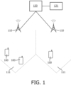
- secondary stations 100 act as terminals or end devices (also referred to as User Equipment, UE, in 5G).
- the secondary station can access different types of services including voice and data services through primary stations 110 acting as base stations (also referred to as gNB in 5G) that are deployed in field.
- Each primary station 110 serves and communicates with the secondary stations 100 present in an area, also referred as a cell 111.
- the primary stations are connected to a core network (CN) 120 - managed by a network operator - that controls the telecommunications systems and orchestrates the delivery of services.
- CN core network
- FBS False base stations
- a Signature Generator 121 as part of a Digital Signing network Function (DSnF) that will be part of the Core Network 120 and that will allow to protect the broadcast messages. It aims in particular at ensuring the source authentication.
- DnF Digital Signing network Function
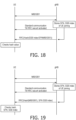
- a primary station 110 when it has to broadcast system information, it sends a request 201 to the Core Network 120, which transfers a corresponding request 202 to the Signature Generator 121.
- the Signature Generator 121 then compute a corresponding signature in 203 and provides the primary station 110 through the Core Network 120 with the signed messages 204 to that will be broadcasted at a later point of time 205.
- One aim of the present invention is alleviate the above mentioned problems.
- Another aim of the present invention is to provide with a method which allows to increase the difficulty for attackers to access or impersonate an entity of the network.
- Still another aim of the invention is a secondary station which is able to detect a false base station to ignore its messages.
- the method comprises the steps of
- the time reference information is at least one of the following: a time offset representative of the difference between a clock value at the primary station and a clock value at a Signature Generator of the network, a clock value at the primary station, a clock value at the Signature Generator.
- the step of deducing a local time reference includes computing an average from a plurality of the time reference information originating from primary stations with a valid signature and without duplicate cell identifier with earlier time.
- the step of deducing a local time reference includes selecting the time reference information with the latest value originating from primary stations with a valid signature.
- This variant thus uses the latest time displayed by the various validated primary stations. Thus, this helps to prevent a False Base Station using an old time value in order to replay past messages and pass the freshness criteria once in operation.
- the request is part of an Initial Radio Resource Communication, RRC, setup request message.
- the request may be part of a Network Access Stratum, NAS, identity response message sent in response to a NAS identity request.
- RRC Initial Radio Resource Communication
- NAS Network Access Stratum
- This aspect of the invention which can be used in combination with the first aspect of this invention in order to render the system even more reliant against attacks, presents the advantage of an early integration.
- this solution does not leak any secondary station information, despite adding some steps to the Radio Resource Control, RRC, setup procedure and state machine at the primary station.
- the received signature is checked using at least one of the following algorithm: a Public Key Infrastructure, PKI, algorithm, a Boneh-Lynn-Shacham, BLS, signing algorithm, a Boneh-Gentry-Lynn-Shacham, BGLS, signing algorithm, an Elliptic Curve Digital Signature Algorithm, ECDSA, Falcon signing algorithm, Rainbow signing algorithm, a Great Multivariate Short Signature, GeMSS, algorithm.
- a Public Key Infrastructure PKI
- algorithm a Boneh-Lynn-Shacham
- BLS Boneh-Gentry-Lynn-Shacham
- BGLS Boneh-Gentry-Lynn-Shacham
- ECDSA Elliptic Curve Digital Signature Algorithm
- Falcon signing algorithm Falcon signing algorithm
- Rainbow signing algorithm a Great Multivariate Short Signature
- GeMSS Great Multivariate Short Signature
- This secondary station is adapted for communicating in a network and comprises a receiver adapted to receive a plurality of system information, SI, messages from a plurality of primary stations, said SI messages including each a respective time reference information related to the corresponding primary station,
- the above apparatuses may be implemented based on discrete hardware circuitries with discrete hardware components, integrated chips, or arrangements of chip modules, or based on signal processing devices or chips controlled by software routines or programs stored in memories, written on a computer readable media, or downloaded from a network, such as the Internet.
- the present invention can be implemented in a cellular network as for example a 5G network.
- a cellular network comprises a plurality of terminals or secondary stations 100, being mobile devices (or UEs) that may travel from a network cell to another 111.
- Each cell 111 is served by a primary station 110 (or a gNodeB) which makes the interface between the secondary stations 100 and the Core Network 120.
- the secondary stations 100 communicate with the primary stations 110 on various radio channels, uplink (from the secondary stations to the primary station) and downlink (from the primary station to the secondary stations).
- Other radio channels exist, for example between secondary stations (for example Sidelink channels) and between primary stations (e.g. X2 interface), but are not represented for the sake of simplicity of Figure 1 .
- the embodiments of the invention could also be applied to these interfaces however it will be focused in the following parts of the description to the links between the secondary stations and the primary stations.
- the primary stations 110 may broadcast some configuration information over the cells 111.
- This configuration information includes Master Information Blocks (MIBs) and System Information Blocks.
- MIBs Master Information Blocks
- System Information Blocks System Information Blocks.
- the MIB is a message broadcasted periodically (e.g. every 80ms) and which includes all the required information to allow the decoding of the following SIBs.
- the secondary station can decode several System Information Blocks that can be transmitted periodically as well (e.g. every 80ms, 160ms) or on request from the secondary stations.
- SIBs describe the operation and parameters of the network.
- a digital signature is a technique that binds an entity to the digital data. This binding can be independently verified by receiver as well as any third party.
- a digital signature is a cryptographic value that is calculated from the data and a secret key known only by the signer. The data corresponds in the present case to the payload carried in the SIBs themselves. The signature allows the secondary station to have assurance that the message belongs to the primary station.
- one of the options available is that a Digital Signature Generator of the Core Network 120 generates and provides signatures to the primary stations 110 upon request from these primary stations for each message.
- Another option is that a Digital Signature Generator in included in each of the primary stations. This solution could be used for at least some of the messages, which would reduce the load on the Digital Signature Generators of the Core Network.
- One of the aspects of these signatures is to ensure that the signature was not added by a third party, e.g. an attacker that is replaying messages to impersonate a real primary station.
- a freshness value can be added to the signature to ensure that the signature was generated recently. Therefore, one option to verify the freshness of the information is by synchronizing clocks and checking that the information is not too old.
- Time is based on the time owned by the Signature Generator (DSnF) and the secondary stations (UEs) must know this time. This time might differ from the other time available to the secondary station or the time available at the primary station. However, this requires the secondary stations and entity generating the signature to be synchronized in some way.
- DnF Signature Generator
- UEs secondary stations
- the operation of the Signature Generator (DSnF), the primary station (gNB) and the secondary station to deal with time differences can be as follows:
- time should remain in sync during a long interval period of time. If this assumption does not hold, the primary station then asks again the Signature Generator to sign the time difference.
- the Signature Generator may then include in each signed message the latest static time difference with the primary station as well as its current time.
- the primary station may broadcast on a regular basis the signed messages including the time difference between primary station and the Signature Generator.
- the time of the primary station is broadcasted in System Information Block 9, SIB9 or could be broadcasted in other System Information messages. To reduce the communication overhead, this time may also be included in SIB1.
- GPS Time (in seconds) timelnfoUTC (in seconds) - 2,524,953,600 (seconds) + leapSeconds as defined in SIB9.
- the secondary station Upon reception of timing information in SIB1 and SIB9, the secondary station obtains the Signature Generator time and checks whether the received message is too old, e.g., not older than a signature validity duration, e.g., shorter than the System Frame Numbering/HyperFrame Numbering (SFN/HFN) duration (2h54'45"). In other words, the signed message is only valid for around 3 hours.
- a signature validity duration e.g., shorter than the System Frame Numbering/HyperFrame Numbering (SFN/HFN) duration (2h54'45"
- this time may be used to synchronize the secondary station clock once it joins a primary station and establishes a secure connection with the core network.
- the time distributed by the primary station provides a synchronization error of around 10 ms which is enough for the purposes of secure broadcast of System Information. Indeed, MIB and SIB1 are distributed with a periodicity of at least 80ms.
- a secondary station 100 first receives a plurality of system information, SI, messages from a plurality of primary stations 110, for example serving all the neighbouring cells at step S301.
- SI system information
- These SI messages include each a respective time reference information related to the corresponding primary station.
- This time reference would typically be the clock value at the Signature Generator at time of signature of the messages or the clock value of the primary station at the time of transmission of the SI messages.
- the time reference may also be based on the System Frame Number and/or the subframe number in which the SI messages were sent combined with a timing mapping reference which enables the secondary station to compute the absolute time.
- the secondary station checks the validity of a received signature for each of the primary stations. Any primary station for which the signature is not found valid is then ignored for the computation of the timing information.
- the secondary station then checks a cell identifier for each of the primary stations with a valid signature, and ignores time reference information from primary stations with a cell identifier being identical to another primary station. For example, the primary station having an earlier value than the primary station sharing the same cell identifier is excluded. This means that at step S303, the secondary station compares the cell identifiers of all the primary stations. If there are any duplicated cell identifiers, the secondary station assumes that primary station showing an earlier time value and a duplicated cell identifier are False Base Stations replaying past messages.
- the secondary station deduces a local time reference from one or more of the time reference information originating from primary stations with a valid signature.
- the secondary station after excluding False Base Stations at steps S302 and S303, can trust the remaining primary stations, and obtain a time reference with which the secondary station synchronizes its clock based on the deduced time for the purpose at least of checking freshness of the received messages.
- the time reference information may be a clock value at the primary station, or a clock value at the Signature Generator.
- the time reference may be a time offset representative of the difference between a clock value at the primary station and a clock value at a Signature Generator of the network.
- the secondary station can thereafter deduce the clock value of the Signature Generator from the clock value of the primary station or from the System Frame number of the message.
- the computation of the local time reference at step S304 may be performed by computing averaging some or all of the time reference information originating from primary stations with a valid signature and without duplicate cell identifier with earlier time. It may be advantageous to prefer first some of the detected primary stations for example on some priority or trust credit (e.g. based on hardware or firmware version).
- the step S304 includes selecting the time reference information with the latest value originating from primary stations with a valid signature and without duplicates with an earlier time.
- FIG. 5 is a block diagram representing a secondary station 500 in accordance with the first embodiment of the invention.
- This secondary station comprises a communication unit 501 including a receiver 502 and a transmitter 503 adapted for communicating in a network, for example in a 5G cellular network.
- the receiver 502 comprises at least one antenna or an antenna array with a plurality of antennas.
- This receiver may be adapted to receive messages sent from a plurality of primary stations.
- Such messages can be system information, SI, messages for configuration of the secondary station communication unit 501 in the communication network.
- SI messages includes each a respective time reference information related to their respective primary station.
- the secondary station 500 also include a controller 504 to control the operation of the secondary station. This controller may be a Computer Programming Unit or other combination of hardware and software.
- the controller 504 is configured to check the validity of a received signature for each of the primary stations, and to check a cell identifier at least for each of the primary stations with a valid signature, Then, the controller 504 ignores time reference information from primary stations with a cell identifier being identical to another primary station and having an earlier value than the one from the other primary station. Eventually, the controller 504 deduces a local time reference from one or more of the time reference information originating from primary stations with a valid signature.
- the secondary station In a second embodiment, which can be implemented independently from the first embodiment, but which can also be combined with the first embodiment, it is proposed for the secondary station to get direct access to the Signature Generator time.
- the first action to carry out by the secondary station is to get direct access to the Signature Generator time. No other actions must be carried out before this happens.
- the secondary station can start a secure time-request connection with the core network.
- the secondary station will include a nonce (e.g., a 128-bit or longer randomly generated value) to ensure the freshness of the handshake.
- the secondary station will start a local timer as well. This message does not need to be secure from the point of view of the secondary station.
- This message will be forwarded to the Signature Generator (DSnF) that will sign its current time and the received nonce.
- DnF Signature Generator
- the message is then sent to the secondary station through the primary station.
- the secondary station Upon reception of the message, the secondary station checks the validity of the signature and the presence of the nonce so that the secondary station knows that this message is not replayed and it is fresh.
- the secondary station may check whether to accept the message, if the timer does not exceed a given value, e.g., 20 ms. The secondary station may then correct the received Signature Generator time by adding timer/2. Given this time, the secondary station can proceed to check the validity of the signed system information and the time. If the received system information is recent, it can join the primary station. If it is not recent, the secondary station will disconnect from the primary station.
- a given value e.g. 20 ms.
- the secondary station may then correct the received Signature Generator time by adding timer/2. Given this time, the secondary station can proceed to check the validity of the signed system information and the time. If the received system information is recent, it can join the primary station. If it is not recent, the secondary station will disconnect from the primary station.
- An alternative to the above handshake is to perform any other secure time synchronization protocol with the Signature Generator to gain its time.
- This protocol could be integrated in the initial RRC setup procedure.
- An approach is to include the nonce in the RRCSetupRequest.
- the signed answer from the Signature Generator is included by the primary station in the RRCSetup message.
- the advantage of such an early integration is that this does not leak any information relative to the secondary station. However, it makes the RRC setup procedure and state machine at the primary station more complex.
- the nonce can be included in the NAS identity response message sent by the secondary station as answer to the NAS identity request.
- the AMF Core Access and Mobility Management Function
- the AMF forwards this to the Signature Generator for time signing.
- the answer should be provided before or at the same time that the AMF sends the NAS Authentication Request to the secondary station. In this way the secondary station can verify the time and the primary station certificates before engaging in any further communication.
- the secondary station may also at initial connection to the network send a request for a time reference at step S401, said request being addressed to a Signature Generator.
- This request may optionally be forwarded by the primary station to the Signature Generator, if this Signature Generator is in a separate entity than the primary station.
- the request for time reference includes a randomly generated number used as a nonce prepared by the secondary station.
- the secondary station receives a response message including the time reference and the nonce.
- the time reference and the nonce are signed with a nonce signature prepared by the Signature Generator.
- the secondary station checks at step S403 the authenticity of the received message by using the nonce and nonce. Eventually, the secondary station uses the received time reference to configure a clock at the secondary station.
- the request may be part of an Initial Radio Resource Communication, RRC, setup request message or of a Network Access Stratum, NAS, identity response message sent in response to a NAS identity request.
- RRC Initial Radio Resource Communication
- NAS Network Access Stratum
- the received signature is prepared by the Signature Generator using at least one of the following algorithm: a Public Key Infrastructure, PKI, algorithm, a Boneh-Lynn-Shacham, BLS, signing algorithm, a Boneh-Gentry-Lynn-Shacham, BGLS, signing algorithm, an Elliptic Curve Digital Signature Algorithm, ECDSA, Falcon signing algorithm, Rainbow signing algorithm, a Great Multivariate Short Signature, GeMSS, algorithm.
- the secondary station uses a corresponding algorithm to verify the validity of the signature.
- the Signature Generator relies on a time from a trusted external source (e.g., the current NIST beacon or the time from a known reference source), the secondary station can get the current time directly if it has a different type of connectivity, e.g., WiFi.
- the Signature Generator itself could also have a known API that can be known/preconfigured to the secondary station so that a secondary station can access the time source at any time as soon as it has access to the Internet.
- DSA Digital Signature Algorithm
- HASH is a hash function, e.g. a hash, a hash chain, or a Merkle Tree.
- the fixed_field is a field that can include one or more parameter values whose values are static by nature. By static, it is meant for example that a change of this static parameter configuration is unlikely to occur, for example as these are linked to the ground configuration of the cell.
- the changing_field includes typically more dynamic parameters values that are likely to be adjusted regularly, for example based on the current load of the cell or an interference status.
- This approach also reduces communication overhead since the fixed fields do not need to be submitted to Signature Generator in every single message. Instead, it can be communicated which fields remain constant and for how long, and the value of the changing fields. Similarly, when communicating with the Signature Generator, the primary station could only send HASH(fixed_field). Obviously, this has the risk that the Signature Generator does not have a chance of verifying the system information. This verification can be done once the Signature Generator; and at later iterations, the Signature Generator can only check that the hash of the fixed field does not change.
- the signature can be computed per MIB and SIB. However, it can also be computed over multiple blocks of SI including MIB, SIB1, SIB2 for example.
- the secondary station can for instance obtain a single signature for both MIB and SIB1 that form MSI.
- the signature itself can be in SIB1 and both MIB and SIB1 would need to be obtained to verify the signature. This could be advantageous in fact since MIB is very small and a long signature is unlikely to fit in it. However, it is important to verify the information transmitted in the MIB. Similarly, other information such as the PCI can be verified.
- the detected PCI, MIB, and SIB1 can be concatenated to sign them together. The resulting signature could be included in SIB1.
- the signature could be located in a new SIB that can be obtained on request by the secondary station. This can help to address backwards compatibility and reduces the communication overhead since it is only exchanged on demand.
- a secondary station can send a request including a nonce that will be forwarded by the primary station to the Signature Generator for signature. This approach ensures the freshness of the signed information.
- SIB1 includes the root of the Merkel tree that is signed. When device requests a different SIB, it is verified with that Merkle tree root.
- the method of the third embodiment further includes obtaining at step S603 a first hash value based on a first subset of the fields, the first subset of the fields consisting of one or more first field being relative to a parameter having a static value,
- the step S605 may be performed by comparing the received signature with a signature derived from the second hash value to authenticate the received configuration message.
- this embodiment allows to reduce the amount of messages a Signature Generator has to sign. Further, a stronger signature algorithm can be used to sign the static parameters of the configuration messages, thus reducing the load of computation on the secondary station as well while maintaining at least the same level of protection.
- the first hash value may have been computed for an initial message, and reused for each of the following configuration message. This avoids recomputing this first hash value multiple times.
- the step S603 of obtaining the first hash value includes applying a first hash operation onto the first subset of fields to obtain the first hash value, and storing the first hash value for subsequent use.
- the secondary station may apply a first hash operation onto the first subset of fields to obtain the first hash value, and store the first hash value for subsequent use in the memory upon determination that a valid first hash value is not present.
- the first hash value is considered valid if one or more of the following conditions is satisfied: the time elapsed since its generation is below a validity threshold, the identity of the primary station is authenticated, the primary station is the currently serving primary station.
- Such a validity threshold value can be signaled from the primary station or be equal to the periodicity of some System Information messages.
- the method of the third embodiment may include deriving the derived signature by applying a digital signature algorithm onto the second hash value.
- the digital signature algorithm is an ECDSA (Elliptic Curve Digital Signature Algorithm).
- step S701 receiving at a signature generator from a primary station at least one configuration message for configuring a secondary station, wherein said configuration message includes a plurality of fields relative to respective parameters.
- the signature generator then obtains at step S702 a first hash value based on a first subset of the fields, the first subset of the fields consisting of one or more first field being relative to a parameter having a static value.
- the signature generator can then apply at S703 a second hash operation on a combination of the first hash value and a second subset of the fields to obtain a second hash value, the second subset of fields consisting of one or more second field being relative to a parameter having a variable value, generating a signature derived from the second hash value to authenticate the configuration message.
- this step may be performed at the primary station after reception of the first has value.
- the signature generator transmits to the primary station the signature.
- the step of obtaining the first hash value may comprise one of the following steps:
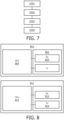
- a secondary station 801 comprises a communication unit 802 including a receiver 803.
- This receiver 803 is adapted to receive at least one configuration message from a primary station, wherein said configuration message includes a plurality of fields relative to respective parameters.
- the receiver is also configured to receive a received signature for authenticating the configuration message from the primary station.
- the secondary station also includes a controller 804 which is configured to obtain a first hash value based on a first subset of the fields, the first subset of the fields consisting of one or more first field being relative to a parameter having a static value.
- This controller may be a Computer Programming Unit or other combination of hardware and software.
- the controller can perform a second hash operation on a combination of the first hash value and a second subset of the fields to obtain a second hash value, the second subset of fields consisting of one or more second field being relative to a parameter having a variable value and then to verify the received signature on the basis of the second hash value to authenticate the received configuration message.
- the Signature Generator 811 of Figure 8 is adapted to generate a signature for authenticating a set of information.
- the signature generator 811 comprises a receiver 812 adapted to receive from a primary station at least one configuration message for configuring a secondary station, wherein said configuration message includes a plurality of fields relative to respective parameters.
- This receiver 812 typically comprises an antenna or an antenna array it is connected wirelessly to the primary station.
- this communication unit may be wired, so for example based on an Ethernet connection or an optical fiber connection linking it to a primary station.
- the Signature Generator is present in the primary station itself. In such a case, the receiver is a logical receiver that receives packets from higher layers and are processed by the Signature Generator 811.
- the signature generator comprises a controller 813 to obtain a first hash value based on a first subset of the fields, the first subset of the fields consisting of one or more first field being relative to a parameter having a static value.
- the signature generator controller 813 can apply a second hash operation on a combination of the first hash value and a second subset of the fields to obtain a second hash value, the second subset of fields consisting of one or more second field being relative to a parameter having a variable value.
- the controller is configured to generate a signature derived from the second hash value to authenticate the configuration message.
- the signature generator comprises a transmitter 814 to transmit to the primary station the signature.
- the Signature Generator is present in the primary station itself.
- the transmitter is a logical transmitter that transmits packets to lower layers of the primary station.
- MIB Master Information Block
- SIB1 SI message
- GeMSS and Rainbow are the only feasible quantum-resistant options -- having signature sizes between 34 and 64 bytes long -- assuming that their very bulky public-keys can be pre-configured on the end devices. It might also happen that with further scrutiny these solutions become less efficient or are even broken.
- a proposed signing solution may be based on a combination of a strong (QR) Digtial Signature Algorithm (DSA) and a lightweight DSA.
- the strong (QR)DSA can be ECDSA using long keys, e.g., equivalent to AES128 or higher.
- the lightweight DSA can be ECDSA using small keys, just strong enough to sign the information during a short period of time.
- the lightweight DSA can be based on a lightweight signature algorithm based on hash chains. This example is the method used in the remaining of the description, but it can be replaced by ECDSA with short keys or other combinations of DSAs.
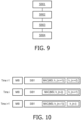
- Such a method comprises a step S901 of receiving a sequence of configuration messages from a primary station at a secondary station.
- the secondary station may receive for each configuration message at least one corresponding signature.
- a single signature may be used for a set of configuration messages (e.g. MIB+SIB1).
- the secondary station selects at least one digital signature algorithm out of a set of digital signature algorithms, depending on a time reference. This means that, depending on the time instant one or the other DSA algorithm is selected and used to verify the received messages.
- the secondary station verifies the received signature based on the selected digital signature algorithm.
- a public key may also be used to verify the received signatures.
- a first digital signature algorithm is selected more frequently than a second digital signature algorithm. For example, a shorter signature may be used more frequently as it leads to less overhead. Then, with a longer periodicity, a longer signature may be used.
- the first signature algorithm is less complicated than the second digital algorithm. This means that the first algorithm requires less computation power to generate and/or to verify the signature than the second algorithm.
- the periodicity with which the second algorithm is used equals k times a configuration period. This configuration period is, e.g., a periodicity of variable parameters. The second period may for example be the SFN duration.
- the second algorithm may be an ECDSA.
- the first Signature algorithms may be based on hash, for example a hash chain, used in the shorter intervals, only when the second Signature algorithm is not used.
- the first signature algorithm is always included, which means that in case when the second algorithm is used, the configuration messages include two signatures.
- the messages in the second period can include the signature of the fields that remain static during the second period, one of those fields is the public-key used to verify the configuration messages that are sent with a configuration period, in a similar manner as in the third embodiment.
- the configuration message can be sent periodically with a configuration period, and a second digital signature algorithm is selected periodically once every second period, wherein the second period is a multiple of the configuration period, said multiple being at least 2.
- a first digital signature algorithm is selected otherwise or for every message.
- the first algorithm may be based on at least one of a hash chain algorithm, a Boneh-Lynn-Shacham, BLS, signing algorithm, a Boneh-Gentry-Lynn-Shacham, BGLS, signing algorithm and wherein the second algorithm may be at least one of an Elliptic Curve Digital Signature Algorithm, ECDSA, Falcon signing algorithm, Rainbow signing algorithm, a Great Multivariate Short Signature, GeMSS, algorithm.
- the first algorithm is an Elliptic Curve Digital Signature Algorithm, ECDSA
- the second algorithm is also an ECDSA, however, the first algorithm uses shorter keys than the second algorithm.
- the configuration message may thus include a plurality of fields relative to respective parameters.
- a first digital algorithm of the digital signature algorithms includes the steps of obtaining a first hash value based on a first subset of the fields, the first subset of the fields consisting of one or more first field being relative to a parameter having a static value.
- a second hash operation is applied on a combination of the first hash value and a second subset of the fields to obtain a second hash value, the second subset of fields consisting of one or more second field being relative to a parameter having a variable value.
- a second digital algorithm of the digital signature algorithms may include the steps of applying a first hash operation to obtain value based on a first subset of the fields, the first subset of the fields consisting of one or more first field being relative to a parameter having a static value.
- the proposed signing solution in the fourth embodiment may be based on TESLA (which is hash chain based) and a (QR) DSA.
- TESLA describes a secure broadcast approach enabling source authentication which is given by a hash chain HC: h_ ⁇ n ⁇ ⁇ - h_ ⁇ n-1 ⁇ ⁇ - h_ ⁇ n-2 ⁇ ⁇ - ... ⁇ - h_ ⁇ 0 ⁇ , at time i, where h_ ⁇ n-i ⁇ can be used to compute a message authentication code (MAC) of message m as MAC(m, h_ ⁇ n-i ⁇ ).
- MAC message authentication code
- h_ ⁇ i+1 ⁇ hash(h_ ⁇ i ⁇ ).
- the value h_ ⁇ n-i ⁇ is disclosed at time i+1 allowing the receiving parties to verify the previously received MAC by checking
- h_ ⁇ 0 ⁇ is the seed of the HC from which all values are derived.
- h_ ⁇ n ⁇ is the trust anchor that needs to be distributed in a secure and trusted way to all devices.
- the Signature Generator may have both seeds of hash chains and a pair of public/private keys of a suitable DSA, e.g., ECDSA or a QR DSA.
- the primary station station gNB and the Signature Generator DSnF run a protocol to synchronize their clocks so that the DSnF is aware of the current time of the primary station and can correct any communication delays.
- a primary station gNB can ask the Signature Generator for the MAC of a message for time i on demand.
- the Signature Generator may use the hash chain links to efficiently compute the corresponding MACs that delivers to the base station. It is to be noted that these communication flows can be done in advance.
- the Signature Generator makes use of the time synchronization protocol to be aware of any potential time difference between clocks that is included in the signed messages.
- the primary station can broadcast to the secondary stations the signed system information, which has been provided by the Signature Generator, at the right instants of time afterwards.
- the Signature Generator may distribute to all subscribed primary stations the used hash chain elements h_ ⁇ n-i ⁇ at time i, that are then further broadcasted by the primary stations to the secondary stations.
- the first flow of data can be done on demand, i.e., when source authenticated information needs to be signed so that it can be broadcasted at a later point of time.
- the second communication flow in which the hash chain elements are disclosed requires tight synchronization.
- the Signature Generator has to distribute with the same frequency the next hash chain element, and this element is broadcasted to all UEs as part of the SI.
- MSI MIB + SIB1
- Time i can represent in this case, e.g., a 160 ms slot.
- the Hash Chain link used to compute the previous MACs is disclosed. This means, e.g., that all messages within a 160 ms interval use the same Hash Chain link.
- Such a Hash Chain approach is shown for example on Figure 10 , representing the sequence of configuration messages and their corresponding signatures.
- the secondary station keeps track of the System Information blocks and it has been initialized with the Hash Chain anchor, then the verification is very fast since a single hash computation is required to verify the previously received hash value.
- the secondary station When the secondary station is new to the system, it needs to first receive and verify the HC anchor. Distributing it after the initial NAS handshake is not an option since it can mean that the UE joins a FBS. Thus, going around an actual digital signature algorithm (DSA) does not seem feasible.
- DSA digital signature algorithm
- a very suitable option consists in having a combination of a traditional signing algorithm and hash chain.
- the Signature Generator signs the next hash chain anchor with a digital signature algorithm (DSA) and distributes it to the primary stations that broadcast it to all secondary stations.
- DSA digital signature algorithm
- the periodic MIB/SIB1 may be signed at short_interval period of time by means of a MAC following the hash chain approach. This is shown in figure 11 where the DSA signed anchor is distributed at time 1.
- This approach combines Hash Chain and Digital Signature Algorithm. With this approach, when the secondary station is joining primary station serving a cell, it requires acquiring the Hash Chain anchor and verifying the Signature. This may leads to a small delay, but afterwards the CPU performance increases a lot since verification is based on a simple hash. If the Signature Generator owns both the private key and the seed of the hash chain, then a secondary station can acquire a Hash Chain anchor that can be valid for multiple primary stations. Thus, this decreases the resource requirements when a secondary station scans multiple primary stations.
- the Signature Generator is in charge of signing with the second signature algorithm the anchor of the hash chain used during a long_interval.
- the DSA can also check that the anchor corresponds to a known seed known to a primary station only (this requires confidentiality in the exchange between the Signature Generator and the primary station).
- the Signature Generator will sign a single time all parameters that remain static in the long_interval period of time.
- the The Signature Generator provides the primary station with the signed anchor and signed fixed parameters. The primary station keeps broadcasting these fixed parameters as indicated in Figure 11 during the long interval.
- the signature of static fields of multiple SIBs can be located in SIB1 or a new SIB. If it is included in a new SIB, this SIB can be sent to the secondary station on demand decreasing energy consumption.
- the remaining SI e.g., SIB1, SIB2, etc contain a MAC computed with the hash-chain based approach that allows for fast verification of dynamic fields.
- a Hash Chain approach is feasible.
- the DSA signature can be included more frequently than the SFN interval to allow for a faster acquisition of the Hash Chain anchor and more frequent verification of static parameters.
- the primary station can send a request to the Signature Generator to sign the static parameters every long_interval time and during that long_interval, the primary station can keep broadcasting that signature for the fixed parameters and signs itself the dynamic parameters using the Hash Chain-based approach.
- the DSA signature can be fragmented over multiple messages with the purpose to sign a single anchor. For instance, if in every SIB1 we can include a fragment of 64 bytes and the signature+certificate signing a 32 byte anchor is 1600 bytes long, we can split the signature+certificate in 25 consecutive messages. It could be also a single new SIB, but having a fragmentation field to indicate the fragment number. If a new message is broadcasted every 160 ms, then the long interval is at least 4 seconds long. Still, this approach ensures that every single message can be signed and verified when the secondary station has acquired the anchor (faster verification) and that the verification is faster.
- the secondary station if the secondary station does not have the anchor yet, it needs to wait 4 seconds till it can start verifying all messages.
- the system broadcasts the signature of both the new anchor and of the old anchor. This allows the secondary station to start receiving packets, e.g., starting with h_(n-i), pre-verifying them with the hash-based approach, and as soon as the old anchor h_0 is received, the secondary station can compute n-i hashes to complete the verification.
- the system can be enhanced by including the hash of the messages protected with the HC approach as input of the message that is signed with the DSA algorithm. This means that an attacker cannot use misuse those values at its will.
- the broadcasted anchors can be part of different hash chains, i.e., having two different seeds, or intermediate links in a same hash chain separated by n hash operations.
- the hash anchor is encoding using the following format:
- XYZ...XYZ correspond to the actual hash value, i.e., h_(n-i). This differentiation is important so that if a secondary station is already listening to the primary station for some time, the verification of a new anchor that is an intermediate link in the previous hash chain can be performed faster with a single hash operation.
- the Signature Generator performs the verification of primary station by doing the following:
- a secondary station can also have access to the location information of primary station. Therefore, according to the fifth embodiment, it is proposed a method for validating the identity of a primary station, the method comprising receiving at least one signal at a secondary station. The secondary station then determines a location parameter based on said received signal. Then, the determined location parameter is compared to a reference location parameter linked to the identity of the primary station to decide whether the primary station is trustworthy.
- the secondary station can determine if the received signal is likely to originate from the site of a real primary station. This renders an attack more difficult since the physical location could exclude part if not all of the false primary station of such an attacker.
- the determination of the location parameter comprises estimating a radiation pattern of the primary station, and wherein comparing the determined location parameter to a reference location parameter includes comparing the estimated radiation pattern to a reference radiation pattern of the primary station.
- the secondary station may take into account its own location to determine reference radiation pattern.
- the estimation of the radiation pattern by the secondary station may include counting the number of detected radiation beams for a primary station. The secondary station then compares this number of radiation beams to a reference radiation pattern in the form of a reference list.
- a reference list may include for each referenced primary station the number of radiation beams the primary station is using or a maximum number of beams the primary station is capable of using.
- the listed reference list may include the identity (e.g. PCI) of the primary station. It can also include the location (e.g. GPS coordinates) of the referenced primary stations.
- this above method has the advantage that it can also be used for UEs in very bad deployment scenarios, and does not require very dense information from the base station related to the expected radiation pattern (e.g., radiation pattern for each point in space (steps of 1 mm, cm, m) around the base station) to be able to perform the similarity check. It also does not require the knowledge about the exact position of the base station and UE, as the similarity check of the radiation pattern consists in just counting the number of SSB beams that are present in the broadcasted signal of a base station. This amount of information is very limited, it is just the number of SSBs associated to a Physical Cell Identifier (PCI). The PCI is also broadcasted as part of the synchronization block. Based on this information that a UE can receive out-of-band or in a secure way the first time a UE connects to the network, the UE can do the following:
- the reference radiation pattern may be obtained from a database of primary stations.
- the application mastdata offers this data.
- Another possibility is that network operators who trust each other exchange the positions of the primary stations creating a combined list of primary stations.
- the primary stations located in the tracking area where the secondary station is located are stored on the secondary station.
- the secondary station can only exclude that primary station.
- the secondary station may collect a radiation pattern and report it to a known primary station which, optionally in collaboration with the network, check the received radiation pattern. This can be done single radiation pattern by single radiation pattern or it could include the preliminary step of the secondary station collecting over a period of time a plurality of radiation patterns and report them (as a whole, or iteratively) to the known primary station. Location of the secondary station corresponding to each measured radiation pattern may be included.
- the location of the primary station can be estimated, in addition to (or instead of) the number of radiation beams, by taking into account that a primary station broadcast the synchronization signals using different beams radiated in different directions and using a different identifier as can be shown on Figure 12 .
- SSS refers to the Secondary Synchronization Signal identifier
- PSS refers to the Primary Synchronization Signal identifier.
- the PSS and SSS are transmitted as part of a Synchronization Signal Block (SS Block).
- SSBs is transmitted in a batch by forming an SS Burst (one SSB per beam) that is used during beam sweeping by changing beam direction for each SSB transmission.
- the maximum number of SSBs in an SS Burst is frequency-dependent and it can be 4 (below 3 GHz), 8 (3 to 6 GHz), or 64 (6 to 52.6 GHz).
- the periodicity of the SSB is configured by the network, while the default transmission periodicity for initial cell selection, the SS burst set periodicity is default at 20ms for all frequency ranges i.e., 2 NR frames.
- the primary station defines multiple candidate positions for SSBs within a radio frame.
- Each SSB radiated in a different direction, can be identified by a unique number called SSB index and identification of which SSB is detected is depend on where secondary station is located.
- the secondary station can measure the signal strength of Demodulation Reference Signal (PBCH DMRS) of each SSB it detected for a certain period (a period of one SSB Set). From the measurement result, the secondary station can identify the SSB index with the strongest signal strength. This SSB with the strongest signal strength is the best beam for the secondary station.
- PBCH DMRS Demodulation Reference Signal
- the secondary station knows the normal radiation pattern (number and/or direction of the SB#) of a primary station and its own location (e.g. by GPS), and has measured a primary station, has information about the PCI, and the best SBs and relative received power can have an indication whether the primary station is real or false.
- an attacker places a FBS targeting UE1. Since the UE1 makes use of the technique used in this part of the invention, the FBS has to redirect its beams so that UE1 receives the same transmission signature. That is why the beam 1201 is pointing towards it.
- the FBS will successfully target UE1, but other UEs (e.g., UE2) can still differentiate between the real BS and the FBS since the radiation pattern changes.
- the secondary station can derive what the expected received radiation pattern should be.
- a secondary station 1200 has an omnidirectional antenna. For instance, if a secondary station knows its position and that the beam 1201 points towards it, the beam 1203 goes in the opposite direction and that the beams 1202 and 1204 go in perpendicular directions, then the secondary station 1100 can expect the biggest signal strength for the beam 1201, the lowest for the beam 1203, and intermediate values for the beams 1202 and 1204.
- the expected relative signal strength scan be derived from the gain distribution of the antenna for the different beams given the specific position of secondary station 1200 since it can compute its relative position, and with it, it can compute the gain of the antenna towards the secondary station 1200 for the different beams. It can now compare this expected signal with the received signal by computing the cross-correlation. If the signals are aligned, the maximum should be around the zero. If the cross-correlation outputs a maximum much further away than 0, then the primary station can be classified as a potential fake base station.
- This method may not always give guarantees or prevents an attacker from attacking a specific target secondary station, but it can reduce the number of devices that can be addressed by a FBS to a much smaller fraction of them reducing the overall risk.
- a UE can also keep track of the gNB beams that it is using for its communication. For instance, in an interval of 1 minute, in steps of 10 seconds, while UE was moving, the UE might have seen the following beams: [B_1, B_32, B_32, B_19, B_45, B_45]
- the UE can collect these beam statistics and the timing (e.g., UTC time) and send them to the gNB in a protected manner.
- the gNB can then compare whether the beams used to communicate with the UE are the same beams that the gNB actually used. If a MitM is in place, this is very unlikely to be the case, and thus, the gNB will detect the MitM presence.
- a secondary station for example a UE, sends a report of the collected physical information to the core network.
- This report can be seen as an extension of Annex E of TS 33.501 for UE-assisted network-based detection of false base station.
- the network can combine the information of multiple secondary stations (UEs) including the UEs locations and the received radiation pattern signal to estimate where base stations and fake base stations are.
- UEs secondary stations
- the UE can report the measured beams at a given time and location. For instance, the following data can be included in a UE report to the network: for each time t_i, the location of the UE I_i, and the set of beams measured.
- a given beam B can include PCI identifier, beam index number, and measured power. Such a report is illustrated as follows:
- SSB index beam indexes
- the above can also refer to beam indexes used during operation.
- the core network can use this information to determine the presence of a fake base station, even if the fake base station is targeting a very specific area. To this end, the core network will recreate a map of measurements for the beams associated to a given base station, e.g., the SSB indexes during cell acquisition. If a fake base station tries to spoof the identity of another base station at a close-by position, the fake base station will create a radiation pattern that is not expected. The location of the fake base station can be roughly determined by finding the geometric center of the measured beams.
- the UE can perform a handover.
- the UE can inform its current gNB it is connected to about its preferred target gNB, including a report of the signal strength of the different beams/gNBs as received by the UE.
- the current gNB can check whether this measured radiation pattern of the different beams/gNBs is as expected or not.
- the current gNB might also inform at this stage, knowing UE's location, what the expected radiation pattern is so that the UE can cross-check what is expected with its measured radiation pattern. If an anomaly is detected, the UE can inform the gNB (in the case that the detection is at the UE side) or the gNB can inform the UE about such anomaly and indicate that a different target gNB/beam is preferred.
- the network triangulates the signals to estimate the positions of the base stations.
- the UEs can also report other positioning information from the base stations such as positioning reference signals (PRS) such as signal strength or angle of arrival as described in Solution 22 in TR 33.809-v0.10.0.
- PRS positioning reference signals
- the network can inform the UE of its presence so that this fake base station is excluded. The network can also take further action.
- the process can thus be summarized as: a) UEs send to network measurements of the base stations regarding location (received radiation pattern, UE location, signal strength, angle of arrival, etc b) While positions do not match, do the following: b1) take subset of N available UE measurements from the BS stations b11) Network estimates the position of the UEs based on the chosen subset and compares it with the shared UE position. b12) Given the estimated positions of the UEs, and the reports from the UEs, the network can estimate the positions of the base stations by using either signal strength & angle of arrival, or using triangulation with received radiation pattern, or combining both approaches
- determining a location of a potential fake primary station includes comparing the index of the beam included in the radiation pattern with a reference.
- an entity (possibly placed in the network or the primary station) receives a measurement report including some indication of an estimated radiation pattern, and the entity analyzes the received measurement report including some indication of a radiation pattern to determine whether a Fake primary station is present in the network. This determination can be done by comparison with a reference radiation pattern or by monitoring changes over time, or by cross checking measurement reports from a plurality of different UEs.
- the secondary station may monitor PBCH parameters when estimating the radiation patterns.
- the monitoring may include measuring the strength of the PBCH DMRS for each SSB.
- An alternative or complementary solution is to keep a log of primary stations in a well-known data base that could be denoted as base station log (BSLog) or multiple data bases operated by multiple parties.
- BSLog base station log
- One option is to construct this base station log based on information owned by the network operators who know the location and configurations of the base stations.
- a secondary station can then request the BSLog information of the primary stations located close by.
- a further option is to build public BSLogs where users can submit their measurements or the scanned base stations and network operators can also publish the available base stations. Such data bases exist, even if they do not seem to be widely extended. An example of them is mastdata. If such a BSLog exist, a UE can verify whether the estimated location of the primary station matches the location of this primary station included in the BSLog providing additional assurances. Since the decisions of the secondary station depend on the contents of the BSLog, it is fundamental the BSLog is trusted. Increased trust can be achieved if there are multiple BSLogs that can be externally audited. In order to avoid that the BSLog manipulates its entries, the entries can be combined by means of a Merkle tree verification tree where the tree root is made public.
- the BSLog can determine that measurements reported by UE1 and UE2 and any other UEs match since the given an estimation for the location of BS1 that matches, also taking into account the measured signal strength and direction.
- UEs do not need to transmit their measurements immediately or always, but they can do it with a certain delay to protect their privacy. They can also add some noise to the measured radiation pattern to protect their privacy.
- the BSLogs only accept measurements from BSs including a valid digital signature.
- the UE checks whether the received SI, including the used public-key, matches with information available in public BSLogs.
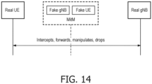
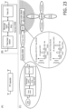
- MitM device System information broadcasted by a base station might be replayed, e.g., by means of a MitM device.
- MitM attackers There are different types of MitM attackers:
- Fig. 23 also shows a specific attack scenario using the stealthy MitM.
- the above attack can be mitigated if the gNB signs the SSB and the UE verifies it.
- the verification step might include checking the location where the SSB should be received.
- a secondary station may consider to lower a preference level of a primary station upon determination that said primary station may be unreliable. Said determination may include determining that the base station is switching on and off over a period of time.
- a UE should monitor the synchronization signals of gNBs following such a pattern and if such a pattern is detected, then the UE should deprioritize the gNB, in other words, decrease the preference of joining such a gNB even if its transmission power is suddenly much better once again.
- This detection algorithm might benefit of considering:
- a method for a secondary station to detect a suspect device in its vicinity comprises the secondary station detecting changes in a link characteristic from a target device over a time period, the secondary station determining the target device as suspicious if the changes in link characteristic are in discrepancy with the location of the secondary station over said time period.
- a secondary station including a receiver coupled to a controller adapted to detect changes in a link characteristic from a target device over a time period, the controller of the secondary station determining the target device as suspicious if the changes in link characteristic are in discrepancy with the location of the secondary station over said time period.
- the link characteristic is a strength of link with the target device.
- the secondary station reports to a known primary station the presence of the suspect device.
- the reporting may include a location estimate of the suspect device.
- the location parameter is determined by checking whether an encryption key used by the primary station corresponds to an encryption key allowed to be used locally.
- the signal is a configuration message from a primary station at a secondary station, and the configuration message includes at least a signature for authenticating the configuration message. In this case, the secondary station authenticates the configuration message by
- the Signature Generator's public-key may also be associated to certain rights of the private key, for instance, rights to sign System Information of base stations in certain location only.
- the secondary station next to checking the validity of the signature and the timing, the secondary station also has to check whether the private key used to create the signature has rights to be used in its current location. For instance, if a UE has the public key of a Chinese network operator and it detects a base station of requiring that key to verify SI of a base station when the UE is in the United States, then the UE should block that base station. This ensures that an attacker cannot, e.g., compromise the private key of an operator and use it to create fake base stations somewhere else. Similarly, multiple pairs of public-private keys can be used by a network operator, each pair associated to a different location. This limits the possibility of wide attacks.
- a cell scanning procedure could be extended to check the location-related signing rights of a private key (in the following pseudo code):
- Signature Generator uses multiple key pairs for different locations to reduce the impact in case of a security breach.
- the secondary station can check whether the correct key pair is used at its current location.
- a public-key e.g., is a public-key authorized to verify information at a given location, is a public-key authorized to verify SI from a given PLMN, etc
- Doing it before signature verification has the advantage of being faster and more energy efficient, similarly to the freshness verification.
- a key issue refers to the provisioning of the trust anchors in secondary stations.
- This refers to the public-keys used to verify the signed information.
- a first option consists in installing this information when the secondary station joins the core network for the first time. This means that the first connection might be prone to False Base Stations, but this danger goes away afterwards.
- This is a suitable solution if a single pair public-private key is used by an operator. But it becomes more difficult to use if the operator wants to use multiple key pairs, e.g., depending on the location. This also becomes an issue when the public-keys are only valid during a given period of time.
- the pair of public/private keys at the Signature Generator are not signed and are not embedded in a certificate, e.g., signed by a CA. This is a natural extension if it is desired that a secondary station can connect through primary station stations managed by multiple network operators.
- a second option consists in using identity-based signatures where the public-key depends on several known parameters including operator and location.
- the first parameters can be derived from information available in SIB1:
- PLMN identifier since it identifies the owner of the private key; location information such as the trackingAreaCode.
- location information such as the trackingAreaCode.
- this information could also be enhanced with location information (GPS coordinates) to better determine the location of the primary station and mobility aspects of the primary station: is it static or does its location change (e.g., if placed in a bus). Timing information is not included in the generation of the public-key since it is verified afterwards.
- PCI signed cell identifiers
- a secondary station might not be able to detect or receive the signal of a real base station.
- the attacker might use a False UE with a very sensitive/powerful antenna that allows it to get the signal of primary stations that are out of range from the secondary station. This is a so call range extension attack.
- the attacker might just jam the signal of the real base station at the secondary station.
- removing duplicated primary stations without further checks opens new ways to attack the multi-cell time synchronization method.
- a sixth embodiment thus proposes a solution that is much more robust.
- the Signature Generator signs the map between a primary station's SFN and the Signature Generator time.
- the secondary station's clock is in tight sync with the clock of the Signature Generator. If these pre-conditions are fulfilled, the secondary station receives signed system information from the primary station, verifies its signature, verifies the time, verifies the SFN values, and checks whether the broadcasted data has been broadcasted in the verified SFN values.
- a method for checking authenticity of configuration messages comprising receiving a configuration message from a primary station at a secondary station, wherein the configuration message includes
- it further includes authenticating the configuration message by
- the method may comprise
- the first configuration message may include a cryptographic key to be used to authenticate the received second signature.
- the first configuration message includes static configuration parameter values
- the second configuration message includes variable configuration parameter values.
- the first configuration message may have a first limited time validity, being equal to one of the following: the time required for the subframe numbering to span around its whole range of values, the time required for an hyperframe numbering to span around its whole range of values.
- the second configuration message may have a second limited time validity, being equal to one of the following: the time required for a predetermined number of the most significant bits of the subframe number to change, or the time required for the six most significant bits of the subframe number to change, or 160ms, or 80ms.
- the second signature may generated or verified by means of one of an ECDSA, a hash chain.
- Some aspects of the general idea of the sixth embodiment can lead to a high overhead on the Signature Generator, since it requires signing the dynamic System Frame Number fields of all primary stations. This means that the Signature Generator needs to sign many messages. This can be optimized, e.g., as follows:
- the secondary station receives from a primary station:
- This design is robust because it limits the validity of the signature of the static fields to around 10". This avoids the need of revocation lists. Moreover, it limits the validity of the current_dynamic_fields_public_key. Thus, it is possible to use a lightweight scheme.
- the MitM has the same SFN reference system as the real BS, then this requires changing the SFN fields in the MIB since it is transmitted later, and the verification fails therefore. If however the MitM does not change the SFN so that the signature can be verified, the FBS will need to use its on SFN reference time so that the SFN counters fit. But this will not match with the signed SFN_Reference_time. So the check in Eq. 1 will fail.
- the MitM node could wait 10.24 seconds to rebroadcast the information using the same SFN reference time, but this may not work if the signed static fields are valid for only this period of 10.24s.
- the base station will notice that the cryptographic CRC verification of the incoming messages from the UE fails at MAC layer. This gives an indication to the base station of the problem that can notify the UE, notify the network, and potentially close the communication.
- a base station might sign using the new short-term private key that might have just been replaced.
- a UE might need to perform two checks, one with the current short-term public-key of the base station that it has, and if this check fails, the UE will need to wait till the new signed short-term public-key is received, and then redo the check.
- the communication protocol may define data blocks on a link between the base station and the user device, while the data blocks comprise user data and checksum fields, and checksums for error detection in the user data in the data blocks.
- the user device may include a transceiver, a processor and an integrity unit for providing data integrity of the data blocks.
- the processor can be arranged to manage data transfer on the link to the base station using link data regarding a sequence of the data blocks across the link, the link data being different for each data block in the sequence. After a certain period in time, the link data may repeat, e.g. due to frame numbers using a limited number of bits. The data blocks in such a repetition period are considered a sequence of data blocks with respect to the integrity protection.
- the processor can be further arranged to obtain a secret integrity key that is shared with the base station.
- the integrity unit may be configured, for a respective data block, to cryptographically process, while using the secret integrity key, a combination of the checksum for a predetermined one of the checksum fields and a predetermined part of the link data. Then the cryptographically processed combination may be truncated to the length of the checksum as defined by the communication protocol if need be, and the truncated cryptographically processed combination, simply called truncated combination hereafter, is used for error detection and integrity protection. Thereto, the truncated combination is inserted in the predetermined one of the checksum fields before transmitting a data block and compared to a value in the predetermined one of the checksum fields after receiving a data block.
- the above features have the following effects.
- the truncated combination enables to detect transmission errors and integrity errors by performing the same cryptographic processing at the sender and the receiver side, and subsequently comparing the results at the receiving side.
- the truncated combination is inserted in a checksum field that originally contained the checksum, no additional bits are required for data transfer on the link when compared to a legacy communication system not having such integrity protection, while transmission errors are equally detected as the same checksum is used at the transmitting side and is recalculated at the receiving side.
- the communication protocol defines data blocks on a link between the base station and the user device.
- the data blocks have user data and checksum fields, while the checksums are for error detection in the user data in the data blocks.
- the cellular network provides wireless communication for mobile devices across at least a regional area.
- a user device has a transceiver arranged for transceiving according to the communication protocol, and a processor arranged to manage data transfer on the link to the base station using link data.
- the link data relates to a sequence of the data blocks that is transferred via the link.
- the link data is different for each data block in the sequence, while some parts may repeat for a subsequent sequence.
- Various examples of such link data have been presented above for an exemplary 3GPP system.
- a processor is further arranged to obtain a secret integrity key that is shared with the base station.
- Various mechanisms for establishing a secret key between two devices are known and may be used for securely exchanging such key data.
- Diffie-Hellman is a well-known technique for establishing a secret key between two parties, where the communication between the parties for establishing the secret key does not reveal any information to third parties on the established secret key.
- the two parties each use their own public/private key pair and exchange the public key with each other.
- Each party is able to compute the secret key using its own private key and the other party's public key and possibly some other information, e.g. a nonce (random number) from each party.
- Each party may generate a key pair anew each time it performs Diffie-Hellman or it reuses an older key pair.
- the user device may further have an integrity unit for providing data integrity of the data blocks, the integrity unit being arranged to perform the following processes for a respective data block.
- the integrity unit cryptographically processes, while using the secret integrity key, a combination of the checksum for a predetermined one of the checksum fields and a predetermined part of the link data.
- the cryptographic processing may, for example, be encryption or the application of a hash-based message authentication code (HMAC).
- HMAC hash-based message authentication code
- the checksum may be calculated as defined in the communication protocol, and may be concatenated with a block number or block address, and optionally further link data, i.e. a predetermined selection of link data that varies from block to block. Further such combination may include padding data or a salt.
- a salt is random data that is used as an additional input to a cryptographic function that "hashes" data, such as a password or passphrase. Salts are closely related to the concept of nonce. The primary function of salts is to defend against dictionary attacks or against its hashed equivalent, a pre-computed rainbow table attack. If padding data or a salt is used, the value has to be shared between the base station and the user device.
- the value to use may be defined in a specification, e.g. a 3GPP specification.
- the base station may also send the value to use to user devices in e.g. a System Information Block.
- the value to use may be the same for all user devices or different per user device.
- suitable varying link data are described below. So, a combination string of bits of a required length is formed to be cryptographically processed.
- the integrity unit truncates the cryptographically processed combination to the length of the checksum, which length is defined by the communication protocol.
- the truncated cryptographically processed combination now fits in the checksum field of the checksum as originally intended. For example, for a checksum field of n bits, truncation may be using the first n bits, the last n bits, or any predetermined selection or permutation of n bits of the cryptographically processed combination.
- the integrity unit uses the truncated combination for error detection and integrity protection by inserting the truncated combination in the predetermined one of the checksum fields before transmitting.
- the integrity unit uses the truncated combination by comparing a received value in the predetermined one of the checksum fields with the truncated combination as calculated on the received data and respective corresponding predetermined link data.
- the integrity of the data covered by the checksum is verified, while also ensuring that the data is without errors. Otherwise, even in the event of a single bit error or a single modified user data byte, the checksum would be different. Henceforth, the cryptographically processed combination will be very different.
- the method of this example is a method for a secondary station to obtain a time reference in a cellular network, the method comprising
- This example also includes to a secondary station comprising a transmitter and a receiver and a processor adapted to
- a MitM detection process immune to loose synchronization may involve, e.g., the use of a Cryptographic CRC for exchanged messages.
- This solution may require the same settings as in the DSnF solution including the fact that:
- C-CRC Cryptographic CRC
- Message 4 can be RRCSetupRequest.
- Message 9 can be NAS Securityy Mode Complete.
- Messages 7 include RRCSetupComplete and NAS handshake. Details can be specified during normative phase.
- the C-CRC solution replaces the standard CRC at MAC layer. This means that if there is a MitM forwarding, modifying, or injecting messages (step 7), those messages will be dropped by UE and gNB. The MitM does not have access to K, and thus, it cannot compute the C-CRC correctly.
- a variant of the previous example allows to reduce the risk of a downgrade attack, i.e. an attack simply based on the false pretends that a device is not compatible with the latest version of the protocol.
- This kind of attacks makes it abandon a high-quality mode of operation (e.g. an encrypted connection) in favor of an older, lower-quality mode of operation (e.g. cleartext) that is typically provided for backward compatibility with older systems.
- C-CRC MessageAuthenticationCodeComputation K , CRC
- MessageAuthenticationCodeComputation() is a function that returns a 24 bit message authentication code
- blockID refers to a unique identifier identifying the Physical resource blocks (RBs), i.e., the time and frequency physical resources, used to transmit the data at MAC layer.
- RBs Physical resource blocks
- Message 4 could be RRCSetupRequest; Message 5 could be RRCSetup; Message 6 could be RRCSetupComplete; Messages 9 might include the NAS handshake; Message 11 could be NAS Security Mode Complete. It is important to observe that the normal communication flow goes on as usual, with the only difference that C-CRC is active. Additionally, the MitM does not have access to K, and thus, it cannot compute the C-CRC correctly. Messages 4, 5, 6 ensure that the MitM cannot interfere in the activation of C-CRC.
- the C-CRC solution replaces the standard CRC at MAC layer. This means that if there is a MitM forwarding, modifying, or injecting messages (step 7), those messages will be dropped by UE and/or gNB. Not receiving messages in Step 7 means that message 9 will not be sent/received either, since the previous messages are missing, and thus, the timers Ta and Tb will timeout, and the UE joining procedure will be dropped.
- this solution achieves replay protection in all cases without requiring tight time synchronization, e.g., in the order of 1 or 2 miliseconds that would be required to avoid replay attacks in a reliable way.
- blocklD Frame
- this blocklD construction sets a maximum value for Tmax. If Tmax is required to be longer, then a different blocklD construction can be defined during normative phase.
- New BS Case IUE, nBS Legacy UE does not look into signature since legacy UE does not know that field or new SIB is present. Legacy UE does not send E(K,PK) in message 4, and thus, gNB does not activate C-CRC and does not send Hash(K) in message 4. As described with reference to Figure 16
- SIB1 has a small size (less than 3000 bits) limiting the amount of information that can be added, in particular, the size of a digital signature or digital certificate.
- a solution to this is a new variant in which a UE, after reception of MIB/SIB1, asks in a proactive for a SIB, SIB_S to be specified, containing the signature.
- SIB_S the UE can verify that SI is originating from a given base station by using the trust anchor that has been installed.
- the UE can also verify the public key (PK) of the base station.
- the UE uses this PK in step 4 as in above Figure triggering the rest of the protocol.
- Step 9 might consist of some pre-defined uplink and downlink messages.
- this public-key can be used for both signature verification (of the SI, as required in Step 2) and for public-key encryption (as required in Step 4). If the public-key for signature verification of Step 2 cannot be used for PKE, the certificate sent in the SIB should contain an additional gNB's public-key for PKE in Step 4.
- the static parameters instead of signing the static parameters for the duration of 2 ⁇ 10 frames, i.e., 10.24 s, or till the SFN wraps around, the static parameters can also be signed for the duration of 2h54'45.76", i.e., till SFN and HFN wrap around. This reduces further the overhead on the Signature Generator.
- the digital signing algorithm used to sign dynamic parameters can be based on a standard algorithm such as ECDSA but with a lower security level due to the short validity of the corresponding public-key. Alternatively, it can be a lightweight method, e.g., based on hash chains, Tesla.
- the proposed combination of signatures provides also a good solution towards quantum-resistant signatures.
- Digital signatures are bulky in either public-key or signature size.
- the solution of the sixth embodiment allows using a heavy digital signature with a relatively low frequency.
- the dynamic fields need to be signed much more frequently, and for this, hash-based solution, that is also quantum-resistant, is a good candidate.
- the signing of dynamic fields can be done in the Signature Generator (DSnF) fitting the current DSnF architecture. But it can also be outsourced to the primary stations since the DSnF is signing all critical fields, including the starting time for SFN.
- DSnF Signature Generator
- the gNB signs the dynamic fields: the overhead on the DSnF is lower, signed information is available for broadcast on time.
- a DSA may be used to sign the static information during a long_interval of time. This signs also the Hash Chain anchor used by the primary station to sign dynamic fields. When this is done, the DSA should also be used to sign the SFN_HFN_Reference_time.
- a good trade-off is to have the DSA signing the new HC anchor, SFN_HFN_Reference_time, ... HFN/SFN (2h54'45").
- An alternative is every SFN period (10.24 seconds) having the drawback that the DSnF has to handle much more data requests.
- the rest of SIBs/MIBs are protected with a HC-based approach that is managed by each primary station.
- the UE might be initially slightly out of sync or might not have the right time. If this happens and the UE has a slightly different time (e.g., 10 ms difference), the UE could only accept the message if it is received in 1,...,max_delay HFN/SFN later than expected. When this happens, the UE should start a secure time synchronization protocol with DSnF and check again whether the delays keep happening. If this is the case, the UE could be under a MitM relay node and should look for a different primary station.
- a slightly different time e.g. 10 ms difference
- the protection against replay attacks is achieved by checking the freshness of the messages.
- This freshness is linked to the DSnF time that is centrally managed and the SFN that is base station specific.
- a MitM attacker can act very fast, or that a certain system has to relax the time synchronization requirements. If this happens, the UE might receive two sets of system information with the same PCI and identical time. In this situation, an option is to reject both sets of SI and connect to a different base station.
- a UE can also choose an alternative mechanism, namely, in the event that a UE has received two or more sets of SI with identical PCI and time, then the UE will choose the one that was received first since this is the one that is less likely, if feasible at all, to have been replayed.
- a further step could comprise rejecting all duplicated SI messages.
- a further step comprises selecting the less recent SI message and rejecting the remaining SI messages.
- the cell scanning procedure to deal with FBS can include multiple optional steps as described below.
- the device accepts that BS.
- the device places that BS at the end of the preference list.
- the device discards that BS.
- the device marks them as duplicated and moves forward in the process to check their signature and time.
- UE tries to decode PBCH obtaining the MIB. Once UE successfully decoded PBCH, it tries to decode the PDCCH and PDSCH for RMSI and OSI.
- the UE discards the BS if the verification fails.
- the UE discards the BS if the private key signing the message is not allowed in the area where the UE is located.
- the UE can obtain the signed location of the BS that is also broadcasted in a SIB and the BS is rejected if the location does not match the location where the UE is placed.
- the Signature Generator has two public-key pairs to sign static and dynamic fields.
- the primary stations are the entities owning these two key pairs.
- one of the salient aspects is the need for synchronization between the various entities and in particular the primary station and the Signature Generator need to be synchronized, or they have to know the time difference.
- the primary station has to broadcast the information. But the primary station needs to know "when” to do so to make sure that the Signature Generator time broadcasted in the signed SI of multiple base stations is in sync. If it is not, this can lead to a situation in which a primary station has a clock that ticks faster (and thus, its time is higher).
- a secondary station will use this time as reference. This can lead to the situation in which a secondary station rejects valid primary stations, maybe with a better transmission power leading to better connectivity, because of this reason.
- the time is used avoid replay attacks, then it is important that the base station broadcasts accurate time. Otherwise, if the clock of a base station ticks faster (and then it is newer), it will broadcast the data a bit earlier, so that an attacker can replay the information.
- a MitM relay node might be in range of the target UE, but the target UE might be too far from the real base station. However, some UEs in the area are likely to listen to both the MitM relay node and the real base station. Those UEs could to report the excluded SI (because of duplicated PCI) to the core network, or a base station once connected, so that the core network assesses the presence of a fake base station. If the core network assessment is positive, the core network might decide to inform the affected base station and take further actions, e.g., switch it off for a limited period of time.
- MIB is not transmitted a single time, but multiple times, once per SSB.
- the reference time for SFN and MIB should be the time of the first SSB block received taking into account the half-frame bit.
- the time window for accepting a message can depend on the distance between UE and base station, e.g., if UE knows its location and the location of gNB. In this case, when a UE receives a MIB at a given location, the UE can look up the location of gNB with that PCI, compute distance, and set a time window for accepting a message that depends on that distance by taking into account that radio waves propagate at the speed of light.
- a method of a secondary station checking the validity of a System Information message from a primary station including checking the validity of the time of reception of the SI message, said step taking into account an estimate of a distance between the secondary station and the primary station.
- this estimate of a distance requires the preliminary step of computing the distance based on the location of the secondary station and the location of the primary station.
- the location of the primary station may be obtained from a centralized reference server detailing the location and identifiers of primary stations.
- a method of a secondary station checking the validity of a System Information message from a primary station including checking the validity of the time of reception of the SI message based on a time reference, wherein the time reference is adapted from a radiation beam (or SSB) index.
- SFN serves as a time counter that is directly linked to the schedule of the base station and thus, it has advantages to sign it and/or consider it when checking the freshness of the timestamp.
- t_w the allowed time window
- the timings for t_d are likely around 1 ms or a bit more.
- a method for signing consecutive messages comprising reusing a single signature for multiple consecutive messages, wherein each message also includes a timestamp, the method further comprising computing an actual transmission timestamp from the received timestamp before checking the validity of the message.
- Trust anchors should be linked to geographical areas. When a UE uses a trust anchor, the UE must check whether the trust anchor it is using is allowed in the location of the UE.
- Hash chains can be a good solution if the anchor is distributed from a central entity and gNBs use hash chains instances to protect data broadcasted by the gNB. This is a very suitable solution taking into account the synchronous nature of 5G and the delivery of MIB/SIB1 messages.
- SIB1 would contain a MAC computed with the undisclosed link of the hash chain and the hash chain link that lets UEs to verify the previously received SIB1/MAC.
- SIB2/SIB5 messages can be distributed on demand. When TESLA is applied to those messages, these messages include a MAC computed with the next non-disclosed hash chain element, that will be disclosed in the next SIB1 message.
- the hash chain fits very well with the SFN schedule, see comment (4) above.
- a general approach is that the UE uses timestamps from multiple gNBs to learn their time and find out whether it is out of sync. For this time consistency approach, it is required that gNBs are tightly synchronized. Furthermore, only timestamps whose signature has been verified must considered.
- a second approach is to use the most recent time or the average of the verified timestamps.
- a third approach for this to work is that a UE can request the current (DSnF/gNB) time. This is relevant is scenarios where UE's time may not be synchronized and/or there are too few gNBs around it. The UE sends request to DSnF and gets back current time.
- the policy might contain the minimum number of timestamps that are required to use as the current time the highest timestamp. For instance, if a UE only has access to a timestamp, the policy might indicate that the UE should use the third approach and retrieve the time from the base station. The policy can also include how frequently the time accuracy should be cross checked. This might be e.g., at least, once per hour. The policy might also allow to use timestamps gathered at different instants of time, e.g. within a time window of for example 10 minutes.
- the validation message is a hash of at least a subset of the received System Information messages.
- the validation message is sent by the secondary station to the primary station for verification over a secure channel.
- the validation message may be sent by the primary station to the secondary station for verification.
- the primary station might be a gNB or an network function in the core network.
- these solutions thus consist in the gNB providing the hash of the MIB/SIB/PCI to the UE after it has established an AS security context.
- the UE can compare the information provided by the gNB with the MIB/SIB/PCI previously received, and check whether they match. If they do not, then it sends an indication to the gNB.
- This is, e.g., described in TR 33.809-0c1, Solution 19.
- Figure 17 illustrates the protocol flow of a System information protection in Solution 19 in TR 33.809-0c1
- solution 14 in which the UE is the entity sending the hash of the received MIB/SIB to the gNB.
- the gNB is the party checking whether the information matches (equivalent to step 6 in above Figure 17 ).
- Solution 14 is like Solution 19 but with the roles of UE and gNB exchanged.
- the resulting protocol can successfully defeat the attack described in limitation a) above in which an attacker sets a fake beam with an additional SSB index and forwards through it the SIBs/MIBs/PCI of the real base station. This is so because the base station will inform the UE about the beam (SSB index) that it used for the communication (through the hash value). If attacker used a different beam, the SSB index will be different, and the hashes will not match. Furthermore, this protocol is efficient since only requires sending the hash of the last MIB sent before sending message 5. This reduces communication and computation overhead.
- TR 33.809 proposes to report the hash of MIB and SIB1 and other SIBs to enhance the measurement reports from the UEs as part of the extension of TS 33.501 appendix E.
- An example of such a solution is Solution #4 in TR33.809.
- the approach mentioned there has two drawbacks, which are also present in Solutions 14 and 19 in TR33.809.
- the first drawback is that Solution #4 requires computing the hash on the MIB/SIB1. But the MIB includes 6 (out of 10) bits of the SFN, the 6 SFN Most Significant Bits (MSBs). This will lead to 64 different "valid" hash values.
- a better alternative might consist in removing these 6 SFN bits from the MIB before computing the hash of MIB.
- the UE might report the hash of MIB/SIB1 AND the time when the MIB was measured. Note that the MIB only contains the 6 MSBs of the SFN and that each MIB is broadcasted multiple times, this can lead to a time uncertainty. To improve the time accuracy and allow the receiving party to discern which MIB the UE has received, the UE should report time when a new MIB was received, i.e., a MIB in which the 6 MSBs of the SFN differ from the 6 MSBs of the SFN in the previously received MIB. Alternatively, next to the time of the received MIB, the 4 LSBs of the SFN should be included.
- the network should then keep track of the MIB/SIB1 values used at a specific point of time by the real base station. This is feasible since the SFN repeats the values every 10.24 seconds.
- a base station informs the core network about the SFN value at time t0, and optionally transmits the 64 valid hash values for MIB/SIB1 or provide information for the core network to deduce by computation the 64 hash values, the core network will know which SFN value is used by the base station at any time t, and which hash value of MIB/SIB1 should be reported.
- 5G base stations can broadcast MIB/SIB1 through multiple beams pointing at different respective locations.
- the SSB index for each beam is included in the PBCH and identifies the beam.
- the UE When a UE reports the hash of MIB/SIB1, the UE might also include in the computation of the hash an identifier of the directional beam (for example the SSB index, or an indication of an angle representative of the direction) for which the measured signal has the highest received power, in other words, the directional beam the UE has used in the communication link with the cell. If the UE does so, then in the report to the base station including the received hash of MIB/SIB1, the UE can include its location and time when MIB/SIB were measured.
- an identifier of the directional beam for example the SSB index, or an indication of an angle representative of the direction
- the base station (and core network once the base station informs the core network) knows the radiation pattern (i.e., direction of beams) possibly as a function of time, for example in the case where the beams are not fully static, the base station knows that at time t, the beams were aimed in a specific direction. With this knowledge, the base station (and the core network) knows which directional beam a UE should have picked up at a given location and time. Then, the core network can check whether the hash of MIB/SIB1 reported by a UE for a given time/location fits the one that the UE should have measured.
- the radiation pattern i.e., direction of beams
- the core network might include a policy defining a temporal window wt and location window wl so that if the core network knows that at time t0 and location l0 a base station was using SFN_i and beam index Bi, then the core network might accept as valid the hash of MIB/SIB1 for (SFN_i-wt,..., SFN_i+wt) and B_i-wl,..., B_i+wl).
- solution #19 the gNB provides the UE with the hash of MIB/SIB.
- the gNB can provide the UE for example through a secure RRC message with information about the hash of MIB/SIB that the UE should have received at a given time or location. For instance:
- Solution #14 is as solution #19, but in this case, the UE reports to the gNB the hash of MIB/SIB1. Following above description for #19, the UE can report to gNB in a secure way:
- a remote UE can connect to a gNB via a relay UE.
- Some embodiments are applicable to prevent remote UEs from connecting to fake relay UEs or MitM devices placed between the remote UE and the actual relay UE.
- the components of this system include a secondary station, a Signature Generator and a primary station implementing one or more of the mentioned embodiments.
- the apparatus may be implemented by a program code means of a computer program and/or as dedicated hardware of the related devices, respectively.
- the computer program may be stored and/or distributed on a suitable medium, such as an optical storage medium or a solid-state medium, supplied together with or as part of other hardware, but may also be distributed in other forms, such as via the Internet or other wired or wireless telecommunication systems.
Landscapes
- Engineering & Computer Science (AREA)
- Computer Security & Cryptography (AREA)
- Computer Networks & Wireless Communication (AREA)
- Signal Processing (AREA)
- Computer Hardware Design (AREA)
- Computing Systems (AREA)
- General Engineering & Computer Science (AREA)
- Mobile Radio Communication Systems (AREA)
Claims (8)
- Verfahren, das von einer Sekundärstation durchgeführt wird, um eine Zeitreferenz in einem Mobilfunknetz zu erhalten, wobei das Verfahren Folgendes umfasstSenden einer Anfrage nach einer Zeitreferenz bei der ersten Verbindung mit dem Netzwerk, wobei diese Anfrage an einen Signaturgenerator gerichtet ist,wobei die Anforderung einer Zeitreferenz eine zufällig generierte Zahl enthält, die als Nonce verwendet wird, Empfangen der Zeitreferenz und der Nonce, wobei die Zeitreferenz und die Nonce mit einer Nonce-Signatur signiert werden,Verwendung von Nonce und Nonce-Signatur zur Überprüfung der Authentizität empfangener Nachrichten,Verwenden der empfangenen Zeitreferenz, um eine Uhr an der Sekundärstation zu konfigurieren;wobei das Verfahren weiterhin Folgendes umfasstEmpfangen mehrerer Systeminformationsnachrichten SI von mehreren Primärstationen, wobei die SI-Nachrichten jeweils eine entsprechende Zeitreferenzinformation enthalten, die sich auf die entsprechende Primärstation bezieht,Überprüfen der Gültigkeit einer empfangenen Signatur für jede der Primärstationen,Überprüfen einer Zellenkennung für jede der Primärstationen mit einer gültigen Signatur und Ignorieren von Zeitreferenzinformationen von Primärstationen, deren Zellkennung mit der einer anderen Primärstation identisch ist und einen früheren Wert als diejenige der anderen Primärstation aufweist, und Ableiten einer lokalen Zeitreferenz aus einer oder mehreren Zeitreferenzinformationen, die von Primärstationen mit einer gültigen Signatur stammen.
- Verfahren nach Anspruch 1, wobei die Zeitreferenzinformationen mindestens eine der folgenden Informationen sind: ein Zeitversatz, der die Differenz zwischen einem Uhrwert an der Primärstation und einem Uhrwert an einem Signaturgenerator des Netzwerks darstellt, eine Uhr Wert an der Primärstation, ein Taktwert am Signaturgenerator.
- Verfahren nach Anspruch 1 oder 2, wobei der Schritt des Ableitens einer lokalen Zeitreferenz das Berechnen eines Durchschnitts aus mehreren Zeitreferenzinformationen umfasst, die von Primärstationen mit einer gültigen Signatur und ohne doppelte Zellkennung mit früherer Zeit stammen.
- Verfahren nach Anspruch 1 oder 2, wobei der Schritt des Ableitens einer lokalen Zeitreferenz das Auswählen der Zeitreferenzinformationen mit dem neuesten Wert umfasst, der von Primärstationen mit einer gültigen Signatur stammt.
- Verfahren nach Anspruch 1, wobei die Anfrage Teil einer RRC-Setup-Anfragenachricht Initial Radio Resource Communication ist.
- Verfahren nach Anspruch 1, wobei die Anfrage Teil einer Network Access Stratum NAS-Identitätsantwortnachricht ist, die als Antwort auf eine NAS-Identitätsanfrage gesendet wird.
- Verfahren nach einem der vorherigen Ansprüche, wobei die empfangene Signatur unter Verwendung mindestens eines der folgenden Algorithmen überprüft wird: einem Public Key Infrastructure, PKI-Algorithmus, Boneh-Lynn-Shacham, BLS-Signaturalgorithmus, Boneh-Lynn-Shacham, BLS-Signaturalgorithmus, Gentry-Lynn-Shacham, BGLS, Signaturalgorithmus, Elliptic-Curve-Digital-SignaturAlgorithmus, ECDSA, Falcon-Signaturalgorithmus, Rainbow-Signaturalgorithmus, Great Multivariate Short Signature, GeMSS, Algorithmus.
- Sekundärstation, die zur Kommunikation in einem Netzwerk geeignet ist, wobei die Sekundärstation Folgendes umfassteinen Sender, der so konfiguriert ist, dass er bei der ersten Verbindung mit dem Netzwerk eine Anfrage nach einer Zeitreferenz sendet, wobei die Anfrage an einen Signaturgenerator gerichtet ist, wobei die Anfrage nach einer Zeitreferenz eine zufällig generierte Zahl enthält, die als Nonce verwendet wird,einen Empfänger, der dafür ausgelegt ist, die Zeitreferenz und die Nonce zu empfangen, wobei die Zeitreferenz und die Nonce mit einer Nonce-Signatur signiert sind,einen Controller, der so konfiguriert ist, dass er die Nonce und Nonce-Signatur verwendet, um die Authentizität empfangener Nachrichten zu überprüfen, und die empfangene Zeitreferenz verwendet, um eine Uhr an der Sekundärstation zu konfigurieren,wobei der Empfänger außerdem dafür ausgelegt ist, mehrere Systeminformationsnachrichten SI von mehreren Primärstationen zu empfangen, wobei die SI-Nachrichten jeweils eine entsprechende Zeitreferenzinformation in Bezug auf die entsprechende Primärstation enthalten, wobei der Controller so konfiguriert ist, dass er die Gültigkeit einer empfangenen Signatur für jede der Primärstationen prüft und eine Zellkennung zumindest für jede der Primärstationen mit einer gültigen Signatur prüft und Zeitreferenzinformationen von Primärstationen mit einer Zellkennung ignoriert mit einer anderen Primärstation identisch sein und einen früheren Wert haben als der Wert der anderen Primärstation, undwobei der Controller so ausgelegt ist, dass er aus einer oder mehreren der Zeitreferenzinformationen, die von Primärstationen mit einer gültigen Signatur stammen, eine lokale Zeitreferenz ableitet.
Applications Claiming Priority (13)
| Application Number | Priority Date | Filing Date | Title |
|---|---|---|---|
| EP20189373.2A EP3952239A1 (de) | 2020-08-04 | 2020-08-04 | Verfahren und vorrichtung zur authentifizierung einer basisstation |
| EP20199594 | 2020-10-01 | ||
| EP20201320 | 2020-10-12 | ||
| EP20201744 | 2020-10-14 | ||
| EP21150371 | 2021-01-06 | ||
| EP21150643 | 2021-01-08 | ||
| EP21150840 | 2021-01-11 | ||
| EP21151731 | 2021-01-15 | ||
| EP21162091 | 2021-03-11 | ||
| EP21172331 | 2021-05-05 | ||
| EP21176514 | 2021-05-28 | ||
| EP21178146 | 2021-06-08 | ||
| PCT/EP2021/071708 WO2022029149A1 (en) | 2020-08-04 | 2021-08-04 | Method and device for authenticating a primary station |
Publications (3)
| Publication Number | Publication Date |
|---|---|
| EP4193570A1 EP4193570A1 (de) | 2023-06-14 |
| EP4193570C0 EP4193570C0 (de) | 2024-05-29 |
| EP4193570B1 true EP4193570B1 (de) | 2024-05-29 |
Family
ID=77338670
Family Applications (1)
| Application Number | Title | Priority Date | Filing Date |
|---|---|---|---|
| EP21754980.7A Active EP4193570B1 (de) | 2020-08-04 | 2021-08-04 | Verfahren und vorrichtung zur authentifizierung einer basisstation |
Country Status (7)
| Country | Link |
|---|---|
| US (1) | US20230308877A1 (de) |
| EP (1) | EP4193570B1 (de) |
| JP (1) | JP7550960B2 (de) |
| CN (1) | CN116325847A (de) |
| ES (1) | ES2984817T3 (de) |
| PL (1) | PL4193570T3 (de) |
| WO (1) | WO2022029149A1 (de) |
Families Citing this family (16)
| Publication number | Priority date | Publication date | Assignee | Title |
|---|---|---|---|---|
| US11985552B2 (en) * | 2019-06-17 | 2024-05-14 | Apple Inc. | Methods of detecting fake base station by UE during handover |
| US11973755B1 (en) * | 2021-07-30 | 2024-04-30 | Wells Fargo Bank, N.A. | Apparatuses, methods, and computer program products for offline authentication |
| US12335733B1 (en) * | 2021-08-02 | 2025-06-17 | Satelles, Inc. | Wireless signal validation using a one-way function and an initially unknown input |
| US11947642B1 (en) | 2021-08-17 | 2024-04-02 | Wells Fargo Bank, N.A. | Apparatuses, methods, and computer program products for proactive offline authentication |
| US20230088197A1 (en) * | 2021-09-22 | 2023-03-23 | Argo AI, LLC | Systems, Methods, and Computer Program Products for Blockchain Secured Code Signing of Autonomous Vehicle Software Artifacts |
| GB2611293B (en) * | 2021-09-24 | 2025-07-30 | British Telecomm | Computer-implemented validation methods and systems |
| US12082135B2 (en) * | 2021-10-25 | 2024-09-03 | Lenovo (Singapore) Pte. Ltd. | Repeater configuration for initial access |
| KR102776488B1 (ko) * | 2021-12-30 | 2025-03-06 | 국립부경대학교 산학협력단 | 해시함수가 적용된 메시지 체인 기반 can 보안 장치 및 방법 |
| US20230309010A1 (en) * | 2022-03-22 | 2023-09-28 | Mediatek Inc. | Ultrafast Cell Selection In A Wireless Device |
| US20230353383A1 (en) * | 2022-04-29 | 2023-11-02 | Nxp B.V. | Partial key storage of binary-tree based cryptography |
| CN115086955B (zh) * | 2022-05-17 | 2024-07-30 | 中国科学院沈阳自动化研究所 | 面向工控系统的无线半双工通信的时间同步系统及方法 |
| CN117675213A (zh) * | 2022-08-26 | 2024-03-08 | 维沃移动通信有限公司 | 系统信息传输方法、装置、终端、网络侧设备及介质 |
| EP4602850A1 (de) * | 2022-10-14 | 2025-08-20 | Koninklijke Philips N.V. | Verfahren und vorrichtung zur authentifizierung einer primärstation |
| WO2024086995A1 (zh) * | 2022-10-24 | 2024-05-02 | 华为技术有限公司 | 广播消息保护方法及相关装置 |
| US12457546B2 (en) * | 2022-12-12 | 2025-10-28 | Qualcomm Incorporated | Freshness window for system information block and signature |
| WO2025230480A1 (en) * | 2024-04-29 | 2025-11-06 | Telefonaktiebolaget Lm Ericsson (Publ) | Communication device and method for determining |
Family Cites Families (7)
| Publication number | Priority date | Publication date | Assignee | Title |
|---|---|---|---|---|
| CN103117846B (zh) * | 2012-12-31 | 2016-01-13 | 华为技术有限公司 | 传输数据的方法、设备和系统 |
| US9853949B1 (en) * | 2013-04-19 | 2017-12-26 | Amazon Technologies, Inc. | Secure time service |
| US10306470B2 (en) * | 2016-04-06 | 2019-05-28 | Samsung Electronics Co., Ltd. | System and method for validating authenticity of base station and/or information received from base station |
| JP2018046349A (ja) * | 2016-09-13 | 2018-03-22 | 沖電気工業株式会社 | 通信システム、時刻同期方法、通信装置、及び通信プログラム |
| WO2018140204A1 (en) * | 2017-01-30 | 2018-08-02 | Intel IP Corporation | Fake gnb/enb detection using identity-based authentication and encryption |
| US12439350B2 (en) * | 2019-07-30 | 2025-10-07 | Ntt Docomo, Inc. | Terminal and communication node |
| EP3815428B1 (de) * | 2019-08-14 | 2025-05-07 | Nokia Solutions and Networks Oy | Verbesserte systeminformationsbereitstellung |
-
2021
- 2021-08-04 PL PL21754980.7T patent/PL4193570T3/pl unknown
- 2021-08-04 ES ES21754980T patent/ES2984817T3/es active Active
- 2021-08-04 EP EP21754980.7A patent/EP4193570B1/de active Active
- 2021-08-04 US US18/018,897 patent/US20230308877A1/en active Pending
- 2021-08-04 JP JP2023507647A patent/JP7550960B2/ja active Active
- 2021-08-04 CN CN202180067950.4A patent/CN116325847A/zh active Pending
- 2021-08-04 WO PCT/EP2021/071708 patent/WO2022029149A1/en not_active Ceased
Also Published As
| Publication number | Publication date |
|---|---|
| ES2984817T3 (es) | 2024-10-31 |
| CN116325847A (zh) | 2023-06-23 |
| EP4193570C0 (de) | 2024-05-29 |
| JP7550960B2 (ja) | 2024-09-13 |
| PL4193570T3 (pl) | 2024-08-05 |
| JP2023536926A (ja) | 2023-08-30 |
| WO2022029149A1 (en) | 2022-02-10 |
| US20230308877A1 (en) | 2023-09-28 |
| EP4193570A1 (de) | 2023-06-14 |
Similar Documents
| Publication | Publication Date | Title |
|---|---|---|
| EP4193570B1 (de) | Verfahren und vorrichtung zur authentifizierung einer basisstation | |
| Hussain et al. | Insecure connection bootstrapping in cellular networks: the root of all evil | |
| US10200861B2 (en) | Verification of cell authenticity in a wireless network using a system query | |
| Cao et al. | A simple and robust handover authentication between HeNB and eNB in LTE networks | |
| US20180278625A1 (en) | Exchanging message authentication codes for additional security in a communication system | |
| EP1957824B1 (de) | Verteidigung gegen interne angriffe zur netzwerkclient-validierung von netzwerkverwaltungsrahmen | |
| KR20220082836A (ko) | 무선 네트워크에서 기지국이 제뉴인인지 루즈인지 결정하기 위한 방법 및 사용자 단말 | |
| US20160295409A1 (en) | Wireless network fast authentication / association using re-association object | |
| US12207091B1 (en) | Systems and methods for protecting cellular network messages | |
| KR20160012161A (ko) | 메시지 인증을 갖는 wlan 메시지들을 브로드캐스트하기 위한 시스템들 및 방법들 | |
| WO2019227869A1 (en) | System and method for obtaining time synchronization | |
| EP3912381A1 (de) | Verfahren, netzknoten und drahtlose vorrichtung zur verifizierung von rundfunknachrichten | |
| WO2022144410A1 (en) | Enhanced mechanism for detecting fake base station attacks | |
| Martignon et al. | Design and implementation of MobiSEC: A complete security architecture for wireless mesh networks | |
| EP3952239A1 (de) | Verfahren und vorrichtung zur authentifizierung einer basisstation | |
| US12137176B1 (en) | Systems and methods for protecting network broadcast messages | |
| US12309281B1 (en) | Systems and methods for protecting cellular network messages | |
| Li et al. | Precheck sequence based false base station detection during handover: A physical layer security scheme | |
| Yan et al. | An efficient anonymous group handover authentication protocol for mtc devices for 5g networks | |
| KR101222619B1 (ko) | 무선 메쉬 네트워크의 데이터 인증 방법 및 장치 | |
| KR100611577B1 (ko) | 복합 기능 이동 단말기에서의 인증 방법 및 이를 이용한이동 단말기 | |
| WO2024079155A1 (en) | Method and device for authenticating a primary station | |
| CN119948902A (zh) | 广播消息保护方法及相关装置 | |
| Baras et al. | Efficient source authentication for multicasting in MANETs | |
| Nguyen et al. | Key management for lightweight ad-hoc routing authentication |
Legal Events
| Date | Code | Title | Description |
|---|---|---|---|
| STAA | Information on the status of an ep patent application or granted ep patent |
Free format text: STATUS: UNKNOWN |
|
| STAA | Information on the status of an ep patent application or granted ep patent |
Free format text: STATUS: THE INTERNATIONAL PUBLICATION HAS BEEN MADE |
|
| PUAI | Public reference made under article 153(3) epc to a published international application that has entered the european phase |
Free format text: ORIGINAL CODE: 0009012 |
|
| STAA | Information on the status of an ep patent application or granted ep patent |
Free format text: STATUS: REQUEST FOR EXAMINATION WAS MADE |
|
| 17P | Request for examination filed |
Effective date: 20230306 |
|
| AK | Designated contracting states |
Kind code of ref document: A1 Designated state(s): AL AT BE BG CH CY CZ DE DK EE ES FI FR GB GR HR HU IE IS IT LI LT LU LV MC MK MT NL NO PL PT RO RS SE SI SK SM TR |
|
| DAV | Request for validation of the european patent (deleted) | ||
| DAX | Request for extension of the european patent (deleted) | ||
| GRAP | Despatch of communication of intention to grant a patent |
Free format text: ORIGINAL CODE: EPIDOSNIGR1 |
|
| STAA | Information on the status of an ep patent application or granted ep patent |
Free format text: STATUS: GRANT OF PATENT IS INTENDED |
|
| INTG | Intention to grant announced |
Effective date: 20240105 |
|
| GRAS | Grant fee paid |
Free format text: ORIGINAL CODE: EPIDOSNIGR3 |
|
| GRAA | (expected) grant |
Free format text: ORIGINAL CODE: 0009210 |
|
| STAA | Information on the status of an ep patent application or granted ep patent |
Free format text: STATUS: THE PATENT HAS BEEN GRANTED |
|
| AK | Designated contracting states |
Kind code of ref document: B1 Designated state(s): AL AT BE BG CH CY CZ DE DK EE ES FI FR GB GR HR HU IE IS IT LI LT LU LV MC MK MT NL NO PL PT RO RS SE SI SK SM TR |
|
| REG | Reference to a national code |
Ref country code: CH Ref legal event code: EP |
|
| REG | Reference to a national code |
Ref country code: IE Ref legal event code: FG4D |
|
| REG | Reference to a national code |
Ref country code: DE Ref legal event code: R096 Ref document number: 602021013897 Country of ref document: DE |
|
| U01 | Request for unitary effect filed |
Effective date: 20240529 |
|
| U07 | Unitary effect registered |
Designated state(s): AT BE BG DE DK EE FI FR IT LT LU LV MT NL PT SE SI Effective date: 20240605 |
|
| PG25 | Lapsed in a contracting state [announced via postgrant information from national office to epo] |
Ref country code: IS Free format text: LAPSE BECAUSE OF FAILURE TO SUBMIT A TRANSLATION OF THE DESCRIPTION OR TO PAY THE FEE WITHIN THE PRESCRIBED TIME-LIMIT Effective date: 20240929 |
|
| PG25 | Lapsed in a contracting state [announced via postgrant information from national office to epo] |
Ref country code: HR Free format text: LAPSE BECAUSE OF FAILURE TO SUBMIT A TRANSLATION OF THE DESCRIPTION OR TO PAY THE FEE WITHIN THE PRESCRIBED TIME-LIMIT Effective date: 20240529 |
|
| PG25 | Lapsed in a contracting state [announced via postgrant information from national office to epo] |
Ref country code: GR Free format text: LAPSE BECAUSE OF FAILURE TO SUBMIT A TRANSLATION OF THE DESCRIPTION OR TO PAY THE FEE WITHIN THE PRESCRIBED TIME-LIMIT Effective date: 20240830 |
|
| U20 | Renewal fee for the european patent with unitary effect paid |
Year of fee payment: 4 Effective date: 20240905 |
|
| PG25 | Lapsed in a contracting state [announced via postgrant information from national office to epo] |
Ref country code: NO Free format text: LAPSE BECAUSE OF FAILURE TO SUBMIT A TRANSLATION OF THE DESCRIPTION OR TO PAY THE FEE WITHIN THE PRESCRIBED TIME-LIMIT Effective date: 20240829 Ref country code: IS Free format text: LAPSE BECAUSE OF FAILURE TO SUBMIT A TRANSLATION OF THE DESCRIPTION OR TO PAY THE FEE WITHIN THE PRESCRIBED TIME-LIMIT Effective date: 20240929 Ref country code: HR Free format text: LAPSE BECAUSE OF FAILURE TO SUBMIT A TRANSLATION OF THE DESCRIPTION OR TO PAY THE FEE WITHIN THE PRESCRIBED TIME-LIMIT Effective date: 20240529 Ref country code: GR Free format text: LAPSE BECAUSE OF FAILURE TO SUBMIT A TRANSLATION OF THE DESCRIPTION OR TO PAY THE FEE WITHIN THE PRESCRIBED TIME-LIMIT Effective date: 20240830 Ref country code: RS Free format text: LAPSE BECAUSE OF FAILURE TO SUBMIT A TRANSLATION OF THE DESCRIPTION OR TO PAY THE FEE WITHIN THE PRESCRIBED TIME-LIMIT Effective date: 20240829 |
|
| REG | Reference to a national code |
Ref country code: ES Ref legal event code: FG2A Ref document number: 2984817 Country of ref document: ES Kind code of ref document: T3 Effective date: 20241031 |
|
| PG25 | Lapsed in a contracting state [announced via postgrant information from national office to epo] |
Ref country code: CZ Free format text: LAPSE BECAUSE OF FAILURE TO SUBMIT A TRANSLATION OF THE DESCRIPTION OR TO PAY THE FEE WITHIN THE PRESCRIBED TIME-LIMIT Effective date: 20240529 |
|
| PG25 | Lapsed in a contracting state [announced via postgrant information from national office to epo] |
Ref country code: RO Free format text: LAPSE BECAUSE OF FAILURE TO SUBMIT A TRANSLATION OF THE DESCRIPTION OR TO PAY THE FEE WITHIN THE PRESCRIBED TIME-LIMIT Effective date: 20240529 Ref country code: SK Free format text: LAPSE BECAUSE OF FAILURE TO SUBMIT A TRANSLATION OF THE DESCRIPTION OR TO PAY THE FEE WITHIN THE PRESCRIBED TIME-LIMIT Effective date: 20240529 |
|
| PG25 | Lapsed in a contracting state [announced via postgrant information from national office to epo] |
Ref country code: SM Free format text: LAPSE BECAUSE OF FAILURE TO SUBMIT A TRANSLATION OF THE DESCRIPTION OR TO PAY THE FEE WITHIN THE PRESCRIBED TIME-LIMIT Effective date: 20240529 |
|
| PG25 | Lapsed in a contracting state [announced via postgrant information from national office to epo] |
Ref country code: SM Free format text: LAPSE BECAUSE OF FAILURE TO SUBMIT A TRANSLATION OF THE DESCRIPTION OR TO PAY THE FEE WITHIN THE PRESCRIBED TIME-LIMIT Effective date: 20240529 Ref country code: SK Free format text: LAPSE BECAUSE OF FAILURE TO SUBMIT A TRANSLATION OF THE DESCRIPTION OR TO PAY THE FEE WITHIN THE PRESCRIBED TIME-LIMIT Effective date: 20240529 Ref country code: RO Free format text: LAPSE BECAUSE OF FAILURE TO SUBMIT A TRANSLATION OF THE DESCRIPTION OR TO PAY THE FEE WITHIN THE PRESCRIBED TIME-LIMIT Effective date: 20240529 Ref country code: CZ Free format text: LAPSE BECAUSE OF FAILURE TO SUBMIT A TRANSLATION OF THE DESCRIPTION OR TO PAY THE FEE WITHIN THE PRESCRIBED TIME-LIMIT Effective date: 20240529 |
|
| REG | Reference to a national code |
Ref country code: CH Ref legal event code: PL |
|
| PLBE | No opposition filed within time limit |
Free format text: ORIGINAL CODE: 0009261 |
|
| STAA | Information on the status of an ep patent application or granted ep patent |
Free format text: STATUS: NO OPPOSITION FILED WITHIN TIME LIMIT |
|
| PG25 | Lapsed in a contracting state [announced via postgrant information from national office to epo] |
Ref country code: MC Free format text: LAPSE BECAUSE OF FAILURE TO SUBMIT A TRANSLATION OF THE DESCRIPTION OR TO PAY THE FEE WITHIN THE PRESCRIBED TIME-LIMIT Effective date: 20240529 Ref country code: CH Free format text: LAPSE BECAUSE OF NON-PAYMENT OF DUE FEES Effective date: 20240831 |
|
| 26N | No opposition filed |
Effective date: 20250303 |
|
| PG25 | Lapsed in a contracting state [announced via postgrant information from national office to epo] |
Ref country code: IE Free format text: LAPSE BECAUSE OF NON-PAYMENT OF DUE FEES Effective date: 20240804 |
|
| U20 | Renewal fee for the european patent with unitary effect paid |
Year of fee payment: 5 Effective date: 20250901 |
|
| PGFP | Annual fee paid to national office [announced via postgrant information from national office to epo] |
Ref country code: ES Payment date: 20250916 Year of fee payment: 5 |
|
| PGFP | Annual fee paid to national office [announced via postgrant information from national office to epo] |
Ref country code: TR Payment date: 20250723 Year of fee payment: 5 Ref country code: PL Payment date: 20250728 Year of fee payment: 5 |
|
| PGFP | Annual fee paid to national office [announced via postgrant information from national office to epo] |
Ref country code: GB Payment date: 20250826 Year of fee payment: 5 |
|
| PG25 | Lapsed in a contracting state [announced via postgrant information from national office to epo] |
Ref country code: CY Free format text: LAPSE BECAUSE OF FAILURE TO SUBMIT A TRANSLATION OF THE DESCRIPTION OR TO PAY THE FEE WITHIN THE PRESCRIBED TIME-LIMIT; INVALID AB INITIO Effective date: 20210804 |
|
| PG25 | Lapsed in a contracting state [announced via postgrant information from national office to epo] |
Ref country code: HU Free format text: LAPSE BECAUSE OF FAILURE TO SUBMIT A TRANSLATION OF THE DESCRIPTION OR TO PAY THE FEE WITHIN THE PRESCRIBED TIME-LIMIT; INVALID AB INITIO Effective date: 20210804 |