EP4192096B1 - Verfahren und vorrichtung zur anzeige eines bandbreitenmodus - Google Patents
Verfahren und vorrichtung zur anzeige eines bandbreitenmodus Download PDFInfo
- Publication number
- EP4192096B1 EP4192096B1 EP21852429.6A EP21852429A EP4192096B1 EP 4192096 B1 EP4192096 B1 EP 4192096B1 EP 21852429 A EP21852429 A EP 21852429A EP 4192096 B1 EP4192096 B1 EP 4192096B1
- Authority
- EP
- European Patent Office
- Prior art keywords
- bandwidth mode
- field
- frame
- mhz
- bandwidth
- Prior art date
- Legal status (The legal status is an assumption and is not a legal conclusion. Google has not performed a legal analysis and makes no representation as to the accuracy of the status listed.)
- Active
Links
Images

Classifications
-
- H—ELECTRICITY
- H04—ELECTRIC COMMUNICATION TECHNIQUE
- H04W—WIRELESS COMMUNICATION NETWORKS
- H04W28/00—Network traffic management; Network resource management
- H04W28/16—Central resource management; Negotiation of resources or communication parameters, e.g. negotiating bandwidth or QoS [Quality of Service]
- H04W28/18—Negotiating wireless communication parameters
- H04W28/20—Negotiating bandwidth
-
- H—ELECTRICITY
- H04—ELECTRIC COMMUNICATION TECHNIQUE
- H04L—TRANSMISSION OF DIGITAL INFORMATION, e.g. TELEGRAPHIC COMMUNICATION
- H04L5/00—Arrangements affording multiple use of the transmission path
- H04L5/0091—Signalling for the administration of the divided path, e.g. signalling of configuration information
- H04L5/0096—Indication of changes in allocation
- H04L5/0098—Signalling of the activation or deactivation of component carriers, subcarriers or frequency bands
-
- H—ELECTRICITY
- H04—ELECTRIC COMMUNICATION TECHNIQUE
- H04L—TRANSMISSION OF DIGITAL INFORMATION, e.g. TELEGRAPHIC COMMUNICATION
- H04L27/00—Modulated-carrier systems
- H04L27/26—Systems using multi-frequency codes
- H04L27/2601—Multicarrier modulation systems
- H04L27/2602—Signal structure
-
- H—ELECTRICITY
- H04—ELECTRIC COMMUNICATION TECHNIQUE
- H04L—TRANSMISSION OF DIGITAL INFORMATION, e.g. TELEGRAPHIC COMMUNICATION
- H04L27/00—Modulated-carrier systems
- H04L27/26—Systems using multi-frequency codes
- H04L27/2601—Multicarrier modulation systems
- H04L27/2602—Signal structure
- H04L27/2603—Signal structure ensuring backward compatibility with legacy system
-
- H—ELECTRICITY
- H04—ELECTRIC COMMUNICATION TECHNIQUE
- H04L—TRANSMISSION OF DIGITAL INFORMATION, e.g. TELEGRAPHIC COMMUNICATION
- H04L5/00—Arrangements affording multiple use of the transmission path
- H04L5/003—Arrangements for allocating sub-channels of the transmission path
- H04L5/0048—Allocation of pilot signals, i.e. of signals known to the receiver
-
- H—ELECTRICITY
- H04—ELECTRIC COMMUNICATION TECHNIQUE
- H04L—TRANSMISSION OF DIGITAL INFORMATION, e.g. TELEGRAPHIC COMMUNICATION
- H04L5/00—Arrangements affording multiple use of the transmission path
- H04L5/003—Arrangements for allocating sub-channels of the transmission path
- H04L5/0058—Allocation criteria
- H04L5/0064—Rate requirement of the data, e.g. scalable bandwidth, data priority
-
- H—ELECTRICITY
- H04—ELECTRIC COMMUNICATION TECHNIQUE
- H04L—TRANSMISSION OF DIGITAL INFORMATION, e.g. TELEGRAPHIC COMMUNICATION
- H04L5/00—Arrangements affording multiple use of the transmission path
- H04L5/0091—Signalling for the administration of the divided path, e.g. signalling of configuration information
- H04L5/0092—Indication of how the channel is divided
-
- H—ELECTRICITY
- H04—ELECTRIC COMMUNICATION TECHNIQUE
- H04W—WIRELESS COMMUNICATION NETWORKS
- H04W72/00—Local resource management
- H04W72/04—Wireless resource allocation
- H04W72/044—Wireless resource allocation based on the type of the allocated resource
- H04W72/0457—Variable allocation of band or rate
-
- H—ELECTRICITY
- H04—ELECTRIC COMMUNICATION TECHNIQUE
- H04W—WIRELESS COMMUNICATION NETWORKS
- H04W84/00—Network topologies
- H04W84/02—Hierarchically pre-organised networks, e.g. paging networks, cellular networks, WLAN [Wireless Local Area Network] or WLL [Wireless Local Loop]
- H04W84/10—Small scale networks; Flat hierarchical networks
- H04W84/12—WLAN [Wireless Local Area Networks]
-
- H—ELECTRICITY
- H04—ELECTRIC COMMUNICATION TECHNIQUE
- H04L—TRANSMISSION OF DIGITAL INFORMATION, e.g. TELEGRAPHIC COMMUNICATION
- H04L5/00—Arrangements affording multiple use of the transmission path
- H04L5/0001—Arrangements for dividing the transmission path
- H04L5/0003—Two-dimensional division
- H04L5/0005—Time-frequency
- H04L5/0007—Time-frequency the frequencies being orthogonal, e.g. OFDM(A) or DMT
-
- H—ELECTRICITY
- H04—ELECTRIC COMMUNICATION TECHNIQUE
- H04W—WIRELESS COMMUNICATION NETWORKS
- H04W72/00—Local resource management
- H04W72/04—Wireless resource allocation
- H04W72/044—Wireless resource allocation based on the type of the allocated resource
- H04W72/0453—Resources in frequency domain, e.g. a carrier in FDMA
Definitions
- This application relates to the field of communication technologies, and in particular, to a bandwidth mode indication method and apparatus.
- a transmit end and a receive end are located in different radio channel environments. Therefore, it is very conducive for data communication if a bandwidth available to both the transmit end and the receive end can be negotiated based on channel availability of the transmit end and the receive end before data communication.
- two bits namely, a B5 bit and a B6 bit
- a scrambling sequence scrambling sequence
- non-high throughput non-high throughput, non-HT
- a non-HT duplicated (duplicated) frame are used to indicate bandwidth modes.
- Four values of the two bits one-to-one correspond to four bandwidth modes.
- the four bandwidth modes are 20 MHz, 40 MHz, 80 MHz, and 160 MHz (or 80+80 MHz).
- the Institute of Electrical and Electronics Engineers (institute of electrical and electronics engineers, IEEE) is discussing the next-generation 802.11be standard after the 802.11ax.
- the 802.11be standard supports data transmission with an extremely high throughput (extremely high throughput, EHT).
- EHT extremely high throughput
- the 802.11be standard supports a maximum transmission bandwidth of 320 MHz. Therefore, the 802.11be standard introduces bandwidth modes other than 20 MHz, 40 MHz, 80 MHz, and 80+80 MHz or 160 MHz, such as 320 MHz.
- bandwidth modes other than 20 MHz, 40 MHz, 80 MHz, and 80+80 MHz or 160 MHz are introduced, how two devices negotiate a bandwidth mode is a technical problem to be urgently resolved.
- FIG. 19 illustrates a service field bit assignment, including scrambler initialization, reserved service bits, R: reserved, and transmit order.
- the bits 0 through 6 may be used to encode the bandwidth information and an indication if static or dynamic bandwidth operation is supported.
- EHT RTS and CTS procedure IEEE 802.11-19/2125r2, discusses EHT PHY Support in MAC. 802.11be needs to define the MU-RTS/ RTS and CTS frames sent in a non-HT duplicate PPDU with preamble puncturing.
- This application provides a bandwidth mode indication method and apparatus, so that in a scenario in which other bandwidth modes other than 20 MHz, 40 MHz, 80 MHz, and 160 MHz (or 80+80 MHz) are introduced, two devices can normally negotiate a bandwidth mode.
- a bandwidth mode indication method includes: A transmit end generates a first frame, where the first frame is a non-HT frame or a non-HT duplicated frame, the first frame includes a service field, the service field includes a first field, the first field indicates whether a bandwidth mode indication field carried in the first frame indicates a target bandwidth mode, and the target bandwidth mode includes one or more of bandwidth modes other than 20 MHz, 40 MHz, 80 MHz, and 80+80 MHz or 160 MHz; and then the transmit end sends the first frame to a receive end.
- the first frame uses only at least one bit in the service field as the first field, and does not increase or decrease a bit in the service field. In this way, backward compatibility of the first frame is ensured.
- the first field indicates whether the bandwidth mode indication field carried in the first frame is allowed to indicate the target bandwidth mode.
- the bandwidth mode indication field carried in the first frame extends a range of bandwidth modes that can be indicated. Therefore, in a scenario in which other bandwidth modes other than 20 MHz, 40 MHz, 80 MHz, and 80+80 MHz or 160 MHz are introduced, two devices can negotiate, by transmitting the first frame, to use one bandwidth mode from more bandwidth modes.
- the first field is located in the service field of the first frame has the following advantages: (1) Currently, a reserved bit in a media access control (media access control, MAC) frame may be used by a chip vendor as a private indication bit. Therefore, if the reserved bit in the MAC frame is used as the first field, indication of the private bit is affected. However, using the bit in the service field as the first field can avoid affecting private use of the reserved bit in the MAC frame by the chip vendor. (2) Reserved bits in MAC frames of different types of conventional frames do not necessarily have the same location. Therefore, for the different types of transmission frames, implementation solutions of using the reserved bits in the MAC frames as the first field are different.
- MAC media access control
- the service field is a field introduced to perform a scrambling operation at a physical layer.
- the service field is located before the MAC frame, and the service field itself is a field at the physical layer, in other words, all types of conventional frames include the service field. In this way, using the bit in the service field as the first field is applicable to all types of conventional frames.
- the first frame further includes a unicast/multicast bit.
- the first field When the first field is set to a first preset value and the unicast/multicast bit is set to 0, it indicates that the first frame does not carry the bandwidth mode indication field.
- the first field when the first field is set to the first preset value and the unicast/multicast bit is set to 1, it indicates that the first frame carries the bandwidth mode indication field and the bandwidth mode indication field indicates a bandwidth mode in a first bandwidth mode set, where the first bandwidth mode set includes 20 MHz, 40 MHz, 80 MHz, and 80+80 MHz or 160 MHz.
- the first field when the first field is set to a second preset value and the unicast/multicast bit is set to 0, it indicates that the first frame carries the bandwidth mode indication field and the bandwidth mode indication field indicates a bandwidth mode in a second bandwidth mode set, where the second bandwidth mode set includes the target bandwidth mode.
- the bandwidth mode indication field occupies a B5 bit and a B6 bit in the first seven bits of a scrambling sequence.
- the bandwidth mode indication field is one of the following cases:
- the bandwidth mode indication field occupies the B5 bit and the B6 bit in the first seven bits of the scrambling sequence; or the bandwidth mode indication field occupies at least three bits in the first seven bits of the scrambling sequence; or the bandwidth mode indication field occupies at least one bit in the last nine bits of the service field; or the bandwidth mode indication field occupies at least one bit in the first seven bits of the scrambling sequence and at least one bit in the last nine bits of the service field.
- the first field occupies bit 7 of the service field.
- the target bandwidth mode includes a preamble puncturing bandwidth mode and/or a non-preamble puncturing bandwidth mode.
- a bandwidth mode indication method includes: A receive end receives a first frame, where the first frame is a non-HT frame or a non-HT duplicated frame, the first frame includes a service field, the service field includes a first field, the first field indicates whether a bandwidth mode indication field carried in the first frame indicates a target bandwidth mode, and the target bandwidth mode includes one or more of bandwidth modes other than 20 MHz, 40 MHz, 80 MHz, and 80+80 MHz or 160 MHz; and then the receive end parses the first frame.
- the first field when the first field is set to a second preset value and the unicast/multicast bit is set to 0, it indicates that the first frame carries the bandwidth mode indication field and the bandwidth mode indication field indicates a bandwidth mode in a second bandwidth mode set, where the second bandwidth mode set includes the target bandwidth mode.
- the bandwidth mode indication field occupies a B5 bit and a B6 bit in the first seven bits of a scrambling sequence.
- the bandwidth mode indication field when a value of the first field is the second preset value, includes a fourth field and a fifth field.
- the fourth field indicates that a total bandwidth is less than or equal to 160 MHz
- each of eight bits occupied by the fifth field corresponds to one 20 MHz channel, and one bit indicates whether the 20 MHz channel corresponding to the bit is idle.
- the fifth field includes four first bits, two second bits, and two third bits.
- Each of the four first bits corresponds to one 20 MHz channel of a primary 80 MHz channel
- each of the two second bits corresponds to one 40 MHz channel of a secondary 80 MHz channel
- each of the two third bits corresponds to one 80 MHz of a secondary 160 MHz.
- the first bit indicates whether the 20 MHz channel corresponding to the first bit is idle
- the second bit indicates whether the 40 MHz channel corresponding to the second bit is idle
- the third bit indicates whether the 80 MHz channel corresponding to the third bit is idle.
- the target bandwidth mode includes a preamble puncturing bandwidth mode and/or a non-preamble puncturing bandwidth mode.
- a bandwidth mode indication method is provided, according to independent claim 1.
- the second frame uses only at least one bit in the service field as the second field, and does not increase or decrease a bit in the service field. In this way, backward compatibility of the second frame is ensured.
- the second field indicates whether the bandwidth mode of the second frame is the target bandwidth mode. Therefore, in a scenario in which other bandwidth modes other than 20 MHz, 40 MHz, 80 MHz, and 80+80 MHz or 160 MHz are introduced, two devices can negotiate, by transmitting the second frame, to use one bandwidth mode from more bandwidth modes.
- the second field is located in the service field of the second frame has the following advantages: (1) Currently, a reserved bit in a MAC frame may be used by a chip vendor as a private indication bit. Therefore, if the reserved bit in the MAC frame is used as the second field, indication of the private bit is affected. However, using the bit in the service field as the second field can avoid affecting private use of the reserved bit in the MAC frame by the chip vendor. (2) Reserved bits in MAC frames of different types of conventional frames do not necessarily have the same location. Therefore, for the different types of transmission frames, implementation solutions of using the reserved bits in the MAC frames as the second field are different.
- the service field is a field introduced to perform a scrambling operation at a physical layer. The service field is located before the MAC frame, and the service field itself is a field at the physical layer, in other words, all types of conventional frames include the service field. In this way, using the bit in the service field as the second field is applicable to all types of conventional frames.
- a bandwidth mode indication method is provided, according to independent claim 2.
- a communication apparatus is provided, according to independent claim 8.
- a communication apparatus is provided, according to independent claim 7.
- a computer-readable storage medium is provided, according to either of claims 9 or 10.
- a computer program product including computer instructions is provided.
- the computer instructions When the computer instructions are run on a computer, the computer is enabled to perform any method provided in any one of the first aspect to the eighth aspect.
- a chip including a processing circuit and a transceiver pin.
- the processing circuit and the transceiver pin are configured to implement any method provided in any one of the first aspect to the eighth aspect.
- the processing circuit is configured to perform a processing action in the corresponding method, and the transceiver pin is configured to perform a receiving/sending action in the corresponding method.
- A/B may represent A or B.
- a term “and/or” in this specification describes only an association relationship between associated objects and indicates that there may be three relationships.
- a and/or B may represent the following three cases: Only A exists, both A and B exist, and only B exists.
- "at least one” means one or more, and "a plurality of” means two or more.
- the terms such as “first” and “second” do not limit a quantity and an execution sequence, and the terms such as “first” and “second” do not indicate a definite difference either.
- example for example, or the like is used to represent giving an example, an illustration, or a description. Any embodiment or design scheme described as an “example” or with “for example” in this application should not be explained as being more preferred or having more advantages than another embodiment or design scheme. Exactly, use of the word “example”, “for example” or the like is intended to present a relative concept in a specific manner.
- the WLAN starts from the 802.11a/g, goes through the 802.11n and the 802.11ac, and goes through the 802.11ax and the 802.11be that are currently discussed.
- the 802.11n standard is also referred to as a high throughput (high throughput, HT)
- the 802.11ac standard is referred to as a very high throughput (very high throughput, VHT)
- the 802.11ax (Wi-Fi 6) is referred to as an HE
- the 802.11be (Wi-Fi 7) is referred to as an extremely high throughput (extremely high throughput, EHT)
- standards before the HT such as the 802.11a/b/g, are collectively referred to as a non-high throughput (Non-HT).
- the 802.11b uses a non-orthogonal frequency division multiplexing (orthogonal frequency division multiplexing, OFDM) mode, and therefore is not listed in Table 1.
- Table 1 802.11a /g 802.11n (HT) 802.11ac (VHT) 802.11ax (HE) 802.11be (EHT) Bandwi dth 20 MHz 20/40 MHz 20/40/80/160 MHz 20/40/80/160 MHz 20/40/80/160 MHz 20/40/80/160/24 0/320 MHz
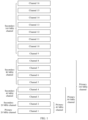
- channel distribution of a 320 MHz bandwidth may be shown in FIG. 1 .
- a 320 MHz channel may be divided into sixteen 20 MHz channels.
- the sixteen 20 MHz channels may be sequentially numbered from a high frequency to a low frequency, or may be sequentially numbered from a low frequency to a high frequency.
- a channel 1 may be used as a primary 20 MHz channel, and a channel 2 may be used as a secondary 20 MHz channel.
- the channel 1 and the channel 2 may be aggregated as a primary 40 MHz channel.
- a channel 3 and a channel 4 may be aggregated as a secondary 40 MHz channel.
- the channel 1 to the channel 4 may be aggregated as a primary 80 MHz channel.
- a channel 5 to a channel 8 may be aggregated as a secondary 80 MHz channel.
- the channel 1 to the channel 8 may be aggregated as a primary 160 MHz channel.
- a channel 9 to a channel 16 may be aggregated as a secondary 160 MHz channel.
- the primary 20 MHz channel is not necessarily a 20 MHz channel located at the beginning.
- the channel 3 may be used as the primary 20 MHz channel
- the channel 4 may be used as the secondary 20 MHz channel
- the channel 3 and the channel 4 may be aggregated as the primary 40 MHz channel
- the channel 1 and the channel 2 may be aggregated as the secondary 40 MHz channel
- the channel 1 to the channel 4 may be aggregated as the primary 80 MHz channel
- the channel 5 to the channel 8 may be aggregated as the secondary 80 MHz channel
- the channel 1 to the channel 8 may be aggregated as the primary 160 MHz channel
- the channel 9 to the channel 16 may be aggregated as the secondary 160 MHz channel.
- the secondary channel may alternatively have another name, for example, a slave channel or an auxiliary channel. This embodiment of this application is not limited thereto.
- control frames are sent in a non-HT duplicated manner on a channel with a bandwidth greater than 20 MHz.
- the control frame uses a non-HT format (in other words, the control frame uses a format that complies with the 802.11a standard), and the control frame is copied to 20 MHz channels in the channels for sending.
- a frame sent in the non-HT duplicated manner is referred to as a non-HT duplicated frame or a frame in a non-HT duplicated format below.
- a transmit end and a receive end are located in different radio channel environments. Therefore, it is very conducive for data communication if a bandwidth available to both the transmit end and the receive end can be negotiated based on channel availability of the transmit end and the receive end before data communication.
- the non-HT duplicated frame or a non-HT frame includes a service field.
- the service field may be divided into two parts. The first seven bits of the service field are used to carry the first seven bits of a scrambling sequence, and the last nine bits of the service field are reserved service bits.
- a B5 bit and a B6 bit in the first seven bits of the scrambling sequence used by the non-HT duplicated frame or the non-HT frame are set as a CH_BANDWIDTH_IN_NON_HT field, where the CH_BANDWIDTH_IN_NON_HT field indicates a bandwidth mode.
- the first seven bits of the scrambling sequence are sequentially numbered a B0 bit to the B6 bit from a low bit to a high bit. Therefore, the B5 bit is the sixth bit in the first seven bits of the scrambling sequence, and the B6 bit is the seventh bit in the first seven bits of the scrambling sequence.
- the bandwidth mode may also be referred to as the channel bandwidth.
- a bandwidth mode indicated by a CH_BANDWIDTH_IN_NON_HT field in a current frame is a channel bandwidth used for transmitting the frame.
- the transmit end uses a unicast (unicast)/multicast (multicast) bit in a transmitter address (transmitter address, TA) field in the non-HT duplicated frame or the non-HT frame to indicate whether the B5 bit and the B6 bit in the first seven bits of the scrambling sequence are used as the CH_BANDWIDTH_IN_NON_HT field.
- TA transmitter address
- the unicast/multicast bit is set to 1, it indicates that the B5 bit and the B6 bit in the first seven bits of the scrambling sequence are used as the CH_BANDWIDTH_IN_NON_HT field.
- the unicast/multicast bit is set to 0, it indicates that the B5 bit and the B6 bit in the first seven bits of the scrambling sequence are not used as the CH_BANDWIDTH_IN_NON_HT field.
- bandwidth modes that may be used between the transmit end and the receive end may exceed the four bandwidth modes shown in Table 2.
- the 802.11be standard supports a maximum transmission bandwidth of 320 MHz
- other bandwidth modes such as 320 MHz may be used between the transmit end and the receive end that use the 802.11be standard.
- the CH_BANDWIDTH_IN_NON_HT field supports only the four bandwidth modes shown in Table 2. Therefore, in a scenario in which other bandwidth modes other than 20 MHz, 40 MHz, 80 MHz, and 80+80 MHz or 160 MHz are introduced, how the non-HT duplicated frame or the non-HT frame indicates a bandwidth mode is a technical problem that needs to be urgently resolved.
- embodiments of this application provide a bandwidth mode indication method and apparatus.
- the technical solutions provided in this application may be applied to various communication systems, for example, a system using the IEEE 802.11 standard.
- the IEEE 802.11 standard includes but is not limited to the 802.11be standard or the next-generation 802.11 standard.
- Scenarios to which the technical solutions of this application are applicable include communication between an access point (access point, AP) and a station (station, STA), communication between APs, communication between STAs, and the like.
- the STAs in this application may be various user terminals, user apparatuses, access apparatuses, subscriber stations, subscriber units, mobile stations, user agents, user devices, or other devices that have a wireless communication function.
- the user terminals may include various handheld devices, vehicle-mounted devices, wearable devices, computing devices that have the wireless communication function or another processing device connected to a wireless modem; and include various forms of user equipment (user equipment, UE), mobile stations (mobile station, MS), terminals (terminal), terminal equipment (terminal equipment), portable communication devices, handheld devices, portable computing devices, entertainment devices, game devices or systems, global positioning system devices, or any other suitable device configured to perform network communication via wireless media.
- the devices mentioned above are collectively referred to as stations or STAs.
- An access point AP in this application is an apparatus that is deployed in a wireless communication network and that provides a wireless communication function for a STA associated with the access point.
- the access point AP may be used as a hub of a communication system, and may be a communication device such as a base station, a router, a gateway, a repeater, a communication server, a switch, or a bridge.
- the base station may include a macro base station, a micro base station, a relay station, and the like in various forms.
- the devices mentioned above are collectively referred to as access points APs.
- the first frame is a non-HT duplicated frame or a non-HT frame, for example, an RTS frame or a CTS frame.
- the first frame includes a service field.
- the service field carried in the first frame occupies 16 bits. In other words, compared with a non-HT duplicated frame or a non-HT frame defined in the 802.11n standard, no bit is added to or removed from the first frame provided in this application, so that the first frame has backward compatibility.
- the service field of the first frame includes a first field, and the first field indicates whether a bandwidth mode indication field carried in the first frame is allowed to indicate a target bandwidth mode.
- the target bandwidth mode includes one or more of bandwidth modes other than 20 MHz, 40 MHz, 80 MHz, and 80+80 MHz or 160 MHz.
- the target bandwidth mode may include 320 MHz (or 160+160 MHz), 240 MHz, or the like. This is not limited herein.
- the first field occupies at least one bit in B7 to B15 bits in the service field.
- the first field occupies the B7 bit, a B11 bit, or the B15 bit in the service field.
- that the first field indicates whether a bandwidth mode indication field carried in the first frame is allowed to indicate a target bandwidth mode includes: When the first field is set to a first preset value, the first field indicates that the bandwidth mode indication field carried in the first frame is not allowed to indicate the target bandwidth mode; or when the first field is set to a second preset value, the first field indicates that the bandwidth mode indication field carried in the first frame is allowed to indicate the target bandwidth mode.
- the first preset value when the first field is implemented by using one bit, the first preset value may be 0, and the second preset value may be 1; or the first preset value may be 1, and the second preset value may be 0.
- that the first field indicates whether a bandwidth mode indication field carried in the first frame is allowed to indicate a target bandwidth mode includes: When the first field is set to the first preset value, the first field indicates that the bandwidth mode indication field carried in the first frame is not allowed to indicate the target bandwidth mode; or when the first field is set to another value other than the first preset value, the first field indicates that the bandwidth mode indication field carried in the first frame is allowed to indicate the target bandwidth mode. There are one or more other values.
- the first field when the first field occupies the plurality of bits, the first field may have another function.
- the first field may further indicates a total bandwidth.
- Design 1 The first field occupies at least one bit, and the first frame indicates the bandwidth mode in the following manner (1-1) or (1-2).
- (1-1) When the first field is set to the first preset value, the first frame does not carry the bandwidth mode indication field, or the bandwidth mode indication field carried in the first frame indicates a bandwidth mode in a first bandwidth mode set.
- the bandwidth mode indication field carried in the first frame indicates a bandwidth mode in a second bandwidth mode set.
- the second bandwidth mode set includes the target bandwidth mode.
- the second bandwidth mode set may include the four bandwidth modes: 20 MHz, 40 MHz, 80 MHz, and 160 MHz (or 80+80 MHz).
- the first bandwidth mode set is a proper subset of the second bandwidth mode set.
- the second bandwidth mode set includes at least five bandwidth modes.
- the second bandwidth mode set does not include the four bandwidth modes: 20 MHz, 40 MHz, 80 MHz, and 160 MHz (or 80+80 MHz).
- the intersection set between the second bandwidth mode set and the first bandwidth mode set is empty.
- a quantity of bandwidth modes included in the second bandwidth mode set is not limited in this embodiment of this application.
- the second bandwidth mode set may include 8 or 63 bandwidth modes.
- Design 2 The first field occupies at least one bit, and the first frame further includes the unicast/multicast bit.
- the first frame indicates the bandwidth mode in the following manners (2-1), (2-2), or (2-3).
- the bandwidth mode indication field carried in the first frame indicates the bandwidth mode in the second bandwidth mode set.
- Design 3 The first field occupies at least one bit, and the first frame further includes the unicast/multicast bit.
- the first frame indicates the bandwidth mode in the following manners (3-1), (3-2), (3-3) or (3-4).
- the bandwidth mode indication field carried in the first frame indicates a bandwidth mode in a third bandwidth mode set.
- the bandwidth mode indication field carried in the first frame indicates a bandwidth mode in a fourth bandwidth mode set.
- At least one of the third bandwidth mode set and the fourth bandwidth mode set includes the target bandwidth mode.
- the bandwidth mode included in the third bandwidth mode set is different from the bandwidth mode included in the fourth bandwidth mode set.
- the third bandwidth mode set may include one or more of the four bandwidth modes: 20 MHz, 40 MHz, 80 MHz, and 160 MHz (or 80+80 MHz), and/or the fourth bandwidth mode set may include one or more of the four bandwidth modes: 20 MHz, 40 MHz, 80 MHz, and 160 MHz (or 80+80 MHz).
- the third bandwidth mode set does not include the four bandwidth modes: 20 MHz, 40 MHz, 80 MHz, and 160 MHz (or 80+80 MHz), and the fourth bandwidth mode set does not include the four bandwidth modes: 20 MHz, 40 MHz, 80 MHz, and 160 MHz (or 80+80 MHz).
- the bandwidth mode indication field carried in the first frame may use any one of the following implementations 1-1 to 1-4.
- Implementation 1-1 The bandwidth mode indication field is implemented by using one or two bits in the first seven bits of the scrambling sequence.
- the bandwidth mode indication field may be implemented by using the B5 bit and the B6 bit in the first seven bits of the scrambling sequence.
- Implementation 1-2 The bandwidth mode indication field is implemented by using at least three bits in the first seven bits of the scrambling sequence.
- the bandwidth mode indication field may be implemented by using a B3 bit, the B5 bit, and the B6 bit in the first seven bits of the scrambling sequence.
- Implementations 1-3 The bandwidth mode indication field is implemented by using one or more bits in the last nine bits of the service field.
- the bandwidth mode indication field occupies six bits B9 to B14 of the service field.
- the bandwidth mode indication field is implemented by using at least one bit in the first seven bits of the scrambling sequence and at least one bit in the last nine bits of the service field.
- the bandwidth mode indication field occupies the two bits B5 to B6 in the scrambling sequence and four bits B11 to B14 in the service field.
- the bandwidth mode indication field occupies the three bits B3, B5, and B6 in the scrambling sequence and the three bits B12 to B14 in the service field.
- the second bandwidth mode set, the third bandwidth mode set, or the fourth bandwidth mode set may include a preamble puncturing bandwidth mode and/or a non-preamble puncturing bandwidth mode.
- the non-preamble puncturing bandwidth mode may also be referred to as a preamble non-puncturing bandwidth mode.
- the preamble puncturing bandwidth mode and the non-preamble puncturing bandwidth mode that are defined by the 802.11be based on non-orthogonal frequency division multiple access (non-orthogonal frequency division multiple access, non-OFDMA).
- Table 3 shows 63 bandwidth modes. In Table 3, one "1” or “X” corresponds to one 20 MHz channel, “1” indicates that the corresponding 20 MHz channel is idle, and “X” indicates that the corresponding 20 MHz channel is busy or not available (no available).
- a total bandwidth corresponding to the bandwidth mode is a bandwidth when preamble puncturing is not performed.
- the total bandwidth may be 20 MHz, 40 MHz, 80 MHz, 160 MHz (or 80+80 MHz), or 320 MHz (or 160+160 MHz).
- Design 4 The first field occupies one bit, and the first frame indicates the bandwidth mode in the following manner (4-1) or (4-2).
- the fourth field may occupy at least one bit, and the fifth field occupies at least one bit.
- the fourth field and the fifth field are located in the service field.
- the fourth field may use any one of the following implementations 2-1 to 2-3.
- the fourth field occupies one bit.
- the fourth field indicates the total bandwidth, and includes the following case 1-1 and/or case 1-2.
- Case 1-1 When a value of the fourth field is an eleventh preset value, it indicates that the total bandwidth is less than or equal to 160 MHz.
- Case 1-2 When the value of the fourth field is a twelfth preset value, it indicates that the total bandwidth is greater than 160 MHz, or the total bandwidth is equal to 320 MHz or 160+160 MHz.
- the fourth field occupies two bits.
- the fourth field indicates the total bandwidth, and includes one or more of the following cases 2-1 to 2-3.
- Case 2-2 When the value of the fourth field is the twelfth preset value, it indicates that the total bandwidth is equal to 160 MHz or 80+80 MHz.
- Case 2-3 When the value of the fourth field is a thirteenth preset value, it indicates that the total bandwidth is equal to 320 MHz or 160+160 MHz.
- the eleventh preset value, the twelfth preset value, and the thirteenth preset value are 0, 1, and 2.
- the fourth field occupies three bits.
- the fourth field indicates the total bandwidth, and includes one or more of the following cases 3-1 to 3-5.
- Case 3-1 When the value of the fourth field is the eleventh preset value, it indicates that the total bandwidth is equal to 20 MHz.
- Case 3-4 When the value of the fourth field is a fourteenth preset value, it indicates that the total bandwidth is equal to 160 MHz or 80+80 MHz.
- Case 3-5 When the value of the fourth field is a fifteenth preset value, it indicates that the total bandwidth is equal to 320 MHz or 160+160 MHz.
- the eleventh preset value to the fifteenth preset value are sequentially 0, 1, 2, 3, and 4.
- the fifth field may use any one of the following implementations 3-1 to 3-4.
- the fifth field occupies eight bits.
- the fifth field indicates the preamble puncturing information corresponding to the total bandwidth, and includes the following case 4-1 or case 4-2.
- each bit in the fifth field corresponds to one 20 MHz channel.
- One bit indicates whether the 20 MHz channel corresponding to the bit is idle.
- channels corresponding to bits in the fifth field are sequentially set in an order from a low frequency to a high frequency.
- a least significant bit corresponds to a low-frequency channel
- a most significant bit corresponds to a high-frequency channel.
- the channels corresponding to the bits in the fifth field are sequentially set in an order from a high frequency to a low frequency.
- a least significant bit corresponds to a high-frequency channel
- a most significant bit corresponds to a low-frequency channel.
- That one bit indicates whether a channel corresponding to the bit is idle may be as follows: When the bit is set to a seventh preset value, it indicates that the channel corresponding to the bit is available; or when the bit is set to an eighth preset value, it indicates that the channel corresponding to the bit is not available or busy.
- the seventh preset value is 0, and the eighth preset value is 1.
- the seventh preset value is 1, and the eighth preset value is 0. This is uniformly described herein, and details are not described below again.
- a channel is not available or busy may be replaced with “a channel is punctured”
- a channel is idle may be replaced with “a channel is not punctured”.
- each bit in the fifth field corresponds to one 40 MHz channel.
- a first bit indicates whether a secondary 20 MHz channel of a primary 40 MHz channel is idle, and the first bit corresponds to the primary 40 MHz channel.
- a second bit indicates whether a 40 MHz channel corresponding to the second bit is idle. The second bit is any one of bits other than the first bit in the fifth field.
- the fifth field occupies eight bits.
- the fifth field indicates the preamble puncturing information corresponding to the total bandwidth, and includes the following case 5-1 or case 5-2.
- each bit in the fifth field corresponds to one 20 MHz channel.
- One bit indicates whether the 20 MHz channel corresponding to the bit is idle.
- the fifth field includes four first bits, two second bits, and two third bits.
- Each of the four first bits corresponds to one 20 MHz channel of a primary 80 MHz channel
- each of the two second bits corresponds to one 40 MHz channel of a secondary 80 MHz channel
- each of the two third bits corresponds to one 80 MHz channel of a secondary 160 MHz channel.
- the first bit indicates whether the 20 MHz channel corresponding to the first bit is idle.
- the second bit indicates whether the 40 MHz channel corresponding to the second bit is idle.
- the third bit indicates whether the 80 MHz channel corresponding to the third bit is idle.
- the fifth field occupies 10 bits.
- the fifth field indicates the preamble puncturing information corresponding to the total bandwidth, and includes the following case 6-1 or case 6-2.
- the fifth field includes four first bits, two second bits, and four third bits.
- Each of the four first bits corresponds to one 20 MHz channel of the primary 80 MHz channel.
- Each of the two second bits corresponds to one 40 MHz channel of the secondary 80 MHz channel.
- Each of the four third bits corresponds to one 40 MHz channel of the secondary 160 MHz channel.
- the first bit indicates whether the 20 MHz channel corresponding to the first bit is idle.
- the second bit indicates whether the 40 MHz channel corresponding to the second bit is idle.
- the third bit indicates whether the 40 MHz channel corresponding to the third bit is idle.
- the fifth field occupies 10 bits.
- the fifth field indicates the preamble puncturing information corresponding to the total bandwidth, and includes the following case 7-1 or case 7-2.
- Case 7-1 When the total bandwidth indicated by the fourth field is less than or equal to 160 MHz, each of the eight bits in the fifth field corresponds to one 20 MHz channel. One bit indicates whether the 20 MHz channel corresponding to the bit is idle.
- the fifth field includes eight first bits and two second bits.
- Each of the eight first bits corresponds to one 20 MHz channel of the primary 160 MHz channel.
- Each of the two second bits corresponds to one 80 MHz channel of the secondary 160 MHz channel.
- the first bit indicates whether the 20 MHz channel corresponding to the first bit is idle.
- the second bit indicates whether the 160 MHz channel corresponding to the second bit is idle.
- Design 5 The first field occupies two bits, and the first frame indicates the bandwidth mode in the following manners (5-1), (5-2), or (5-3).
- the first field When the first field is set to the second preset value, the first field indicates that the total bandwidth is less than or equal to 160 MHz, and the bandwidth mode indication field indicates whether each channel is idle when the total bandwidth is less than or equal to 160 MHz.
- the first field When the first field is set to a third preset value, the first field indicates that the total bandwidth is greater than 160 MHz (or the total bandwidth is equal to 320 MHz), and the bandwidth mode indication field indicates whether each channel is idle when the total bandwidth is greater than 160 MHz.
- Design 6 The first field occupies two bits, and the first frame indicates the bandwidth mode in the following manners (6-1), (6-2), (6-3), or (6-4).
- the first field When the first field is set to the second preset value, the first field indicates that the total bandwidth is equal to 80 MHz, and the bandwidth mode indication field indicates whether each channel is idle when the total bandwidth is equal to 80 MHz.
- Design 7 The first field occupies three bits, and the first frame indicates the bandwidth mode in the following manners (7-1), (7-2), (7-3), (7-4), or (7-5).
- the first field When the first field is set to the second preset value, the first field indicates that the total bandwidth is equal to 20 MHz, and the bandwidth mode indication field indicates whether each channel is idle when the total bandwidth is equal to 20 MHz.
- the first field When the first field is set to the third preset value, the first field indicates that the total bandwidth is equal to 40 MHz, and the bandwidth mode indication field indicates whether each channel is idle when the total bandwidth is equal to 40 MHz.
- the first field When the first field is set to the fourth preset value, the first field indicates that the total bandwidth is equal to 80 MHz, and the bandwidth mode indication field indicates whether each channel is idle when the total bandwidth is equal to 80 MHz.
- the first field When the first field is set to a fifth preset value, the first field indicates that the total bandwidth is equal to 160 MHz, and the bandwidth mode indication field indicates whether each channel is idle when the total bandwidth is equal to 160 MHz.
- the first field When the first field is set to a sixth preset value, the first field indicates that the total bandwidth is equal to 320 MHz, and the bandwidth mode indication field indicates whether each channel is idle when the total bandwidth is equal to 320 MHz.
- the bandwidth mode indication field includes any one of the following implementation 4-1 or implementation 4-2.
- the bandwidth mode indication field occupies eight bits, and each bit in the bandwidth mode indication field corresponds to one 20 MHz channel. One bit indicates whether the 20 MHz channel corresponding to the bit is idle.
- the bandwidth mode indication field occupies 10 bits, and each of the eight fields in the bandwidth mode indication field corresponds to one 20 MHz channel. One bit indicates whether the 20 MHz channel corresponding to the bit is idle.
- the bandwidth mode indication field includes any one of the following implementations 5-1 to 5-4.
- the bandwidth mode indication field occupies eight bits, and each bit in the bandwidth mode indication field corresponds to one 40 MHz channel.
- the first bit indicates whether the secondary 20 MHz channel of the primary 40 MHz channel is idle, and the first bit corresponds to the primary 40 MHz channel.
- the second bit indicates whether the 40 MHz channel corresponding to the second bit is idle.
- the second bit is any one of bits other than the first bit in the bandwidth mode indication field.
- the bandwidth mode indication field occupies eight bits, the bandwidth mode indication field includes four first bits, two second bits, and two third bits, each of the four first bits corresponds to one 20 MHz channel of the primary 80 MHz channel, each of the two second bits corresponds to one 40 MHz channel of the secondary 80 MHz channel, and each of the two third bits corresponds to one 80 MHz of the secondary 160 MHz channel.
- the first bit indicates whether the 20 MHz channel corresponding to the first bit is idle.
- the second bit indicates whether the 40 MHz channel corresponding to the second bit is idle.
- the third bit indicates whether the 80 MHz channel corresponding to the third bit is idle.
- the bandwidth mode indication field occupies 10 bits, and the bandwidth mode indication field includes four first bits, two second bits, and four third bits.
- Each of the four first bits corresponds to one 20 MHz channel of the primary 80 MHz channel.
- Each of the two second bits corresponds to one 40 MHz channel of the secondary 80 MHz channel.
- Each of the four third bits corresponds to one 40 MHz channel of the secondary 160 MHz channel.
- the first bit indicates whether the 20 MHz channel corresponding to the first bit is idle.
- the second bit indicates whether the 40 MHz channel corresponding to the second bit is idle.
- the third bit indicates whether the 40 MHz channel corresponding to the third bit is idle.
- the bandwidth mode indication field occupies 10 bits, and the bandwidth mode indication field includes eight first bits and two second bits. Each of the eight first bits corresponds to one 20 MHz channel of the primary 160 MHz channel. Each of the two second bits corresponds to one 80 MHz channel of the secondary 160 MHz channel. The first bit indicates whether the 20 MHz channel corresponding to the first bit is idle. The second bit indicates whether the 160 MHz channel corresponding to the second bit is idle.
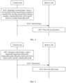
- an embodiment of this application provides a bandwidth mode indication method.
- the method includes the following steps.
- the transmit end supports the 802.11be standard, or supports the next-generation 802.11 standard of the 802.11be standard. It may be understood that the transmit end may be backward compatible with a previous standard protocol, for example, support the 802.11ax standard and the 802.11ax standard before the 802.11ax standard.
- the transmit end may be an AP, or may be a STA.
- the transmit end may determine a value of a related field (for example, the first field) in the first frame based on factors such as a requirement of the transmit end and a protocol supported by a peer device (namely, a receive end in the following).
- the transmit end may set the value of the first field in the first frame to the first preset value or the second preset value.
- the transmit end can only set the value of the first field in the first frame to the first preset value.
- the receive end when the receive end learns, through parsing, that the value of the first field in the first frame is the second preset value, the receive end may determine that the transmit end of the first frame (namely, the transmit end) supports the 802.11be standard or the next-generation 802.11 standard.
- the first frame uses only at least one bit in the service field as the first field, and does not increase or decrease a bit in the service field. In this way, backward compatibility of the first frame is ensured.
- the first field indicates whether the bandwidth mode indication field carried in the first frame is allowed to indicate the target bandwidth mode.
- the bandwidth mode indication field carried in the first frame extends a range of bandwidth modes that can be indicated. Therefore, in a scenario in which other bandwidth modes other than 20 MHz, 40 MHz, 80 MHz, and 80+80 MHz or 160 MHz are introduced, two devices can negotiate, by transmitting the first frame, to use one bandwidth mode from more bandwidth modes.
- the first field is located in the service field of the first frame has the following advantages: (1) Currently, a reserved bit in a MAC frame may be used by a chip vendor as a private indication bit. Therefore, if the reserved bit in the MAC frame is used as the first field, indication of the private bit is affected. However, using the bit in the service field as the first field can avoid affecting private use of the reserved bit in the MAC frame by the chip vendor. (2) Reserved bits in MAC frames of different types of conventional frames do not necessarily have the same location. Therefore, for the different types of transmission frames, implementation solutions of using the reserved bits in the MAC frames as the first field are different.
- the service field is a field introduced to perform a scrambling operation at a physical layer. The service field is located before the MAC frame, and the service field itself is a field at the physical layer, in other words, all types of conventional frames include the service field. In this way, using the bit in the service field as the first field is applicable to all types of conventional frames.
- the second frame is a non-HT duplicated frame or a non-HT frame, for example, an RTS frame or a CTS frame.
- the second frame includes a service field.
- the service field carried in the second frame occupies 16 bits. In other words, compared with the non-HT duplicated frame or the non-HT frame defined in the 802.11n standard, no bit is added to or removed from the second frame provided in this application, so that the second frame has backward compatibility.
- the service field of the second frame includes a second field, the second field indicates whether a bandwidth mode of the second frame is a target bandwidth mode, and the target bandwidth mode includes one or more of bandwidth modes other than 20 MHz, 40 MHz, 80 MHz, and 80+80 MHz or 160 MHz.
- the target bandwidth mode includes a preamble puncturing bandwidth mode and/or a non-preamble puncturing bandwidth mode.
- the second field occupies at least one bit in B7 to B15 bits in the service field.
- the second field occupies the B7 bit, a B11 bit, or the B15 bit in the service field.
- that the second field indicates whether a bandwidth mode of the second frame is a target bandwidth mode includes the following case (8-1) or case (8-2).
- the first frame does not carry the bandwidth mode indication field, or the bandwidth mode indication field carried in the first frame indicates the bandwidth mode in the first bandwidth mode set.
- the bandwidth mode indication field carried in the first frame is implemented by using two bits (for example, the B5 bit and the B6 bit) in the first seven bits of the scrambling sequence.
- Bandwidth modes included in the first bandwidth mode set are 20 MHz, 40 MHz, 80 MHz, and 80+80 MHz or 160 MHz.
- the second frame further includes a unicast/multicast bit
- the case (8-2) may be further classified into the following case (8-2-1) or case (8-2-2).
- the ninth preset value may be 0, and the tenth preset value may be 1; or the tenth preset value may be 1, and the ninth preset value may be 0.
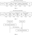
- an embodiment of this application provides a bandwidth mode indication method.
- the method includes the following steps.
- the transmit end supports the 802.11be standard, or supports the next-generation 802.11 standard of the 802.11be standard. It may be understood that the transmit end may be backward compatible with the previous standard protocol, for example, support the 802.11ax standard and the 802.11ax standard before the 802.11ax standard.
- the transmit end may be an AP, or may be a STA.
- the transmit end may determine a value of a related field (for example, the second field) in the second frame based on factors such as the requirement of the transmit end and the protocol supported by the receive end.
- a related field for example, the second field
- S202 The transmit end sends the second frame to the receive end, so that the receive end receives the second frame.
- S203 The receive end parses the second frame.
- the second frame uses only at least one bit in the service field as the second field, and does not increase or decrease a bit in the service field. In this way, backward compatibility of the second frame is ensured.
- the second field indicates whether the bandwidth mode of the second frame is the target bandwidth mode. Therefore, in a scenario in which other bandwidth modes other than 20 MHz, 40 MHz, 80 MHz, and 80+80 MHz or 160 MHz are introduced, two devices can negotiate, by transmitting the second frame, to use one bandwidth mode from more bandwidth modes.
- the first field or the second field may have another name, for example, an EHT bandwidth indication field. This is not limited in this embodiment of this application.
- the second field is located in the service field of the second frame has the following advantages: (1) Currently, a reserved bit in a MAC frame may be used by a chip vendor as a private indication bit. Therefore, if the reserved bit in the MAC frame is used as the second field, indication of the private bit is affected. However, using the bit in the service field as the second field can avoid affecting private use of the reserved bit in the MAC frame by the chip vendor. (2) Reserved bits in MAC frames of different types of conventional frames do not necessarily have the same location. Therefore, for the different types of transmission frames, implementation solutions of using the reserved bits in the MAC frames as the second field are different.
- the service field is a field introduced to perform a scrambling operation at a physical layer. The service field is located before the MAC frame, and the service field itself is a field at the physical layer, in other words, all types of conventional frames include the service field. In this way, using the bit in the service field as the second field is applicable to all types of conventional frames.
- the transmit end sends an RTS frame after backoff is terminated.
- the transmit end may send the RTS frame in a non-HT duplicated manner.
- a CH_BANDWIDTH_IN_NON_HT field indicates a bandwidth mode
- a DYN_BANDWIDTH_IN_NON_HT field indicates a bandwidth negotiation mode.
- the CH_BANDWIDTH_IN_NON_HT field is implemented by using the B5 bit and the B6 bit in the first seven bits of the scrambling sequence.
- the DYN_BANDWIDTH_IN_NON_HT field is implemented by using the B4 bit in the first seven bits of the scrambling sequence.
- the DYN_BANDWIDTH_IN_NON_HT field is set to 0, it indicates static bandwidth negotiation.
- the DYN_BANDWIDTH_IN_NON_HT field is set to 1, it indicates dynamic bandwidth negotiation.
- the receive end After the receive end receives the RTS frame, when the DYN_BANDWIDTH_IN_NON_HT field is set to 0, if an NAV indicates idle, and a bandwidth CCA detection result indicated by the RTS frame is idle, the receive end replies with a non-HT duplicated CTS frame by using a bandwidth indicated by the RTS frame.
- the receiving station After the receive end receives the RTS frame, when the DYN_BANDWIDTH_IN_NON_HT field is set to 1, if the NAV indicates idle, and the bandwidth CCA detection result indicated by the RTS frame is that all or some channels (including the primary 20 MHz channel) are idle, the receiving station replies with the non-HT duplicated CTS frame by using a bandwidth the same as or smaller than that of the RTS frame.
- the Applicant finds that when the bandwidth mode indicated by the CH_BANDWIDTH_IN_NON_HT field in the RTS frame is 20 MHz, regardless of whether the DYN_BANDWIDTH_IN_NON_HT field is set to 0 or 1, the receive end uses the same processing manner: When the primary 20 MHz channel is busy, the receive end does not reply with the CTS frame; and when the primary 20 MHz channel is idle, the receive end replies with the CTS frame, and the CH_BANDWIDTH_IN_NON_HT field carried in the CTS frame indicates 20 MHz.
- an embodiment of this application provides a third frame.
- the third frame is a non-HT duplicated frame or a non-HT frame, for example, an RTS frame or a CTS frame.
- the third frame includes a bandwidth negotiation field and a bandwidth mode indication field.
- the bandwidth negotiation field and the bandwidth mode indication field in the third frame jointly indicate a bandwidth mode of the third frame.
- the bandwidth mode of the third frame is 20 MHz, 40 MHz, 80 MHz, 80+80 MHz or 160 MHz, or a first bandwidth mode.
- the first bandwidth mode is one of bandwidth modes other than 20 MHz, 40 MHz, 80 MHz, and 80+80 MHz or 160 MHz, for example, 320 MHz.
- the bandwidth negotiation field occupies the B4 bit in the first seven bits of the scrambling sequence.
- the bandwidth mode indication field occupies the B5 bit and the B6 bit in the first seven bits of the scrambling sequence.
- bandwidth negotiation field and the bandwidth mode indication field jointly indicate a bandwidth mode used by the third frame includes the following cases:
- bandwidth negotiation field when the bandwidth negotiation field is set to 0, it indicates that static bandwidth negotiation is used. When the bandwidth negotiation field is set to 1, it indicates that dynamic bandwidth negotiation is used.
- an embodiment of this application provides a bandwidth mode indication method.
- the method includes the following steps.
- the transmit end supports the 802.11be standard, or supports the next-generation 802.11 standard of the 802.11be standard. It may be understood that the transmit end may be backward compatible with the previous standard protocol, for example, support the 802.11ax standard and the 802.11ax standard before the 802.11ax standard.
- the transmit end may be an AP, or may be a STA.
- the third frame provided in this application fully uses a redundant state in the bandwidth negotiation field and the bandwidth mode indication field to indicate a new bandwidth mode (the first bandwidth mode). Therefore, the bandwidth negotiation field and the bandwidth mode indication field in the third frame jointly indicate one of five bandwidth modes. In this way, the third frame is transmitted between two devices, and one of the five bandwidth modes can be used through negotiation.
- no bit is added to or removed from the third frame provided in this application. In this way, backward compatibility of the third frame is ensured.
- the CTS frame used to respond to the MU-RTS frame is a conventional frame, so that the CTS frame does not have sufficient idle bits for use by the bandwidth mode indication field. Therefore, the current CTS frame is not applicable to the scenario in which more bandwidth modes are introduced to the communication system.
- an embodiment of this application provides a fourth frame.
- the fourth frame is used to respond to the MU-RTS frame or the RTS frame.
- a MAC frame of the fourth frame occupies 112+N bits, where N is a positive integer.
- One or more of the N bits indicates a bandwidth mode.
- the bandwidth mode may be a preamble puncturing bandwidth mode or a non-preamble puncturing bandwidth mode.
- the fourth frame may further provide more idle bits to indicate the bandwidth mode, to indicate one bandwidth mode from the at least five bandwidth modes.
- NAVTimeout is the fixed time length, to ensure normal execution of the NAV reset mechanism based on the RTS/CTS or MU-RTS/CTS interaction, transmission duration of the fourth frame should be consistent with transmission duration of the CTS frame.
- the fourth frame also needs six OFDM symbols for transmission.
- the six OFDM symbols can transmit a maximum of 18 bytes of data. Therefore, compared with the CTS frame, a maximum of 10 bits may be added to the fourth frame. In other words, N is less than or equal to 10.
- N may be equal to 8.
- the fourth frame may meet a rule of increasing a length of the MAC frame by an integer byte.
- a location of the third field in the fourth frame is not limited in this embodiment of this application.
- the third field may also be located between the transmitter address field and the duration field.
- the 16 bits may include eight bits in the third field and eight bits in the service field.
- the eight bits in the service field may be any eight of the last nine bits (namely, the B7 bit to the B15 bit) of the service field.
- the M bits in the service field include a B0 bit to a B6 bit in the service field, it needs to be ensured that not all of the B0 bit to the B6 bit are set to 0, to avoid that a scrambling process cannot work normally.
- this application provides a bandwidth mode indication method. As shown in FIG. 8 , the method includes the following steps.
- the transmit end when the transmit end determines that the receive end supports the 802.11be standard or the next-generation 802.11 standard, the transmit end generates the fourth frame.
- S402 The transmit end sends the fourth frame, so that the receive end receives the fourth frame.
- the fourth frame has more idle bits that indicate bandwidth modes.
- the transmit end sends the third frame to the receive end, to use one bandwidth mode from more bandwidth modes.
- the communication apparatus includes corresponding hardware structures and/or software modules for performing the functions.
- modules, algorithms and steps may be implemented by hardware or a combination of hardware and computer software in this application. Whether a function is performed by hardware or hardware driven by computer software depends on particular applications and design constraint conditions of the technical solutions.
- a person skilled in the art may use different methods to implement the described functions for each particular application, but it should not be considered that the implementation goes beyond the scope of this application.
- the apparatus may be divided into functional modules based on the foregoing method examples.
- each functional module may be obtained through division based on a corresponding function, or two or more functions may be integrated into one functional module.
- the integrated module may be implemented in a form of hardware, or may be implemented in a form of a software functional module.
- module division is an example, and is merely a logical function division. In actual implementation, another division manner may be used.
- An example in which each function module is obtained through division based on each corresponding function is used below for description.
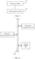
- FIG. 9 shows a communication apparatus according to an embodiment of this application.
- the communication apparatus includes a processing module 101 and a communication module 102.
- the processing module 101 is configured to perform step S101 in FIG. 3
- the communication module is configured to perform step S102 in FIG. 3 .
- the processing module 101 is configured to perform step S201 in FIG. 4
- the communication module 102 is configured to perform step S202 in FIG. 4 .
- the processing module 101 is configured to perform step S301 in FIG. 5
- the communication module 102 is configured to perform step S302 in FIG. 5 .
- the processing module 101 is configured to perform step S401 in FIG. 8
- the communication module 102 is configured to perform step S402 in FIG. 8 .
- the processing module 101 is configured to perform step S103 in FIG. 3
- the communication module 102 is configured to perform step S102 in FIG. 3 .
- the processing module 101 is configured to perform step S203 in FIG. 4
- the communication module 102 is configured to perform step S202 in FIG. 4 .
- the processing module 101 is configured to perform step S303 in FIG. 5
- the communication module 102 is configured to perform step S302 in FIG. 5 .
- the processing module 101 is configured to perform step S403 in FIG. 8
- the communication module 102 is configured to perform step S402 in FIG. 8 .
- FIG. 10 is a diagram of a structure of a possible product form of a communication apparatus according to an embodiment of this application.
- the communication apparatus in this embodiment of this application may be a communication device, and the communication device includes a processor 201 and a transceiver 202.
- the communication device further includes a storage medium 203.
- the processor 201 is configured to perform step S101 in FIG. 3
- the transceiver 202 is configured to perform step S102 in FIG. 3 .
- the processor 201 is configured to perform step S201 in FIG. 4
- the transceiver 202 is configured to perform step S202 in FIG. 4 .
- the processor 201 is configured to perform step S301 in FIG. 5
- the transceiver 202 is configured to perform step S302 in FIG. 5 .
- the processor 201 is configured to perform step S401 in FIG. 8
- the transceiver 202 is configured to perform step S402 in FIG. 8 .
- the processor 201 is configured to perform step S103 in FIG. 3
- the transceiver 202 is configured to perform step S102 in FIG. 3 .
- the processor 201 is configured to perform step S203 in FIG. 4
- the transceiver 202 is configured to perform step S202 in FIG. 4 .
- the processor 201 is configured to perform step S303 in FIG. 5
- the transceiver 202 is configured to perform step S302 in FIG. 5 .
- the processor 201 is configured to perform step S403 in FIG. 8
- the transceiver 202 is configured to perform step S402 in FIG. 8 .
- the communication apparatus described in embodiments of this application may alternatively be implemented by using the following circuit or component: one or more field programmable gate arrays (field programmable gate arrays, FPGA), programmable logic devices (programmable logic devices, PLD), controllers, state machines, gate logic, discrete hardware components, any other appropriate circuits, or any combination of circuits that can perform the functions described in this application.
- field programmable gate arrays field programmable gate arrays, FPGA
- programmable logic devices programmable logic devices
- PLD programmable logic devices
- controllers state machines, gate logic, discrete hardware components, any other appropriate circuits, or any combination of circuits that can perform the functions described in this application.
- computer instructions may be stored in a computer-readable storage medium or may be transmitted from a computer-readable storage medium to another computer-readable storage medium.
- the computer instructions may be transmitted from a website, computer, server, or data center to another website, computer, server, or data center in a wired (for example, a coaxial cable, an optical fiber, or a digital subscriber line) or wireless (for example, infrared, radio, or microwave) manner.
- the computer-readable storage medium may be any usable medium accessible by a computer, or a data storage device, such as a server or a data center, integrating one or more usable media.
- the usable medium may be a magnetic medium (for example, a floppy disk, a hard disk, or a magnetic tape), an optical medium, a semiconductor medium (for example, a solid-state drive), or the like.
- each of the units may exist alone physically, or two or more units may be integrated into one unit.
- the integrated unit may be implemented in a form of hardware, or may be implemented in a form of a software functional unit.
Landscapes
- Engineering & Computer Science (AREA)
- Signal Processing (AREA)
- Computer Networks & Wireless Communication (AREA)
- Quality & Reliability (AREA)
- Mobile Radio Communication Systems (AREA)
Claims (13)
- Verfahren zur Anzeige eines Bandbreitenmodus, wobei das Verfahren Folgendes umfasst:Erzeugen eines Frames (S101), wobei der Frame ein Frame mit niedrigem Durchsatz (non-high throughput, non-HT) oder ein duplizierter Frame mit niedrigem Durchsatz (non-HT duplicated) ist, der Frame ein Servicefeld umfasst, das Servicefeld 16 Bits B0-B15 einnimmt, die ersten sieben Bits B0-B6 des Servicefelds eine Verschlüsselungssequenz tragen, und der Frame ferner ein Unicast/Multicast-Bit umfasst;wobei das Unicast/Multicast-Bit anzeigt, ob ein in dem Frame getragenes Bandbreitenmodus-Anzeigefeld einen Bandbreitenmodus anzeigt; undwenn das Unicast/Multicast-Bit auf 1 gesetzt wird und ein B7-Bit des Servicefelds auf einen ersten voreingestellten Wert gesetzt wird, das in dem Frame getragene Bandbreitenmodus-Anzeigefeld einen Bandbreitenmodus in einem ersten Bandbreitenmodussatz anzeigt, wobei der erste Bandbreitenmodussatz 20 MHz, 40 MHz, 80 MHz und 80+80 MHz oder 160 MHz umfasst;wenn das Unicast/Multicast-Bit auf 1 gesetzt wird und das B7-Bit des Servicefelds auf einen zweiten voreingestellten Wert gesetzt wird, das im Frame getragene Bandbreitenmodus-Anzeigefeld einen Bandbreitenmodus in einem zweiten Bandbreitenmodussatz anzeigt, wobei der zweite Bandbreitenmodussatz einen Zielbandbreitenmodus umfasst und der Zielbandbreitenmodus 320 MHz oder 160 + 160 MHz umfasst;wenn das Unicast/Multicast-Bit auf 0 gesetzt wird, das Bandbreitenmodus-Anzeigefeld nicht verwendet wird, um den Bandbreitenmodus anzuzeigen; unddas Verfahren ferner Senden des Frames (S102) umfasst.
- Verfahren zur Anzeige eines Bandbreitenmodus, wobei das Verfahren Folgendes umfasst:Empfangen eines Frames (S102), wobei der Frame ein Frame mit niedrigem Durchsatz oder ein duplizierter Frame mit niedrigem Durchsatz ist, der Frame ein Servicefeld umfasst, das Servicefeld 16 Bits B0-B15 einnimmt, die ersten sieben Bits B0-B6 des Servicefelds eine Verschlüsselungssequenz tragen, und der Frame ferner ein Unicast/Multicast-Bit umfasst;wobei das Unicast/Multicast-Bit anzeigt, ob ein im Frame mitgeführtes Bandbreitenmodus-Anzeigefeld einen Bandbreitenmodus anzeigt;wenn das Unicast/Multicast-Bit auf 1 gesetzt wird und ein B7-Bit des Servicefelds auf einen ersten voreingestellten Wert gesetzt wird, ein im Frame getragene Bandbreitenmodus-Anzeigefeld einen Bandbreitenmodus in einem ersten Bandbreitenmodussatz anzeigt, wobei der erste Bandbreitenmodussatz 20 MHz, 40 MHz, 80 MHz und 80+80 MHz oder 160 MHz umfasst;wenn das Unicast/Multicast-Bit auf 1 gesetzt wird und das B7-Bit des Servicefelds auf einen zweiten voreingestellten Wert gesetzt wird, das im Frame getragene Bandbreitenmodus-Anzeigefeld einen Bandbreitenmodus in einem zweiten Bandbreitenmodussatz anzeigt, wobei der zweite Bandbreitenmodussatz einen Zielbandbreitenmodus umfasst und der Zielbandbreitenmodus 320 MHz oder 160 + 160 MHz umfasst;wenn das Unicast/Multicast-Bit auf 0 gesetzt wird, das Bandbreitenmodus-Anzeigefeld nicht verwendet wird, um den Bandbreitenmodus anzuzeigen; unddas Verfahren ferner Parsen des Frames (S103) umfasst.
- Verfahren gemäß Anspruch 1 oder 2, wobei der erste voreingestellte Wert 0 ist und der zweite voreingestellte Wert 1 ist.
- Verfahren gemäß einem der Ansprüche 1 bis 3, wobei das Bandbreitenmodus-Anzeigefeld ein B5-Bit und ein B6-Bit des Servicefelds umfasst.
- Verfahren gemäß einem der Ansprüche 1 bis 4, wobei das Bandbreitenmodus-Anzeigefeld das Feld CH_BANDWIDTH_IN_NON_HT ist.
- Verfahren gemäß einem der Ansprüche 1 bis 5, wobei der Zielbandbreitenmodus einen Präambelpunktierungsbandbreitenmodus und/oder einen Nicht-Präambelpunktierungsbandbreitenmodus umfasst.
- Kommunikationsvorrichtung, umfassend:einen Prozessor; undein Speichermedium, das zum Speichern von Computeranweisungen konfiguriert ist, die, wenn sie durch den Prozessor ausgeführt werden, die Kommunikationsvorrichtung dazu veranlassen, das Verfahren gemäß einem der Ansprüche 1 und 3 bis 6 durchzuführen.
- Kommunikationsvorrichtung, umfassend:einen Prozessor; undein Speichermedium, das zum Speichern von Computeranweisungen konfiguriert ist, die, wenn sie durch den Prozessor ausgeführt werden, die Kommunikationsvorrichtung dazu veranlassen, das Verfahren gemäß einem der Ansprüche 2 bis 6 durchzuführen.
- Computerlesbares Speichermedium, wobei das computerlesbare Speichermedium Anweisungen speichert; und der Computer bei Ausführung der Anweisungen auf einem Computer in die Lage versetzt wird, das Verfahren gemäß einem der Ansprüche 1 und 3 bis 6 durchzuführen.
- Computerlesbares Speichermedium, wobei das computerlesbare Speichermedium Anweisungen speichert, und wenn die Anweisungen auf einem Computer ausgeführt werden, der Computer in die Lage versetzt wird, das Verfahren gemäß einem der Ansprüche 2 bis 6 durchzuführen.
- Chip, wobei der Chip eine Verarbeitungseinheit und einen Transceiver-Pin umfasst, die Verarbeitungseinheit dazu konfiguriert ist, einen Verarbeitungsvorgang im Verfahren gemäß einem der Ansprüche 1 und 3 bis 8 durchzuführen, und der Transceiver-Pin dazu konfiguriert ist, einen Kommunikationsvorgang im Verfahren gemäß einem der Ansprüche 1 und 3 bis 6 durchzuführen.
- Chip, wobei der Chip eine Verarbeitungseinheit und einen Transceiver-Pin umfasst, die Verarbeitungseinheit dazu konfiguriert ist, einen Verarbeitungsvorgang im Verfahren gemäß einem der Ansprüche 2 bis 6 durchzuführen, und der Transceiver-Pin dazu konfiguriert ist, einen Kommunikationsvorgang im Verfahren gemäß einem der Ansprüche 2 bis 6 durchzuführen.
- Computerprogrammprodukt, wobei, wenn das Computerprogrammprodukt auf einem Computer ausgeführt wird, der Computer in die Lage versetzt wird, das Verfahren gemäß einem der Ansprüche 1 bis 6 durchzuführen.
Applications Claiming Priority (2)
| Application Number | Priority Date | Filing Date | Title |
|---|---|---|---|
| CN202010791002.2A CN114071581A (zh) | 2020-08-07 | 2020-08-07 | 带宽模式指示方法及装置 |
| PCT/CN2021/111491 WO2022028618A1 (zh) | 2020-08-07 | 2021-08-09 | 带宽模式指示方法及装置 |
Publications (4)
| Publication Number | Publication Date |
|---|---|
| EP4192096A1 EP4192096A1 (de) | 2023-06-07 |
| EP4192096A4 EP4192096A4 (de) | 2023-12-27 |
| EP4192096B1 true EP4192096B1 (de) | 2025-06-25 |
| EP4192096C0 EP4192096C0 (de) | 2025-06-25 |
Family
ID=80117090
Family Applications (1)
| Application Number | Title | Priority Date | Filing Date |
|---|---|---|---|
| EP21852429.6A Active EP4192096B1 (de) | 2020-08-07 | 2021-08-09 | Verfahren und vorrichtung zur anzeige eines bandbreitenmodus |
Country Status (10)
| Country | Link |
|---|---|
| US (1) | US20230188309A1 (de) |
| EP (1) | EP4192096B1 (de) |
| JP (2) | JP7688115B2 (de) |
| KR (1) | KR20230048375A (de) |
| CN (3) | CN116347527B (de) |
| AU (2) | AU2021319726B2 (de) |
| CA (1) | CA3188713A1 (de) |
| ES (1) | ES3038873T3 (de) |
| MX (1) | MX2023001577A (de) |
| WO (1) | WO2022028618A1 (de) |
Families Citing this family (1)
| Publication number | Priority date | Publication date | Assignee | Title |
|---|---|---|---|---|
| CN114650564A (zh) * | 2020-12-18 | 2022-06-21 | 华为技术有限公司 | 一种协议数据单元ppdu的传输方法和装置 |
Family Cites Families (22)
| Publication number | Priority date | Publication date | Assignee | Title |
|---|---|---|---|---|
| US8867574B2 (en) * | 2010-06-02 | 2014-10-21 | Qualcomm Incorporated | Format of VHT-SIG-B and service fields in IEEE 802.11AC |
| US8873384B2 (en) * | 2010-11-01 | 2014-10-28 | Cisco Technology, Inc. | Bandwidth indication in RTS/CTS frames |
| KR101703107B1 (ko) * | 2011-05-12 | 2017-02-07 | 한국전자통신연구원 | 무선랜 시스템에서 데이터 프레임을 전송하는 방법 및 이를 지원하는 장치 |
| CN103348742B (zh) * | 2012-02-03 | 2016-08-17 | Lg电子株式会社 | 由无线局域网系统中在省电模式操作的站进行的发送和接收帧的方法以及用于该方法的设备 |
| US9668169B2 (en) * | 2014-01-09 | 2017-05-30 | Qualcomm Incorporated | Bandwidth indication in a frame |
| US20150296454A1 (en) * | 2014-04-15 | 2015-10-15 | Newracom, Inc. | Method for low-power communications in wireless local area network and apparatus for the same |
| US9609090B2 (en) * | 2014-04-28 | 2017-03-28 | Newracom, Inc. | Signaling method |
| US20160119453A1 (en) * | 2014-10-22 | 2016-04-28 | Qualcomm Incorporated | Methods and apparatus for guard interval indication in wireless communication networks |
| KR20160084301A (ko) * | 2015-01-05 | 2016-07-13 | 뉴라컴 인코포레이티드 | 동적 대역폭 할당 방법 |
| US10425917B2 (en) | 2015-04-21 | 2019-09-24 | Qualcomm Incorporated | Legacy compatible signaling for channel bonding |
| CN104883711B (zh) * | 2015-04-28 | 2018-05-04 | 江苏中兴微通信息科技有限公司 | 一种增强型动态带宽机制及其收发装置 |
| WO2017008306A1 (zh) * | 2015-07-16 | 2017-01-19 | 华为技术有限公司 | 携带指示信息的数据传输方法、装置及系统 |
| WO2019032216A1 (en) * | 2017-08-11 | 2019-02-14 | Intel Corporation | DETERMINING A NUMBER OF SPACE FLUXES AND A BANDWIDTH |
| US20190116513A1 (en) * | 2017-10-16 | 2019-04-18 | Qualcomm Incorporated | Extremely high throughput (eht) signal detection |
| US10880066B2 (en) * | 2018-01-30 | 2020-12-29 | Qualcomm Incorporated | Multiplexing clients in wireless local area network transmissions |
| CN110621043B (zh) * | 2018-06-20 | 2022-12-27 | 华为技术有限公司 | 一种带宽模式指示方法、信道指示方法及装置 |
| US11160084B2 (en) * | 2018-07-05 | 2021-10-26 | Qualcomm Incorporated | Supporting 320 MHz operating BW |
| US11490261B2 (en) * | 2018-07-10 | 2022-11-01 | Lg Electronics Inc. | Method and device for transmitting data in wireless LAN system |
| CN116405161B (zh) * | 2018-07-17 | 2024-01-16 | 华为技术有限公司 | 一种通信方法及装置 |
| CN110769467B (zh) * | 2018-07-28 | 2023-04-11 | 华为技术有限公司 | 一种带宽信息的指示方法和通信设备 |
| CN111162885B (zh) * | 2018-11-07 | 2024-05-03 | 华为技术有限公司 | 一种多频段指示方法和通信设备 |
| CN113261364B (zh) * | 2019-01-10 | 2025-02-18 | 松下电器(美国)知识产权公司 | 用于持久分配的通信装置和通信方法 |
-
2020
- 2020-08-07 CN CN202310378888.1A patent/CN116347527B/zh active Active
- 2020-08-07 CN CN202410735354.4A patent/CN118540747B/zh active Active
- 2020-08-07 CN CN202010791002.2A patent/CN114071581A/zh active Pending
-
2021
- 2021-08-09 WO PCT/CN2021/111491 patent/WO2022028618A1/zh not_active Ceased
- 2021-08-09 AU AU2021319726A patent/AU2021319726B2/en active Active
- 2021-08-09 EP EP21852429.6A patent/EP4192096B1/de active Active
- 2021-08-09 CA CA3188713A patent/CA3188713A1/en active Pending
- 2021-08-09 JP JP2023508540A patent/JP7688115B2/ja active Active
- 2021-08-09 ES ES21852429T patent/ES3038873T3/es active Active
- 2021-08-09 KR KR1020237007828A patent/KR20230048375A/ko active Pending
- 2021-08-09 MX MX2023001577A patent/MX2023001577A/es unknown
-
2023
- 2023-02-07 US US18/165,837 patent/US20230188309A1/en active Pending
-
2024
- 2024-11-13 AU AU2024264587A patent/AU2024264587A1/en active Pending
-
2025
- 2025-05-22 JP JP2025085267A patent/JP2025124724A/ja active Pending
Also Published As
| Publication number | Publication date |
|---|---|
| CN116347527B (zh) | 2023-11-28 |
| US20230188309A1 (en) | 2023-06-15 |
| EP4192096A4 (de) | 2023-12-27 |
| EP4192096A1 (de) | 2023-06-07 |
| AU2021319726A1 (en) | 2023-03-16 |
| JP7688115B2 (ja) | 2025-06-03 |
| AU2024264587A1 (en) | 2024-11-28 |
| AU2021319726B2 (en) | 2024-08-22 |
| JP2023536529A (ja) | 2023-08-25 |
| ES3038873T3 (en) | 2025-10-15 |
| JP2025124724A (ja) | 2025-08-26 |
| CN116347527A (zh) | 2023-06-27 |
| MX2023001577A (es) | 2023-05-09 |
| CN114071581A (zh) | 2022-02-18 |
| KR20230048375A (ko) | 2023-04-11 |
| CA3188713A1 (en) | 2022-02-10 |
| CN118540747A (zh) | 2024-08-23 |
| WO2022028618A1 (zh) | 2022-02-10 |
| EP4192096C0 (de) | 2025-06-25 |
| CN118540747B (zh) | 2025-11-07 |
Similar Documents
| Publication | Publication Date | Title |
|---|---|---|
| EP3982687B1 (de) | Verfahren und vorrichtung für kommunikationsschutz | |
| US12028842B2 (en) | Data transmission method and communications apparatus | |
| US20220263611A1 (en) | Data transmission method and apparatus | |
| US11177924B2 (en) | Method and apparatus for indicating channel in wireless local area network | |
| US10798716B2 (en) | Network device, terminal device, and resource allocation method | |
| EP4080965B1 (de) | Verfahren und gerät zum anzeigen der zusammenführung mehrerer ressourceneinheiten | |
| CN114585071A (zh) | 使用多基本服务标识符集的无线通信方法和无线通信终端 | |
| JP2023528373A (ja) | 通信方法及び装置 | |
| KR102409918B1 (ko) | 수신된 프레임의 베이직 서비스 세트 식별 정보 판단을 이용한 무선 통신 방법 및 무선 통신 단말 | |
| EP4199567A1 (de) | Kommunikationsverfahren und -vorrichtung | |
| US20240214163A1 (en) | Physical Layer Protocol Data Unit Transmission Method and Apparatus | |
| EP4192096B1 (de) | Verfahren und vorrichtung zur anzeige eines bandbreitenmodus | |
| EP4247051A1 (de) | Bandbreitenanzeigeverfahren, vorrichtung, chip und kommunikationssystem | |
| EP4250811A1 (de) | Kommunikationsverfahren, -vorrichtung und -system | |
| WO2025139796A1 (zh) | 一种通信方法及装置 | |
| BR122024010615A2 (pt) | Método e aparelho de comunicação |
Legal Events
| Date | Code | Title | Description |
|---|---|---|---|
| STAA | Information on the status of an ep patent application or granted ep patent |
Free format text: STATUS: THE INTERNATIONAL PUBLICATION HAS BEEN MADE |
|
| PUAI | Public reference made under article 153(3) epc to a published international application that has entered the european phase |
Free format text: ORIGINAL CODE: 0009012 |
|
| STAA | Information on the status of an ep patent application or granted ep patent |
Free format text: STATUS: REQUEST FOR EXAMINATION WAS MADE |
|
| 17P | Request for examination filed |
Effective date: 20230227 |
|
| AK | Designated contracting states |
Kind code of ref document: A1 Designated state(s): AL AT BE BG CH CY CZ DE DK EE ES FI FR GB GR HR HU IE IS IT LI LT LU LV MC MK MT NL NO PL PT RO RS SE SI SK SM TR |
|
| DAV | Request for validation of the european patent (deleted) | ||
| DAX | Request for extension of the european patent (deleted) | ||
| A4 | Supplementary search report drawn up and despatched |
Effective date: 20231124 |
|
| RIC1 | Information provided on ipc code assigned before grant |
Ipc: H04W 72/0453 20230101ALN20231120BHEP Ipc: H04L 27/26 20060101ALI20231120BHEP Ipc: H04L 5/00 20060101ALI20231120BHEP Ipc: H04W 28/20 20090101AFI20231120BHEP |
|
| STAA | Information on the status of an ep patent application or granted ep patent |
Free format text: STATUS: EXAMINATION IS IN PROGRESS |
|
| 17Q | First examination report despatched |
Effective date: 20240830 |
|
| GRAP | Despatch of communication of intention to grant a patent |
Free format text: ORIGINAL CODE: EPIDOSNIGR1 |
|
| STAA | Information on the status of an ep patent application or granted ep patent |
Free format text: STATUS: GRANT OF PATENT IS INTENDED |
|
| RIC1 | Information provided on ipc code assigned before grant |
Ipc: H04W 72/0453 20230101ALN20250120BHEP Ipc: H04L 27/26 20060101ALI20250120BHEP Ipc: H04L 5/00 20060101ALI20250120BHEP Ipc: H04W 28/20 20090101AFI20250120BHEP |
|
| RIC1 | Information provided on ipc code assigned before grant |
Ipc: H04W 72/0453 20230101ALN20250127BHEP Ipc: H04L 27/26 20060101ALI20250127BHEP Ipc: H04L 5/00 20060101ALI20250127BHEP Ipc: H04W 28/20 20090101AFI20250127BHEP |
|
| INTG | Intention to grant announced |
Effective date: 20250207 |
|
| GRAS | Grant fee paid |
Free format text: ORIGINAL CODE: EPIDOSNIGR3 |
|
| GRAA | (expected) grant |
Free format text: ORIGINAL CODE: 0009210 |
|
| STAA | Information on the status of an ep patent application or granted ep patent |
Free format text: STATUS: THE PATENT HAS BEEN GRANTED |
|
| AK | Designated contracting states |
Kind code of ref document: B1 Designated state(s): AL AT BE BG CH CY CZ DE DK EE ES FI FR GB GR HR HU IE IS IT LI LT LU LV MC MK MT NL NO PL PT RO RS SE SI SK SM TR |
|
| REG | Reference to a national code |
Ref country code: GB Ref legal event code: FG4D |
|
| REG | Reference to a national code |
Ref country code: CH Ref legal event code: EP |
|
| REG | Reference to a national code |
Ref country code: CH Ref legal event code: EP |
|
| REG | Reference to a national code |
Ref country code: IE Ref legal event code: FG4D |
|
| U01 | Request for unitary effect filed |
Effective date: 20250625 |
|
| U07 | Unitary effect registered |
Designated state(s): AT BE BG DE DK EE FI FR IT LT LU LV MT NL PT RO SE SI Effective date: 20250701 |
|
| PGFP | Annual fee paid to national office [announced via postgrant information from national office to epo] |
Ref country code: ES Payment date: 20250909 Year of fee payment: 5 |
|
| PG25 | Lapsed in a contracting state [announced via postgrant information from national office to epo] |
Ref country code: NO Free format text: LAPSE BECAUSE OF FAILURE TO SUBMIT A TRANSLATION OF THE DESCRIPTION OR TO PAY THE FEE WITHIN THE PRESCRIBED TIME-LIMIT Effective date: 20250925 Ref country code: GR Free format text: LAPSE BECAUSE OF FAILURE TO SUBMIT A TRANSLATION OF THE DESCRIPTION OR TO PAY THE FEE WITHIN THE PRESCRIBED TIME-LIMIT Effective date: 20250926 |
|
| REG | Reference to a national code |
Ref country code: ES Ref legal event code: FG2A Ref document number: 3038873 Country of ref document: ES Kind code of ref document: T3 Effective date: 20251015 |
|
| PGFP | Annual fee paid to national office [announced via postgrant information from national office to epo] |
Ref country code: GB Payment date: 20250710 Year of fee payment: 5 |
|
| PG25 | Lapsed in a contracting state [announced via postgrant information from national office to epo] |
Ref country code: HR Free format text: LAPSE BECAUSE OF FAILURE TO SUBMIT A TRANSLATION OF THE DESCRIPTION OR TO PAY THE FEE WITHIN THE PRESCRIBED TIME-LIMIT Effective date: 20250625 |
|
| PG25 | Lapsed in a contracting state [announced via postgrant information from national office to epo] |
Ref country code: RS Free format text: LAPSE BECAUSE OF FAILURE TO SUBMIT A TRANSLATION OF THE DESCRIPTION OR TO PAY THE FEE WITHIN THE PRESCRIBED TIME-LIMIT Effective date: 20250925 |
|
| U20 | Renewal fee for the european patent with unitary effect paid |
Year of fee payment: 5 Effective date: 20251001 |