EP4192052B1 - Vorrichtung, fahrzeug und verfahren für v2x system - Google Patents
Vorrichtung, fahrzeug und verfahren für v2x system Download PDFInfo
- Publication number
- EP4192052B1 EP4192052B1 EP22187169.2A EP22187169A EP4192052B1 EP 4192052 B1 EP4192052 B1 EP 4192052B1 EP 22187169 A EP22187169 A EP 22187169A EP 4192052 B1 EP4192052 B1 EP 4192052B1
- Authority
- EP
- European Patent Office
- Prior art keywords
- vehicle
- collective perception
- perception message
- message
- collective
- Prior art date
- Legal status (The legal status is an assumption and is not a legal conclusion. Google has not performed a legal analysis and makes no representation as to the accuracy of the status listed.)
- Active
Links
Images


Classifications
-
- B—PERFORMING OPERATIONS; TRANSPORTING
- B60—VEHICLES IN GENERAL
- B60W—CONJOINT CONTROL OF VEHICLE SUB-UNITS OF DIFFERENT TYPE OR DIFFERENT FUNCTION; CONTROL SYSTEMS SPECIALLY ADAPTED FOR HYBRID VEHICLES; ROAD VEHICLE DRIVE CONTROL SYSTEMS FOR PURPOSES NOT RELATED TO THE CONTROL OF A PARTICULAR SUB-UNIT
- B60W60/00—Drive control systems specially adapted for autonomous road vehicles
- B60W60/001—Planning or execution of driving tasks
- B60W60/0015—Planning or execution of driving tasks specially adapted for safety
-
- B—PERFORMING OPERATIONS; TRANSPORTING
- B60—VEHICLES IN GENERAL
- B60W—CONJOINT CONTROL OF VEHICLE SUB-UNITS OF DIFFERENT TYPE OR DIFFERENT FUNCTION; CONTROL SYSTEMS SPECIALLY ADAPTED FOR HYBRID VEHICLES; ROAD VEHICLE DRIVE CONTROL SYSTEMS FOR PURPOSES NOT RELATED TO THE CONTROL OF A PARTICULAR SUB-UNIT
- B60W30/00—Purposes of road vehicle drive control systems not related to the control of a particular sub-unit, e.g. of systems using conjoint control of vehicle sub-units
- B60W30/08—Active safety systems predicting or avoiding probable or impending collision or attempting to minimise its consequences
-
- H—ELECTRICITY
- H04—ELECTRIC COMMUNICATION TECHNIQUE
- H04L—TRANSMISSION OF DIGITAL INFORMATION, e.g. TELEGRAPHIC COMMUNICATION
- H04L47/00—Traffic control in data switching networks
- H04L47/10—Flow control; Congestion control
- H04L47/28—Flow control; Congestion control in relation to timing considerations
- H04L47/283—Flow control; Congestion control in relation to timing considerations in response to processing delays, e.g. caused by jitter or round trip time [RTT]
-
- H—ELECTRICITY
- H04—ELECTRIC COMMUNICATION TECHNIQUE
- H04W—WIRELESS COMMUNICATION NETWORKS
- H04W4/00—Services specially adapted for wireless communication networks; Facilities therefor
- H04W4/30—Services specially adapted for particular environments, situations or purposes
- H04W4/40—Services specially adapted for particular environments, situations or purposes for vehicles, e.g. vehicle-to-pedestrians [V2P]
-
- H—ELECTRICITY
- H04—ELECTRIC COMMUNICATION TECHNIQUE
- H04W—WIRELESS COMMUNICATION NETWORKS
- H04W40/00—Communication routing or communication path finding
- H04W40/24—Connectivity information management, e.g. connectivity discovery or connectivity update
- H04W40/246—Connectivity information discovery
-
- B—PERFORMING OPERATIONS; TRANSPORTING
- B60—VEHICLES IN GENERAL
- B60W—CONJOINT CONTROL OF VEHICLE SUB-UNITS OF DIFFERENT TYPE OR DIFFERENT FUNCTION; CONTROL SYSTEMS SPECIALLY ADAPTED FOR HYBRID VEHICLES; ROAD VEHICLE DRIVE CONTROL SYSTEMS FOR PURPOSES NOT RELATED TO THE CONTROL OF A PARTICULAR SUB-UNIT
- B60W2555/00—Input parameters relating to exterior conditions, not covered by groups B60W2552/00, B60W2554/00
- B60W2555/20—Ambient conditions, e.g. wind or rain
-
- H—ELECTRICITY
- H04—ELECTRIC COMMUNICATION TECHNIQUE
- H04W—WIRELESS COMMUNICATION NETWORKS
- H04W40/00—Communication routing or communication path finding
- H04W40/02—Communication route or path selection, e.g. power-based or shortest path routing
- H04W40/20—Communication route or path selection, e.g. power-based or shortest path routing based on geographic position or location
-
- H—ELECTRICITY
- H04—ELECTRIC COMMUNICATION TECHNIQUE
- H04W—WIRELESS COMMUNICATION NETWORKS
- H04W84/00—Network topologies
- H04W84/18—Self-organising networks, e.g. ad-hoc networks or sensor networks
Definitions
- the invention relates to a device and a vehicle suitable for a V2X system. More particularly, the invention relates to a device and a vehicle suitable for a V2X system with a collective perception message.
- V2X Vehicle-to-everything
- CCM collective perception message
- ETSI European Telecommunications Standards Institute
- ERICSSON LM "Discussion and Proposed Changes to TR 103 562 on CPS Use Cases" (ETSI DRAFT; ITSWG1(18)000057, EUROPEAN TELECOMMUNICATIONS STANDARDS INSTITUTE (ETSI), 650, ROUTE DES LUCIOLES; F-06921 SOPHIA-ANTIPOLIS; FRANCE, vol. WG ITS WG1 Application Requirements and Services 10 September 2018 (2018-09-10), pages 1-65, XP014328740 ) provides the specification of the Collective Perception Service to support ITS (Intelligent Transport Systems) applications, which is in support of the BSA (Basic set of Applications) road safety application.
- BSA Basic set of Applications
- a vehicle includes a communication system.
- the communication system includes at least one controller and may include an RF transceiver.
- the controller is configured to receive a distress signal including emergency information and a relay count.
- the controller is configured to respond, when the relay count is less than a predetermined number and a location of the vehicle is greater than a predetermined distance away from a transmission location and an origination location of the distress signal, by causing the emergency information to be transmitted with an incremented relay count.
- the controller may be further configured to respond to the location of the vehicle being between the origination location and at least one transmission location by inhibiting the transmitting of the emergency information.
- Coupled may also be termed as “electrically coupled”, and the term “connected” may be termed as “electrically connected”. “Coupled” and “connected” may also be used to indicate that two or more elements cooperate or interact with each other. It will be understood that, although the terms “first,” “second,” etc., may be used herein to describe various elements, these elements should not be limited by these terms. These terms are used to distinguish one element from another. For example, a first element could be termed a second element, and, similarly, a second element could be termed a first element, without departing from the scope of the embodiments. As used herein, the term “and/or” includes any and all combinations of one or more of the associated listed items.
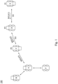
- Fig. 1 is a schematic diagram of a V2X system 100 according to some embodiments of the present disclosure.
- the V2X system 100 includes vehicles (devices) A, B, C, D, E, F. Vehicles can send or receive messages to each other through network communication.
- the detailed operation method of V2X system 100 will be described below with other figures.
- the number of vehicles in the V2X system 100 in Fig. 1 is for illustration only, and the embodiments of the present disclosure are not limited thereto.
- each of the vehicles A, B, C, D, E, F can also be a mobile station or a RSU or any other device in V2X wireless communication system.
- each of the vehicles(devices) A, B, C, D, E, F includes a vehicle name or a device name.
- the vehicles B, C, D, E, F are the several devices surround the vehicle A which can receive a collective perception message from the vehicle A.
- the vehicles B, C, F nearest to the vehicle A are the several devices surround the vehicle A which can receive a collective perception message from the vehicle A.
- vehicle D is one of the several devices surround the vehicle E (a transmitting device transmitting a first collective perception message) and the vehicle D receives the first collective perception message from the vehicle E; and the vehicle C (a receiving device receiving a second collective perception message) is one of the several devices surround the vehicle D and the vehicle D transmits the second collective perception message to the vehicle C according to the received first collective perception message from vehicle E (in other words, vehicle C receives the second collective perception message from vehicle D).
- vehicle E transmits a first collective perception message to several devices, including the vehicle D, surround the vehicle E; and each of the several devices, including the vehicle D, surround the vehicle E transmits a second collective perception message according to the received first collective perception message from the vehicle E to several devices, including the vehicle C, surround the vehicle D.
- Fig. 2 is a schematic diagram of a vehicle 200 according to some embodiments of the present disclosure.
- the vehicle 200 shown in Fig. 2 can be configured to represent the vehicles A, B, C, D, E, F in Fig. 1 .
- the vehicle 200 includes a sensor 210, a processor 230 and a wireless transceiver 250.
- the sensor 210 is coupled to the processor 230
- the processor 230 is further coupled to the wireless transceiver 250.
- the detailed operation method of the vehicle 200 will be described below with other figures.
- the vehicle 200 as illustrated in Fig. 2 is for illustrative purposes only, and the embodiments of the present disclosure are not limited thereto.
- Fig. 3 is a flow chart of an information transmission method 300 according to some embodiments of the present disclosure. The embodiments of the present disclosure are not limited thereto.
- the information transmission method 300 can be applied to a system with the same or similar structure as the V2X 100 in Fig. 1 or a device with the same or similar structure as the vehicle 200 in Fig. 2 .
- the following will take Fig. 1 and Fig. 2 as examples to describe the operation method, however, the embodiments of the present disclosure are not limited thereto.
- the information transmission method 300 can also be implemented as a computer program and stored in a non-transitory computer-readable medium, And make the computer, electronic device, or the aforementioned processor 230 in Fig. 2 read the recording medium and execute the operation method.
- the processor 230 may include one or more wafers.
- the non-transitory computer-readable recording medium may be read-only memory, flash memory, floppy disk, hard disk, compact disc, pen drive, magnetic tape, a database accessible over a network, or a non-transitory computer-readable recording media with the same function that a person skilled in the art can easily think of.
- these operations can also be adaptively added, replaced, and/or omitted.
- the information transmission method 300 includes operations S310 and S330.
- a first collective perception message is generated by a first vehicle according to a perceived object, in which the first collective perception message includes the first object age.
- the operation S310 can be performed by the processor 230 as shown in Fig. 2 .
- operation S330 the first collective perception message is received by the second vehicle, and a second object age of the perceived object is calculated, in which the second object age includes the first object age and the processing delay of the second vehicle, further, the second object age may also include the transmission delay transmitted from the first vehicle to the second vehicle.
- operation S330 can be performed by the processor 230 as shown in Fig. 2 .
- the information transmission method 300 includes the vehicle E sensing the environment to obtain information of perceived objects (such as pedestrians) in the environment. Next, after the vehicle E generates the collective perception message according to the perceived object, it transmits the collective perception message to the vehicle D.
- perceived objects such as pedestrians
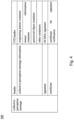
- Fig. 4 is a schematic diagram of a collective perception message 400 according to some embodiments of the present disclosure.
- the collective perception message 400 includes the header, the collective perception message information, the signature, the certificate, etc.
- the collective perception message information further includes the originating station container, the sensor information container, the perceived object container, and other container, etc. It should be noted that, In Fig. 1 , for ease of understanding, the collective perception message 400 described in Fig. 4 will be described with the labels M1 and M2 as its codes.
- the vehicle E when the vehicle E senses the environment to obtain the measurement information of a perceived object, the vehicle E generates a collective perception message M1 accordingly.
- the sensor information container of the collective perception message M1 includes an originating station ID to include the device name of vehicle E.
- the device name of the vehicle E can be regarded as an originating device name.
- the originating station ID refers to the ID of the vehicle where the sensor that detected the perceived object is located. Since the information of the perceived objects (such as pedestrians) in the collective perception message M1 is sensed by the vehicle E, the originating station ID includes the device name of the vehicle E, and the name of the vehicle E can be regarded as the originating device name.
- the information can be prevented from being transmitted back to the originating station.
- the vehicle when the vehicle is transmitting the collective perception messages to another vehicle in the V2X system, the vehicle avoids transmitting the messages to the originating station ID vehicle. In this way, the situation of the collective perception messages being repeatedly sent back to the originating vehicle is avoided.
- the vehicle receives a collective perception message from another vehicle in the V2X system, if the originating station ID in the collective perception message is the same as the vehicle ID, the vehicle avoids receiving the collective perception message or discards the received collective perception message. In this way, the situation of the collective perception messages being repeatedly sent back to the originating vehicle is avoided.
- the perceived object container further includes the object age of the perceived object.
- the object age A1 of the perceived object of the collective perception message M1 generated by the vehicle E includes the processing delay P1 of the vehicle E.
- the processing delay P1 of the vehicle E refers to the time difference between the time that the vehicle E senses the perceived object and the time that the vehicle E transmits the collective perception message M1.
- the object age A1 of the perceived object of the collective perception message M1 generated by the vehicle E can be the processing delay P1 of the vehicle E, or zero, or blank.
- the sensor information container includes the location information when the vehicle E transmits the collective perception message M1, or the location information when the vehicle E obtains the measurement information of the perceived object, or any location information during the period between the vehicle E obtaining the measurement information of the perceived object and transmitting the collective perception message M1.
- the location information is the coordinate information obtained by the vehicle E through GPS satellites and/or the wireless communication networks such as 5G.
- the vehicle D After the vehicle D receives the collective perception message M1, the vehicle D calculates the object age A2 of the perceived object of the collective perception message M2 according to the collective perception message M1.
- the object age A2 is the object age A1 plus the processing delay P2 of the vehicle D.
- the object age A2 is the processing delay P1 of the vehicle E plus the processing delay P2 of the vehicle D.
- the vehicle D can then use the distance between the location information of the collective perception message M1 sent by the vehicle E and the location information when the vehicle D receives the collective perception message M1, so as to calculate the transmission delay D1 of the vehicle E transmitting the collective perception message M1 to the vehicle D. Accordingly, the vehicle D calculates the object age A2 of the perceived object of the collective perception message M2 as the object age A1, plus the transmission delay D1, and then plus the processing delay P2.
- the object age A2 is the processing delay P1 of the vehicle E, plus the transmission delay D1 of the vehicle E transmitting to the vehicle D, and then plus the processing delay P2 of the vehicle D.
- the vehicle D since the transmission delay D1 from the vehicle E to the vehicle D is much smaller than the processing delay P2 of the vehicle D or the processing delay P1 of the vehicle E, therefore, the vehicle D does not count the transmission delay D1 into the calculation of the object age A2 of the perceived object of the collective perception message M2.
- the transmission delay is calculated according to the distance between the vehicles, and the processing delay is calculated by the vehicle itself according to the message processing time of the vehicle itself.
- the embodiments of the present disclosure solves the problem of inaccurate time synchronization between different vehicles.
- the vehicle D generates the collective perception message M2 according to the perceived object information of the collective perception message M1 and transmits the collective perception message M2 to the vehicle C.
- the originating station ID in the sensor information container in the collective perception message M2 includes the device name of the vehicle E.
- the perceived object container in the collective perception message M2 includes the object age A2 of the perceived object.
- the object age A1 of the perceived object of the collective perception message M1 generated by the vehicle E includes the processing delay P1 of the vehicle E.
- the processing delay P1 of the vehicle E refers to the time difference between when the vehicle E senses the perceived object and when the vehicle E transmits the collective perception message M1.
- the vehicle D generates the collective perception message M2 according to the collective perception message M1, and the perceived object container in collective perception message M2 includes the object age A2 of the perceived object.
- the object age A2 is equal to the object age A1 (also P1) plus the processing delay P2, that is, P1+P2.
- the object age A2 is equal to the object age A1 (also P1) plus D1 and then the processing delay P2, which is P1+D1+P2.
- the sensor information container includes the location information when the vehicle D transmits the collective perception message M2, or the location information when the vehicle D receives the collective perception message M1, or any location information during the period between the vehicle D receiving the collective perception message M1 and the vehicle D transmitting the collective perception message M2.
- the location information is the coordinate information obtained by the vehicle D through the GPS satellites and/or the wireless communication networks such as 5G.
- the vehicle C calculates that the transmission delay from the vehicle D transmitting the collective perception message M2 to the vehicle C is D2.
- the vehicle C calculates the object age A3 of the perceived object of the collective perception message M3 as the object age A2 plus the processing delay P3 of vehicle C
- the object age A3 is the processing delay P1 of the vehicle E, plus the processing delay P2 of the vehicle D, plus the processing delay P3 of the vehicle C.
- the object age A3 is the object age A2 plus the processing delay P3 of the vehicle C, plus the transmission delay D2 of the vehicle D to the vehicle C.
- the object age A3 is the processing delay P1 of the vehicle E plus the transmission delay D1 of the transmission from the vehicle E to the vehicle D, plus the processing delay P2 of the vehicle D, plus the transmission delay D2 of the transmission from the vehicle D to the vehicle C, and plus the processing delay P3 of the vehicle C.
- the remaining vehicles calculates the latest object age of the perceived object according to the transmission delay of the transmission path before receiving the collective perception message and the processing delay of each vehicle.
- the vehicle D when the vehicle D receives the collective perception message M1 and obtains the object age A1 of the perceived object, if the object age A1 is larger than the first default value, the vehicle D discards the collective perception message M1, and will not transmit the perceived object in this message to other vehicles. If the vehicle D determines that the object age A1 is not larger than a first default value, the vehicle D will continue to send the perceived object in the message to other vehicles. In this way, the infinite flood of old messages in the V2X system can be avoided.
- the vehicle D when vehicle D is generating the collective perception message M2 and calculating object age A2 of the perceived object, if object age A2 is larger than a second default value, the vehicle D will not generate or will discard collective perception message M2, and will not transmit the perceived objects in this message to other vehicles. If the vehicle D determines that the object age A2 is not larger than a second default value, the vehicle D will continue to send the perceived object in the message to other vehicles. In this way, the infinite flood of old messages in the V2X system can be avoided.
- the first default value is different from the second default value. In some embodiments, the first default value is the same as the second default value.
- the senor 210 can be a circuit or other element with an environment sensing function.
- the processor 230 can be a server, a circuit, a central processing unit (CPU), a micro-decoder (MCU) or other equivalent devices with functions such as temporary storage, operation, data reading, receiving signals or messages, transmitting signals or messages or equivalent functions.
- the wireless transceiver 250 can be an arithmetic circuit or element with data reading, transmission and reception, or similar functions.
- the embodiment of the present disclosure is to provide an information transmission method, a V2X system and a vehicle, the calculation of the object age of the perceived object are based on the transmission delay and/or the processing delay, which solves the problem of inaccurate time synchronization between different vehicles. Furthermore, since the originating station container in the collective perception message includes the information of the vehicle, the repeated transmission of the message back to the originating vehicle can be avoided.
Landscapes
- Engineering & Computer Science (AREA)
- Computer Networks & Wireless Communication (AREA)
- Signal Processing (AREA)
- Automation & Control Theory (AREA)
- Transportation (AREA)
- Mechanical Engineering (AREA)
- Human Computer Interaction (AREA)
- Traffic Control Systems (AREA)
- Mobile Radio Communication Systems (AREA)
Claims (11)
- Vorrichtung (D), die für ein V2X-, Vehicle-to-Everything-, System (100) geeignet ist, mit:einem drahtlosen Transceiver (250), der konfiguriert ist, eine erste kollektive Wahrnehmungsnachricht (M1) von einer Sendevorrichtung (E) des V2X-Systems (100) zu empfangen, wobei die erste kollektive Wahrnehmungsnachricht (M1) ein erstes Objektalter (A1) eines wahrgenommenen Objekts der ersten kollektiven Wahrnehmungsnachricht (M1) aufweist, das durch die Sendevorrichtung (E) berechnet wird; undeinem Prozessor (230), der mit dem drahtlosen Transceiver (250) gekoppelt ist, und dadurch gekennzeichnet ist, dass er konfiguriert ist, ein zweites Objektalter (A2) des wahrgenommenen Objekts für eine zweite kollektive Wahrnehmungsnachricht (M2) zu berechnen, wobei die zweite kollektive Wahrnehmungsnachricht (M2) durch die Vorrichtung (D) gemäß der ersten kollektiven Wahrnehmungsnachricht (M1) erzeugt wird, und wobei das zweite Objektalter (A2) eine Verarbeitungsverzögerung (P2) der Vorrichtung (D) und das erste Objektalter (A1) aufweist.
- Vorrichtung (D) nach Anspruch 1, wobei eine Mehrzahl von Vorrichtungen, einschließlich der Vorrichtung (D), die die Sendevorrichtung (E) umgibt, die erste kollektive Wahrnehmungsnachricht (M1) von der Sendevorrichtung (E) mit einem Sidelink-Verfahren empfängt.
- Vorrichtung (D) nach Anspruch 1 oder 2, wobei der Prozessor (230) ferner konfiguriert ist, eine erste Sendeverzögerung (D1) gemäß einer Ortsinformation der Sendevorrichtung (E) der ersten kollektiven Wahrnehmungsnachricht (M1) und einer Ortsinformation der Vorrichtung (D) zu berechnen, wobei das zweite Objektalter (A2) ferner die erste Sendeverzögerung (D1) aufweist.
- Vorrichtung (D) nach Anspruch 1 oder 3, wobei die Vorrichtung (D) ferner die zweite kollektive Wahrnehmungsnachricht (M2) an eine Mehrzahl von Vorrichtungen, einschließlich einer Empfangsvorrichtung (C), die die Vorrichtung (D) umgibt, mit einem Sidelink-Verfahren sendet.
- Vorrichtung (D) nach einem der Ansprüche 1 bis 4, wobei die erste kollektive Wahrnehmungsnachricht (M1) einen Sensorinformationsbehälter aufweist, wobei der Sensorinformationsbehälter einen Ursprungsvorrichtungsnamen einer Ursprungsvorrichtung aufweist, die das wahrgenommene Objekt erzeugt;
wobei, wenn ein Vorrichtungsname der Vorrichtung (D) und der Ursprungsvorrichtungsname der Ursprungsvorrichtung des wahrgenommenen Objekts gleich sind, die Vorrichtung die erste kollektive Wahrnehmungsnachricht nicht empfängt oder die empfangene erste kollektive Wahrnehmungsnachricht verwirft. - Verfahren (300), das durch eine Vorrichtung (D) eines V2X-Systems (100) durchgeführt wird, mit:Empfangen einer ersten kollektiven Wahrnehmungsnachricht (M1) von einer Sendevorrichtung (E) des V2X-Systems (100) durch einen drahtlosen Transceiver (250), wobei die erste kollektive Wahrnehmungsnachricht (M1) ein erstes Objektalter (A1) eines wahrgenommenen Objekts der ersten kollektiven Wahrnehmungsnachricht (M1) aufweist, das durch die Sendevorrichtung (E) berechnet wird; und gekennzeichnet durchBerechnen eines zweiten Objektalters (A2) des wahrgenommenen Objekts für eine zweite kollektive Wahrnehmungsnachricht (M2) durch einen Prozessor (230) der Vorrichtung (D), wobei der Prozessor (230) der Vorrichtung (D) mit dem drahtlosen Transceiver (250) gekoppelt ist, wobei die zweite kollektive Wahrnehmungsnachricht (M2) durch die Vorrichtung (D) gemäß der ersten kollektiven Wahrnehmungsnachricht (M1) erzeugt wird, und wobei das zweite Objektalter (A2) eine Verarbeitungsverzögerung (P2) der Vorrichtung (D) und das erste Objektalter (A1) aufweist.
- Verfahren (300) nach Anspruch 6, ferner mit:
Berechnen einer ersten Sendeverzögerung (D1) gemäß einer Ortsinformation der Sendevorrichtung (E) der ersten kollektiven Wahrnehmungsnachricht (M1) und einer Ortsinformation der Vorrichtung (D) durch den Prozessor (230) der Vorrichtung (D), wobei das zweite Objektalter (A2) ferner die erste Sendeverzögerung (D1) aufweist. - Verfahren (300) nach Anspruch 6 oder 7, wobei die erste kollektive Wahrnehmungsnachricht (M1) einen Sensorinformationsbehälter aufweist, wobei der Sensorinformationsbehälter einen Ursprungsvorrichtungsnamen einer Ursprungsvorrichtung aufweist, die das wahrgenommene Objekt erzeugt.
- Verfahren (300) nach Anspruch 8, wobei, wenn ein Vorrichtungsname der Vorrichtung (D) und der Ursprungsvorrichtungsname der Ursprungsvorrichtung des wahrgenommenen Objekts gleich sind, die Vorrichtung (D) die erste kollektive Wahrnehmungsnachricht (M1) nicht empfängt oder die empfangene erste kollektive Wahrnehmungsnachricht (M1) verwirft.
- Verfahren (300) nach einem der Ansprüche 6 bis 9, wobei, wenn das erste Objektalter (A1) größer als ein erster Standardwert ist, die erste kollektive Wahrnehmungsnachricht (M1) verworfen wird; und wobei, wenn das erste Objektalter (A1) nicht größer als der erste Standardwert ist, die zweite kollektive Wahrnehmungsnachricht (M2) gemäß der ersten kollektiven Wahrnehmungsnachricht (M1) erzeugt wird.
- Verfahren (300) nach einem der Ansprüche 6 bis 10, wobei, wenn das zweite Objektalter (A2) größer als ein zweiter Standardwert ist, die zweite kollektive Wahrnehmungsnachricht (M2) verworfen wird;
wobei, wenn das zweite Objektalter (A2) nicht größer als der zweite Standardwert ist, die zweite kollektive Wahrnehmungsnachricht (M2) an eine Mehrzahl von anderen Vorrichtungen, die die Vorrichtung (D) umgeben, mit einem Sidelink-Verfahren durch den Prozessor (230) gesendet wird.
Applications Claiming Priority (3)
| Application Number | Priority Date | Filing Date | Title |
|---|---|---|---|
| TW110145347A TW202325052A (zh) | 2021-12-03 | 2021-12-03 | 用於v2x無線通訊系統的無線通訊裝置及路側設備(rsu) |
| US202163265292P | 2021-12-13 | 2021-12-13 | |
| TW111117180A TWI810924B (zh) | 2021-12-13 | 2022-05-06 | 適用於v2x系統的裝置及車輛 |
Publications (3)
| Publication Number | Publication Date |
|---|---|
| EP4192052A1 EP4192052A1 (de) | 2023-06-07 |
| EP4192052B1 true EP4192052B1 (de) | 2025-06-25 |
| EP4192052C0 EP4192052C0 (de) | 2025-06-25 |
Family
ID=82557932
Family Applications (1)
| Application Number | Title | Priority Date | Filing Date |
|---|---|---|---|
| EP22187169.2A Active EP4192052B1 (de) | 2021-12-03 | 2022-07-27 | Vorrichtung, fahrzeug und verfahren für v2x system |
Country Status (2)
| Country | Link |
|---|---|
| US (1) | US12128926B2 (de) |
| EP (1) | EP4192052B1 (de) |
Family Cites Families (10)
| Publication number | Priority date | Publication date | Assignee | Title |
|---|---|---|---|---|
| US9759574B2 (en) | 2015-07-14 | 2017-09-12 | Ford Global Technologes, Llc | Vehicle emergency broadcast and relay |
| CN108028710B (zh) | 2015-09-15 | 2019-12-24 | 华为技术有限公司 | 传输通信消息的装置和方法 |
| EP3603293B1 (de) | 2017-03-23 | 2023-03-15 | Apple Inc. | Priorisierte nachrichtenübermittlung und ressourcenauswahl in der vehicle-to-vehicle (v2v)-sidelink-kommunikation |
| KR102334318B1 (ko) | 2017-09-19 | 2021-12-03 | 삼성전자주식회사 | 외부 이동 수단으로 릴레이 메시지를 전송하는 전자 장치 및 그 동작 방법 |
| US11432135B2 (en) | 2018-06-19 | 2022-08-30 | Apple Inc. | Vehicle-to-everything (V2X) control function based on user equipment (UE) capability |
| FR3095733B1 (fr) | 2019-04-30 | 2021-10-22 | Renault Sas | Systeme et procede de gestion de communication v2x entre un vehicule et un dispositif recepteur |
| EP3737123A1 (de) | 2019-05-06 | 2020-11-11 | Volkswagen Aktiengesellschaft | Vorrichtung, verfahren und computerprogramm zur bestimmung einer oder mehrerer funkressourcen zur verwendung zur durchführung einer drahtlosen kommunikation über einen sidelink eines mobilkommunikationssystems |
| US11593344B2 (en) * | 2019-07-02 | 2023-02-28 | Nvidia Corporation | Updating high definition maps based on age of maps |
| KR102885638B1 (ko) | 2019-11-22 | 2025-11-13 | 삼성전자 주식회사 | V2x 메시지를 처리하기 위한 전자 장치 및 그의 동작 방법 |
| CN112911555B (zh) | 2021-01-28 | 2022-03-25 | 上海交通大学 | 基于信息年龄的无线网络通信资源调度方法和系统 |
-
2022
- 2022-06-14 US US17/806,938 patent/US12128926B2/en active Active
- 2022-07-27 EP EP22187169.2A patent/EP4192052B1/de active Active
Also Published As
| Publication number | Publication date |
|---|---|
| EP4192052A1 (de) | 2023-06-07 |
| US20230174104A1 (en) | 2023-06-08 |
| US12128926B2 (en) | 2024-10-29 |
| EP4192052C0 (de) | 2025-06-25 |
Similar Documents
| Publication | Publication Date | Title |
|---|---|---|
| US11776405B2 (en) | Apparatus and method for V2X communication | |
| EP3462754B1 (de) | Vorrichtung und verfahren zur v2x-kommunikation | |
| Malinverno et al. | Edge-based collision avoidance for vehicles and vulnerable users: An architecture based on MEC | |
| EP3691300B1 (de) | Vorrichtung und verfahren für v2x-kommunikation | |
| WO2017135036A1 (en) | Electronic devices and method for direct communication | |
| US9723451B2 (en) | Providing location information of a terminal in a communication network | |
| EP4021052B1 (de) | Erkennung von fehlverhalten eines vertrauenswürdigen agenten durch streuverlustabfall | |
| CN108028710B (zh) | 传输通信消息的装置和方法 | |
| AU2020203683B2 (en) | Methods and systems for authenticating an automatic dependent surveillance-broadcast (ADS-B) signal | |
| EP4192052B1 (de) | Vorrichtung, fahrzeug und verfahren für v2x system | |
| US12335839B2 (en) | Electronic device, wireless communication method and computer-readable storage medium | |
| US11032682B2 (en) | Method and apparatus for communication between vehicles and apparatus for using the same | |
| US20210176311A1 (en) | Method and systems for sharing data | |
| JP2018107798A (ja) | 第1の移動通信システムと第2の移動通信システムとの間の干渉を低減するための移動機器のための方法、装置及びコンピュータプログラム | |
| TWI810924B (zh) | 適用於v2x系統的裝置及車輛 | |
| Chen et al. | A lane-level cooperative collision avoidance system based on vehicular sensor networks | |
| CN114333384B (zh) | 通信方法、装置及系统 | |
| CN114882718A (zh) | 适用于v2x系统的装置及车辆 | |
| TWI827390B (zh) | 適用於v2x系統的電子裝置及訊息傳送方法 | |
| CN107343256B (zh) | 一种网络覆盖受限场景下的车辆间通信方法 | |
| JP6738945B1 (ja) | 通信装置、通信システム及び通信装置のプログラム | |
| EP4387281A1 (de) | Verbesserte cluster-breakup-verwaltung in einem intelligenten transportsystem | |
| US20250184699A1 (en) | Multi-access edge computing-based specific relative-speed service | |
| CN118158635A (zh) | 适用于v2x系统的装置及信息传送方法 | |
| EP4167607A1 (de) | Kooperatives intelligentes transportsystem und verfahren mit cpm-informationssignifikanzniveau |
Legal Events
| Date | Code | Title | Description |
|---|---|---|---|
| PUAI | Public reference made under article 153(3) epc to a published international application that has entered the european phase |
Free format text: ORIGINAL CODE: 0009012 |
|
| STAA | Information on the status of an ep patent application or granted ep patent |
Free format text: STATUS: REQUEST FOR EXAMINATION WAS MADE |
|
| 17P | Request for examination filed |
Effective date: 20220727 |
|
| AK | Designated contracting states |
Kind code of ref document: A1 Designated state(s): AL AT BE BG CH CY CZ DE DK EE ES FI FR GB GR HR HU IE IS IT LI LT LU LV MC MK MT NL NO PL PT RO RS SE SI SK SM TR |
|
| STAA | Information on the status of an ep patent application or granted ep patent |
Free format text: STATUS: EXAMINATION IS IN PROGRESS |
|
| 17Q | First examination report despatched |
Effective date: 20240118 |
|
| GRAP | Despatch of communication of intention to grant a patent |
Free format text: ORIGINAL CODE: EPIDOSNIGR1 |
|
| STAA | Information on the status of an ep patent application or granted ep patent |
Free format text: STATUS: GRANT OF PATENT IS INTENDED |
|
| INTG | Intention to grant announced |
Effective date: 20250227 |
|
| GRAS | Grant fee paid |
Free format text: ORIGINAL CODE: EPIDOSNIGR3 |
|
| GRAA | (expected) grant |
Free format text: ORIGINAL CODE: 0009210 |
|
| STAA | Information on the status of an ep patent application or granted ep patent |
Free format text: STATUS: THE PATENT HAS BEEN GRANTED |
|
| RAP3 | Party data changed (applicant data changed or rights of an application transferred) |
Owner name: HON HAI PRECISION INDUSTRY CO., LTD. |
|
| RIN1 | Information on inventor provided before grant (corrected) |
Inventor name: CHANG, KE-PING Inventor name: HUANG, YU-KAI |
|
| AK | Designated contracting states |
Kind code of ref document: B1 Designated state(s): AL AT BE BG CH CY CZ DE DK EE ES FI FR GB GR HR HU IE IS IT LI LT LU LV MC MK MT NL NO PL PT RO RS SE SI SK SM TR |
|
| REG | Reference to a national code |
Ref country code: GB Ref legal event code: FG4D |
|
| REG | Reference to a national code |
Ref country code: CH Ref legal event code: EP |
|
| REG | Reference to a national code |
Ref country code: CH Ref legal event code: EP |
|
| REG | Reference to a national code |
Ref country code: IE Ref legal event code: FG4D |
|
| REG | Reference to a national code |
Ref country code: DE Ref legal event code: R096 Ref document number: 602022016333 Country of ref document: DE |
|
| U01 | Request for unitary effect filed |
Effective date: 20250722 |
|
| U07 | Unitary effect registered |
Designated state(s): AT BE BG DE DK EE FI FR IT LT LU LV MT NL PT RO SE SI Effective date: 20250728 |
|
| PG25 | Lapsed in a contracting state [announced via postgrant information from national office to epo] |
Ref country code: NO Free format text: LAPSE BECAUSE OF FAILURE TO SUBMIT A TRANSLATION OF THE DESCRIPTION OR TO PAY THE FEE WITHIN THE PRESCRIBED TIME-LIMIT Effective date: 20250925 Ref country code: GR Free format text: LAPSE BECAUSE OF FAILURE TO SUBMIT A TRANSLATION OF THE DESCRIPTION OR TO PAY THE FEE WITHIN THE PRESCRIBED TIME-LIMIT Effective date: 20250926 |
|
| PG25 | Lapsed in a contracting state [announced via postgrant information from national office to epo] |
Ref country code: HR Free format text: LAPSE BECAUSE OF FAILURE TO SUBMIT A TRANSLATION OF THE DESCRIPTION OR TO PAY THE FEE WITHIN THE PRESCRIBED TIME-LIMIT Effective date: 20250625 |
|
| PG25 | Lapsed in a contracting state [announced via postgrant information from national office to epo] |
Ref country code: RS Free format text: LAPSE BECAUSE OF FAILURE TO SUBMIT A TRANSLATION OF THE DESCRIPTION OR TO PAY THE FEE WITHIN THE PRESCRIBED TIME-LIMIT Effective date: 20250925 |
|
| U20 | Renewal fee for the european patent with unitary effect paid |
Year of fee payment: 4 Effective date: 20251001 |
|
| PG25 | Lapsed in a contracting state [announced via postgrant information from national office to epo] |
Ref country code: IS Free format text: LAPSE BECAUSE OF FAILURE TO SUBMIT A TRANSLATION OF THE DESCRIPTION OR TO PAY THE FEE WITHIN THE PRESCRIBED TIME-LIMIT Effective date: 20251025 |
|
| PG25 | Lapsed in a contracting state [announced via postgrant information from national office to epo] |
Ref country code: SM Free format text: LAPSE BECAUSE OF FAILURE TO SUBMIT A TRANSLATION OF THE DESCRIPTION OR TO PAY THE FEE WITHIN THE PRESCRIBED TIME-LIMIT Effective date: 20250625 |
|
| PG25 | Lapsed in a contracting state [announced via postgrant information from national office to epo] |
Ref country code: CZ Free format text: LAPSE BECAUSE OF FAILURE TO SUBMIT A TRANSLATION OF THE DESCRIPTION OR TO PAY THE FEE WITHIN THE PRESCRIBED TIME-LIMIT Effective date: 20250625 |
|
| PG25 | Lapsed in a contracting state [announced via postgrant information from national office to epo] |
Ref country code: PL Free format text: LAPSE BECAUSE OF FAILURE TO SUBMIT A TRANSLATION OF THE DESCRIPTION OR TO PAY THE FEE WITHIN THE PRESCRIBED TIME-LIMIT Effective date: 20250625 |
|
| PG25 | Lapsed in a contracting state [announced via postgrant information from national office to epo] |
Ref country code: SK Free format text: LAPSE BECAUSE OF FAILURE TO SUBMIT A TRANSLATION OF THE DESCRIPTION OR TO PAY THE FEE WITHIN THE PRESCRIBED TIME-LIMIT Effective date: 20250625 |
|
| PG25 | Lapsed in a contracting state [announced via postgrant information from national office to epo] |
Ref country code: ES Free format text: LAPSE BECAUSE OF FAILURE TO SUBMIT A TRANSLATION OF THE DESCRIPTION OR TO PAY THE FEE WITHIN THE PRESCRIBED TIME-LIMIT Effective date: 20250625 |