EP4192009A1 - Procédé et appareil de codage/décodage de mode de prédiction intra - Google Patents
Procédé et appareil de codage/décodage de mode de prédiction intra Download PDFInfo
- Publication number
- EP4192009A1 EP4192009A1 EP23153916.4A EP23153916A EP4192009A1 EP 4192009 A1 EP4192009 A1 EP 4192009A1 EP 23153916 A EP23153916 A EP 23153916A EP 4192009 A1 EP4192009 A1 EP 4192009A1
- Authority
- EP
- European Patent Office
- Prior art keywords
- candidate
- mode
- modes
- intra
- prediction
- Prior art date
- Legal status (The legal status is an assumption and is not a legal conclusion. Google has not performed a legal analysis and makes no representation as to the accuracy of the status listed.)
- Pending
Links
- 238000000034 method Methods 0.000 title claims abstract description 207
- 238000005070 sampling Methods 0.000 claims description 14
- 230000001174 ascending effect Effects 0.000 claims description 9
- 238000013139 quantization Methods 0.000 description 40
- 238000005192 partition Methods 0.000 description 28
- 238000010586 diagram Methods 0.000 description 23
- 239000011159 matrix material Substances 0.000 description 20
- 230000008569 process Effects 0.000 description 19
- 208000037170 Delayed Emergence from Anesthesia Diseases 0.000 description 14
- 239000000523 sample Substances 0.000 description 14
- 238000009826 distribution Methods 0.000 description 12
- FZEIVUHEODGHML-UHFFFAOYSA-N 2-phenyl-3,6-dimethylmorpholine Chemical compound O1C(C)CNC(C)C1C1=CC=CC=C1 FZEIVUHEODGHML-UHFFFAOYSA-N 0.000 description 11
- 230000009466 transformation Effects 0.000 description 11
- 230000003044 adaptive effect Effects 0.000 description 10
- 238000000638 solvent extraction Methods 0.000 description 10
- 238000005516 engineering process Methods 0.000 description 8
- 239000000470 constituent Substances 0.000 description 7
- 238000001914 filtration Methods 0.000 description 7
- 230000006870 function Effects 0.000 description 6
- 230000001131 transforming effect Effects 0.000 description 5
- 241000209094 Oryza Species 0.000 description 4
- 235000007164 Oryza sativa Nutrition 0.000 description 4
- 238000010276 construction Methods 0.000 description 4
- 238000012986 modification Methods 0.000 description 4
- 230000004048 modification Effects 0.000 description 4
- 235000009566 rice Nutrition 0.000 description 4
- 241000023320 Luma <angiosperm> Species 0.000 description 3
- 230000006978 adaptation Effects 0.000 description 3
- 230000006835 compression Effects 0.000 description 3
- 238000007906 compression Methods 0.000 description 3
- OSWPMRLSEDHDFF-UHFFFAOYSA-N methyl salicylate Chemical compound COC(=O)C1=CC=CC=C1O OSWPMRLSEDHDFF-UHFFFAOYSA-N 0.000 description 3
- 230000002441 reversible effect Effects 0.000 description 3
- QEDQZYNGDXULGO-UHFFFAOYSA-N 3-methyl-2-(3-methylphenyl)morpholine Chemical compound CC1NCCOC1C1=CC=CC(C)=C1 QEDQZYNGDXULGO-UHFFFAOYSA-N 0.000 description 2
- 230000005540 biological transmission Effects 0.000 description 2
- 230000008859 change Effects 0.000 description 2
- 239000013074 reference sample Substances 0.000 description 2
- 230000004044 response Effects 0.000 description 2
- 230000011664 signaling Effects 0.000 description 2
- 230000002123 temporal effect Effects 0.000 description 2
- 101100129500 Caenorhabditis elegans max-2 gene Proteins 0.000 description 1
- 238000013500 data storage Methods 0.000 description 1
- 230000000694 effects Effects 0.000 description 1
- 230000006872 improvement Effects 0.000 description 1
- 230000003287 optical effect Effects 0.000 description 1
- 238000005457 optimization Methods 0.000 description 1
- 229920006395 saturated elastomer Polymers 0.000 description 1
Images


Classifications
-
- H—ELECTRICITY
- H04—ELECTRIC COMMUNICATION TECHNIQUE
- H04N—PICTORIAL COMMUNICATION, e.g. TELEVISION
- H04N19/00—Methods or arrangements for coding, decoding, compressing or decompressing digital video signals
- H04N19/10—Methods or arrangements for coding, decoding, compressing or decompressing digital video signals using adaptive coding
- H04N19/102—Methods or arrangements for coding, decoding, compressing or decompressing digital video signals using adaptive coding characterised by the element, parameter or selection affected or controlled by the adaptive coding
- H04N19/103—Selection of coding mode or of prediction mode
-
- H—ELECTRICITY
- H04—ELECTRIC COMMUNICATION TECHNIQUE
- H04N—PICTORIAL COMMUNICATION, e.g. TELEVISION
- H04N19/00—Methods or arrangements for coding, decoding, compressing or decompressing digital video signals
- H04N19/50—Methods or arrangements for coding, decoding, compressing or decompressing digital video signals using predictive coding
- H04N19/593—Methods or arrangements for coding, decoding, compressing or decompressing digital video signals using predictive coding involving spatial prediction techniques
-
- H—ELECTRICITY
- H04—ELECTRIC COMMUNICATION TECHNIQUE
- H04N—PICTORIAL COMMUNICATION, e.g. TELEVISION
- H04N19/00—Methods or arrangements for coding, decoding, compressing or decompressing digital video signals
- H04N19/10—Methods or arrangements for coding, decoding, compressing or decompressing digital video signals using adaptive coding
- H04N19/102—Methods or arrangements for coding, decoding, compressing or decompressing digital video signals using adaptive coding characterised by the element, parameter or selection affected or controlled by the adaptive coding
- H04N19/103—Selection of coding mode or of prediction mode
- H04N19/105—Selection of the reference unit for prediction within a chosen coding or prediction mode, e.g. adaptive choice of position and number of pixels used for prediction
-
- H—ELECTRICITY
- H04—ELECTRIC COMMUNICATION TECHNIQUE
- H04N—PICTORIAL COMMUNICATION, e.g. TELEVISION
- H04N19/00—Methods or arrangements for coding, decoding, compressing or decompressing digital video signals
- H04N19/10—Methods or arrangements for coding, decoding, compressing or decompressing digital video signals using adaptive coding
- H04N19/102—Methods or arrangements for coding, decoding, compressing or decompressing digital video signals using adaptive coding characterised by the element, parameter or selection affected or controlled by the adaptive coding
- H04N19/103—Selection of coding mode or of prediction mode
- H04N19/11—Selection of coding mode or of prediction mode among a plurality of spatial predictive coding modes
-
- H—ELECTRICITY
- H04—ELECTRIC COMMUNICATION TECHNIQUE
- H04N—PICTORIAL COMMUNICATION, e.g. TELEVISION
- H04N19/00—Methods or arrangements for coding, decoding, compressing or decompressing digital video signals
- H04N19/10—Methods or arrangements for coding, decoding, compressing or decompressing digital video signals using adaptive coding
- H04N19/134—Methods or arrangements for coding, decoding, compressing or decompressing digital video signals using adaptive coding characterised by the element, parameter or criterion affecting or controlling the adaptive coding
- H04N19/146—Data rate or code amount at the encoder output
-
- H—ELECTRICITY
- H04—ELECTRIC COMMUNICATION TECHNIQUE
- H04N—PICTORIAL COMMUNICATION, e.g. TELEVISION
- H04N19/00—Methods or arrangements for coding, decoding, compressing or decompressing digital video signals
- H04N19/10—Methods or arrangements for coding, decoding, compressing or decompressing digital video signals using adaptive coding
- H04N19/134—Methods or arrangements for coding, decoding, compressing or decompressing digital video signals using adaptive coding characterised by the element, parameter or criterion affecting or controlling the adaptive coding
- H04N19/157—Assigned coding mode, i.e. the coding mode being predefined or preselected to be further used for selection of another element or parameter
- H04N19/159—Prediction type, e.g. intra-frame, inter-frame or bidirectional frame prediction
-
- H—ELECTRICITY
- H04—ELECTRIC COMMUNICATION TECHNIQUE
- H04N—PICTORIAL COMMUNICATION, e.g. TELEVISION
- H04N19/00—Methods or arrangements for coding, decoding, compressing or decompressing digital video signals
- H04N19/10—Methods or arrangements for coding, decoding, compressing or decompressing digital video signals using adaptive coding
- H04N19/134—Methods or arrangements for coding, decoding, compressing or decompressing digital video signals using adaptive coding characterised by the element, parameter or criterion affecting or controlling the adaptive coding
- H04N19/167—Position within a video image, e.g. region of interest [ROI]
-
- H—ELECTRICITY
- H04—ELECTRIC COMMUNICATION TECHNIQUE
- H04N—PICTORIAL COMMUNICATION, e.g. TELEVISION
- H04N19/00—Methods or arrangements for coding, decoding, compressing or decompressing digital video signals
- H04N19/10—Methods or arrangements for coding, decoding, compressing or decompressing digital video signals using adaptive coding
- H04N19/169—Methods or arrangements for coding, decoding, compressing or decompressing digital video signals using adaptive coding characterised by the coding unit, i.e. the structural portion or semantic portion of the video signal being the object or the subject of the adaptive coding
- H04N19/17—Methods or arrangements for coding, decoding, compressing or decompressing digital video signals using adaptive coding characterised by the coding unit, i.e. the structural portion or semantic portion of the video signal being the object or the subject of the adaptive coding the unit being an image region, e.g. an object
- H04N19/176—Methods or arrangements for coding, decoding, compressing or decompressing digital video signals using adaptive coding characterised by the coding unit, i.e. the structural portion or semantic portion of the video signal being the object or the subject of the adaptive coding the unit being an image region, e.g. an object the region being a block, e.g. a macroblock
-
- H—ELECTRICITY
- H04—ELECTRIC COMMUNICATION TECHNIQUE
- H04N—PICTORIAL COMMUNICATION, e.g. TELEVISION
- H04N19/00—Methods or arrangements for coding, decoding, compressing or decompressing digital video signals
- H04N19/44—Decoders specially adapted therefor, e.g. video decoders which are asymmetric with respect to the encoder
-
- H—ELECTRICITY
- H04—ELECTRIC COMMUNICATION TECHNIQUE
- H04N—PICTORIAL COMMUNICATION, e.g. TELEVISION
- H04N19/00—Methods or arrangements for coding, decoding, compressing or decompressing digital video signals
- H04N19/46—Embedding additional information in the video signal during the compression process
- H04N19/463—Embedding additional information in the video signal during the compression process by compressing encoding parameters before transmission
-
- H—ELECTRICITY
- H04—ELECTRIC COMMUNICATION TECHNIQUE
- H04N—PICTORIAL COMMUNICATION, e.g. TELEVISION
- H04N19/00—Methods or arrangements for coding, decoding, compressing or decompressing digital video signals
- H04N19/70—Methods or arrangements for coding, decoding, compressing or decompressing digital video signals characterised by syntax aspects related to video coding, e.g. related to compression standards
-
- H—ELECTRICITY
- H04—ELECTRIC COMMUNICATION TECHNIQUE
- H04N—PICTORIAL COMMUNICATION, e.g. TELEVISION
- H04N19/00—Methods or arrangements for coding, decoding, compressing or decompressing digital video signals
- H04N19/90—Methods or arrangements for coding, decoding, compressing or decompressing digital video signals using coding techniques not provided for in groups H04N19/10-H04N19/85, e.g. fractals
- H04N19/91—Entropy coding, e.g. variable length coding [VLC] or arithmetic coding
Definitions
- the present invention relates generally to a method and apparatus for encoding/decoding for signaling an intra prediction mode in an image encoding/decoding.
- Ultra High Definition As broadcasting having High Definition (HD) resolution broadcasting is extended and provided nationwide and worldwide, many users have become accustomed to images having high resolution and high picture quality. Accordingly, many institutions are providing an impetus for the development of the next generation image devices. Furthermore, as there is a growing interest in Ultra High Definition (UHD), which has a resolution for times higher than HDTV, there is a need for technology in which an image having higher resolution and higher picture quality can be compressed and processed.
- UHD Ultra High Definition
- an image compression technology there are various technologies such as an inter-prediction technology in which pixel values included in a current picture are predicted from pictures before or after the current picture, an intra-prediction technology in which pixel values included in a current picture are predicted using pixel information in the current picture, a transformation and quantization technology for compressing energy of residual signals, and an entropy encoding technology in which a short code is allocated to a value having high appearance frequency and a long code is allocated to a value having low appearance frequency.
- the image data may be transmitted and stored in a state in which it is effectively compressed using these image compression technologies.
- an amount of bits required to be transmitted may be increased.
- the amount of bits for intra prediction mode is predicted to occupy a large portion of the total amount of bits, so an improvement plan is required.
- the present invention is intended to propose a method and apparatus for efficiently encoding/decoding an image.
- the present invention provides a method and apparatus for efficiently encoding/decoding an intra-prediction mode.
- the present invention provides a method and apparatus for reducing an amount of bits required for a transmission of an intra-prediction mode.
- the present invention provides a method and apparatus for reducing an amount of bits generated for transmitting intra-prediction modes when an intra-prediction mode of a current encoding block is determined through a rate-distortion optimization process as the number of the intra-prediction modes is increased.
- a method for encoding an image including: a first decision step of determining whether an intra-prediction mode of a current block is included in a first candidate mode set including M candidate modes (M is an integer equal to or greater than 1); a second decision step of determining whether the intra-prediction mode of the current block is included in a second candidate mode set including N candidate modes (N is an integer equal to or greater than 1) based on a first determination result representing a determination result of the first decision step; and an intra prediction mode encoding step of encoding the intra-prediction mode of the current block based on the first determination result or a second determination result representing a determination result of the second decision step.
- the intra prediction mode encoding step may encode result information about the first determination result and first indication information for indicating a candidate mode which is the same as the intra-prediction mode of the current block among the M candidate modes included in the first candidate mode set.
- the intra prediction mode encoding step may encode information about the first determination result, information about the second determination result, and second indication information for indicating a candidate mode which is the same as the intra-prediction mode of the current block among the N candidate modes included in the second candidate mode set.
- the encoding step may encode information about the first determination result, information about the second determination result, and third indication information for indicating a mode which is the same as the intra-prediction mode of the current block among a plurality of modes each of which is not included in either the first candidate mode set or the second candidate mode set.
- the candidate mode included in the second candidate mode set may be determined based on at least one reference prediction mode that is selected from the candidate mode included in the first candidate mode set, and the reference prediction mode may be an angular mode.
- the reference prediction mode may be at least one of a maximum value, a minimum value, an average value, a median value derived from the plurality of the angular modes or an intra-prediction mode derived from an available block adjacent to the current block.
- the candidate mode included in the second candidate mode set may be selected from prediction modes smaller than the reference prediction mode and prediction modes greater than the reference prediction mode according to a predetermined interval.
- the method may further comprise encoding step of encoding information indicating whether the second candidate mode set is used for encoding an intra prediction mode of a block included in the image.
- the method may further comprise encoding of encoding information about the number M indicating the number of candidate modes included in the first candidate mode set or information about the number N indicating the number of candidate modes included in the second candidate mode.
- the method may further comprise an additional decision step, in addition to the first and second decision steps, and the intra prediction mode encoding step may be performed based on a determination result of the additional decision step.
- a method for decoding an image comprising: decoding candidate mode set selecting information and candidate mode selecting information; selecting a candidate mode set based on the candidate mode set selecting information; and selecting one candidate mode among at least one candidate mode included in the candidate mode set based on the candidate mode selecting information as an intra-prediction mode of a current block, wherein the candidate mode set selecting information is information for selecting a candidate mode set used for deriving the intra-prediction mode of the current block among at least one candidate mode set.
- the at least one candidate mode set may include at least one of a first candidate mode set including M candidate modes (M is an integer equal to or greater than 1) and a second candidate mode set including N candidate modes (N is an integer equal to or greater than 1)
- the candidate mode selecting information may be information for indicating one candidate mode among the M candidate modes included in the first candidate mode set.
- the candidate mode selecting information may be information for indicating one candidate mode among the N candidate modes included in the second candidate mode set.
- the candidate mode selecting information may be information for indicating one candidate mode among at least one candidate mode that is not included in either the first or second candidate mode sets.
- the candidate mode included in the second candidate mode set may be determined based on at least one reference prediction mode that is selected from the candidate modes included in the first candidate mode set, and the reference prediction mode may be an angular mode.
- the reference prediction mode may be at least one of a maximum value, a minimum value, an average value, a median value derived from the plurality of the angular modes or an intra-prediction mode derived from an available block adjacent to the current block.
- the candidate mode included in the second candidate mode set may be selected from prediction modes smaller than the reference prediction mode and prediction modes greater than the reference prediction mode according to a predetermined interval.
- the method may further comprise decoding information indicating whether the second candidate mode set is used for decoding an intra prediction mode of a block included in the image.
- the method may further comprise decoding information about the number M indicating the number of candidate modes included in the first candidate mode set or information about the number N indicating the number of candidate modes included in the second candidate mode.
- an image may be efficiently encoded/decoded.
- an intra-prediction mode may be efficiently encoded/decoded during.
- an amount of bits required for a transmission of an intra-prediction mode may be reduced.
- 'first', 'second', etc. can be used to describe various components, but the components are not to be construed as being limited to the terms. The terms are only used to differentiate one component from other components.
- the ⁇ first' component may be named the 'second' component without departing from the scope of the present invention and the 'second' component may also be similarly named the 'first' component.
- the term 'and/or' includes a combination of a plurality of items or any one of a plurality of terms.
- constitutional parts shown in the embodiments of the present invention are independently shown so as to represent characteristic functions different from each other.
- each constitutional part includes each of enumerated constitutional parts for convenience.
- at least two constitutional parts of each constitutional part may be combined to form one constitutional part or one constitutional part may be divided into a plurality of constitutional parts to perform each function.
- the embodiment where each constitutional part is combined and the embodiment where one constitutional part is divided are also included in the scope of the present invention, if not departing from the essence of the present invention.
- constituents may not be indispensable constituents performing essential functions of the present invention but be selective constituents improving only performance thereof.
- the present invention may be implemented by including only the indispensable constitutional parts for implementing the essence of the present invention except the constituents used in improving performance.
- the structure including only the indispensable constituents except the selective constituents used in improving only performance is also included in the scope of the present invention.
- an image may refer to a picture constituting a video, or may refer to a video.
- "encoding and/or decoding an image” may refer to “encoding and/or decoding a video”, or may refer to “encoding and/or decoding a single image among images constituting a video”.
- the picture may refer to an image.
- Encoder may refer to an encoding apparatus.
- Decoder may refer to a decoding apparatus.
- Parsing may refer to determining a syntax element value by performing entropy decoding, or may refer to an entropy decoder.
- Block may refer to a sample of an MxN matrix.
- M and N are positive integers.
- a block may refer to a sample matrix of a two dimensional matrix.
- Unit may refer to a unit of encoding or decoding an image.
- a unit may be an area generated by partitioning an image.
- a unit may refer to a divided unit of one image when the image is sub-divided and encoded or decoded. While encoding and decoding, a predetermined process may be performed for each unit. A single unit may be divided into smaller sub-units.
- the unit may also refer to a block, a macro block (MB), a coding unit (CU), a prediction unit (PU), a transform unit (TU), a coding block (CB), a prediction block (PB), or a transform block (TB) according to a function thereof.
- MB macro block
- CU coding unit
- PU prediction unit
- TU transform unit
- CB coding block
- PB prediction block
- TB transform block
- the unit may refer to a luma component block to be distinguished from the block, a chroma component block in response to the luma component block, and may refer to each block including a syntax element thereof.
- the unit may have various sizes and shapes.
- the shape of the unit may include two-dimensional forms such as a rectangle, cube, trapezoid, triangle, pentagon, etc.
- the shape of the unit may include a geometrical figure.
- unit information may include at least one of a unit type such as encoding unit, prediction unit, transform unit, etc.; a unit size; a unit depth; and a sequence of unit encoding and decoding, etc.
- Reconstructed neighbor unit may refer to a reconstructed unit that is already spatially/temporally encoded or decoded, and adjacent to an encoding/decoding target unit.
- Depth indicates a degree of partitions of a unit.
- the highest node may refer to a root node, and the lowest node may refer to a leaf node.
- Symbol may refer to a syntax element and a coding parameter of an encoding/decoding target unit, a value of transform coefficient, etc.
- Parameter set may correspond to header information in a structure within a bit stream. At least one of a video parameter set, a sequence parameter set, a picture parameter set, and an adaptation parameter set may be included in the parameter set. In addition, the parameter set may include information of a slice header and a tile header.
- Bitstream may refer to a bit string including encoded image information.
- Coding parameter may include not only information encoded by an encoder and then transmitted to a decoder along with a syntax element, but also information that may be derived in an encoding or decoding process, or may refer to a parameter necessary for encoding and decoding.
- the coding parameter may include at least one value and/or statistic of an intra-prediction mode, an inter-prediction mode, an intra-prediction direction, motion information, a motion vector, a reference image index, an inter-prediction direction, an inter-prediction indicator, a reference image list, a motion vector predictor, a motion merge candidate, a type of transform, a size of transform, information about whether or not an additional transform is used, filter information within a loop, information about whether or not a residual signal is present, a quantization parameter, a context model, a transform coefficient, a transform coefficient level, a coded block pattern, a coded block flag, an image displaying/outputting order, slice information, tile information, a picture type, information about whether or not a motion merge mode is used, information about whether or not a skip mode is used, a block size, a block depth, block partition information, a unit size, unit partition information, etc.
- Prediction unit may refer to a basic unit when performing inter prediction or intra prediction, and when performing compensation for the prediction.
- the prediction unit may be divided into multiple partitions. Each of the partitions may also be the basic unit when performing inter prediction or intra prediction, and when performing the compensation for the prediction.
- the partitioned prediction unit may also refer to a prediction unit.
- a single prediction unit may be divided into smaller sub-units.
- the prediction unit may have various sizes and shapes.
- the shape of the unit may include two-dimensional forms such as a rectangle, square, trapezoid, triangle, pentagon, etc.
- the shape of the unit may include a geometrical figure.
- Prediction unit partition may refer to a partitioning form of a prediction unit.
- Reference picture list may refer to a list including at least one reference picture that is used for inter prediction or motion compensation. Types of the reference list may include a list combined (LC), L0 (List 0), L1 (List 1), L2 (List 2), L3 (List 3), etc. At least one reference picture list may be used for inter prediction.
- Inter-prediction indicator may refer to an inter-prediction direction (unit- direction prediction, bi-direction prediction) of an encoding/decoding target block.
- the indicator may refer to a number of reference pictures used for generating a prediction block of the encoding/decoding target block, or may refer to a number of prediction blocks used when the encoding/decoding target block performs motion compensation.
- Reference picture index may refer to an index of a specific picture within a reference picture list.
- Reference picture may refer to a reference picture that is referenced by a specific unit used for inter prediction or motion compensation. Alternately, a reference image may refer to a reference picture.
- Motion vector refers to a two-dimensional matrix used for inter prediction or motion compensation, or may be an offset between an encoding/decoding target image and a reference image.
- (mvX, mvY) may indicate a moving vector
- mvX may be a horizontal component
- mvY may be vertical component.
- Motion vector candidate may refer to a unit that becomes a prediction candidate when predicting a motion vector, or may refer to a moving vector of the unit.
- Motion vector candidate list may refer to a list configured with a moving vector candidate.
- Motion vector candidate index may refer to an indicator that indicates a motion vector candidate within a moving vector candidate list, or may refer to an index of a motion vector predictor.
- Motion information may refer to information including at least one of a motion vector, a reference image index, an inter-prediction indicator, reference image list information, a reference image, a motion vector candidate, a motion vector candidate index, etc.
- Transform unit may refer to a basic unit when performing encoding/decoding of a residual signal such as transform, inverse transform, quantization, inverse quantization, and encoding/decoding of transform coefficient.
- a single unit may be divided into smaller sub-units.
- the unit may have various sizes and shapes.
- the shape of the unit may include a two-dimensional form such as a rectangle, square, trapezoid, triangle, pentagon, etc.
- the shape of the unit may also include a geometrical figure.
- Scaling may refer to a process of multiplying a factor to a transform coefficient level, and as a result, a transform coefficient may be generated.
- the scaling may also refer to inverse quantization.
- Quantization parameter may refer to a value used for scaling a transform coefficient level in a quantization and inverse quantization.
- a quantization parameter may be a value mapped to a step size of the quantization.
- Delta quantization parameter may refer to a residual value between a predicted quantization parameter and a quantization parameter of an encoding/decoding target unit.
- Scan may refer to a method of sorting coefficient orders within a block or a matrix. For example, sorting a two-dimensional matrix to a one dimensional matrix may refer to scanning or inverse scanning.
- Transform coefficient may be a coefficient value generated after performing a transform.
- a transform coefficient level that is quantized by applying quantization to a transform coefficient may be included in the transform coefficient.
- Non-zero transform coefficient may refer to a transform coefficient in which a value thereof or a size thereof is not 0.
- Quantization matrix may refer to a matrix used for quantization and inverse quantization in order to improve quality of an image.
- the quantization matrix may also refer to a scaling list.
- Quantization matrix coefficient may refer to each element of a quantization matrix.
- the quantization matrix coefficient may also refer to a matrix coefficient.
- Default matrix may refer to a predetermined quantization matrix defined in an encoder and a decoder in advance.
- Non-default matrix may refer to a quantization matrix transmitted from/received by a user, and is not defined in an encoder and a decoder in advance.
- FIG. 1 is a block diagram showing a configuration of an image encoding apparatus to which an embodiment of the present invention is applied.
- the encoding apparatus 100 may be a video encoding apparatus or an image encoding apparatus.
- a video may include at least one image.
- the encoding apparatus 100 may encode the at least one image of the video in order of time.
- the encoding apparatus 100 may include a motion prediction unit 111, motion compensation unit 112, an intra-prediction unit 120, a switch 115, a subtractor 125, a transformation unit 130, a quantization unit 140, an entropy encoding unit 150, a inverse quantization unit 160, an inverse transformation unit 170, an adder 175, a filter unit 180, and a reference picture buffer 190.
- the encoding apparatus 100 may encode an input image in an intra mode or an inter mode or both. In addition, the encoding apparatus 100 may generate a bitstream by encoding the input image, and may output the generated bitstream.
- the switch 115 When the intra mode is used as a prediction mode, the switch 115 may be switched to intra.
- the switch 115 When the inter mode is used as a prediction mode, the switch 115 may be switched to inter.
- the intra mode may be referred to as an intra-prediction mode
- the inter mode may be referred to as an inter-prediction mode.
- the encoding apparatus 100 may generate a prediction signal of an input block of the input image.
- the prediction signal which is a block unit, may be referred to as a prediction block.
- the encoding apparatus 100 may encode a residual value between the input block and the prediction block.
- the input image may be referred to as a current image that is a target of a current encoding.
- the input block may be referred to as a current block or as an encoding target block that is a target of the current encoding.
- the intra-prediction unit 120 may use a pixel value of a previously encoded block adjacent to the current block as a reference pixel.
- the intra-prediction unit 120 may perform spatial prediction by using the reference pixel for spatial prediction, and may generate prediction samples of the input block by using the spatial prediction.
- intra prediction may mean intra-frame prediction.
- the motion prediction unit 111 may search for a region that is optimally matched with the input block of a reference image in a motion predicting process, and may derive a motion vector by using the searched region.
- the reference image may be stored in the reference picture buffer 190.
- the motion compensation unit 112 may generate the prediction block by performing motion compensation using the motion vector.
- the motion vector may be a two-dimensional vector that is used in inter prediction.
- the motion vector may indicate an offset between the current image and the reference image.
- inter prediction may refer to an inter-frame prediction.
- the motion prediction unit 111 and the motion compensation unit 112 may generate the prediction block by applying an interpolation filter to a partial region in the reference image.
- a motion prediction method of the prediction unit included in the coding unit and a compensation method of the motion prediction may be determined among a skip mode, a merge mode, and an AMVP mode.
- the inter prediction or the motion compensation may be performed depending on the modes.
- the subtractor 125 may generate a residual block by using the residual value between the input block and the prediction block.
- the residual block may be referred to as a residual signal.
- the transformation unit 130 may generate a transform coefficient by transforming the residual block, and may output the transform coefficient.
- the transform coefficient may be a coefficient value generated by transforming the residual block.
- the transformation unit 130 may skip the transformation of the residual block.
- a quantized transform coefficient level may be generated by applying quantization to the transform coefficient.
- the quantized transform coefficient level may be referred to as the transform coefficient in the embodiments of the present invention.
- the quantization unit 140 may generate the quantized transform coefficient level by quantizing the transform coefficient according to the quantization parameter, and may output the quantized transform coefficient level.
- the quantization unit 140 may quantize the transform coefficient by using a quantization matrix.
- the entropy encoding unit 150 may generate the bitstream by performing entropy encoding on values calculated by the quantization unit 140 or on coding parameter values calculated in an encoding process, etc., and may output the bitstream.
- the entropy encoding unit 150 may entropy encode information for decoding an image, and information of a pixel of an image.
- the information for decoding an image may include a syntax element, etc.
- the entropy encoding unit 150 may use an encoding method such as exponential golomb, context-adaptive variable length coding (CAVLC), and context-adaptive binary arithmetic coding (CABAC).
- the entropy encoding unit 150 may entropy encode by using a variable length coding/code (VLC) table.
- VLC variable length coding/code
- the entropy encoding unit 150 may derive a binarization method of the target symbol and a probability model of a target symbol/bin, and may perform arithmetic coding by using the derived binarization method or the derived probability model thereafter.
- the entropy encoding unit 150 may change a two-dimensional block form coefficient into a one-dimensional vector form by using a transform coefficient scanning method.
- the two-dimensional block form coefficient may be changed into the one-dimensional vector form by scanning the coefficient of the block with up-right scanning.
- vertical scanning that scans the two-dimensional block form coefficient in column direction, and horizontal scanning that scans the two-dimensional block form coefficient in a row direction may be used rather than up-right scanning.
- the scanning method among up-right scanning, vertical direction scanning, and horizontal direction scanning may be determined according to the size of the transform unit and the intra-prediction mode.
- the coding parameter may include not only information encoded by an encoder and then delivered to a decoder along with a syntax element, but also information that may be derived in an encoding or decoding process, or may refer to a parameter necessary for encoding and decoding.
- the coding parameter may include at least one value or statistic of an intra-prediction mode, an inter-prediction mode, an intra-prediction direction, motion information, a motion vector, a reference image index, an inter-prediction direction, an inter-prediction indicator, a reference image list, a motion vector predictor, a motion merge candidate, a type of transform, a size of transform, information about whether or not an additional transform is used, filter information within a loop, information about whether or not a residual signal is present, a quantization parameter, a context model, a transform coefficient, a transform coefficient level, a coded block pattern, a coded block flag, an image displaying/outputting order, slice information, tile information, a picture type, information about whether or not a motion merge mode is used, information about whether or not a skip mode is used, a block size, a block depth, block partition information, a unit size, unit partition information, etc.
- the residual signal may mean the difference between the original signal and the prediction signal.
- the residual signal may be a signal generated by transforming the difference between the original signal and the prediction signal.
- the residual signal may be a signal generated by transforming and quantizing the difference between the original signal and the prediction signal.
- the residual block may be the residual signal, which is a block unit.
- the encoded current image may be used as the reference image for another image(s) that will be processed thereafter. Therefore, the encoding apparatus 100 may decode the encoded current image, and may store the decoded image as the reference image. In order to perform the decoding, inverse quantization and inverse transformation may be performed on the encoded current image.
- a quantized coefficient may be dequantized by the inverse quantization unit 160, and may be inversely transformed by the inverse transformation unit 170.
- the dequantized and inversely transformed coefficient may be added to the prediction block by the adder 175, whereby a reconstructed block may be generated.
- the reconstructed block may pass the filter unit 180.
- the filter unit 180 may apply at least one of a deblocking filter, a sample adaptive offset (SAO), and an adaptive loop filter (ALF) to the reconstructed block or a reconstructed image.
- the filter unit 180 may be referred to as an in-loop filter.
- the deblocking filter may remove block distortion that occurs at boundaries between the blocks.
- a strong filter or a weak filter may be applied depending on required deblocking filtering strength.
- horizontal direction filtering and vertical direction filtering may be processed in parallel when performing vertical filtering and horizontal filtering.
- the sample adaptive offset may add an optimum offset value to the pixel value in order to compensate for an encoding error.
- the sample adaptive offset may correct an offset between the deblocking filtered image and the original image by a pixel.
- the adaptive loop filter may filter based on a value obtained by comparing the reconstructed image and the original image. Pixels of an image may be partitioned into predetermined groups, a single filter being applied to each of the groups is determined, and different filtering may be performed at each of the groups. Information about whether or not the adaptive loop filter is applied may be transmitted to each coding unit (CU). A shape and a filter coefficient of an adaptive loop filter being applied to each block may vary. In addition, an adaptive loop filter having the same form (fixed form) may be applied regardless of characteristics of a target block.
- the reconstructed block having passed the filter unit 180 may be stored in the reference picture buffer 190.
- FIG. 2 is a block diagram showing a configuration of an image decoding apparatus to which an embodiment of the present invention is applied.
- the decoding apparatus 200 may be a video decoding apparatus or an image decoding apparatus.
- the decoding apparatus 200 may include an entropy decoding unit 210, a inverse quantization unit 220, an inverse transformation unit 230, an intra-prediction unit 240, motion compensation unit 250, an adder 255, a filter unit 260, and a reference picture buffer 270.
- the decoding apparatus 200 may receive the bitstream outputted from the encoding apparatus 100.
- the decoding apparatus 200 may decode the bitstream in the intra mode or the inter mode.
- the decoding apparatus 200 may generate a reconstructed image by decoding, and may output the reconstructed image.
- the switch When the intra mode is used as a prediction mode used in decoding, the switch may be switched to intra.
- the switch may be switched to inter.
- the decoding apparatus 200 may obtain the reconstructed residual block from the inputted bitstream, and may generate the prediction block.
- the decoding apparatus 200 may generate the reconstructed block, which is a decoding target block, by adding the reconstructed residual block and the prediction block.
- the decoding target block may be referred to as a current block.
- the entropy decoding unit 210 may generate symbols by entropy decoding the bitstream according to the probability distribution.
- the generated symbols may include a symbol having a form of a quantized transform coefficient level.
- a method of entropy decoding may be similar to the above-described method of the entropy encoding.
- the method of entropy decoding may be an inverse process of the above-described method of entropy encoding.
- the entropy decoding unit 210 may change a one-dimensional block form coefficient into a two-dimensional vector form by using a transform coefficient scanning method.
- the one-dimensional block form coefficient may be changed into the two-dimensional vector form by scanning the coefficient of the block with up-right scanning.
- vertical scanning and horizontal scanning may be used rather than up-right scanning.
- the scanning method among up-right scanning, vertical direction scanning, and horizontal direction scanning may be determined according to the size of the transform unit and the intra-prediction mode.
- the quantized transform coefficient level may be dequantized by the inverse quantization unit 220, and may be inversely transformed by the inverse transformation unit 230.
- the quantized transform coefficient level is dequantized and is inversely transformed so as to generate a reconstructed residual block.
- the inverse quantization unit 220 may apply the quantization matrix to the quantized transform coefficient level.
- the intra-prediction unit 240 may generate a prediction block by performing the spatial prediction that uses the pixel value of the previously decoded block around the decoding target block.
- the motion compensation unit 250 may generate the prediction block by performing motion compensation that uses both the motion vector and the reference image stored in the reference picture buffer 270.
- the motion compensation unit 250 may generate the prediction block by applying the interpolation filter to the partial region in the reference image.
- a motion prediction method of the prediction unit included in the coding unit and a compensation method of the motion prediction may be determined among a skip mode, a merge mode, an AMVP mode, and a current picture reference mode.
- the inter prediction or the motion compensation may be performed depending on the modes.
- the current picture reference mode may mean a prediction mode using a previously reconstructed region within the current picture having the decoding target block.
- the previously reconstructed region may be not adjacent to the decoding target block.
- a fixed vector may be used for the current picture reference mode.
- a flag or an index indicating whether or not the decoding target block is a block decoded in the current picture reference mode may be signaled, and may be derived by using the reference picture index of the decoding target block.
- an additional reference picture index indicating a position of the current picture may be signaled.
- the reconstructed residual block may be added to the prediction block by the adder 255.
- a block generated by adding the reconstructed residual block and the prediction block may pass the filter unit 260.
- the filter unit 260 may apply at least one of the deblocking filter, the sample adaptive offset, and the adaptive loop filter to the reconstructed block or to the reconstructed image.
- the filter unit 260 may output the reconstructed image.
- the reconstructed image may be stored in the reference picture buffer 270, and may be used in inter prediction.
- FIG. 3 is a diagram schematically showing the partition structure of an image when encoding and decoding the image.
- FIG. 3 schematically shows an example of partitioning a single unit into a plurality of units of a lower layer.
- a coding unit may be used while encoding and decoding.
- a unit may refer to 1) a syntax element, and 2) a block including sample images.
- a partition of a unit may refer to "a partition of a block corresponding to the unit”.
- Block partitioning information may include depth information of the unit. The depth information may indicate a number of partitions in the unit and/or a degree of partitioning.
- an image 300 is sequentially partitioned in the largest coding unit (hereinafter referred to as an LCU), and a partition structure is determined based on the LCUs.
- the LCU may be used as a coding tree unit (CTU).
- a single unit may include depth information based on a tree structure and may be hierarchically partitioned.
- Each of partitioned unit of a lower layer may include depth information.
- the depth information indicates a number of partitions in the unit and/or a degree of partitioning, and thus may include unit size information of the lower layer.
- the partition structure may refer to a distribution of coding units (CUs) within the LCU 310.
- the CU may be a unit used for efficiently encoding an image.
- the distribution may be determined based on whether or not a single CU will be partitioned in plural (a positive integer more than 2 including 2, 4, 8, 16, etc.).
- a width size and a height size of each partitioned CU may be a half width size and a half height size of the single CU.
- the width size and the height size of each partitioned CU may be smaller than the width size and the height size of the single CU according to a number of partitioned units.
- the partitioned CU may be recursively partitioned in a plurality of CUs each reduced by half in a width size and a height size from the partitioned CU.
- the partition of a CU may be recursively performed up to a predetermined depth.
- Depth information may be information indicating a size of the CU.
- Depth information of each CU may be stored therein.
- the depth of an LCU may be 0, and the depth of the smallest coding unit (SCU) may be a predetermined maximum depth.
- the LCU may be a CU having a maximum CU size as described above, and the SCU may be a CU having a minimum CU size.
- a CU on which partitioning has not been performed may have a 2N ⁇ 2N size for each depth, and a CU on which partitioning has been performed may be partitioned from a CU having a 2N ⁇ 2N size to a plurality of CUs each having an N ⁇ N size.
- the size of N is reduced by half whenever the depth is increased by 1.
- the size of an LCU having a minimum depth of 0 may be 64 ⁇ 64 pixels, and the size of a SCU having a maximum depth of 3 may be 8 ⁇ 8 pixels.
- the LCU having 64 ⁇ 64 pixels may be represented by a depth of 0
- a CU having 32 ⁇ 32 pixels may be represented by a depth of 1
- a CU having 16 ⁇ 16 pixels may be represented by a depth of 2
- the SCU having 8 ⁇ 8 pixels may be represented by a depth of 3.
- information about whether or not a specific CU will be partitioned may be represented through 1-bit partition information for each CU. All CUs, except for the SCU, may include the partition information. For example, when a CU is not partitioned, partition information may be 0. Alternatively, when a CU is partitioned, partition information may be 1.
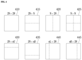
- FIG. 4 is a diagram showing the forms of a prediction unit (PU) that may be included in a CU.
- PU prediction unit
- a CU that is no longer partitioned, from among CUs partitioned from the LCU, may be partitioned into at least one PU. Such a process may also refer to partitioning.
- a prediction unit may be a basic unit of a prediction.
- the PU may be encoded and decoded in any one of a skip mode, inter-prediction mode, and intra-prediction mode.
- the PU may be partitioned in various forms depending on each mode.
- a 2N ⁇ 2N mode 410 having the same size as a CU may be supported without a partition within the CU.
- 8 partitioned forms, for example, the 2N ⁇ 2N mode 410, a 2N ⁇ 2N mode 415, an N ⁇ 2N mode 420, an N ⁇ N mode 425, a 2N ⁇ nU mode 430, a 2N ⁇ nD mode 435, an nL ⁇ 2N mode 440, and an nR ⁇ 2N mode 445 may be supported within a CU.
- FIG. 5 is a diagram showing forms of a transform unit (TU) that may be included in a CU.
- TU transform unit
- a transform unit may be a basic unit used for a transformation, a quantization, a reverse transform, and a inverse quantization process within a CU.
- the TU may have a rectangular or square form.
- the TU may be dependently determined by a size and/or a form of a CU.
- a CU that is no longer partitioned, from among CUs partitioned from the LCU, may be partitioned into one or more TUs.
- the partition structure of the TU may be a quad-tree structure.
- a single CU 510 may be partitioned once or more depending on a quad-tree structure, so that the CU 510 is formed of TUs having various sizes.
- the single CU 510 may be partitioned into at least one TU based in a number of horizontal lines and/or vertical lines that partition the CU.
- the CU may be partitioned into TUs that are symmetrical to each other, or may be partitioned into TUs that are asymmetrical to each other.
- information of size and form of the TU may be signaled, or may be derived from information of size and form of the CU.
- a residual block may be transformed by using one of predetermined methods.
- the predetermined methods may include a discrete cosine transform (DCT), a discrete sine transform (DST), or a Karhunen-Loève transform (KLT).
- DCT discrete cosine transform
- DST discrete sine transform
- KLT Karhunen-Loève transform
- the method may be determined by using at least one of inter-prediction mode information of the prediction unit, intra-prediction mode information of the prediction unit, or a size and form of the transform block.
- information indicating the method may be signaled in some cases.
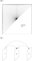
- FIG. 6 is a diagram showing an example of showing an intra-prediction mode.
- a number of intra-prediction modes may vary according to a size of a prediction unit (PU), or may be fixed to N numbers regardless of the size of the prediction unit (PU).
- the N numbers may include 35, and 67, or may be a positive integer more than 1.
- a predetermined intra-prediction mode of an encoder/decoder may include two non-angular modes and 65 angular modes, as shown in FIG. 6 .
- the two non-angular modes may include a DC mode and a planar mode.
- the number of intra-prediction modes may differ according to a type of color component.
- the number of intra-prediction modes may be varied depending on whether the color component is a luma signal or a chroma signal.
- the PU may have a square form having an NxN or a 2Nx2N size.
- the NxN size may include 4x4, 8x8, 16x16, 32x32, 64x64, 128x128, etc.
- the PU may have an MxN size.
- M and N may be a positive integer more than 2, and M and N may be different numbers.
- a unit of PU may be a size of at least one of CU, PU, and TU.
- Intra encoding and/or decoding may be performed by using a sample value included in a neighboring reconstructed unit or a coding parameter.
- a prediction block may be generated by applying a reference sample filter to a reference pixel through using at least one of sizes of encoding/decoding target blocks.
- Types of the reference filter applied to the reference pixel may differ.
- the reference filter may differ according to the intra-prediction mode of an encoding/decoding target block, a size/form of encoding/decoding target block, or a position of the reference pixel.
- “Types of the reference filter may differ” may refer to a filter coefficient of the reference filter, a number of filter taps, and filter intensity, or a number of filtering process may be differed.
- an intra-prediction mode of a current prediction unit may be predicted by an intra-prediction mode of a neighboring prediction unit that is adjacent to the current prediction unit.
- the intra-prediction mode of the current prediction unit is predicted by using intra-prediction mode information of the neighboring prediction unit, and the both of the modes are identical, information that both of modes are identical may be transmitted by using a predetermined flag.
- all prediction mode information within encoding/decoding target block may be encoded by entropy encoding.
- FIG. 7 is a diagram showing an example of an inter-prediction process.
- a rectangle of FIG. 7 may refer to an image (or picture).
- arrows of FIG. 7 may indicate a prediction direction.
- the image may be encoded and/or decoded according to the arrow directions.
- Each image may be classified into an I-picture (Intra picture), a P-picture (Uni-predictive Picture), and a B-picture (Bi-predictive Picture), etc. according to an encoding type.
- Each picture may be encoded and decoded according to an encoding type of each picture.
- the target image When an encoding target image is an I-picture, the target image itself may be intra-encoded while inter prediction is performed.
- the target image When an encoding target image is a P-picture, the target image may be encoded by inter prediction using a reference image in a forward direction, or motion compensation.
- the target image When an encoding target image is a B-picture, the target image may be encoded by inter prediction using reference pictures in a forward direction and in a reverse direction, or motion compensation.
- the target image may be encoded by inter prediction using a reference image in forward direction or in a reverse direction.
- the encoder may perform inter prediction or the motion compensation, and the decoder may perform motion compensation in response to the encoder. Images of a P-picture and B-picture that are encoded and/or decoded by using a reference image are used for inter prediction.
- Inter prediction or motion compensation may be performed by using a reference image and motion information.
- inter prediction may use the skip mode described above.
- the reference picture may be at least one of a previous picture of a current picture or a subsequent picture of the current picture.
- a block of the current picture based on the reference picture may be predicted.
- an area within the reference picture may be specified by using a reference picture index refIdx indicating the reference picture and a motion vector that will be described later.
- a reference block that corresponds to the current block within the reference picture may be selected.
- a prediction block of the current block may be generated by using the selected reference block.
- the current block may be a current encoding or decoding target block among blocks of the current picture.
- Motion information may be derived from an inter-prediction process of the encoding apparatus 100 and the decoding apparatus 200.
- the derived motion information may be used for inter prediction.
- the encoding apparatus 100 and the decoding apparatus 200 may improve efficiency of encoding and/or decoding by using motion information of a reconstructed neighboring block and/or motion information of a collocated block (col block).
- the collocated block may be a block that spatially corresponds to an encoding/decoding target block within a reconstructed collocated picture (col picture).
- the reconstructed neighboring block may be a block within the current picture and a reconstructed block through encoding and/or decoding.
- the reconstructed block may be a block adjacent to the encoding/decoding target block and/or a block positioned at an outer corner of the encoding/decoding target block.
- the block positioned at the outer corner of the encoding/decoding target block may be a block that is adjacent in a vertical direction, and the block adjacent in a vertical direction is adjacent to the encoding/decoding target block in a horizontal direction.
- the block positioned at the outer corner of the encoding/decoding target block may be a block that is adjacent in a horizontal direction, and the block adjacent in a horizontal direction is adjacent to the encoding/decoding target block in a vertical direction.
- Each of the encoding apparatus 100 and the decoding apparatus 200 may determine a predetermined relative position based on a block that is present at a position spatially corresponding to the current block within the collocated picture.
- the predetermined relative position may be positioned at an inside and/or outside of the block that is present at the position spatially corresponding to the current block.
- the encoding apparatus 100 and the decoding apparatus 200 may derive the collocated block based on the determined relative position.
- the collocated picture may be at least one picture among reference pictures included in a reference picture list.
- a method of deriving the motion information may vary according to a prediction mode of the encoding/decoding target block.
- the prediction mode applied for inter prediction may include an advanced motion vector predictor (AMVP) mode, a merge mode, and the like.
- AMVP advanced motion vector predictor
- the merge mode may refer to a motion merge mode.
- the encoding apparatus 100 and the decoding apparatus 200 may generate a prediction motion vector candidate list by using a motion vector of the restored neighboring block and/or a motion vector of the collocated block.
- the motion vector of the restored neighboring block and/or the motion vector of the collocated block may be used as a prediction motion vector candidate.
- the motion vector of the collocated block may refer to a temporal motion vector candidate
- the motion vector of the restored neighboring block may refer to a spatial motion vector candidate.
- the encoding apparatus 100 may generate a bitstream, and the bitstream may include a motion vector candidate index.
- the encoding apparatus 100 may entropy encode the motion vector candidate index to generate the bit stream.
- the motion vector candidate index may indicate an optimal prediction motion vector selected among the prediction motion vector candidates included in the motion vector candidate list.
- the motion vector candidate index may be transmitted from the encoding apparatus 100 to the decoding apparatus 200 through the bitstream.
- the decoding apparatus 200 may entropy decode the motion vector candidate index through the bit stream, and select the motion vector candidate of the decoding target block among the motion vector candidates included in the motion vector candidate list by using the entropy decoded motion vector candidate index.
- the encoding apparatus 100 may calculate a motion vector difference (MVD) between the motion vector of the encoding target block and the motion vector candidate, and may entropy encode the motion vector difference (MVD).
- the bitstream may include the entropy encoded MVD.
- the MVD is transmitted to the decoding apparatus 200 through the bitstream.
- the decoding apparatus 200 may entropy decode the MVD from the bitstream.
- the decoding apparatus 200 may derive the motion vector of the decoding target block through a sum of the decoded MVD and the motion vector candidate.
- the bitstream may include a reference picture index indicating the reference picture.
- the reference picture index may be entropy encoded and transmitted from the encoding apparatus 100 to the decoding apparatus 200 through the bitstream.
- the decoding apparatus 200 may predict the motion vector of the current block by using the motion information of the neighboring block, and may derive the motion vector of the decoding target block by using the predicted motion vector and a residual value of the predicted the motion vector.
- the decoding apparatus 200 may generate the prediction block of the decoding target block based on the derived motion vector and the reference picture index information.
- a merge mode may be used.
- the merge mode may refer to a motion merging of a plurality of blocks.
- the merge mode may also refer to applying motion information of a single block to another block.
- the encoding apparatus 100 and the decoding apparatus 200 may generate a merge candidate list by using the motion information of the restored neighboring block and/or the motion information of the collocated block.
- the motion information may include at least one of 1) the motion vector, the reference picture index, and 3) an inter-prediction indicator.
- the prediction indicator may indicate a uni-direction (LO prediction, L1 prediction), or a bi-direction.
- the merge mode may be applied in a unit of a coding unit or a prediction unit (PU).
- the encoding apparatus 100 may generate a bitstream by entropy encoding predetermined information, and transmit the bitstream to the decoding apparatus 200.
- the bitstream may include the predetermined information.
- the predetermined information may include 1) a merge flag representing whether the merge mode is used for each block partition, 2) a merge index including information to which block among the neighboring blocks adjacent to encoding target block is merged.
- neighboring blocks adjacent to encoding target block may include a left adjacent block of the current block, an upper adjacent block of the encoding target block, a temporally adjacent block of the encoding target block, and the like.
- the merge candidate list may represent a list in which the motion information is stored.
- the merge candidate list may be generated before performing the merge mode.
- the motion information stored in the merge candidate list may be at least one of motion information of the neighboring block adjacent to the encoding/decoding target block, or motion information of the collocated block corresponding to the encoding/decoding target block in the reference picture, motion information newly generated by combining the motion information that is present in the merge motion candidate list in advance, and a zero merge candidate.
- the motion information of the neighboring block adjacent to the encoding/decoding target block may refer to a spatial merge candidate
- the motion information of the collocated block corresponding to the encoding/decoding target block in the reference picture may refer to a temporal merge candidate.
- the skip mode applies the motion information of the neighboring block to the encoding/decoding target block.
- the skip mode may be one of other modes used in inter prediction.
- the encoding apparatus 100 may generate a bitstream by entropy encoding information of the neighboring block that may be used for the encoding target block, and transmit the bit stream to the decoding apparatus 200.
- the encoding apparatus 100 may not transmit other information such as syntax information to the decoding apparatus 200.
- the syntax information may include at least one of residual information of the motion vector, an encoding block flag, and a transform coefficient level.
- the intra-prediction mode is defined as an IPM.
- a secondary IPM SIPM: Secondary IPM
- SMPM Secondary MPM
- FIG. 8 is a flow chart explaining an encoding method of an intra-prediction mode according to an embodiment of the present invention.
- the encoding method may construct a first candidate mode set.
- the fist candidate mode set may include M (M is an integer equal to or greater than 1) candidate modes.
- the encoding method may perform the construction of the first candidate mode set based on an available intra-prediction mode of an upper and/or a left block adjacent to a current block.
- step S802 the encoding method may determine whether or not an intra-prediction mode of the current block is included in the first candidate mode set.
- step S806 when the intra-prediction mode of the current block is determined to be included in the first candidate mode set in step S802, the encoding method encodes the intra-prediction mode of the current block.
- the encoding method may encode information on the first determination result indicating that the intra-prediction mode of the current block is included in the first candidate mode set, and first indication information for indicating the same candidate mode as the intra-prediction mode of the current block among the M candidate modes included in the first candidate mode set.
- the first candidate mode set including the M candidate modes may correspond to an MPM candidate mode set that will be described later.
- the information on the first determination result and the first indication information may respectively correspond to an MPM flag and an MPM index that will be described later.
- the encoding method may move to step S803.
- the encoding method may construct a second candidate mode set including N (N is an integer equal to or greater than 1) candidate modes.
- the encoding method may perform the constuction of the second candidate mode set based on at least one reference prediction mode that is selected from the candidate modes included in the first candidate mode set.
- step S804 the encoding method may determine whether or not the intra-prediction mode of the current block is included in the second candidate mode set.
- the encoding method may encode information on the second determination result indicating that the intra-prediction mode of the current block is included in the second candidate mode set and second indication information for indicating the same candidate mode as the intra-prediction mode of the current block among the N candidate modes included in the second candidate mode set.
- the encoding method may encode the information on the first determination result together.
- the second candidate mode set including the N candidate modes may correspond to a second IPM candidate (candidate mode set) that will be described later.
- the information on the second determination result and the second indication information may respectively correspond to a second MPM flag (secondary MPM flag) and a second MPM index (secondary MPM index) that will be described later.
- the encoding method may move to step S805.
- the encoding method may construct a remaining candidate mode set including remaining modes that are not included in both the first and second candidate mode sets.
- the encoding method may encode information indicating that the intra-prediction mode of the current block is not included in both the first and second candidate mode sets, and third indication information indicating the same candidate mode as the intra-prediction mode of the current block among the intra prediction modes included in the remaining candidate mode set.
- the information indicating that the intra-prediction mode of the current block is not included in both the first and second candidate mode sets may be encoded by using the information on the first determination result and the information on the second determination result.
- the third indication information may correspond to an IPM index (rem_intra_luma_pred_mode) that will be described later.
- the encoding method may perform at least one additional decision step besides the steps S802 and/or S804.
- the encoding method may perform the additional decision step in an arbitrary order between the steps S801 to S806.
- the encoding method may perform the additional decision step based on at least one of the IPM of the current block, IPM(s) of neighboring block(s), a sample value of the current block, sample value(s) of the neighboring block(s), statistics of the IPMs of neighboring blocks such as distribution, an average value, a median value, a distribution value, a norm value, etc., a variation amount of the sample value of the current block and/or the neighboring blocks, IPM value(s) included in the first candidate mode set, and IPM value (s) included in the second candidate mode set.
- the encoding method may determine whether or not the IPM of the current block is included in an n-th candidate mode set in the additional decision step when 3 or more candidate mode sets are provided.
- the encoding method shown in FIG. 8 may include construct the n-th candidate mode set.
- n is an integer equal to or greater than 3.
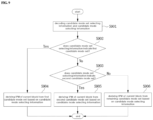
- FIG. 9 is a flow chart explaining a decoding method of an intra-prediction mode according to an embodiment of the present invention.
- the decoding method may decode candidate mode set selecting information and candidate mode selecting information.
- the candidate mode set selecting information may include first candidate mode set selecting information and/or second candidate mode set selecting information.
- the candidate mode set selecting information may correspond to the information on the first determination result and/or the information on the second determination result explained with reference to FIG. 8 .
- the candidate mode set selecting information may be decoded from a single syntax element or from multiple syntax elements. Descriptions of the first candidate mode set and the second candidate mode set may be the same as described with reference to FIG. 8 .
- the candidate mode selecting information may be information for selecting one mode among the candidate modes included in the candidate mode set.
- the candidate mode selecting information may correspond to the first, second, and/or third indication information explained with reference to FIG. 8 .
- the candidate mode selecting information may be an index indicating one candidate mode among the candidate modes included in the candidate mode set. Alternatively, the candidate mode selecting information may be information directly indicating an intra-prediction mode of a current block.
- the decoding method may determine whether or not the candidate mode set selecting information indicates the first candidate mode set.
- the candidate mode set selecting information indicates the first candidate mode set (YES)
- the first candidate mode set may be used for decoding the intra-prediction mode of the current block.
- the decoding method may derive the intra-prediction mode of the current block from the first candidate mode set based on the candidate mode selecting information.
- step S903 when the candidate mode set selecting information does not indicate the first candidate mode set (NO) in step S902, the decoding method may determine whether or not the candidate mode set selecting information indicates the second candidate mode set.
- the candidate mode set selecting information indicates the second candidate mode set (YES)
- the second candidate mode set may be used for decoding the intra-prediction mode of the current block.
- step S905 when the candidate mode set selecting information indicates the second candidate mode set, the decoding method may derive the intra-prediction mode of the current block from the second candidate mode set based on the candidate mode selecting information
- a remaining candidate mode set that is not included in both the first and second candidate mode sets may be used for decoding the intra-prediction mode of the current block.
- step S906 when candidate mode set selecting information does not indicate the second candidate mode set (NO) in step S903, the decoding method may derive the intra-prediction mode of the current block from the remaining candidate mode set based on the candidate mode selecting information.
- the decoding method may perform at least one additional decision step besides the steps S902 and/or S903.
- the decoding method may perform the additional decision step in an arbitrary order between the steps S901 to S904 or between the steps S905 or S906.
- the decoding method may perform the additional decision step based on at least one of the IPM of the current block, IPM(s) of neighboring block(s), a sample value of the current block, sample value(s) of the neighboring block(s), statistics of the IPMs of neighboring blocks such as distribution, an average value, a median value, a distribution value, a norm value, etc., a variation amount of the sample value of the current block and/or the neighboring blocks, IPM value(s) included in the first candidate mode set, and IPM value (s) included in the second candidate mode set.
- the decoding method may determine whether or not the IPM of the current block is included in an n-th candidate mode set in the additional decision step when 3 or more candidate mode sets are provided.
- the decoding method shown in FIG. 9 may include constructing the n-th candidate mode set.
- n is an integer equal to or greater than 3.
- the encoding/decoding method of the intra-prediction mode may be performed by using at least one of a method based on an MPM that will be described later, a method based on a secondary IPM (SIPM: Secondary IPM), and a method based on a remaining intra-prediction mode except for the MPM and/or the SIPM.
- SIPM Secondary IPM
- a third or more MPM candidate mode set may be used by considering a total number of predefined intra-prediction modes in the encoder/decoder, a range of an intra-prediction modes which can be used by an encoding/decoding target block, etc.
- the two non-angular modes may be a planar mode and a DC mode, and IPM indexes thereof may be set to 0 and 1, respectively.
- the 33 angular modes are as shown in FIG. 10 , IPM indexes thereof may be set to 2-34, respectively.
- an encoding method based on MPM(Most probable mode) derived from an neighboring intra-prediction block that is previously encoded/decoded may be used first.
- MPM[0] or MPM[1] may be same as Planar, DC and Vertical. Therefore, after determining whether to duplicate, another IPM may be assigned to MPM[2] according to a predetermined order (Planar -> DC ->Vertical).)
- indexes of the MPM candidates may be set as follows.
- MPM[0] Planar
- MPM[1] DC
- MPM[2] Vertical.
- indexes of the MPM candidates may be set as follows.
- MPM[0] Left_IPM
- MPM[1] Left_IPM-1
- MPM[2] Left_IPM+1.
- the MPM[2] may be assigned to an arbitrary intra-prediction mode different an intra prediction mode obtained from a neighboring block.
- At least one entropy encoding method among various entropy encoding methods may be used for encoding the corresponding information.
- IPM information including 35 intra-prediction modes by using fixed length coding (FLC)
- FLC fixed length coding
- up to 6 bits are required to binarize the IPM.
- minimum 3 bits or maximum 6 bits are encoded by encoding based on an MPM that uses an IPM correlation of neighboring blocks.
- M may be equal to or less than T.
- M is set to 3
- the flag and index information described above may use at least one of the following entropy encoding methods. After being binarized, the flag and index information may be finally encoded in CABAC(ae(v)).
- a decoder may construct M (for example, 3, 4, 5, 6, etc.) MPM candidate modes by obtaining neighboring IPM values similarly as the encoder does.
- the decoder may obtain an IPM value necessary for current decoding among the MPM candidate modes by using the MPM index.
- the decoder may obtain the IPM value necessary for current decoding among the MPM candidate modes by using the IPM index.
- an IPM index value has a value range from 0 ⁇ 31.
- the IPM index value needs to be revised since the IPM index value is not an actual IPM value of a current decoding unit. For example, when 3 MPM candidate modes actually have angular modes 3, 25, and 28 and the IPM of the current decoding block has a mode 17, the IPM index (0 ⁇ 31) may be constructed as the following table that does not include the 3 MPM candidate modes, and the encoder may transmit by entropy encoding the IPM index that corresponds to mode 16.
- the decoder may construct a revised IPM table (Revised (Rev.) IPM Table) in which the actual IPM value that matches to the IPM index is reflected. Therefore, the decoder may derive the IPM value (17) of the currently decoded intra-prediction block by using the table 1.
- the decoder may not construct the table when decoding, but obtain the IPM index value (16) and sorting corresponding MPM candidate values (3, 25, and 28) in ascending order, and obtain the IPM value of the current block by increasing by 1 when the current decoded IPM index value is greater than the MPM candidate value.
- An encoder may encode by using a secondary MPM by generating a secondary intra-prediction candidate mode list including N candidate modes when an intra-prediction mode of a current encoding intra block is not identical to any one of M candidate modes of an MPM.
- the generated N secondary IPM candidate modes include another prediction mode different from M MPM candidate modes.
- the encoder and decoder may have same number of generated N secondary IPM candidate modes.
- the number N may be an arbitrary positive integer and may be set to be equal to or smaller than a total number of the intra-prediction modes-M.
- the number of N secondary IPM candidate modes may be 4.
- the current encoding intra-prediction mode may be expressed as 4 bits. (MPM flag(1 bit, "0") + Secondary MPM flag (1 bit, "1") + SMPM index(2 bits)).
- the number of N secondary IPM candidate modes may be 16.
- the intra-prediction mode of the current encoding intra-prediction mode is identiccal to one of the secondary candidate modes, and the current encoding intra-prediction mode is binarized by FLC codeword, the current encoding intra-prediction mode may be expressed as 6 bits. (MPM flag(1 bit, "0") + Secondary MPM flag(1 bit, "1") + SMPM index(4 bit)).
- the number of candidate modes and which candidate modes to be included in the secondary IPM candidate modes may be determined according to various encoding parameters (for example, pre-defined intra-prediction related syntax, encoding parameter, size of current encoding unit, prediction unit and transform unit, information whether or not the encoding unit is partitioned, M MPM candidate modes and an intra-prediction mode of neighboring block that is not included in MPM).
- encoding parameters for example, pre-defined intra-prediction related syntax, encoding parameter, size of current encoding unit, prediction unit and transform unit, information whether or not the encoding unit is partitioned, M MPM candidate modes and an intra-prediction mode of neighboring block that is not included in MPM).
- the number of the secondary IPM candidate modes and whether or not the secondary IPM candidate mode is used may be entropy encoded/decoded in at least one of a video parameter set, a sequence parameter set, a picture parameter set, an adaptation parameter set, a slice header, a coding unit, a prediction unit, and a transform unit, or may be implicitly set in the encoder/decoder according to the same method.
- entropy encoding/decoding the at least one of the above information at least one of the following binarization methods may be used:
- the above method is not limited to using the secondary IPM candidate modes besides the MPM, and flag information and intra-prediction mode information may be encoded/decoded according to the above method by forming a third or more IPM candidate mode group.
- the secondary IPM candidate modes may be constructed according to various methods that will be described below.
- the encoder may determine an arbitrary secondary IPM candidate mode based on the following various methods.
- the decoder may derive the secondary IPM candidate modes according to the predefined rule as the encoder does.
- the secondary IPM candidate modes When the number of the secondary IPM candidate modes is N, within the allowed number, intra-prediction modes other than the existing MPM candidate modes may be included in the secondary IPM candidate modes.
- the secondary IPM candidate modes may be obtained by sub-sampling N candidate modes from the entire intra-prediction modes except for the MPM candidate modes.
- corresponding index values from 0 to N-1 which are not the unique intra-prediction mode values may be encoded.
- intra-prediction modes of a planar mode, DC mode, vertical mode, horizontal mode, diagonal angular mode may be included in the secondary IPM candidate modes since they have a high probability to be selected when a current block is homogeneous or an edge component of the current block for the diagonal angle is strong.
- intra-prediction indexes for vertical, horizontal, diagonal angular modes may correspond to 26, 10, 18, and 34, respectively.
- intra-prediction indexes for vertical, horizontal, diagonal angular modes may correspond to 50, 18, 34, and 66, respectively.
- intra-prediction indexes for a planar mode and DC mode may correspond to 0, and 1, respectively in common.
- the secondary IPM candidate modes may be constructed by using neighboring modes of the corresponding angular modes.
- the secondary IPM candidate modes may be constructed including up to N candidate modes such as K-1, K+1, K-2, K+2,
- the secondary IPM candidate modes may be constructed including L-1, L+1, L-2, L+2... and A-1, A+1, A-2, A+2, ....
- the secondary IPM candidate modes may be constructed including up to N candidate modes that are modes corresponding to a maximum value (Max), a minimum value (Min), an average value (Avg), a median value (Median) of the two angular modes and/or neighboring modes of the above derived modes such as Max -1, Max +1, Max -2, Max +2... or Min -1, Min+1, Min -2, Min +2, ... or Avg -1, Avg +1, Avg -2, Avg +2, ....
- the secondary IPM candidate modes may be constructed including neighboring modes of each angular mode or intra-prediction modes corresponding to a maximum value, a minimum value, an average value, a median value of the angular modes.
- orders constructing the secondary IPM candidate modes may be made freely; however, the encoder/decoder may follow the same order, and the number of the secondary IPM candidate modes cannot exceed N.
- intra-prediction modes constructed including values calculated by adding/subtracting (for example, Min-1,Min+1, Max+1, Max+2, etc.) may be replaced to another mode when the calculated values exceed an intra-prediction mode index range.
- Min-1,Min+1, Max+1, Max+2, etc. may be replaced to another mode when the calculated values exceed an intra-prediction mode index range.
- the secondary IPM candidate modes may include up to N candidate modes according to intra-prediction modes that have high occurrence frequency by deriving statistics of actual intra prediction modes encoded in a previously encoded picture or slice.
- the secondary IPM candidate modes may be derived by sub-sampling up to N candidate modes from the intra-prediction modes except for the intra-prediction modes included in the MPM candidate modes according to MPM construction information (for example, information on intra prediction mode included in MPM(angular mode), information about whether or not an identical intra-prediction mode occurs, distribution of intra-prediction mode indexes included in the MPM, error between a prediction block according to an angle and a reconstructed neighboring reference sample , etc.)
- MPM construction information for example, information on intra prediction mode included in MPM(angular mode), information about whether or not an identical intra-prediction mode occurs, distribution of intra-prediction mode indexes included in the MPM, error between a prediction block according to an angle and a reconstructed neighboring reference sample , etc.
- 6 MPM modes and 16 secondary IPM candidate modes may be constructed according to the following criteria.
- distribution of intra-prediction modes of the MPM within the entire intra-prediction modes may be as shown in FIG. 12 .
- L and A may be obtained from intra-prediction modes that have the highest occurrence frequency in a left block and an upper block based on a current block and are already encoded.
- Max and Min represent a maximum value and a minimum value of L and A as described above.
- the left-most column of FIG. 12 corresponds to values indicating intra-prediction modes.
- Angular modes (2 ⁇ 66) among the intra-prediction modes are represented in a light gray color
- non-angular modes O (planar mode) and 1 (DC mode) are represented in a white color.
- the second column to the last column of FIG. 12 correspond to various cases (Case 1 ⁇ Case 6) that select the MPM candidate mode based on L and A. According to each column, the selected MPM candidate mode is represented in a light gray color.
- 6 MPM candidate modes may include C, planar, C+1, C-1, C+2, and DC modes.
- 6 MPM candidate modes may include planar, DC, vertical (50), horizontal (18), 2, and 34 modes.
- 6 MPM candidate modes may include L, A, Planar, Max-1,Max+1, and Max+2 modes.
- 6 MPM candidate modes may include L, A, Planar, DC, Max+1, and Min-1 modes.
- 6 MPM candidate modes may include L, A, vertical (50), horizontal (18), 2, and 34 modes.
- 6 MPM candidate modes may include L, A, DC, Max-1, Max+1, and Max+2 modes.
- the sub-sampling for constructing the secondary IPM candidate modes may be performed using at least intra-prediction mode included in the MPM candidate modes as a reference prediction mode.
- the reference prediction mode may be a predetermined positional angular mode among the intra-prediction mode included in the MPM. Alternatively, it may be one or more angular modes among the intra-prediction mode included in the MPM. At least one of a minimum value, a maximum value, an average value, a median value of angular modes or an intra-prediction mode derived from neighboring prediction blocks (L or A) may be set to the reference prediction mode.
- the sub-sampling may be performed by setting at least one of the intra-prediction modes except for the MPM candidate modes as the reference prediction mode. In one embodiment, a minimum value among the remaining intra-prediction modes may be set as the reference prediction mode.
- FIG. 13 is a diagram explaining various embodiments constructing the secondary IPM candidate modes based on the construction of the MPM candidate modes according to the first case of FIG. 12 .
- 0 ⁇ 66 are indexes of 67 intra-prediction modes.
- 0 and 1 may represent a planar mode and a DC mode.
- the secondary IPM candidate modes are set to 16 candidate modes.
- the MPM candidate modes are represented in a light gray color.
- modes that are selected as the secondary IPM candidate modes are represented in a dark gray color.
- an intra-prediction mode derived from the left and upper part has a single angular mode (C), and in order to construct the MPM candidate modes having M modes (6 modes in the present embodiment), planar, C+1, C-1, C+2, DC modes are added to the MPM candidate modes.
- a reference prediction mode of the sub-sampling to construct N secondary IPM candidate modes may be the angular mode C.
- the N secondary IPM candidate modes may be sub-sampled according to following various embodiments based on C-1 and C+2.
- the same number (N/2) of intra-prediction modes that are smaller than C-1 and intra-prediction modes that are greater than C+1 may be selected, or may be selected in different numbers.
- an index interval may be set to 2 as shown in FIGS. 13(1) and 13(2).
- the index interval may be set to 1 as shown in FIG. 13(3) .
- the secondary IPM candidate modes may be constructed with a bigger interval.
- a part of the secondary IPM candidate modes may be constructed by using the above method, and a part of the remaining secondary IPM candidate modes may be constructed with intra-prediction modes adjacent to a planar mode and a DC mode.
- FIGS. 13(4) and 13(5) are examples in which 4 intra-prediction modes that are adjacent to the planar and DC modes and the rest 12 intra-prediction modes that are adjacent to the angular modes are used to construct the secondary IPM candidate modes.
- index intervals of intra prediction modes neighboring the planar mode and the DC mode may be set to 1, 2, or more as described above.
- the N secondary IPM candidate modes may be constructed with prediction mode values that are different from each other. When prediction mode values are saturated, the corresponding value may be replaced with another value. For example, when an intra-prediction mode having an arbitrary value greater than C+2 in FIG. 13(1) is obtained as the secondary IPM candidate mode and the arbitrary value exceeds 66, then the arbitrary value may be changed in another intra-prediction mode having a smaller value than 66, or may be changed in an intra-prediction mode with a value bigger than 2.
- the intra-prediction mode when an intra-prediction mode having an arbitrary value smaller than C-1 is obtained as the secondary IPM candidate mode and the arbitrary value is smaller than 2, the intra-prediction mode may be changed to an intra-prediction mode with a value of 2 or bigger than 2, or with a value smaller than 66.
- N secondary IPM candidate modes may be constructed by using the method described above.
- the N secondary IPM candidate modes may be indexed as 0, 1, 2, ..., N-1, and the index value of the N secondary IPM candidate modes indicating the same intra prediction mode value as the current intra-prediction mode may be transmitted.
- the secondary IPM candidate mode that is smaller than C-1 or greater than C+2 may be indexed in turn from 0 to N-1.
- the N secondary IPM candidate modes may be indexed from 0 to N-1 according to an ascending order or a descending order based on unique values of intra-prediction modes according to an angle.
- the secondary IPM candidate modes selected in neighbors of planar/DC modes are indexed first and the remaining secondary IPM candidate modes may be indexed in an arbitrary order.
- the secondary IPM candidate modes may be indexed from 0 to N-1 according to encoding parameter information or a method that is identically derived in the encoder/decoder.
- FIG. 14 is a diagram explaining an example of constructing the N secondary IPM candidate modes based on Case 2 or Case 5 of FIG. 12 .
- modes represented in a light gray color correspond to modes that are determined as MPM candidate modes
- modes represented in a dark gray color correspond to the secondary IPM candidate modes.
- intra-prediction modes derived from a neighbor are planar and DC modes.
- vertical (50), horizontal (18), and diagonal (2, and 34) modes are included in the MPM candidate modes based on 67 intra-prediction mode indexes.
- intra-prediction mode values that are adjacent to the pre-selected MPM intra-prediction modes may be selected.
- the 16 secondary IPM candidate modes may include intra-prediction modes having the same numbers or having different numbers around the MPM candidate modes, or may be sub-sampled by applying an arbitrary index interval (1 or 2).
- the sub-sampling method for constructing the secondary IPM candidate modes may be performed by using various methods as in the Case 1 described above. In this case, the entire prediction modes shall be different from each other and the maximum number shall not exceed the number N.
- the N secondary MPM candidate modes may be indexed as 0, 1, 2, ..., N-1 as described above.
- FIG. 15 is a diagram explaining an example of constructing the N secondary IPM candidate modes based on Case 4 of FIG. 12 .
- modes represented in a light gray color correspond to modes that are determined as MPM candidate modes
- modes represented in a dark gray color correspond to the secondary IPM candidate modes.
- neighboring intra-prediction modes are angular modes that are different from each other, and thus the N secondary IPM candidate modes may be constructed with neighboring intra-prediction modes that are adjacent to the corresponding angular modes.
- intra-prediction modes that are adjacent to the pre-selected MPM based prediction modes may be selected.
- intra-prediction modes having the same numbers or having different numbers around angular prediction modes included in the MPM may be sub-sampled.
- the entire 16 number of the secondary IPM candidate modes may be constructed with a part using neighboring intra-prediction modes of two different intra-prediction modes, and the other part using intra-prediction modes neighboring a planar mode or a DC mode.
- the N secondary MPM candidate modes may be indexed as 0, 1, 2, ..., N-1 as described above.
- the N secondary IPM candidate modes may be sub-sampled according to distribution and features of the MPM as the above embodiments.
- the N secondary IPM candidate modes may be sub-sampled according to an arbitrary index interval by sorting the remaining intra-prediction modes, except for the MPM candidate modes, in an ascending order or in a descending order.
- the arbitrary index interval may be a positive integer equal to or bigger than 1.
- 61 intra-prediction modes when 67 intra-prediction modes are supported and 6 MPM candidate modes are included therein, 61 intra-prediction modes, except for the 6 MPM candidate modes, are sorted in an ascending order or in a descending order based on unique angular values thereof.
- the 61 sorted intra-prediction modes may respectively have indexes range from 0 to 60.
- the N secondary IPM candidate modes may be constructed according to an arbitrary index interval.
- the intra-prediction modes may be identically sorted in an encoder/decoder.
- the N secondary IPM candidate modes may be constructed with intra prediction modes having indexes 0, 2, 4, 8, 10, ....
- the intra-prediction mode index finally encoded may be indexed as 0,1, 2, ... N-1, and the corresponding information may be encoded.
- the N secondary IPM candidate modes may be constructed with intra prediction modes having indexes 0, 4, 8, 16, ....
- the intra-prediction mode index finally encoded may be indexed as 0,1, 2, ... N-1, and the corresponding information may be encoded.
- Step 2 When a current intra-prediction mode is identical to one of the secondary IPM candidate modes, then index thereof (SMPM index) may be encoded.
- IPM index may be encoded in a existing way.
- information to be transmitted may be entropy encoded/decoded in at least one of a video parameter set, a sequence parameter set, a picture parameter set, an adaptation parameter set, a slice header, a coding unit, a prediction unit, and a transform unit, or may be implicitly set in the encoder/decoder according to the same method.
- the information may be encoded by using one of the following binarization methods.
- a decoding process may be performed as follows according to a series of procedures that take place during the encoding process.
- an intra-prediction mode value may be decoded through a MPM candidate list and an LPK index.
- the secondary IPM candidate modes may be generated based on the same criteria set for the encoder/decoder and the intra-prediction mode value may be decode by decoding a SMPM index value.
- the intra-prediction mode value may be decoded through an IPM index.
- An intra-prediction mode corresponding to the decoded IPM index may be set as an intra-prediction mode of a current block.
- the intra-prediction mode of the current block may be derived by adding a predetermined value to the IPM index through a comparison between the decoded IPM index and a MPM candidate value and/or a SIPM candidate value.
- the predetermined value may be determined based on the number of MPM candidate value that is equal to or smaller than the decoded IPM index and/or the number of SIPM candidate values that is equal to or smaller than the decoded IPM index.
- the MPM candidate value and/or the SIPM candidate value may be sorted in an ascending order or in a descending order.
- the MPM candidate value and/or the SIPM candidate value may be sorted in an ascending order, and the sorted values may be compared with the decoded IPM index sequentially.
- the decoded IPM index is equal to or greater than the MPM candidate value and/or the SIPM candidate value, the decoded IPM index is increased by 1.
- Such a process may be repeated as many times as the numner of an MPM candidate value and/or SIPM candidate values that are equal to or smaller than the decoded IPM index.
- the step of increasing the IPM index by 1 may be finished.
- the flag being "1" may represent that the current intra-prediction mode is identical to one of the MPM candidate modes or the secondary IPM candidate modes.
- the flag may be expressed as 1 or 0.
- one of decoding methods of an intra-prediction mode may be selectively used among an intra prediction mode decoding method based on MPM candidate (first method), an intra prediction mode decoding method based on a secondary IPM candidate (second method), and an intra prediction mode decoding method based on a remaining IPM mode (third method) by sequentially signaling the flag information.
- an identifier indicating one of the three methods may be used.
- the information may be encoded by using one of the following binarization methods:
- a SMPM index and an IPM index may be entropy encoded in FLC or in TU.
- the SMPM index may be binarized in FLC, and the IPM index may be encoded/decoded in TU.
- the SMPM index may be binarized in TU, and the IPM index may be encoded/decoded in FLC.
- the computer-readable storage medium may include a program instruction, a data file, a data structure, and the like either alone or in combination thereof.
- the program instruction recorded in the computer-readable storage medium may be any program instruction particularly designed and structured for the present invention or known to those skilled in the field of computer software.
- Examples of the computer-readable storage medium include magnetic recording media such as hard disks, floppy disks and magnetic tapes; optical data storage media such as CD-ROMs or DVD-ROMs; magneto-optical media such as floptical disks; and hardware devices, such as read-only memory (ROM), random-access memory (RAM), and flash memory, which are particularly structured to store and implement the program instruction.
- Examples of the program instruction include not only a mechanical language code formatted by a compiler but also a high level language code which may be implemented by a computer using an interpreter.
- the hardware devices may be configured to be operated by one or more software modules or vice versa to conduct the processes according to the present invention.
- the present invention may be used for encoding/decoding an image.
Landscapes
- Engineering & Computer Science (AREA)
- Multimedia (AREA)
- Signal Processing (AREA)
- Compression Or Coding Systems Of Tv Signals (AREA)
- Compression, Expansion, Code Conversion, And Decoders (AREA)
Applications Claiming Priority (4)
| Application Number | Priority Date | Filing Date | Title |
|---|---|---|---|
| KR20150162747 | 2015-11-19 | ||
| KR1020160089419A KR20170058837A (ko) | 2015-11-19 | 2016-07-14 | 화면내 예측모드 부호화/복호화 방법 및 장치 |
| PCT/KR2016/013363 WO2017086746A1 (fr) | 2015-11-19 | 2016-11-18 | Procédé et appareil d'encodage/décodage d'un mode de prédiction intra-écran. |
| EP16866698.0A EP3379829A4 (fr) | 2015-11-19 | 2016-11-18 | Procédé et appareil d'encodage/décodage d'un mode de prédiction intra-écran. |
Related Parent Applications (1)
| Application Number | Title | Priority Date | Filing Date |
|---|---|---|---|
| EP16866698.0A Division EP3379829A4 (fr) | 2015-11-19 | 2016-11-18 | Procédé et appareil d'encodage/décodage d'un mode de prédiction intra-écran. |
Publications (1)
| Publication Number | Publication Date |
|---|---|
| EP4192009A1 true EP4192009A1 (fr) | 2023-06-07 |
Family
ID=58719204
Family Applications (1)
| Application Number | Title | Priority Date | Filing Date |
|---|---|---|---|
| EP23153916.4A Pending EP4192009A1 (fr) | 2015-11-19 | 2016-11-18 | Procédé et appareil de codage/décodage de mode de prédiction intra |
Country Status (4)
| Country | Link |
|---|---|
| US (2) | US12069237B2 (fr) |
| EP (1) | EP4192009A1 (fr) |
| KR (4) | KR20170058871A (fr) |
| WO (1) | WO2017086746A1 (fr) |
Families Citing this family (21)
| Publication number | Priority date | Publication date | Assignee | Title |
|---|---|---|---|---|
| KR20170058871A (ko) | 2015-11-19 | 2017-05-29 | 한국전자통신연구원 | 화면내 예측 모드 부호화/복호화 방법 및 장치 |
| CN115174911A (zh) * | 2017-07-24 | 2022-10-11 | 艾锐势有限责任公司 | 帧内模式jvet编译方法 |
| US10863172B2 (en) | 2017-07-24 | 2020-12-08 | Arris Enterprises Llc | Intra mode JVET coding |
| WO2019137732A1 (fr) * | 2018-01-12 | 2019-07-18 | Telefonaktiebolaget Lm Ericsson (Publ) | Codage en mode intra utilisant des statistiques d'utilisation de mode pour générer une liste mpm |
| CN116866566A (zh) * | 2018-03-21 | 2023-10-10 | Lx 半导体科技有限公司 | 图像编码/解码方法、存储介质以及图像数据的传输方法 |
| WO2020003270A1 (fr) | 2018-06-29 | 2020-01-02 | Beijing Bytedance Network Technology Co., Ltd. | Nombre de candidats de mouvement dans une table de consultation à vérifier selon un mode |
| KR20210024502A (ko) | 2018-06-29 | 2021-03-05 | 베이징 바이트댄스 네트워크 테크놀로지 컴퍼니, 리미티드 | Hmvp 후보를 병합/amvp에 추가할 때의 부분/풀 프루닝 |
| KR102646649B1 (ko) | 2018-06-29 | 2024-03-13 | 베이징 바이트댄스 네트워크 테크놀로지 컴퍼니, 리미티드 | Lut에서의 모션 후보들의 검사 순서 |
| CN110662059B (zh) | 2018-06-29 | 2021-04-20 | 北京字节跳动网络技术有限公司 | 使用查找表存储先前编码的运动信息并用其编码后续块的方法和装置 |
| CN110662063B (zh) | 2018-06-29 | 2020-12-15 | 北京字节跳动网络技术有限公司 | 视频处理方法、装置和计算机可读存储介质 |
| WO2020003284A1 (fr) | 2018-06-29 | 2020-01-02 | Beijing Bytedance Network Technology Co., Ltd. | Interaction entre table de conversion et amvp |
| CN114845108A (zh) | 2018-06-29 | 2022-08-02 | 抖音视界(北京)有限公司 | 查找表的更新:fifo、约束的fifo |
| WO2020003261A1 (fr) | 2018-06-29 | 2020-01-02 | Beijing Bytedance Network Technology Co., Ltd. | Sélection à partir de multiples lut |
| CN115134599A (zh) | 2018-06-29 | 2022-09-30 | 抖音视界有限公司 | 更新查找表(lut)的条件 |
| JP7181395B2 (ja) | 2018-07-02 | 2022-11-30 | 北京字節跳動網絡技術有限公司 | イントラ予測モードを有するルックアップテーブルおよび非隣接ブロックからのイントラモード予測 |
| EP3799690B1 (fr) | 2018-07-11 | 2023-10-25 | Huawei Technologies Co., Ltd. | Signalisation en mode intra de luminance |
| TWI820211B (zh) | 2018-09-12 | 2023-11-01 | 大陸商北京字節跳動網絡技術有限公司 | 取決於總數減去k的開始檢查hmvp候選的條件 |
| WO2020143741A1 (fr) | 2019-01-10 | 2020-07-16 | Beijing Bytedance Network Technology Co., Ltd. | Invocation de mise à jour de table de consultation |
| CN113383554B (zh) | 2019-01-13 | 2022-12-16 | 北京字节跳动网络技术有限公司 | LUT和共享Merge列表之间的交互 |
| WO2020147772A1 (fr) | 2019-01-16 | 2020-07-23 | Beijing Bytedance Network Technology Co., Ltd. | Déduction de candidats de mouvement |
| WO2020192611A1 (fr) | 2019-03-22 | 2020-10-01 | Beijing Bytedance Network Technology Co., Ltd. | Interaction entre une construction de liste de fusion et d'autres outils |
Citations (2)
| Publication number | Priority date | Publication date | Assignee | Title |
|---|---|---|---|---|
| WO2012171463A1 (fr) * | 2011-06-17 | 2012-12-20 | Mediatek Inc. | Procédé et appareil de codage d'un mode de prévision interne |
| WO2014106746A1 (fr) * | 2013-01-04 | 2014-07-10 | Canon Kabushiki Kaisha | Procédé et dispositif de traitement d'informations de prédiction pour l'encodage d'une image |
Family Cites Families (36)
| Publication number | Priority date | Publication date | Assignee | Title |
|---|---|---|---|---|
| KR100584422B1 (ko) | 2003-06-04 | 2006-05-26 | 삼성전자주식회사 | 영상데이터의 압축 장치 및 방법 |
| FR2881898A1 (fr) * | 2005-02-10 | 2006-08-11 | Thomson Licensing Sa | Procede et dispositif de codage d'une image video en mode inter ou intra |
| US8392255B2 (en) | 2007-08-29 | 2013-03-05 | The Nielsen Company (Us), Llc | Content based selection and meta tagging of advertisement breaks |
| CN101641958B (zh) | 2007-09-12 | 2011-10-19 | 索尼株式会社 | 图像处理设备和图像处理方法 |
| JP5169978B2 (ja) | 2009-04-24 | 2013-03-27 | ソニー株式会社 | 画像処理装置および方法 |
| US8902978B2 (en) * | 2010-05-30 | 2014-12-02 | Lg Electronics Inc. | Enhanced intra prediction mode signaling |
| KR20120070479A (ko) | 2010-12-21 | 2012-06-29 | 한국전자통신연구원 | 화면 내 예측 방향 정보 부호화/복호화 방법 및 그 장치 |
| KR20120129726A (ko) | 2011-05-20 | 2012-11-28 | 주식회사 케이티 | 인트라 예측 모드 복호화 방법 및 복호화 장치 |
| PL3751854T3 (pl) | 2011-05-24 | 2023-08-28 | Sun Patent Trust | Sposób kodowania obrazu, urządzenie do kodowania obrazu, sposób dekodowania obrazu, urządzenie do dekodowania obrazu oraz urządzenie do kodowania/dekodowania obrazu |
| US9654785B2 (en) * | 2011-06-09 | 2017-05-16 | Qualcomm Incorporated | Enhanced intra-prediction mode signaling for video coding using neighboring mode |
| KR101876173B1 (ko) * | 2011-06-17 | 2018-07-09 | 엘지전자 주식회사 | 인트라 예측 모드 부호화/복호화 방법 및 장치 |
| US8805099B2 (en) | 2011-06-22 | 2014-08-12 | Panasonic Intellectual Property Corporation Of America | Image decoding method and image coding method |
| DK2838270T3 (da) | 2011-06-28 | 2017-01-02 | Samsung Electronics Co Ltd | Videoafkodningsfremgangsmåde ved anvendelse af intraforudsigelse |
| US9621888B2 (en) * | 2011-09-09 | 2017-04-11 | Lg Electronics Inc. | Inter prediction method and apparatus therefor |
| KR101974952B1 (ko) * | 2011-10-06 | 2019-05-07 | 인텔렉추얼디스커버리 주식회사 | 두 개의 후보 인트라 예측 모드를 이용한 화면 내 예측 모드의 부/복호화 방법 및 이러한 방법을 사용하는 장치 |
| KR102512333B1 (ko) | 2011-10-18 | 2023-03-22 | 엘지전자 주식회사 | 인트라 예측 방법 및 그 장치 |
| CN104170379B (zh) * | 2011-10-24 | 2016-01-20 | 英孚布瑞智有限私人贸易公司 | 用于图像解码的方法和装置 |
| KR102616815B1 (ko) * | 2011-12-05 | 2023-12-21 | 엘지전자 주식회사 | 인트라 예측 방법 및 장치 |
| KR101827939B1 (ko) * | 2011-12-13 | 2018-02-12 | 주식회사 스카이미디어테크 | 적응적인 인트라 예측 모드 부호화 방법 및 장치, 그리고 복호화 방법 및 장치 |
| KR20130072139A (ko) * | 2011-12-21 | 2013-07-01 | 연세대학교 산학협력단 | 적응적인 후보 예측 모드에 따른 인트라 예측 부호화 방법 및 그 장치 |
| KR102186404B1 (ko) * | 2012-02-29 | 2020-12-03 | 한국전자통신연구원 | 화면 내 예측 모드의 부호화 방법 및 복호화 방법 |
| KR20130107861A (ko) | 2012-03-23 | 2013-10-02 | 한국전자통신연구원 | 인터 레이어 인트라 예측 방법 및 장치 |
| US9159135B2 (en) | 2012-03-28 | 2015-10-13 | Intel Corporation | Systems, methods, and computer program products for low-latency warping of a depth map |
| KR20130112374A (ko) | 2012-04-04 | 2013-10-14 | 한국전자통신연구원 | 고속 인트라 예측을 위한 영상 부호화 방법 및 장치 |
| US20140064359A1 (en) * | 2012-08-31 | 2014-03-06 | Qualcomm Incorporated | Intra prediction most probable mode order improvement for scalable video coding |
| CN104904209B (zh) * | 2013-01-07 | 2018-07-24 | Lg 电子株式会社 | 视频信号处理方法 |
| GB2521606A (en) * | 2013-12-20 | 2015-07-01 | Canon Kk | Method and apparatus for transition encoding in video coding and decoding |
| CN106134201B (zh) * | 2014-05-23 | 2019-10-25 | 华为技术有限公司 | 在块预测技术中使用的预处理预测滤波的方法和装置 |
| JP6308449B2 (ja) * | 2014-06-26 | 2018-04-11 | ホアウェイ・テクノロジーズ・カンパニー・リミテッド | 高効率ビデオ符号化における演算負荷を低減するための方法および装置 |
| CN107005701A (zh) | 2014-09-23 | 2017-08-01 | 英特尔公司 | 使用减少数量的角模式来降低帧内预测复杂度及其后续改进 |
| GB2557809B (en) * | 2015-08-28 | 2021-12-01 | Kt Corp | Method and device for processing video signal |
| KR20170058871A (ko) | 2015-11-19 | 2017-05-29 | 한국전자통신연구원 | 화면내 예측 모드 부호화/복호화 방법 및 장치 |
| KR20170058837A (ko) * | 2015-11-19 | 2017-05-29 | 한국전자통신연구원 | 화면내 예측모드 부호화/복호화 방법 및 장치 |
| US10448011B2 (en) | 2016-03-18 | 2019-10-15 | Mediatek Inc. | Method and apparatus of intra prediction in image and video processing |
| US10708164B2 (en) | 2016-05-03 | 2020-07-07 | Qualcomm Incorporated | Binarizing secondary transform index |
| CA3025488A1 (fr) * | 2016-05-25 | 2017-11-30 | Arris Enterprises Llc | Prediction angulaire ponderee pour codage intra |
-
2016
- 2016-11-18 KR KR1020160154385A patent/KR20170058871A/ko active Application Filing
- 2016-11-18 EP EP23153916.4A patent/EP4192009A1/fr active Pending
- 2016-11-18 WO PCT/KR2016/013363 patent/WO2017086746A1/fr active Application Filing
-
2021
- 2021-11-08 KR KR1020210152279A patent/KR102644043B1/ko active IP Right Grant
-
2022
- 2022-08-11 US US17/886,154 patent/US12069237B2/en active Active
- 2022-09-20 KR KR1020220118490A patent/KR102618393B1/ko active IP Right Grant
-
2023
- 2023-04-05 US US18/296,344 patent/US12088785B2/en active Active
-
2024
- 2024-02-23 KR KR1020240026640A patent/KR20240028404A/ko active Application Filing
Patent Citations (2)
| Publication number | Priority date | Publication date | Assignee | Title |
|---|---|---|---|---|
| WO2012171463A1 (fr) * | 2011-06-17 | 2012-12-20 | Mediatek Inc. | Procédé et appareil de codage d'un mode de prévision interne |
| WO2014106746A1 (fr) * | 2013-01-04 | 2014-07-10 | Canon Kabushiki Kaisha | Procédé et dispositif de traitement d'informations de prédiction pour l'encodage d'une image |
Non-Patent Citations (2)
| Title |
|---|
| CHEN (QUALCOMM) J ET AL: "Algorithm description of Joint Exploration Test Model 2", no. JVET-B1001, 8 March 2016 (2016-03-08), XP030150091, Retrieved from the Internet <URL:http://phenix.int-evry.fr/jvet/doc_end_user/documents/2_San%20Diego/wg11/JVET-B1001-v1.zip JVET-B1001_V1.doc> [retrieved on 20160308] * |
| SEREGIN V ET AL: "Block shape dependent intra mode coding", 4. JVET MEETING; 15-10-2016 - 21-10-2016; CHENGDU; (THE JOINT VIDEO EXPLORATION TEAM OF ISO/IEC JTC1/SC29/WG11 AND ITU-T SG.16 ); URL: HTTP://PHENIX.INT-EVRY.FR/JVET/, no. JVET-D0114-v3, 15 October 2016 (2016-10-15), XP030150362 * |
Also Published As
| Publication number | Publication date |
|---|---|
| KR20230174747A (ko) | 2023-12-28 |
| KR20210135466A (ko) | 2021-11-15 |
| KR20220132504A (ko) | 2022-09-30 |
| KR20170058871A (ko) | 2017-05-29 |
| US20230308634A1 (en) | 2023-09-28 |
| US12088785B2 (en) | 2024-09-10 |
| US20220385887A1 (en) | 2022-12-01 |
| US12069237B2 (en) | 2024-08-20 |
| WO2017086746A1 (fr) | 2017-05-26 |
| KR102618393B1 (ko) | 2023-12-27 |
| KR20240028404A (ko) | 2024-03-05 |
| KR102644043B1 (ko) | 2024-03-06 |
Similar Documents
| Publication | Publication Date | Title |
|---|---|---|
| US12069237B2 (en) | Method and apparatus for encoding/decoding intra prediction mode | |
| US11451767B2 (en) | Method and apparatus for encoding/decoding intra prediction mode | |
| US11683475B2 (en) | Method and apparatus for image encoding/decoding | |
| KR102391524B1 (ko) | 영상 부호화/복호화 방법, 장치 및 비트스트림을 저장한 기록 매체 | |
| KR102424240B1 (ko) | 영상 부호화/복호화 방법, 장치 및 비트스트림을 저장한 기록 매체 | |
| US11438589B2 (en) | Video encoding/decoding method and apparatus, and recording medium in which bit stream is stored | |
| KR102328179B1 (ko) | 영상 부호화/복호화 방법, 장치 및 비트스트림을 저장한 기록 매체 | |
| US12101470B2 (en) | Method and apparatus for image encoding/decoding | |
| CN118214856A (zh) | 用于基于非对称子块的图像编码/解码的方法及装置 | |
| KR20170132682A (ko) | 영상 부호화/복호화 방법 및 이를 위한 기록 매체 | |
| KR102390452B1 (ko) | 영상 부호화/복호화 방법, 장치 및 비트스트림을 저장한 기록 매체 | |
| CN113228645A (zh) | 图像编码/解码方法和装置以及存储有比特流的记录介质 | |
| CN114503566A (zh) | 图像编码/解码方法和设备以及存储比特流的记录介质 | |
| KR102718160B1 (ko) | 화면내 예측 모드 부호화/복호화 방법 및 장치 | |
| US20240357109A1 (en) | Video encoding/decoding method and apparatus, and recording medium in which bit stream is stored | |
| CN113287305B (zh) | 视频编码/解码方法、装置以及在其中存储比特流的记录介质 | |
| CN113261286A (zh) | 用于推导帧内预测模式的方法和设备 |
Legal Events
| Date | Code | Title | Description |
|---|---|---|---|
| PUAI | Public reference made under article 153(3) epc to a published international application that has entered the european phase |
Free format text: ORIGINAL CODE: 0009012 |
|
| STAA | Information on the status of an ep patent application or granted ep patent |
Free format text: STATUS: THE APPLICATION HAS BEEN PUBLISHED |
|
| AC | Divisional application: reference to earlier application |
Ref document number: 3379829 Country of ref document: EP Kind code of ref document: P |
|
| AK | Designated contracting states |
Kind code of ref document: A1 Designated state(s): AL AT BE BG CH CY CZ DE DK EE ES FI FR GB GR HR HU IE IS IT LI LT LU LV MC MK MT NL NO PL PT RO RS SE SI SK SM TR |
|
| P01 | Opt-out of the competence of the unified patent court (upc) registered |
Effective date: 20230810 |
|
| STAA | Information on the status of an ep patent application or granted ep patent |
Free format text: STATUS: REQUEST FOR EXAMINATION WAS MADE |
|
| 17P | Request for examination filed |
Effective date: 20231121 |
|
| RBV | Designated contracting states (corrected) |
Designated state(s): AL AT BE BG CH CY CZ DE DK EE ES FI FR GB GR HR HU IE IS IT LI LT LU LV MC MK MT NL NO PL PT RO RS SE SI SK SM TR |