EP4191995A1 - Camera system and driving assistance system - Google Patents
Camera system and driving assistance system Download PDFInfo
- Publication number
- EP4191995A1 EP4191995A1 EP21851118.6A EP21851118A EP4191995A1 EP 4191995 A1 EP4191995 A1 EP 4191995A1 EP 21851118 A EP21851118 A EP 21851118A EP 4191995 A1 EP4191995 A1 EP 4191995A1
- Authority
- EP
- European Patent Office
- Prior art keywords
- image
- driver
- camera
- controller
- display
- Prior art date
- Legal status (The legal status is an assumption and is not a legal conclusion. Google has not performed a legal analysis and makes no representation as to the accuracy of the status listed.)
- Pending
Links
- 238000001514 detection method Methods 0.000 claims abstract description 25
- 238000000034 method Methods 0.000 claims abstract description 22
- 230000008569 process Effects 0.000 claims abstract description 21
- 230000004044 response Effects 0.000 claims abstract description 13
- 239000000203 mixture Substances 0.000 claims abstract description 5
- 230000004888 barrier function Effects 0.000 claims description 49
- 238000012544 monitoring process Methods 0.000 abstract description 15
- 230000003287 optical effect Effects 0.000 description 36
- 210000001747 pupil Anatomy 0.000 description 15
- 238000010586 diagram Methods 0.000 description 14
- 238000002834 transmittance Methods 0.000 description 11
- 238000004891 communication Methods 0.000 description 9
- 239000002131 composite material Substances 0.000 description 9
- 239000004973 liquid crystal related substance Substances 0.000 description 9
- 230000006870 function Effects 0.000 description 8
- 230000005540 biological transmission Effects 0.000 description 4
- 238000010276 construction Methods 0.000 description 2
- 210000003128 head Anatomy 0.000 description 2
- 239000004065 semiconductor Substances 0.000 description 2
- 239000011230 binding agent Substances 0.000 description 1
- 230000037237 body shape Effects 0.000 description 1
- 230000008859 change Effects 0.000 description 1
- 230000000295 complement effect Effects 0.000 description 1
- 239000011159 matrix material Substances 0.000 description 1
- 229910044991 metal oxide Inorganic materials 0.000 description 1
- 150000004706 metal oxides Chemical class 0.000 description 1
- 230000000717 retained effect Effects 0.000 description 1
- 239000007787 solid Substances 0.000 description 1
Images


Classifications
-
- B—PERFORMING OPERATIONS; TRANSPORTING
- B60—VEHICLES IN GENERAL
- B60K—ARRANGEMENT OR MOUNTING OF PROPULSION UNITS OR OF TRANSMISSIONS IN VEHICLES; ARRANGEMENT OR MOUNTING OF PLURAL DIVERSE PRIME-MOVERS IN VEHICLES; AUXILIARY DRIVES FOR VEHICLES; INSTRUMENTATION OR DASHBOARDS FOR VEHICLES; ARRANGEMENTS IN CONNECTION WITH COOLING, AIR INTAKE, GAS EXHAUST OR FUEL SUPPLY OF PROPULSION UNITS IN VEHICLES
- B60K35/00—Instruments specially adapted for vehicles; Arrangement of instruments in or on vehicles
- B60K35/10—Input arrangements, i.e. from user to vehicle, associated with vehicle functions or specially adapted therefor
-
- B—PERFORMING OPERATIONS; TRANSPORTING
- B60—VEHICLES IN GENERAL
- B60K—ARRANGEMENT OR MOUNTING OF PROPULSION UNITS OR OF TRANSMISSIONS IN VEHICLES; ARRANGEMENT OR MOUNTING OF PLURAL DIVERSE PRIME-MOVERS IN VEHICLES; AUXILIARY DRIVES FOR VEHICLES; INSTRUMENTATION OR DASHBOARDS FOR VEHICLES; ARRANGEMENTS IN CONNECTION WITH COOLING, AIR INTAKE, GAS EXHAUST OR FUEL SUPPLY OF PROPULSION UNITS IN VEHICLES
- B60K35/00—Instruments specially adapted for vehicles; Arrangement of instruments in or on vehicles
- B60K35/20—Output arrangements, i.e. from vehicle to user, associated with vehicle functions or specially adapted therefor
- B60K35/21—Output arrangements, i.e. from vehicle to user, associated with vehicle functions or specially adapted therefor using visual output, e.g. blinking lights or matrix displays
- B60K35/211—Output arrangements, i.e. from vehicle to user, associated with vehicle functions or specially adapted therefor using visual output, e.g. blinking lights or matrix displays producing three-dimensional [3D] effects, e.g. stereoscopic images
-
- B—PERFORMING OPERATIONS; TRANSPORTING
- B60—VEHICLES IN GENERAL
- B60K—ARRANGEMENT OR MOUNTING OF PROPULSION UNITS OR OF TRANSMISSIONS IN VEHICLES; ARRANGEMENT OR MOUNTING OF PLURAL DIVERSE PRIME-MOVERS IN VEHICLES; AUXILIARY DRIVES FOR VEHICLES; INSTRUMENTATION OR DASHBOARDS FOR VEHICLES; ARRANGEMENTS IN CONNECTION WITH COOLING, AIR INTAKE, GAS EXHAUST OR FUEL SUPPLY OF PROPULSION UNITS IN VEHICLES
- B60K35/00—Instruments specially adapted for vehicles; Arrangement of instruments in or on vehicles
- B60K35/20—Output arrangements, i.e. from vehicle to user, associated with vehicle functions or specially adapted therefor
- B60K35/21—Output arrangements, i.e. from vehicle to user, associated with vehicle functions or specially adapted therefor using visual output, e.g. blinking lights or matrix displays
- B60K35/22—Display screens
-
- B—PERFORMING OPERATIONS; TRANSPORTING
- B60—VEHICLES IN GENERAL
- B60K—ARRANGEMENT OR MOUNTING OF PROPULSION UNITS OR OF TRANSMISSIONS IN VEHICLES; ARRANGEMENT OR MOUNTING OF PLURAL DIVERSE PRIME-MOVERS IN VEHICLES; AUXILIARY DRIVES FOR VEHICLES; INSTRUMENTATION OR DASHBOARDS FOR VEHICLES; ARRANGEMENTS IN CONNECTION WITH COOLING, AIR INTAKE, GAS EXHAUST OR FUEL SUPPLY OF PROPULSION UNITS IN VEHICLES
- B60K35/00—Instruments specially adapted for vehicles; Arrangement of instruments in or on vehicles
- B60K35/20—Output arrangements, i.e. from vehicle to user, associated with vehicle functions or specially adapted therefor
- B60K35/21—Output arrangements, i.e. from vehicle to user, associated with vehicle functions or specially adapted therefor using visual output, e.g. blinking lights or matrix displays
- B60K35/23—Head-up displays [HUD]
-
- B—PERFORMING OPERATIONS; TRANSPORTING
- B60—VEHICLES IN GENERAL
- B60K—ARRANGEMENT OR MOUNTING OF PROPULSION UNITS OR OF TRANSMISSIONS IN VEHICLES; ARRANGEMENT OR MOUNTING OF PLURAL DIVERSE PRIME-MOVERS IN VEHICLES; AUXILIARY DRIVES FOR VEHICLES; INSTRUMENTATION OR DASHBOARDS FOR VEHICLES; ARRANGEMENTS IN CONNECTION WITH COOLING, AIR INTAKE, GAS EXHAUST OR FUEL SUPPLY OF PROPULSION UNITS IN VEHICLES
- B60K35/00—Instruments specially adapted for vehicles; Arrangement of instruments in or on vehicles
- B60K35/20—Output arrangements, i.e. from vehicle to user, associated with vehicle functions or specially adapted therefor
- B60K35/28—Output arrangements, i.e. from vehicle to user, associated with vehicle functions or specially adapted therefor characterised by the type of the output information, e.g. video entertainment or vehicle dynamics information; characterised by the purpose of the output information, e.g. for attracting the attention of the driver
-
- G—PHYSICS
- G02—OPTICS
- G02B—OPTICAL ELEMENTS, SYSTEMS OR APPARATUS
- G02B27/00—Optical systems or apparatus not provided for by any of the groups G02B1/00 - G02B26/00, G02B30/00
- G02B27/0093—Optical systems or apparatus not provided for by any of the groups G02B1/00 - G02B26/00, G02B30/00 with means for monitoring data relating to the user, e.g. head-tracking, eye-tracking
-
- G—PHYSICS
- G02—OPTICS
- G02B—OPTICAL ELEMENTS, SYSTEMS OR APPARATUS
- G02B27/00—Optical systems or apparatus not provided for by any of the groups G02B1/00 - G02B26/00, G02B30/00
- G02B27/01—Head-up displays
- G02B27/0101—Head-up displays characterised by optical features
-
- G—PHYSICS
- G02—OPTICS
- G02B—OPTICAL ELEMENTS, SYSTEMS OR APPARATUS
- G02B30/00—Optical systems or apparatus for producing three-dimensional [3D] effects, e.g. stereoscopic images
- G02B30/20—Optical systems or apparatus for producing three-dimensional [3D] effects, e.g. stereoscopic images by providing first and second parallax images to an observer's left and right eyes
- G02B30/26—Optical systems or apparatus for producing three-dimensional [3D] effects, e.g. stereoscopic images by providing first and second parallax images to an observer's left and right eyes of the autostereoscopic type
- G02B30/30—Optical systems or apparatus for producing three-dimensional [3D] effects, e.g. stereoscopic images by providing first and second parallax images to an observer's left and right eyes of the autostereoscopic type involving parallax barriers
- G02B30/31—Optical systems or apparatus for producing three-dimensional [3D] effects, e.g. stereoscopic images by providing first and second parallax images to an observer's left and right eyes of the autostereoscopic type involving parallax barriers involving active parallax barriers
-
- G—PHYSICS
- G06—COMPUTING; CALCULATING OR COUNTING
- G06V—IMAGE OR VIDEO RECOGNITION OR UNDERSTANDING
- G06V20/00—Scenes; Scene-specific elements
- G06V20/50—Context or environment of the image
- G06V20/59—Context or environment of the image inside of a vehicle, e.g. relating to seat occupancy, driver state or inner lighting conditions
- G06V20/597—Recognising the driver's state or behaviour, e.g. attention or drowsiness
-
- G—PHYSICS
- G06—COMPUTING; CALCULATING OR COUNTING
- G06V—IMAGE OR VIDEO RECOGNITION OR UNDERSTANDING
- G06V40/00—Recognition of biometric, human-related or animal-related patterns in image or video data
- G06V40/10—Human or animal bodies, e.g. vehicle occupants or pedestrians; Body parts, e.g. hands
- G06V40/18—Eye characteristics, e.g. of the iris
-
- H—ELECTRICITY
- H04—ELECTRIC COMMUNICATION TECHNIQUE
- H04N—PICTORIAL COMMUNICATION, e.g. TELEVISION
- H04N13/00—Stereoscopic video systems; Multi-view video systems; Details thereof
- H04N13/30—Image reproducers
- H04N13/302—Image reproducers for viewing without the aid of special glasses, i.e. using autostereoscopic displays
- H04N13/31—Image reproducers for viewing without the aid of special glasses, i.e. using autostereoscopic displays using parallax barriers
-
- H—ELECTRICITY
- H04—ELECTRIC COMMUNICATION TECHNIQUE
- H04N—PICTORIAL COMMUNICATION, e.g. TELEVISION
- H04N13/00—Stereoscopic video systems; Multi-view video systems; Details thereof
- H04N13/30—Image reproducers
- H04N13/363—Image reproducers using image projection screens
-
- H—ELECTRICITY
- H04—ELECTRIC COMMUNICATION TECHNIQUE
- H04N—PICTORIAL COMMUNICATION, e.g. TELEVISION
- H04N13/00—Stereoscopic video systems; Multi-view video systems; Details thereof
- H04N13/30—Image reproducers
- H04N13/366—Image reproducers using viewer tracking
-
- H—ELECTRICITY
- H04—ELECTRIC COMMUNICATION TECHNIQUE
- H04N—PICTORIAL COMMUNICATION, e.g. TELEVISION
- H04N23/00—Cameras or camera modules comprising electronic image sensors; Control thereof
- H04N23/60—Control of cameras or camera modules
- H04N23/66—Remote control of cameras or camera parts, e.g. by remote control devices
- H04N23/661—Transmitting camera control signals through networks, e.g. control via the Internet
-
- H—ELECTRICITY
- H04—ELECTRIC COMMUNICATION TECHNIQUE
- H04N—PICTORIAL COMMUNICATION, e.g. TELEVISION
- H04N7/00—Television systems
- H04N7/18—Closed-circuit television [CCTV] systems, i.e. systems in which the video signal is not broadcast
- H04N7/183—Closed-circuit television [CCTV] systems, i.e. systems in which the video signal is not broadcast for receiving images from a single remote source
-
- B—PERFORMING OPERATIONS; TRANSPORTING
- B60—VEHICLES IN GENERAL
- B60K—ARRANGEMENT OR MOUNTING OF PROPULSION UNITS OR OF TRANSMISSIONS IN VEHICLES; ARRANGEMENT OR MOUNTING OF PLURAL DIVERSE PRIME-MOVERS IN VEHICLES; AUXILIARY DRIVES FOR VEHICLES; INSTRUMENTATION OR DASHBOARDS FOR VEHICLES; ARRANGEMENTS IN CONNECTION WITH COOLING, AIR INTAKE, GAS EXHAUST OR FUEL SUPPLY OF PROPULSION UNITS IN VEHICLES
- B60K2360/00—Indexing scheme associated with groups B60K35/00 or B60K37/00 relating to details of instruments or dashboards
- B60K2360/149—Instrument input by detecting viewing direction not otherwise provided for
-
- B—PERFORMING OPERATIONS; TRANSPORTING
- B60—VEHICLES IN GENERAL
- B60K—ARRANGEMENT OR MOUNTING OF PROPULSION UNITS OR OF TRANSMISSIONS IN VEHICLES; ARRANGEMENT OR MOUNTING OF PLURAL DIVERSE PRIME-MOVERS IN VEHICLES; AUXILIARY DRIVES FOR VEHICLES; INSTRUMENTATION OR DASHBOARDS FOR VEHICLES; ARRANGEMENTS IN CONNECTION WITH COOLING, AIR INTAKE, GAS EXHAUST OR FUEL SUPPLY OF PROPULSION UNITS IN VEHICLES
- B60K2360/00—Indexing scheme associated with groups B60K35/00 or B60K37/00 relating to details of instruments or dashboards
- B60K2360/1526—Dual-view displays
-
- B—PERFORMING OPERATIONS; TRANSPORTING
- B60—VEHICLES IN GENERAL
- B60K—ARRANGEMENT OR MOUNTING OF PROPULSION UNITS OR OF TRANSMISSIONS IN VEHICLES; ARRANGEMENT OR MOUNTING OF PLURAL DIVERSE PRIME-MOVERS IN VEHICLES; AUXILIARY DRIVES FOR VEHICLES; INSTRUMENTATION OR DASHBOARDS FOR VEHICLES; ARRANGEMENTS IN CONNECTION WITH COOLING, AIR INTAKE, GAS EXHAUST OR FUEL SUPPLY OF PROPULSION UNITS IN VEHICLES
- B60K2360/00—Indexing scheme associated with groups B60K35/00 or B60K37/00 relating to details of instruments or dashboards
- B60K2360/16—Type of output information
- B60K2360/176—Camera images
-
- B—PERFORMING OPERATIONS; TRANSPORTING
- B60—VEHICLES IN GENERAL
- B60K—ARRANGEMENT OR MOUNTING OF PROPULSION UNITS OR OF TRANSMISSIONS IN VEHICLES; ARRANGEMENT OR MOUNTING OF PLURAL DIVERSE PRIME-MOVERS IN VEHICLES; AUXILIARY DRIVES FOR VEHICLES; INSTRUMENTATION OR DASHBOARDS FOR VEHICLES; ARRANGEMENTS IN CONNECTION WITH COOLING, AIR INTAKE, GAS EXHAUST OR FUEL SUPPLY OF PROPULSION UNITS IN VEHICLES
- B60K2360/00—Indexing scheme associated with groups B60K35/00 or B60K37/00 relating to details of instruments or dashboards
- B60K2360/20—Optical features of instruments
- B60K2360/21—Optical features of instruments using cameras
-
- B—PERFORMING OPERATIONS; TRANSPORTING
- B60—VEHICLES IN GENERAL
- B60K—ARRANGEMENT OR MOUNTING OF PROPULSION UNITS OR OF TRANSMISSIONS IN VEHICLES; ARRANGEMENT OR MOUNTING OF PLURAL DIVERSE PRIME-MOVERS IN VEHICLES; AUXILIARY DRIVES FOR VEHICLES; INSTRUMENTATION OR DASHBOARDS FOR VEHICLES; ARRANGEMENTS IN CONNECTION WITH COOLING, AIR INTAKE, GAS EXHAUST OR FUEL SUPPLY OF PROPULSION UNITS IN VEHICLES
- B60K2360/00—Indexing scheme associated with groups B60K35/00 or B60K37/00 relating to details of instruments or dashboards
- B60K2360/20—Optical features of instruments
- B60K2360/33—Illumination features
- B60K2360/334—Projection means
-
- B—PERFORMING OPERATIONS; TRANSPORTING
- B60—VEHICLES IN GENERAL
- B60K—ARRANGEMENT OR MOUNTING OF PROPULSION UNITS OR OF TRANSMISSIONS IN VEHICLES; ARRANGEMENT OR MOUNTING OF PLURAL DIVERSE PRIME-MOVERS IN VEHICLES; AUXILIARY DRIVES FOR VEHICLES; INSTRUMENTATION OR DASHBOARDS FOR VEHICLES; ARRANGEMENTS IN CONNECTION WITH COOLING, AIR INTAKE, GAS EXHAUST OR FUEL SUPPLY OF PROPULSION UNITS IN VEHICLES
- B60K35/00—Instruments specially adapted for vehicles; Arrangement of instruments in or on vehicles
- B60K35/65—Instruments specially adapted for specific vehicle types or users, e.g. for left- or right-hand drive
- B60K35/654—Instruments specially adapted for specific vehicle types or users, e.g. for left- or right-hand drive the user being the driver
-
- G—PHYSICS
- G08—SIGNALLING
- G08G—TRAFFIC CONTROL SYSTEMS
- G08G1/00—Traffic control systems for road vehicles
- G08G1/09—Arrangements for giving variable traffic instructions
- G08G1/0962—Arrangements for giving variable traffic instructions having an indicator mounted inside the vehicle, e.g. giving voice messages
-
- G—PHYSICS
- G08—SIGNALLING
- G08G—TRAFFIC CONTROL SYSTEMS
- G08G1/00—Traffic control systems for road vehicles
- G08G1/16—Anti-collision systems
Definitions
- the present disclosure relates to a camera system and a driving support system.
- Patent Literature 1 Japanese Patent Literature 2
- Patent Literature 2 Known techniques are described in, for example, Patent Literature 1 and Patent Literature 2.
- a camera system includes a camera, a first controller, and a second controller.
- the camera captures an image of a driver of a vehicle, divides the captured image into a plurality of divisional captured images, and transmits the plurality of divisional captured images separately.
- the first controller performs a first detection process to detect first information associated with a position of an eye of the driver in response to receiving at least one divisional captured image of the plurality of divisional captured images from the camera.
- the second controller generates, in response to receiving all of the plurality of divisional captured images from the camera, a captured image by composition, and performs a second detection process to detect second information associated with a driving state of the driver.
- a driving support system includes the camera system described above, a display, a barrier, a display controller, and a monitor.
- the display displays a parallax image to be projected to two eyes of a driver.
- the barrier defines a traveling direction of image light of the parallax image to generate parallax between the two eyes.
- the display controller controls the display based on the first information.
- the monitor monitors a driving state of the driver based on the second information.
- a vehicle incorporates, as the structure that forms the basis of the present disclosure, a driver monitoring system to, for example, improve the safety of the vehicle and assist autonomous driving control.
- the driver monitoring system captures an image of a driver with a camera and detects, for example, the posture, face movement, and gaze of the driver to monitor the driving state of the vehicle.
- An image display system such as a head-up display, as the structure that forms the basis of the present disclosure displays an image to allow a driver to view, for example, information associated with a vehicle and navigation during driving.
- the image display system captures the face of a driver with a camera and detects the positions of the pupils.
- a movable body 10 incorporates a camera system 50 according to one embodiment of the present disclosure.
- the camera system 50 includes a camera 11, a first controller 1, and a second controller 2.
- the movable body 10 may include a driving support system 100 including the camera system 50.
- Examples of the movable body in the present disclosure include a vehicle, a vessel, and an aircraft.
- Examples of the vehicle include an automobile, an industrial vehicle, a railroad vehicle, a community vehicle, and a fixed-wing aircraft traveling on a runway.
- Examples of the automobile include a passenger vehicle, a truck, a bus, a motorcycle, and a trolley bus.
- Examples of the industrial vehicle include an industrial vehicle for agriculture and an industrial vehicle for construction.
- Examples of the industrial vehicle include a forklift and a golf cart.
- Examples of the industrial vehicle for agriculture include a tractor, a cultivator, a transplanter, a binder, a combine, and a lawn mower.
- Examples of the industrial vehicle for construction include a bulldozer, a scraper, a power shovel, a crane vehicle, a dump truck, and a road roller.
- Examples of the vehicle include man-powered vehicles.
- the classification of the vehicle is not limited to the above examples.
- Examples of the automobile include an industrial vehicle travelling on a road.
- One type of vehicle may fall within multiple classes.
- Examples of the vessel include a jet ski, a boat, and a tanker.
- Examples of the aircraft include a fixed-wing aircraft and a rotary-wing aircraft.
- the movable body 10 is a passenger vehicle.
- the movable body 10 may be any of the above examples instead of a passenger vehicle.
- the camera 11 may be attached to the movable body 10.
- the camera 11 can capture an image of an area including an eye box 16 of a driver 13 of the movable body 10.
- the eye box 16 is an area in a real space in which eyes 5 of the driver 13 are expected to be located based on, for example, the body shape, the posture, and changes in the posture of the driver 13.
- the eye box 16 may have any shape.
- the eye box 16 may include a planar area or a three-dimensional (3D) area.
- the camera 11 may be attached at any position inside or outside the movable body 10. For example, the camera 11 may be inside a dashboard in the movable body 10.
- FIG. 2 is a block diagram of a driving support system.
- the driving support system 100 may include a 3D projector 12 and a driver monitoring apparatus 60.
- the driving support system 100 may include the camera system 50.
- the driver monitoring apparatus 60 and the 3D projector 12 share the camera system 50.
- the camera system 50 includes the camera 11, the first controller 1, and the second controller 2.
- the first controller 1 is included in the 3D projector 12.
- the second controller 2 is included in the driver monitoring apparatus 60.
- the camera 11 may function both as an infrared camera and a visible light camera.
- the camera 11 can capture an image of the driver 13 of a vehicle and divide the captured image into divisional images to be transmitted separately.
- the camera 11 includes, for example, an imager 11a, an image divider 11b, and a transmitter 11c.
- the imager 11a may include, for example, a charge-coupled device (CCD) image sensor or a complementary metal-oxide semiconductor (CMOS) image sensor.
- CMOS complementary metal-oxide semiconductor
- the imager 11a may capture an image of a substantially upper half of the body of the driver 13 including, for example, the face, the shoulders, and the arms.
- the captured image generated by the imager 11a is output to the image divider 11b.
- the image divider 11b divides the captured image output from the imager 11a into multiple divisional images.
- the image divider 11b may divide the captured image into at least two divisional images. Such image division will be described in detail later.
- the divisional images obtained by the image divider 11b are externally transmitted by the transmitter 11c from the camera 11.
- the transmitter 11c may separately transmit the multiple divisional images one by one. When the captured image is divided into, for example, two divisional images, the transmitter 11c may first transmit one of the two divisional images and then transmit the other divisional image sequentially. When the captured image is divided into three or more divisional images, the transmitter 11c may also transmit the divisional images sequentially.
- the image divider 11b may assign an identification code to each of the divisional images.
- the captured divisional images are transmitted from the camera 11 to the first controller 1 and the second controller 2.
- the camera 11 may output the captured divisional images to the 3D projector 12 through wired communication or wireless communication.
- the wired communication may include, for example, a controller area network (CAN).
- the first controller 1 may be included in the 3D projector 12.
- the first controller 1 performs a first detection process to detect first information associated with the positions of the eyes 5 of the driver 13.
- the 3D projector 12 may function as a head-up display.
- the first information associated with the positions of the eyes 5 of the driver 13 may indicate, for example, the pupil positions.
- the first detection process may include detecting the pupil positions of the driver 13 based on an image.
- the second controller 2 may be included in the driver monitoring apparatus 60. In response to receiving all the divisional captured images from the camera 11, the second controller 2 generates the captured image by composition and performs a second detection process to detect second information associated with the driving state of the driver 13.
- the driver monitoring apparatus 60 may function as a driver monitoring system.
- the second information associated with the driving state of the driver 13 may indicate, for example, the face orientation of the driver 13 (e.g., the face of the driver 13 looking to a side, looking to the front, or looking down).
- the second detection process may include detecting the face orientation of the driver 13 based on an image.
- FIG. 3 is a schematic diagram illustrating a first example of image division.
- the image divider 11b divides a captured image P generated by the imager 11a into a first image P1 including an area expected to include the eyes 5 of the driver 13 and a second image P2 excluding the first image P1.
- the transmitter 11c transmits the first image P1 before transmitting the second image P2.
- the first controller 1 and the second controller 2 receive the first image P1 transmitted from the transmitter 11c.
- the image divider 1 1b may change the position of the first image P1 in the captured image P for each captured image P. In this case, information indicating the position of the first image P1 in the captured image P to be divided may be added to the first image P1 to be transmitted.
- the image divider 11b may use the same position as the position of the first image P1 in the captured image P for every captured image P. In this case, the information indicating the position of the first image P1 in the captured image to be divided may not be added to the first image P1 to be transmitted. The information indicating the position of the first image P1 in the captured image P may be prestored in the first controller 1 and the second controller 2.
- the first controller 1 includes a first receiver 1a, a first detector 1b, and a display controller 1c.
- the first receiver 1a receives at least one of the images transmitted from the transmitter 11c in the camera 11.
- the first receiver 1a may receive, of the divisional images obtained by dividing the captured image P, an image that is first transmitted from the transmitter 11c.
- the first receiver 1a receiving an image may no longer receive other divisional images obtained by dividing the captured image P.
- the first receiver 1a receives the first image P1 that is first transmitted from the transmitter 11c.
- the first receiver 1a does not receive the second image P2 that is subsequently transmitted from the transmitter 11c.
- the first detector 1b detects the pupil positions as the first detection process.
- the first detector 1b can detect the pupil positions based on the first image P1 including the eyes 5 of the driver 13. For the first image P1 with the information indicating the position of the first image P1 in the captured image P being added, the added information may be used. For the first image P1 with the information indicating the position of the first image P1 in the captured image P being added, the first detector 1b obtains pupil positional information using the added information. For the first image P1 without the information indicating the position of the first image P1 in the captured image P, the first detector 1b obtains the pupil positional information using the prestored positional information. The display controller 1c controls image display in the 3D projector 12 based on the pupil positional information detected by the first detector 1b.
- the second controller 2 includes a second receiver 2a, an image compositor 2b, a second detector 2c, and an output unit 2d.
- the second receiver 2a receives all the images transmitted from the transmitter 11c in the camera 11.
- the image compositor 2b composites all the images received by the second receiver 2a and generates a composite captured image P'.
- the second receiver 2a receives the first image P1 and the second image P2 that are transmitted from the transmitter 11c.
- the image compositor 2b composites the first image P1 and the second image P2 received by the second receiver 2a and generates the composite captured image P'.
- the second detector 2c performs the second detection process based on the composite captured image P' composite by the image compositor 2b.
- the captured image P includes, for example, the upper half of the body of the driver 13 and thus allows detection of the face orientation of the driver 13.
- the output unit 2d outputs information about the face orientation detected by the second detector 2c.
- the first information associated with the positions of the eyes of a driver used in the 3D projector 12 is to be detected faster than the second information associated with the driving state of the driver used in the driver monitoring apparatus 60.
- the first controller 1 can perform the first detection process and detect the first information by simply receiving at least one of the images transmitted from the camera 11.
- the second controller 2 can perform the second detection process and detect the second information by receiving all the images transmitted from the camera 11 and compositing the images together.
- the first detection process allows faster detection than the second detection process. This allows transmission of images appropriate for the two different detection processes, thus improving the processing speed.
- FIG. 4 is a schematic diagram illustrating a second example of image division.
- the image divider 11b divides the captured image P generated by the imager 11a into multiple downsampled images each including a smaller number of pixels than the captured image P.
- the image divider 11b divides the captured image P into four downsampled images LP1 to LP4.
- the number of pixels in each of the downsampled images LP1 to LP4 is a quarter of the number of pixels in the captured image P. For example, three pixels of four consecutive pixels are removed. This processing is repeated every four pixels to obtain the downsampled image LP1 with a quarter of the number of pixels.
- the downsampled images LP2 to LP4 are each obtained by removing, of four consecutive pixels in each set, three pixels at positions different from previously removed three pixels, or in other words, retaining, in each set of four such pixels, a single pixel at a position different from a previously retained pixel.
- the transmitter 11c transmits the downsampled images LP1 to LP4 sequentially.
- the first controller 1 and the second controller 2 receive the downsampled image LP1 that is first transmitted from the transmitter 11c.
- the first receiver 1a in the first controller 1 receives the downsampled image LP1 that is first transmitted from the transmitter 11c.
- the first receiver 1a does not receive the downsampled images LP2 to LP4 that are subsequently transmitted from the transmitter 11c.
- the first detector 1b can detect the pupil positions based on the downsampled image LP1.
- the display controller 1c controls image display in the 3D projector 12 based on the pupil positional information detected by the first detector 1b.
- the second receiver 2a in the second controller 2 receives all the downsampled images LP1 to LP4 that are transmitted from the transmitter 11c.
- the image compositor 2b composites the downsampled images LP1 to LP4 received by the second receiver 2a and generates the composite captured image P'.
- the second detector 2c performs the second detection process based on the composite captured image P' composited by the image compositor 2b.
- the captured image P includes, for example, the upper half of the body of the driver 13 and thus allows detection of the face orientation of the driver 13.
- the output unit 2d outputs information about the face orientation detected by the second detector 2c.
- the camera system 50 may include, for example, a sensor.
- the sensor may be, for example, an ultrasonic sensor or an optical sensor.
- the camera system 50 may detect the position of the head of the driver 13 with the sensor, and may detect the pupil positions of the driver 13 based on the position of the head.
- the camera 11 may use two or more sensors to detect the pupil positions of the driver 13 using coordinates in a 3D space.
- the first controller 1 and the second controller 2 may be, for example, processors.
- the first controller 1 and the second controller 2 may include one or more processors.
- the processors may include a general-purpose processor that reads a specific program to perform a specific function, and a processor dedicated to specific processing.
- the dedicated processor may include an ASIC (application-specific integrated circuit).
- the processors may include a programmable logic device (PLD).
- the PLD may include a field-programmable gate array (FPGA).
- the first controller 1 may be either a system on a chip (SoC) or a system in a package (an SiP) in which one or more processors cooperate with other components.
- SoC system on a chip
- SiP an SiP
- FIG. 5 is a schematic diagram of an example 3D projector.
- the 3D projector 12 may control an image to be projected based on the pupil positional information that is the first information.
- the 3D projector 12 may be at any position inside or outside the movable body 10.
- the 3D projector 12 may be inside the dashboard in the movable body 10.
- the 3D projector 12 emits image light toward a windshield 15.
- the image light may be emitted, for example, through an opening in a housing 120.
- the windshield 15 reflects image light emitted from the 3D projector 12.
- the image light reflected from the windshield 15 reaches the eye box 16.
- the solid arrow in FIG. 1 indicates a path traveled by at least a part of image light emitted from the 3D projector 12 to reach the eye box 16.
- the path traveled by image light is also referred to as an optical path.
- the 3D projector 12 can function as a head-up display that enables the driver 13 to view the virtual image 14.
- the direction in which the eyes 5 of the driver 13 are aligned corresponds to x-direction.
- the vertical direction corresponds to y-direction.
- the 3D projector 12 includes a 3D display device 17 and an optical element 18.
- the 3D display device 17 may include a backlight 19, a display 20 including a display surface 20a, a barrier 21, and the first controller 1.
- the 3D display device 17 may further include a communicator 22.
- the 3D display device 17 may further include a storage 23.
- the 3D projector 12 may include, for example, the housing 120. The housing 120 accommodates the 3D display device 17 and the optical element 18.
- the optical element 18 may include a first mirror 18a and a second mirror 18b. At least one of the first mirror 18a or the second mirror 18b may have optical power. In the present embodiment, the first mirror 18a is a concave mirror having optical power. The second mirror 18b is a plane mirror.
- the optical element 18 may function as a magnifying optical system that magnifies an image displayed by the 3D display device 17.
- the arrowed dot-dash line in FIG. 5 indicates the traveling path of at least a part of image light emitted from the 3D display device 17 to be reflected from the first mirror 18a and the second mirror 18b and then exit the 3D projector 12.
- the image light emitted from the 3D projector 12 reaches the windshield 15, is reflected from the windshield 15, and then reaches the eyes 5 of the driver 13. This allows the driver 13 to view the image displayed by the 3D display device 17.
- the optical element 18 and the windshield 15 allow image light emitted from the 3D display device 17 to reach the eyes 5 of the driver 13.
- the optical element 18 and the windshield 15 may be included in an optical system 30.
- the optical system 30 includes the optical element 18 and the windshield 15.
- the optical system 30 allows image light emitted from the 3D display device 17 to travel along the optical path indicated by the dot-dash line and reach the eyes 5 of the driver 13.
- the optical system 30 may control the traveling direction of image light to enlarge or reduce an image viewable by the driver 13.
- the optical system 30 may control the traveling direction of image light to deform an image viewable by the driver 13 based on a predetermined matrix.
- the optical element 18 may have a structure different from the illustrated structure.
- the optical element 18 may include a concave mirror, a convex mirror, or a plane mirror.
- the concave mirror or the convex mirror may be at least partially spherical or aspherical.
- the optical element 18 may include one component or may include three or more components, instead of two components.
- the optical element 18 may include a lens instead of or in addition to a mirror.
- the lens may be a concave lens or a convex lens.
- the lens may be at least partially spherical or aspherical.
- the backlight 19 is more away from the driver 13 than the display 20 and the barrier 21 on the optical path of image light.
- the backlight 19 emits light toward the barrier 21 and the display 20. At least a part of light emitted from the backlight 19 travels along the optical path indicated by the dot-dash line and reaches the eyes 5 of the driver 13.
- the backlight 19 may include a light emitter such as a light-emitting diode (LED), an organic EL element, or an inorganic EL element.
- the backlight 19 may have any structure that allows control of the light intensity and the light intensity distribution.
- the display 20 includes a display panel.
- the display 20 may be, for example, a liquid-crystal device such as a liquid-crystal display (LCD).
- the display 20 includes a transmissive liquid-crystal display panel.
- the display 20 is not limited to this, and may include any of various display panels.
- the display 20 includes multiple pixels and controls the transmittance of light from the backlight 19 incident on each pixel to emit image light that then reaches the eyes 5 of the driver 13.
- the driver 13 views an image formed by image light emitted from each pixel in the display 20.
- the barrier 21 defines the traveling direction of incident light. With the barrier 21 nearer the backlight 19 than the display 20, light emitted from the backlight 19 enters the barrier 21 and then enters the display 20. In this case, the barrier 21 blocks or attenuates a part of light emitted from the backlight 19 and transmits another part of the light to the display 20.
- the display 20 emits incident light traveling in the direction defined by the barrier 21 as image light traveling in the same direction. With the display 20 nearer the backlight 19 than the barrier 21, light emitted from the backlight 19 enters the display 20 and then enters the barrier 21. In this case, the barrier 21 blocks or attenuates a part of image light emitted from the display 20 and transmits another part of the image light to the eyes 5 of the driver 13.
- the barrier 21 can control the traveling direction of image light.
- the barrier 21 allows a part of image light emitted from the display 20 to reach one of the left eye 5L and the right eye 5R (refer to FIG. 4 ) of the driver 13, and another part of the image light to reach the other of the left eye 5L and the right eye 5R of the driver 13.
- the barrier 21 directs at least a part of image light toward the left eye 5L of the driver 13 and toward the right eye 5R of the driver 13.
- the left eye 5L is also referred to as a first eye, and the right eye 5R as a second eye.
- the barrier 21 is located between the backlight 19 and the display 20. In other words, light emitted from the backlight 19 first enters the barrier 21 and then enters the display 20.
- the barrier 21 defines the traveling direction of image light to allow each of the left eye 5L and the right eye 5R of the driver 13 to receive different image light. Each of the left eye 5L and the right eye 5R of the driver 13 can thus view a different image.
- FIG. 6 is a schematic diagram describing the relationship between the eyes of a driver, a display, and a barrier.
- the display 20 includes left-eye viewing areas 201L viewable by the left eye 5L of the driver 13 and right-eye viewing areas 201R viewable by the right eye 5R of the driver 13 on the display surface 20a.
- the display 20 displays a parallax image including left-eye images viewable by the left eye 5L of the driver 13 and right-eye images viewable by the right eye 5R of the driver 13.
- a parallax image refers to an image projected to the left eye 5L and the right eye 5R of the driver 13 to provide parallax between the two eyes of the driver 13.
- the display 20 displays left-eye images on the left-eye viewing areas 201L and right-eye images on the right-eye viewing areas 201R.
- the display 20 displays a parallax image on the left-eye viewing areas 201L and the right-eye viewing areas 201R.
- the left-eye viewing areas 201L and the right-eye viewing areas 201R are arranged in u-direction indicating a parallax direction.
- the left-eye viewing areas 201L and the right-eye viewing areas 201R may extend in v-direction orthogonal to the parallax direction, or in a direction inclined with respect to v-direction at a predetermined angle.
- the left-eye viewing areas 201L and the right-eye viewing areas 201R may be arranged alternately in a predetermined direction including a component in the parallax direction.
- the pitch between the alternately arranged left-eye viewing areas 201L and right-eye viewing areas 201R is also referred to as a parallax image pitch.
- the left-eye viewing areas 201L and the right-eye viewing areas 201R may be spaced from each other or adjacent to each other.
- the display 20 may further include a display area to display a planar image on the display surface 20a.
- the planar image provides no parallax between the eyes 5 of the driver 13 and is not viewed stereoscopically.
- the barrier 21 includes open portions 21b and light-blocking portions 21a.
- the barrier 21 located nearer the driver 13 than the display 20 on the optical path of image light controls the transmittance of image light emitted from the display 20.
- the open portions 21b transmit light entering the barrier 21 from the display 20.
- the open portions 21b may transmit light with a transmittance of a first predetermined value or greater.
- the first predetermined value may be, for example, 100% or a value close to 100%.
- the light-blocking portions 21a block light entering the barrier 21 from the display 20.
- the light-blocking portions 21a may transmit light with a transmittance of a second predetermined value or less.
- the second predetermined value may be, for example, 0% or a value close to 0%.
- the first predetermined value is greater than the second predetermined value.
- the open portions 21b and the light-blocking portions 21a are arranged alternately in u-direction indicating the parallax direction.
- the boundaries between the open portions 21b and the light-blocking portions 21a may extend in v-direction orthogonal to the parallax direction as illustrated in FIG. 6 , or in a direction inclined with respect to v-direction at a predetermined angle.
- the open portions 21b and the light-blocking portions 21a may be arranged alternately in a predetermined direction including a component in the parallax direction.
- the barrier 21 is more away from the driver 13 than the display 20 on the optical path of image light.
- the barrier 21 controls the transmittance of light directed from the backlight 19 to the display 20.
- the open portions 21b transmit light directed from the backlight 19 to the display 20.
- the light-blocking portions 21a block light directed from the backlight 19 to the display 20.
- This structure allows light entering the display 20 to travel in a predetermined direction.
- the barrier 21 can control a part of image light to reach the left eye 5L of the driver 13, and another part of the image light to reach the right eye 5R of the driver 13.
- the barrier 21 may include a liquid crystal shutter.
- the liquid crystal shutter can control the transmittance of light in accordance with a voltage applied.
- the liquid crystal shutter may include multiple pixels and control the transmittance of light for each pixel.
- the liquid crystal shutter can form an area with high light transmittance or an area with low light transmittance in an intended shape.
- the open portions 21b in the barrier 21 including a liquid crystal shutter may have a transmittance of the first predetermined value or greater.
- the light-blocking portions 21a in the barrier 21 including a liquid crystal shutter may have a transmittance of the second predetermined value or less.
- the first predetermined value may be greater than the second predetermined value.
- the ratio of the second predetermined value to the first predetermined value may be set to 1/100 in one example.
- the ratio of the second predetermined value to the first predetermined value may be set to 1/1000 in another example.
- the barrier 21 including the open portions 21b and the light-blocking portions 21a that can shift is also referred
- the first controller 1 controls the display 20.
- the first controller 1 may control the barrier 21 that is an active barrier.
- the first controller 1 may control the backlight 19.
- the display controller 1c in the first controller 1 controls the display 20 based on the pupil positional information detected by the first detector 1b.
- the first controller 1 may control at least one of the barrier 21 or the backlight 19 based on the pupil positional information.
- the communicator 22 may include an interface that can communicate with an external device.
- the communicator 22 may obtain, for example, information about images from the external device and output the information to the first controller 1.
- the interface that can perform communication in the present disclosure may include, for example, a physical connector and a wireless communication device.
- the physical connector may include an electric connector for transmission with electric signals, an optical connector for transmission with optical signals, and an electromagnetic connector for transmission with electromagnetic waves.
- the electric connector may include a connector complying with IEC 60603, a connector complying with the USB standard, or a connector used for an RCA terminal.
- the electric connector may include a connector used for an S terminal specified by EIAJ CP-121aA or a connector used for a D terminal specified by EIAJ RC-5237.
- the electric connector may include a connector complying with the HDMI (registered trademark) standard or a connector used for a coaxial cable including a BNC (British Naval Connector, also known as, for example, a Baby-series N Connector).
- the optical connector may include a connector complying with IEC 61754.
- the wireless communication device may include a wireless communication device complying with the Bluetooth (registered trademark) standard and a wireless communication device complying with other standards including IEEE 8021a.
- the wireless communication device includes at least one antenna.
- the storage 23 may store various information sets or programs for causing the components of the 3D display device 17 to operate.
- the storage 23 may include, for example, a semiconductor memory.
- the storage 23 may function as a work memory for the first controller 1.
- the storage 23 may be included in the first controller 1.
- light emitted from the backlight 19 passes through the barrier 21 and the display 20 to reach the eyes 5 of the driver 13.
- the broken lines indicate the paths traveled by light from the backlight 19 to reach the eyes 5.
- the light through the open portions 21b in the barrier 21 to reach the right eye 5R passes through the right-eye viewing areas 201R in the display 20. In other words, light through the open portions 21b allows the right eye 5R to view the right-eye viewing areas 201R.
- the light through the open portions 21b in the barrier 21 to reach the left eye 5L passes through the left-eye viewing areas 201L in the display 20. In other words, light through the open portions 21b allows the left eye 5L to view the left-eye viewing areas 201L.
- the display 20 displays right-eye images on the right-eye viewing areas 201R and left-eye images on the left-eye viewing areas 201L.
- the barrier 21 allows image light for the left-eye images to reach the left eye 5L and image light for the right-eye images to reach the right eye 5R.
- the open portions 21b allow image light for the left-eye images to reach the left eye 5L of the driver 13 and image light for the right-eye images to reach the right eye 5R of the driver 13.
- the 3D display device 17 with this structure can project a parallax image to the two eyes of the driver 13.
- the driver 13 views a parallax image with the left eye 5L and the right eye 5R to view the image stereoscopically.
- the image light is reflected from the windshield 15 and reaches the eyes 5 of the driver 13.
- the first virtual image 14a corresponds to the image appearing on the display surface 20a.
- the open portions 21b and the light-blocking portions 21a in the barrier 21 form a second virtual image 14b in front of the windshield 15 and closer to the windshield 15 than the first virtual image 14a.
- the driver 13 can view an image with the display 20 appearing to be at the position of the first virtual image 14a and the barrier 21 appearing to be at the position of the second virtual image 14b.
- the 3D display device 17 emits image light for the image appearing on the display surface 20a in the direction defined by the barrier 21.
- the optical element 18 directs the image light to the windshield 15.
- the optical element 18 may reflect or refract the image light.
- the windshield 15 reflects the image light to direct the light to the eyes 5 of the driver 13.
- the image light entering the eyes 5 of the driver 13 causes the driver 13 to view a parallax image as the virtual image 14.
- the driver 13 views the virtual image 14 stereoscopically.
- An image corresponding to the parallax image in the virtual image 14 is also referred to as a parallax virtual image.
- the parallax virtual image is a parallax image projected through the optical system 30.
- An image corresponding to the planar image in the virtual image 14 is also referred to as a planar virtual image.
- the planar virtual image is a planar image projected through the optical system 30.
- the driver monitoring apparatus 60 includes the second controller 2, a monitor 3, and a notifier 4.
- the output unit 2d in the second controller 2 outputs the second information detected by the second detector 2c.
- the second information is associated with the driving state of a driver.
- the monitor 3 determines the driving state of the driver 13 based on the second information and determines whether a notification such as a warning is to be provided to the driver 13.
- the notifier 4 provides, for example, a warning.
- the warning notification includes, for example, displaying a warning message, displaying a warning image, reading a warning message with a voice, and outputting an alarm sound.
- the monitor 3 may determine whether the driver 13 is engaging in normal driving or distracted driving based on the information about the face orientation. For the driver 13 engaging in distracted driving, the monitor 3 may determine that a warning is to be provided, and the notifier 4 may provide the warning to the driver 13.
- FIGs. 7A and 7B are schematic diagrams of a camera system including a relay.
- FIG. 7A illustrates a camera system 50A in the first example of image division.
- FIG. 7B illustrates the camera system 50A in the second example of image division.
- the camera system 50A differs from the above camera system 50 in including a relay 6.
- the camera system 50A includes the camera 11, the relay 6, the first controller 1, and the second controller 2.
- the relay 6 receives images transmitted from the camera 11 and transmits the received images to the first controller 1 and the second controller 2.
- the images from the camera 11 received by the relay 6 are obtained by the camera 11 dividing a captured image in the same manner as above.
- the relay 6 may select, from the images received from the camera 11, images to be transmitted to the first controller 1 and the second controller 2.
- the relay 6 may transmit an image received from the camera 11 first to the first controller 1 and the second controller 2, and transmit subsequently received images to the second controller 2 without transmitting them to the first controller 1.
- the camera 11 transmits the first image P1 and the second image P2 sequentially.
- the relay 6 receives the first image P1 and the second image P2 sequentially.
- the relay 6 transmits the first image P1 to the first controller 1 and the first image P1 and the second image P2 to the second controller 2.
- the relay 6 may transmit the first image P1 to the first controller 1 independently of whether the relay 6 receives the second image P2.
- the first controller 1 determines to receive no second image P2 after receiving the first image P1.
- the relay 6 transmits, to the first controller 1, the first image P1 alone and does not transmit the second image P2.
- the first controller 1 may receive the first image P1 transmitted from the relay 6 alone and may not determine to receive no second image P2.
- the camera 11 transmits the downsampled images LP1 to LP4 sequentially.
- the relay 6 receives the downsampled images LP1 to LP4 sequentially.
- the image received by the relay 6 first from the camera 11 is the downsampled image LP1.
- the relay 6 transmits the downsampled image LP1 to the first controller 1 and the downsampled images LP1 to LP4 to the second controller 2.
- the relay 6 may transmit the downsampled image LP1 to the first controller 1 independently of whether the relay 6 receives the other downsampled images LP2 to LP4.
- the relay 6 may transmit a downsampled image received from the camera 11 first to the first controller 1.
- the first controller 1 determines to receive no downsampled images LP2 to LP4 after receiving the downsampled image LP1.
- the relay 6 transmits the downsampled image LP1 alone to the first controller 1.
- the first controller 1 may receive the downsampled image LP1 transmitted from the relay 6 alone and may not determine to receive no downsampled images LP2 to LP4.
- the structure according to the present disclosure is not limited to the structure described in the above embodiments, but may be modified or altered variously.
- the functions of the components are reconfigurable unless any contradiction arises. Multiple components may be combined into a single unit, or a single component may be divided into separate units.
- the first, the second, or others are identifiers for distinguishing the components.
- the identifiers of the components distinguished with the first, the second, and others in the present disclosure are interchangeable.
- the first eye can be interchangeable with the second eye.
- the identifiers are to be interchanged together.
- the components for which the identifiers are interchanged are also to be distinguished from one another.
- the identifiers may be eliminated.
- the components without such identifiers can be distinguished with reference numerals.
- the identifiers such as the first and the second in the present disclosure alone should not be used to determine the order of components or to suggest the existence of smaller or larger number identifiers.
- x-axis, y-axis, and z-axis are used for ease of explanation and may be interchangeable with one another.
- the orthogonal coordinate system including x-axis, y-axis, and z-axis is used to describe the structures according to the present disclosure.
- the positional relationship between the components in the present disclosure is not limited to being orthogonal.
- a camera system includes a camera, a first controller, and a second controller.
- the camera captures an image of a driver of a vehicle, divides the captured image into a plurality of divisional captured images, and transmits the plurality of divisional captured images separately.
- the first controller performs a first detection process to detect first information associated with a position of an eye of the driver in response to receiving at least one divisional captured image of the plurality of divisional captured images from the camera.
- the second controller generates, in response to receiving all of the plurality of divisional captured images from the camera, a captured image by composition, and performs a second detection process to detect second information associated with a driving state of the driver.
- a driving support system includes the camera system described above, a display, a barrier, a display controller, and a monitor.
- the display displays a parallax image to be projected to two eyes of a driver.
- the barrier defines a traveling direction of image light of the parallax image to generate parallax between the two eyes.
- the display controller controls the display based on the first information.
- the monitor monitors a driving state of the driver based on the second information.
- the camera system according to one embodiment of the present disclosure transmits images appropriate for the two different detection processes, thus improving the processing speed for such detection.
- the driving support system improves the processing speed in displaying a parallax image and monitoring a driving state.
Landscapes
- Engineering & Computer Science (AREA)
- Physics & Mathematics (AREA)
- Multimedia (AREA)
- General Physics & Mathematics (AREA)
- Combustion & Propulsion (AREA)
- Transportation (AREA)
- Mechanical Engineering (AREA)
- Chemical & Material Sciences (AREA)
- Signal Processing (AREA)
- Theoretical Computer Science (AREA)
- Optics & Photonics (AREA)
- Health & Medical Sciences (AREA)
- Ophthalmology & Optometry (AREA)
- Human Computer Interaction (AREA)
- General Health & Medical Sciences (AREA)
- Testing, Inspecting, Measuring Of Stereoscopic Televisions And Televisions (AREA)
- Stereoscopic And Panoramic Photography (AREA)
- Studio Devices (AREA)
- Traffic Control Systems (AREA)
- Controls And Circuits For Display Device (AREA)
Abstract
A driving support system includes a three-dimensional (3D) projector and a driver monitoring apparatus. The driver monitoring apparatus and the 3D projector share a camera system. A camera captures an image of a driver of a vehicle, divides the captured image into a plurality of divisional captured images, and transmits the plurality of divisional captured images separately. A first controller performs a first detection process to detect first information associated with a position of an eye of the driver in response to receiving at least one of the plurality of divisional captured images from the camera. A second controller generates, in response to receiving all of the plurality of divisional captured images from the camera, a captured image by composition, and performs a second detection process to detect second information associated with a driving state of the driver.
Description
- The present disclosure relates to a camera system and a driving support system.
- Known techniques are described in, for example,
Patent Literature 1 andPatent Literature 2. -
- Patent Literature 1:
Japanese Unexamined Patent Application Publication No. 11-304428 - Patent Literature 2:
Japanese Unexamined Patent Application Publication No. 6-230132 - A camera system according to one embodiment of the present disclosure includes a camera, a first controller, and a second controller. The camera captures an image of a driver of a vehicle, divides the captured image into a plurality of divisional captured images, and transmits the plurality of divisional captured images separately. The first controller performs a first detection process to detect first information associated with a position of an eye of the driver in response to receiving at least one divisional captured image of the plurality of divisional captured images from the camera. The second controller generates, in response to receiving all of the plurality of divisional captured images from the camera, a captured image by composition, and performs a second detection process to detect second information associated with a driving state of the driver.
- A driving support system according to one embodiment of the present disclosure includes the camera system described above, a display, a barrier, a display controller, and a monitor. The display displays a parallax image to be projected to two eyes of a driver. The barrier defines a traveling direction of image light of the parallax image to generate parallax between the two eyes. The display controller controls the display based on the first information. The monitor monitors a driving state of the driver based on the second information.
- The objects, features, and advantages of the present disclosure will become more apparent from the following detailed description and the drawings.
-
FIG. 1 is a schematic diagram of an example movable body incorporating a driving support system. -
FIG. 2 is a block diagram of the driving support system. -
FIG. 3 is a schematic diagram illustrating a first example of image division. -
FIG. 4 is a schematic diagram illustrating a second example of image division. -
FIG. 5 is a schematic diagram of an example three-dimensional projector. -
FIG. 6 is a schematic diagram describing the relationship between the eyes of a driver, a display, and a barrier. -
FIG. 7A is a schematic diagram of a camera system including a relay. -
FIG. 7B is a schematic diagram of the camera system including the relay. - A vehicle incorporates, as the structure that forms the basis of the present disclosure, a driver monitoring system to, for example, improve the safety of the vehicle and assist autonomous driving control. The driver monitoring system captures an image of a driver with a camera and detects, for example, the posture, face movement, and gaze of the driver to monitor the driving state of the vehicle. An image display system, such as a head-up display, as the structure that forms the basis of the present disclosure displays an image to allow a driver to view, for example, information associated with a vehicle and navigation during driving. The image display system captures the face of a driver with a camera and detects the positions of the pupils.
- An embodiment of the present disclosure will now be described in detail with reference to the drawings. The drawings used herein are schematic and are not drawn to scale relative to the actual size of each component.
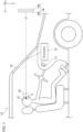
- As illustrated in
FIG. 1 , amovable body 10 incorporates acamera system 50 according to one embodiment of the present disclosure. Thecamera system 50 includes acamera 11, afirst controller 1, and asecond controller 2. Themovable body 10 may include adriving support system 100 including thecamera system 50. - Examples of the movable body in the present disclosure include a vehicle, a vessel, and an aircraft. Examples of the vehicle include an automobile, an industrial vehicle, a railroad vehicle, a community vehicle, and a fixed-wing aircraft traveling on a runway. Examples of the automobile include a passenger vehicle, a truck, a bus, a motorcycle, and a trolley bus. Examples of the industrial vehicle include an industrial vehicle for agriculture and an industrial vehicle for construction. Examples of the industrial vehicle include a forklift and a golf cart. Examples of the industrial vehicle for agriculture include a tractor, a cultivator, a transplanter, a binder, a combine, and a lawn mower. Examples of the industrial vehicle for construction include a bulldozer, a scraper, a power shovel, a crane vehicle, a dump truck, and a road roller. Examples of the vehicle include man-powered vehicles. The classification of the vehicle is not limited to the above examples. Examples of the automobile include an industrial vehicle travelling on a road. One type of vehicle may fall within multiple classes. Examples of the vessel include a jet ski, a boat, and a tanker. Examples of the aircraft include a fixed-wing aircraft and a rotary-wing aircraft.
- In the example described below, the
movable body 10 is a passenger vehicle. Themovable body 10 may be any of the above examples instead of a passenger vehicle. Thecamera 11 may be attached to themovable body 10. Thecamera 11 can capture an image of an area including aneye box 16 of adriver 13 of themovable body 10. Theeye box 16 is an area in a real space in whicheyes 5 of thedriver 13 are expected to be located based on, for example, the body shape, the posture, and changes in the posture of thedriver 13. Theeye box 16 may have any shape. Theeye box 16 may include a planar area or a three-dimensional (3D) area. Thecamera 11 may be attached at any position inside or outside themovable body 10. For example, thecamera 11 may be inside a dashboard in themovable body 10. -
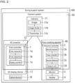
FIG. 2 is a block diagram of a driving support system. Thedriving support system 100 may include a3D projector 12 and adriver monitoring apparatus 60. Thedriving support system 100 may include thecamera system 50. The driver monitoringapparatus 60 and the3D projector 12 share thecamera system 50. Thecamera system 50 includes thecamera 11, thefirst controller 1, and thesecond controller 2. Thefirst controller 1 is included in the3D projector 12. Thesecond controller 2 is included in thedriver monitoring apparatus 60. - The
camera 11 may function both as an infrared camera and a visible light camera. Thecamera 11 can capture an image of thedriver 13 of a vehicle and divide the captured image into divisional images to be transmitted separately. Thecamera 11 includes, for example, animager 11a, animage divider 11b, and atransmitter 11c. Theimager 11a may include, for example, a charge-coupled device (CCD) image sensor or a complementary metal-oxide semiconductor (CMOS) image sensor. Theimager 11a may capture an image of a substantially upper half of the body of thedriver 13 including, for example, the face, the shoulders, and the arms. The captured image generated by theimager 11a is output to theimage divider 11b. Theimage divider 11b divides the captured image output from theimager 11a into multiple divisional images. Theimage divider 11b may divide the captured image into at least two divisional images. Such image division will be described in detail later. The divisional images obtained by theimage divider 11b are externally transmitted by thetransmitter 11c from thecamera 11. Thetransmitter 11c may separately transmit the multiple divisional images one by one. When the captured image is divided into, for example, two divisional images, thetransmitter 11c may first transmit one of the two divisional images and then transmit the other divisional image sequentially. When the captured image is divided into three or more divisional images, thetransmitter 11c may also transmit the divisional images sequentially. Theimage divider 11b may assign an identification code to each of the divisional images. - The captured divisional images are transmitted from the
camera 11 to thefirst controller 1 and thesecond controller 2. Thecamera 11 may output the captured divisional images to the3D projector 12 through wired communication or wireless communication. The wired communication may include, for example, a controller area network (CAN). Thefirst controller 1 may be included in the3D projector 12. In response to receiving, from thecamera 11, at least one of the captured divisional images, thefirst controller 1 performs a first detection process to detect first information associated with the positions of theeyes 5 of thedriver 13. The3D projector 12 may function as a head-up display. The first information associated with the positions of theeyes 5 of thedriver 13 may indicate, for example, the pupil positions. The first detection process may include detecting the pupil positions of thedriver 13 based on an image. Thesecond controller 2 may be included in thedriver monitoring apparatus 60. In response to receiving all the divisional captured images from thecamera 11, thesecond controller 2 generates the captured image by composition and performs a second detection process to detect second information associated with the driving state of thedriver 13. Thedriver monitoring apparatus 60 may function as a driver monitoring system. The second information associated with the driving state of thedriver 13 may indicate, for example, the face orientation of the driver 13 (e.g., the face of thedriver 13 looking to a side, looking to the front, or looking down). The second detection process may include detecting the face orientation of thedriver 13 based on an image. -
FIG. 3 is a schematic diagram illustrating a first example of image division. Theimage divider 11b divides a captured image P generated by theimager 11a into a first image P1 including an area expected to include theeyes 5 of thedriver 13 and a second image P2 excluding the first image P1. Thetransmitter 11c transmits the first image P1 before transmitting the second image P2. Thefirst controller 1 and thesecond controller 2 receive the first image P1 transmitted from thetransmitter 11c. In the image division, theimage divider 1 1b may change the position of the first image P1 in the captured image P for each captured image P. In this case, information indicating the position of the first image P1 in the captured image P to be divided may be added to the first image P1 to be transmitted. In the image division, theimage divider 11b may use the same position as the position of the first image P1 in the captured image P for every captured image P. In this case, the information indicating the position of the first image P1 in the captured image to be divided may not be added to the first image P1 to be transmitted. The information indicating the position of the first image P1 in the captured image P may be prestored in thefirst controller 1 and thesecond controller 2. - The
first controller 1 includes afirst receiver 1a, afirst detector 1b, and adisplay controller 1c. Thefirst receiver 1a receives at least one of the images transmitted from thetransmitter 11c in thecamera 11. For example, thefirst receiver 1a may receive, of the divisional images obtained by dividing the captured image P, an image that is first transmitted from thetransmitter 11c. Thefirst receiver 1a receiving an image may no longer receive other divisional images obtained by dividing the captured image P. In this example, thefirst receiver 1a receives the first image P1 that is first transmitted from thetransmitter 11c. Thefirst receiver 1a does not receive the second image P2 that is subsequently transmitted from thetransmitter 11c. Thefirst detector 1b detects the pupil positions as the first detection process. Thefirst detector 1b can detect the pupil positions based on the first image P1 including theeyes 5 of thedriver 13. For the first image P1 with the information indicating the position of the first image P1 in the captured image P being added, the added information may be used. For the first image P1 with the information indicating the position of the first image P1 in the captured image P being added, thefirst detector 1b obtains pupil positional information using the added information. For the first image P1 without the information indicating the position of the first image P1 in the captured image P, thefirst detector 1b obtains the pupil positional information using the prestored positional information. Thedisplay controller 1c controls image display in the3D projector 12 based on the pupil positional information detected by thefirst detector 1b. - The
second controller 2 includes asecond receiver 2a, animage compositor 2b, asecond detector 2c, and anoutput unit 2d. Thesecond receiver 2a receives all the images transmitted from thetransmitter 11c in thecamera 11. Theimage compositor 2b composites all the images received by thesecond receiver 2a and generates a composite captured image P'. In this example, thesecond receiver 2a receives the first image P1 and the second image P2 that are transmitted from thetransmitter 11c. Theimage compositor 2b composites the first image P1 and the second image P2 received by thesecond receiver 2a and generates the composite captured image P'. Thesecond detector 2c performs the second detection process based on the composite captured image P' composite by theimage compositor 2b. The captured image P includes, for example, the upper half of the body of thedriver 13 and thus allows detection of the face orientation of thedriver 13. Theoutput unit 2d outputs information about the face orientation detected by thesecond detector 2c. - The first information associated with the positions of the eyes of a driver used in the
3D projector 12 is to be detected faster than the second information associated with the driving state of the driver used in thedriver monitoring apparatus 60. Thefirst controller 1 can perform the first detection process and detect the first information by simply receiving at least one of the images transmitted from thecamera 11. Thesecond controller 2 can perform the second detection process and detect the second information by receiving all the images transmitted from thecamera 11 and compositing the images together. The first detection process allows faster detection than the second detection process. This allows transmission of images appropriate for the two different detection processes, thus improving the processing speed. -
FIG. 4 is a schematic diagram illustrating a second example of image division. Theimage divider 11b divides the captured image P generated by theimager 11a into multiple downsampled images each including a smaller number of pixels than the captured image P. In this example, theimage divider 11b divides the captured image P into four downsampled images LP1 to LP4. The number of pixels in each of the downsampled images LP1 to LP4 is a quarter of the number of pixels in the captured image P. For example, three pixels of four consecutive pixels are removed. This processing is repeated every four pixels to obtain the downsampled image LP1 with a quarter of the number of pixels. The downsampled images LP2 to LP4 are each obtained by removing, of four consecutive pixels in each set, three pixels at positions different from previously removed three pixels, or in other words, retaining, in each set of four such pixels, a single pixel at a position different from a previously retained pixel. Thetransmitter 11c transmits the downsampled images LP1 to LP4 sequentially. Thefirst controller 1 and thesecond controller 2 receive the downsampled image LP1 that is first transmitted from thetransmitter 11c. - The
first receiver 1a in thefirst controller 1 receives the downsampled image LP1 that is first transmitted from thetransmitter 11c. Thefirst receiver 1a does not receive the downsampled images LP2 to LP4 that are subsequently transmitted from thetransmitter 11c. Thefirst detector 1b can detect the pupil positions based on the downsampled image LP1. Thedisplay controller 1c controls image display in the3D projector 12 based on the pupil positional information detected by thefirst detector 1b. - The
second receiver 2a in thesecond controller 2 receives all the downsampled images LP1 to LP4 that are transmitted from thetransmitter 11c. Theimage compositor 2b composites the downsampled images LP1 to LP4 received by thesecond receiver 2a and generates the composite captured image P'. Thesecond detector 2c performs the second detection process based on the composite captured image P' composited by theimage compositor 2b. The captured image P includes, for example, the upper half of the body of thedriver 13 and thus allows detection of the face orientation of thedriver 13. Theoutput unit 2d outputs information about the face orientation detected by thesecond detector 2c. - The
camera system 50 may include, for example, a sensor. The sensor may be, for example, an ultrasonic sensor or an optical sensor. Thecamera system 50 may detect the position of the head of thedriver 13 with the sensor, and may detect the pupil positions of thedriver 13 based on the position of the head. Thecamera 11 may use two or more sensors to detect the pupil positions of thedriver 13 using coordinates in a 3D space. - The
first controller 1 and thesecond controller 2 may be, for example, processors. Thefirst controller 1 and thesecond controller 2 may include one or more processors. The processors may include a general-purpose processor that reads a specific program to perform a specific function, and a processor dedicated to specific processing. The dedicated processor may include an ASIC (application-specific integrated circuit). The processors may include a programmable logic device (PLD). The PLD may include a field-programmable gate array (FPGA). Thefirst controller 1 may be either a system on a chip (SoC) or a system in a package (an SiP) in which one or more processors cooperate with other components. - The
3D projector 12 will now be described.FIG. 5 is a schematic diagram of an example 3D projector. The3D projector 12 may control an image to be projected based on the pupil positional information that is the first information. The3D projector 12 may be at any position inside or outside themovable body 10. For example, the3D projector 12 may be inside the dashboard in themovable body 10. The3D projector 12 emits image light toward awindshield 15. The image light may be emitted, for example, through an opening in ahousing 120. - The
windshield 15 reflects image light emitted from the3D projector 12. The image light reflected from thewindshield 15 reaches theeye box 16. The solid arrow inFIG. 1 indicates a path traveled by at least a part of image light emitted from the3D projector 12 to reach theeye box 16. The path traveled by image light is also referred to as an optical path. With theeyes 5 of thedriver 13 located in theeye box 16 receiving image light, thedriver 13 can view avirtual image 14. Thevirtual image 14 is on the dot-dash line extending frontward from the path extending from thewindshield 15 to theeyes 5. The3D projector 12 can function as a head-up display that enables thedriver 13 to view thevirtual image 14. InFIG. 1 , the direction in which theeyes 5 of thedriver 13 are aligned corresponds to x-direction. The vertical direction corresponds to y-direction. - As illustrated in
FIG. 5 , the3D projector 12 includes a3D display device 17 and anoptical element 18. The3D display device 17 may include abacklight 19, adisplay 20 including adisplay surface 20a, abarrier 21, and thefirst controller 1. The3D display device 17 may further include a communicator 22. The3D display device 17 may further include astorage 23. The3D projector 12 may include, for example, thehousing 120. Thehousing 120 accommodates the3D display device 17 and theoptical element 18. - The
optical element 18 may include afirst mirror 18a and asecond mirror 18b. At least one of thefirst mirror 18a or thesecond mirror 18b may have optical power. In the present embodiment, thefirst mirror 18a is a concave mirror having optical power. Thesecond mirror 18b is a plane mirror. Theoptical element 18 may function as a magnifying optical system that magnifies an image displayed by the3D display device 17. The arrowed dot-dash line inFIG. 5 indicates the traveling path of at least a part of image light emitted from the3D display device 17 to be reflected from thefirst mirror 18a and thesecond mirror 18b and then exit the3D projector 12. The image light emitted from the3D projector 12 reaches thewindshield 15, is reflected from thewindshield 15, and then reaches theeyes 5 of thedriver 13. This allows thedriver 13 to view the image displayed by the3D display device 17. - The
optical element 18 and thewindshield 15 allow image light emitted from the3D display device 17 to reach theeyes 5 of thedriver 13. Theoptical element 18 and thewindshield 15 may be included in anoptical system 30. In other words, theoptical system 30 includes theoptical element 18 and thewindshield 15. Theoptical system 30 allows image light emitted from the3D display device 17 to travel along the optical path indicated by the dot-dash line and reach theeyes 5 of thedriver 13. Theoptical system 30 may control the traveling direction of image light to enlarge or reduce an image viewable by thedriver 13. Theoptical system 30 may control the traveling direction of image light to deform an image viewable by thedriver 13 based on a predetermined matrix. - The
optical element 18 may have a structure different from the illustrated structure. Theoptical element 18 may include a concave mirror, a convex mirror, or a plane mirror. The concave mirror or the convex mirror may be at least partially spherical or aspherical. Theoptical element 18 may include one component or may include three or more components, instead of two components. Theoptical element 18 may include a lens instead of or in addition to a mirror. The lens may be a concave lens or a convex lens. The lens may be at least partially spherical or aspherical. - The
backlight 19 is more away from thedriver 13 than thedisplay 20 and thebarrier 21 on the optical path of image light. Thebacklight 19 emits light toward thebarrier 21 and thedisplay 20. At least a part of light emitted from thebacklight 19 travels along the optical path indicated by the dot-dash line and reaches theeyes 5 of thedriver 13. Thebacklight 19 may include a light emitter such as a light-emitting diode (LED), an organic EL element, or an inorganic EL element. Thebacklight 19 may have any structure that allows control of the light intensity and the light intensity distribution. - The
display 20 includes a display panel. Thedisplay 20 may be, for example, a liquid-crystal device such as a liquid-crystal display (LCD). In the present embodiment, thedisplay 20 includes a transmissive liquid-crystal display panel. Thedisplay 20 is not limited to this, and may include any of various display panels. - The
display 20 includes multiple pixels and controls the transmittance of light from thebacklight 19 incident on each pixel to emit image light that then reaches theeyes 5 of thedriver 13. Thedriver 13 views an image formed by image light emitted from each pixel in thedisplay 20. - The
barrier 21 defines the traveling direction of incident light. With thebarrier 21 nearer thebacklight 19 than thedisplay 20, light emitted from thebacklight 19 enters thebarrier 21 and then enters thedisplay 20. In this case, thebarrier 21 blocks or attenuates a part of light emitted from thebacklight 19 and transmits another part of the light to thedisplay 20. Thedisplay 20 emits incident light traveling in the direction defined by thebarrier 21 as image light traveling in the same direction. With thedisplay 20 nearer thebacklight 19 than thebarrier 21, light emitted from thebacklight 19 enters thedisplay 20 and then enters thebarrier 21. In this case, thebarrier 21 blocks or attenuates a part of image light emitted from thedisplay 20 and transmits another part of the image light to theeyes 5 of thedriver 13. - Independently of whether the
display 20 or thebarrier 21 is nearer thedriver 13, thebarrier 21 can control the traveling direction of image light. Thebarrier 21 allows a part of image light emitted from thedisplay 20 to reach one of theleft eye 5L and theright eye 5R (refer toFIG. 4 ) of thedriver 13, and another part of the image light to reach the other of theleft eye 5L and theright eye 5R of thedriver 13. In other words, thebarrier 21 directs at least a part of image light toward theleft eye 5L of thedriver 13 and toward theright eye 5R of thedriver 13. Theleft eye 5L is also referred to as a first eye, and theright eye 5R as a second eye. In the present embodiment, thebarrier 21 is located between thebacklight 19 and thedisplay 20. In other words, light emitted from thebacklight 19 first enters thebarrier 21 and then enters thedisplay 20. - The
barrier 21 defines the traveling direction of image light to allow each of theleft eye 5L and theright eye 5R of thedriver 13 to receive different image light. Each of theleft eye 5L and theright eye 5R of thedriver 13 can thus view a different image. -
FIG. 6 is a schematic diagram describing the relationship between the eyes of a driver, a display, and a barrier. As illustrated inFIG. 6 , thedisplay 20 includes left-eye viewing areas 201L viewable by theleft eye 5L of thedriver 13 and right-eye viewing areas 201R viewable by theright eye 5R of thedriver 13 on thedisplay surface 20a. Thedisplay 20 displays a parallax image including left-eye images viewable by theleft eye 5L of thedriver 13 and right-eye images viewable by theright eye 5R of thedriver 13. A parallax image refers to an image projected to theleft eye 5L and theright eye 5R of thedriver 13 to provide parallax between the two eyes of thedriver 13. Thedisplay 20 displays left-eye images on the left-eye viewing areas 201L and right-eye images on the right-eye viewing areas 201R. In other words, thedisplay 20 displays a parallax image on the left-eye viewing areas 201L and the right-eye viewing areas 201R. The left-eye viewing areas 201L and the right-eye viewing areas 201R are arranged in u-direction indicating a parallax direction. The left-eye viewing areas 201L and the right-eye viewing areas 201R may extend in v-direction orthogonal to the parallax direction, or in a direction inclined with respect to v-direction at a predetermined angle. In other words, the left-eye viewing areas 201L and the right-eye viewing areas 201R may be arranged alternately in a predetermined direction including a component in the parallax direction. The pitch between the alternately arranged left-eye viewing areas 201L and right-eye viewing areas 201R is also referred to as a parallax image pitch. The left-eye viewing areas 201L and the right-eye viewing areas 201R may be spaced from each other or adjacent to each other. Thedisplay 20 may further include a display area to display a planar image on thedisplay surface 20a. The planar image provides no parallax between theeyes 5 of thedriver 13 and is not viewed stereoscopically. - As illustrated in
FIG. 6 , thebarrier 21 includesopen portions 21b and light-blockingportions 21a. Thebarrier 21 located nearer thedriver 13 than thedisplay 20 on the optical path of image light controls the transmittance of image light emitted from thedisplay 20. Theopen portions 21b transmit light entering thebarrier 21 from thedisplay 20. Theopen portions 21b may transmit light with a transmittance of a first predetermined value or greater. The first predetermined value may be, for example, 100% or a value close to 100%. The light-blockingportions 21a block light entering thebarrier 21 from thedisplay 20. The light-blockingportions 21a may transmit light with a transmittance of a second predetermined value or less. The second predetermined value may be, for example, 0% or a value close to 0%. The first predetermined value is greater than the second predetermined value. - The
open portions 21b and the light-blockingportions 21a are arranged alternately in u-direction indicating the parallax direction. The boundaries between theopen portions 21b and the light-blockingportions 21a may extend in v-direction orthogonal to the parallax direction as illustrated inFIG. 6 , or in a direction inclined with respect to v-direction at a predetermined angle. In other words, theopen portions 21b and the light-blockingportions 21a may be arranged alternately in a predetermined direction including a component in the parallax direction. - In the present embodiment, the
barrier 21 is more away from thedriver 13 than thedisplay 20 on the optical path of image light. Thebarrier 21 controls the transmittance of light directed from thebacklight 19 to thedisplay 20. Theopen portions 21b transmit light directed from thebacklight 19 to thedisplay 20. The light-blockingportions 21a block light directed from thebacklight 19 to thedisplay 20. This structure allows light entering thedisplay 20 to travel in a predetermined direction. Thus, thebarrier 21 can control a part of image light to reach theleft eye 5L of thedriver 13, and another part of the image light to reach theright eye 5R of thedriver 13. - The
barrier 21 may include a liquid crystal shutter. The liquid crystal shutter can control the transmittance of light in accordance with a voltage applied. The liquid crystal shutter may include multiple pixels and control the transmittance of light for each pixel. The liquid crystal shutter can form an area with high light transmittance or an area with low light transmittance in an intended shape. Theopen portions 21b in thebarrier 21 including a liquid crystal shutter may have a transmittance of the first predetermined value or greater. The light-blockingportions 21a in thebarrier 21 including a liquid crystal shutter may have a transmittance of the second predetermined value or less. The first predetermined value may be greater than the second predetermined value. The ratio of the second predetermined value to the first predetermined value may be set to 1/100 in one example. The ratio of the second predetermined value to the first predetermined value may be set to 1/1000 in another example. Thebarrier 21 including theopen portions 21b and the light-blockingportions 21a that can shift is also referred to as an active barrier. - The
first controller 1 controls thedisplay 20. Thefirst controller 1 may control thebarrier 21 that is an active barrier. Thefirst controller 1 may control thebacklight 19. Thedisplay controller 1c in thefirst controller 1 controls thedisplay 20 based on the pupil positional information detected by thefirst detector 1b. Thefirst controller 1 may control at least one of thebarrier 21 or thebacklight 19 based on the pupil positional information. - The communicator 22 may include an interface that can communicate with an external device. The communicator 22 may obtain, for example, information about images from the external device and output the information to the
first controller 1. The interface that can perform communication in the present disclosure may include, for example, a physical connector and a wireless communication device. The physical connector may include an electric connector for transmission with electric signals, an optical connector for transmission with optical signals, and an electromagnetic connector for transmission with electromagnetic waves. The electric connector may include a connector complying with IEC 60603, a connector complying with the USB standard, or a connector used for an RCA terminal. The electric connector may include a connector used for an S terminal specified by EIAJ CP-121aA or a connector used for a D terminal specified by EIAJ RC-5237. The electric connector may include a connector complying with the HDMI (registered trademark) standard or a connector used for a coaxial cable including a BNC (British Naval Connector, also known as, for example, a Baby-series N Connector). The optical connector may include a connector complying with IEC 61754. The wireless communication device may include a wireless communication device complying with the Bluetooth (registered trademark) standard and a wireless communication device complying with other standards including IEEE 8021a. The wireless communication device includes at least one antenna. - The
storage 23 may store various information sets or programs for causing the components of the3D display device 17 to operate. Thestorage 23 may include, for example, a semiconductor memory. Thestorage 23 may function as a work memory for thefirst controller 1. Thestorage 23 may be included in thefirst controller 1. - As illustrated in
FIG. 6 , light emitted from thebacklight 19 passes through thebarrier 21 and thedisplay 20 to reach theeyes 5 of thedriver 13. The broken lines indicate the paths traveled by light from thebacklight 19 to reach theeyes 5. The light through theopen portions 21b in thebarrier 21 to reach theright eye 5R passes through the right-eye viewing areas 201R in thedisplay 20. In other words, light through theopen portions 21b allows theright eye 5R to view the right-eye viewing areas 201R. The light through theopen portions 21b in thebarrier 21 to reach theleft eye 5L passes through the left-eye viewing areas 201L in thedisplay 20. In other words, light through theopen portions 21b allows theleft eye 5L to view the left-eye viewing areas 201L. - The
display 20 displays right-eye images on the right-eye viewing areas 201R and left-eye images on the left-eye viewing areas 201L. Thus, thebarrier 21 allows image light for the left-eye images to reach theleft eye 5L and image light for the right-eye images to reach theright eye 5R. More specifically, theopen portions 21b allow image light for the left-eye images to reach theleft eye 5L of thedriver 13 and image light for the right-eye images to reach theright eye 5R of thedriver 13. The3D display device 17 with this structure can project a parallax image to the two eyes of thedriver 13. Thedriver 13 views a parallax image with theleft eye 5L and theright eye 5R to view the image stereoscopically. - Image light passing through the
open portions 21b in thebarrier 21 and emitted from thedisplay surface 20a of thedisplay 20 at least partially reaches thewindshield 15 through theoptical element 18. The image light is reflected from thewindshield 15 and reaches theeyes 5 of thedriver 13. This allows theeyes 5 of thedriver 13 to view a firstvirtual image 14a located more away in the negative z-direction than thewindshield 15. The firstvirtual image 14a corresponds to the image appearing on thedisplay surface 20a. Theopen portions 21b and the light-blockingportions 21a in thebarrier 21 form a secondvirtual image 14b in front of thewindshield 15 and closer to thewindshield 15 than the firstvirtual image 14a. As illustrated inFIG. 5 , thedriver 13 can view an image with thedisplay 20 appearing to be at the position of the firstvirtual image 14a and thebarrier 21 appearing to be at the position of the secondvirtual image 14b. - The
3D display device 17 emits image light for the image appearing on thedisplay surface 20a in the direction defined by thebarrier 21. Theoptical element 18 directs the image light to thewindshield 15. Theoptical element 18 may reflect or refract the image light. Thewindshield 15 reflects the image light to direct the light to theeyes 5 of thedriver 13. The image light entering theeyes 5 of thedriver 13 causes thedriver 13 to view a parallax image as thevirtual image 14. Thedriver 13 views thevirtual image 14 stereoscopically. An image corresponding to the parallax image in thevirtual image 14 is also referred to as a parallax virtual image. The parallax virtual image is a parallax image projected through theoptical system 30. An image corresponding to the planar image in thevirtual image 14 is also referred to as a planar virtual image. The planar virtual image is a planar image projected through theoptical system 30. - The
driver monitoring apparatus 60 will now be described. As illustrated inFIG. 2 , thedriver monitoring apparatus 60 includes thesecond controller 2, amonitor 3, and anotifier 4. As described above, theoutput unit 2d in thesecond controller 2 outputs the second information detected by thesecond detector 2c. The second information is associated with the driving state of a driver. Themonitor 3 determines the driving state of thedriver 13 based on the second information and determines whether a notification such as a warning is to be provided to thedriver 13. In response to themonitor 3 determining that a notification is to be provided to thedriver 13, thenotifier 4 provides, for example, a warning. The warning notification includes, for example, displaying a warning message, displaying a warning image, reading a warning message with a voice, and outputting an alarm sound. When the second information indicates, for example, the face orientation of thedriver 13, themonitor 3 may determine whether thedriver 13 is engaging in normal driving or distracted driving based on the information about the face orientation. For thedriver 13 engaging in distracted driving, themonitor 3 may determine that a warning is to be provided, and thenotifier 4 may provide the warning to thedriver 13. - Another example camera system will now be described.
FIGs. 7A and 7B are schematic diagrams of a camera system including a relay.FIG. 7A illustrates acamera system 50A in the first example of image division.FIG. 7B illustrates thecamera system 50A in the second example of image division. Thecamera system 50A differs from theabove camera system 50 in including arelay 6. Thecamera system 50A includes thecamera 11, therelay 6, thefirst controller 1, and thesecond controller 2. Therelay 6 receives images transmitted from thecamera 11 and transmits the received images to thefirst controller 1 and thesecond controller 2. The images from thecamera 11 received by therelay 6 are obtained by thecamera 11 dividing a captured image in the same manner as above. Therelay 6 may select, from the images received from thecamera 11, images to be transmitted to thefirst controller 1 and thesecond controller 2. Therelay 6 may transmit an image received from thecamera 11 first to thefirst controller 1 and thesecond controller 2, and transmit subsequently received images to thesecond controller 2 without transmitting them to thefirst controller 1. - In the first example of image division, the
camera 11 transmits the first image P1 and the second image P2 sequentially. Therelay 6 receives the first image P1 and the second image P2 sequentially. Therelay 6 transmits the first image P1 to thefirst controller 1 and the first image P1 and the second image P2 to thesecond controller 2. In response to receiving the first image P1, therelay 6 may transmit the first image P1 to thefirst controller 1 independently of whether therelay 6 receives the second image P2. In theabove camera system 50, thefirst controller 1 determines to receive no second image P2 after receiving the first image P1. In thecamera system 50A, therelay 6 transmits, to thefirst controller 1, the first image P1 alone and does not transmit the second image P2. Thefirst controller 1 may receive the first image P1 transmitted from therelay 6 alone and may not determine to receive no second image P2. - In the second example of image division, the
camera 11 transmits the downsampled images LP1 to LP4 sequentially. Therelay 6 receives the downsampled images LP1 to LP4 sequentially. For example, the image received by therelay 6 first from thecamera 11 is the downsampled image LP1. Therelay 6 transmits the downsampled image LP1 to thefirst controller 1 and the downsampled images LP1 to LP4 to thesecond controller 2. In response to receiving the downsampled image LP1, therelay 6 may transmit the downsampled image LP1 to thefirst controller 1 independently of whether therelay 6 receives the other downsampled images LP2 to LP4. Therelay 6 may transmit a downsampled image received from thecamera 11 first to thefirst controller 1. In theabove camera system 50, thefirst controller 1 determines to receive no downsampled images LP2 to LP4 after receiving the downsampled image LP1. In thecamera system 50A, therelay 6 transmits the downsampled image LP1 alone to thefirst controller 1. Thefirst controller 1 may receive the downsampled image LP1 transmitted from therelay 6 alone and may not determine to receive no downsampled images LP2 to LP4. - The structure according to the present disclosure is not limited to the structure described in the above embodiments, but may be modified or altered variously. For example, the functions of the components are reconfigurable unless any contradiction arises. Multiple components may be combined into a single unit, or a single component may be divided into separate units.
- In the present disclosure, the first, the second, or others are identifiers for distinguishing the components. The identifiers of the components distinguished with the first, the second, and others in the present disclosure are interchangeable. For example, the first eye can be interchangeable with the second eye. The identifiers are to be interchanged together. The components for which the identifiers are interchanged are also to be distinguished from one another. The identifiers may be eliminated. The components without such identifiers can be distinguished with reference numerals. The identifiers such as the first and the second in the present disclosure alone should not be used to determine the order of components or to suggest the existence of smaller or larger number identifiers.
- In the present disclosure, x-axis, y-axis, and z-axis are used for ease of explanation and may be interchangeable with one another. The orthogonal coordinate system including x-axis, y-axis, and z-axis is used to describe the structures according to the present disclosure. The positional relationship between the components in the present disclosure is not limited to being orthogonal.
- The present disclosure may be implemented in the following forms.
- A camera system according to one embodiment of the present disclosure includes a camera, a first controller, and a second controller. The camera captures an image of a driver of a vehicle, divides the captured image into a plurality of divisional captured images, and transmits the plurality of divisional captured images separately. The first controller performs a first detection process to detect first information associated with a position of an eye of the driver in response to receiving at least one divisional captured image of the plurality of divisional captured images from the camera. The second controller generates, in response to receiving all of the plurality of divisional captured images from the camera, a captured image by composition, and performs a second detection process to detect second information associated with a driving state of the driver.
- A driving support system according to one embodiment of the present disclosure includes the camera system described above, a display, a barrier, a display controller, and a monitor. The display displays a parallax image to be projected to two eyes of a driver. The barrier defines a traveling direction of image light of the parallax image to generate parallax between the two eyes. The display controller controls the display based on the first information. The monitor monitors a driving state of the driver based on the second information.
- The camera system according to one embodiment of the present disclosure transmits images appropriate for the two different detection processes, thus improving the processing speed for such detection.
- The driving support system according to one embodiment of the present disclosure improves the processing speed in displaying a parallax image and monitoring a driving state.
- Although embodiments of the present disclosure have been described in detail, the present disclosure is not limited to the embodiments described above, and may be changed or modified in various manners without departing from the spirit and scope of the present disclosure. The components described in the above embodiments may be entirely or partially combined as appropriate unless any contradiction arises.
-
- 1
- first controller
- 1a
- first receiver
- 1b
- first detector
- 1c
- display controller
- 2
- second controller
- 2a
- second receiver
- 2b
- image compositor
- 2c
- second detector
- 2d
- output unit
- 3
- monitor
- 4
- notifier
- 5
- eye (5L: left eye, 5R: right eye)
- 6
- relay
- 10
- movable body
- 11
- camera
- 11a
- imager
- 11b
- image divider
- 11c
- transmitter
- 12
- 3D projector
- 13
- driver
- 14
- virtual image (14a: first virtual image, 14b: second virtual image)
- 15
- windshield
- 16
- eye box
- 17
- 3D display device
- 18
- optical element (18a: first mirror, 18b: second mirror)
- 19
- backlight
- 20
- display (20a: display surface)
- 201L
- left-eye viewing area
- 201R
- right-eye viewing area
- 21
- barrier (21a: light-blocking portion, 21b: open portion)
- 22
- communicator
- 23
- storage
- 30
- optical system
- 50, 50A
- camera system
- 60
- driver monitoring apparatus
- 100
- driving support system
Claims (8)
- A camera system, comprising:a camera configured to capture an image of a driver of a vehicle, divide the captured image into a plurality of divisional captured images, and transmit the plurality of divisional captured images separately;a first controller configured to perform a first detection process to detect first information associated with a position of an eye of the driver in response to receiving at least one divisional captured image of the plurality of divisional captured images from the camera; anda second controller configured to generate, in response to receiving all of the plurality of divisional captured images from the camera, a composited captured image by composition, and perform a second detection process to detect second information associated with a driving state of the driver.
- The camera system according to claim 1, wherein
the camera divides the captured image into a first image including an area expected to include the eye of the driver and a second image excluding the first image, and transmits the first image before transmitting the second image. - The camera system according to claim 2, wherein
the first controller receives the first image without receiving the second image. - The camera system according to claim 2, further comprising:
a relay configured to transmit, of the first image and the second image transmitted from the camera, the first image to the first controller without transmitting the second image. - The camera system according to claim 1, wherein
the camera divides the captured image into a plurality of downsampled images each including a smaller number of pixels than the captured image. - The camera system according to claim 5, wherein
the first controller receives at least one downsampled image of the plurality of downsampled images, and subsequently avoids receiving the other downsampled images. - The camera system according to claim 5, further comprising:
a relay configured not to transmit, after transmitting at least one downsampled image of the plurality of downsampled images transmitted from the camera, the other downsampled images. - A driving support apparatus, comprising:the camera system according to any one of claims 1 to 7;a display configured to display a parallax image to be projected to two eyes of a driver;a barrier configured to define a traveling direction of image light of the parallax image to generate parallax between the two eyes;a display controller configured to control the display based on the first information; anda monitor configured to monitor a driving state of the driver based on the second information.
Applications Claiming Priority (2)
| Application Number | Priority Date | Filing Date | Title |
|---|---|---|---|
| JP2020127720A JP2022024890A (en) | 2020-07-28 | 2020-07-28 | Camera system and driving support system |
| PCT/JP2021/026793 WO2022024814A1 (en) | 2020-07-28 | 2021-07-16 | Camera system and driving assistance system |
Publications (1)
| Publication Number | Publication Date |
|---|---|
| EP4191995A1 true EP4191995A1 (en) | 2023-06-07 |
Family
ID=80036832
Family Applications (1)
| Application Number | Title | Priority Date | Filing Date |
|---|---|---|---|
| EP21851118.6A Pending EP4191995A1 (en) | 2020-07-28 | 2021-07-16 | Camera system and driving assistance system |
Country Status (5)
| Country | Link |
|---|---|
| US (1) | US20230286382A1 (en) |
| EP (1) | EP4191995A1 (en) |
| JP (1) | JP2022024890A (en) |
| CN (1) | CN116209594A (en) |
| WO (1) | WO2022024814A1 (en) |
Family Cites Families (4)
| Publication number | Priority date | Publication date | Assignee | Title |
|---|---|---|---|---|
| JPH06230132A (en) | 1993-02-03 | 1994-08-19 | Nissan Motor Co Ltd | Obstacle detector for vehicle |
| JPH11304428A (en) | 1998-04-22 | 1999-11-05 | Matsushita Electric Ind Co Ltd | Driver monitor device and automobile drive support system |
| JP6176070B2 (en) * | 2013-11-13 | 2017-08-09 | 株式会社デンソー | Gaze direction detector |
| US10871655B2 (en) * | 2016-02-12 | 2020-12-22 | Maxell, Ltd. | Image display apparatus for vehicle |
-
2020
- 2020-07-28 JP JP2020127720A patent/JP2022024890A/en active Pending
-
2021
- 2021-07-16 WO PCT/JP2021/026793 patent/WO2022024814A1/en active Application Filing
- 2021-07-16 US US18/018,511 patent/US20230286382A1/en active Pending
- 2021-07-16 EP EP21851118.6A patent/EP4191995A1/en active Pending
- 2021-07-16 CN CN202180059732.6A patent/CN116209594A/en active Pending
Also Published As
| Publication number | Publication date |
|---|---|
| WO2022024814A1 (en) | 2022-02-03 |
| CN116209594A (en) | 2023-06-02 |
| US20230286382A1 (en) | 2023-09-14 |
| JP2022024890A (en) | 2022-02-09 |
Similar Documents
| Publication | Publication Date | Title |
|---|---|---|
| EP3876032A1 (en) | Image display device, image display system, and moving body | |
| EP4116128A1 (en) | Camera apparatus, windshield, and image display module | |
| EP4191995A1 (en) | Camera system and driving assistance system | |
| EP3951480A1 (en) | Image display module, image display system, moving body, image display method, and image display program | |
| EP4145213A1 (en) | Image display system | |
| EP4303080A1 (en) | Imaging device and three-dimensional display device | |
| EP4155884A1 (en) | Viewpoint detecting device, and display device | |
| EP4262198A1 (en) | Three-dimensional display device, image display system, and moving body | |
| EP3951479A1 (en) | Image display module, mobile object, and concave mirror | |
| EP4155811A1 (en) | Image display module | |
| EP4057049A1 (en) | Head-up display, head-up display system, and moving body | |
| US20230156178A1 (en) | Detection device and image display module | |
| US20230388479A1 (en) | Detection device and image display system | |
| JP2022021866A (en) | Camera system and image display system |
Legal Events
| Date | Code | Title | Description |
|---|---|---|---|
| STAA | Information on the status of an ep patent application or granted ep patent |
Free format text: STATUS: THE INTERNATIONAL PUBLICATION HAS BEEN MADE |
|
| PUAI | Public reference made under article 153(3) epc to a published international application that has entered the european phase |
Free format text: ORIGINAL CODE: 0009012 |
|
| STAA | Information on the status of an ep patent application or granted ep patent |
Free format text: STATUS: REQUEST FOR EXAMINATION WAS MADE |
|
| 17P | Request for examination filed |
Effective date: 20230130 |
|
| AK | Designated contracting states |
Kind code of ref document: A1 Designated state(s): AL AT BE BG CH CY CZ DE DK EE ES FI FR GB GR HR HU IE IS IT LI LT LU LV MC MK MT NL NO PL PT RO RS SE SI SK SM TR |
|
| DAV | Request for validation of the european patent (deleted) | ||
| DAX | Request for extension of the european patent (deleted) | ||
| STAA | Information on the status of an ep patent application or granted ep patent |
Free format text: STATUS: THE APPLICATION HAS BEEN WITHDRAWN |