EP4191797A1 - An electromagnetic interference (emi) grounding protection method for a connector using a multidirectional conductive housing - Google Patents
An electromagnetic interference (emi) grounding protection method for a connector using a multidirectional conductive housing Download PDFInfo
- Publication number
- EP4191797A1 EP4191797A1 EP22207217.5A EP22207217A EP4191797A1 EP 4191797 A1 EP4191797 A1 EP 4191797A1 EP 22207217 A EP22207217 A EP 22207217A EP 4191797 A1 EP4191797 A1 EP 4191797A1
- Authority
- EP
- European Patent Office
- Prior art keywords
- metallic
- outer housing
- emi
- conductive housing
- directional
- Prior art date
- Legal status (The legal status is an assumption and is not a legal conclusion. Google has not performed a legal analysis and makes no representation as to the accuracy of the status listed.)
- Pending
Links
Images


Classifications
-
- H—ELECTRICITY
- H01—ELECTRIC ELEMENTS
- H01R—ELECTRICALLY-CONDUCTIVE CONNECTIONS; STRUCTURAL ASSOCIATIONS OF A PLURALITY OF MUTUALLY-INSULATED ELECTRICAL CONNECTING ELEMENTS; COUPLING DEVICES; CURRENT COLLECTORS
- H01R13/00—Details of coupling devices of the kinds covered by groups H01R12/70 or H01R24/00 - H01R33/00
- H01R13/648—Protective earth or shield arrangements on coupling devices, e.g. anti-static shielding
- H01R13/658—High frequency shielding arrangements, e.g. against EMI [Electro-Magnetic Interference] or EMP [Electro-Magnetic Pulse]
- H01R13/6591—Specific features or arrangements of connection of shield to conductive members
- H01R13/6596—Specific features or arrangements of connection of shield to conductive members the conductive member being a metal grounding panel
-
- B—PERFORMING OPERATIONS; TRANSPORTING
- B60—VEHICLES IN GENERAL
- B60R—VEHICLES, VEHICLE FITTINGS, OR VEHICLE PARTS, NOT OTHERWISE PROVIDED FOR
- B60R16/00—Electric or fluid circuits specially adapted for vehicles and not otherwise provided for; Arrangement of elements of electric or fluid circuits specially adapted for vehicles and not otherwise provided for
- B60R16/02—Electric or fluid circuits specially adapted for vehicles and not otherwise provided for; Arrangement of elements of electric or fluid circuits specially adapted for vehicles and not otherwise provided for electric constitutive elements
- B60R16/03—Electric or fluid circuits specially adapted for vehicles and not otherwise provided for; Arrangement of elements of electric or fluid circuits specially adapted for vehicles and not otherwise provided for electric constitutive elements for supply of electrical power to vehicle subsystems or for
-
- H—ELECTRICITY
- H01—ELECTRIC ELEMENTS
- H01R—ELECTRICALLY-CONDUCTIVE CONNECTIONS; STRUCTURAL ASSOCIATIONS OF A PLURALITY OF MUTUALLY-INSULATED ELECTRICAL CONNECTING ELEMENTS; COUPLING DEVICES; CURRENT COLLECTORS
- H01R13/00—Details of coupling devices of the kinds covered by groups H01R12/70 or H01R24/00 - H01R33/00
- H01R13/40—Securing contact members in or to a base or case; Insulating of contact members
- H01R13/42—Securing in a demountable manner
- H01R13/426—Securing by a separate resilient retaining piece supported by base or case, e.g. collar or metal contact-retention clip
-
- H—ELECTRICITY
- H01—ELECTRIC ELEMENTS
- H01R—ELECTRICALLY-CONDUCTIVE CONNECTIONS; STRUCTURAL ASSOCIATIONS OF A PLURALITY OF MUTUALLY-INSULATED ELECTRICAL CONNECTING ELEMENTS; COUPLING DEVICES; CURRENT COLLECTORS
- H01R13/00—Details of coupling devices of the kinds covered by groups H01R12/70 or H01R24/00 - H01R33/00
- H01R13/46—Bases; Cases
- H01R13/502—Bases; Cases composed of different pieces
-
- H—ELECTRICITY
- H01—ELECTRIC ELEMENTS
- H01R—ELECTRICALLY-CONDUCTIVE CONNECTIONS; STRUCTURAL ASSOCIATIONS OF A PLURALITY OF MUTUALLY-INSULATED ELECTRICAL CONNECTING ELEMENTS; COUPLING DEVICES; CURRENT COLLECTORS
- H01R13/00—Details of coupling devices of the kinds covered by groups H01R12/70 or H01R24/00 - H01R33/00
- H01R13/46—Bases; Cases
- H01R13/52—Dustproof, splashproof, drip-proof, waterproof, or flameproof cases
- H01R13/5202—Sealing means between parts of housing or between housing part and a wall, e.g. sealing rings
-
- H—ELECTRICITY
- H01—ELECTRIC ELEMENTS
- H01R—ELECTRICALLY-CONDUCTIVE CONNECTIONS; STRUCTURAL ASSOCIATIONS OF A PLURALITY OF MUTUALLY-INSULATED ELECTRICAL CONNECTING ELEMENTS; COUPLING DEVICES; CURRENT COLLECTORS
- H01R13/00—Details of coupling devices of the kinds covered by groups H01R12/70 or H01R24/00 - H01R33/00
- H01R13/46—Bases; Cases
- H01R13/53—Bases or cases for heavy duty; Bases or cases for high voltage with means for preventing corona or arcing
-
- H—ELECTRICITY
- H01—ELECTRIC ELEMENTS
- H01R—ELECTRICALLY-CONDUCTIVE CONNECTIONS; STRUCTURAL ASSOCIATIONS OF A PLURALITY OF MUTUALLY-INSULATED ELECTRICAL CONNECTING ELEMENTS; COUPLING DEVICES; CURRENT COLLECTORS
- H01R13/00—Details of coupling devices of the kinds covered by groups H01R12/70 or H01R24/00 - H01R33/00
- H01R13/46—Bases; Cases
- H01R13/533—Bases, cases made for use in extreme conditions, e.g. high temperature, radiation, vibration, corrosive environment, pressure
-
- H—ELECTRICITY
- H01—ELECTRIC ELEMENTS
- H01R—ELECTRICALLY-CONDUCTIVE CONNECTIONS; STRUCTURAL ASSOCIATIONS OF A PLURALITY OF MUTUALLY-INSULATED ELECTRICAL CONNECTING ELEMENTS; COUPLING DEVICES; CURRENT COLLECTORS
- H01R13/00—Details of coupling devices of the kinds covered by groups H01R12/70 or H01R24/00 - H01R33/00
- H01R13/648—Protective earth or shield arrangements on coupling devices, e.g. anti-static shielding
- H01R13/658—High frequency shielding arrangements, e.g. against EMI [Electro-Magnetic Interference] or EMP [Electro-Magnetic Pulse]
- H01R13/6581—Shield structure
-
- H—ELECTRICITY
- H01—ELECTRIC ELEMENTS
- H01R—ELECTRICALLY-CONDUCTIVE CONNECTIONS; STRUCTURAL ASSOCIATIONS OF A PLURALITY OF MUTUALLY-INSULATED ELECTRICAL CONNECTING ELEMENTS; COUPLING DEVICES; CURRENT COLLECTORS
- H01R13/00—Details of coupling devices of the kinds covered by groups H01R12/70 or H01R24/00 - H01R33/00
- H01R13/73—Means for mounting coupling parts to apparatus or structures, e.g. to a wall
-
- H—ELECTRICITY
- H01—ELECTRIC ELEMENTS
- H01R—ELECTRICALLY-CONDUCTIVE CONNECTIONS; STRUCTURAL ASSOCIATIONS OF A PLURALITY OF MUTUALLY-INSULATED ELECTRICAL CONNECTING ELEMENTS; COUPLING DEVICES; CURRENT COLLECTORS
- H01R43/00—Apparatus or processes specially adapted for manufacturing, assembling, maintaining, or repairing of line connectors or current collectors or for joining electric conductors
- H01R43/20—Apparatus or processes specially adapted for manufacturing, assembling, maintaining, or repairing of line connectors or current collectors or for joining electric conductors for assembling or disassembling contact members with insulating base, case or sleeve
-
- H—ELECTRICITY
- H01—ELECTRIC ELEMENTS
- H01R—ELECTRICALLY-CONDUCTIVE CONNECTIONS; STRUCTURAL ASSOCIATIONS OF A PLURALITY OF MUTUALLY-INSULATED ELECTRICAL CONNECTING ELEMENTS; COUPLING DEVICES; CURRENT COLLECTORS
- H01R13/00—Details of coupling devices of the kinds covered by groups H01R12/70 or H01R24/00 - H01R33/00
- H01R13/40—Securing contact members in or to a base or case; Insulating of contact members
- H01R13/42—Securing in a demountable manner
- H01R13/436—Securing a plurality of contact members by one locking piece or operation
- H01R13/4367—Insertion of locking piece from the rear
-
- H—ELECTRICITY
- H01—ELECTRIC ELEMENTS
- H01R—ELECTRICALLY-CONDUCTIVE CONNECTIONS; STRUCTURAL ASSOCIATIONS OF A PLURALITY OF MUTUALLY-INSULATED ELECTRICAL CONNECTING ELEMENTS; COUPLING DEVICES; CURRENT COLLECTORS
- H01R13/00—Details of coupling devices of the kinds covered by groups H01R12/70 or H01R24/00 - H01R33/00
- H01R13/46—Bases; Cases
- H01R13/502—Bases; Cases composed of different pieces
- H01R13/506—Bases; Cases composed of different pieces assembled by snap action of the parts
-
- H—ELECTRICITY
- H01—ELECTRIC ELEMENTS
- H01R—ELECTRICALLY-CONDUCTIVE CONNECTIONS; STRUCTURAL ASSOCIATIONS OF A PLURALITY OF MUTUALLY-INSULATED ELECTRICAL CONNECTING ELEMENTS; COUPLING DEVICES; CURRENT COLLECTORS
- H01R13/00—Details of coupling devices of the kinds covered by groups H01R12/70 or H01R24/00 - H01R33/00
- H01R13/46—Bases; Cases
- H01R13/52—Dustproof, splashproof, drip-proof, waterproof, or flameproof cases
- H01R13/5219—Sealing means between coupling parts, e.g. interfacial seal
-
- H—ELECTRICITY
- H01—ELECTRIC ELEMENTS
- H01R—ELECTRICALLY-CONDUCTIVE CONNECTIONS; STRUCTURAL ASSOCIATIONS OF A PLURALITY OF MUTUALLY-INSULATED ELECTRICAL CONNECTING ELEMENTS; COUPLING DEVICES; CURRENT COLLECTORS
- H01R13/00—Details of coupling devices of the kinds covered by groups H01R12/70 or H01R24/00 - H01R33/00
- H01R13/62—Means for facilitating engagement or disengagement of coupling parts or for holding them in engagement
- H01R13/621—Bolt, set screw or screw clamp
- H01R13/6215—Bolt, set screw or screw clamp using one or more bolts
-
- H—ELECTRICITY
- H01—ELECTRIC ELEMENTS
- H01R—ELECTRICALLY-CONDUCTIVE CONNECTIONS; STRUCTURAL ASSOCIATIONS OF A PLURALITY OF MUTUALLY-INSULATED ELECTRICAL CONNECTING ELEMENTS; COUPLING DEVICES; CURRENT COLLECTORS
- H01R13/00—Details of coupling devices of the kinds covered by groups H01R12/70 or H01R24/00 - H01R33/00
- H01R13/648—Protective earth or shield arrangements on coupling devices, e.g. anti-static shielding
- H01R13/658—High frequency shielding arrangements, e.g. against EMI [Electro-Magnetic Interference] or EMP [Electro-Magnetic Pulse]
- H01R13/6591—Specific features or arrangements of connection of shield to conductive members
- H01R13/65912—Specific features or arrangements of connection of shield to conductive members for shielded multiconductor cable
-
- H—ELECTRICITY
- H01—ELECTRIC ELEMENTS
- H01R—ELECTRICALLY-CONDUCTIVE CONNECTIONS; STRUCTURAL ASSOCIATIONS OF A PLURALITY OF MUTUALLY-INSULATED ELECTRICAL CONNECTING ELEMENTS; COUPLING DEVICES; CURRENT COLLECTORS
- H01R13/00—Details of coupling devices of the kinds covered by groups H01R12/70 or H01R24/00 - H01R33/00
- H01R13/648—Protective earth or shield arrangements on coupling devices, e.g. anti-static shielding
- H01R13/658—High frequency shielding arrangements, e.g. against EMI [Electro-Magnetic Interference] or EMP [Electro-Magnetic Pulse]
- H01R13/6598—Shield material
- H01R13/6599—Dielectric material made conductive, e.g. plastic material coated with metal
-
- H—ELECTRICITY
- H01—ELECTRIC ELEMENTS
- H01R—ELECTRICALLY-CONDUCTIVE CONNECTIONS; STRUCTURAL ASSOCIATIONS OF A PLURALITY OF MUTUALLY-INSULATED ELECTRICAL CONNECTING ELEMENTS; COUPLING DEVICES; CURRENT COLLECTORS
- H01R13/00—Details of coupling devices of the kinds covered by groups H01R12/70 or H01R24/00 - H01R33/00
- H01R13/73—Means for mounting coupling parts to apparatus or structures, e.g. to a wall
- H01R13/74—Means for mounting coupling parts in openings of a panel
- H01R13/748—Means for mounting coupling parts in openings of a panel using one or more screws
-
- H—ELECTRICITY
- H01—ELECTRIC ELEMENTS
- H01R—ELECTRICALLY-CONDUCTIVE CONNECTIONS; STRUCTURAL ASSOCIATIONS OF A PLURALITY OF MUTUALLY-INSULATED ELECTRICAL CONNECTING ELEMENTS; COUPLING DEVICES; CURRENT COLLECTORS
- H01R2201/00—Connectors or connections adapted for particular applications
- H01R2201/26—Connectors or connections adapted for particular applications for vehicles
Definitions
- a high voltage connector assembly connected to a device be provided. It is further desired that the high voltage connector assembly experiences a reduced or suppressed electromagnetic interference (EMI) through conductive seals and a multi-directional conductive housing.
- EMI electromagnetic interference
- This invention provides such a high voltage connector for connecting to a device which, when in operation, experiences reduced or suppressed EMI.
- the connector in this invention is further provided with a metallic clamp that holds the metallic braided shield above a multi-directional conductive outer housing, and provides a conductive contact between the metallic braided shield and the multi-directional conductive outer housing.
- the multi-directional conductive outer housing which is made of a metal-infused plastic, resin, nylon, or the like, includes an over-molded silicone seal to provide the necessary sealing and insulation layer to prevent galvanic corrosion between the connector and the device to which the connector is connected.
- the outer housing may also be made of a stainless steel fiber-filled plastic, resin, nylon, or the like.
- the metal-infused or stainless steel fiber-filled outer housing with the over-molded silicone shield includes apertures through which bolts pass through for fastening the connector of the invention to the device.
- the bolts provide the necessary grounding among the metallic braided shield, metal-infused plastic outer housing, and the device to which the connector of this invention is to be connected.
- Each bolt is preferably inserted into a corresponding metallic compression limiter within a respective one of the apertures of the outer housing.
- a ground system is provided to the connector of this invention by establishing a contact between the connector and the device, with the connection of the connector to the device, by the bolts and the metallic compression limiters.
- the steel bolts are contained within the metallic compression limiters, which are in turn contained within side apertures of the outer housing.
- an over-molded silicone seal On the outer periphery of the base of the metal-infused outer housing is an over-molded silicone seal, which, along with the above-described structural arrangement composed of dissimilar metals, provides for corrosive resistant characteristics.
- the connector of this invention further includes an inner housing provided within the outer housing, the inner housing further having cable reinforcement retainer assemblies securely inserted therein.
- the inner housing accommodates therein the cables that are directed to a desired direction in conjunction with the conductive outer housing having angled parts or multi-directional parts.
- the connector of this invention further includes a back cover, which acts as a terminal position assurance (TPA) device, through which cables slide and secured thereinto, during the assembly of the connector.
- the back cover includes over-molded silicone seals for isolating the connecting interface of the cables.
- the back cover ensures that the inner housing is properly positioned within the outer housing.
- the outer housing is inclined (i.e., a part thereof extending in one direction, while another part extends in another direction) so as to accommodate therein the cables extending to any direction.
- the outer housing has a part extending in one direction, and another part extending in another direction, the two directions being orthogonal to each other, although the shape of the outer housing is not limited thereto.
- an inverter outer housing assembly having the metal-infused plastic outer housing with the over-molded silicone seal, is mounted onto the associated device with the bolts accommodated within the respective metallic compression limiters; the inner housing is seated inside and onto the base of the outer housing; the back cover with its associated cables and cable reinforcement retainer assemblies are mounted inside the angled outer housing and onto the inner housing with the cables being slid upwards through the back cover; the metallic braided shield is mounted onto the outer housing while covering the exposed cable; and the clamp is slid along the braided shield to secure thereof onto the outer housing.
- EMI is a noise generated by, e.g., a high voltage source (such as, a battery or a set of conducting high voltage cables connected to the battery). Electrical shielding becomes important in reducing, suppressing, or eliminating EMI noise between components within the vehicle so as to avoid any loss of any or all of vehicle function. Proper grounding of all the shielding components is important to suppress, reduce, or remove all EMI noise from the system.
- This invention uses, for example, conductive housing (made of a metal-infused conductive plastic, resin, nylon, or the like, or made of a stainless steel fiber-filled plastic, resin, nylon, or the like), metallic compression limiters, metallic clamp, metallic braided shield, and metallic bolts to ground the connector assembly of this invention and suppress, reduce, or eliminate EMI noise.
- EMI electric noise generated by the, for example, vehicle battery flows through the metallic braided shield then conducted to the metallic clamp to the conductive housing, which includes parts that are angled relative to each other, to the metallic compression limiters to the metallic bolts, and then to the associated metallic device onto which the connector assembly is mounted.
- the EMI electric noise generated by the, for example, vehicle battery or the conducting cables that are connected thereto flows through the metallic braided shield then conducted to the metallic clamp to the multi-directional conductive housing, which includes parts that are angled relative to each other, and then directly to the associated metallic device onto which the connector assembly is mounted.
- the high voltage connector 1 includes an outer housing assembly 3, which includes an angled, multi-directional, or horizontal conductive outer housing 5 with an accompanying over-molded silicone seal 7.
- the multi-directional conductive outer housing 5 includes a part that extends vertically and another part that extends in the horizontal direction orthogonal to the vertically extending part, although the multi-directional conductive outer housing 5 of this invention is not limited thereto.
- the multi-direction conductive outer housing 5 is preferably made of a metal-infused housing, and includes side extending portions 62 of a base 32 thereof for accommodating therein respective bolts 12 (made of stainless steel or the like) for fastening the connector 1 to an associated device 210 (see, FIG. 15 ; e.g., an inverter or the like made of, e.g., aluminum).
- the connector 1 further includes a set of cable reinforcement retainer assemblies 16 (specifically referred to as reference number 108 in FIGS. 9 , 10 , 11A , and 11B ) for coupling with the inner housing 14 and a set of cables 18.
- the set of cables 18 is preferably high voltage cables (e.g., 25 mm 2 cables), although the type of cables is not limited thereto.
- FIG. 1 is a set of 3-way high voltage cables, this embodiment is also not limited thereto.
- the cables 18 are slidably accommodated within a back cover 20.
- the connector 1 further includes a metallic (e.g., stainless steel) braided shield 22, which forms the outer layer of the connector 1, when the connector 1 is fully assembled, as shown in FIG. 2B .
- a metallic clamp 25 secures the braided shield 22 onto the outer housing 5, when the connector 1 is fully assembled, as also shown in FIG. 2B .
- FIG. 2A illustrates the connector 1 when fully assembled absent the braided shield 22
- FIG. 2B illustrates the connector 1 when fully assembled with the braided shield 22 secured onto the outer housing 5 by the metallic clamp 25.
- FIG. 2A is the outer housing assembly 3 with the outer housing 5 that securely sits onto and within the outer-molded silicone seal 7 through which the bolts 12 are fastened with respective metallic compression limiters 28, which are made of aluminum or the like.
- the set of cables 18 extend through an upper portion 30 of the outer housing 5.
- the set of cables 18 covered by the metallic braided shield 22 are the set of cables 18.
- the metallic clamp 25 ensures that the bottom portion 33 of the metallic braided shield 22 is connected to the upper portion 30 of the outer housing 5.
- the outer housing 5 Extending in the horizontal direction, as illustrated in FIG. 3A , is the outer housing 5 having the base 32 with horizontal ribs 34 extending from a side of the base 32 towards a central portion 36 of the outer housing 5. Also shown in FIG. 3A , with respect to the outer housing 5 and as discussed earlier, are the extending side portions or ribs 9 and side apertures 38 for accommodating therein, along with the silicone seal 7, the respective bolts 12 and the respective metallic compression limiters 28.
- the outer housing 5 is preferably made of a metal-infused plastic, while the bolts 12 are preferably made of stainless steel or the like.
- a central opening 40 Passing through the central portion 36 of the outer housing 5 is a central opening 40 for accommodating therein, in full, the inner housing 14 and the cable reinforcement retainer assembly 16, and for further accommodating therein, in part, the set of cables 18.
- Apertures 42 pass through an upper portion of the outer housing 5.
- the bottom end portion 45 of the outer housing 5 is substantially flat and includes at least a pad 48 extending therefrom.
- the pad 48 surrounds a bottom opening or aperture 50 passing through the bottom end portion 45 of the base 32 of the outer housing 5.
- the pad 48 provides the necessary means for substantially reducing or substantially deleting any occurrence of EMI.
- the bottom opening or aperture 50 is preferably smaller in size than the central aperture 40 of the outer housing 5, and communicates therewith.
- FIG. 4A shows the outer housing assembly 3, which comprises the outer housing 5 and the over-molded silicone seal 7, the base 32 of the outer housing 5 sitting onto and within the over-molded silicone seal 7.
- the over-molded silicone seal 7 provides a sealing and insulation layer for galvanic corrosion protection between the connector 1 and the device 210.
- FIG. 4B illustrated is an exploded view of the outer housing assembly 3 showing the outer housing 5 and its corresponding over-molded silicone seal 7.
- the outer housing 5 includes a base 32 with a bottom end portion 45.
- the base end portion 45 includes the pad 48, which fits and passes through elongated slits 51 passing through a base 52 of the over-molded silicone seal 7 (see, FIG. 4B ).
- the substantially flat bottom end portion 45 of the outer housing 5 sits and mounts onto the base portion 52 of the over-molded silicone seal 7, as shown in FIGS. 4A and 4B .
- the base portion 52 includes side apertures 53, while an upper portion 55 of the silicone seal 7 includes side members 57, each of the side member 57 having an aperture 60 passing therethrough.
- each upper portion 55 of the silicone seal 7 fits onto one of the side extending portions 62 of the base 32 of the outer housing 5.
- each aperture 60 of each one of the side member 57 of the silicone seal 7 corresponds to a respective one of the apertures 38 of the base 32 of the outer housing 5 for respectively accommodating therein the metallic compression limiters 28.
- FIG. 5A illustrates the bottom end portion 45 of the outer housing assembly 3 with the pads 48 of the outer housing 5 passing through the elongated slits 51 of the silicone seal 7 when the outer housing 5 sits and mounts onto the over-molded silicone seal 7.
- FIG. 5B illustrates the bottom end portion 45 of the outer housing assembly 3 with the pads 48 of a different embodiment or pattern passing through corresponding elongated slits 51 of a different embodiment or pattern of the silicone seal 7 when the outer housing 5 sits and mounts onto the over-molded silicone seal 7.
- FIG. 6 is a top perspective view of the outer housing 5 showing the inner surface thereof through a central opening 40 thereof.
- substantially orthogonal to the central opening 40 and communicating therewith is a bottom opening or aperture 50 passing through an end portion 45 substantially orthogonal to the base 32 of the outer housing 5.
- an inner ledge 95 extends from an inner surface 97 of the outer housing 5.
- a similar type of inner ledge 95 extends from the opposite side of the inner surface of the outer housing 5.
- outer ledges 98a, 98b extending from an upper portion of the outer housing 5.
- FIG. 7A is a top perspective view of the inner housing 14 showing a back portion 70 and a top portion 72 thereof.
- the back portion 70 of the inner housing 14 has flexible members 75, 76, 77.
- the top portion 72 of the inner housing 14 has extending therefrom first portion 80, second portion 82, and third portion 84.
- the inner housing 14 is generally, as shown in FIG. 7A , an upside down (or inverted) substantially L-shaped structure with a downwardly extending member 83 and a front extending member 87.
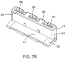
- FIG. 7B is a bottom perspective view of the inner housing 14. Shown in FIG. 7B is a bottom end portion 85 of the inner housing 14, the bottom end portion 85 having slots 88, 89, 90 passing therethrough. A front extending member 87 of the inner housing 14 is similarly shown in FIG. 7B as having a bottom surface 92 thereof.
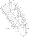
- FIG. 8 shows yet another top perspective view of the inner housing 14 illustrating a front portion 101 and the top portion 72 thereof.
- the front portion 101 of the inner housing 14 is opposite the back portion 70 of the inner housing 14 shown in FIG. 7A .
- Each of the flexible members 75, 76, 77 has an inclined ledge 103.
- Extending from the back portion 70 are the first portion 80, the second portion 82, and the third portion 84 (see, also, FIG. 7A ).
- Each second portion 82 extends at an incline relative to the substantially flat and substantially horizontal first portion 80.
- the top portion 72 of the inner housing 14 is preferably similarly flat and horizontal.
- a substantially concave portion or indentation portion 105 Between the second portion 82 and the third portion 84 is a substantially concave portion or indentation portion 105.
- Upper slots 188, 189, 190 are also shown in FIG. 8 , the upper slots 188, 189, 190 communicating with the lower slots 88, 89, 90, respectively, of the inner housing 14 as shown in FIG. 7B .
- FIG. 9 shows an exploded perspective view of the cable reinforcement retainer assembly 108 (also referred to as reference number 16 in FIG. 1 ), each cable reinforcement retainer assembly 108 having a clamp (or retainer) 105 mounted onto and surrounding a preferably flexible (although not limited thereto) end terminal 107.
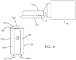
- the end terminal 107 has a substantially flat and substantially bent end portion 110, which attaches to a cable terminal 113 attached to a cable 18.
- the terminal 107 includes a first side portion 115 and a second side portion 117.
- the first side portion 115 includes a plurality of preferably flexible fingers 119
- the second side portion 117 also includes a plurality of preferably flexible fingers 121.
- the flexible fingers 119 and the flexible fingers 121 are substantially symmetrical.
- Attached to the second side portion 117 is at least an extending member 120 that extends towards the first side portion 115.
- Each of the first side portion 115 and the second side portion 117 of the end terminal 107 includes at least an indentation or aperture 122, 123, respectively.
- the clamp (or retainer) 105 of the cable reinforcement retainer assembly 108 includes a first side portion 125 and a second side portion 127.
- Each of the first side portion 125 and the second side portion 127 of the clamp 105 includes at least an inwardly protruding member 130, 132, respectively.
- the protruding members 130, 132 enter the indentations or apertures 122, 123, respectively, when the end terminal 107 is accommodated within the clamp 105 during assembly thereof.
- FIG. 9 is at least a flexible member 133 in the second side portion 127 of the clamp 105.
- the flexible member 133 is shown in FIG. 9 as a pair of flexible members 133, it is not limited thereto.
- At least a side portion 134 of the terminal 107 is prevented from traversing pass at least an inwardly protruding member 136 located at a side 137 of the clamp 105. It is preferred that each of the opposing sides 137 of the clamp 105 includes an inwardly protruding member 136, and that the end terminal 107 includes opposing sides 134.
- the cable reinforcement retainer assembly 108 is shown in FIG. 10 as being fully assembled and the end portion 110 of the end terminal 107 of the clamp 105 being coupled to the terminal 113 of the cable 18.
- the cable reinforcement retainer assembly 108 shows the end portion of at least one of the flexible members 121 of the second side portion 117 of the end terminal 107, and an end portion of at least one of the flexible members 119 of the first side portion 115 of the end terminal 107. See, also, FIG. 9 .
- FIG. 11A is an elevational view of the second side portion 117 of the end terminal 107 and the second side portion 127 of the clamp 105 of the cable reinforcement retainer assembly 108.
- the second side portion 127 of the clamp 105 includes at least a flexible member 133.
- shown in FIG. 11A is a pair of flexible members 133 with an elongated slit 138 therebetween.
- the inwardly protruding members 130 in the second side portion 127 of the clamp 105 which are preferably inclined for easy entry into the indentations or apertures 122 of the end terminal 107 (see, FIG. 9 ) when the end terminal 107 is moved inside the clamp 105.
- the end terminal 107 is held inside the clamp 105. That is, the inwardly protruding members 130, 132 of the clamp 105 are preferably inclined for allowing the terminal 107 to be inserted into the clamp 105; and once the inwardly protruding members 130, 132 have been respectively accommodated within the indentations or apertures 122, 123 of the end terminal 107, the terminal 107 is prevented from being pulled out from the clamp 105. As described earlier with respect to FIG.
- the opposing sides134 of the end terminal 107 are held by the inwardly protruding members 136 of the clamp 105, and prevents the retainer 107 from being pushed further forward into the clamp 105.
- the cable retainer assembly 108 as illustrated in FIGS. 10 , 11A , and 11B , has the ends of the flexible members 119, 121 of the terminal 107 extending outside of the clamp 105.
- FIG. 11B Illustrated in FIG. 11B is an elevational view of the cable retainer assembly 108 showing the first side portion 115 of the end terminal 107 and the first side portion 125 of the clamp 105. Illustrated here are the inwardly protruding members 132 and the pair of flexible members 135 of the clamp 105, and the ends of the flexible members 119 of the first side portion 115 of the terminal 107 extending outside of the clamp 105 when the cable reinforcement retainer assembly 108 is assembled as shown.
- FIG. 11B Further shown in FIG. 11B is an elongated slit 140 (shown here as passing in its entirety through the first side portion 125 of the clamp 105 between the pair of flexible members 135.
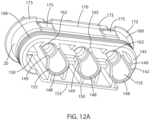
- FIG. 12A illustrates a perspective view of a bottom portion 142 and a back portion 145 of the back cover 20. Shown here is at least a substantially half-circular tubular member 148 having a bottom portion 149 and extending from the back portion 145 of the back cover 20. For strength and stability, the half-circular tubular members 148 are joined to bridge (or rib) members 150 respectively connected to the back cover 20 and extending to the sides 153 of the back cover 20. Openings 155 of the tubular members 148 extend toward a middle portion 160 of the back cover 20. Inside the middle portion 160 are substantially circular apertures 162, which respectively communicate with the tubular members 148.
- a circular fitting silicone seal 165 Inside each of the circular apertures 162 is a circular fitting silicone seal 165; and on the outer periphery of the middle portion 160 of the back cover 20 is an over-molded silicone seal 168.
- the back cover 20 has the circular fitting silicone seal 165 for interface with the cable 18 and the over-molded silicone seal 168 for interface with the inner surface of the outer housing 5.
- the back cover 20 acts as a terminal position assurance (TPA) device for the high voltage connector 1 of this invention.
- TPA terminal position assurance
- Surrounding a lower portion 170 of the back cover 20 Surrounding a lower portion 170 of the back cover 20 are ledges 173; and between the ledges 173 are inclined protruding members 175, as shown in FIG. 12A .
- FIG. 12A The above-described elements of the back cover 20, as shown in FIG. 12A , are similarly shown in the elevational view of the back portion 145 of the back cover 10 illustrated in FIG. 12B .
- Shown here are the tubular members 148, and bridge (rib) members 150 connected to the sides 153.
- FIG. 12B Also shown in FIG. 12B are the respective openings 155 of the tubular members 148, which communicate with the circular apertures 162 thereof, the respective circular fitting silicone seals 165 being fitted inside the circular apertures 162, and the silicone seal 168 surrounding the outer periphery of the middle portion 160 of the back cover 20.
- Shown in FIG. 12B are the ledges 173 surrounding, on all sides, the lower portion 170 (see, FIG. 12A ) of the back cover 20, and the inclined protruding members 175 extending on opposing sides of the back cover 20, as shown in FIG. 12B .
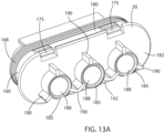
- FIG. 13A is a perspective view of a top portion 180 and a front portion 182 of the back cover 20. Shown on the top portion 180 are the inclined protruding members 175. Opposite the top portion 180 of the back cover 20 is the bottom portion 142 thereof. Extending from the front portion 182 are top tubular members 185 with respective openings 188 that respectively communicate with the circular apertures 162 extending through the middle portion 160 of the back cover. As in the half-circular tubular members 148 extending from the back portion 145, the top tubular members 185 are similarly surrounded by bridge (or rib) members 190. Surrounding the outer periphery of the middle portion 160 is the silicone seal 168.
- FIG. 13B is an elevational view of the front portion 182 of the back cover 20 showing the respective openings 188 of the top tubular members 185 and the associated bridge (or rib) members 190. Also shown in FIG. 13B are the respective circular fitting silicone seals 165, discussed earlier with respect to FIG. 13A , and the inclined protruding members 175 located in the front portion 182 at opposing sides thereof.
- FIG. 14A is a perspective view of the braided shield 22 having an internal opening 192 extending along the entire length thereof.
- the braided shield 22 is made of metal, preferably stainless steel or the like.
- FIG. 14B is a perspective view of the metallic clamp 25, which is substantially ring-like in shape and is made of stainless steel or the like.
- the ground system is provided with the connection of the connector 1 to the associated aluminum device 210 by establishing contacts among the metal-infused conductive plastic outer housing 5, the aluminum compression limiters 28, the stainless steel bolts 12, and the associated aluminum device 210.
- the substantial reduction or elimination of EMI is provided by the metal-infused pads 48 of the outer housing 5 in conjunction with the braided shield 22 extending along the paths of the cables 18, the metal-infused pads 48 contacting the associated aluminum device 210.
- This invention further provides a galvanic corrosion prevention with the base 52 of the non-conducting over-molded silicone seal 7 shielding the metal-infused conductive plastic outer housing 5 and the associated aluminum device 210 from electrolytic fluid to prevent galvanic corrosion.
- Galvanic corrosion is further prevented with the side members 57 of the upper portion 55 of the silicone seal 7 shielding the metal-infused conductive plastic outer housing 5 and the aluminum compression limiters 28, and further shielding the stainless bolts 12 and the associated aluminum device 210 from electrolytic fluid to prevent galvanic corrosion.
- the method for assembling the high voltage connector of this invention is hereinafter described in detail.
- the bolts 12 are respectively secured into the compression limiters 28, which are inside the side apertures 38 of the outer housing 5, thereafter mounting the outer housing 5, along with the outer-molded silicone seal 7, onto the device 210 (see, FIG. 15 ) onto which the outer housing 5 and subsequently the connector 1 is to be mounted.
- the bolts 12 securely fasten the connector 1 to the device 210, and provides grounding among the braided shield 22, the outer housing 5, and the device 210.
- the stainless steel bolts 12 and the aluminum compression limiters 28 provide the contact between the connector 1 and the device 210 to ground the system.
- the inner housing 14 is then inserted or slid into the central opening 40 of the outer housing 5 until the inner housing 14 is about to reach or reaches the end portion 45 (see, FIG. 6 ) of the outer housing 5, and the inner housing 14 is then inserted or slid downward into the bottom opening or aperture 50 (see, FIG. 6 ) of the outer housing 5 so as to mount the inner housing 14 onto the base 32 of the outer housing 5 until a clicking sound or the like is heard, which assures that the inner housing 14 is secured inside the outer housing 5.
- the over-molded silicone seal 7 provides a sealing and insulation layer for galvanic corrosion protection between the connector 1 and the device 210.
- a plurality of pre-assembled cable reinforcement retainer assemblies 108 with their respective cables 18 is first inserted into the central opening 40 of the outer housing 5 and then inserted downward into the inner housing 14 until a clicking sound or the like is heard in which case the back cover 20 then slides along the cables 18 through the central opening 40 and into the outer housing 5 until a clicking sound or the like is again heard once the back cover 20 is secured inside the outer housing 5.
- the partially assembled connector 1 is as shown in FIG. 2A .
- the braided shield 22 is mounted onto the outer housing 5, and the clamp 25 is slid down over the braided shield 22 towards the back end portion of the braided shield 22 and rests thereonto (see, FIG. 2B ) and provides the conductive contact between the braided shield 22 and the outer housing 5.
- the inner housing 14 when the inner housing 14 is inserted into the central opening 40 of the outer housing 5, the inner housing 14 is about to reach or reaches the end portion 45 of the outer housing 5 and is then inserted into the opening or aperture 50 and lowered towards the base 32 of the outer housing 5, the downwardly extending member 83 of the inner housing 14 enters (or slides) downwards into the bottom opening or aperture 50 of the outer housing 5. Then, the bottom surface 92 of the front extending member 87 of the inner housing 14 mounts onto an inner side portion 41 (see, FIGS. 3A and 6 ) of the outer housing 5. Substantially thereupon, the upper portion 201 of the flexible latch member 200 (see, FIG. 8 ) on opposing sides of the inner housing 14 respectively enter indentations 99 (see, FIG.
- the inner housing 14 (preferably made of nylon or the like) provides separation between conductive parts (e.g., the outer housing 5 made of metal-infused plastic or the like and the cable terminals 107 secured inside the inner housing 14).
- the preferably pre-assembled cable reinforcement retainer assemblies 108 are then inserted or slid into the central opening 40 of the outer housing 5 and lowered towards the upper slots 188, 189, 190 (see, FIG. 8 ) of the inner housing 14. More particularly, with the second side portions 125 of the clamps 105 respectively facing the front portion 70 of the inner housing 14, the cable reinforcement retainer assemblies 108 are inserted or slid substantially horizontally through the central opening 40 of the outer housing 5 and subsequently lowered respectively through the upper slots 188, 189,190, but do not pass beyond the slots 88, 89, 90 of the bottom end portions 85 of the inner housing 14 (see, FIG. 7B ).
- the cable reinforcement retainer assemblies 108 respectively travel downward through the upper slots 188, 189, 190 of the inner housing 14 and the clamps 105 respectively push, while traveling downward, the inclined ledges 103 of the flexible members 75, 76, 77 (see, FIG. 8 ) of the inner housing 14 until each upper end 128 (see, FIG. 10 ) of each clamp 105 respectively settles beneath one of the inclined ledge 103 of the inner housing 14 (see, FIG. 8 ); thereupon, a clicking sound or the like is heard, which indicates that the clamps 105 and consequently the cable reinforcement retainer assemblies 108 are securely fastened within the inner housing 14. At this time, the substantially flat and substantially bent portion 110 (see, FIG.
- the end terminal 107 sits or is mounted onto the substantially flat and substantially horizontal first portion 80 of the front extending member 87 of the inner housing 14.
- the second portions 82 of the front extending member 87 of the inner housing 14 respectively separating the substantially flat and substantially bent portions 110 of the end terminals 107.
- the back cover 20 is slid substantially horizontally, along the cables 18, towards the outer housing 5 and through the central opening 40 thereof until the inclined protruding members 175 (see, FIGS. 13A and 13B ) at opposing sides of the back cover 20 respectively enter the apertures 42 (see, FIGS. 3A and 3B ) passing through the front portion of the outer housing 5 at which time a clicking sound or the like is heard to indicate that the back cover 20 has been securely fastened to the outer housing 5 with the cable reinforcement retainer assemblies 108 similarly fully secured inside the outer housing 5. That is, the back cover 20 pushes the inner housing 14 in place and ensures that the inner housing 14 is properly positioned in the outer housing 5.
- the horizontal high voltage connector 1 of this invention is mounted onto a device 210 (e.g., an inverter or the like) with the use of the bolts 12.
- the downwardly extending member 83 of the inner housing 14 is shown as having passed through the bottom opening or aperture 50 of the bottom end portion 45 of the base 32 of the outer housing 5 and through the over-molded silicone seal 7.
- the pads 48 of the bottom end portion 45 of the base 32 of the outer housing 5 are shown as being inside the elongated slots 51 of the over-molded silicone seal 7.
- the substantially flat and substantially bent portion 110 (see, FIG. 10 ) of the end terminal 107 of the cable reinforcement retainer assembly 108 sits or is mounted onto the substantially flat and substantially horizontal first portion 80 of the front extending member 87 of the inner housing 14.
- the bottom surface 92 of the front extending member 87 of the inner housing 14 is seated or mounted onto an inner side portion 41 (see, FIGS. 3B and 6 ) of the outer housing 5.
- FIG. 15 Also illustrated in FIG. 15 is the wedge or impinging mechanism A for securing the cables 18 in the inner housing 14. More particularly, when the back cover 20 is inserted or slid substantially horizontally, along the cables 18, through the central opening 40 and into the outer housing 5, the bottom portions 149 of the substantially half-circular tubular members 148 (see, FIG. 12A ) of the back cover 20 respectively wedge or impinge against top face portions 111 (see, FIGS. 10 and 11A ) of the end portions 110 of the end terminals 107 of the cable reinforcement retainer assemblies 108, thereby securing the cables 18 inside the inner housing 14. As shown in FIG. 16 , the ends of the flexible members 119, 121 of the terminal 107 (see, e.g., FIG. 10 ), which extend to the outside of the clamp 105, connect with a set of terminals 220 of the associated device 210.
- the braided shield 22 is slid substantially horizontally towards the outer housing assembly 3 whereby a back portion of the braided shield 22 passes the outer ledges 98a, 98b (see, FIG. 6 ), extend from a portion of the outer housing 3 near its central opening 40.
- the clamp 25 is then slid substantially horizontally along the braided shield 22 pass the outer ledges 98a, 98b, and at about pass the outer ledges 98a, 98b, the clamp 25 connects the braided shield 22 to the outer housing 5 and assures the connection thereof.
- the horizontal high voltage connector 1 of this invention When fully-assembled, the horizontal high voltage connector 1 of this invention includes a ground system that is provided with the connection of the connector 1 to the associated aluminum device 210 by establishing contacts among the metal-infused conductive plastic outer housing 5, the aluminum compression limiters 28, the stainless steel bolts 12, and the associated aluminum device 210.
- the substantial reduction or substantial elimination of EMI is provided by the shielding of the EMI by the braided shield 22 extending along the paths of the cables 18, or the diversion of the EMI from the braided shield 22 to the metal-infused pads 48, which are used for EMI grounding, contacting the associated aluminum device 210.
- the EMI is diverted to a path from the stainless steel braided shield 22, which is connected to the metal-infused plastic outer housing 5 by the stainless steel clamp 25, to the metal-infused plastic outer housing 5 mounted onto the, for example, aluminum inverter 210.
- This invention further provides a galvanic corrosion prevention with the base 52 of the non-conducting over-molded silicone seal 7 shielding the metal-infused conductive plastic outer housing 5 and the associated aluminum inverter 210 from electrolytic fluid to prevent galvanic corrosion.
- the metal-infused pads 48 protruding through and bordered by the silicone seal 7 prevents galvanic corrosion between the metal-infused outer housing 5 and the aluminum inverter 210.
- Galvanic corrosion is further prevented with the side members 57 of the upper portion 55 of the silicone seal 7 shielding the metal-infused conductive plastic outer housing 5 and the aluminum compression limiters 28, and further shielding the stainless bolts 12 and the associated aluminum inverter 210 from electrolytic fluid to prevent galvanic corrosion.
- FIG. 17 is the fully assembled vertical high voltage connector assembly 1 of this invention showing electrical grounding paths 220, 230, 240, 250 of the EMI noise generated by a source (e.g., the conducting high voltage cables 18, the conducting cable reinforcement retainer assemblies 16, 108, the battery itself, or the like, or any other source), which is then conducted through the metallic braided shield 22, flowing through the high voltage connector 1, and conducted ultimately to the corresponding metallic device 210 onto which the high voltage connector 1 is mounted.
- FIG. 18 is a corresponding flowchart of the electrical grounding paths 220, 230, 240, 250 of the EMI noise that flows through the metallic braided shield 22, flowing through the high voltage connector 1, and conducted ultimately to the corresponding metallic device 210 onto which the high voltage connector 1 is mounted.
- the EMI noise when the EMI noise is generated by, for example, the vehicle high voltage battery, the conducting cables 18 connected to the battery, the cable reinforcement assemblies 16, 108, or the like, or any other source, the EMI noise, for reasons discussed earlier, needs to be reduced, suppressed, or eliminated.
- the electrical grounding EMI noise flow paths 220, 230, 240, 250 are illustrated in FIG. 17 .
- the EMI noise flow path 220 initially flows through the metallic braided shield 22 (made of stainless steel or the like).
- the EMI noise flow path 220 then flows through the metallic clamp 25, which (as discussed earlier) secures the metallic braided shield 22 to the multi-directional conductive outer housing 5.
- the outer housing 5 is made of a metal-infused conductive plastic, resin, nylon, or the like.
- the outer housing 5 may also be made of a stainless steel fiber-filled plastic, resin, nylon, or the like.
- the EMI noise flow path 220 is then directed to the EMI noise flow path 230 along an angled or multi-directional portion of the conductive outer housing 5, which travels through a different direction from the EMI noise flow path 220.
- the EMI flow path which similarly travels along the conductive outer housing 5, is orthogonal to the direction through which the EMI noise flow path 220 travels.
- the EMI noise flow path 230 continues its travel through the EMI noise flow path 240, and is then conducted to at least one of the metallic compression limiters 28 (made of aluminum or the like) that surrounds a corresponding bolt (made of stainless steel or the like).
- the EMI noise flow path 240 flows to the metallic compression limiter 28 (made of aluminum or the like) (see EMI noise flow path 240 in FIG. 17 ), the metallic compression limiter 28 surrounding a corresponding bolt 12 (made of stainless steel or the like), the bolt 12 connecting the connector assembly 1 to the metallic device 210 onto which the connector assembly 1 is mounted.
- the EMI noise flow path 240 thereby travels from the conductive outer housing 5 to the metallic compression limiter 28 to the surrounding corresponding stainless steel bolt 12, and is ultimately conducted to the associated metallic device 210.
- the associated metallic device 210 may be, e.g., an aluminum automotive transmission.
- FIG. 5A illustrates the bottom end portion 45 of the outer housing assembly 3 with the pads 48 of the outer housing 5 passing through the elongated slits 51 of the silicone seal 7 when the outer housing 5 sits and mounts onto the over-molded silicone seal 7.
- FIG. 5B illustrates the bottom end portion 45 of the outer housing assembly 3 with the pads 48 of a different embodiment or pattern passing through corresponding elongated slits 51 of a different embodiment or pattern of the silicone seal 7 when the outer housing 5 sits and mounts onto the over-molded silicone seal 7.
- the tightening of the bolts 12 in connecting the connector assembly 1 to the corresponding metallic device 210 ensures that physical contact is maintained between the pads 48 of the conductive outer housing 5 and the corresponding metallic device 210, although the tightening of the bolts 12 is limited by the compression limiters 28 to ensure that the physical or functional integrity of the silicone seal 7 is maintained.
- the EMI noise flow path 220 flows from the metallic braided shield 22 to the multi-directional conductive outer housing 5 following the EMI noise flow path 230 along an angled or orthogonally directed part of the multi-directional conductive outer housing 5 directly to the corresponding metallic device 210 (see, EMI noise flow path 250).
- the EMI noise flow path 240 can travel to the plurality of metallic compression limiters 28 and to the corresponding stainless steel bolts 12 shown in FIGS. 2A and 2B .
- the EMI noise flow path 250 can travel through the plurality of pads 48 of the conductive outer housing 5 of differing embodiments or patterns passing through corresponding elongated slits 51 of differing embodiments or patterns of the silicone seal 7, as discussed above with respect to FIGS. 5A and 5B .
- the noise flow path 220 of the generated EMI noise flows from the metallic braided shield 22 and ultimately to the corresponding metallic device 210 as follows: (1) from the metallic braided shield 22 to the multi-directional conductive outer housing 5 through the metallic compression limiters 28 and through their respective bolts 12 and ultimately to the corresponding metallic device 210 (see, the EMI noise flow paths 220, 230, 240), and (2) from the metallic braided shield 22 to the multi-directional conductive outer housing 5 through the conductive pads 48 thereof and ultimately to the corresponding metallic device 210 (see, EMI noise flow paths 220, 230, 250).
- FIG. 17 shows an angled or orthogonally directed part of the conductive outer housing 5 through which the EMI noise flow path 230 is directed
- multi-directional parts of the conductive outer housing 5 are surely envisioned by the inventor and is, alternatively, paths through which the EMI noise flow paths 220, 230, 240, 240 may be directed.
- FIG. 18 further illustrates the EMI noise flow paths 220, 230, 240, 250 flowing from the metallic braided shield 22 and ultimately to the corresponding metallic device 210.
- the EMI noise is, as discussed above, generated by a source (e.g., a battery of an electric vehicle, a hybrid vehicle, or the like, or conducting cables 18, or conducting cable reinforcement retainer assemblies 16, 108, or the like), and the method for protecting the connector assembly 1 from the EMI grounding noise is shown in the flowchart of FIG. 18 .
- a source e.g., a battery of an electric vehicle, a hybrid vehicle, or the like, or conducting cables 18, or conducting cable reinforcement retainer assemblies 16, 108, or the like
- Step 1 (S1) the EMI noise is conducted through the metallic braided shield 22.
- Step 2 (S2) the EMI noise continues its flow through noise flow path 220 to the metallic clamp 25, and continues further through the EMI noise flow path 220 to the multi-directional conductive outer housing 5 through an angled part or multi-directional part of the conductive outer housing 5 in EMI noise flow path 230 in Step 3 (S3).
- the EMI noise is conducted, in Step 4A (S4A), from the angled part or the multi-directional part of the conductive outer housing 5 to the metallic compression limiters 28 continuing through the EMI noise flow path 240 to the corresponding bolts 12 in Step 5A (S5A), and conducted ultimately in Step 6A (S6A) to the metallic device 210 onto which the connector assembly 1 is mounted.
- the EMI noise is conducted, in Step 4B (S4B), from the angled part or the multi-directional part of the conductive outer housing 5 directly through the conductive pads 48 of the conductive outer housing 5 and conducted ultimately to the corresponding metallic device 210 in Step 5B (S5B) onto which the connector assembly 1 is mounted.
Abstract
An electromagnetic interference (EMI) grounding protection method for a connector assembly using a multi-directional conductive housing. The method includes the steps of: conducting the EMI generated by a source towards a metallic braided shield, the metallic braided shield being secured and mounted onto the multi-directional conductive housing by a metallic clamp; conducting the EMI from the metallic braided shield to the metallic clamp and to the multi-directional conductive housing, the multi-directional conductive housing being mounted onto a metallic device by at least a metallic bolt and the bolt being accommodated within a corresponding metallic compression limiter; and thereafter, conducting the EMI: (1) from the metallic braided shield to the multi-directional conductive housing through the metallic compression limiters and through their respective bolts, and ultimately to the metallic device, and (2) from the metallic braided shield to the multi-directional conductive housing directly through conductive pads thereof, and ultimately to the metallic device.
Description
- It is desired that a high voltage connector assembly connected to a device be provided. It is further desired that the high voltage connector assembly experiences a reduced or suppressed electromagnetic interference (EMI) through conductive seals and a multi-directional conductive housing.
- This invention provides such a high voltage connector for connecting to a device which, when in operation, experiences reduced or suppressed EMI. This is achieved by providing the connector with a metallic braided shield on top of an inverter outer housing assembly or the like. The connector in this invention is further provided with a metallic clamp that holds the metallic braided shield above a multi-directional conductive outer housing, and provides a conductive contact between the metallic braided shield and the multi-directional conductive outer housing. The multi-directional conductive outer housing, which is made of a metal-infused plastic, resin, nylon, or the like, includes an over-molded silicone seal to provide the necessary sealing and insulation layer to prevent galvanic corrosion between the connector and the device to which the connector is connected. The outer housing may also be made of a stainless steel fiber-filled plastic, resin, nylon, or the like. The metal-infused or stainless steel fiber-filled outer housing with the over-molded silicone shield includes apertures through which bolts pass through for fastening the connector of the invention to the device. The bolts provide the necessary grounding among the metallic braided shield, metal-infused plastic outer housing, and the device to which the connector of this invention is to be connected. Each bolt is preferably inserted into a corresponding metallic compression limiter within a respective one of the apertures of the outer housing. A ground system is provided to the connector of this invention by establishing a contact between the connector and the device, with the connection of the connector to the device, by the bolts and the metallic compression limiters. Moreover, the steel bolts are contained within the metallic compression limiters, which are in turn contained within side apertures of the outer housing. On the outer periphery of the base of the metal-infused outer housing is an over-molded silicone seal, which, along with the above-described structural arrangement composed of dissimilar metals, provides for corrosive resistant characteristics.
- The connector of this invention further includes an inner housing provided within the outer housing, the inner housing further having cable reinforcement retainer assemblies securely inserted therein. The inner housing accommodates therein the cables that are directed to a desired direction in conjunction with the conductive outer housing having angled parts or multi-directional parts.
- The connector of this invention further includes a back cover, which acts as a terminal position assurance (TPA) device, through which cables slide and secured thereinto, during the assembly of the connector. The back cover includes over-molded silicone seals for isolating the connecting interface of the cables. During assembly of the connector, the back cover ensures that the inner housing is properly positioned within the outer housing. The outer housing is inclined (i.e., a part thereof extending in one direction, while another part extends in another direction) so as to accommodate therein the cables extending to any direction. In this case, the outer housing has a part extending in one direction, and another part extending in another direction, the two directions being orthogonal to each other, although the shape of the outer housing is not limited thereto.
- Generally, upon assembly of the connector of this invention, an inverter outer housing assembly, having the metal-infused plastic outer housing with the over-molded silicone seal, is mounted onto the associated device with the bolts accommodated within the respective metallic compression limiters; the inner housing is seated inside and onto the base of the outer housing; the back cover with its associated cables and cable reinforcement retainer assemblies are mounted inside the angled outer housing and onto the inner housing with the cables being slid upwards through the back cover; the metallic braided shield is mounted onto the outer housing while covering the exposed cable; and the clamp is slid along the braided shield to secure thereof onto the outer housing.
- In, for example, an electric vehicle or a hybrid vehicle, EMI is a noise generated by, e.g., a high voltage source (such as, a battery or a set of conducting high voltage cables connected to the battery). Electrical shielding becomes important in reducing, suppressing, or eliminating EMI noise between components within the vehicle so as to avoid any loss of any or all of vehicle function. Proper grounding of all the shielding components is important to suppress, reduce, or remove all EMI noise from the system. This invention uses, for example, conductive housing (made of a metal-infused conductive plastic, resin, nylon, or the like, or made of a stainless steel fiber-filled plastic, resin, nylon, or the like), metallic compression limiters, metallic clamp, metallic braided shield, and metallic bolts to ground the connector assembly of this invention and suppress, reduce, or eliminate EMI noise. The EMI electric noise, generated by the, for example, vehicle battery flows through the metallic braided shield then conducted to the metallic clamp to the conductive housing, which includes parts that are angled relative to each other, to the metallic compression limiters to the metallic bolts, and then to the associated metallic device onto which the connector assembly is mounted. Alternatively, the EMI electric noise, generated by the, for example, vehicle battery or the conducting cables that are connected thereto flows through the metallic braided shield then conducted to the metallic clamp to the multi-directional conductive housing, which includes parts that are angled relative to each other, and then directly to the associated metallic device onto which the connector assembly is mounted.
-
-
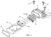
FIG. 1 is an exploded view of the high voltage connector of this invention, generally referred to byreference number 1, showing the different elements thereof arranged in the horizontal direction ready to be mounted onto an associated device. -
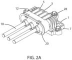
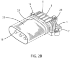
FIG. 2A is a perspective view of a fully assembled connector of this invention, absent the braided shield, with the cables exposed; andFIG. 2B is a perspective view of the fully assembled connector of this invention showing the braided shield fully secured to the outer housing with the metallic clamp. -
FIG. 3A is a top perspective view of the outer housing, whileFIG. 3B is a bottom perspective view of the outer housing. -
FIG. 4A is a top perspective view of the outer housing surrounded on a bottom periphery thereof with a corresponding over-molded silicone seal; andFIG. 4B is an exploded view of the outer housing and the corresponding over-molded silicone seal with the compression limiters that fit within coincident apertures of the outer housing and the silicone seal. -
FIG. 5A is a bottom elevational view of a base end portion of the outer housing assembly showing a pad of the outer housing passing through elongated slits of a base of the over-molded silicone seal; andFIG. 5B is a bottom elevational view of the base end portion of the outer housing assembly showing another embodiment or pattern of the pad of the outer housing passing through another embodiment or pattern of the corresponding elongated slits of the base of the over-molded silicone seal. -
FIG. 6 is a front perspective view of the outer housing showing the inner surface thereof through a central opening thereof. -
FIG. 7A is a top perspective view of an inner housing showing a back portion and a top portion thereof, whileFIG. 7B is a bottom perspective view of the inner housing. -
FIG. 8 shows yet another top perspective view of the inner housing illustrating a front portion and the top portion thereof. -
FIG. 9 shows an exploded perspective view of a cable reinforcement retainer assembly, the cable reinforcement retainer assembly having a clamp (or retainer) mounted onto and surrounding an end terminal. -
FIG. 10 illustrates a side elevational view of the cable retainer assembly as being fully assembled and an end portion of the end terminal of the clamp being coupled to a terminal of a cable. -
FIG. 11A is an elevational view of a first side portion of the end terminal and a first side portion of the clamp of the cable reinforcement retainer assembly, whileFIG. 11B is an elevational view of a second side portion of the end terminal and a second side portion of the clamp of the cable retainer assembly. -
FIG. 12A illustrates a perspective view of a bottom portion and a back portion of a back cover, whileFIG. 12B illustrates an elevational view of the back portion of the back cover. -
FIG. 13A is a perspective view of a top portion and a front portion of the back cover; whileFIG. 13B is an elevational view of the front portion of the back cover. -
FIG. 14A is a perspective view of the braided shield; andFIG. 14B is a perspective view of the metallic clamp. -
FIG. 15 is the fully assembled horizontal high voltage connector of this invention showing a wedge (or impinging) mechanism for securing the cables in the inner housing contained within the outer housing. -
FIG. 16 is the fully assembled horizontal high voltage connector of this invention showing the wedge (or impinging) mechanism for securing the cables in the inner housing contained within the outer housing, and further showing a terminal extending from a corresponding device, onto which the connector is mounted, to connect with an end terminal of the cable reinforcement retainer assembly. -
FIG. 17 is the fully assembled multi-directional, angled, or horizontal high voltage connector of this invention showing an electrical grounding path of the EMI noise generated by a source, which is then conducted through the metallic braided shield, flowing through the connector assembly, and conducted ultimately to the corresponding metallic device onto which the connector assembly is mounted. -
FIG. 18 is a flowchart of the electrical grounding path of the EMI noise that flows through the metallic braided shield, flowing through the multi-directional, angled, or horizontal connector assembly, and conducted ultimately to the corresponding metallic device onto which the connector assembly is mounted. - As illustrated in
FIG. 1 , thehigh voltage connector 1 includes anouter housing assembly 3, which includes an angled, multi-directional, or horizontal conductiveouter housing 5 with an accompanyingover-molded silicone seal 7. In this case, the multi-directional conductiveouter housing 5 includes a part that extends vertically and another part that extends in the horizontal direction orthogonal to the vertically extending part, although the multi-directional conductiveouter housing 5 of this invention is not limited thereto. The multi-direction conductiveouter housing 5 is preferably made of a metal-infused housing, and includesside extending portions 62 of abase 32 thereof for accommodating therein respective bolts 12 (made of stainless steel or the like) for fastening theconnector 1 to an associated device 210 (see,FIG. 15 ; e.g., an inverter or the like made of, e.g., aluminum). - Accommodated within the
outer housing 5 and mounted onto thebase 32 thereof is aninner housing 14. Theconnector 1 further includes a set of cable reinforcement retainer assemblies 16 (specifically referred to asreference number 108 inFIGS. 9 ,10 ,11A , and11B ) for coupling with theinner housing 14 and a set ofcables 18. The set ofcables 18 is preferably high voltage cables (e.g., 25 mm2 cables), although the type of cables is not limited thereto. Although shown inFIG. 1 is a set of 3-way high voltage cables, this embodiment is also not limited thereto. Thecables 18 are slidably accommodated within aback cover 20. Theconnector 1 further includes a metallic (e.g., stainless steel) braidedshield 22, which forms the outer layer of theconnector 1, when theconnector 1 is fully assembled, as shown inFIG. 2B . Ametallic clamp 25 secures the braidedshield 22 onto theouter housing 5, when theconnector 1 is fully assembled, as also shown inFIG. 2B . -
FIG. 2A illustrates theconnector 1 when fully assembled absent the braidedshield 22, whileFIG. 2B illustrates theconnector 1 when fully assembled with thebraided shield 22 secured onto theouter housing 5 by themetallic clamp 25. Further shown inFIG. 2A is theouter housing assembly 3 with theouter housing 5 that securely sits onto and within the outer-moldedsilicone seal 7 through which thebolts 12 are fastened with respectivemetallic compression limiters 28, which are made of aluminum or the like. As later discussed, the set ofcables 18 extend through an upper portion 30 of theouter housing 5. - In
FIG. 2B , covered by themetallic braided shield 22 are the set ofcables 18. Themetallic clamp 25 ensures that the bottom portion 33 of themetallic braided shield 22 is connected to the upper portion 30 of theouter housing 5. - Extending in the horizontal direction, as illustrated in
FIG. 3A , is theouter housing 5 having the base 32 withhorizontal ribs 34 extending from a side of the base 32 towards acentral portion 36 of theouter housing 5. Also shown inFIG. 3A , with respect to theouter housing 5 and as discussed earlier, are the extending side portions orribs 9 andside apertures 38 for accommodating therein, along with thesilicone seal 7, therespective bolts 12 and the respectivemetallic compression limiters 28. Theouter housing 5 is preferably made of a metal-infused plastic, while thebolts 12 are preferably made of stainless steel or the like. - Passing through the
central portion 36 of theouter housing 5 is acentral opening 40 for accommodating therein, in full, theinner housing 14 and the cable reinforcement retainer assembly 16, and for further accommodating therein, in part, the set ofcables 18.Apertures 42 pass through an upper portion of theouter housing 5. - Illustrated in
FIG. 3B is thebottom end portion 45 of theouter housing 5. Thebottom end portion 45 is substantially flat and includes at least apad 48 extending therefrom. Thepad 48 surrounds a bottom opening oraperture 50 passing through thebottom end portion 45 of thebase 32 of theouter housing 5. When theouter housing 5 is mounted onto an associated device 210 (see,FIG. 15 ), thepad 48 provides the necessary means for substantially reducing or substantially deleting any occurrence of EMI. The bottom opening oraperture 50 is preferably smaller in size than thecentral aperture 40 of theouter housing 5, and communicates therewith. -
FIG. 4A shows theouter housing assembly 3, which comprises theouter housing 5 and theover-molded silicone seal 7, thebase 32 of theouter housing 5 sitting onto and within theover-molded silicone seal 7. Theover-molded silicone seal 7 provides a sealing and insulation layer for galvanic corrosion protection between theconnector 1 and thedevice 210. - In
FIG. 4B , illustrated is an exploded view of theouter housing assembly 3 showing theouter housing 5 and its correspondingover-molded silicone seal 7. As described earlier with respect to theouter housing 5 shown inFIGS. 3A and3B , theouter housing 5 includes a base 32 with abottom end portion 45. As also described with respect toFIG. 3B , thebase end portion 45 includes thepad 48, which fits and passes throughelongated slits 51 passing through abase 52 of the over-molded silicone seal 7 (see,FIG. 4B ). As further described with respect toFIG. 3B , the substantially flatbottom end portion 45 of theouter housing 5 sits and mounts onto thebase portion 52 of theover-molded silicone seal 7, as shown inFIGS. 4A and4B . In theover-molded silicone seal 7, shown inFIG. 4B , thebase portion 52 includesside apertures 53, while anupper portion 55 of thesilicone seal 7 includesside members 57, each of theside member 57 having anaperture 60 passing therethrough. As shown inFIG. 4A , eachupper portion 55 of thesilicone seal 7 fits onto one of theside extending portions 62 of thebase 32 of theouter housing 5. Thus, eachaperture 60 of each one of theside member 57 of thesilicone seal 7 corresponds to a respective one of theapertures 38 of thebase 32 of theouter housing 5 for respectively accommodating therein themetallic compression limiters 28. -
FIG. 5A illustrates thebottom end portion 45 of theouter housing assembly 3 with thepads 48 of theouter housing 5 passing through theelongated slits 51 of thesilicone seal 7 when theouter housing 5 sits and mounts onto theover-molded silicone seal 7.FIG. 5B illustrates thebottom end portion 45 of theouter housing assembly 3 with thepads 48 of a different embodiment or pattern passing through correspondingelongated slits 51 of a different embodiment or pattern of thesilicone seal 7 when theouter housing 5 sits and mounts onto theover-molded silicone seal 7. -
FIG. 6 is a top perspective view of theouter housing 5 showing the inner surface thereof through acentral opening 40 thereof. As can be seen through thecentral opening 40 of theouter housing 5, as illustrated inFIG. 6 , substantially orthogonal to thecentral opening 40 and communicating therewith is a bottom opening oraperture 50 passing through anend portion 45 substantially orthogonal to thebase 32 of theouter housing 5. As further shown inFIG. 6 , aninner ledge 95 extends from aninner surface 97 of theouter housing 5. Although not shown inFIG. 6 , a similar type ofinner ledge 95 extends from the opposite side of the inner surface of theouter housing 5. Also shown inFIG. 6 areouter ledges outer housing 5. - Next described in detail is the
inner housing 14, which is accommodated within theouter housing 5 and sits onto thebase 32 thereof. Theinner housing 14 is preferably made of nylon or the like. The inner housing 14 (preferably made of nylon or the like) provides separation between conductive parts (e.g., theouter housing 5 made of metal-infused plastic or the like and thecable terminals 107 secured inside the inner housing 14).FIG. 7A is a top perspective view of theinner housing 14 showing aback portion 70 and atop portion 72 thereof. Theback portion 70 of theinner housing 14 hasflexible members top portion 72 of theinner housing 14 has extending therefromfirst portion 80,second portion 82, andthird portion 84. Theinner housing 14 is generally, as shown inFIG. 7A , an upside down (or inverted) substantially L-shaped structure with a downwardly extendingmember 83 and a front extendingmember 87. -
FIG. 7B is a bottom perspective view of theinner housing 14. Shown inFIG. 7B is abottom end portion 85 of theinner housing 14, thebottom end portion 85 havingslots member 87 of theinner housing 14 is similarly shown inFIG. 7B as having abottom surface 92 thereof. -
FIG. 8 shows yet another top perspective view of theinner housing 14 illustrating afront portion 101 and thetop portion 72 thereof. Thefront portion 101 of theinner housing 14 is opposite theback portion 70 of theinner housing 14 shown inFIG. 7A . Similarly shown inFIG. 8 are theflexible members back portion 70 of theinner housing 14. Each of theflexible members inclined ledge 103. Extending from theback portion 70 are thefirst portion 80, thesecond portion 82, and the third portion 84 (see, also,FIG. 7A ). Eachsecond portion 82 extends at an incline relative to the substantially flat and substantially horizontalfirst portion 80. Thetop portion 72 of theinner housing 14 is preferably similarly flat and horizontal. Between thesecond portion 82 and thethird portion 84 is a substantially concave portion orindentation portion 105.Upper slots FIG. 8 , theupper slots lower slots inner housing 14 as shown inFIG. 7B . -
FIG. 9 shows an exploded perspective view of the cable reinforcement retainer assembly 108 (also referred to as reference number 16 inFIG. 1 ), each cablereinforcement retainer assembly 108 having a clamp (or retainer) 105 mounted onto and surrounding a preferably flexible (although not limited thereto)end terminal 107. Theend terminal 107 has a substantially flat and substantiallybent end portion 110, which attaches to acable terminal 113 attached to acable 18. The terminal 107 includes afirst side portion 115 and asecond side portion 117. Thefirst side portion 115 includes a plurality of preferablyflexible fingers 119, and thesecond side portion 117 also includes a plurality of preferablyflexible fingers 121. Although not limited thereto, theflexible fingers 119 and theflexible fingers 121 are substantially symmetrical. Attached to thesecond side portion 117 is at least an extendingmember 120 that extends towards thefirst side portion 115. Each of thefirst side portion 115 and thesecond side portion 117 of theend terminal 107 includes at least an indentation oraperture - The clamp (or retainer) 105 of the cable
reinforcement retainer assembly 108 includes afirst side portion 125 and asecond side portion 127. Each of thefirst side portion 125 and thesecond side portion 127 of theclamp 105 includes at least an inwardly protrudingmember members apertures end terminal 107 is accommodated within theclamp 105 during assembly thereof. Further shown inFIG. 9 is at least aflexible member 133 in thesecond side portion 127 of theclamp 105. Although theflexible member 133 is shown inFIG. 9 as a pair offlexible members 133, it is not limited thereto. - At least a
side portion 134 of the terminal 107 is prevented from traversing pass at least an inwardly protrudingmember 136 located at aside 137 of theclamp 105. It is preferred that each of the opposingsides 137 of theclamp 105 includes an inwardly protrudingmember 136, and that theend terminal 107 includes opposingsides 134. - The cable
reinforcement retainer assembly 108 is shown inFIG. 10 as being fully assembled and theend portion 110 of theend terminal 107 of theclamp 105 being coupled to theterminal 113 of thecable 18. The cablereinforcement retainer assembly 108, as illustrated inFIG. 10 , shows the end portion of at least one of theflexible members 121 of thesecond side portion 117 of theend terminal 107, and an end portion of at least one of theflexible members 119 of thefirst side portion 115 of theend terminal 107. See, also,FIG. 9 . -
FIG. 11A is an elevational view of thesecond side portion 117 of theend terminal 107 and thesecond side portion 127 of theclamp 105 of the cablereinforcement retainer assembly 108. Thesecond side portion 127 of theclamp 105 includes at least aflexible member 133. Although not limited thereto, shown inFIG. 11A , is a pair offlexible members 133 with anelongated slit 138 therebetween. Also shown inFIG. 11A are the inwardly protrudingmembers 130 in thesecond side portion 127 of theclamp 105, which are preferably inclined for easy entry into the indentations orapertures 122 of the end terminal 107 (see,FIG. 9 ) when theend terminal 107 is moved inside theclamp 105. Once the inwardly protrudingmembers 130 have been accommodated within the indentations orapertures 122, theend terminal 107 is held inside theclamp 105. That is, the inwardly protrudingmembers clamp 105 are preferably inclined for allowing the terminal 107 to be inserted into theclamp 105; and once the inwardly protrudingmembers apertures end terminal 107, the terminal 107 is prevented from being pulled out from theclamp 105. As described earlier with respect toFIG. 9 , the opposing sides134 of theend terminal 107 are held by the inwardly protrudingmembers 136 of theclamp 105, and prevents theretainer 107 from being pushed further forward into theclamp 105. When thus assembled, thecable retainer assembly 108, as illustrated inFIGS. 10 ,11A , and11B , has the ends of theflexible members clamp 105. - Illustrated in
FIG. 11B is an elevational view of thecable retainer assembly 108 showing thefirst side portion 115 of theend terminal 107 and thefirst side portion 125 of theclamp 105. Illustrated here are the inwardly protrudingmembers 132 and the pair offlexible members 135 of theclamp 105, and the ends of theflexible members 119 of thefirst side portion 115 of the terminal 107 extending outside of theclamp 105 when the cablereinforcement retainer assembly 108 is assembled as shown. - Further shown in
FIG. 11B is an elongated slit 140 (shown here as passing in its entirety through thefirst side portion 125 of theclamp 105 between the pair offlexible members 135. -
FIG. 12A illustrates a perspective view of abottom portion 142 and aback portion 145 of theback cover 20. Shown here is at least a substantially half-circular tubular member 148 having abottom portion 149 and extending from theback portion 145 of theback cover 20. For strength and stability, the half-circulartubular members 148 are joined to bridge (or rib)members 150 respectively connected to theback cover 20 and extending to thesides 153 of theback cover 20.Openings 155 of thetubular members 148 extend toward amiddle portion 160 of theback cover 20. Inside themiddle portion 160 are substantiallycircular apertures 162, which respectively communicate with thetubular members 148. Inside each of thecircular apertures 162 is a circularfitting silicone seal 165; and on the outer periphery of themiddle portion 160 of theback cover 20 is anover-molded silicone seal 168. Theback cover 20 has the circularfitting silicone seal 165 for interface with thecable 18 and theover-molded silicone seal 168 for interface with the inner surface of theouter housing 5. With thecables 18 being respectively accommodated within the circular fitting silicone seals 165, theback cover 20 acts as a terminal position assurance (TPA) device for thehigh voltage connector 1 of this invention. Surrounding alower portion 170 of theback cover 20 areledges 173; and between theledges 173 are inclined protrudingmembers 175, as shown inFIG. 12A . - The above-described elements of the
back cover 20, as shown inFIG. 12A , are similarly shown in the elevational view of theback portion 145 of the back cover 10 illustrated inFIG. 12B . Shown here are thetubular members 148, and bridge (rib)members 150 connected to thesides 153. Also shown inFIG. 12B are therespective openings 155 of thetubular members 148, which communicate with thecircular apertures 162 thereof, the respective circular fitting silicone seals 165 being fitted inside thecircular apertures 162, and thesilicone seal 168 surrounding the outer periphery of themiddle portion 160 of theback cover 20. Shown inFIG. 12B are theledges 173 surrounding, on all sides, the lower portion 170 (see,FIG. 12A ) of theback cover 20, and the inclined protrudingmembers 175 extending on opposing sides of theback cover 20, as shown inFIG. 12B . -
FIG. 13A is a perspective view of atop portion 180 and afront portion 182 of theback cover 20. Shown on thetop portion 180 are the inclined protrudingmembers 175. Opposite thetop portion 180 of theback cover 20 is thebottom portion 142 thereof. Extending from thefront portion 182 are toptubular members 185 withrespective openings 188 that respectively communicate with thecircular apertures 162 extending through themiddle portion 160 of the back cover. As in the half-circulartubular members 148 extending from theback portion 145, the toptubular members 185 are similarly surrounded by bridge (or rib)members 190. Surrounding the outer periphery of themiddle portion 160 is thesilicone seal 168. -
FIG. 13B is an elevational view of thefront portion 182 of theback cover 20 showing therespective openings 188 of the toptubular members 185 and the associated bridge (or rib)members 190. Also shown inFIG. 13B are the respective circular fitting silicone seals 165, discussed earlier with respect toFIG. 13A , and the inclined protrudingmembers 175 located in thefront portion 182 at opposing sides thereof. -
FIG. 14A is a perspective view of the braidedshield 22 having aninternal opening 192 extending along the entire length thereof. Thebraided shield 22 is made of metal, preferably stainless steel or the like.FIG. 14B is a perspective view of themetallic clamp 25, which is substantially ring-like in shape and is made of stainless steel or the like. - In the high voltage
horizontal connector 1 of this invention, the ground system is provided with the connection of theconnector 1 to the associatedaluminum device 210 by establishing contacts among the metal-infused conductive plasticouter housing 5, thealuminum compression limiters 28, thestainless steel bolts 12, and the associatedaluminum device 210. The substantial reduction or elimination of EMI is provided by the metal-infusedpads 48 of theouter housing 5 in conjunction with thebraided shield 22 extending along the paths of thecables 18, the metal-infusedpads 48 contacting the associatedaluminum device 210. This invention further provides a galvanic corrosion prevention with thebase 52 of the non-conductingover-molded silicone seal 7 shielding the metal-infused conductive plasticouter housing 5 and the associatedaluminum device 210 from electrolytic fluid to prevent galvanic corrosion. Galvanic corrosion is further prevented with theside members 57 of theupper portion 55 of thesilicone seal 7 shielding the metal-infused conductive plasticouter housing 5 and thealuminum compression limiters 28, and further shielding thestainless bolts 12 and the associatedaluminum device 210 from electrolytic fluid to prevent galvanic corrosion. - The method for assembling the high voltage connector of this invention is hereinafter described in detail. The
bolts 12 are respectively secured into thecompression limiters 28, which are inside theside apertures 38 of theouter housing 5, thereafter mounting theouter housing 5, along with the outer-moldedsilicone seal 7, onto the device 210 (see,FIG. 15 ) onto which theouter housing 5 and subsequently theconnector 1 is to be mounted. Thebolts 12 securely fasten theconnector 1 to thedevice 210, and provides grounding among thebraided shield 22, theouter housing 5, and thedevice 210. Preferably, thestainless steel bolts 12 and thealuminum compression limiters 28 provide the contact between theconnector 1 and thedevice 210 to ground the system. - With the
outer housing 5, along with the outer-moldedsilicone seal 7, having been mounted onto the device, theinner housing 14 is then inserted or slid into thecentral opening 40 of theouter housing 5 until theinner housing 14 is about to reach or reaches the end portion 45 (see,FIG. 6 ) of theouter housing 5, and theinner housing 14 is then inserted or slid downward into the bottom opening or aperture 50 (see,FIG. 6 ) of theouter housing 5 so as to mount theinner housing 14 onto thebase 32 of theouter housing 5 until a clicking sound or the like is heard, which assures that theinner housing 14 is secured inside theouter housing 5. Theover-molded silicone seal 7 provides a sealing and insulation layer for galvanic corrosion protection between theconnector 1 and thedevice 210. Preferably, a plurality of pre-assembled cablereinforcement retainer assemblies 108 with theirrespective cables 18 is first inserted into thecentral opening 40 of theouter housing 5 and then inserted downward into theinner housing 14 until a clicking sound or the like is heard in which case theback cover 20 then slides along thecables 18 through thecentral opening 40 and into theouter housing 5 until a clicking sound or the like is again heard once theback cover 20 is secured inside theouter housing 5. At such time, the partially assembledconnector 1 is as shown inFIG. 2A . Thereafter, thebraided shield 22 is mounted onto theouter housing 5, and theclamp 25 is slid down over thebraided shield 22 towards the back end portion of the braidedshield 22 and rests thereonto (see,FIG. 2B ) and provides the conductive contact between thebraided shield 22 and theouter housing 5. - More particularly, when the
inner housing 14 is inserted into thecentral opening 40 of theouter housing 5, theinner housing 14 is about to reach or reaches theend portion 45 of theouter housing 5 and is then inserted into the opening oraperture 50 and lowered towards thebase 32 of theouter housing 5, the downwardly extendingmember 83 of theinner housing 14 enters (or slides) downwards into the bottom opening oraperture 50 of theouter housing 5. Then, thebottom surface 92 of the front extendingmember 87 of theinner housing 14 mounts onto an inner side portion 41 (see,FIGS. 3A and6 ) of theouter housing 5. Substantially thereupon, theupper portion 201 of the flexible latch member 200 (see,FIG. 8 ) on opposing sides of theinner housing 14 respectively enter indentations 99 (see,FIG. 6 ) on opposing inner sides of theouter housing 5 at which time, a clicking sound or the like is heard. The clicking sound or the like thus indicates that theinner housing 14 is securely mounted inside theouter housing 5. The inner housing 14 (preferably made of nylon or the like) provides separation between conductive parts (e.g., theouter housing 5 made of metal-infused plastic or the like and thecable terminals 107 secured inside the inner housing 14). - Thereafter, preferably a plurality of pre-assembled cable reinforcement retainer assemblies 108 (see,
FIG. 10 ) with their accompanyingrespective cables 18 have their accompanyingcables 18 inserted inside the respective circular fitting silicone seals 165 of the respectivecircular apertures 162 of theback cover 20. - The preferably pre-assembled cable
reinforcement retainer assemblies 108 are then inserted or slid into thecentral opening 40 of theouter housing 5 and lowered towards theupper slots FIG. 8 ) of theinner housing 14. More particularly, with thesecond side portions 125 of theclamps 105 respectively facing thefront portion 70 of theinner housing 14, the cablereinforcement retainer assemblies 108 are inserted or slid substantially horizontally through thecentral opening 40 of theouter housing 5 and subsequently lowered respectively through theupper slots 188, 189,190, but do not pass beyond theslots bottom end portions 85 of the inner housing 14 (see,FIG. 7B ). The cablereinforcement retainer assemblies 108 respectively travel downward through theupper slots inner housing 14 and theclamps 105 respectively push, while traveling downward, theinclined ledges 103 of theflexible members FIG. 8 ) of theinner housing 14 until each upper end 128 (see,FIG. 10 ) of eachclamp 105 respectively settles beneath one of theinclined ledge 103 of the inner housing 14 (see,FIG. 8 ); thereupon, a clicking sound or the like is heard, which indicates that theclamps 105 and consequently the cablereinforcement retainer assemblies 108 are securely fastened within theinner housing 14. At this time, the substantially flat and substantially bent portion 110 (see,FIG. 10 ) of theend terminal 107 sits or is mounted onto the substantially flat and substantially horizontalfirst portion 80 of the front extendingmember 87 of theinner housing 14. Thesecond portions 82 of the front extendingmember 87 of theinner housing 14 respectively separating the substantially flat and substantiallybent portions 110 of theend terminals 107. - Thereafter, the
back cover 20 is slid substantially horizontally, along thecables 18, towards theouter housing 5 and through thecentral opening 40 thereof until the inclined protruding members 175 (see,FIGS. 13A and13B ) at opposing sides of theback cover 20 respectively enter the apertures 42 (see,FIGS. 3A and3B ) passing through the front portion of theouter housing 5 at which time a clicking sound or the like is heard to indicate that theback cover 20 has been securely fastened to theouter housing 5 with the cablereinforcement retainer assemblies 108 similarly fully secured inside theouter housing 5. That is, theback cover 20 pushes theinner housing 14 in place and ensures that theinner housing 14 is properly positioned in theouter housing 5. - As illustrated in
FIG. 15 , the horizontalhigh voltage connector 1 of this invention is mounted onto a device 210 (e.g., an inverter or the like) with the use of thebolts 12. The downwardly extendingmember 83 of theinner housing 14 is shown as having passed through the bottom opening oraperture 50 of thebottom end portion 45 of thebase 32 of theouter housing 5 and through theover-molded silicone seal 7. Thepads 48 of thebottom end portion 45 of thebase 32 of theouter housing 5 are shown as being inside theelongated slots 51 of theover-molded silicone seal 7. - As further illustrated in
FIG. 15 , the substantially flat and substantially bent portion 110 (see,FIG. 10 ) of theend terminal 107 of the cablereinforcement retainer assembly 108 sits or is mounted onto the substantially flat and substantially horizontalfirst portion 80 of the front extendingmember 87 of theinner housing 14. Thebottom surface 92 of the front extendingmember 87 of theinner housing 14 is seated or mounted onto an inner side portion 41 (see,FIGS. 3B and6 ) of theouter housing 5. - Also illustrated in
FIG. 15 is the wedge or impinging mechanism A for securing thecables 18 in theinner housing 14. More particularly, when theback cover 20 is inserted or slid substantially horizontally, along thecables 18, through thecentral opening 40 and into theouter housing 5, thebottom portions 149 of the substantially half-circular tubular members 148 (see,FIG. 12A ) of theback cover 20 respectively wedge or impinge against top face portions 111 (see,FIGS. 10 and11A ) of theend portions 110 of theend terminals 107 of the cablereinforcement retainer assemblies 108, thereby securing thecables 18 inside theinner housing 14. As shown inFIG. 16 , the ends of theflexible members FIG. 10 ), which extend to the outside of theclamp 105, connect with a set ofterminals 220 of the associateddevice 210. - Thereafter, to shield the exposed
cables 18, thebraided shield 22 is slid substantially horizontally towards theouter housing assembly 3 whereby a back portion of the braidedshield 22 passes theouter ledges FIG. 6 ), extend from a portion of theouter housing 3 near itscentral opening 40. Theclamp 25 is then slid substantially horizontally along thebraided shield 22 pass theouter ledges outer ledges clamp 25 connects the braidedshield 22 to theouter housing 5 and assures the connection thereof. - When fully-assembled, the horizontal
high voltage connector 1 of this invention includes a ground system that is provided with the connection of theconnector 1 to the associatedaluminum device 210 by establishing contacts among the metal-infused conductive plasticouter housing 5, thealuminum compression limiters 28, thestainless steel bolts 12, and the associatedaluminum device 210. The substantial reduction or substantial elimination of EMI is provided by the shielding of the EMI by thebraided shield 22 extending along the paths of thecables 18, or the diversion of the EMI from the braidedshield 22 to the metal-infusedpads 48, which are used for EMI grounding, contacting the associatedaluminum device 210. That is, the EMI is diverted to a path from the stainless steel braidedshield 22, which is connected to the metal-infused plasticouter housing 5 by thestainless steel clamp 25, to the metal-infused plasticouter housing 5 mounted onto the, for example,aluminum inverter 210. This invention further provides a galvanic corrosion prevention with thebase 52 of the non-conductingover-molded silicone seal 7 shielding the metal-infused conductive plasticouter housing 5 and the associatedaluminum inverter 210 from electrolytic fluid to prevent galvanic corrosion. The metal-infusedpads 48 protruding through and bordered by thesilicone seal 7 prevents galvanic corrosion between the metal-infusedouter housing 5 and thealuminum inverter 210. Galvanic corrosion is further prevented with theside members 57 of theupper portion 55 of thesilicone seal 7 shielding the metal-infused conductive plasticouter housing 5 and thealuminum compression limiters 28, and further shielding thestainless bolts 12 and the associatedaluminum inverter 210 from electrolytic fluid to prevent galvanic corrosion. -
FIG. 17 is the fully assembled vertical highvoltage connector assembly 1 of this invention showingelectrical grounding paths high voltage cables 18, the conducting cablereinforcement retainer assemblies 16, 108, the battery itself, or the like, or any other source), which is then conducted through themetallic braided shield 22, flowing through thehigh voltage connector 1, and conducted ultimately to the correspondingmetallic device 210 onto which thehigh voltage connector 1 is mounted.FIG. 18 is a corresponding flowchart of theelectrical grounding paths metallic braided shield 22, flowing through thehigh voltage connector 1, and conducted ultimately to the correspondingmetallic device 210 onto which thehigh voltage connector 1 is mounted. - More particularly, in, for example, an electric vehicle or a hybrid vehicle, when the EMI noise is generated by, for example, the vehicle high voltage battery, the conducting
cables 18 connected to the battery, thecable reinforcement assemblies 16, 108, or the like, or any other source, the EMI noise, for reasons discussed earlier, needs to be reduced, suppressed, or eliminated. The electrical grounding EMInoise flow paths FIG. 17 . As shown inFIG. 17 , the EMInoise flow path 220 initially flows through the metallic braided shield 22 (made of stainless steel or the like). The EMInoise flow path 220 then flows through themetallic clamp 25, which (as discussed earlier) secures themetallic braided shield 22 to the multi-directional conductiveouter housing 5. Theouter housing 5 is made of a metal-infused conductive plastic, resin, nylon, or the like. Theouter housing 5 may also be made of a stainless steel fiber-filled plastic, resin, nylon, or the like. The EMInoise flow path 220 is then directed to the EMInoise flow path 230 along an angled or multi-directional portion of the conductiveouter housing 5, which travels through a different direction from the EMInoise flow path 220. In this case, in view of the angled or multi-directional configuration of theouter housing 5, the EMI flow path, which similarly travels along the conductiveouter housing 5, is orthogonal to the direction through which the EMInoise flow path 220 travels. The EMInoise flow path 230 continues its travel through the EMInoise flow path 240, and is then conducted to at least one of the metallic compression limiters 28 (made of aluminum or the like) that surrounds a corresponding bolt (made of stainless steel or the like). - From the conductive
outer housing 5, the EMInoise flow path 240 flows to the metallic compression limiter 28 (made of aluminum or the like) (see EMInoise flow path 240 inFIG. 17 ), themetallic compression limiter 28 surrounding a corresponding bolt 12 (made of stainless steel or the like), thebolt 12 connecting theconnector assembly 1 to themetallic device 210 onto which theconnector assembly 1 is mounted. With the above-discussed structural arrangements, the EMInoise flow path 240 thereby travels from the conductiveouter housing 5 to themetallic compression limiter 28 to the surrounding correspondingstainless steel bolt 12, and is ultimately conducted to the associatedmetallic device 210. The associatedmetallic device 210 may be, e.g., an aluminum automotive transmission. - Moreover, as discussed above,
FIG. 5A illustrates thebottom end portion 45 of theouter housing assembly 3 with thepads 48 of theouter housing 5 passing through theelongated slits 51 of thesilicone seal 7 when theouter housing 5 sits and mounts onto theover-molded silicone seal 7.FIG. 5B illustrates thebottom end portion 45 of theouter housing assembly 3 with thepads 48 of a different embodiment or pattern passing through correspondingelongated slits 51 of a different embodiment or pattern of thesilicone seal 7 when theouter housing 5 sits and mounts onto theover-molded silicone seal 7. - The
pads 48 of the conductiveouter housing 5, which pass through theelongated slits 51 of thesilicone seal 7, contact the correspondingmetallic device 210. Preferably, the tightening of thebolts 12 in connecting theconnector assembly 1 to the correspondingmetallic device 210 ensures that physical contact is maintained between thepads 48 of the conductiveouter housing 5 and the correspondingmetallic device 210, although the tightening of thebolts 12 is limited by thecompression limiters 28 to ensure that the physical or functional integrity of thesilicone seal 7 is maintained. - With the above-described assurance of the physical contact of the
pads 48 of the conductiveouter housing 5 to the correspondingmetallic device 210, the EMInoise flow path 220 flows from themetallic braided shield 22 to the multi-directional conductiveouter housing 5 following the EMInoise flow path 230 along an angled or orthogonally directed part of the multi-directional conductiveouter housing 5 directly to the corresponding metallic device 210 (see, EMI noise flow path 250). - Although only a single
metallic compression limiter 28 and a single correspondingstainless steel bolt 12 are described above, the EMInoise flow path 240 can travel to the plurality ofmetallic compression limiters 28 and to the correspondingstainless steel bolts 12 shown inFIGS. 2A and2B . Also, the EMInoise flow path 250 can travel through the plurality ofpads 48 of the conductiveouter housing 5 of differing embodiments or patterns passing through correspondingelongated slits 51 of differing embodiments or patterns of thesilicone seal 7, as discussed above with respect toFIGS. 5A and5B . - As further discussed above, the
noise flow path 220 of the generated EMI noise flows from themetallic braided shield 22 and ultimately to the correspondingmetallic device 210 as follows: (1) from themetallic braided shield 22 to the multi-directional conductiveouter housing 5 through themetallic compression limiters 28 and through theirrespective bolts 12 and ultimately to the corresponding metallic device 210 (see, the EMInoise flow paths metallic braided shield 22 to the multi-directional conductiveouter housing 5 through theconductive pads 48 thereof and ultimately to the corresponding metallic device 210 (see, EMInoise flow paths - Although
FIG. 17 shows an angled or orthogonally directed part of the conductiveouter housing 5 through which the EMInoise flow path 230 is directed, multi-directional parts of the conductiveouter housing 5 are surely envisioned by the inventor and is, alternatively, paths through which the EMInoise flow paths -
FIG. 18 further illustrates the EMInoise flow paths metallic braided shield 22 and ultimately to the correspondingmetallic device 210. - The EMI noise is, as discussed above, generated by a source (e.g., a battery of an electric vehicle, a hybrid vehicle, or the like, or conducting
cables 18, or conducting cablereinforcement retainer assemblies 16, 108, or the like), and the method for protecting theconnector assembly 1 from the EMI grounding noise is shown in the flowchart ofFIG. 18 . As shown in Step 1 (S1), the EMI noise is conducted through themetallic braided shield 22. In Step 2 (S2), the EMI noise continues its flow throughnoise flow path 220 to themetallic clamp 25, and continues further through the EMInoise flow path 220 to the multi-directional conductiveouter housing 5 through an angled part or multi-directional part of the conductiveouter housing 5 in EMInoise flow path 230 in Step 3 (S3). - In the EMI
noise flow paths outer housing 5 to themetallic compression limiters 28 continuing through the EMInoise flow path 240 to the correspondingbolts 12 in Step 5A (S5A), and conducted ultimately in Step 6A (S6A) to themetallic device 210 onto which theconnector assembly 1 is mounted. - In the EMI
noise flow paths outer housing 5 directly through theconductive pads 48 of the conductiveouter housing 5 and conducted ultimately to the correspondingmetallic device 210 in Step 5B (S5B) onto which theconnector assembly 1 is mounted. - Although the foregoing description is directed to the preferred embodiments of the invention, it is noted that other variations and modifications will be apparent to those skilled in the art, and may be made without departing from the spirit or scope of the invention. Moreover, features described in connection with one embodiment of the invention may be used in conjunction with other embodiments, even if not explicitly stated above.
Claims (8)
- An electromagnetic interference (EMI) grounding protection method for a connector assembly (1) using a multi-directional conductive housing (5), characterized by the steps of:conducting said EMI generated by a source toward a metallic braided shield (22), said metallic braided shield (22) being secured and mounted onto said conductive housing by a metallic clamp (25);conducting said EMI from said metallic braided shield to said metallic clamp and to said multi-directional conductive housing, said conductive housing having angled parts or multi-directional parts, and said multi-directional conductive housing being mounted to a metallic device by at least a bolt (12) and said bolt being accommodated within a corresponding metallic compression limiter (28); and thereafterconducting said EMI from said multi-directional conductive housing to said corresponding metallic compression limiter and to said bolt within said corresponding metallic compression limiter, and ultimately, to said metallic device resulting in EMI protection of said connector assembly by grounding said EMI.
- The electromagnetic interference (EMI) grounding protection method for said connector assembly using said multi-directional conductive housing according to claim 1, characterized in that said metallic braided shied is made of stainless steel or the like.
- The electromagnetic interference (EMI) grounding protection method for said connector assembly using said multi-directional conductive housing according to claim 1, characterized in that said conductive housing is made of a metal-infused conductive material selected from the group consisting of plastic, resin, and nylon.
- The electromagnetic interference (EMI) grounding protection method for said connector assembly using said multi-directional conductive housing according to claim 1, characterized in that said multi-directional conductive housing is made of a stainless steel fiber-filled material selected from the group consisting of plastic, resin, and nylon.
- The electromagnetic interference (EMI) grounding protection method for said connector assembly using said multi-directional conductive housing according to claim 1, characterized in that said metallic compression limiter is made of aluminum, or the like.
- The electromagnetic interference (EMI) grounding protection method for said connector assembly using said multi-directional conductive housing according to claim 1, characterized in that said bolt is made of stainless steel, or the like.
- The electromagnetic interference (EMI) grounding protection method for said connector assembly using said multi-directional conductive housing according to claim 1, characterized in that said metallic device onto which said multi-directional conductive housing is mounted, is made of aluminum, or the like.
- The electromagnetic interference (EMI) grounding protection method for said connector assembly using said multi-directional conductive housing according to claim 7, characterized in that said metallic device onto which said multi-directional conductive housing is mounted, is an aluminum automotive transmission.
Applications Claiming Priority (5)
| Application Number | Priority Date | Filing Date | Title |
|---|---|---|---|
| US201862775103P | 2018-12-04 | 2018-12-04 | |
| US201962802829P | 2019-02-08 | 2019-02-08 | |
| US16/504,287 US10938163B2 (en) | 2018-12-04 | 2019-07-07 | Electromagnetic interference (EMI) grounding protection method for a connector using a multi-directional conductive housing |
| EP20738212.8A EP3891022A4 (en) | 2018-12-04 | 2020-02-03 | An electromagnetic interference (emi) grounding protection method for a connector using a multi-directional conductive housing |
| PCT/US2020/016446 WO2020146908A2 (en) | 2018-12-04 | 2020-02-03 | An electromagnetic interference (emi) grounding protection method for a connector using a multi-directional conductive housing |
Related Parent Applications (2)
| Application Number | Title | Priority Date | Filing Date |
|---|---|---|---|
| EP20738212.8A Division EP3891022A4 (en) | 2018-12-04 | 2020-02-03 | An electromagnetic interference (emi) grounding protection method for a connector using a multi-directional conductive housing |
| EP20738212.8A Division-Into EP3891022A4 (en) | 2018-12-04 | 2020-02-03 | An electromagnetic interference (emi) grounding protection method for a connector using a multi-directional conductive housing |
Publications (1)
| Publication Number | Publication Date |
|---|---|
| EP4191797A1 true EP4191797A1 (en) | 2023-06-07 |
Family
ID=70849401
Family Applications (6)
| Application Number | Title | Priority Date | Filing Date |
|---|---|---|---|
| EP19891691.8A Pending EP3891853A4 (en) | 2018-12-04 | 2019-11-22 | High voltage connector and method for assembling thereof |
| EP19891692.6A Pending EP3891854A4 (en) | 2018-12-04 | 2019-11-25 | High voltage connector and method for assembling thereof |
| EP20730549.1A Pending EP3891848A4 (en) | 2018-12-04 | 2020-01-30 | An electromagnetic interference (emi) grounding protection method for a connector using a conductive housing |
| EP22195774.9A Pending EP4160826A1 (en) | 2018-12-04 | 2020-01-30 | An electromagnetic interference (emi) grounding protection method for a connector using a conductive housing |
| EP20738212.8A Pending EP3891022A4 (en) | 2018-12-04 | 2020-02-03 | An electromagnetic interference (emi) grounding protection method for a connector using a multi-directional conductive housing |
| EP22207217.5A Pending EP4191797A1 (en) | 2018-12-04 | 2020-02-03 | An electromagnetic interference (emi) grounding protection method for a connector using a multidirectional conductive housing |
Family Applications Before (5)
| Application Number | Title | Priority Date | Filing Date |
|---|---|---|---|
| EP19891691.8A Pending EP3891853A4 (en) | 2018-12-04 | 2019-11-22 | High voltage connector and method for assembling thereof |
| EP19891692.6A Pending EP3891854A4 (en) | 2018-12-04 | 2019-11-25 | High voltage connector and method for assembling thereof |
| EP20730549.1A Pending EP3891848A4 (en) | 2018-12-04 | 2020-01-30 | An electromagnetic interference (emi) grounding protection method for a connector using a conductive housing |
| EP22195774.9A Pending EP4160826A1 (en) | 2018-12-04 | 2020-01-30 | An electromagnetic interference (emi) grounding protection method for a connector using a conductive housing |
| EP20738212.8A Pending EP3891022A4 (en) | 2018-12-04 | 2020-02-03 | An electromagnetic interference (emi) grounding protection method for a connector using a multi-directional conductive housing |
Country Status (5)
| Country | Link |
|---|---|
| US (4) | US10923863B2 (en) |
| EP (6) | EP3891853A4 (en) |
| JP (2) | JP7142767B2 (en) |
| CN (2) | CN113439368A (en) |
| WO (4) | WO2020117502A1 (en) |
Families Citing this family (27)
| Publication number | Priority date | Publication date | Assignee | Title |
|---|---|---|---|---|
| US8473250B2 (en) | 2006-12-06 | 2013-06-25 | Solaredge, Ltd. | Monitoring of distributed power harvesting systems using DC power sources |
| US11855231B2 (en) | 2006-12-06 | 2023-12-26 | Solaredge Technologies Ltd. | Distributed power harvesting systems using DC power sources |
| US11728768B2 (en) | 2006-12-06 | 2023-08-15 | Solaredge Technologies Ltd. | Pairing of components in a direct current distributed power generation system |
| US11569659B2 (en) | 2006-12-06 | 2023-01-31 | Solaredge Technologies Ltd. | Distributed power harvesting systems using DC power sources |
| US9088178B2 (en) | 2006-12-06 | 2015-07-21 | Solaredge Technologies Ltd | Distributed power harvesting systems using DC power sources |
| US11735910B2 (en) | 2006-12-06 | 2023-08-22 | Solaredge Technologies Ltd. | Distributed power system using direct current power sources |
| US8013472B2 (en) | 2006-12-06 | 2011-09-06 | Solaredge, Ltd. | Method for distributed power harvesting using DC power sources |
| US8319471B2 (en) | 2006-12-06 | 2012-11-27 | Solaredge, Ltd. | Battery power delivery module |
| US11687112B2 (en) | 2006-12-06 | 2023-06-27 | Solaredge Technologies Ltd. | Distributed power harvesting systems using DC power sources |
| US11888387B2 (en) | 2006-12-06 | 2024-01-30 | Solaredge Technologies Ltd. | Safety mechanisms, wake up and shutdown methods in distributed power installations |
| US8947194B2 (en) | 2009-05-26 | 2015-02-03 | Solaredge Technologies Ltd. | Theft detection and prevention in a power generation system |
| US8319483B2 (en) | 2007-08-06 | 2012-11-27 | Solaredge Technologies Ltd. | Digital average input current control in power converter |
| JP2011507465A (en) | 2007-12-05 | 2011-03-03 | ソラレッジ テクノロジーズ リミテッド | Safety mechanism, wake-up method and shutdown method in distributed power installation |
| EP2294669B8 (en) | 2008-05-05 | 2016-12-07 | Solaredge Technologies Ltd. | Direct current power combiner |
| US10673229B2 (en) | 2010-11-09 | 2020-06-02 | Solaredge Technologies Ltd. | Arc detection and prevention in a power generation system |
| GB2498791A (en) | 2012-01-30 | 2013-07-31 | Solaredge Technologies Ltd | Photovoltaic panel circuitry |
| GB2498790A (en) | 2012-01-30 | 2013-07-31 | Solaredge Technologies Ltd | Maximising power in a photovoltaic distributed power system |
| USD920251S1 (en) | 2015-09-10 | 2021-05-25 | Cps Technology Holdings Llc | Battery module connector barrel |
| US20210167723A1 (en) * | 2016-04-05 | 2021-06-03 | Solaredge Technologies Ltd. | Chain of Power Devices |
| US11177663B2 (en) | 2016-04-05 | 2021-11-16 | Solaredge Technologies Ltd. | Chain of power devices |
| US11339823B2 (en) * | 2018-08-09 | 2022-05-24 | J.S.T. Corporation | System and method for sealing a metal fastener from electrolyte in an area of dissimilar metals |
| US11165205B2 (en) * | 2019-04-19 | 2021-11-02 | Dana Tm4 Inc. | Multi-phase connector for electric powertrain system |
| IT202000017959A1 (en) * | 2020-07-24 | 2022-01-24 | Te Connectivity Italia Distribution Srl | ANGLED HOUSING COMPONENT AND ANGLED HOUSING SYSTEM |
| CN213782404U (en) * | 2020-10-30 | 2021-07-23 | 泰科电子(上海)有限公司 | High-voltage connector and electromagnetic shielding shell for same |
| US11489295B2 (en) * | 2021-02-08 | 2022-11-01 | Lear Corporation | EMI grounding back cover for electrical connector |
| CN113258401B (en) * | 2021-05-21 | 2023-05-30 | 河源职业技术学院 | Automatic plug wire pressing machine and production method thereof |
| JP7451063B2 (en) | 2021-10-20 | 2024-03-18 | 矢崎総業株式会社 | shield connector |
Citations (4)
| Publication number | Priority date | Publication date | Assignee | Title |
|---|---|---|---|---|
| US20070105427A1 (en) * | 2005-10-27 | 2007-05-10 | Yazaki Corporation | Terminal-movable connector |
| WO2013047892A1 (en) * | 2011-09-27 | 2013-04-04 | Yazaki Corporation | Shielding structure and wire harness |
| JP2016024920A (en) * | 2014-07-18 | 2016-02-08 | 株式会社デンソー | Conduction structure |
| US20160164220A1 (en) * | 2013-09-06 | 2016-06-09 | Yazaki Corporation | Connector |
Family Cites Families (127)
| Publication number | Priority date | Publication date | Assignee | Title |
|---|---|---|---|---|
| US4090767A (en) * | 1976-10-06 | 1978-05-23 | William Leonard Tregoning | Cable termination assembly with cast conductive shield and method of making same |
| US4236779A (en) | 1978-05-01 | 1980-12-02 | Bunker Ramo Corporation | EMI Shielded cable and connector assembly |
| US4433206A (en) | 1981-12-10 | 1984-02-21 | The Bendix Corporation | EMI Shielded connector assembly |
| DE3248078C2 (en) * | 1982-12-24 | 1986-03-27 | Grote & Hartmann Gmbh & Co Kg, 5600 Wuppertal | Double flat spring contact with overspring |
| US4531805A (en) | 1984-04-03 | 1985-07-30 | Allied Corporation | Electrical connector assembly having means for EMI shielding |
| US4684192A (en) | 1986-09-18 | 1987-08-04 | Amp Incorporated | Breakaway electrical connector |
| FR2636173B1 (en) | 1988-09-05 | 1992-04-24 | Radiall Sa | SHIELDED CONNECTOR HOUSING |
| US4886463A (en) | 1988-09-21 | 1989-12-12 | Westinghouse Electric Corp. | Electromagnetic interference connector |
| US5531614A (en) | 1991-05-08 | 1996-07-02 | Amphenol Corporation | Composite canned data bus coupler connector |
| US5326947A (en) | 1992-11-13 | 1994-07-05 | Edds Thomas A | Arc extinguishing device made of conductive plastic |
| US5518419A (en) * | 1994-11-28 | 1996-05-21 | Ford Motor Company | Separable low profile connector for an automotive transmission |
| US5735707A (en) * | 1996-05-30 | 1998-04-07 | International Business Machines Corporation | Multi-directional shielded cable exit |
| US5911595A (en) * | 1996-07-29 | 1999-06-15 | Kern Engineering & Mfg. Co. | Low profile angular connector device and method |
| US6595801B1 (en) | 1997-05-30 | 2003-07-22 | Molex Incorporated | Electrical connector with electrically isolated ESD and EMI shields |
| DE29804836U1 (en) | 1998-03-18 | 1998-07-23 | Ackermann Albert Gmbh Co | Connector for a shielded cable |
| US6139351A (en) * | 1999-06-16 | 2000-10-31 | Delphi Technologies, Inc. | High power connection system |
| JP2001068205A (en) | 1999-08-30 | 2001-03-16 | Auto Network Gijutsu Kenkyusho:Kk | Panel-mount connector |
| JP3657177B2 (en) | 2000-06-26 | 2005-06-08 | 株式会社オートネットワーク技術研究所 | Shield connector |
| JP3701555B2 (en) | 2000-08-23 | 2005-09-28 | 株式会社オートネットワーク技術研究所 | Manufacturing method of shielded connector |
| JP3802742B2 (en) | 2000-10-06 | 2006-07-26 | 矢崎総業株式会社 | Shield connector |
| US6595789B2 (en) * | 2000-10-20 | 2003-07-22 | Autonetworks Technologies, Ltd. | Electronic unit, shield cable connecting structure, connecting method, wires waterproof-connecting structure, and method |
| JP3651393B2 (en) | 2000-12-22 | 2005-05-25 | 住友電装株式会社 | connector |
| US6947012B2 (en) | 2001-02-15 | 2005-09-20 | Integral Technologies, Inc. | Low cost electrical cable connector housings and cable heads manufactured from conductive loaded resin-based materials |
| JP4158877B2 (en) | 2001-07-04 | 2008-10-01 | 古河電気工業株式会社 | Shield connector |
| US7104822B2 (en) | 2002-05-16 | 2006-09-12 | Homac Mfg. Company | Electrical connector including silicone elastomeric material and associated methods |
| JP3966407B2 (en) * | 2002-09-24 | 2007-08-29 | 矢崎総業株式会社 | Electromagnetic wave shield structure with oil-proof water |
| DE10354286B4 (en) | 2002-11-21 | 2012-04-12 | Autonetworks Technologies, Ltd. | Connectors |
| DE10337508B3 (en) | 2003-08-14 | 2004-12-30 | Fci | Plug-in connector for flat ribbon cable has at least one signal conductor connected to contact pin and at least one conductor connected to earth and has crimped earth bridge connection |
| US20090181571A1 (en) * | 2004-02-09 | 2009-07-16 | Pei/Genesis, Inc. | Sealed cartridge electrical interconnect |
| JP2005235424A (en) | 2004-02-17 | 2005-09-02 | Yazaki Corp | Electromagnetic wave shield connector |
| JP4377727B2 (en) * | 2004-03-25 | 2009-12-02 | 株式会社オートネットワーク技術研究所 | Shield connector |
| US7182612B1 (en) | 2005-11-01 | 2007-02-27 | Honeywell International, Inc. | Electrical connector assemblies |
| FR2901423B1 (en) | 2006-05-19 | 2010-11-26 | Hispano Suiza Sa | SHIELDED ELECTRIC HARNESS, IN PARTICULAR FOR AIRCRAFT ENGINE |
| DE102006050800A1 (en) * | 2006-10-27 | 2008-05-08 | Knorr-Bremse Systeme für Nutzfahrzeuge GmbH | Secured connector and method of manufacture |
| US7462043B2 (en) * | 2006-12-15 | 2008-12-09 | Ge Fanuc Embedded Systems, Inc. | Electrical connector element |
| US8167653B2 (en) * | 2007-03-02 | 2012-05-01 | Autonetworks Technologies, Ltd. | Shield shell |
| WO2008141458A1 (en) * | 2007-05-23 | 2008-11-27 | Tm4 Inc. | Electrical connector |
| JP5194609B2 (en) * | 2007-07-26 | 2013-05-08 | 住友電装株式会社 | Connector for equipment |
| JP4632320B2 (en) * | 2007-11-09 | 2011-02-16 | 住友電装株式会社 | Connector for equipment |
| JP5077670B2 (en) | 2007-11-09 | 2012-11-21 | 住友電装株式会社 | Connector for equipment |
| JP4961331B2 (en) * | 2007-11-27 | 2012-06-27 | 矢崎総業株式会社 | Electromagnetic shield connector |
| US7613003B2 (en) | 2007-12-07 | 2009-11-03 | Lear Corporation | Electrical connector |
| US7597587B1 (en) * | 2008-04-22 | 2009-10-06 | Tyco Electronics Corporation | Mountable connector assemblies and frames |
| US7597580B1 (en) * | 2008-09-17 | 2009-10-06 | Yazaki North America, Inc. | Connector with terminal motion reduction |
| JP5246501B2 (en) * | 2009-01-21 | 2013-07-24 | 住友電装株式会社 | Connector mounting structure |
| US7632148B1 (en) | 2009-02-18 | 2009-12-15 | J.S.T. Corporation | Sealed and grounded electrical connector and sealed and grounded electrical connector assembly |
| JP5206480B2 (en) * | 2009-02-23 | 2013-06-12 | 住友電装株式会社 | Connector device |
| JP5618985B2 (en) * | 2009-03-24 | 2014-11-05 | 矢崎総業株式会社 | Waterproof connector |
| JP5417954B2 (en) * | 2009-04-09 | 2014-02-19 | 住友電装株式会社 | Waterproof connector |
| JP5240522B2 (en) * | 2009-04-13 | 2013-07-17 | 住友電装株式会社 | connector |
| US8052481B2 (en) | 2009-04-30 | 2011-11-08 | J.S.T. Corporation | Electrical connector receptacle |
| US7811105B1 (en) | 2009-05-26 | 2010-10-12 | J. S. T. Corporation | Electrical connector housing with an actuator to release the electrical connector housing from an electrical connector |
| EP2284959B1 (en) * | 2009-08-11 | 2015-05-27 | CoActive Technologies, LLC | Improved device for latching a connector device |
| JP5338562B2 (en) * | 2009-08-21 | 2013-11-13 | 住友電装株式会社 | Shield connector and wire harness |
| JP5229580B2 (en) | 2009-09-07 | 2013-07-03 | 住友電装株式会社 | Shield connector |
| JP5489691B2 (en) | 2009-12-16 | 2014-05-14 | 矢崎総業株式会社 | Insulation structure of L-shaped terminal |
| JP5434748B2 (en) * | 2009-12-24 | 2014-03-05 | 日立金属株式会社 | Conductive path for vehicles |
| JP5304676B2 (en) | 2010-02-05 | 2013-10-02 | 住友電装株式会社 | Shield connector |
| JP5651436B2 (en) | 2010-11-15 | 2015-01-14 | 矢崎総業株式会社 | connector |
| US9689418B2 (en) | 2010-12-15 | 2017-06-27 | GM Global Technology Operations LLC | Reduced-corrosion fastened assembly |
| JP5802010B2 (en) | 2010-12-27 | 2015-10-28 | 矢崎総業株式会社 | Wire harness shield structure |
| JP5711548B2 (en) | 2011-01-21 | 2015-05-07 | 矢崎総業株式会社 | connector |
| JP5751875B2 (en) * | 2011-03-22 | 2015-07-22 | 矢崎総業株式会社 | Shield connector |
| JP5727839B2 (en) * | 2011-03-31 | 2015-06-03 | 矢崎総業株式会社 | Shield connector |
| JP5711594B2 (en) | 2011-04-14 | 2015-05-07 | 矢崎総業株式会社 | Shield connector |
| US9318849B2 (en) * | 2011-04-14 | 2016-04-19 | Yazaki Corporation | Shielded connector |
| JP5917013B2 (en) * | 2011-04-19 | 2016-05-11 | 住友電装株式会社 | Shield connector |
| JP5771071B2 (en) | 2011-06-02 | 2015-08-26 | 矢崎総業株式会社 | Shield braid connection structure |
| JP5743740B2 (en) * | 2011-06-23 | 2015-07-01 | 矢崎総業株式会社 | connector |
| JP5902895B2 (en) * | 2011-06-29 | 2016-04-13 | 矢崎総業株式会社 | Shielded wire fixing structure |
| JP5836682B2 (en) * | 2011-07-22 | 2015-12-24 | 矢崎総業株式会社 | connector |
| CN102957066A (en) * | 2011-08-23 | 2013-03-06 | 鸿富锦精密工业(深圳)有限公司 | Connector fixing device |
| US8840350B2 (en) | 2011-10-20 | 2014-09-23 | Gm Global Technology Operations Llc. | Corrosion protection of magnesium components via fastener isolation |
| JP5864239B2 (en) | 2011-12-08 | 2016-02-17 | 矢崎総業株式会社 | Connector and connector manufacturing method |
| JP5801705B2 (en) * | 2011-12-22 | 2015-10-28 | 矢崎総業株式会社 | Waterproof connector connection structure |
| JP5757248B2 (en) * | 2012-01-19 | 2015-07-29 | 住友電装株式会社 | Connector for equipment |
| US8864502B2 (en) * | 2012-05-04 | 2014-10-21 | Thomas & Betts International, Inc. | Mechanical grounding connector |
| JP5863179B2 (en) | 2012-05-16 | 2016-02-16 | 矢崎総業株式会社 | Waterproof connector |
| DE102012209298B4 (en) | 2012-06-01 | 2017-10-05 | Te Connectivity Germany Gmbh | Electrical connector, connector assembly and method of mounting the connector |
| JP2014086144A (en) | 2012-10-19 | 2014-05-12 | Yazaki Corp | Terminal connection structure of electrical wire |
| JP2014086349A (en) * | 2012-10-25 | 2014-05-12 | Sumitomo Wiring Syst Ltd | Connector |
| JP2014086350A (en) * | 2012-10-25 | 2014-05-12 | Sumitomo Wiring Syst Ltd | Shield connector |
| US9422932B2 (en) | 2012-11-05 | 2016-08-23 | Medtronic, Inc. | Roller pump with dynamic occlusion adjustment |
| JP5915515B2 (en) * | 2012-12-25 | 2016-05-11 | 日立金属株式会社 | Connection structure between wire harness and shield shell and braided shield |
| JP6002592B2 (en) | 2013-02-04 | 2016-10-05 | 矢崎総業株式会社 | Electric wire terminal connection structure |
| US8956186B2 (en) * | 2013-03-13 | 2015-02-17 | Tyco Electronics Corporation | Right angle header assembly |
| DE102014009208B4 (en) * | 2013-06-21 | 2018-08-09 | Lear Corporation | ELECTRICAL CONNECTION ARRANGEMENT |
| JP2015011949A (en) * | 2013-07-02 | 2015-01-19 | 矢崎総業株式会社 | Waterproof connector |
| US10170870B2 (en) * | 2013-07-19 | 2019-01-01 | Foxconn Interconnect Technology Limited | Flippable electrical connector |
| JP2015053177A (en) * | 2013-09-06 | 2015-03-19 | 矢崎総業株式会社 | Connector |
| WO2015041213A1 (en) * | 2013-09-17 | 2015-03-26 | 矢崎総業株式会社 | Shield unit |
| JP6286179B2 (en) | 2013-10-18 | 2018-02-28 | 矢崎総業株式会社 | Built-in fuse type connector |
| JP6108189B2 (en) * | 2013-11-12 | 2017-04-05 | 住友電装株式会社 | Wire harness |
| JP6156294B2 (en) | 2013-11-22 | 2017-07-05 | トヨタ自動車株式会社 | Fastening structure |
| US9716374B2 (en) | 2014-01-03 | 2017-07-25 | Rohr, Inc. | Systems and methods for electrical harness construction |
| DE112015000431T5 (en) * | 2014-01-20 | 2016-10-20 | Yazaki Corporation | Protective structure for a live section and connector |
| US20150219140A1 (en) | 2014-01-28 | 2015-08-06 | Richard Bergner Verbindungstechnik Gmbh & Co. Kg | Method for manufacturing an assembly unit and fastening unit for carrying out the method |
| JP6062874B2 (en) * | 2014-02-13 | 2017-01-18 | トヨタ自動車株式会社 | Terminal block |
| US9762004B2 (en) | 2014-03-24 | 2017-09-12 | Rocal Corporation | Shielded battery receptacle |
| US9444205B2 (en) | 2014-03-25 | 2016-09-13 | Lear Corporation | Electric connector with contact protection |
| US9437979B2 (en) | 2014-04-03 | 2016-09-06 | Cooper Technologies Company | Grounding for electrical connectors |
| JP6225836B2 (en) | 2014-06-02 | 2017-11-08 | 株式会社オートネットワーク技術研究所 | Connector structure |
| DE102014220016A1 (en) * | 2014-10-02 | 2016-04-07 | Sumitomo Electric Bordnetze Gmbh | Device for electromagnetically compatible connection of electrical conductors with shielding layer |
| US9496656B2 (en) | 2014-12-17 | 2016-11-15 | Intel Corporation | Conductive attachment for shielding radiation |
| WO2016097137A1 (en) | 2014-12-19 | 2016-06-23 | Hans-Erik Johansson I Hagstad Aktiebolag | Feed-through |
| US9620265B2 (en) * | 2015-01-21 | 2017-04-11 | Te Connectivity Corporation | Sealed header assembly |
| JP2016192317A (en) | 2015-03-31 | 2016-11-10 | 株式会社フジクラ | Connection structure for braided shield electric wire |
| US9337577B1 (en) * | 2015-03-31 | 2016-05-10 | Tyco Electronics Corporation | Floatable connector |
| JP6480243B2 (en) | 2015-04-10 | 2019-03-06 | 日本航空電子工業株式会社 | connector |
| JP6492929B2 (en) * | 2015-04-23 | 2019-04-03 | 住友電装株式会社 | connector |
| JP6231051B2 (en) * | 2015-07-22 | 2017-11-15 | 住友電装株式会社 | Connector for equipment |
| JP6141363B2 (en) * | 2015-07-22 | 2017-06-07 | 住友電装株式会社 | Shield connector |
| US9455523B1 (en) * | 2015-08-05 | 2016-09-27 | Delphi Technologies, Inc. | Right angle connection assembly |
| US9559467B1 (en) * | 2015-08-17 | 2017-01-31 | Foxconn Interconnect Technology Limited | Connector assembly with reliable electrical connection |
| US9431771B1 (en) | 2015-11-04 | 2016-08-30 | Delphi Technologies, Inc | Electromagnetically shielded connector system |
| WO2017123890A1 (en) * | 2016-01-13 | 2017-07-20 | Molex, Llc | High power electrical connector |
| US9640965B1 (en) | 2016-03-25 | 2017-05-02 | Protonex Technology Corporation | Cable gland assembly |
| GB2552403B (en) | 2016-05-20 | 2019-10-23 | Yazaki Corp | Female and male connectors |
| US10203228B2 (en) * | 2016-07-20 | 2019-02-12 | Veoneer Us, Inc. | Crash sensor assembly |
| US10128611B2 (en) | 2016-08-01 | 2018-11-13 | Te Connectivity Corporation | Ferrule assembly for an electrical connector |
| US11149768B2 (en) * | 2016-11-09 | 2021-10-19 | Illinois Tool Works Inc. | Fastener assembly having a component-isolating grommet |
| CN206532925U (en) * | 2016-11-22 | 2017-09-29 | 番禺得意精密电子工业有限公司 | Electric connector |
| US10514092B2 (en) * | 2016-12-19 | 2019-12-24 | Eaton Corporation | Position sensor body assembly |
| JP2018174037A (en) | 2017-03-31 | 2018-11-08 | タイコエレクトロニクスジャパン合同会社 | Seal member and electric connector |
| JP6527911B2 (en) * | 2017-06-09 | 2019-06-12 | 矢崎総業株式会社 | connector |
| US10573988B2 (en) * | 2017-08-01 | 2020-02-25 | Delphi Technologies, Llc | Cable assembly with strain relief |
| US10396486B2 (en) * | 2017-12-01 | 2019-08-27 | Te Connectivity India Private Limited | Electrical connector with terminal position assurance member |
-
2019
- 2019-03-29 US US16/370,069 patent/US10923863B2/en active Active
- 2019-03-29 US US16/369,943 patent/US10819073B2/en active Active
- 2019-07-07 US US16/504,287 patent/US10938163B2/en active Active
- 2019-07-07 US US16/504,288 patent/US10978833B2/en active Active
- 2019-11-22 CN CN201980064373.6A patent/CN113439368A/en active Pending
- 2019-11-22 WO PCT/US2019/062861 patent/WO2020117502A1/en unknown
- 2019-11-22 JP JP2021510196A patent/JP7142767B2/en active Active
- 2019-11-22 EP EP19891691.8A patent/EP3891853A4/en active Pending
- 2019-11-25 WO PCT/US2019/063068 patent/WO2020117531A1/en unknown
- 2019-11-25 CN CN201980063668.1A patent/CN112771731A/en active Pending
- 2019-11-25 JP JP2021510197A patent/JP7213954B2/en active Active
- 2019-11-25 EP EP19891692.6A patent/EP3891854A4/en active Pending
-
2020
- 2020-01-30 WO PCT/US2020/015929 patent/WO2020118320A1/en unknown
- 2020-01-30 EP EP20730549.1A patent/EP3891848A4/en active Pending
- 2020-01-30 EP EP22195774.9A patent/EP4160826A1/en active Pending
- 2020-02-03 WO PCT/US2020/016446 patent/WO2020146908A2/en unknown
- 2020-02-03 EP EP20738212.8A patent/EP3891022A4/en active Pending
- 2020-02-03 EP EP22207217.5A patent/EP4191797A1/en active Pending
Patent Citations (4)
| Publication number | Priority date | Publication date | Assignee | Title |
|---|---|---|---|---|
| US20070105427A1 (en) * | 2005-10-27 | 2007-05-10 | Yazaki Corporation | Terminal-movable connector |
| WO2013047892A1 (en) * | 2011-09-27 | 2013-04-04 | Yazaki Corporation | Shielding structure and wire harness |
| US20160164220A1 (en) * | 2013-09-06 | 2016-06-09 | Yazaki Corporation | Connector |
| JP2016024920A (en) * | 2014-07-18 | 2016-02-08 | 株式会社デンソー | Conduction structure |
Also Published As
| Publication number | Publication date |
|---|---|
| CN112771731A (en) | 2021-05-07 |
| EP3891848A1 (en) | 2021-10-13 |
| EP3891853A1 (en) | 2021-10-13 |
| EP4160826A1 (en) | 2023-04-05 |
| US20200176924A1 (en) | 2020-06-04 |
| US20200176935A1 (en) | 2020-06-04 |
| JP2022503591A (en) | 2022-01-12 |
| WO2020117502A1 (en) | 2020-06-11 |
| WO2020117531A1 (en) | 2020-06-11 |
| US10923863B2 (en) | 2021-02-16 |
| EP3891022A2 (en) | 2021-10-13 |
| WO2020146908A3 (en) | 2020-09-03 |
| EP3891854A4 (en) | 2022-09-28 |
| JP7142767B2 (en) | 2022-09-27 |
| US10978833B2 (en) | 2021-04-13 |
| EP3891848A4 (en) | 2022-11-23 |
| WO2020146908A2 (en) | 2020-07-16 |
| EP3891854A1 (en) | 2021-10-13 |
| US10819073B2 (en) | 2020-10-27 |
| EP3891022A4 (en) | 2023-01-04 |
| WO2020118320A1 (en) | 2020-06-11 |
| CN113439368A (en) | 2021-09-24 |
| US10938163B2 (en) | 2021-03-02 |
| JP2022503592A (en) | 2022-01-12 |
| US20200176937A1 (en) | 2020-06-04 |
| EP3891853A4 (en) | 2022-09-28 |
| US20200176936A1 (en) | 2020-06-04 |
| JP7213954B2 (en) | 2023-01-27 |
Similar Documents
| Publication | Publication Date | Title |
|---|---|---|
| EP4191797A1 (en) | An electromagnetic interference (emi) grounding protection method for a connector using a multidirectional conductive housing | |
| US6837728B2 (en) | Equipment-mounting wire harness | |
| GB2560800A (en) | Cable Connector | |
| US8388378B2 (en) | Electrical connector | |
| JP7460543B2 (en) | Electromagnetic interference (EMI) ground fault protection method for connectors using multiple directional conductive housings - Patents.com | |
| US11450990B2 (en) | Method for shielding and grounding a connector assembly from electromagnetic interference (EMI) using a male/female joint stamped shield and conductive seal | |
| WO2004070883A2 (en) | Connector | |
| US10804655B2 (en) | Method for electromagnetic interference (EMI) protection for a connector assembly using a conductive seal | |
| JP2023175155A (en) | connector |
Legal Events
| Date | Code | Title | Description |
|---|---|---|---|
| PUAI | Public reference made under article 153(3) epc to a published international application that has entered the european phase |
Free format text: ORIGINAL CODE: 0009012 |
|
| STAA | Information on the status of an ep patent application or granted ep patent |
Free format text: STATUS: REQUEST FOR EXAMINATION WAS MADE |
|
| 17P | Request for examination filed |
Effective date: 20221114 |
|
| AC | Divisional application: reference to earlier application |
Ref document number: 3891022 Country of ref document: EP Kind code of ref document: P |
|
| AK | Designated contracting states |
Kind code of ref document: A1 Designated state(s): AL AT BE BG CH CY CZ DE DK EE ES FI FR GB GR HR HU IE IS IT LI LT LU LV MC MK MT NL NO PL PT RO RS SE SI SK SM TR |